Embed Size (px)
Citation preview

Air Accident Investigation Unit (Belgium)
CCN Rue du Progrès 80 Bte 5
1030 Brussels
FINAL REPORT ON THE ACCIDENT TO THE DIAMOND DA-40 D REGISTERED D-EQCO IN
THE NORTH SEA ON 22 AUGUST 2009.
Ref. AAIU-2009-15 Issue date: 21 January 2010 Status: Final


AAIU-2009-15/ Final./ D-EQCO
21 January 2010 Page 1 of 50
Table of Content. Foreword 2 Synopsis 3 1. Factual information 4
1.1. Chronology of the events 4 1.2. Injuries to persons 7 1.3. Damage to aircraft 7 1.4. Other damage 10 1.5. Personnel information 10 1.6. Aircraft information 11 1.7. Meteorological information 20 1.8. Aids to Navigation 20 1.9. Communication 21 1.10. Airport information 23 1.11. Flight Recorders 24 1.12. Wreckage and Impact information 26 1.13. Medical and Pathological information 26 1.14. Fire 26 1.15. Survival Aspects 26 1.16. Test and Research 26
2. Analysis 27 3. Conclusions 37 4. Safety recommendations. 37
Appendix: FADEC data 39

AAIU-2009-15/ Final./ D-EQCO
21 January 2010 Page 2 of 50
FOREWORD This report is a technical document that reflects the views of the investigation team on the circumstances that led to the accident, In accordance with Annex 13 of the Convention on International Civil Aviation, it is not the purpose of aircraft accident investigation to apportion blame or liability. The sole objective of the investigation and the Final Report is the determination of the causes, and define recommendations in order to prevent future accidents and incidents. In particular, Article 13 of the King’s Decree of 9 December 1998 stipulates that the safety recommendations made in this report do not constitute any suspicion of guilt or responsibility in the accident. Unless otherwise indicated, recommendations in this report are addressed to the Regulatory Authorities of the State having responsibility for the matters with which the recommendation is concerned. It is for those Authorities to decide what action is taken. The investigation was conducted by L. Blendeman, Chief Investigator. The report was submitted for review to:
- The European Aviation Safety Agency; - The Austrian Air Accident Investigation Bureau – Unfalluntersuchungsstelle –
Luftfahrt; - The German Federal Bureau of Aircraft Accident Investigation – Bundesstelle
für Flugunfallenuntersuchung; The comments and remarks received included those from the manufacturers Diamond and Thielert. All comments were analyzed, and the text of this report was amended accordingly. NOTE: For the purpose of this report, time will be indicated in UTC, unless otherwise
specified.

AAIU-2009-15/ Final./ D-EQCO
21 January 2010 Page 3 of 50
Synopsis Date and hour of the accident Saturday 22 August 2009 at 10:44 UTC. Aircraft Type: DIAMOND DA-40 D. Registration: D-EQCO Accident Location: In the North Sea, 10 Nm off the Belgian Coast, N 051° 16,154’ - E 002° 26,923’. Aircraft Owner Q Company Type of flight Private Persons on board 1 Abstract. The pilot filed a flight plan for a navigation flight from EBKT. After having performed an engine run-up, the pilot decided to change his original plan, and fly to EBOS for refueling instead. The flight to EBOS was not direct, and the pilot brought the airplane above sea (VFR route EBKT – KOK - CARLA – BULAM – COSTA – EBOS). The pilot stated that in flight the engine was producing a disturbing noise, and while the engine was rotating normally, the propeller was losing power; as felt by the pilot and seen on the instruments. The pilot considered he could not safely reach land, and decided to put its airplane in the water. He landed the airplane in see next to the Oostdijk platform, and was rescued by a small vessel. 30 minutes later, he was picked up by a SAR helicopter. The pilot was not injured. The airplane sank.

AAIU-2009-15/ Final./ D-EQCO
21 January 2010 Page 4 of 50
1. Factual Information
1.1. Chronology of the events
The home base of the aircraft was EBKT, Belgium. The airplane was hangared from end October 2008 until 18 April 2009 at EBKT. At that time, he was put outside on the grass apron until the 22 August 2009. During this period, the airplane flew only twice, in December 2008 and January 2009. The pilot came to EBKT on 22 August, with the intention to perform a flight. He had logged a flight plan for that purpose. The route was: EBKT – COSTA – KEGIT – BULAM – DIBLI – CARLA – MADUX – KOK – EBKT; a flight mostly above the sea. The airplane was towed to the apron, and the pilot requested the help of the fire brigade, in order to start the engine. An external battery was connected. After a discussing with the traffic controller, the pilot moved the airplane further away from a business jet. The pilot performed a preflight check, including the draining of the wing tanks and started the engine, reportedly with some difficulties. The pilot decided to fly to Ostend in order to refuel. He indicated he had enough fuel to reach Ostend. He further indicated that the left tank was full and the right tank was half full upon starting. The pilot confirmed on the radio to the tower of EBKT that he did not activate the original flight plan, and that he was going to Ostend instead. D-EQCO took off from EBKT at 09:54. D-EQCO contacted Ostend Approach at 10.02., in order to notify its intention. The flight route given was KOK, CARLA, BULAM, COSTA to end up in EBOS. D-EQCO was identified on the radar, and instructed to fly at an altitude of 2000ft. At 10:16, D-EQCO notified EBOS it was crossing the coast line out to the sea. At 10:30. D-EQCO is reaching CARLA and turns towards BULAM. The initial part of the route followed seems more towards DIBLI (that was originally intended in the non-activated flight plan), but the route soon reverted in the general direction of BULAM, although North of the intended route. At 10:36. D-EQCO starts to lose altitude.

AAIU-2009-15/ Final./ D-EQCO
21 January 2010 Page 5 of 50
At 10:40:30. The pilot of D-EQCO contacts the Ostend Tower to notify that he experiences “funny noise in the engine” and therefore returns immediately to the coast line. The pilot later stated the noise was rather a “crunching” noise. The pilot had the impression that “the engine was OK, but there was no thrust developed”. At 10:40:57, D-EQCO is turning towards the shore. At 10:41:40 the pilot of D-EQCO notifies EBOS he has difficulties to maintain altitude. The pilot further stated that the engine was running at cruise power, but the propulsion was degraded resulting in a loss of thrust. Every attempt to recover thrust were unsuccessful. The pilot further stated he shut down the engine, and restarted, without problem. At 10:42, Ostend Approach contacted directly the Rescue Center in Koksijde. At 10:43:22. the pilot stated he was veering towards a vessel, and that he had the intention to land the plane on the sea. At 10:44:39. the radar plot of D-EQCO disappears from the screen. The pilot succeeded in landing the airplane on the sea in the vicinity of the Oostdijk sea platform. The contact with the sea surface was done with the rudder first. The airplane was nearly intact after landing, and the pilot climbed out, onto the wing, and was rescued by divers on a Zodiac rubber boat almost instantly. A Sea King helicopter took off from Koksijde Air Base at 10:53, and headed towards the Oostdijkplatform. The pilot was winched up in the helicopter at 11:12. The D-EQCO airplane was sinking at the position N051° 16.154 E002° 26.924. The location was marked with two buoys.

.
The Flight of D-EQCO.

AAIU-2009-15/ Final./ D-EQCO
21 January 2010 Page 7 of 50
1.2. Injuries to persons Injuries Pilot Passenger Others Total Fatal 0 0 0 0 Serious 0 0 0 0 Minor 0 0 0 0 None 1 0 0 1 Total 1 0 0 1
1.3. Damage to aircraft
The airplane sank on the bottom of the sea, 15m deep, nearly intact and remained 3 weeks in the sea water. It rested on the landing gear, at first. In the water, due to the stream, the aircraft moved away from its original position, and went on its back, causing damages to the engine cowling, canopy and nose landing gear.
Left Wing

AAIU-2009-15/ Final./ D-EQCO
21 January 2010 Page 8 of 50
Vertical Stabilizer – rudder missing
Main Landing gear wheel.
AAIU-2009-15/ Final./ D-EQCO
21 January 2010 Page 9 of 50
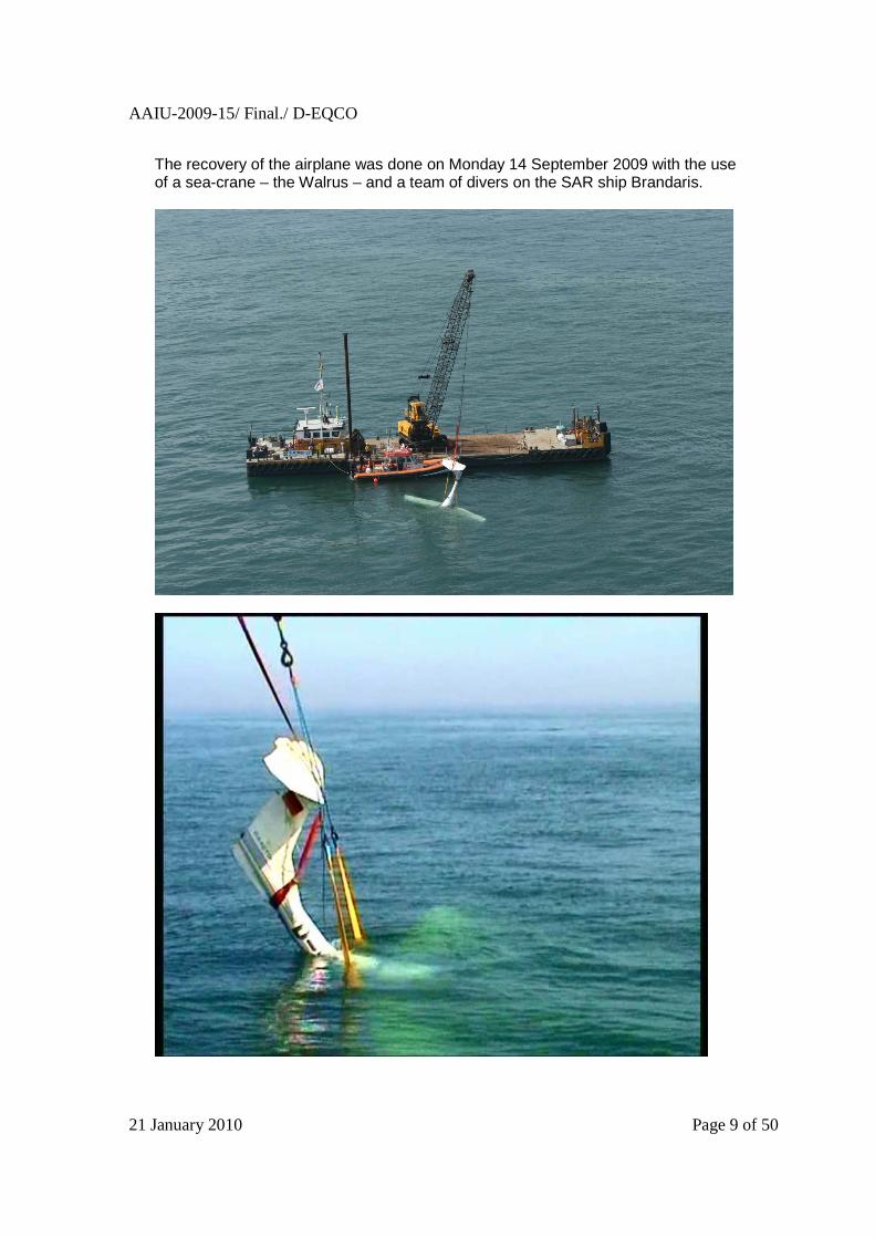
The recovery of the airplane was done on Monday 14 September 2009 with the use of a sea-crane – the Walrus – and a team of divers on the SAR ship Brandaris.

AAIU-2009-15/ Final./ D-EQCO
21 January 2010 Page 10 of 50
All 3 blades of the propeller were broken, indicating a rotation while hitting the sea surface.
1.4. Other damage
The recovery was decided also in order to avoid pollution of the sea bed.
1.5. Personnel information
Pilot . Sex: Male Age: 44 Nationality: Dutch Licence: Private Pilot Licence – issued by the Belgian CAA on 25 June
2008, transferred from a German LBA licence first issued on 24 June 2002. The licence is valid until 25 June 2013.
Ratings: SEP (land) - valid until 31 May 2011. Medical: Class 2 issued on 11 April 2008, valid until 24 April 2010. The pilot stated he had a total flight experience of ca 735 FH (in June 2008), of which the majority (600 FH) were flown on this aircraft. The last flight check was performed on 12 May 2009 for the revalidation of the class rating.

AAIU-2009-15/ Final./ D-EQCO
21 January 2010 Page 11 of 50
1.6. Aircraft information
1.6.1. General
The Diamond DA-40 D is a single engine light aircraft designed by Diamond Aircraft Industries. DA-40 Ds are produced at Diamond's aircraft factories in Wiener Neustadt, Austria. The DA-40 D is a four-seat low-wing cantilever monoplane made from composite materials. It has a fixed nose-wheel landing gear and a T-tail. The DA-40 D uses a Thielert "Centurion" 135 hp (99 kW) diesel engine and burns diesel or jet fuel. It has a variable pitch propeller and FADEC (single lever) engine control. The first flight of the DA-40 D was made on Nov. 28, 2002. The Type Certificate is EASA.A.022.

AAIU-2009-15/ Final./ D-EQCO
21 January 2010 Page 12 of 50
Characteristics
Weight Maximum take-off weight (Normal): 1150 kg Empty weight: 814 kg Speeds Normal operating range of speed: 52 KIAS – 129 KIAS. Operating range with flaps fully extended: 49 – 91 KIAS Manoeuvering speed (VA): 108 KIAS. Max. structural cruising speed (VNO): 129 KIAS Max Never Exceed Speed (VNE): 178 KIAS Stall speed (1150 kg - 0° bank - flaps up): 52 KIAS Gliding ratio With a windmilling propeller, the glide ratio is 8.8; i.e. for every 1000 ft of altitude loss the maximum horizontal distance travelled in still air is 1.45 NM. With a blocked propeller, the glide ratio is 10.3; i.e. for every 1000 ft of altitude loss the maximum horizontal distance travelled in still air is 1.70 NM. Gliding speed is 73 KIAS (1150 kg) – 68 KIAS (1000 kg).
Airframe Manufacturer:.Diamond Aircraft Industries Type: DA-40 D Serial Number: D4.094 Built year: 2004 Registration: D-EQCO Certificate of Registration: L 29274 issued by the Luftfahrt-Bundesamt
on 14 May 2004
Certificate of Airworthiness: L 29274 issued by the Luftfahrt-Bundesamt on 14 May 2004. Last annual inspection performed by EASA DE.145.0113 on 26 September 2008, valid until September 2009.
Total Flight Hours: 833.5 FH
Engine Manufacturer: Thielert Aircraft Engines GmbH Type: TAE 125-01 Serial: 02-01-0406-SL01-104-0053 Total Flight Hours: 815.3 FH

AAIU-2009-15/ Final./ D-EQCO
21 January 2010 Page 13 of 50
Propeller Manufacturer: MT-propeller Type: MTV-6-A/187-129 Serial: 04004 Total Flight Hours: 833.5 FH
Operation. The airplane was operated on an average of 250 FH per year, until end October 2008. In May 2008, the airplane was rented to Westflug Aachen. After 25 October 2008, it flew back to EBKT; the airplane had accumulated 829:23 FH at that time. It was put on sale shortly thereafter.
The airplane was put in a hangar until the 18 April 2009. At that date, it was put outside on the grass apron.
The airplane last flights were performed:
- on 7 December 2008, from EBKT to EBUL and back - on 11 January 2009, from EBKT to EBFN and back.
Maintenance The routine maintenance program features checks every 100, 200 and 1000 hours, as well as an annual check and a 2000 hours structural check. The situation of D-EQCO was as follows:
Inspection Last performed Next to be
performed at Remaining
100 hours 02 July 2008 855:38 FH 22 FH 200 hours 02 July 2008 955:38 FH 122 FH 1000 hours 1000 FH 167 FH 2000 hours 2000 FH 1167 FH Annual Check 26 September 2008 26 September 2009 1 month

AAIU-2009-15/ Final./ D-EQCO
21 January 2010 Page 14 of 50
There are also a series of components to be replaced after a fixed time, among others:
Component Time limit Remaining Engine 1000 FH 171 FH Clutch 300 FH 23 FH Gearbox 300 FH 23 FH High Pressure Pump 300 FH 23 FH Alternator excitation battery 1 year 1 month Rudder cables (*) 3000 FH / 5 years wof Due. Fuel Hoses (*) 5 years Due. Coolant hoses (*) 5 years Due. Oil hoses (*) 5 years Due Fuel tank vent hoses 5 years Due Interconnecting fuel hoses 5 years Due Propeller 72 Months / 2000 FH 6 Months
(*) Airworthiness Limitation – Replacement requirements
The maintenance was performed by a Part-145 Approved Maintenance Organisation: LBA.0113 - Westflug Aachen, Germany. The last maintenance on the airplane was performed on 20 October 2008, the pilot had reported that the engine was starting with difficulties. The Glow Plugs were identified as the defect causing the problem, and subsequently replaced by factory-new items. The engine was successfully tested. As indicated in the table here above, 6 hard time items became due in February 2009. 4 of these items are part of the Airworthiness Limitation Requirements (Replacement requirements; Airplane Maintenance Manual - Doc 06-02.01 Chapter 04-00-00 p4). These items were overdue on 22 August 2009. The Diamond AMM refers to the Thielert 125-01 Operation and Maintenance Manual for the items specific to the engine. This manual requires (Ch. 02-OM-06-01 dtd 05.04.2005) that in order to protect the engine against corrosion, the engine must be started-up for at least 20 minutes each month. This was not performed after January 2009.
The airplane was reaching a critical operating time, needing the replacement of some important component (engine, clutch).
Owner Q Company.

AAIU-2009-15/ Final./ D-EQCO
21 January 2010 Page 15 of 50
1.6.2. The propulsion system
The Diamond DA-40 D is equipped with a Thielert TAE 125-01, CENTURION 1,7 engine. It is a 1.7 liter (103 cu in) turbo charged, 4 cylinder, 4 valve DOHC common rail diesel engine with FADEC (full authority digital engine control). The engine produces 135 Hp (99 kW). The engine drives a variable pitch propeller through a reduction gearbox and an overload clutch.

AAIU-2009-15/ Final./ D-EQCO
21 January 2010 Page 16 of 50
FADEC System. The system allows the pilot to control all engine parameters through a single lever. The pilot simply selects the power level with the load lever, and, according to environmental conditions, the FADEC regulates all engine parameters accordingly.
There are five main control loops:
1. Boost Control 2. Fuel Injection Control 3. Rail Pressure Control 4. Propeller Control 5. Glow Plug Control.

AAIU-2009-15/ Final./ D-EQCO
21 January 2010 Page 17 of 50
Propeller Control The propeller pitch control system is integrated into the engine. The pitch is controlled by the FADEC and a CSU (Constant Speed Unit). Depending on the power setting – the position of the power lever (Load %) -, the propeller pitch and engine RPM are adjusted. The pitch control system is such that, without input signal or without hydraulic pressure from the CSU, the propeller blades are kept towards fine pitch through a pre-loaded spring (return spring) and the centrifugal twisting moments. The input signal generates a hydraulic pressure to activate an internal piston moving the blades towards coarse pitch. If the hydraulic pressure from the CSU fails, the blades turn towards fine pitch. If the CSU fails during flight and power setting remains unchanged, the propeller (engine) will go to over-speed. Gearbox and clutch The engine is equipped with a Gearbox to reduce RPM from the 3900 /min maximum of the engine to 2300 RPM at the propeller. The reduction ratio of the gearbox is 1.69:1. A clutch is installed between the engine and the gearbox. The purpose of the clutch is to decouple the engine vibrations from the propeller during normal operation and to limit the load to the crankshaft during startup and shutdown by decoupling the rotating mass of the propeller. The clutch is not operated by the pilot. The gearbox and clutch are life-limited to 300 Flight hours. If the clutch would fail, during flight and power setting remains unchanged, the engine will go to over-speed.
Gearbox Clutch

AAIU-2009-15/ Final./ D-EQCO
21 January 2010 Page 18 of 50
Engine Control For Diesel engines the engine power is proportional to the manifold air pressure, the rpm and the fuel flow. The indicated power in % is calculated by the FADEC based on the values measured by the engine sensors. a. Fuel Flow.
The fuel is injected in the cylinders through a common rail system. The working principle of the common rail injection is a high pressure reservoir of fuel (rail) which feeds the injectors. The maximum pressure in the reservoir is about 1350 bar, and is controlled through a valve. Because fuel is available at any desired pressure, the injection duration can also be controlled for a given injected volume. Fuel enters the common rail directly from the high-pressure pump. The actual fuel pressure in the rail (and therefore to the injectors) is measured by the rail pressure sensor. The FADEC interprets the rail pressure, compares it to a target value, and adjust the rail pressure control valve to reach the correct pressure. Fuel is supplied to the injectors through the injector supply ports.
b. RPM.
The propulsion power is determined by the FADEC according to the curve hereunder. The FADEC controls a CSU (Constant Speed Unit) acting on the propeller pitch angle. The CSU regulates the engine speed by varying the propeller pitch in function of the selected load in the cockpit (position of the Power Lever )
PropellerRPM
1400
1600
1800
2000
2200
2400
20 30 40 50 60 70 80 90 100
Load (%)
RP
M
PropellerRPM
Load / Propeller RPM
At lower power settings (below 20%), the propulsion system puts the blades towards the low pitch, and the system works more or less as a fixed pitch propeller; the flight data (altitude, speed) would influence the propeller RPM. At idle, the propeller RPM would be around 890 RPM; the engine RPM around 1500 RPM.

AAIU-2009-15/ Final./ D-EQCO
21 January 2010 Page 19 of 50
c. Manifold Air Pressure (MAP)
The manifold absolute pressure measurement is used to measure the amount of air flowing into the engine. The mass of air is proportional to the air density, which is proportional to the absolute pressure and inversely proportional to the absolute temperature.
1.6.3. Airplane Flight Manual
The airplane flight manual defines the actions necessary in case of abnormal situations: In particular para 3.2.3. deals with Engine Problems in Flight.
(a) engine running roughly.
• Airspeed 73 KIAS (1150 kg) • Power Lever: MAX • … • ECU SWAP:
Para 3.2.6. deals with Defective RPM regulating system
(a) Oscillating RPM
• Power setting: change (if the problem does not clear)
• ECU SWAP
(b) Propeller overspeed Constant propeller overspeed indicates that the defective governor holds the propeller blades at the fine pitch stop.
• Power lever: as required to maintain 2300 RPM • ECU SWAP
Flight to the nearest airfield can be continued with a lower power setting and at a lower airspeed. Climb and go-around remain possible.

AAIU-2009-15/ Final./ D-EQCO
21 January 2010 Page 20 of 50
(c) Propeller underspeed
The propeller speed is constantly below the speed that is correct for the given power setting. This indicates that the governor holds the propeller blades at the high pitch stop.
• Power lever: as required • ECU SWAP
Due to this problem, the propeller RPM will drop to 1400 RPM or below. There will be no climb performance and no go-around power available. Level flight should be possible except in rough weather.
1.7. Meteorological information
Conditions at the Oostdijkplatform. Wind: Direction: 250° Speed: 8 knots Visibility: more than 10 miles Clouds: few at 2700 ft Pressure: 1025 mb Temperature: 20°C Sea condition: Seawater temperature: 18.9°C Wave height: 50 cm
1.8. Aids to Navigation
The airplane was equipped for IFR flights with 2 Garmin GNS 430 GPS and Garmin GTX 330 mode S transponder.

AAIU-2009-15/ Final./ D-EQCO
21 January 2010 Page 21 of 50
1.9. Communication
Radar Trace. The path of the airplane has been recorded by the Belgocontrol radar in Steenokkerzeel. This allowed to reconstruct the flight – see page 6. The data generated by radar used in Ostend for approach are not recorded. The radar gives the position, the track followed by the airplane, and the ground speed (in knots); the altitude data (in 100 ft) originates from the airplane’s equipment.
Radar Image showing D-EQCO (squawk 6351) at 1500 ft (descending from 2000 ft) – 91 knots ground speed at the moment the pilot is reporting engine problems and notifies his intention to retur n to the coast line
(10:40:37)
AAIU-2009-15/ Final./ D-EQCO
21 January 2010 Page 22 of 50
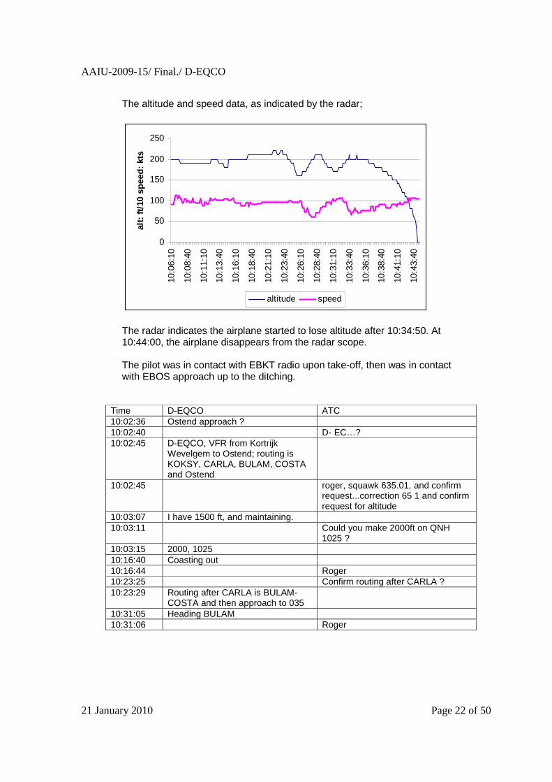
The altitude and speed data, as indicated by the radar;
0
50
100
150
200
250
10:0
6:10
10:0
8:40
10:1
1:10
10:1
3:40
10:1
6:10
10:1
8:40
10:2
1:10
10:2
3:40
10:2
6:10
10:2
8:40
10:3
1:10
10:3
3:40
10:3
6:10
10:3
8:40
10:4
1:10
10:4
3:40
alt:
ft/10
spe
ed: k
ts
altitude speed
The radar indicates the airplane started to lose altitude after 10:34:50. At 10:44:00, the airplane disappears from the radar scope. The pilot was in contact with EBKT radio upon take-off, then was in contact with EBOS approach up to the ditching.
Time D-EQCO ATC 10:02:36 Ostend approach ? 10:02:40 D- EC…? 10:02:45 D-EQCO, VFR from Kortrijk
Wevelgem to Ostend; routing is KOKSY, CARLA, BULAM, COSTA and Ostend
10:02:45 roger, squawk 635.01, and confirm request...correction 65 1 and confirm request for altitude
10:03:07 I have 1500 ft, and maintaining. 10:03:11 Could you make 2000ft on QNH
1025 ? 10:03:15 2000, 1025 10:16:40 Coasting out 10:16:44 Roger 10:23:25 Confirm routing after CARLA ? 10:23:29 Routing after CARLA is BULAM-
COSTA and then approach to 035
10:31:05 Heading BULAM 10:31:06 Roger

AAIU-2009-15/ Final./ D-EQCO
21 January 2010 Page 23 of 50
Time D-EQCO ATC 10:40:30 D-EQCO ? 10:40:35 Go Ahead Sir 10:40:37 Returning immediately to the coast
line due to funny noise in my engine
10:40:42 That is copied, Sir 10:40:47 You can proceed straight ahead to
ONO 10:40:50 I’ll try first to reach the coast line 10:40:57 The radar shows the airplane turning towards the coast line. 10:41:10 The shortest distance towards the
shore line is about 15 Nm on track 130
10:41:30 130 10:41:33 Please keep me informed on
intentions and if assistance is needed
10:41:40 I’m trying to maintain altitude, but this is difficult
10:43:21 For information, we have advised Sea King helicopter already and they are moving towards your position
10:43:22 Steering to a vessel for rescue 10:43:29 I won’t make it, there’s a vessel
here.
10:43:34 That is copied, Sir 10:44:39 D-EQCO disappears from the radar scope.
1.10. Airport information
Not Applicable.

AAIU-2009-15/ Final./ D-EQCO
21 January 2010 Page 24 of 50
1.11. Flight Recorders
The airplane is not equipped with a flight recorder, but the TAE-125 engine is equipped with a Digital Engine Control Unit (FADEC) that keeps some engine parameters in memory. D-EQCO was equipped with a FADEC p/n 02-7610-55001R1 (serial TAE125-ECU #1594 – Manufactured 08/2003). The FADEC consists of two separate, redundant ECUs. Both ECUs are operational at all times, but only one is active. The selection is either done automatically, depending on an internal health diagnostic system, or manually by the pilot through a switch in the cockpit.
Each ECU is storing the control parameters during engine operation (last 2:51 hours) in a digital memory. Also, all system failures (events) encountered are recorded for the entire FADEC life. The FADEC of D-EQCO was retrieved upon recovery of the airplane, and kept in demineralised water until the read-out, as per instructions of Thielert. The FADEC was dispatched for read-out to the facility of the BFU in Braunschweig, Germany on Thursday 17 September 2009. The read-out occurred on the next day. Both ECUs were in good condition, and after cleaning, drying and inspection, the ECU cards were wired for retrieval of the data.

AAIU-2009-15/ Final./ D-EQCO
21 January 2010 Page 25 of 50
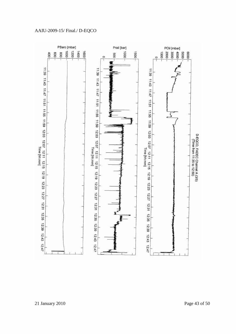
The data stored in both ECU could be retrieved, and the graphs of the last flight for both ECU are given in appendix. Failure reports
On the day of the last flight, the FADEC reported the following events:
- PRail Sensor failed for 10,0 seconds (4 times) - PRail Sensor failed for 32,3 seconds - High positive PRail delta: up to 917 bar for 10,0 seconds - PRail Sensor failed for 29,3 seconds - High positive PRail delta: up to 917 bar for 29,4 seconds.
AAIU-2009-15/ Final./ D-EQCO
21 January 2010 Page 26 of 50
These events were generated during the attempts of starting the engine on ground in EBKT, but were not repeated during the flight. A PRail Sensor failure entry in the eventlog would result in an illumination of the engine caution light. Before taking off, the pilot must verify that the caution light remains extinguished. (AFM Ch. 4A para 3.6). During the flight itself, no failure event were logged. Only after the ditching, the FADEC logs the following anomalies, which are due to the ditching itself.
- PRail Sensor failed for 6,6 seconds - TAir Sensor failed for 2,6 seconds - TAir Sensor failed for 2,1 seconds.
A preliminary analysis of the data was done on the spot by the specialist of the BFU-Germany, Thielert and AAIU (Belgium).
1.12. Wreckage and Impact information
The airplane was landed on the sea, tail first, and did not suffer dramatic damages in the process. It was nearly intact when it reached the sandy bottom of the sea, besides the loss of the rudder, the engine cowls, and the propeller. The airplane suffered more damages when the water stream lifted the airplane off the bottom, and brought it on its back.
1.13. Medical and Pathological information
Not Applicable
1.14. Fire
There was no fire
1.15. Survival Aspects
The pilot performed a perfect sea landing, and wore a survival jacket when exiting the plane.
1.16. Test and Research
Not applicable.
AAIU-2009-15/ Final./ D-EQCO
21 January 2010 Page 27 of 50
2. Analysis. 2.1. The problem .
The pilot stated that the engine started to make a strange noise, accompanied by heavy vibration, and that, although the engine was still running, the propeller did not provide thrust. The pilot stated he was unable to maintain altitude. To illustrate the event, the pilot stated that the problem could have been caused by a bird strike that would have damaged the propeller, from which the initial blow would have been unnoticed.
2.2. FADEC data.
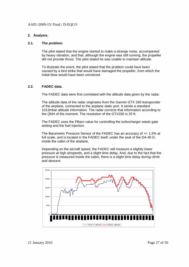
The FADEC data were first correlated with the altitude data given by the radar. The altitude data of the radar originates from the Garmin GTX 330 transponder of the airplane, connected to the airplane static port. It sends a standard 1013mbar altitude information. The radar corrects that information according to the QNH of the moment. The resolution of the GTX330 is 25 ft. The FADEC uses the PBaro value for controlling the turbocharger waste gate setting and the fuel injection. The Barometric Pressure Sensor of the FADEC has an accuracy of +/- 1.5% at full scale, and is located in the FADEC itself; under the seat of the DA-40 D, inside the cabin of the airplane. Depending on the aircraft speed, the FADEC will measure a slightly lower pressure at high airspeeds, and a slight time delay. And, due to the fact that the pressure is measured inside the cabin, there is a slight time delay during climb and descent.
0
500
1000
1500
2000
2500
ECU-A altitude Radar altitude

AAIU-2009-15/ Final./ D-EQCO
21 January 2010 Page 28 of 50
The Barometric Pressure Sensor of the FADEC altitude data quite equivalent to the reading on the radar scope.
2.3. Analysis.
Considering the definition of the problem, we will consider the flight in 3 different periods:
altitude
0
500
1000
1500
2000
2500
Tim
eInd
ex
9:53
:30
9:55
:51
9:58
:12
10:0
0:33
10:0
2:54
10:0
5:15
10:0
7:36
10:0
9:57
10:1
2:18
10:1
4:39
10:1
7:00
10:1
9:21
10:2
1:42
10:2
4:03
10:2
6:24
10:2
8:45
10:3
1:06
10:3
3:27
10:3
5:48
10:3
8:09
10:4
0:30
10:4
2:51
altitude
Period 1: Normal flight –the airplane is taking off , climbing and descending,
showing the engine is delivering thrust. These data, the data of the previous flights, along with data from the engine manufacturer were used as reference.
Period 2: The airplane descends continuously.
From 10:34:55 to 10:44:34
Period 3: Ditching. From 10:44:35 to 10:45:27.
Period 1: Normal Flight Period 2
Period 3

AAIU-2009-15/ Final./ D-EQCO
21 January 2010 Page 29 of 50
Engine Parameters; The following engine parameters during Period 2 were analyzed, in order to determine the performance of the whole propulsion system. - Load. - Engine RPM. - MAP - Common Rail Pressure.
A normal working of the engine should be reflected by a determined RPM in function of the Load, i.e. the position of the Power Lever. The working of the propeller should be reflected by the power delivered by the engine; assessed by the MAP and Common Rail Pressure. A normal working of the propeller should reflect in a constant power in function of the Load. A loss of propulsion (as in the case the pitch control would fail and put the propeller in low pitch) would result in a lower power associated with a normal engine RPM. An erratic propulsion (as in the case the clutch would glitch) would be reflected by an erratic working of the engine; short cycles of engine overspeed followed a reduction of RPM. In all cases, a loss of propeller efficiency as indicated by the pilot, either through internal failure or external action (propeller blade damaged by bird strike) will be reflected by fluctuations in engine power, and in most cases such event will cause a reduction of engine power.
The procedures defined by the manufacturer to cope with these failures are discussed under para 2.4. hereunder. The evolution of the engine parameters during the impact phase (period 3) is analysed under para 2.7. hereunder.

AAIU-2009-15/ Final./ D-EQCO
21 January 2010 Page 30 of 50
Load % The Load is the actual position of the Engine control handle, as positioned by the pilot. It gives the pilot’s demand in percentage of the total power. Between 10:34:50 and 10:44:29, the power lever was kept below the normal position for cruise; the Load was set at 44.72 %
Load %
0
5
10
15
20
25
30
35
40
45
50
10:3
4:50
10:3
5:16
10:3
5:42
10:3
6:08
10:3
6:34
10:3
7:00
10:3
7:26
10:3
7:52
10:3
8:18
10:3
8:44
10:3
9:10
10:3
9:36
10:4
0:02
10:4
0:28
10:4
0:54
10:4
1:20
10:4
1:46
10:4
2:12
10:4
2:38
10:4
3:04
10:4
3:30
10:4
3:56
10:4
4:22
UTC Time (hh:mm:ss)
Load
%
Load %
During the whole 10 minutes that lasted Period 2, there is no change in the position of the Power Lever recorded. The power setting of 44.72% is lower than the normal setting for cruise, as indicated in the airplane flight manual

AAIU-2009-15/ Final./ D-EQCO
21 January 2010 Page 31 of 50
Engine RPM. The engine responded to the demand, and turned at a constant value around an average of 3128 rpm. This value is corresponding to the calculated value.
0
500
1000
1500
2000
2500
3000
3500
10:3
4:50
10:3
5:16
10:3
5:42
10:3
6:08
10:3
6:34
10:3
7:00
10:3
7:26
10:3
7:52
10:3
8:18
10:3
8:44
10:3
9:10
10:3
9:36
10:4
0:02
10:4
0:28
10:4
0:54
10:4
1:20
10:4
1:46
10:4
2:12
10:4
2:38
10:4
3:04
10:4
3:30
10:4
3:56
10:4
4:22
UTC Time (hh:mm:ss)
RP
M
Engine RPM
The engine RPM does not show erratic operation, such as would be expected in the case of a glitch of the clutch. MAP The manifold absolute pressure measurement shows a relatively constant value, increasing slightly as the altitude goes down. Typical value for the MAP are: - Take-off: 2300 mbar. - Cruise 63 %: 1700 mbar - Idle: 1080 mbar The value of 1400 mbar recorded is normal for a load of 44 %, as set by the position of the power lever.
MAP (mbar)
0
200
400
600
800
1000
1200
1400
1600
10:3
4:50
10:3
5:16
10:3
5:42
10:3
6:08
10:3
6:34
10:3
7:00
10:3
7:26
10:3
7:52
10:3
8:18
10:3
8:44
10:3
9:10
10:3
9:36
10:4
0:02
10:4
0:28
10:4
0:54
10:4
1:20
10:4
1:46
10:4
2:12
10:4
2:38
10:4
3:04
10:4
3:30
10:4
3:56
10:4
4:22
MAP (mbar)

AAIU-2009-15/ Final./ D-EQCO
21 January 2010 Page 32 of 50
Common Rail Pressure
Pressure Common rail
0100200300400500600700800900
10:3
4:50
10:3
5:16
10:3
5:42
10:3
6:08
10:3
6:34
10:3
7:00
10:3
7:26
10:3
7:52
10:3
8:18
10:3
8:44
10:3
9:10
10:3
9:36
10:4
0:02
10:4
0:28
10:4
0:54
10:4
1:20
10:4
1:46
10:4
2:12
10:4
2:38
10:4
3:04
10:4
3:30
10:4
3:56
10:4
4:22
bar
Pressure Common rail
Adjustment Pressure Common Rail
0100200300400500600700800900
10:3
4:50
10:3
5:16
10:3
5:42
10:3
6:08
10:3
6:34
10:3
7:00
10:3
7:26
10:3
7:52
10:3
8:18
10:3
8:44
10:3
9:10
10:3
9:36
10:4
0:02
10:4
0:28
10:4
0:54
10:4
1:20
10:4
1:46
10:4
2:12
10:4
2:38
10:4
3:04
10:4
3:30
10:4
3:56
10:4
4:22
bar
Adjustment Pressure Common Rail
The common rail pressure is fairly constant around 650 bar. Typical values are: - Take-off: 1350 bar - Cruise 64%: 1000 bar - Idle: 350 bar The value of 650 bar, for both the pressure and adjustment parameters are reflecting a engine power consistent with the position of the power lever.

AAIU-2009-15/ Final./ D-EQCO
21 January 2010 Page 33 of 50
2.4. Flight Procedure.
We saw earlier in para. 1.6.3. that the procedure to apply by the pilot in case of engine/propulsion problems involves;
- modifying the power setting, and - swapping ECUs (switch in the cockpit).
The read-out of FADEC parameters shows that during the airplane descend, for the whole Period 2, the Engine control handle was kept in the same position. Also, the ECA in operation was ECU-A, from the take-off to the ditching. There are no ECU change recorded.
2.5. Engine inspection. The engine was inspected, and at the time of the recovery, the propeller rotated freely, driving the engine and its accessories. The electrical connections on the engine were intact. The drainage of oil in both the engine and gearbox did not reveal any catastrophic failure or abnormal condition.

AAIU-2009-15/ Final./ D-EQCO
21 January 2010 Page 34 of 50
2.6. Power Lever inspection.
The power lever is sending a position signal to the 2 internal units (ECUs) of the FADEC through 2 separate potentiometers. Both potentiometers (SP2841) were still connected to the power lever and despite the long exposure to salt water, were still operating within their specifications.
2.7. Impact (period 3).
Looking at Period 3; the Pbaro gives the following altitude evolution:
altitude
0
2000
4000
6000
8000
10000
12000
14000
10:4
4:35
10:4
4:38
10:4
4:41
10:4
4:44
10:4
4:47
10:4
4:50
10:4
4:53
10:4
4:56
10:4
4:59
10:4
5:02
10:4
5:05
10:4
5:08
10:4
5:11
10:4
5:14
10:4
5:17
10:4
5:20
10:4
5:23
10:4
5:26
time
feet altitude

AAIU-2009-15/ Final./ D-EQCO
21 January 2010 Page 35 of 50
We see a normal evolution from 10:44:35 until 10:45:11, where the sudden change indicates a first impact with the water surface. The position of the power lever for the same period shows the lever being retarded from 44% to 0% (idle) before impact, and some forward and back and forth movement after the first impact; the end position is fully forward (full power), probably due to the pilot holding the stick with the left hand, having his right hand on the power lever and be subjected to the deceleration as the airplane hit the water, Let us also note the pilot stated he “shut down the engine and restarted, without problem” in an attempt to identify the problem, but in this case this movement occurs quite late in the flight:
power lever position (Load %)
0
10
20
30
40
50
60
70
80
90
100
10:44
:35
10:44
:38
10:44
:41
10:44
:44
10:44
:47
10:44
:50
10:44
:53
10:44
:56
10:44
:59
10:45
:02
10:45
:05
10:45
:08
10:45
:11
10:45
:14
10:45
:17
10:45
:20
10:45
:23
10:45
:26
power lever position (Load %)
The engine RPM shows the following evolution:
engine RPM
0
500
1000
1500
2000
2500
3000
3500
10:44
:35
10:44
:38
10:44
:41
10:44
:44
10:44
:47
10:44
:50
10:44
:53
10:44
:56
10:44
:59
10:45
:02
10:45
:05
10:45
:08
10:45
:11
10:45
:14
10:45
:17
10:45
:20
10:45
:23
10:45
:26
engine RPM

AAIU-2009-15/ Final./ D-EQCO
21 January 2010 Page 36 of 50
The graph shows the engine RPM decreasing as a result of the command – the position of the power lever in idle – and besides two aberrations at 10:45:11 and 10:45:18 (corresponding with the 2 peaks of P Baro, see above), the engine RPM increases after 10:45:17. before dropping very rapidly to zero from 10:45:23 until the end. The MAP shows the same evolution.
MAP
0
200
400
600
800
1000
1200
1400
1600
10:44
:35
10:44
:38
10:44
:41
10:44
:44
10:44
:47
10:44
:50
10:44
:53
10:44
:56
10:44
:59
10:45
:02
10:45
:05
10:45
:08
10:45
:11
10:45
:14
10:45
:17
10:45
:20
10:45
:23
10:45
:26
mba
r
MAP
The engine parameter are showing that before impact, the power lever was retarded to idle for 37 seconds. After a first impact, the power lever was moving forward and the engine responded accordingly. The engine regained some power before shutting down.
2.8. Miscellaneous.
The findings made on the maintenance follow-up of the airplane (see Chapter 1.6. para “Maintenance) might have influenced the owner to put the airplane on sale, but had no influence on the accident itself. The meteorological conditions have had no impact on the accident, except that the conditions were ideal for a sea landing.
AAIU-2009-15/ Final./ D-EQCO
21 January 2010 Page 37 of 50
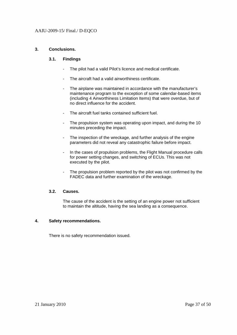
3. Conclusions.
3.1. Findings - The pilot had a valid Pilot’s licence and medical certificate. - The aircraft had a valid airworthiness certificate.
- The airplane was maintained in accordance with the manufacturer’s
maintenance program to the exception of some calendar-based items (including 4 Airworthiness Limitation Items) that were overdue, but of no direct influence for the accident.
- The aircraft fuel tanks contained sufficient fuel. - The propulsion system was operating upon impact, and during the 10
minutes preceding the impact.
- The inspection of the wreckage, and further analysis of the engine parameters did not reveal any catastrophic failure before impact.
- In the cases of propulsion problems, the Flight Manual procedure calls for power setting changes, and switching of ECUs. This was not executed by the pilot.
- The propulsion problem reported by the pilot was not confirmed by the FADEC data and further examination of the wreckage.
3.2. Causes. The cause of the accident is the setting of an engine power not sufficient to maintain the altitude, having the sea landing as a consequence.
4. Safety recommendations.
There is no safety recommendation issued.

AAIU-2009-15/ Final./ D-EQCO
21 January 2010 Page 38 of 50
THIS PAGE INTENTIONNALLY LEFT BLANK

AAIU-2009-15/ Final./ D-EQCO
21 January 2010 Page 39 of 50
APPENDIX: FADEC DATA
AAIU-2009-15/ Final./ D-EQCO
21 January 2010 Page 40 of 50
THIS PAGE INTENTIONNALLY LEFT BLANK

AAIU-2009-15/ Final./ D-EQCO
21 January 2010 Page 41 of 50

AAIU-2009-15/ Final./ D-EQCO
21 January 2010 Page 42 of 50
AAIU-2009-15/ Final./ D-EQCO
21 January 2010 Page 43 of 50

AAIU-2009-15/ Final./ D-EQCO
21 January 2010 Page 44 of 50

AAIU-2009-15/ Final./ D-EQCO
21 January 2010 Page 45 of 50

AAIU-2009-15/ Final./ D-EQCO
21 January 2010 Page 46 of 50

AAIU-2009-15/ Final./ D-EQCO
21 January 2010 Page 47 of 50

AAIU-2009-15/ Final./ D-EQCO
21 January 2010 Page 48 of 50

AAIU-2009-15/ Final./ D-EQCO
21 January 2010 Page 49 of 50

AAIU-2009-15/ Final./ D-EQCO
21 January 2010 Page 50 of 50