Embed Size (px)
Citation preview
CR 112068
- 3/
Final Report on Study of
Feedline Dynamic Effects onShuttle POGO Stability
5 My 7972
Contract NAS1:1"0836 SD72-SH-0039
FOR U.S. GOVERNMENT AGENCIES AND THEIR CONTRACTORS ONLY
Space DivisionNorth American Rockwell
https://ntrs.nasa.gov/search.jsp?R=19720024234 2020-07-18T22:01:29+00:00Z
CR 112068
Final Report on Study of
Feedline Dynamic Effects onShuttle POGO Stability
Prepared by O.D. DiMAGGloT. NISHIMOTO
R.H. LASSENStudy Manager
5 May 1972
Contract NAS1-10836 SD 72-SH-0039
Space DivisionNorth American Rockwell
Space DivisionNorth American Rockwell
FOREWORD .
This report is a description of work performed
under Contract NAS1-10836, Study of Feedline
Dynamic Effects on Shuttle POGO Stability, by the Space
Division (SD) of North American Rockwell Corporation
(NR) for the National Aeronautics and Space Administra-
tion, Langley Research Center, Hampton, Virginia,
during the period of 25 June 1971 to 2^ April 1972.
This work was conducted at NR/SD by 0. DiMaggio
and T. Nishimoto. Study Manager was R. H. Lassen of
NR/SD and the Technical Monitor was L. D. Pinson of
NASA Langley Research Center.
- 111 -SD 72-SH-0039
Space DivisionNorth American Rockwell
SUMMARY
The mathematical representation of a feedline is an important element in a
POGO analysis. The dynamic characteristics of a feedline have been determined
and the results presented in the form of transmission parameters. These
transmission parameters include the effects of wall deformation, distributed
damping, convective acceleration terms and the bulk modulus of the liquid.
In order to reduce the characteristic equation associated with the system
equations to a polynomial, it is necessary to approximate the transcendental
terms appearing in the transmission parameters by appropriate polynomial
expressions. The transmission parameters have been approximated using both
power and product series expansions. The feedline transfer functions of a
Shuttle Orbiter feedline configuration have been obtained using power and
product series approximations of 60th, 120th, 180th, and 2Uoth order. Bode
plots using the above polynomial approximations have been obtained and the
results compared with the "exact" solution. The "exact" solution to the
feedline transfer function have been obtained by using the transcendental terms
appearing in the transmission parameters.
The results show that the Shuttle Orbiter feedline may be modeled adequately
by using polynomial approximations for the transcendental functions appearing
-in—the—transmission—parameters-.—T-he—power—series—approach-has—been-shown—to
be preferable to the product series method.
- v -SD 72-SH-0039
Space DivisionNorth American Rockwell
CONTENTS
Section PaSe
I. INTRODUCTION - • • 1
II. SYSTEM EQUATIONS . . . • • . • • 3
n i . FEEDLINE DYNAMICS . . . . . . . 51 . Transmission Parameters . . . . . 62. Feedline Transfer Function for Straight
Feedline With Simple Compliance Pump . 183. Feedline Transfer Function of Straight
Feedline With Double Compliance Pump . 27
IV. , SHUTTLE OR BITER FEEDLINE . . . , . . 571. Modeling . . . • • • • • • 5?2. Numerical Results . . • .... • • 64
V. EIGENVALUES AND THE SOLUTION VECTOR . . 85
VI. CONCLUSIONS AND RECOMMENDATIONS . . 95'i
VII. ' REFERENCES . . • • • • • 97
APPENDICES . . • • • . . . • 99A. DETERMINATION OF TRANSMISSION
PARAMETERS . . . . . . . 9 9B . MERMORPHIC FUNCTIONS . . . . 1 0 5C. PRODUCT SERIES EXPANSION OF THE
FEEDLINE TRANSFER FUNCTION . . 107
D. LIST OF SYMBOLS U1
- vn -,SD 72-SH-0039
Space DivisionNorth American Rockwell
ILLUSTRATIONS
Figure Page
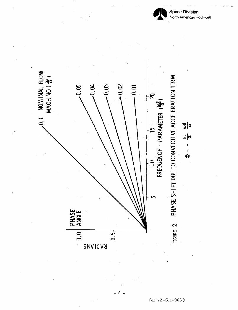
1 Engine Free-Body Diagram . . . . . . . . 42 Phase Shift Due to Convective Acceleration Term g
3-8 Power and Product Expansions - Hyperbolic Cosine(4th, 6th, 8th, 10th, 12th, and 14th Orders) . . . .12
9 Simplified Feedline . . . . . . . . . . i g10 Straight Line With Single Compliance Pump - "Exact" Solution • 2111 Straight Line With Single Compliance Pump - Damping
Lumped (One Segment) . . . . . . . .2212 Straight Line With Single Compliance Pump -
(Five Segments) . . . . . . . . . . 2 313 Peak Gain Vs. Number of Segments at w = 21.75 rad/sec . . 2414 Peak Gain Vs. Number of Segments at w = 215 rad/sec . • 2515 Peak Gain Vs . Nondimensional Frequency . . . . . 26
16-17 Straight Line With Double Compliance Pump- "Exact"Solution . . . . . . . . . . . -30
18-29 Straight Line With Double Compliance Pump - Power Series(4th, 8th, 12th, 16th, 20th, and 40th Order) . . . - 3 . 2
30-41 Straight Line With Double Compliance Pump - ProductSeries (4th, 8th, 12th, 16th, 20th, and 40th Order) ... 44
42 Shuttle Orbiter LOX Feedline 5843 Shuttle Orbiter LOX Feedline - Forward End . . . .5944 Shuttle Orbiter LOX Feedline - Aft End 6045 Feedline Geometry . . . . . . . . . • 61
46-47 Shuttle Orbiter Feedline - Exact Solution (Gain and Phase) . 6548-55 Shuttle Orbiter Feedliiie~ - Power Series (60thy -120th,--
180th, and 240th Order) 6756-63 Shuttle Orbiter Feedline - Product Series (60th, 120th,
180th, and 240th Order) 7564-65 Shuttle Orbiter Feedline - Product Series - 60th Order
(Gain a n d Phase) . . . . . . . . . . 9 366 Tubular Element . . . . . . . . . . • 99
—67--6S—Straight-Line-^Wlith-Single_C_ompliance Pump (Gain and Phase) . Qg
- ix -
SD 72-SH-0039
Space DivisionNorth American Rockwell
TABLES
Table Page
1 Damping Data 622 Feedline Data 633 Shuttle Orbiter Feedline Peak Gains . . . . . 834 Closed-Loop Roots • • 905 Undamped Natural Frequency a n d Damping . . . . 9 16 Solution Vector for First Root 92
- xi -
SD 72-SH-0039
Space DivisionNorth American Rockwell
I. INTRODUCTION
In order to perform a POGO stability analysis on the Shuttle Orbiter vehicle
an accurate model of the propellant feedline is required. The model of the
feedline must be made compatible with the stability program. The current
stability program at NR can handle up to UO fourth order differential equations
with constant coefficients. It determines the characteristic polynomials
associated with the stability equation and extracts the roots from these
polynomials. Experience has shown that the program gives good numerical
results for systems up to about 80th order. The transmission parameters for
an elemental section of a feedline have been obtained by solving the linearized
wave equation in the LaPlace domain. The transmission parameters include thel
effect of the convective acceleration terms and distributed damping. The
"exact" transmission parameters have been used for obtaining results in the
frequency domain and are useful in checking the numerical accuracy of the
polynomial approximations required for inclusion into the stability program.
Bode plots of the feedline transfer functions have been obtained for a
simplified feedline and a Shuttle Orbiter feedline configuration, using both
a power series and product series approximation to the transmission parameters.
The results have been compared with the "exact" solution.
The stability of the system and the solution vector were determined using
both the power and product series approximations for the transmission
parameters and the results compared.
- 1 -SD 72-SH-0039
Space DivisionNorth American Rockwell
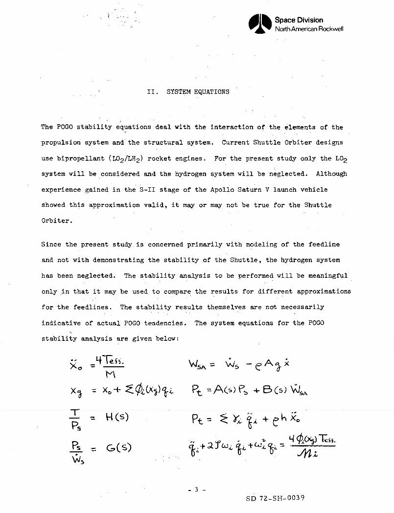
II . SYSTEM EQUATIONS
The POGO stability equations deal with the interaction of the elements of the
propulsion system and the structural system. Current Shuttle Orbiter designs
use bipropellant (l /LI ) rocket engines. For the present study only the LC>2
system will be considered and the hydrogen system will be neglected. Although
experience gained in the S-II stage of the Apollo Saturn V launch vehicle
showed this approximation valid, it may or may not be true for the Shuttle
Orbiter.
Since the present study. is concerned primarily with modeling of the feedline
and not with demonstrating the stability of the Shuttle, the hydrogen system
has been neglected. The stability analysis to be performed will be meaningful
only in that it may be used to compare the results for different approximations
for the feedlines. The stability results themselves are not necessarily
indicative of actual POGO tendencies. The system equations for the POGO,
stability analysis are given below:
X0H
Pt = A60 P* + BO)
- 3 -SD 72-SH-0039
Space DivisionNorth American Rockwell
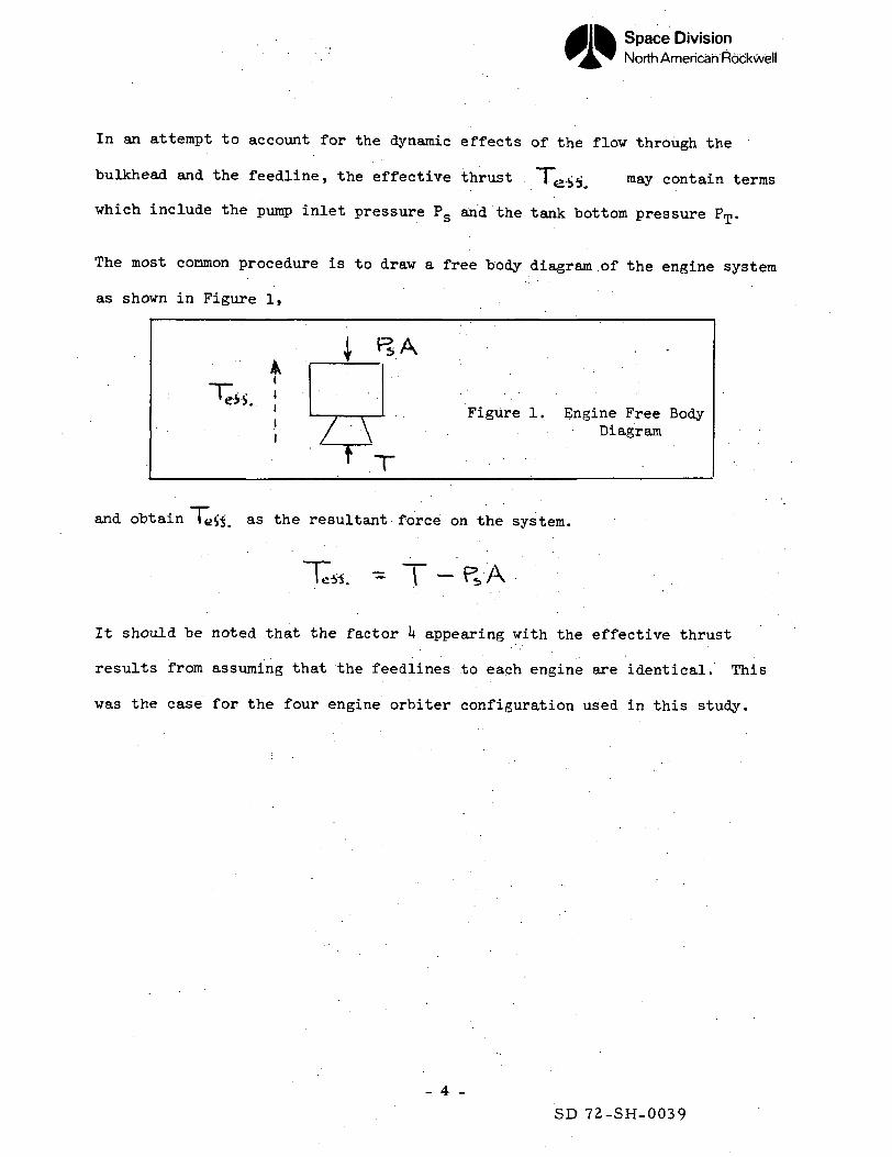
In an attempt to account for the dynamic effects of the flow through the
bulkhead and the feedline, the effective thrust ~Te. may contain terms
which include the pump inlet pressure PS and the tank bottom pressure PT.
The most common procedure is to draw a free body diagram of the engine system
as shown in Figure 1,
/A~~Figure 1. Engine Free Body
Diagram
and obtain l«ft. as the resultant force on the system.
T«. — T - PS, A
It should be noted that the factor k appearing with the effective thrust
results from assuming that the feedlines to each engine are identical. This
was the case for the four engine orbiter configuration used in this study.
- 4 -
SD 72-SH-0039
Space DivisionNorth American Rockwell
. . . III. FEEDLINE DYNAMICS • - '
Feedline Dynamics concerns itself with wave propagation in the propellant
lines and the dynamic characteristics of the pump. The approximate wave
equations for the lines are developed in Appendix A. The solutions of these
equations have been obtained and the results presented in the form of trans-
mission parameters. The effect of the convective acceleration terms and
distributed damping have been investigated using a simplified feedline and
the "exact" or transcendental form of the transmission parameters. The
transmission parameters have been approximated by polynomial expressions
using both the power series and product series approach. The feedline transfer
functions for a simplified feedline and a Shuttle Orbiter configuration have
been determined using these polynomial approximations and the results compared
with the "exact" solution.
- 5 -
SD 72-SH-0039
Space DivisionNorth Americarr'Rockwell
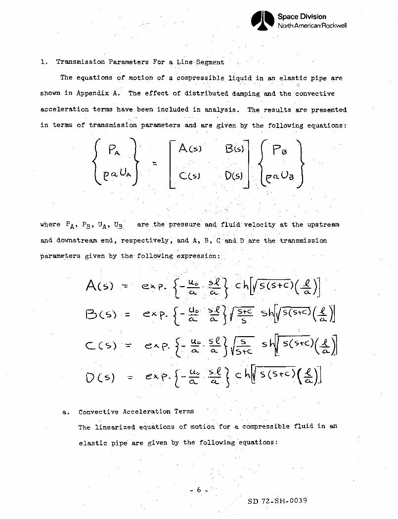
1. Transmission Parameters For a Line Segment
The equations of motion of a compressible liquid in an elastic pipe are
shown in Appendix A. The effect of distributed damping and the convective
acceleration terms have been included in analysis. .The results are presented
in terms of transmission parameters and are given by the following equations:
N
CO) DCs)
where P^, PB, U^, UB are the pressure and fluid velocity at the upstream
and downstream end, respectively, and A, B, C and.D are the transmission
parameters given by the following expression: - ' ' ••
CCs) =
DCs)
a. Convective Acceleration Terms •
The linearized equations of motion for a compressible fluid in an
elastic pipe are given by the following equations:
- 6 -
SD 72-SH-0039
Space DivisionNorth American Rockwell
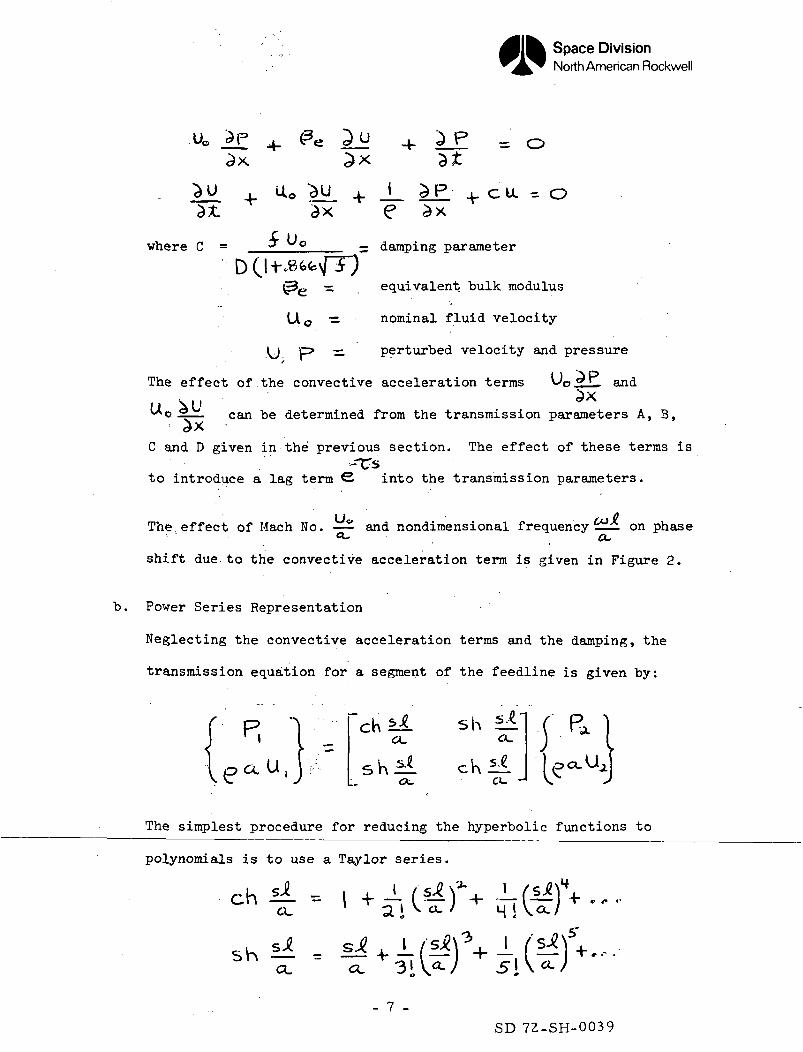
= 0
__ £P + C U = Oe ax
3"where C = 3" ° _ = damping parameter
( e — equivalent bulk modulus
LA0 •=. nominal fluid velocity
y p> — perturbed velocity and pressure
The effect of the convective acceleration terms oliJ-. and
^Xcan be determined from the transmission parameters A, B,
C and D given in the previous section. The effect of these terms is-TTs
to introduce a lag term S into the transmission parameters.
The effect of Mach No. — - and nondimensional frequency 1 on phaseCL. a.shift due to the convective acceleration term is given in Figure 2.
b. Power Series Representation
Neglecting the convective acceleration terms and the damping, the
transmission equation .for a segment of the feedline is given by:
**_ sha.
\ *i$ \ S @sh _ ch ±±.
The simplest procedure for reducing the hyperbolic functions to
polynomials is to use a Taylor series.
chil = | +-a. ' ai «• Ml
sh M - s* +^ CL - CL
- 7 -
SD 72-SH-0039
Space DivisionNorth American Rockwell
SNvmvy
UJ
I_UOO
Ouu
OO
O
tCO
UJto
11°
CD
0
II
e
- 8 -
SD 72-SH-0039
Space DivisionNorth American Rockwell
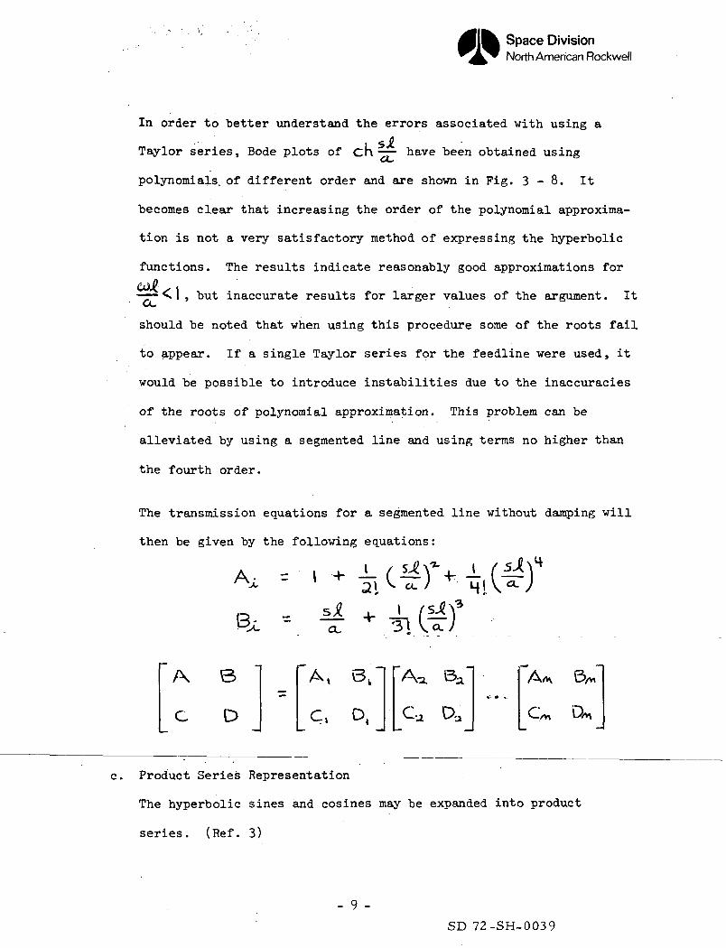
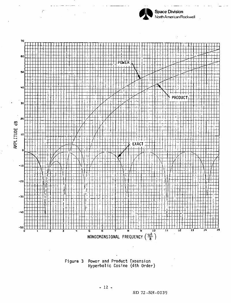
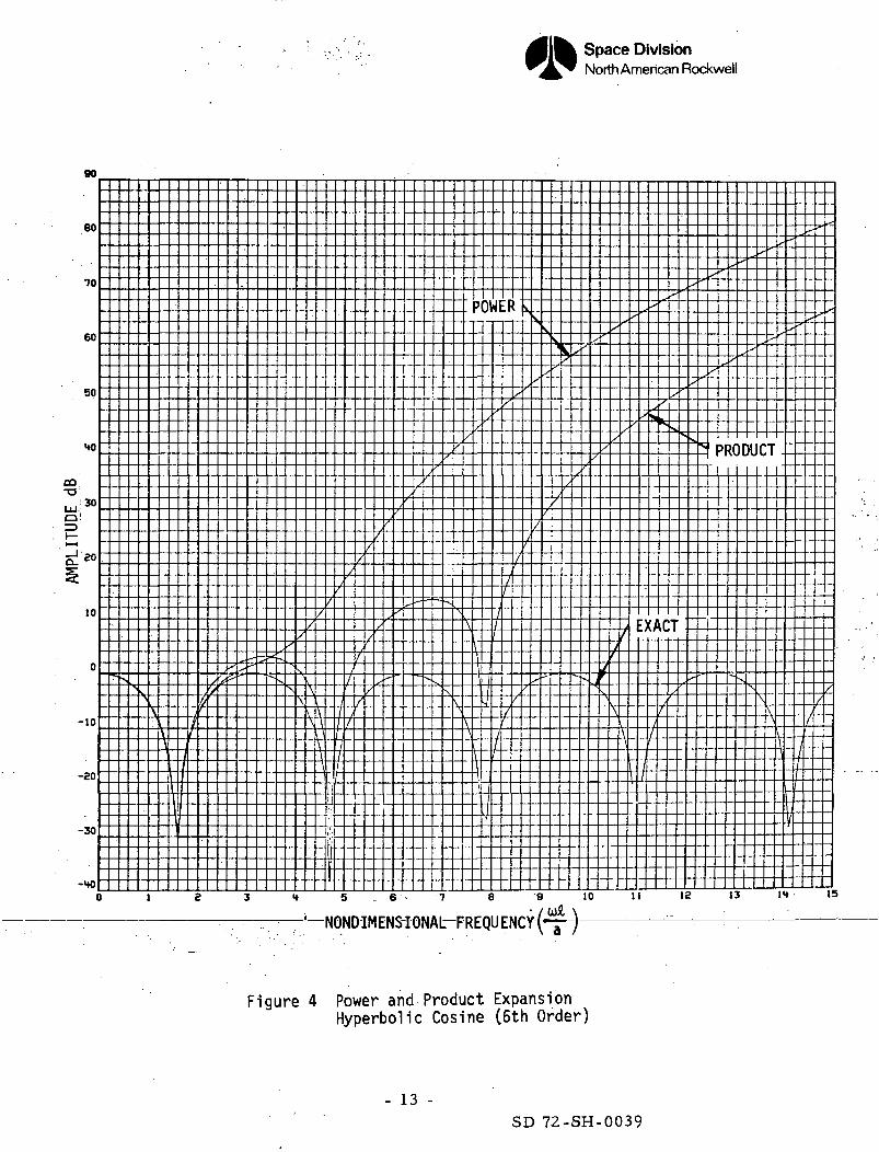
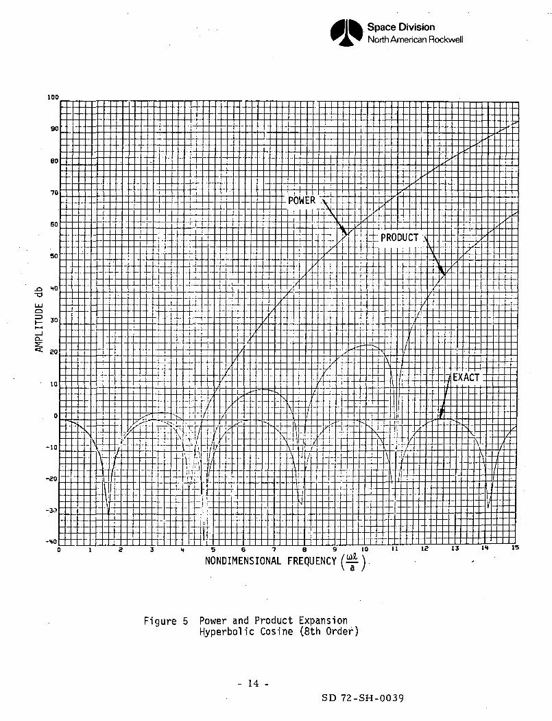
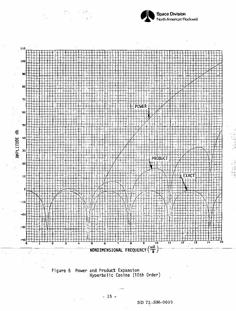
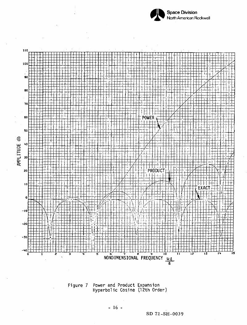
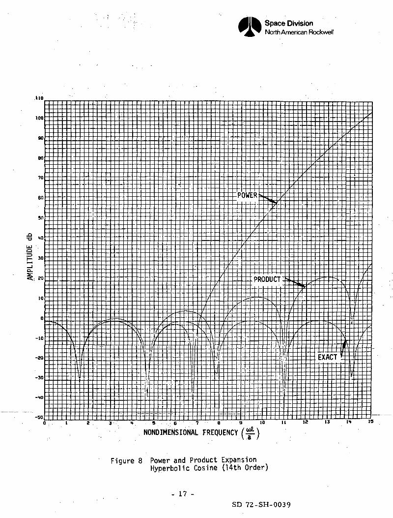
In order to better understand the errors associated with using a
Taylor series, Bode plots of cK — - have been obtained using
polynomials, of different order and are shown in Fig. 3-8. It
becomes clear that increasing the order of the polynomial approxima-
tion is not a very satisfactory method of expressing the hyperbolic
functions. The results indicate reasonably good approximations for• .
-— <. I , but inaccurate results for larger values of the argument. It
should be noted that when using this procedure some of the roots fail
to appear. If a single Taylor series for the feedline were used, it
would be possible to introduce instabilities due to the inaccuracies
of the roots of polynomial approximation. This problem can be
alleviated by using a segmented line and using terms no higher than
the fourth order.
The transmission equations for a segmented line without damping will
then be given by the following equations :
R - M 4- -L (Mf• • * ~ .<*-. /3i\o.;
A B
C D
A t 3k~
C, D,
FAa Ba-
_Cu D._
"A, 6,1
C^ D/v,
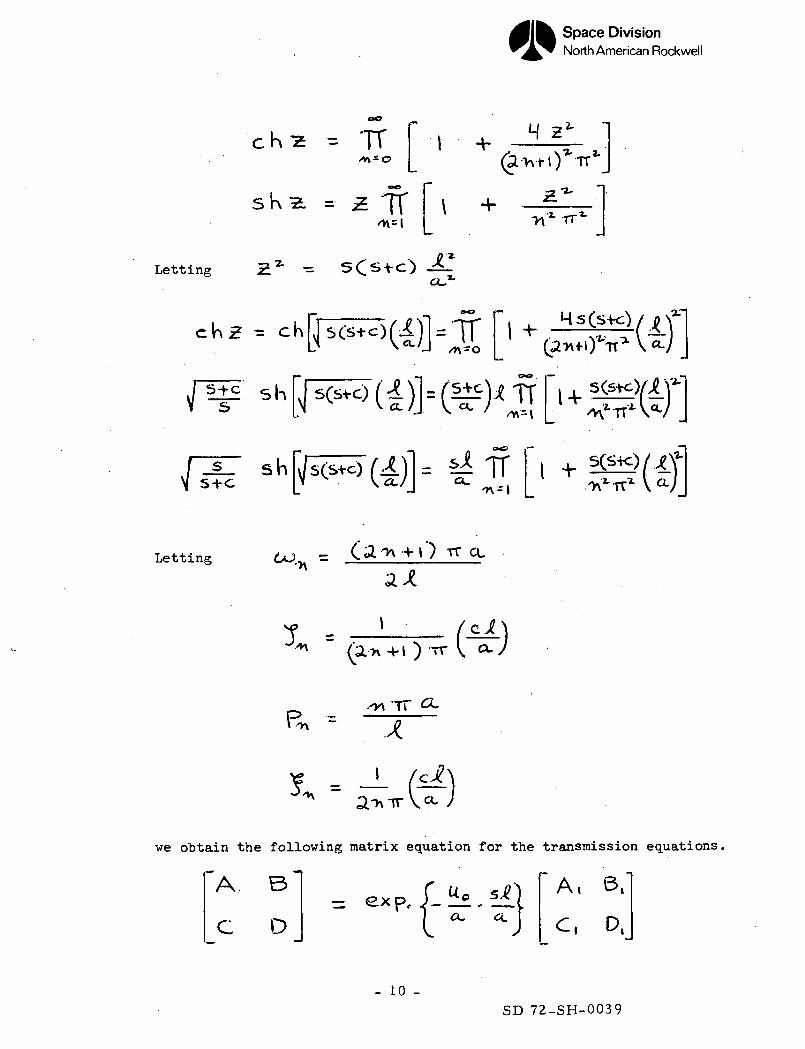
c. Product Series Representation
The hyperbolic sines and cosines may be expanded into product
series. (Ref. 3)
- 9 -
SD 72-SH-0039
Space DivisionNorth American Rockwell
Kz = TT i -t-
sK It
M 2*\1- t
^'Z'
Letting
s
Ss-t-c
^ cK
sh
sh
Letting 4- t') TT CL
(a.
we obtain the following matrix equation for the transmission equations.
A B
C D
A, 6k
C, P,
- 10 -SD 72-SH-0039
Space DivisionNorth American Rockwell
where
A, - TT
C, =
•>\-o
oO
ITw
It is clear from looking at the damping terms«
and 5,*, —
I (C.A" ~ ~
\)'
-"/ tha* the damPinS coefficient is inversely propor-
tional to the mode number.
One should, therefore, expect that the peaks which occur in the feed-
line transfer functions should be sharper at the higher frequencies.
This in fact, is what happens for this Shuttle Orbiter feedline
configuration (Figure U6) .
Bode plots of the hyperbolic cosine have been obtained using from 2
to 7 roots and are shown in Figures 3-8. The product expansions
by their very nature maintain the roots exactly, but the error in
gain increases with increasing frequency.
- 11 -SD 72-SH-0039
Space DivisionNorth American Rockwell
70
60
POWER
60
-U-
30
CO-aUJo
10
-ii
..LI- PRODUCT-.- -*—-*-{
EXACT
'/-10
-20
-30
-HO
-50
F
f
U-l-
Ti
ft::
—4
±r10 11 12 13 IH 15
NONDIMENSIONAL FREQUENCY
Figure 3 Power and Product ExpansionHyperbolic Cosine (4th Order)
- 12 -SD 72-SH-0039
Space DivisionNorth American Rockwell
90
eo
70
60
50
HO
CO-om'Q
10
-10
-80
-30
-to
v
\
sV
^1
11
t\I//
1]l
r~
/(
'.
s
^
^^^^
-^
k.
X
*
\
/
\
/
\
\
/
\\
\\\
/
11
//
1
1
/
r1
/
I
/
/
/
x
/
/
,
^
_,
^
s
-
„
-
1
/]
•-v
rf
s
• .
^
p
xX
\
\\
1 ) 1 e 3 4 5 . 6 7
)W!
/1
14
/1
S
:F
'
//
7
4
S
i
8
v
,
/
,
y
X
^
'
-
tf
/
L
^^
" >
x
7"
-
x
/
-
^x-
X !
X
^ EXAr
\
\ 'I
t 4-rL
9 10 11
xx^
X
xxr
X"
J.
^
ACT
-•,
.7
x "s^
^s
PRODU
" X
N
*•
£. '
^ '*"
^S^
^
'T- T
'v* Z
- 4 - - (- - f-
t
^
-"*
--
x/
--
12 13 14 15
-4—NONDIMENS-IONAL-FREQUENCY(-T-
Figure 4 Power and Product ExpansionHyperbolic Cosine (6th Order)
- 13 -SD 72-SH-0039
Space DivisionNorth American Rockwell
100
90
60
•70
60
POWER
i«
50
_QT3
HO
30
I I
7^
-H-
PRODUCT3J
-I
_ _ LI
MXT4X± t
•I-
10
LLi iTX
U
-10....
-so
-30
-HO
I±
•TT'/
M
_i-
a
V-i-^n
4__
EXACT
H 5 6 7 8 9
NONDIMENSIONAL FREQUENCY10 11 13 13 1H 15
(T)
Figure 5 Power and Product ExpansionHyperbolic Cosine (8th Order)
- 14 -SD 72-SH-0039
Space DivisionNorth American Rockwell
no
-Q1
•o
100
90
80
70
60
50
HO
30
20
10
0
-10
-20
-30
-HO()
sHX
-
V
_ _
4
.._
f
-
-
J
i
-
^
&
-
^
-_
—
-
*
--«
-•
• ,
-^-
i
b'\N
I
i
1_
[
?V-
f
7
L'
_
c
\
_L
--
Vt.^
5
1
-
/
f.
-
-
s\4\I
-
-
-
c
-
i
-
>
/
"-
-
//
-4
/
X
[/
N
i.
1
/
^
\
\
V
/
-
\\
/
_
ij
4
c
/
~ ./t
t
j
t
/.
j.
-
-
K
/
L-
)V
^
x/i
-
7
u!E
-/-
7
<-
-
J
R
/
-
/I
)
/
\ i\1,^-i
—
- - -
/
>RI
--
i
/
Dl
x
-
0
/
X\_
\
-
/
JC
b.
V
^_/
.__--
:i -
\-l--t
^i
i
--
.-
/,
i
:ri >
±
i
r/
!
)
/
/
/
--.
\
r
i
^*
/
L
-
3
X
—
tr*
*
•
A
x
^
C
/
1
i
-.
-
3
^
•S
"
x
_
•
J "
v
\-
-A
i
x
i
I/iy.
«
^
1£_
f
^f
I
fi1-
/j.i_^
^S~-
--
IE
"NONDIMENSIONAL
Figure 6 Power and Product ExpansionHyperbolic Cosine (10th Order)
- 15 -SD 72-SH-0039
Space DivisionNorth American Rockwell
no
100
90
so
70
60
50
_a-a
HO
i
T-
--J-POWER
IX
±
l__l^i_i^-4-4 - -
LJ-4--
±tw
30
so
10
-10
-so
-30
-40
il4-
/
±t±:#Ef\\F---^---f
•\r-r!
i f
H- =
02f
d±TXm:hPRODUCT
EE
t v— —-L\L4\_1 1 r
_ j n _.i - ,_^ri\t.itix *"Ji'''J-iXi"\i"t r
1
±
¥?
J-EXACT -,
EHLl'2
Ul—.1.1
NONDIMENSIONAL FREQUENCY10 11 13 I1* 15
Figure 7 Power and Product ExpansionHyperbolic Cosine (12th Order)
- 16 -SD 72-SH-0039
Space DivisionNorth American Rockwell
no
too
90
80
70
60
50
£ -0
30
SO
10
POWERU K /
T£L
PRODUCT:
s-10
-so
-30
-40
-50
$
10 1 12 13 It 19
NONDIMENSIONAL FREQUENCY
Figure 8 Power and Product ExpansionHyperbolic Cosine (14th Order)
- 17 -SD 72-SH-0039
Space DivisionNorth American Rockwell
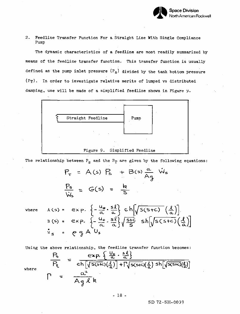
2. Feedline Transfer Function For a Straight Line With Single CompliancePump
The dynamic characteristics of a feedline are most readily summarized by
means of the feedline transfer function. This transfer function is usually
defined as the pump inlet pressure (Ps) divided by the tank bottom pressure
(FT). In order to investigate relative merits of lumped vs distributed
damping, use will be made of a simplified feedline shown in Figure y.
Straight Feedline Pump
Figure 9. Simplified Feedline
The relationship between Pg and the Pip are given by the following equations:
PT = ACs) R, -*• &(*£-
-I-L = GO) =Ws
where A C . ) - ex {- £ - fA '(*)]•
•W A u,
Using the above relationship, the feedline transfer function becomes;
chwhere
r -- 18 -
SD 72-SH-0039
Space DivisionNorth American Rockwell
When using the single compliance model the following constants were used.
Ji. , o-'' "a, •r± - .,006a.
= C,:A.G8
M/ (30.H8K.)
, ooo JH.- ( 5-07 J :Sec, V sec
The transmission parameters previously considered had the damping distributed
along the line segment. An alternate procedure is to lump the damping at the
ends of elemental sections of the feedline. The pressure loss due to damping
in a section of the feedline is given by the following expression:
p = - $ Aa P_L _ a>rt ' a
The linear perturbation equations may be obtained by removing the steady state
terms. The resulting equations for the perturbed values of pressure and
velocity are given below:
AP = - C/
c =D
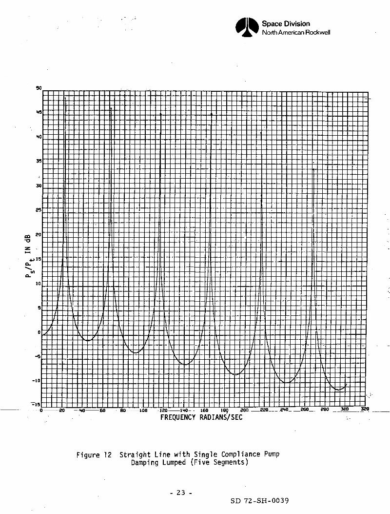
In order to compare lumped with distributed damping, Bode plots of the feedline
transfer function were obtained for an n-segmented line with lumped damping.
These results were compared with the "exact" solution using distributed
- 19 -SD 72-SH-0039
Space DivisionNorth American Rockwell
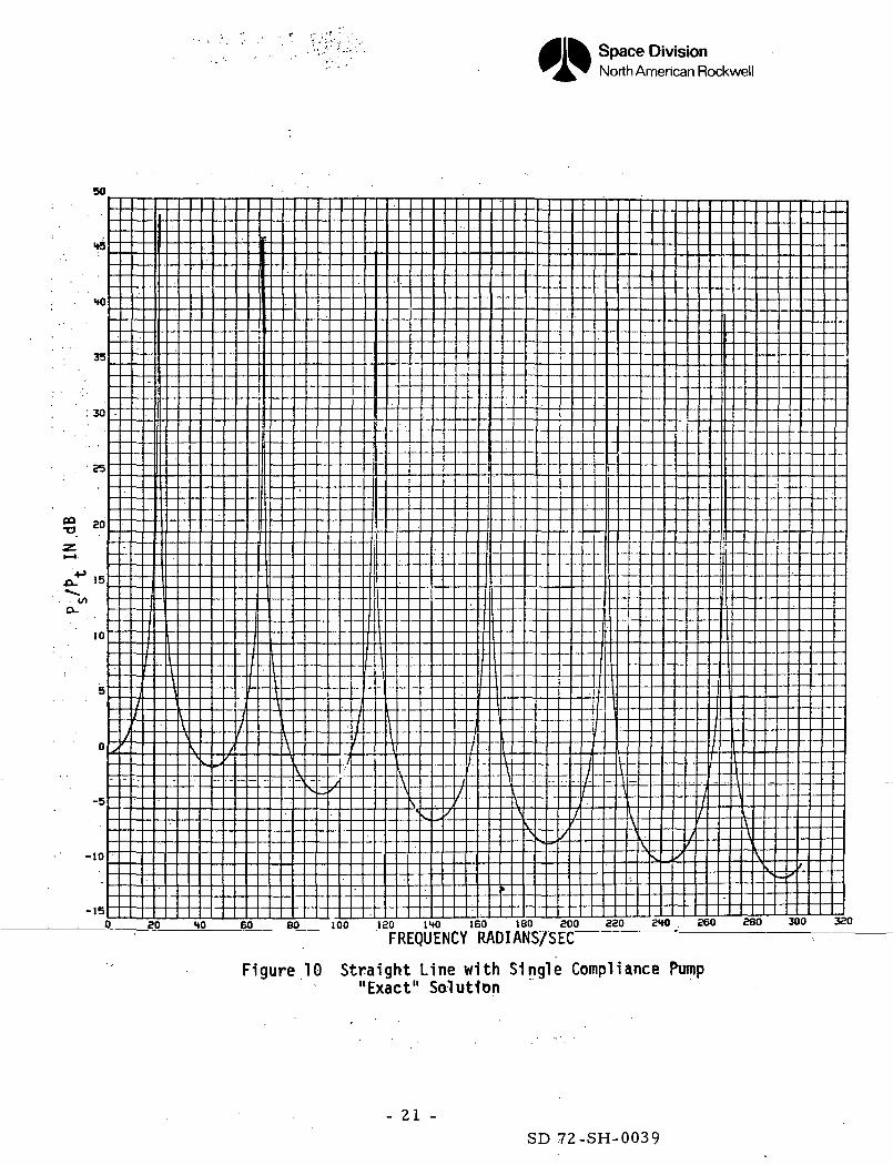
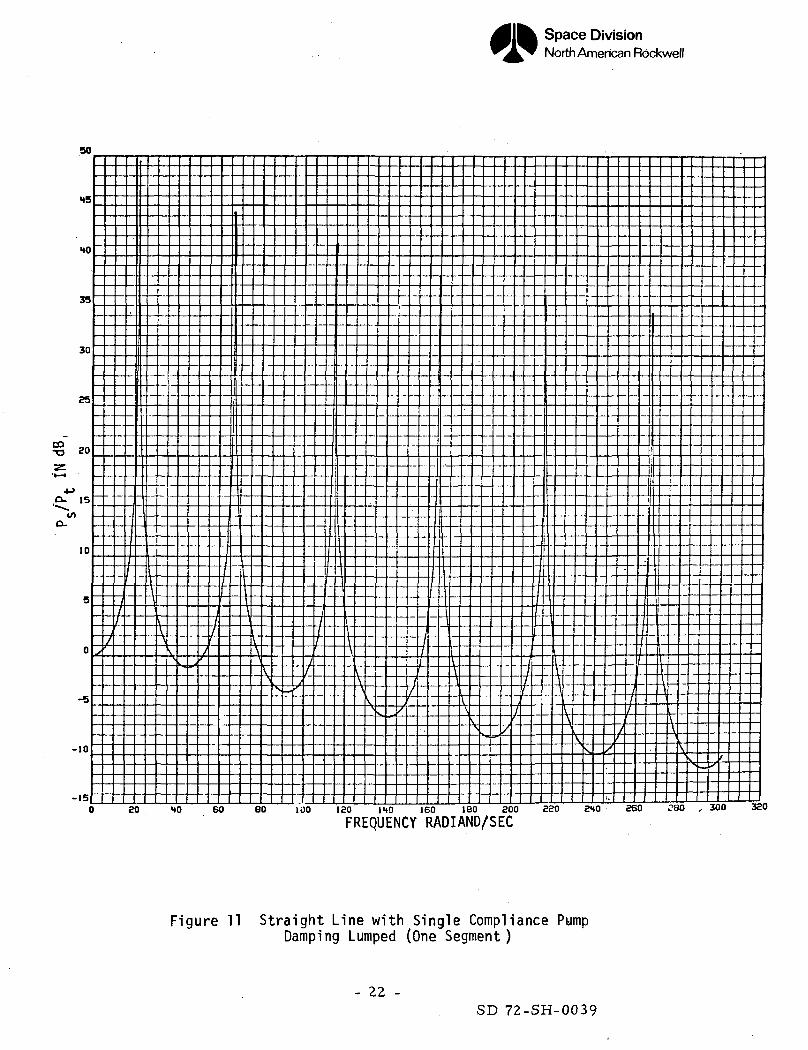
damping. Two typical runs using lumped damping for n = 1 and 5 are shown in
Figures 11 and 12 and may be compared with the case of distributed damping
shown in Figure 10. The results are seen to be identical except for the peak
gains.
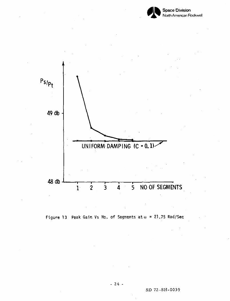
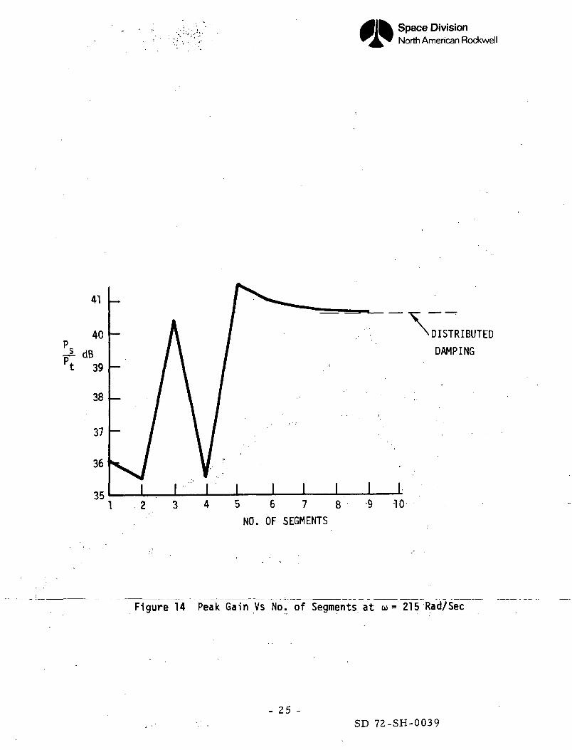
The effects of the length of elemental sections on the error have been shown
graphically for the peak gains at the first and fifth peaks in Figures 13 and
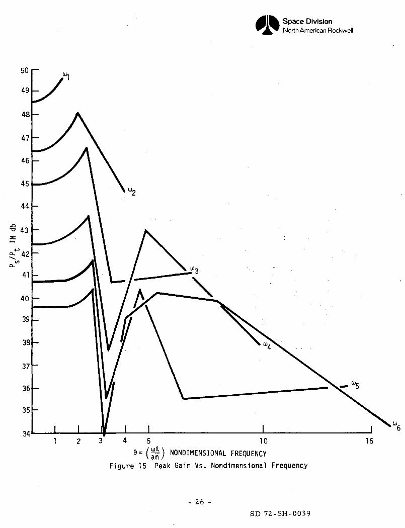
. lU. A more informative curve may be obtained by plotting peak gains rs/p*(j O
vs nondimensional frequency 6 where © = —-. This curve (Figure 15) shows•O'V CC
that in the frequency range of interest, the error is acceptable provided ©<
It should be noted that ©-O corresponds to distributed damping.
- 20 -
SD 72-SH-0039
Space DivisionNorth American Rockwell
50
HO
35
'. 30
CO-o
10
-10
-15_o so HO eo eo Too leo IHO ieo iso aoo aao 240 eeo seo soo aao
'FREQUENCY RADIANS/SEC"
Figure 10 Straight Line with Single Compliance Pump"Exact" Solution
- 21 -SD 72-SH-0039
Space DivisionNorth American Rockwell
-15o so to eo eo Too lao IHO ieo ieo zoo sso eno aeo ?ao , 300 3ao
FREQUENCY RADIAND/SEC
Figure 11 Straight Line with Single Compliance PumpDamping Lumped (One Segment)
- 22 -SD 72-SH-0039
Space DivisionNorth American Rockwell
TTT TTT TTT TTT
HO
35
so
10
-10
0 80 -HO 60 80 100 120 IHO 160 189 200 220 240 260 280 300 320
FREQUENCY RADIANS/SEC
Figure 12 Straight Line with Single Compliance PumpDamping Lumped (Five Segments)
- 23 -SD 72-SH-0039
Space DivisionNorth American Rockwell
>S/Pt
49 db-
48 db
UNIFORM DAMPING (C
1 2 3 4 5 N O O F SEGMENTS
Figure 13 Peak Gain Vs No. of Segments at w = 21.75 Rad/Sec
- 24 -
SD 72-SH-0039
Space DivisionNorth American Rockwell
41
40>
't 39
38
37
36
35
\DISTRIBUTED
DAMPING
I I I I I
1 . 2 3 4 5 6 7 8 9 1 0NO. OF SEGMENTS
Figure 14 Peak Gain Vs No. of Segments at o> = 215 Rad/Sec
- 25 -SD 72-SH-0039
Space DivisionNorth American Rockwell
4 5 1 09 = ( a n ) NONDIMENSIONAL FREQUENCY
Figure 15 Peak Gain Vs. Nondimensional Frequency
15
- 26 -
SD 72-SH-0039
Space DivisionNorth American Rockwell
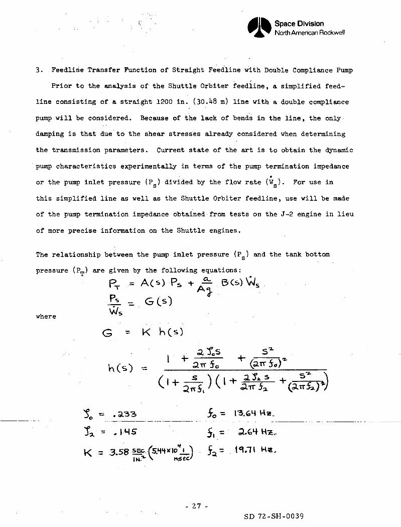
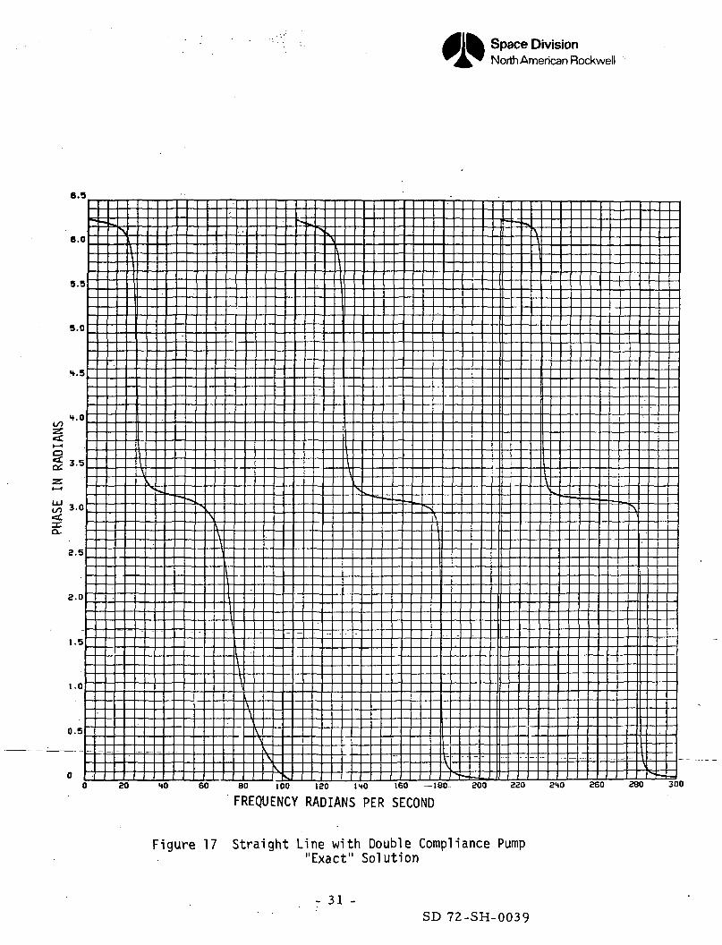
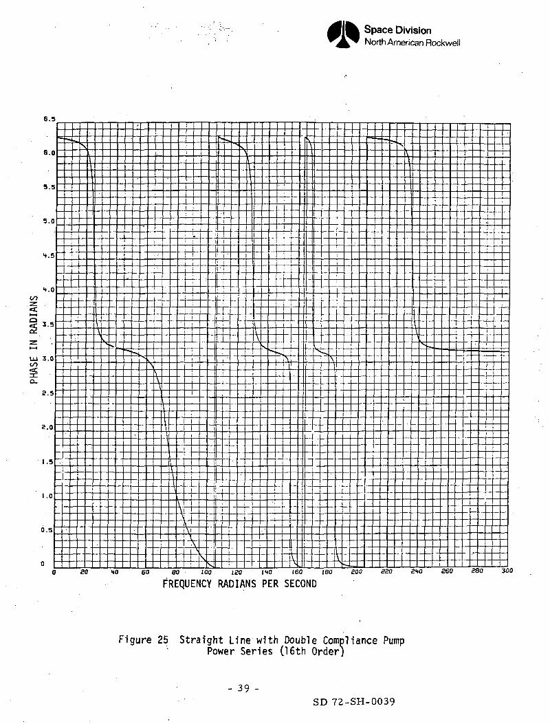
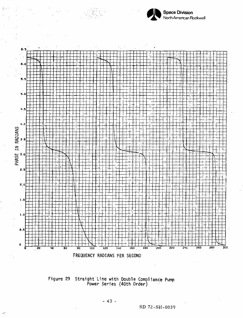
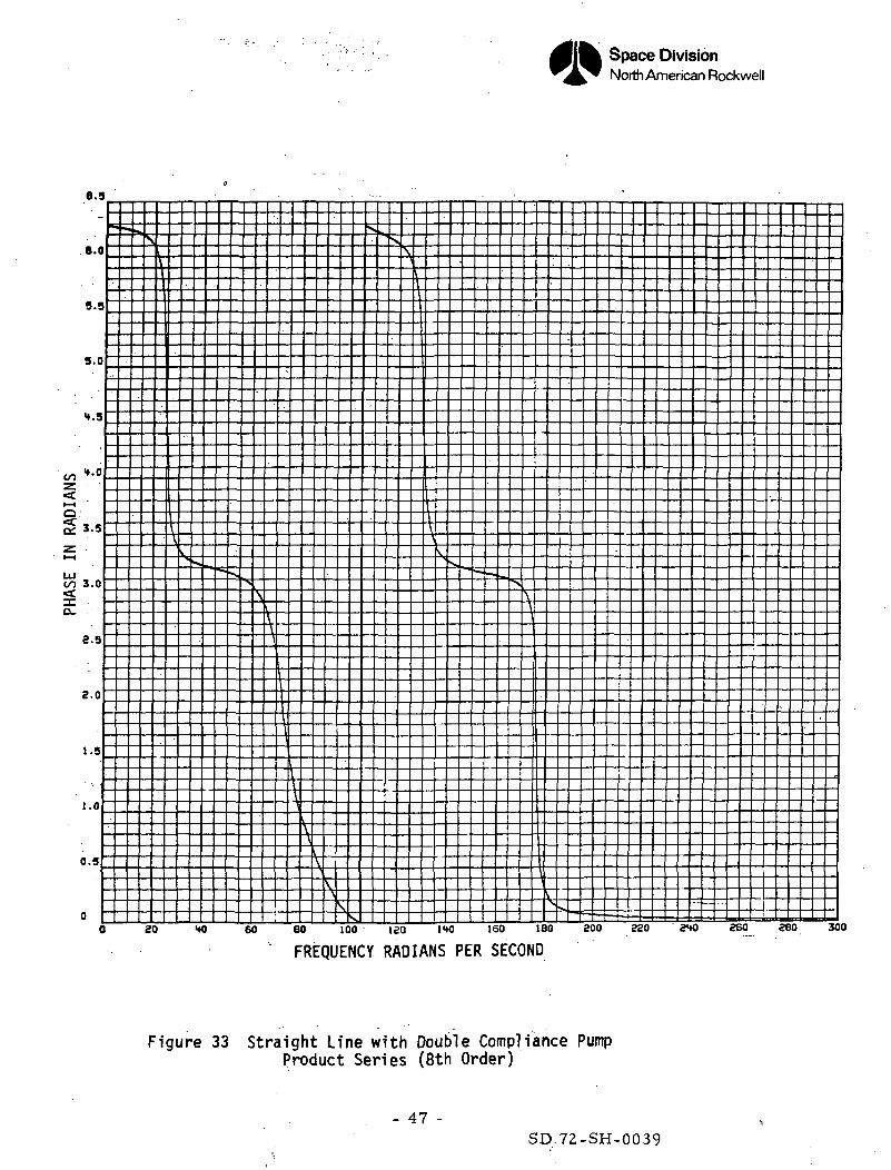
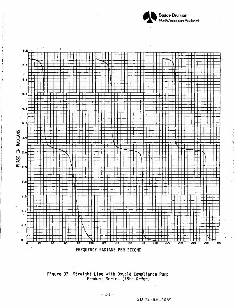
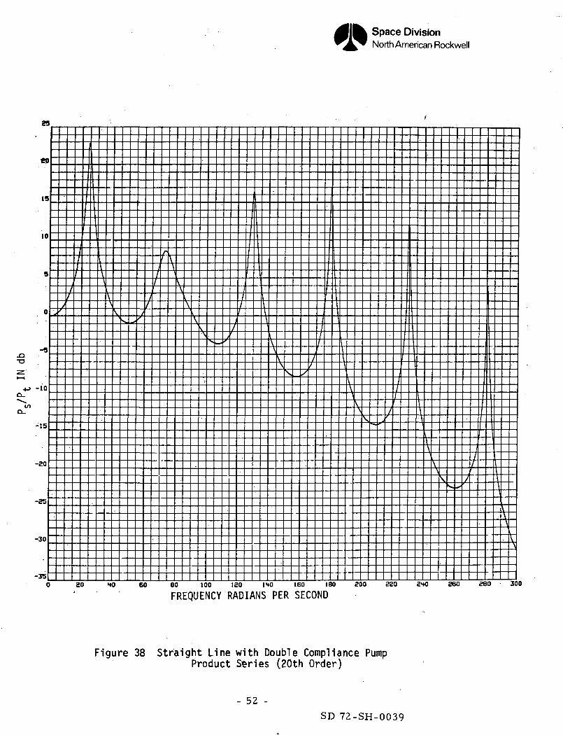
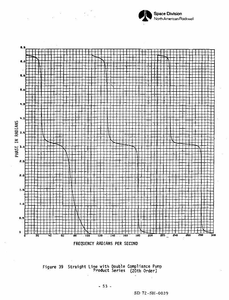
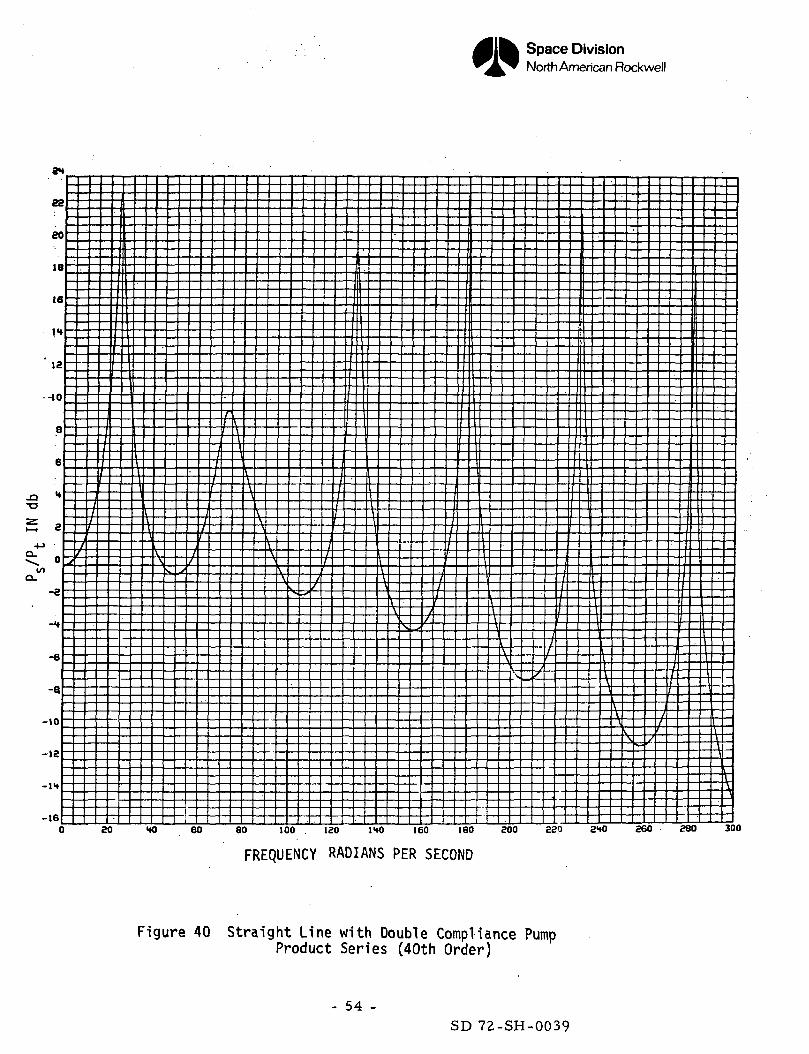
3. Feedline Transfer Function of Straight Feedline with Double Compliance Pump
Prior to the analysis of the Shuttle Orbiter feedline, a simplified feed-
line consisting of a straight 1200 in. (30.U8 m) line with a double compliance
pump will be considered. Because of the lack of bends in the line, the only
damping is that due to the shear stresses already considered when determining
the transmission parameters. Current state of the art is to obtain the dynamic
pump characteristics experimentally in terms of the pump termination impedance
or the pump inlet pressure (P ) divided by the flow rate (W ). For use inS S
this simplified line as well as the Shuttle Orbiter feedline, use will be made
of the pump termination impedance obtained from tests on the J-2 engine in lieu
of more precise information on the Shuttle engines.
The relationship between the pump inlet pressure (P_) and the tank bottomS
pressure (Pm) are given by the following equations:
RT = AO) PS -t-^ 5Cs)VJs
%L - GOOVvswhere
G = K K(s)
a T s s^
5, - S.64 Hz,
3.58 sEc/5.H4«io 5 =IN* V
- 27 -SD 72-SH-0039
Space DivisionNorth American Rockwell
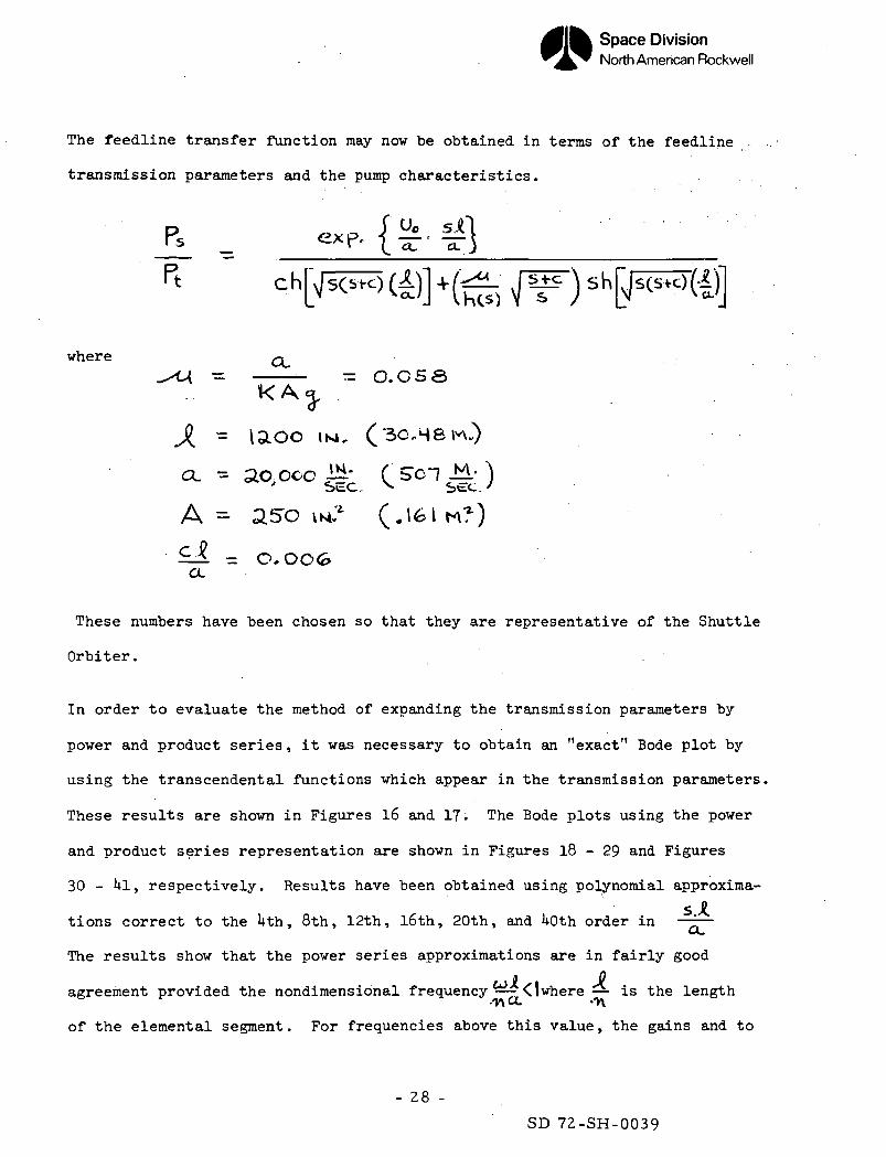
The feedline transfer function may now be obtained in terms of the feedline
transmission parameters and the pump characteristics.
where Q- - O.C5S
K A 3-M, ( 30,48
A = a50 \H? (.161 M?
i-l = O.OOGCL
These numbers have been chosen so that they are representative of the Shuttle
Orbiter. .
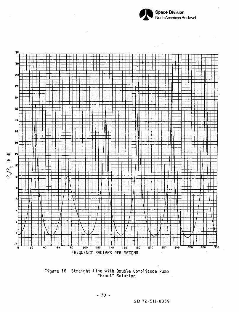
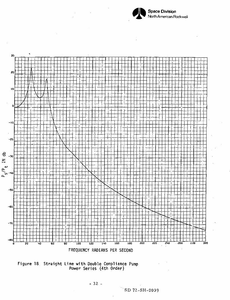
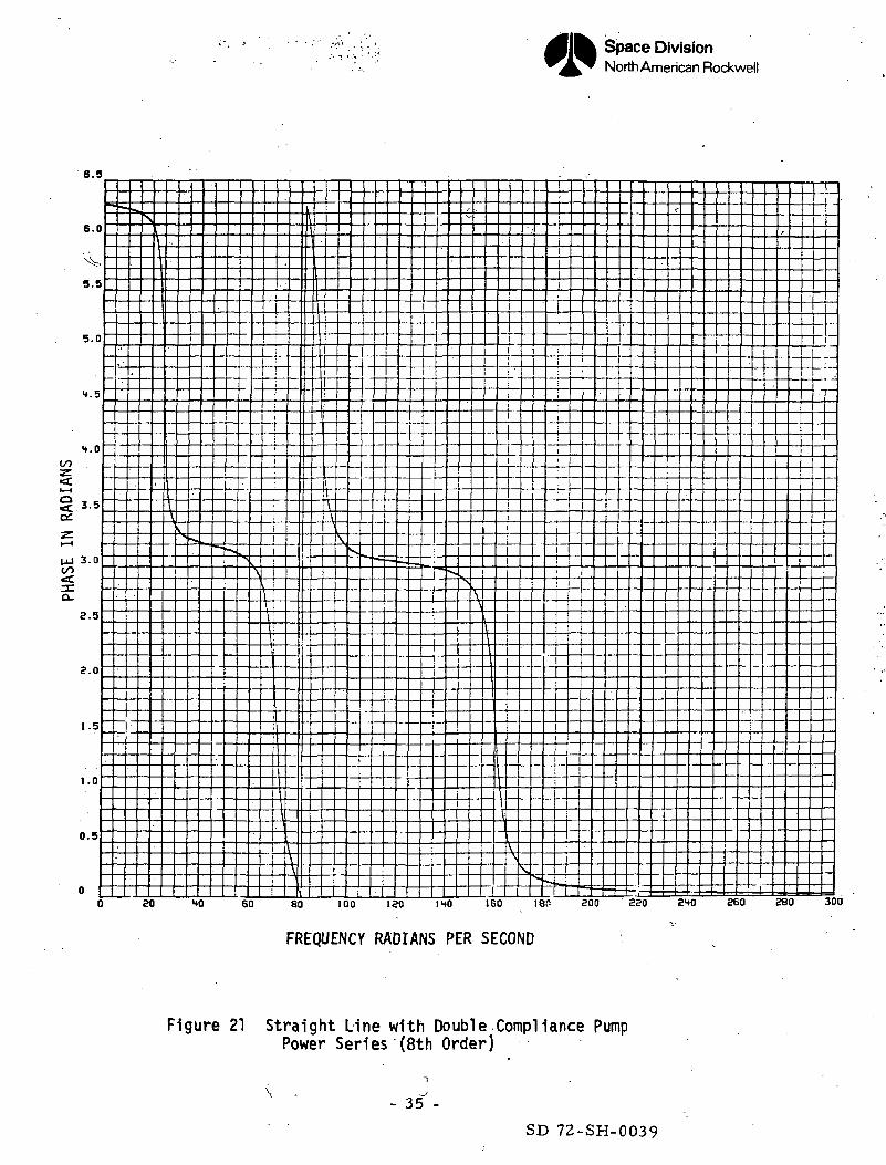
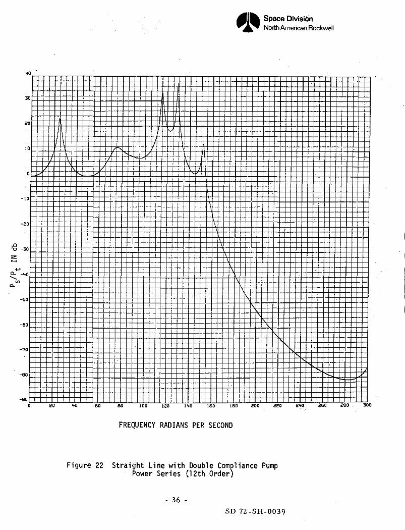
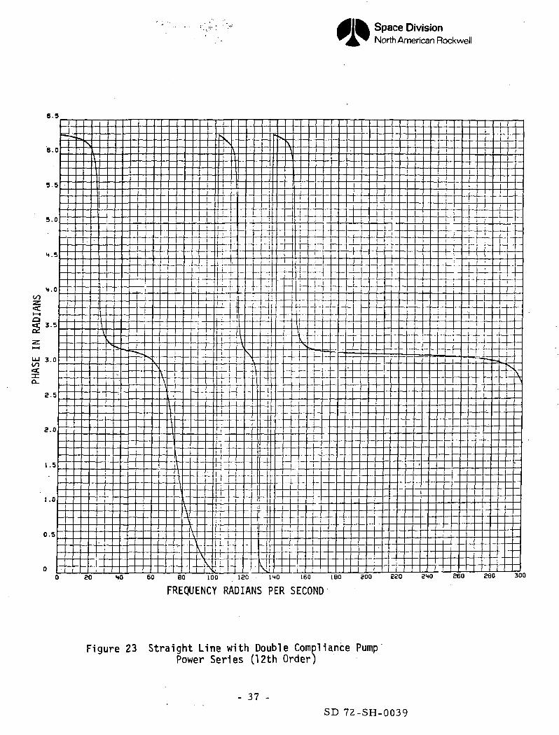
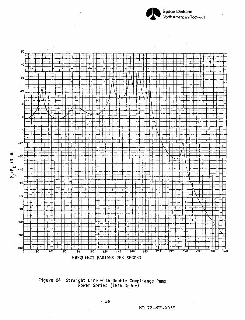
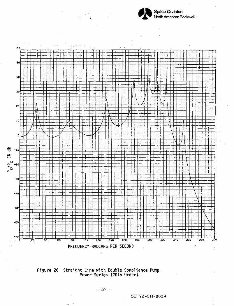
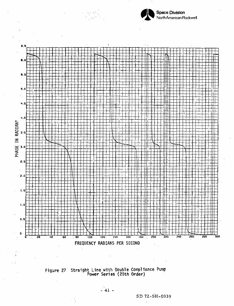
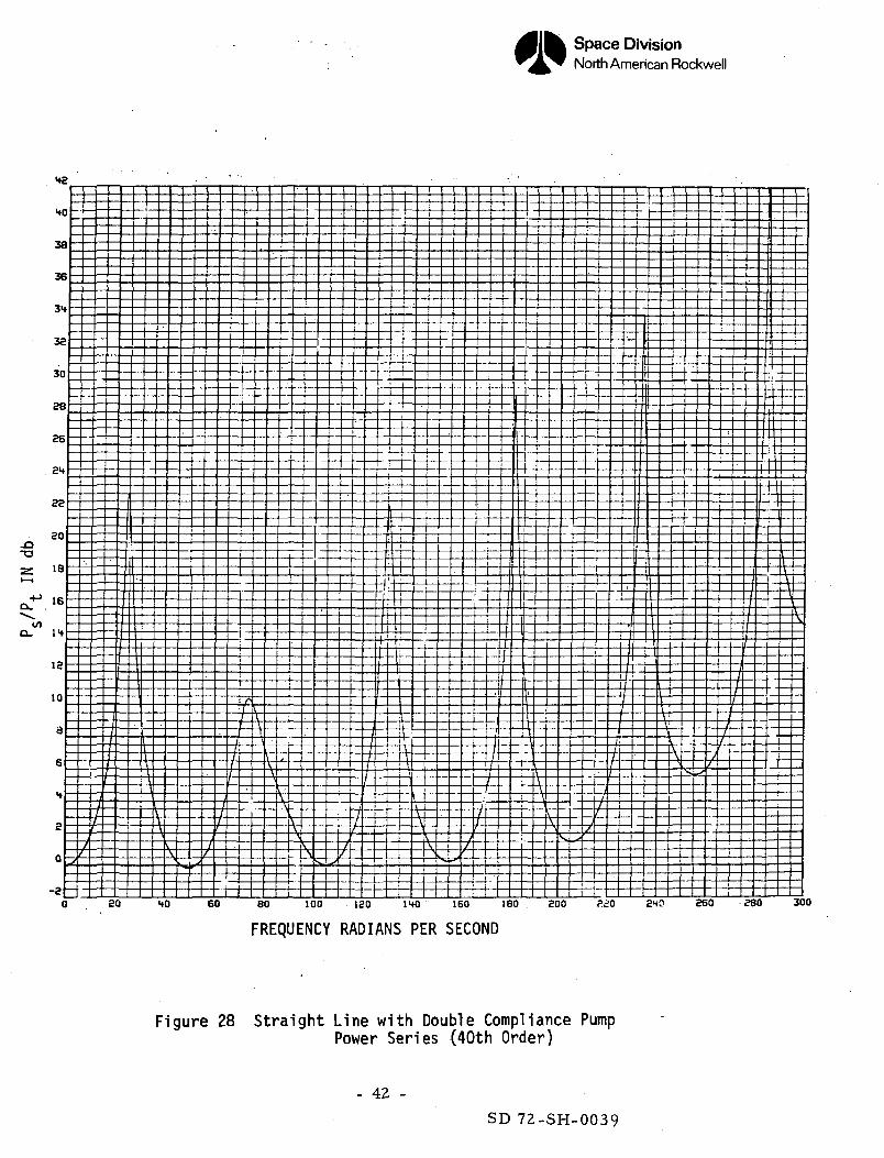
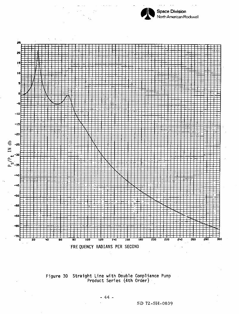
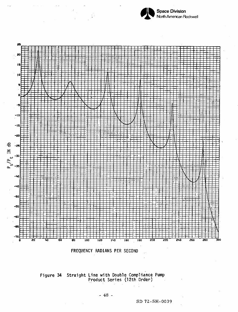
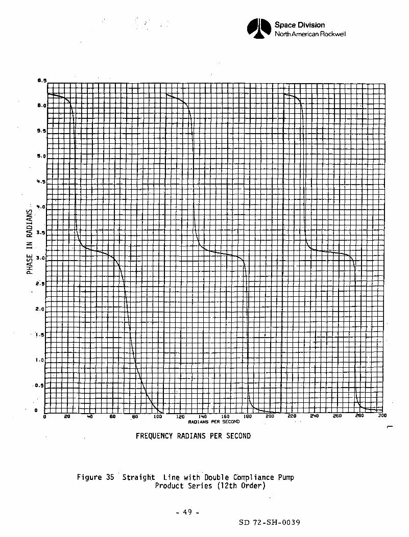
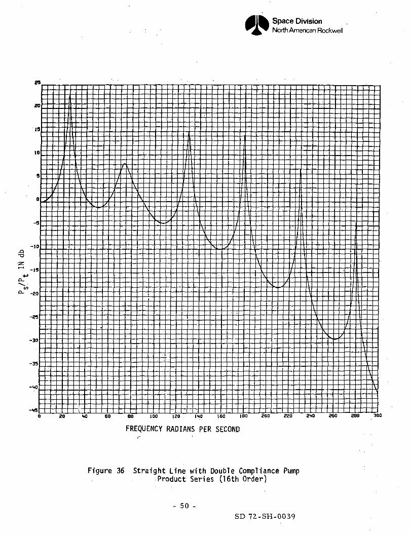
In order to evaluate the method of expanding the transmission parameters by
power and product series, it was necessary to obtain an "exact" Bode plot by
using the transcendental functions which appear in the transmission parameters.
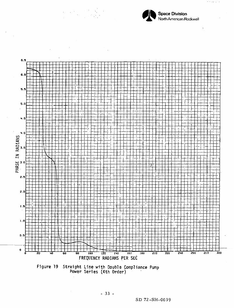
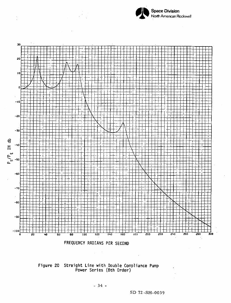
These results are shown in Figures 16 and IT. The Bode plots using the power
and product series representation are shown in Figures 18 - 29 and Figures
30 - Ul, respectively. Results have been obtained using polynomial approxima-
tions correct to the Itth, 8th, 12th, l6th, 20th, and Uoth order in '
The results show that the power series approximations are in fairly good
agreement provided the nondimensional frequency < where — is the length* f\
of the elemental segment. For frequencies above this value, the gains and to
- 28 -
SD 72-SH-0039
Space DivisionNorth American Rockwell
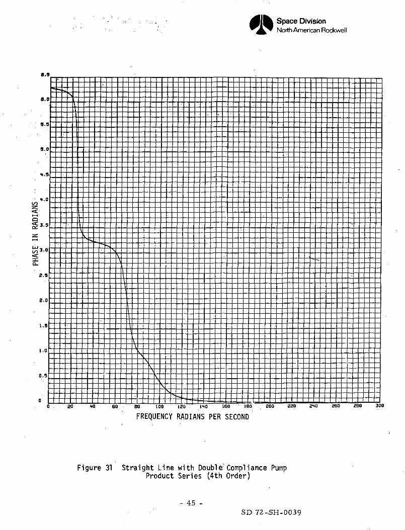
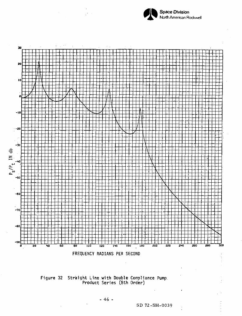
a larger extent the phase, begin to vary from the "exact" solution. The
product series solutions of the same order have about the same accuracy as the
power series results up to the 8th order. The higher order solutions, however,
are not as satisfactory. The gain curve tends to slope downward. This can be
explained by looking at the product series expansions of the hyperbolic cosine
curves given in Figures 3-8. The product expansion of the hyperbolic cosine
(as well as the hyperbolic sine, not shown) have errors which increase the
gain at the higher frequencies. Since these terms appear in the denominator
of the transfer function PS/PIJI they have the effect of reducing the gain at
higher frequencies.
\
- 29 -SD 72-SH-0039
Space DivisionNorth American Rockwell
22
18
16
14
12
to10
40 60 80 100 120 140 160 180 200 220 240 260 280 300
FREQUENCY RADIANS PER SECOND
Figure 16 Straight Line with Double Compliance Pump"Exact" Solution
- 30 -SD 72-SH-0039
Space DivisionNorth American Rockwell
6.9
6.0
5.5
5.0
1.5
H.O
^i— ig^ 3.5
Zt—i
LUCO 3.0«c3;
2.5
2.0
1.5
1,0
0.5
0
\
^ *x***,
^\
\
\
I\\
-
\
-
\
\
^
- -
!
1
4\
^*™ • •*••
-
-«.S
— -\
_
- —
r
-•
* ^
- — -- _
5
- (
20 60 60 100 120 140 160 —180. 800 230 240 260 300
FREQUENCY RADIANS PER SECOND
Figure 17 Straight Line with Double Compliance Pump"Exact" Solution
- 31 -SD 72-SH-0039
Space DivisionNorth American Rockwell
30
so
to
0
-10
-20
-Q"° -30zh— t
4->Q.
w-HQQ-
-50
-€Q
-70
-80
0
|
I1
/
/f
at
1A
/ •
j
iii
,\V\
HI
/
}
A
f/
/
|
4
\
\r- r
!
60
_j
\
V — 1\
^
80
1
1,
^\
"^
i
[
1 '
. .1
i
i
\
i^.\
100
1 rrIIi
| j;
1
I1
^>
sl>^"T X
>20 1W
1 1
(I
I i
-L-L -11!
_
1
" "T ' ~ I
4^^cS. . 1
"Ss.*s
^x ."^^x
•^^
160 180 200 220
J_
[_
S i ' —^^~ •*'
"^-v^
" .,
^f5^• • "°>~
2HO 260 £30 300
FREQUENCY RADIANS PER SECOND
Figure 18 Straight Line with Double Compliance PumpPower Series (4th Order)
- 32 -SD 72-SH-0039
Space DivisionNorth American Rockwell
6.3
6.0
5.3
5.0
"4.5
GO
3.5
LiJ 3.0CO
. 5
2.0
1.5
I.O
0.5
80 40 60 60
4-11•f
100 lao IHO leo leo aoo eao 2to eso 300
FREQUENCY RADIANS PER SEC
Figure 19 Straight Line with Double Compliance PumpPower Series (4th Order)
- 33 -
SD 72-SH-0039
Space DivisionNorth American Rockwell
30
10
-10
-20
-30
-10
_l
-50
-60
-70
-80
-90
-1000 80 HO 60 BO 100 ISO
FREQUENCY RADIANS
mo 160 IEJ aoo 320 210 seo SBO 300
PER SECOND
Figure 20 Straight Line with Double Compliance PumpPower Series (8th Order)
- 34 -
SD 72-SH-0039
Space DivisionNorth American Rockwell
8.9
6.0
3.5
5.0
_L ::r:4.5
H.O00
I3- 'LU 3.0oo<c
2.5
2.0
1.5
1.0
0.5
20 HO 60 80 100 120 160 180 200 220 2HO
FREQUENCY RADIANS PER SECOND
Figure 21 Straight Line with Double Compliance PumpPower Series (8th Order)
- 35 -
280 300
SD 72-SH-0039
Space DivisionNorth American Rockwell
30
20I
I ,t\ -L- -" _ J_.
; Vf \ i iZ" ^ 7
( ^X ^ _;?
-10!i
-20 !
•° , -L-t-T3 -30r y - . . . .i— i
•MQ- -HO
I/)o.
-50
-60_|
-70
-80
-900 20 40 60
r i ' ' • " ~i
1 11 (Im ly
• i 1 JJI I I I
/ / I1 / 1/ \ n
*J \1
1 I \1 1 A
/S ' J I i-^ ^^^Zu ! _t J. IT/ ! V
^ /^_ /\./i1
. . . _ _ . . \\T
,
\\
\ ' "
_u t
N,r \
*Sv.... . V
s^I _ S
I
I _L
80 100 180 140 . 160 180 800
i
•I
\\
!Sx
x^ s
S^ J
ia^ ^
880 340 260 380 . 300
FREQUENCY RADIANS PER SECOND
Figure 22 Straight Line with Double Compliance PumpPower Series (12th Order)
- 36 -SD 72-SH-0039
Space DivisionNorth American Rockwell
6.51
"*— "^ ^_
6.0
5.5
5.t _i_
1.5
1.0
3.5
3.0|t
2.5
2.0
1.5
1.0
0.5
0
|
j1 ''
,
\3 I
V
|
0 20 10
j
-^
i
\c
. A
^ tt
"H
,_l tit ij
i
i
i
An
V
\\;_
ii
>J
:: Et" ti i . :
i ] !
1! !
- ! !
j • 1
L i!
! !" I f
!1 1 i
:! T _L
— t~r~ \ 'i i 1 \ \: (
, ;i !
ii ii ii. 1 ...
<' ! i
iii
i ' 1
-L Ii i_l_ _ii I
t ~ " i1 r 1 j
j i
• i i; .
; j |i l i j
TT " f~\U
>^\
: 3
iiii
ii iT iL. _(-- -i ..l a -^-T--I' - -r-
i
!l-A
i ti
i
i i1
|
ii.60 80 100 120 1HO 160 160
FREQUENCY RADIANS PER SECOND
--
1
l1tfIjI
i•
i
I
j
I (1 ,j. ..
|
1
i
1
1
1I
1} i
iI
i
I
^»
f
T!
_i_
-4.
U-
!1
"1
N.S
200 220 240 260 280 300
oo
»-H
O
Figure 23 Straight Line with Double Compliance PumpPower Series (12th Order)
- 37 -
SD 72-SH-0039
Space DivisionNorth American Rockwell
5C
HO
30
SO
to
0
-10
-SO
-30
-to
-50
-60
-70
-80
-90
-1000
S
4 -ft
J
/
80
V\
S,^
MO
•vX
60
2/
8(
's
(
j
^
•'
i
,
L?
too
1
1' ft
/ \A J, {_
J vt?/
i /
/I/
— •** *
\
\\
\
leo mo
i. I
f "~/ •- T-L Z^
1. ~J~.t\
- - - \ J
\ 7v/ ifi
._ " ~ \\\- \ i\_. i \^ T \
\
j V
1
j
1
1I
1j- - - ) _ -
._ -t
160 180 200
i
jL
520
.
i
!
1
it
1 /II I
' / 'i/ yIZL1"^^ i
; \3i '
r \x>
\
y
\.
1
1
!
2*0 260
j
t)
_
i •. |
it. _tzri^
\
•A .\J
v\
S^\
\^
. 380 300
FREQUENCY RADIANS PER SECOND
Figure 24 Straight Line with Double Compliance PumpPower Series (16th Order)
- 38 -SD 72-SH-0039
Space DivisionNorth American Rockwell
6.5
6.0
5.5
5.0
>t.5
H.OGO2:<:r-jS 3.5a:
LD 3.0t/>
-pQ.
e.s
a.o
1.5
1.0
0.5
00
I
|
>>
SO
\\
^ s
Ito
"
r
*"X^
6
\
1
s\\
\\\
sc
\\'
)
i
ii1
\\\
1
«
\\s10
1
V
0
•»* .
' iii
• !
i
i
I
1
I
IS
V
0
\\^
1»*
^
0
^>V
\\160
s
I
'sK.
le
S
\
0s^
£00
1
£30
•v.i
V
T
2M0 ZbU
r—
HU
.|1
— _ _
|
U
1,
30t
FREQUENCY RADIANS PER SECOND
Figure 25 Straight Line with Double Compliance PumpPower Series (16th Order)
- 39 -SD 72-SH-0039
Space DivisionNorth American Rockwell
60
so
30
20
10
-o -10•z.I—I
4->OL -20
O_
-30
-40
-50
-60
-70SO HO 60 60 10'J 120 140 160 180 200 220 240 260 280 300
FREQUENCY RADIANS PER SECOND -
Figure 26 Straight Line with Double Compliance PumpPower Series (20th Order)
- 40 -
SD 72-SH-0039
Space DivisionNorth American Rockwell
6.5
6.0
5.5
5.0
1.5
t.Ot/.Zt-HQ< 3.5a:•yHH
^ 3.0«CQ-
8.5
S.O
J.5
1.0
0.5
00
~ V
e
I .\11
1I
i
V
X ^^
H(J
->.
60
V _
\\1
\
'
i1
\
\
\
, e
\\
D
\
\
^
100 IS
^
0
\
}
_l
\^^
1101
16
••
0
1
^N
\
I
|
I,| V
IS^0 z
y" ,
00
\
,
[_
^ 1Zi
^^*
0 2H
"•fc
0
^
V^*
Zb••-*,
0^r
1—
!
zs_L0
!|
|
|
—
1|
30(
FREQUENCY RADIANS PER SECOND
Figure 27 Straight Line with Double Compliance PumpPower Series (20th Order)
- 41 -
SD 72-SH-0039
Space DivisionNorth American Rockwell
20 tO 60 80 100 IZO 110 160 180 200 P.20 240 260 280 300
FREQUENCY RADIANS PER SECOND
Figure 28 Straight Line with Double Compliance PumpPower Series (40th Order)
- 42 -
SD 72-SH-0039
Space DivisionNorth American Rockwell
6.9
6.1
5.!
.{
3.5i
UJ 3.0
Z. 5
a.o
1.5
1.0
0.5
5
20 HO 60 80 100 120 ItO 160 180 200 220
FREQUENCY RADIANS PER SECOND
Figure 29 Straight Line with Double Compliance PumpPower Series (40th Order)
260 280 300
- 43 -
SD 72-SH-0039
Space DivisionNorth American Rockwell
25
80
IS
10
-10
-15
-20
-Q-u -25
-30-MQ__
O. -35
-10
-H5
-50
-60
-70HO 60 80 100 120 1HO 160 180 800 220 2HO 260 280 300
FREQUENCY RADIANS PER SECOND
Figure 30 Straight Line with Double Compliance PumpProduct Series (4th Order)
- 44 -
SD 72-SH-0039
Space DivisionNorth American Rockwell
6.9
8.1
S.S
5.(
"».!
• H.OCO
i— iQj5 3.5
•ZL\ — i
iiiCO3'0
'JL.
a. s
8.0
1.5
1.0
0.5
00
- :
16 •• s
r1i
*M1[\111 1
11IfItIt|I1
.it _qr .JL .r .r ._i .
T
'
^ >,
"
'
30 HO 60
~1
3>Isjj
BO
^
100
•«= ~— _ — ••
•
i i n.
.
—
120 1HO 160 180 300 820 2t*0 260 280 300
FREQUENCY RADIANS PER SECOND
Figure 31 Straight Line with Double-Compliance PumpProduct Series (4th Order)
- 45 -
SD 72-SH-0039
Space DivisionNorth American Rockwell
30
10
-10
-ao
-30
-toCL.
-50
-60
-70
-BO
-90o ao HO eo eo too lao \w ieo ieo aoo aao ato aeo aeo 300
FREQUENCY RADIANS PER SECOND ;
Figure 32 Straight Line with Double Compliance PumpProduct Series (8th Order)
SD 72-SH-0039
Space DivisionNorth American Rockwell
6.9
6.0
9.9
9.0
H.!
<i—iO
3-5
UJ00 3.0
a.9
2.0
t.s
1.0
o.s
aO HO 60 80 100 180 1HO 150 ISO 200 E20 260 sea 300
FREQUENCY RADIANS PER SECOND
Figure 33 Straight Line with Double Compliance PumpProduct Series (8th Order)
- 47 -SD 72-SH-0039
Space DivisionNorth American Rockwell
-10
-15
-20
-0 -25
zI—I
^-30Q_
>-35
-HO
-H5
-50
-60
-65
-7020 40 60 80 100 150 140 160 180 200 220 2HO 260 280 300
FREQUENCY RADIANS PER SECOND
Figure 34 Straight Line with Double Compliance PumpProduct Series (12th Order)
- 48 -
SD 72-SH-0039
Space DivisionNorth American Rockwell
B.9
9,5
9.0
4.5
H.OOO
«CHHo
3.0IS)
8.0
1.5
1.0
0.5
0 80 40 60 80 >00 120 1HO 160 180 200 220 2HO 260 280 300RADIANS PCR SECOND
FREQUENCY RADIANS PER SECOND
Figure 35 Straight Line with Double Compliance PumpProduct Series (12th Order)
- 49 -
SD 72-SH-0039
Space DivisionNorth American Rockwell
to
-10,0-o
-15•M
O-
-as
-30
-35
-40
-H580 HO 60 80 100 130 140 160 180 500 £50 540 260 380 300
FREQUENCY RADIANS PER SECOND
Figure 36 Straight Line with Double Compliance PumpProduct Series (16th Order)
- 50 -SD 72-SH-0039
Space DivisionNorth American Rockwell
6.5
6.0 V
3.3
9.0
1.5
4.0
CO,
:3.0
to
8.3
8.0
1.3
1.0
0.9
0 80 40 60 80 100 ISO 1HO 160 ISO- 200 820 2HO 260 280 300
FREQUENCY RADIANS PER SECOND
Figure 37 Straight Line with Double Compliance PumpProduct Series (16th Order)
- 51 -SD 72-SH-0039
Space DivisionNorth American Rockwell
as-J-4-4- -Uul
19
10
JD•o
4J -10D_
-15
-SO
-as
-30
-3580 >*0 60 60 100 ISO 1HO 160 180 200 ZSQ SHO 260 S80 300
FREQUENCY RADIANS PER SECOND
Figure 38 Straight Line with Double Compliance PumpProduct Series (20th Order)
- 52 -SD 72-SH-0039
Space DivisionNorth American Rockwell
e.s
6.0
9.5
5.0
H.Oco
«C
3.-
UJ 3.0oo<C.
2.5
2.0
1.5
1.0
0.5
20 >»0 60 60 100 120 160 160 200 820 2HO 260 280 300
FREQUENCY RADIANS PER SECOND
Figure 39 Straight Line with Double Compliance PumpProduct Series (20th Order)
- 53 -SD 72-SH-0039
Space DivisionNorth American Rockwell
2M
88
80
18
16
—10
-6
-a
-10
-12
-it
-16 rrrSO HO 60 80 100 . ISO 1HO 160 180 ZOO 220 2HO 260 280 300
FREQUENCY RADIANS PER SECOND
Figure 40 Straight Line with Double Compliance PumpProduct Series (40th Order)
- 54 -
SD 72-SH-0039
Space DivisionNorth American Rockwell
6.9
K "• .,
e.o
9.!
9.0
H.9
H.O
3.9
3.0
8.9
8.0
1.9 "
1.0 ~
0.9 ~
0 '
0
1
80 HO
^
60
x to
— _ ^ — —
_ _ t- -
~\
"
.\V1flIT1 1I1jl|In'\\I'
4 :\
T
V. v1 1 1 1 1 1 "NJ 1 1 1 1 1 1 1 1 1 1 1 1 1 1 1 1
80 100 120 110 160 180
= •• ^ST
V•^ K
= -,
"V
200 280 2HO 860 2SO 300
in
<cn:Q_
FREQUENCY RADIANS PER SECOND
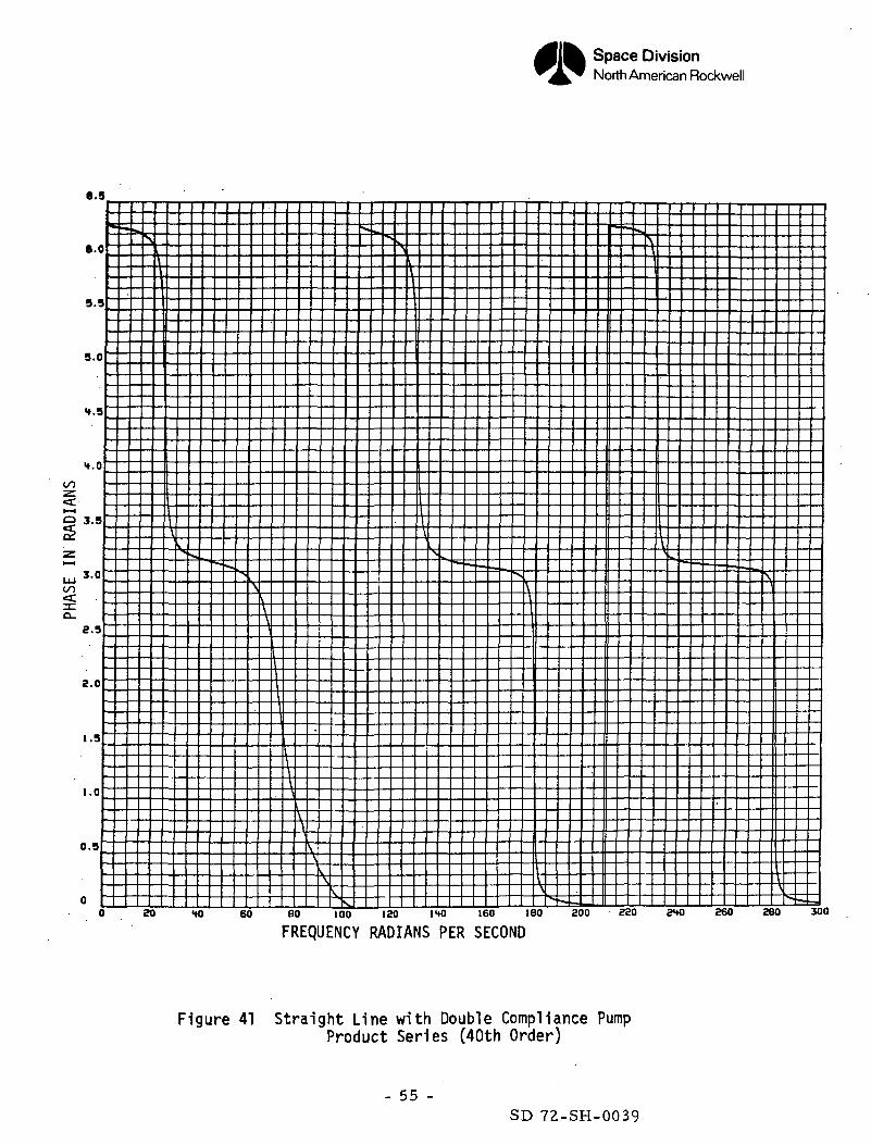
Figure 41 Straight Line with Double Compliance PumpProduct Series (40th Order)
- 55 -SD 72-SH-0039
Space DivisionNorth American Rockwell
IV. SHUTTLE ORBITER FEEDLINE
1. Modeling
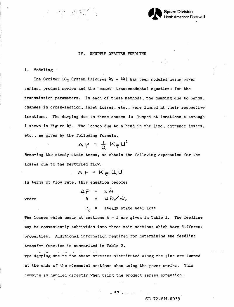
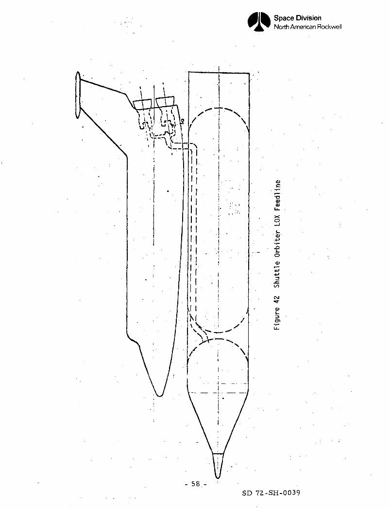
The Orbiter L02 System (Figures 1*2 - UU) has been modeled using power
series, product series and the "exact" transcendental equations for the
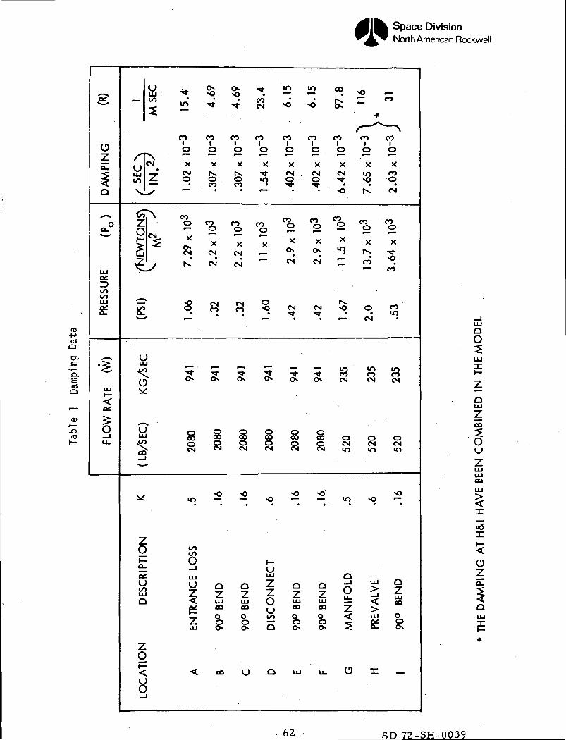
transmission parameters. In each of these methods, the damping due to bends,
changes in cross-section, inlet losses, etc., were lumped at their respective
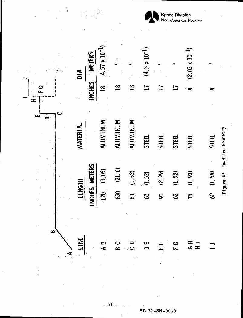
locations. The damping due to these causes is lumped at locations A through
I shown in Figure 1*5- The losses due to a bend in the line, entrance losses,
etc., as given by the following formula.
*p = i K>UIRemoving the steady state terms, we obtain the following expression for the
losses due to the perturbed flow.
A p - K e u*aIn terms of flow rate, this equation becomes
A p = R W
where R = 3. P0/W0
P = steady state head loss
The losses which occur at sections A - I are given in Table 1. The feedline
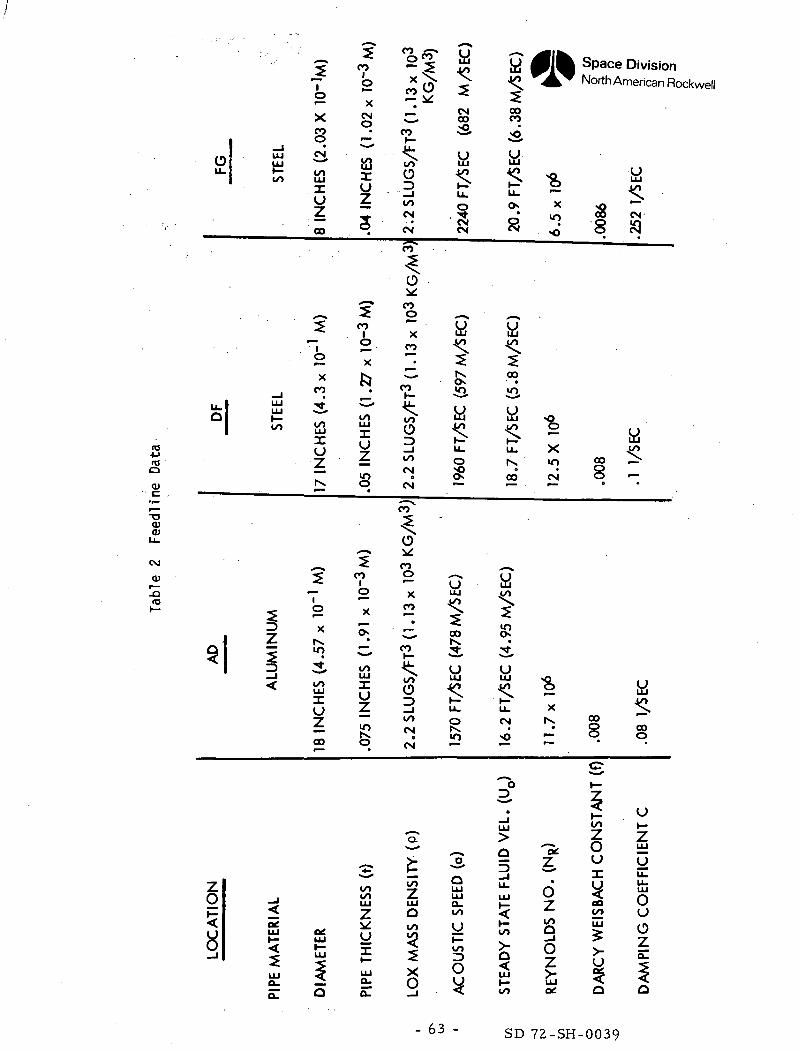
may be conveniently subdivided into three main sections which have different
properties. Additional information required for determining the feedline
transfer function is summarized in Table 2.
The damping due to the shear stresses distributed along the line are limned
at the ends of the elemental sections when using .the power series. This
damping is handled directly when using the product series expansion.
- 57'-.,.
SD 72-SH-0039
Space DivisionNorth American Rockwell
-aaiQi
xo
i.0)
i.O
0)
CM
0)
30)
- 58 -SD 72-SH-0039
Space DivisionNorth American Rockwell
LOX TANK
18 IN. D1A
(.457 METERS)
Figure 43 Shuttle Orbiter - LOX FeedHne - Forward End
- 59 -SD 72-SH-0039
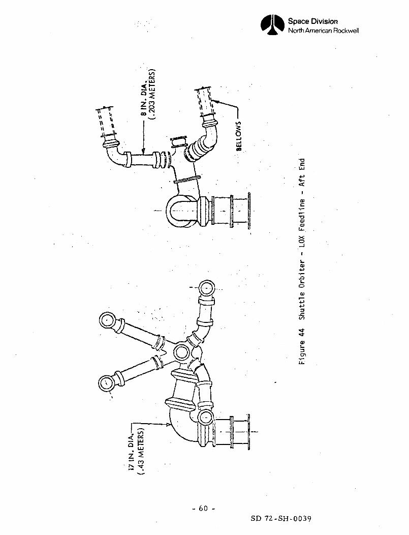
Space DivisionNorth American Rockwell
0)
•aa>a>
xo
0>-t-»
.0o0)
-p3
0)J-
- 60 -SD 72-SH-0039
Space DivisionNorth American Rockwell
11
"" 1V .— —
:r .
UJ '
<0
•
^
1
g=O
UJ
COce£
2=
COUo—
CO
E2=CO
i
of— 4
X
LfN
' . -
00
s
i
1
CD
s"1— 1
r -ro o•••J ^m^• • ^ "
r = >< r - x
3 s."~^ ^ •co oo f*— r^- i -i-H r— 4 1—4 r-4 r— 1 OO
g ^
i IID Z3 LU LU LU LU__J _l h— H- 1— 1—< <t CO CO CO CO
• CNJ fvj O» OO <±3
^ r-j ^j C\T r-j r_j
LT\ O O O CM LfNOO v^ \Q o** v^ f^»
—
oo
i \+^^^^ <D
by CD£ °
O)c
•o0)0)
LU
So i«
Z2 *cr
^0 ^
O
CO O QU- O
- 61 -SD 72-SH-0039
Space DivisionNorth American Rockwell
re4->fOQ
encQ.
COO
<D
.dro
-2S
Ozo_
^Q
&°
LU
coCOLUe
^^LU
1LL.
LU— co
T' CMLU 7co £;
-
-SLu
y^ _
1
tu•((*o
LU
oo
^
ZO1—o_e2coLUO
ZO»—
_l
**o -
CO CO
0 0^~ ^X XCM IX0 0• CO
COO CO•— o
cJ "*CN CN
IX CM
2? CM0 CO
•* ~O O
§ I8 8
LO —
coCO
0LU
i §•<; LUp£ eo
^ ^^LU O
< CO
<x tCO
"* CN
CO CO1 1o o•"" ~X X.
O LOCO *
*""
CO CO0 0
X. X
CN —CM "~
CM S>CO "<>
N- tc>> c
§ §
— «o
»—ULU
o zz z^ o60 uO COo ~o o
U Q
£ 2 «» >o -^ <i fe = "
*
CO CO CO CO CO1 1 1 1 1o o o o o•— r— • r— r— r—X X X X XCM . CM CN LO CO
^7 ^^ • • •• • ^o ^s, CN
^ 2 ^ 0 %X X * x XON O "> |X «rf-
CM CM ^ CO .
— CO
CN CN «O O COTfr Tf • LO
— CN
O O CM CM CM
CO CO- O O OO O CN CM CM
>o *o *or— ^ If) *Q *~• a ' • « •
Q _
i i o > i^. ^ Ll_ LULU LU _ < eneo co 2 >O O S as OO O 5 O- O.
LU U. O X _
oO
oLUZeo
Ou
coLU
ozo_
LU
X
- 62 - SD 72-SH-0039
y
o(1)
-aa>a>
CM0)
-Qro
o | -"•I
sl
'1
58
_iLU
£to
_4LULU
to
|
_l
<
PIP
E
MA
TE
RIA
L
2
o
XCOo
•cstoLUXUZCO
?
0
XCO
•
3,toUJXuZIX
?1o
XIXLf>
•
toLUXu
CO
a:UJ
LU
Q
CO
oX
CNO
•f~m
tuXU
i
fCO
oX
b•
toLUXU
8
?CO
o
X
o•
toLUXu
i
PIP
E T
HIC
KN
ES
S
(t)
2.2
SL
UG
S/F
T3
(l.l
3x
1tf
n A
A
CO
Ovr
COo
XCO
•
CO
<too3toCN
o
CN
m"
3.oCO0
XCO
• •
COiootoCN
0
CN
LOX
MA
SS
DE
NS
ITY
(P
)
MCMCO
sS
aSLL.
O
•sCM
ai&iaaSLL.O
*
1570
FT
/SE
C
(478M
/5E
C)
AC
OU
ST
IC S
PE
ED
(a)
|«lfCOCO
•
C2.5s *.LL. —CX X
» .2
5<CO' 0
i°*
LU <O^o o
C" XtX IT)
CO CM
3is•
LU -O4/^ 0
t ";CM IX
• •M3 —
ST
EA
DY
ST
AT
E F
LUID
VE
L.
(UQ)
RE
YN
OLD
S N
O.
(NR)
I opace uivisiorNorth American F
•aS
OO CN
8 iQ
a<CO ^>
8 -• •
a<
CO """8 0 0
o
DA
RC
Y W
EIS
BA
CH
CO
NS
TA
NT
(0
DA
MP
ING
CO
EF
FIC
IEN
T C
- 63 - 72-:
Space DivisionNorth American Rockwell
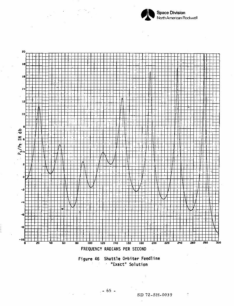
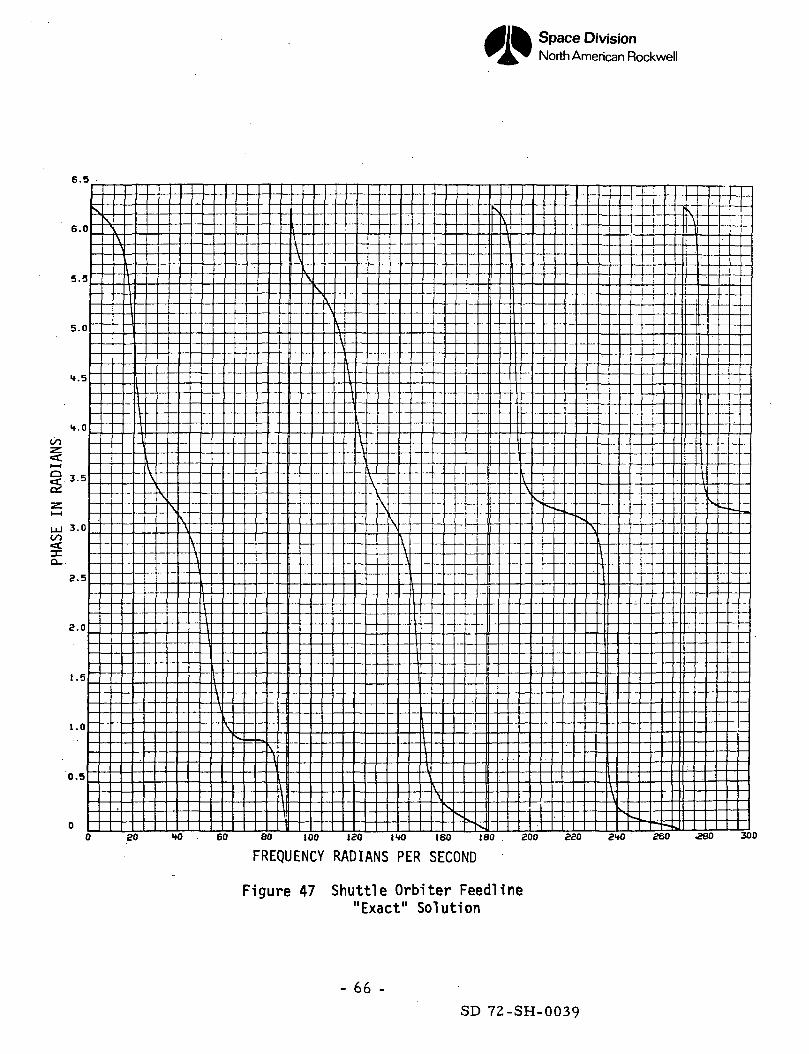
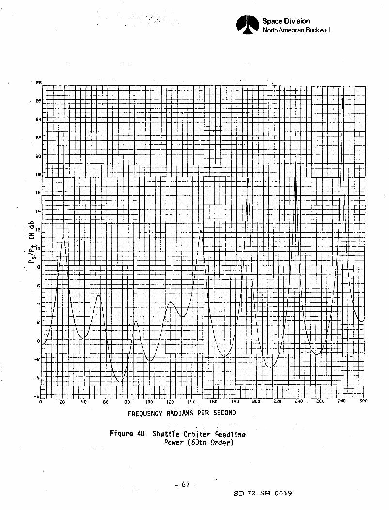
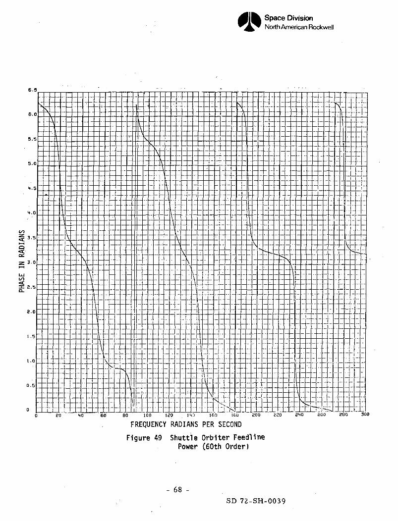
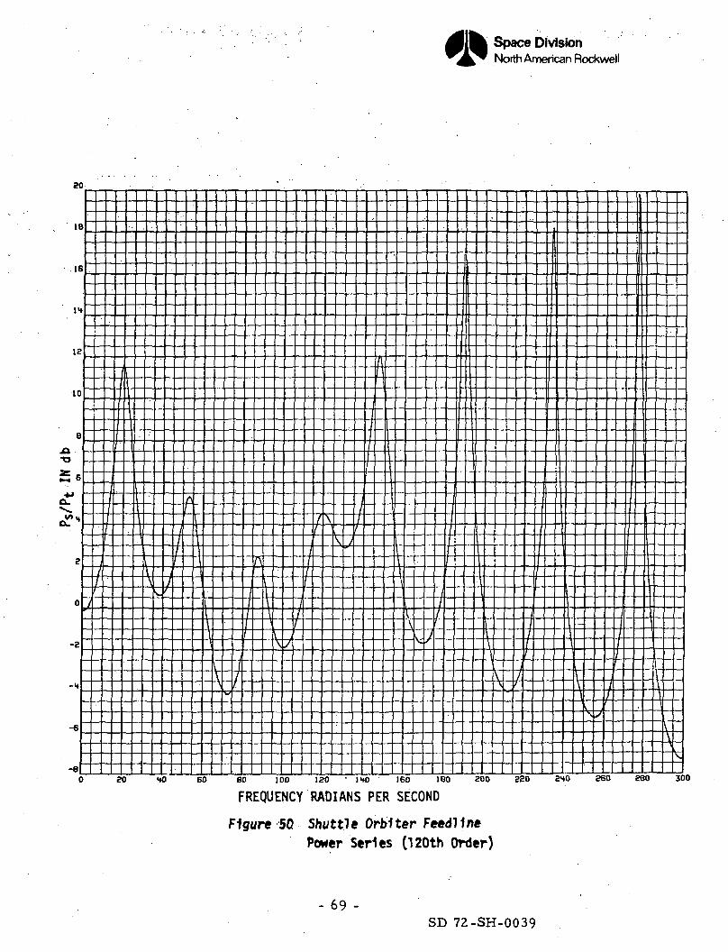
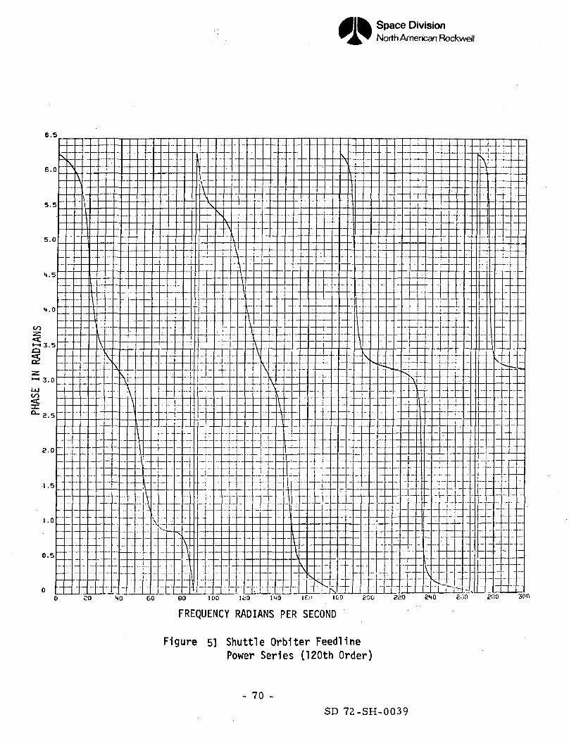
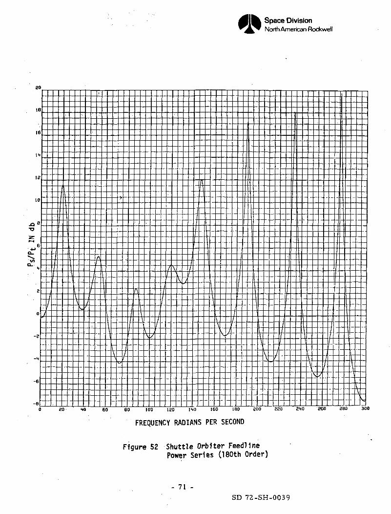
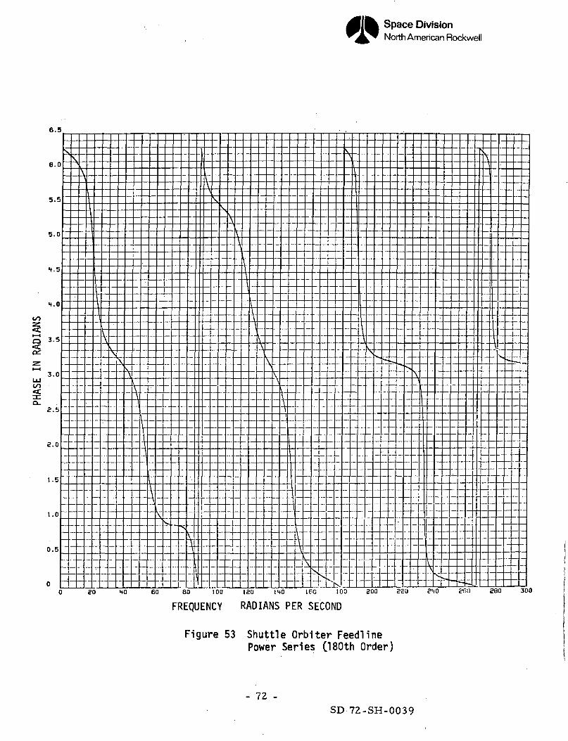
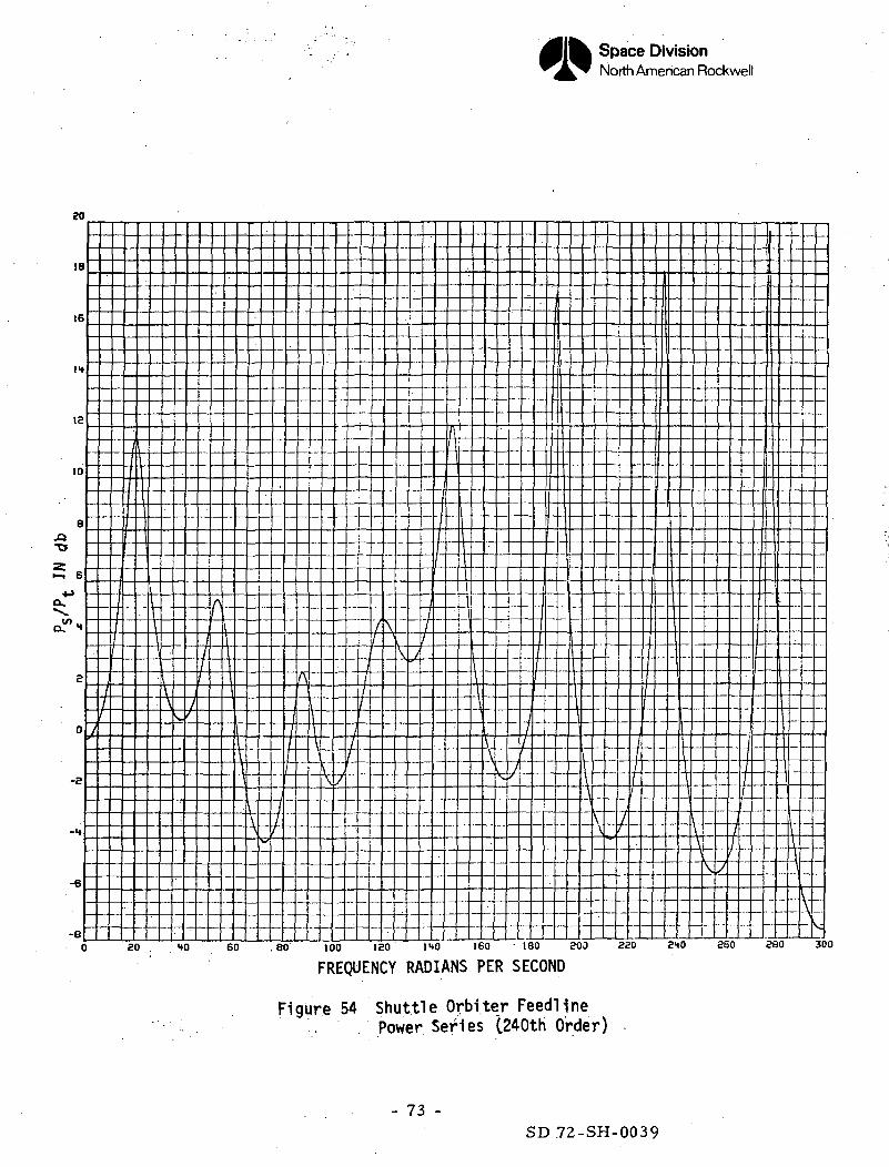
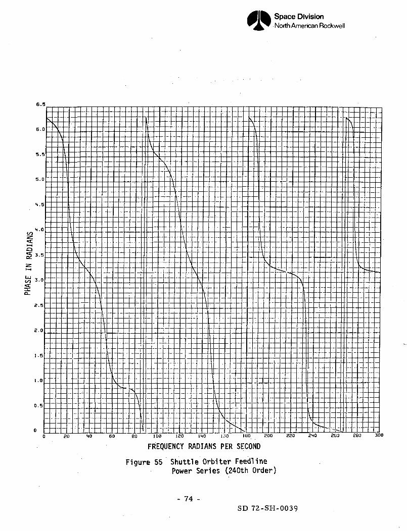
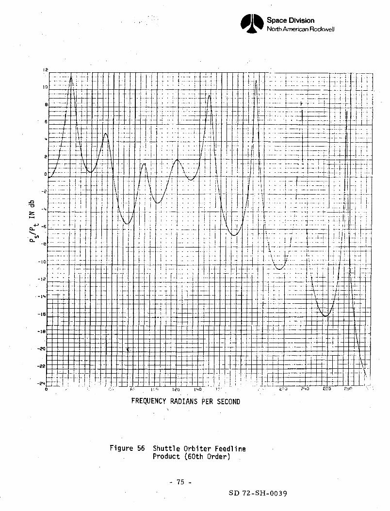
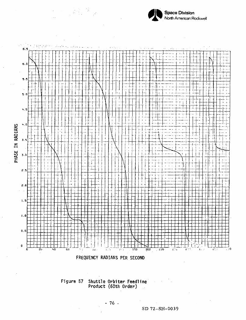
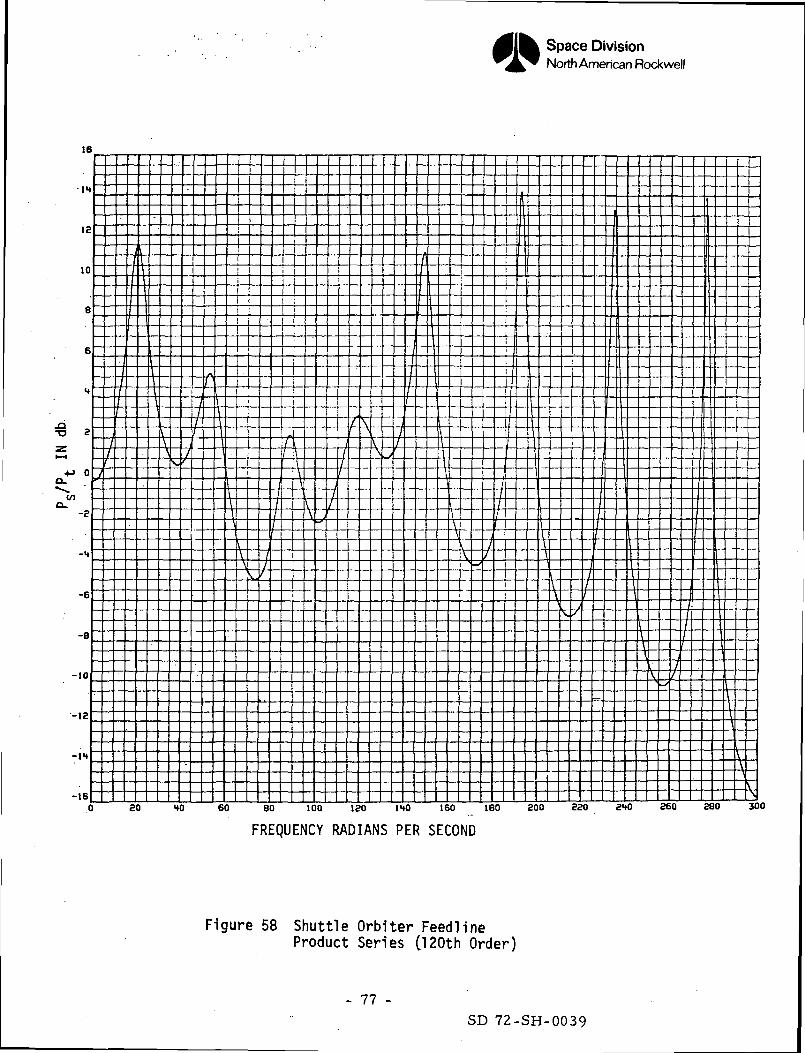
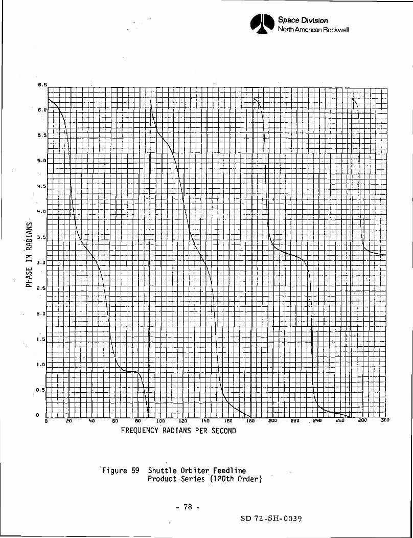
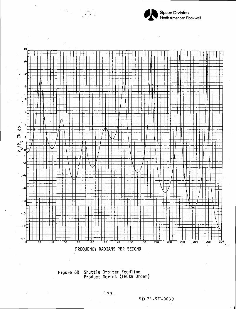
2. Numerical Results
Bode plots of the feedline transfer function have been obtained using the
"exact" transcendental functions for the transmission parameters. The results
are given in Figures U6 and Vf. This has been used as a basis for comparing
the numerical results when using the power and product series expansions.
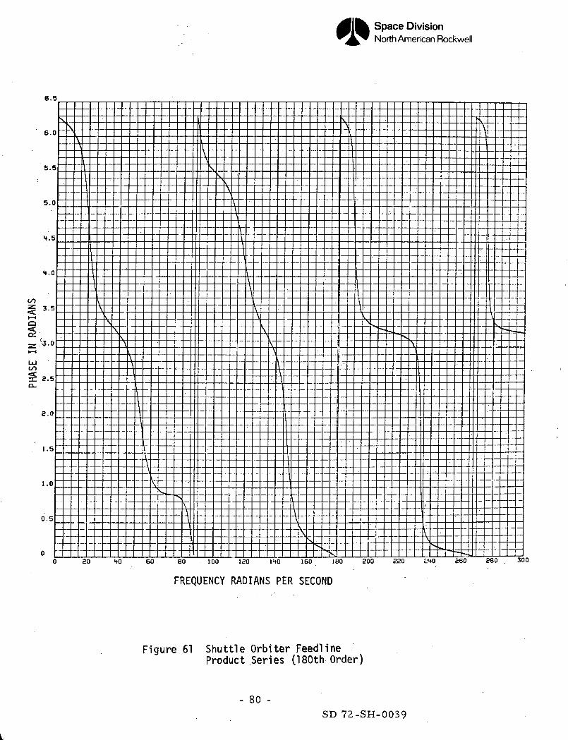
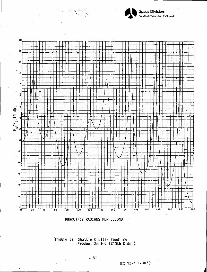
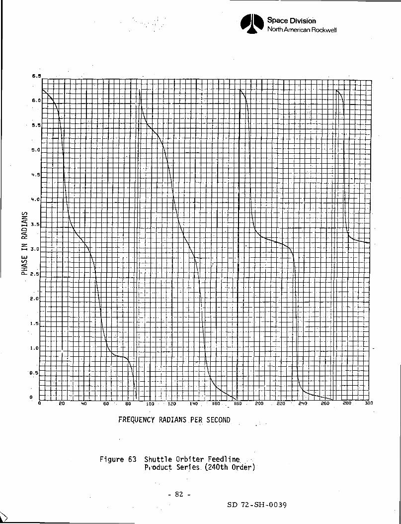
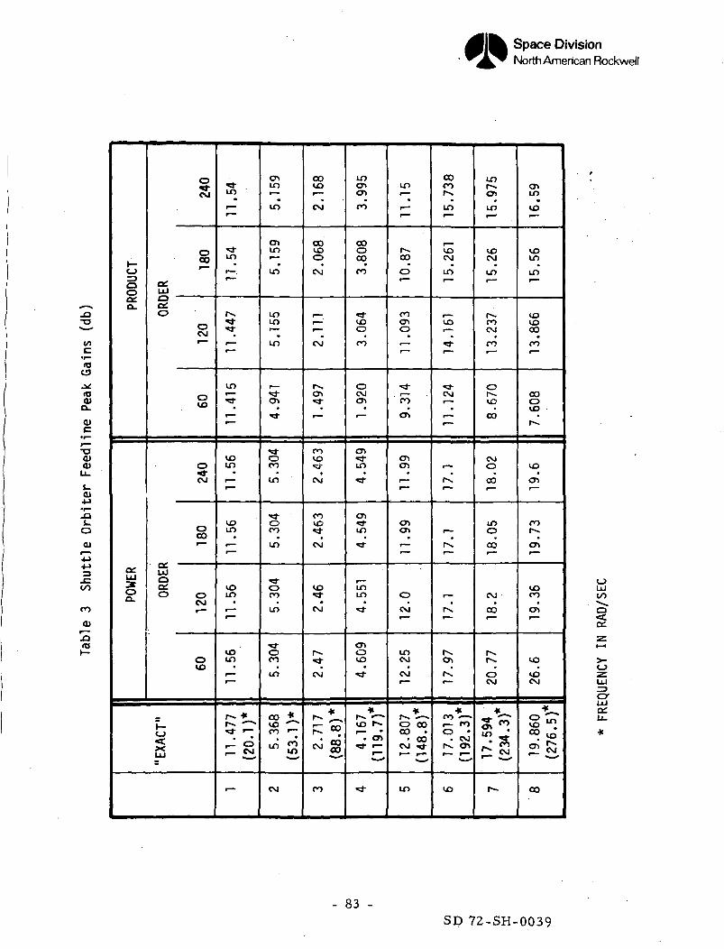
Results have been obtained for 60th, 120th, l80th, and 2UOth order expressions
for the orbiter feedline and are given in Figures 1*8 through 63. A
comparison chart showing the peak gains for each of these approximations is
shown in Table 3.
The NR stability program will allow the use of 60th order approximation to
the line. The higher order results show the improvement to be expected as
the order is increased. For the Shuttle Orbiter configuration, it is clear
that the power series representation is preferable to the product series
approximation for the transmission parameters. This is due in part to having
to subdivide the line for the inclusion of lumped damping due to bends and
changes in the cross-section of the line.
- 64 -SD 72-SH-0039
Space DivisionNorth American Rockwell
-1020 HO 60 BO 100 120 140 160 160 800 SSO 3HO 260 280 300
FREQUENCY RADIANS PER SECOND .
Figure 46 Shuttle Orbiter Feedline"Exact" Solution
- 65 -SD 72-SH-0039
Space DivisionNorth American Rockwell
6.3
6.0
20 HO . 60 80 100 ISO 140 160 ISO 200 320 3tO £60 £60 300
FREQUENCY RADIANS PER SECOND
Figure 47 Shuttle Orbiter FeedHne"Exact" Solution
- 66 -SD 72-SH-0039
Space DivisionNorth American Rockwell
300
FREQUENCY RADIANS PER SECOND
Figure 40 Shuttle Orbiter FeedlinePower (60th Order)
- 67 -SD 72-SH-0039
Space DivisionNorth American Rockwell
6.5
oo
aa:
LU
6.0
5.5
5.0
4.5
4.0
3.0
2.5
2.0
1 .5
t . O
0.5
0
\
—
\V
1
\i'\\
—• —
—
H
-—
—
s
-
--
-
-
-
\
-
-
_
-
—
\A
-
-
-
-
V-
_l
-
-
-
-
-
-
-
\
_
-
-
-
-
-
-
^
-
-•
-
-
-
I
\
-
-
-
--
-
-
-
--
-
--
— -
\
i
—
-
—
—
v,
-
—
-
s
-
-
-
—
--_._
y
\,\T
"1"
1
.....
--
---
....
--7
\\
AJ\\
...—
—
"""1
—
-
-
V\
-
-
-
•-
...
—
V
^v~
\
_
',:I
Ji1
I\
- -• •-
-
-
-\0 £0 40 60 80 100 120 1M;I IB
FREQUENCY RADIANS PER
-
-
--
\ -
-
.._
I
—
••b_L
\40
<
—
<•11
5E
-
-
-
—
- -
-
7.
...1
c
-
_.
-
-
-
-
s.
Ib
o^
X.
\
--
—
-L
—
_._
_. .
—-- —
..._
-
-
--
•5...- - •
--
::
~~-s
._..
V.>
•V-\
--
—
—
—
--
—
—
k
-
-
—
-•
_
>
iii
—
-
-
.._
-
-
-
-^
-
...
---
- •
--
-.-.-U £00 'dZQ 240 croO
ID
~ " IS
— ..
—
—
. _. ..
- -
:.:
.. _
\
\r
_ . ._
—
--
_ _
--
-
—
-
-
-
ri
-
—
-
-
-
-
880 30C
Figure 49 Shuttle Orfcxiter FeedHnePower (60th Order)
- 68 -SD 72-SH-0039
Space DivisionNorth American Rockwell
800 220 210 260 260 300
FREQUENCY RADIANS PER SECOND
Figure 50 Shuttle Orb'Uer FeedTlnePower Series (120th Order)
- 69 -SD 72-SH-0039
Space DivisionNorth American Rockwell
6.5
6.0
'iO lf.ii 1BO £00 £?.0 810 £50 230 3PO
FREQUENCY RADIANS PER SECOND
Figure 5] Shuttle Orbiter FeedlinePower Series (120th Order)
- 70 -SD 72-SH-0039
Space DivisionNorth American Rockwell
-e80 HO 60 80 100 120 1HO 160 180 £00 £50 840 £60 880 300
FREQUENCY RADIANS PER SECOND
Figure 52 Shuttle Orbiter FeedHnePower Series (180th Order)
- 71 -SD 72-SH-0039
Space DivisionNorth American Rockwell
6.5
6.0
HO 60 80 100 180 140 IPO 100 800 820 840 8S!> 880 300
FREQUENCY RADIANS PER SECOND
Figure 53 Shuttle Orbiter FeedlinePower Series 080th Order)
- 12 -SD 72-SH-0039
Space DivisionNorth American Rockwell
-8MO 60 8 100 ISO 1HO 160 180 S03 Z20 3HO 250 SBO 300
FREQUENCY RADIANS PER SECOND
Figure 54 Shuttle Orbiter Feedllne' . . ' . ' Power Series C240th Order)
- 73 -SD.72-SH-0039
Space DivisionNorth American Rockwell
6.5
6.0
SO HO 60 60 100 ISO 140 "150 I BO £00 280 240 2GO 280 300
FREQUENCY RADIANS PER SECOND
Figure 55 Shuttle Orbiter FeedlinePower Series (240th Order)
- 74 -SD 72-SH-0039
Space DivisionNorth American Rockwell
FREQUENCY RADIANS PER SECOND
Figure 56 Shuttle Orbiter FeedlineProduct (60th Order)
- 75 -
SD 72-SH-0039
Space DivisionNorth American Rockwell
to
^I—io
CO
3:Q-
FREQUENCY RADIANS PER SECOND
Figure 57 Shuttle Orbiter FeedlineProduct (60th Order)
- 76 -SD 72-SH-0039
Space DivisionNorth American Rockwell
-16HO 60 BO 100 120 ItO 160 160 200 220 2HO 260 280 300
FREQUENCY RADIANS PER SECOND
Figure 58 Shuttle Orbiter FeedlineProduct Series (120th Order)
- 77 -
SD 72-SH-0039
Space DivisionNorth American Rockwell
6.5
6.0
5.5
5.0
.H.5
1.0
00
C£
<c.Q.
3.5
3.0
2.5
3.0
1.5
1.0
0.5
SO HO 60 80 100 ISO 140 160 180 800 SZO ZtO 860 280 300
FREQUENCY RADIANS PER SECOND
Figure 59 Shuttle Orbiter FeedlineProduct Series (120th Order)
- 78 -SD 72-SH-0039
Space DivisionNorth American Rockwell
-IHSO HO 60 80 100 ISO 140 160 180 800 320 2HO 2GO 280 300
FREQUENCY RADIANS PER SECOND
Figure 60 Shuttle Orbiter FeedlineProduct Series 080th Order)
- 79 -SD 72-SH-0039
Space DivisionNorth American Rockwell
6.5
6.0
5.5
5.0
4.5
4.0
oo•z.«C>—i
C£
3.5
'-3.0
oo<c
2.5
S.O
1.5
1.0
0.5
SO 40 60 80 100 120 140 160 160 200 820 L'40 £60 280 . 300
FREQUENCY RADIANS PER SECOND
Figure 61 Shuttle Orbiter FeedlineProduct Series (180th Order)
- 80 -
SD 72-SH-0039
Space DivisionNorth American Rockwell
-is£0 HO 60 80 100 120 1 0 160 ISO £00 320 ^1«0 260 880 300
FREQUENCY RADIANS PER SECOND
Figure 62 Shuttle Orbiter FeedlineProduct Series (240th Order)
- 81 -SD 72-SH-0039
Space DivisionNorth American Rockwell
6.5
SO tO 60 80 100 120 IHO 160 180 800 820 8tO 860 . 880 300
FREQUENCY RADIANS PER SECOND
Figure 63 Shuttle OrbHer FeedlineProduct Series (240th Order)
- 82 -SD 72-SH-0039
Space DivisionNorth American Rockwell
-O-o
(U
0)o_0)
•o0)(U
0>
.0,oOl
oo
coO)
<_>ooo.
a:LU
oo.
^CM
§^
OSUJ
a:o
0CM
OVO
O
CM
O00"
UJoat.0 0
CM
OVO
l_oXUJ
J"in
ini—.r"-
rx5
-
in
*r—
voin
-
vo
r~
VOin
-
voin•t— •"~
f*** ""
r-I O
-
enin•—in
enin
in
ininr—in
en
**
oCO
in
oCO
in
oCO
in
oco•in
co *VO "co •—
•
in <*>in
CM
COVO
CM
COvooCM
r—
CM
^5
"
COVO•vf
tCM
covo
CM
vo
CM
^•OJ
r_ * ZT"
CM °0vNl eg
CO
inen01CO
CO000
CO
>vooCO
oC\Jen
enin
"*
in
**"
U")Lf>
^
0vo•
*4"
D ^^^ *
*
in•—
J
ooo'
CO
o
-
^'*?
enen
-
en
-
oCM
inCM•CM
"
*_
0 00CO •• 00
CM J-
m
00COrm
voCM
in1
,_VO
^
CM
~
i —
£l
,__
J
-"
O•
r
""*
CO *~*i— COo •• CM
^ cn
vo
tnenin
voCM
inr—
fv.COCM
n
ovo
CO
CMO
00
inooo
CM
CO
fs•oCM
*
?fi ^
H-
eninvo
voinin•""
VOVOooCO
ooovO
VO
en
co
en
VOCO
"
VO•
VOCM
*_
vo ^*iCO
UJoo
o
crUJ
- 83 -SD 72-SH-0039

Page Intentionally Left Blank
Space DivisionNorth American Rockwell
V. EIGENVALUES AND THE SOLUTION VECTOR
The stability equations have "been reduced to a system of linear homogeneous
equations with constant coefficients. They are represented "by the following
equation:
i c o) "M r owhere y represents a vector whose components are the dependent variables
appearing in the stability equation and is a matrix whose elements <
\tare polynomials in the differential operator D. Letting ^J ~ ~E Q.
we obtain -. c / \ \ „J-CA) '-M - O
For a non-trivial solution, it is required that | j(A) = 0. The order of the
characteristic equation 5C )| = 0 determines the number of arbitrary
constants in the solution.
The eigenvalues A^ of the characteristic equation are obtained using a program
currently available at NR and has successfully been used for POGO stability
studies. The analysis need only consider the case in which all the eigenvalues
are distinct. The system of equations J(O)M.= 0 can be reduced to a system of
linear differential equations with constant coefficients such as - = Axclt,
such that one could then obtain the eigenvectors associated with the matrix A.
For the purpose of the present problem, it is more meaningful to obtain the
solution vector y for each of the characteristic values X« obtained from
the solution of the characteristic equation. Letting F(XK) be the adjoint of
) we then have: (Ref. U) .
- 85 -SD 72-SH-0039
Space DivisionNorth American Rockwell
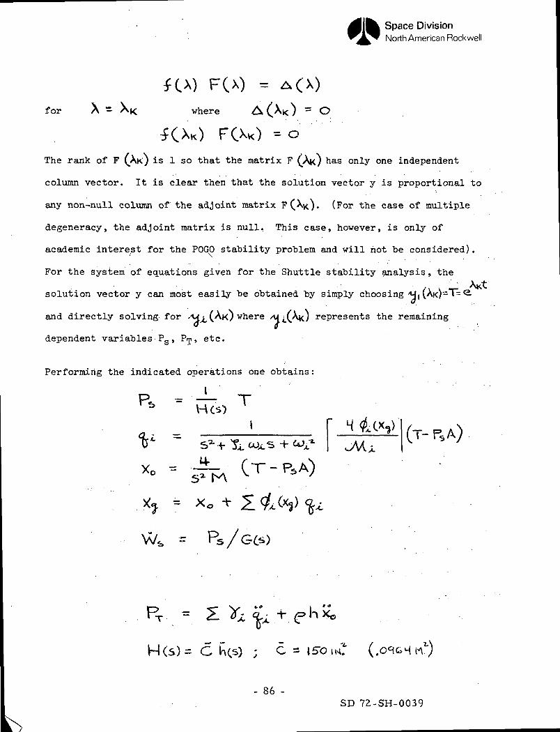
F(x) = A(X)
for X - XK where A(^Xi<) - C
KXO FOO = O
The rank of F (An) is 1 so that the matrix F ( AK) has only one independent
column vector. It is clear then that the solution vector y is proportional to
any non-null column of the adjoint matrix F(Aj<). (For the case of multiple
degeneracy, the adjoint matrix is null. This case, however, is only of
academic interest for the POGO stability problem and will hot be considered).
For the system of equations given for the Shuttle stability analysis, the
solution vector y can most easily be obtained by simply choosing /H,(Ai<)"1T=
and directly solving for •>u^(AK) where /\n(Ai<) represents the remaining
dependent variables PS , Prp, etc.
Performing the indicated operations one obtains:
>?(T-
-v
PT =
H(s)= C hcs) ; C = 15-0 iw*
- 86 -SD 72-SH-0039
Space DivisionNorth American Rockwell
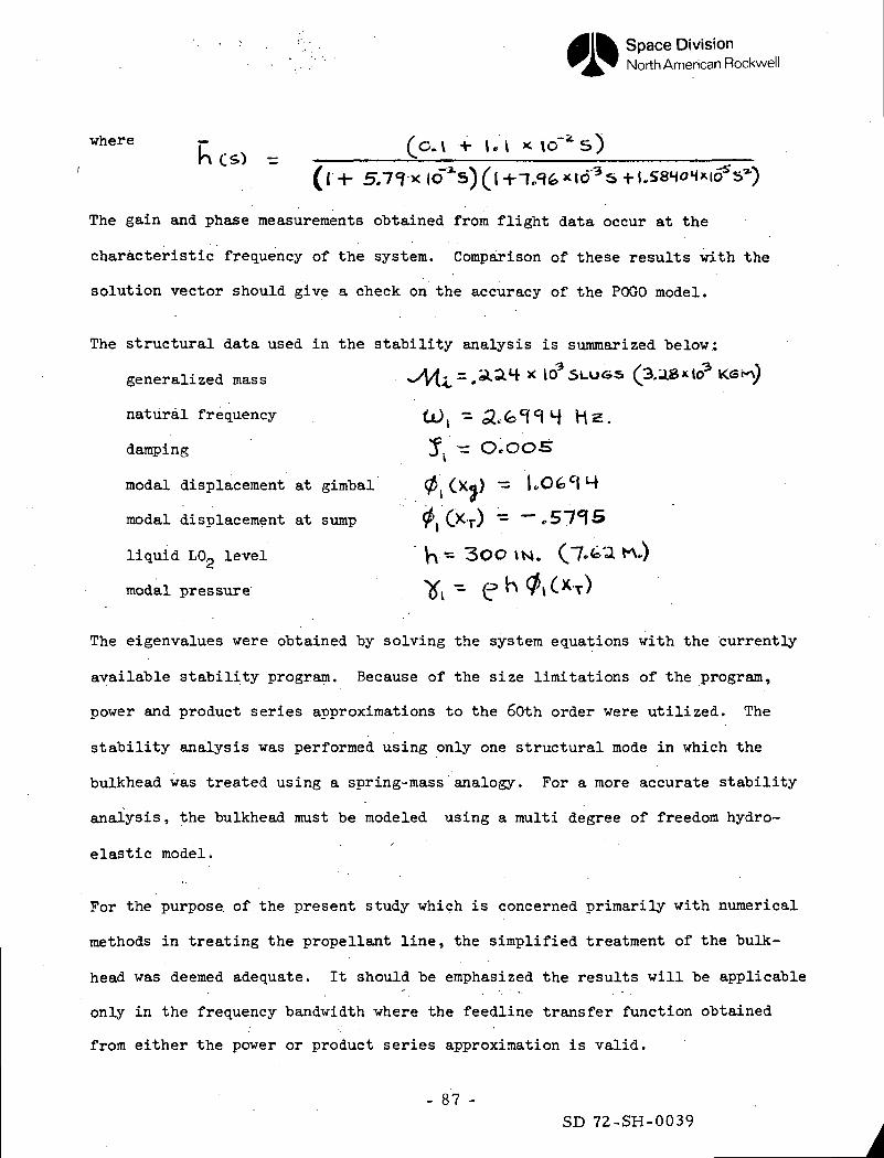
where —h C£> =
(l-i- 5/7<?xio~*s)(|-t--F.,q6xtd3s-H.f
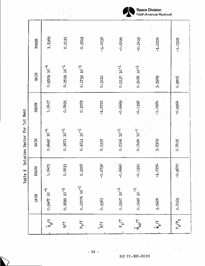
The gain and phase measurements obtained from flight data occur at the
characteristic frequency of the system. Comparison of these results with the
solution vector should give a check on the accuracy of the POGO model.
The structural data used in the stability analysis is summarized below;J3
generalized mass *>Vtj. = -aa4 * lO^St-UGS (3.a»*U
natural frequency it), S.fe'H
damping ^ ~ O.OO-5T
modal displacement at gimbal 0' 9
modal displacement at sump r i C T) ~
liquid L02 level \\ - 3OO \tt. (7'<*'a. K.)
modal pressure
The eigenvalues were obtained by solving the system equations with the currently
available stability program. Because of the size limitations of the program,
power and product series approximations to the 60th order were utilized. The
stability analysis was performed using only one structural mode in which the
bulkhead was treated using a spring-mass analogy. For a more accurate stability
analysis , the bulkhead must be modeled using a multi degree of freedom hydro-
elastic model.
For the purpose of the present study which is concerned primarily with numerical
methods in treating the propellant line, the simplified treatment of the bulk-
head was deemed adequate. It should be emphasized the results will be applicable
only in the frequency bandwidth where the feedline transfer function obtained
from either the power or product series approximation is valid.
- 87 -SD 72-SH-0039
Space DivisionNorth American Rockwell
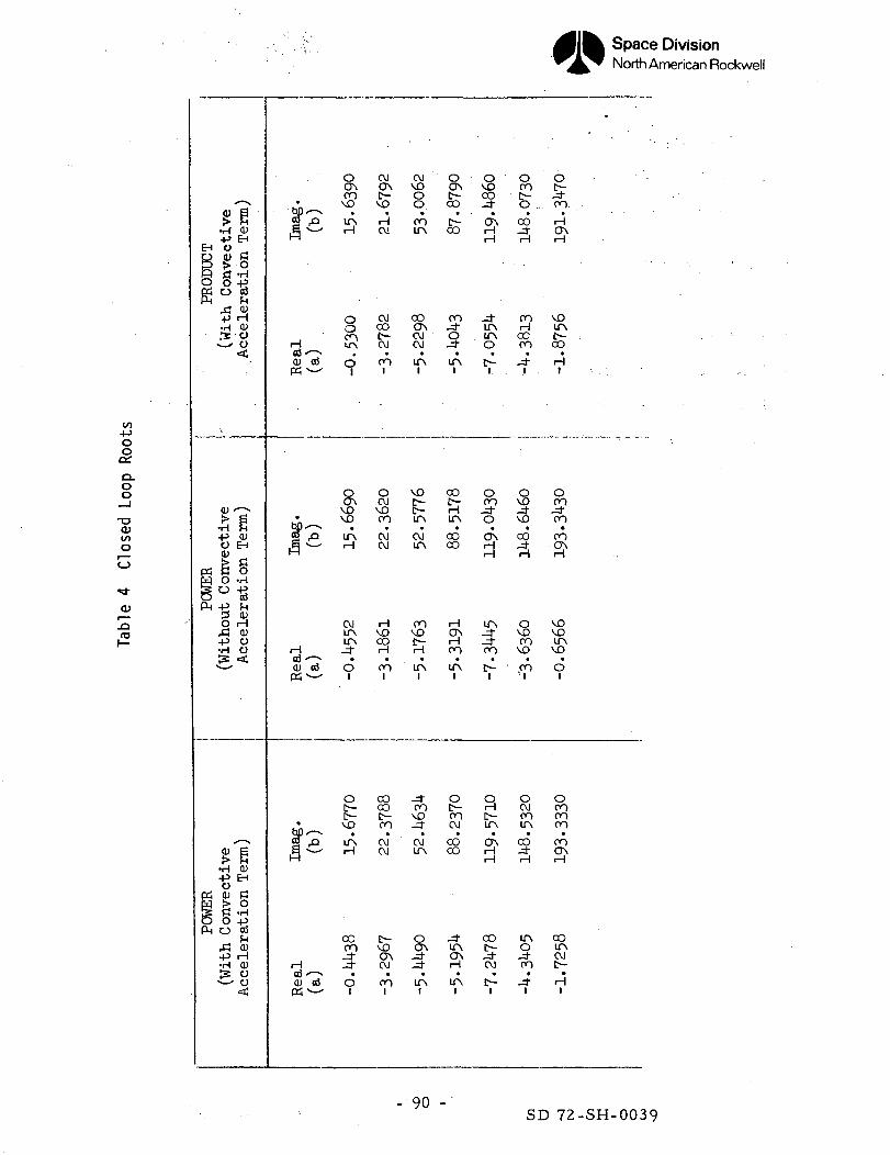
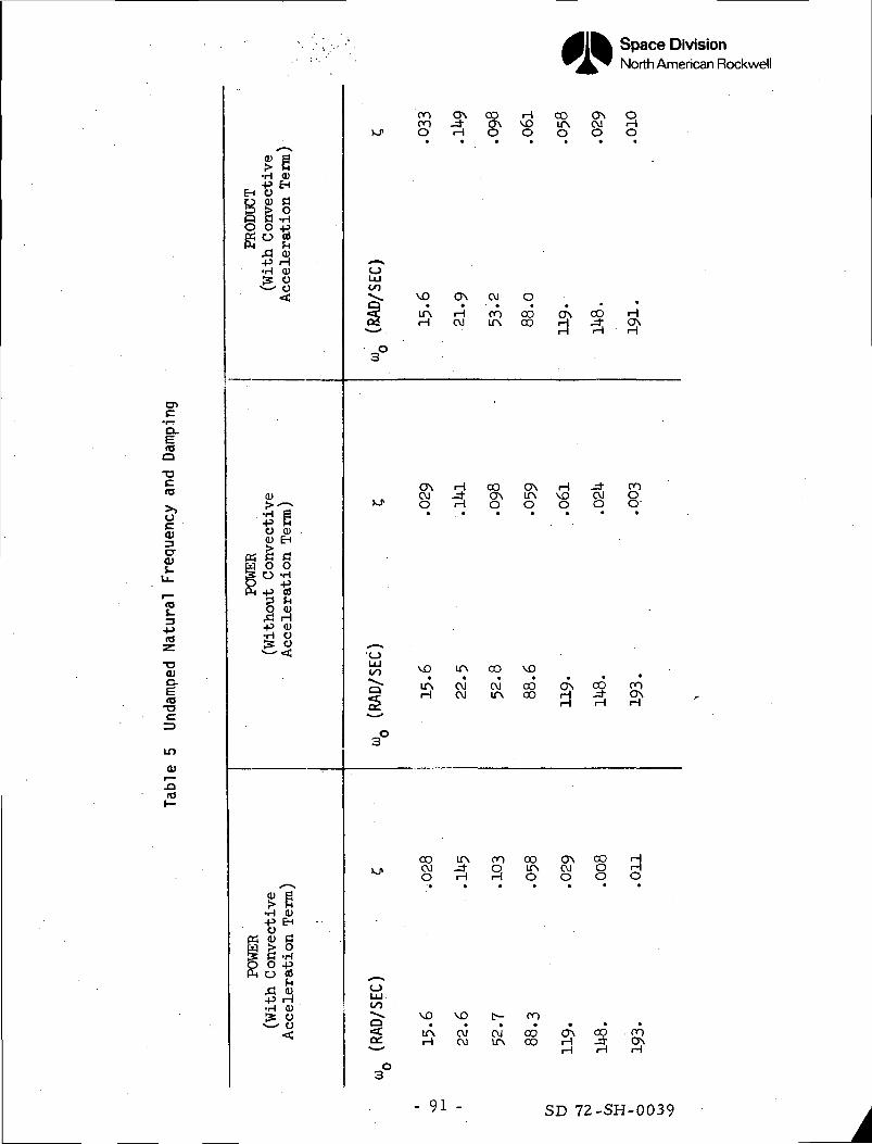
The closed loop roots and the associated solution vectors have been obtained
with and without the convective acceleration terms and are given in Tables h
and 6. The undamped natural frequency and the damping are given in Table 5.
The results indicate the convective acceleration terms were of minor importance.
Since only one structural mode was used it should be emphasized that only the
first root has significance. For this reason the solution vector has been
tabulated for only the first characteristic value.
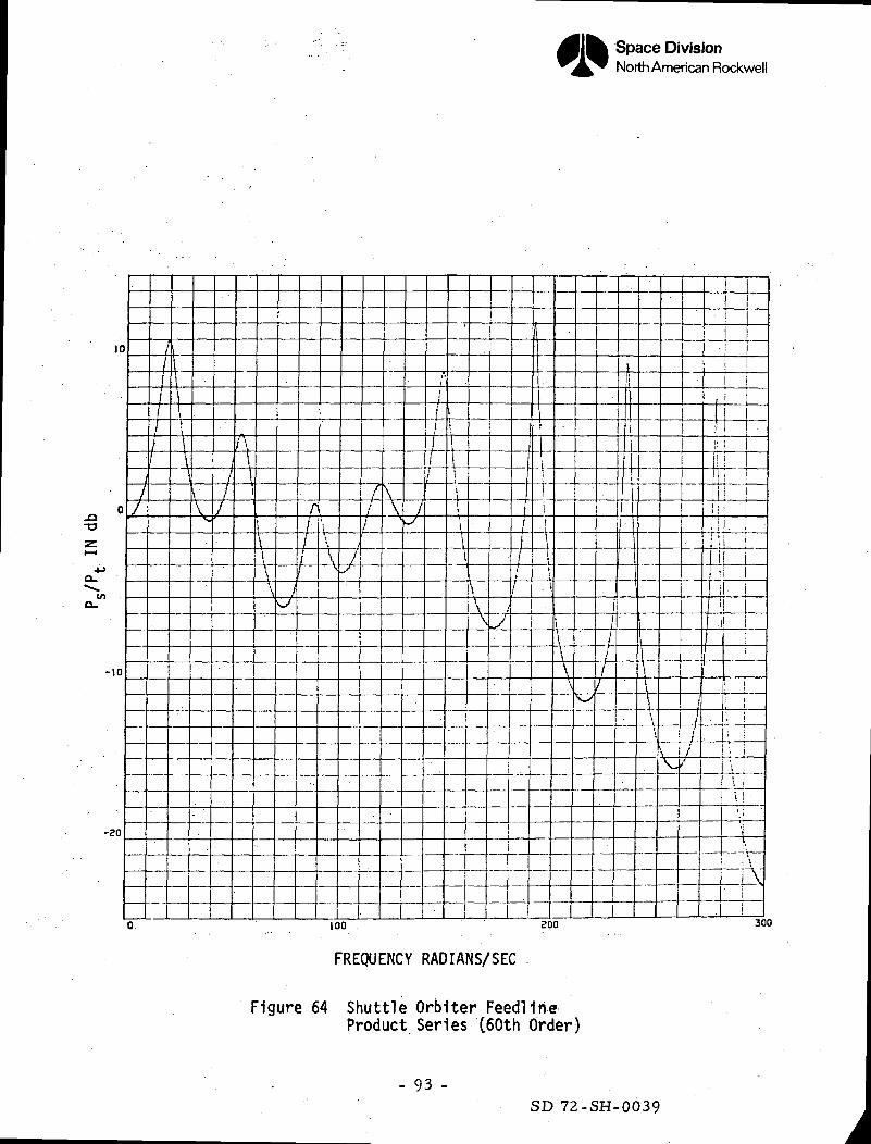
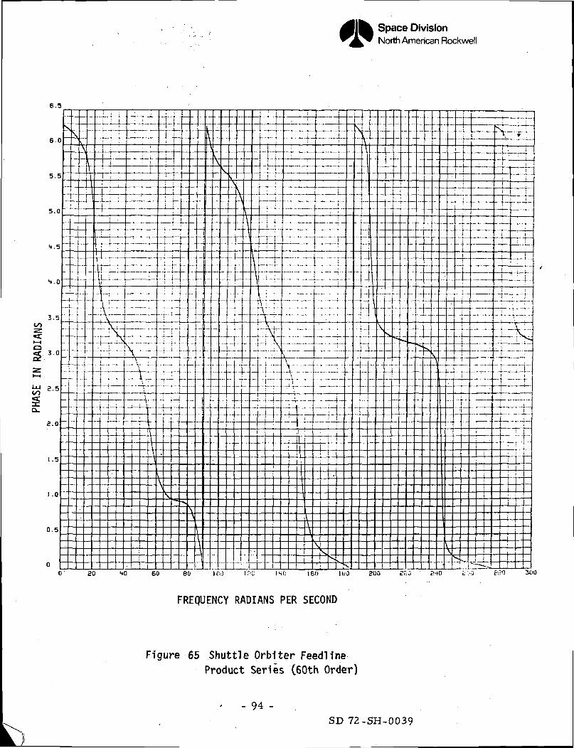
In order to perform the stability analysis using the product series expansion
for the transmission parameter it was necessary to alter the model from that
used to obtain the Bode plot shown in Figure 56 and 57. The damping due to the
bend at B (see Figure U5) was included with the entrance losses at A. This was
done to reduce the number of equations in order to make the feedline model
acceptable to the stability program. The order of the product series approxima-
tion, however, was kept at 6dth order. The effect of this model change can be
seen by comparing the original Bode plot (Figure 56) with the amended one with
the bend damping lumped at the entrance given in Figures 6k and 65.
The largest effect appears to occur at the first mode where the decrease in
gain has the effect of increasing the damping from 2.8 percent to 3.3 percent.
Although the remaining results are not too meaningful, since only one structural
mode was used in the analysis, the first five closed loop roots obtained from
the power and product series methods are in substantial agreement. In order
to get agreement in a higher frequency range, higher order approximations are
required.
The computer time required to obtain the closed loop roots was from 3-^ CPU
minutes when the feedline was modeled with either power or product series
- 88 -
SD 72-SH-0039
Space DivisionNorth American Rockwell
expansion. Bode plots of the feedline transfer function of the Shuttle Orbiter
configurations for each of the polynomial approximations utilized about 0.3
CPU minutes. The computations were performed/on an IBM Model 165 computer."'%•.
•)K
Nyquist diagrams were not presented because the numerical procedures used are
not meaningful beyond a given frequency. An instability at 100 Hz for example
would result in an instability in the Nyquist diagram. It should be again
emphasized that the stability results are only valid in the range where the
Bode plots of the approximate feedline transfer functions are in agreement
with the "exact" results.
- 89 -SD 72-SH-0039
Space DivisionNorth American Rockwell
to•uoo
CLOO
-oO)c/1o
o
O)
-QCO
EH
O
e
PSr-r"]
§(5PH
P^Hry-i
!l?or\ i
gl•H
O<U
rt0O
rt
•P•H3:
\
0}f>
•iH+3O<DJ*OO
-P
O^f"}
-P•H;s
(1)
.•H
-8OJ
coo
•P•H
S
^g
QJEH
ao•H-P03
0)H0)oo
rf^^S
g0)
EH
O•H•Pa)fn
H0)OO
s-g
a;EHflo•H-Pc3i0)
Hcuo
O OJON O"\co C-
S)'2' lA H^ H OJ
8 OJCO
CO C—H m OJ<1) cd o f
O OO\ OJ
VD VD• vo CO
f f> ^>^ ^\j— H OJ
OJ HLfN VOir\ co
P- I -j" pHaj '"^ • •0) o3 O CO
0 00C~ COt- c^
Mx-^ ^ °?CO jQ LP\ CVJB v — H OJ
OO t-CO VO
H J" OJ
<u cd o co
OJVOooCO
OvOJOJ
ITN
VOC-
ITN
OJtr\
COvof~i
*Lf*\
COvoJ-OJLTN
O
5>-j/ITN
0
0§
^1OO
CO
iLf\
CO
f— I
ITN
OOCO
Ho*\HCO
Lf\
O
COOJ
CO00
J-LfN
H
IT\1
vOs•
o^rHH
J-ITN1TNO
^
OOO-4-ocr\HH
ITSJ--d-CO
t^-1
oHc-tr\O\i — |H
00
OJ
[V_1
oco
• & . .001 — 1
S1COco
f
o-=rVO
00
"3
oVOCOVO
CO1 1
oOJCO
COJ-H
Lf\oooJ-
o
CO
H
1 — 1
voITSc-OO
H1
oOO-d/CO
COcr\H
VOvoLTN
VO
o
oCOCOcoCO
I — 1
CO
OJt—H
1
- '90 -SD 72-SH-0039
Space DivisionNorth American Rockwell
too•acas
<u3cr<us-
-oO)C-
<o
0)
• H O )•P EH
EH 0 ^
O O +5
S3•H 0)!3 O— o
0)
O Q)<U EH
W O OS O -Hp -pft -p o3
IS-P 0)•H O^ 0
•H 0)
•8* 'P5 CU CH
io-Sft <D•P H•H 0
~J
OO ON OO H OO ON OOO _* O\ V£) IP, CM r-\
U > O H O O O O O
OUJoo-^ VO ON CVJ O
« C I f N r H o O O O O N O O HC O H C M i r \ O O r - j - d - O N• rn rH rH
3°
ON H oo ON H -d- ooCM _* ON Lf\ VO CM O
>-J" O H O O O O O '
{Jj VQ ITv CO VO
^ - I T N C M ( M O O C T \ O O O Or f H C v l l T N O O r - j - d - O N22 H H H
3°
oo ir\ oo oo ON oo HL I > c v i j - o i r N C v i o H
O H H O O O O
0LUoo^- VO VO t— OO
« < l A c M C M O O O N C O O Oo c H O J t r \ o o H J ; O N^•^ rH i — 1 rH
3°
- 91 - SD 72-SH-0039
Space DivisionNorth American Rockwell
1FM
H
H
<gK
5^JCJ
pr"]
CO
K
^M
ONVOroIfN•
H
l
3
IfNON•
O
£f
ITN
H
.4-l
3
CMONJ-ON
d
LTNCMJ-ITN
H
1OH
r-OO
ON
d
t-o
.X
1
H
3CO
d
H1
9ONroLTNCO
o
LfNON
VOCM
d
H
9H
vOCO
d
roCOvoCM
d
HiP-J
ONONvorod
^_
cr
J
GOrod
H
9ONCO
•
O
ITNCOCMCO
d
H1
9HHCOH
d
00oCMCO
d
H
oH
J-
CMCO
d
i—
D.
,
OOcoOJCM
H1
9CMCO
O
CMCMC-CM
H
tfNCOCOCO
d
CMONC-CM
H1
covoCOrod
,_
.><
1
oo
di
H
3
%ITNt
0
ONvOVOvo
d
H1
9vo1— \ir\
d
. CMvOVO
, VO
d
'
H|
q1-1
ir\d
i-
CL,
1
!d.i
H
9oo
O
VOONH*
di
Hl
9ON
-J"
H
d
HONroHd
Hi^^i— tITNON
d
1—
O'
•371
8CMCM
H1
ON00ONf^
CO
COVOCM
H
ONOCOITN
OO
IfN^~CM
H1
1ITN
CO
1—
• 3i"
i
iITNCMITNO•H
i
VOCMITNON
CM
i
ITNONON•
O
H-d"
CO
CM
O^»OOON
d
ON
CO
CM
Q^t/>
O-
i-o
s-ooO)
co
(£>
o»-Qto
fc.- 92 -
SD 72-SH-0039
Space DivisionNorth American Rockwell
too aoo 300
FREQUENCY RADIANS/SEC
Figure 64 Shuttle Orblter FeedHrieProduct Series C60th Order)
- 93 -SD 72-SH-0039
Space DivisionNorth American Rockwell
6.5
6.0
0 SO 40 60 60 IOJ I.'-C IHf; 160 IBO 200 £23 £'10
FREQUENCY RADIANS PER SECOND
Figure 65 Shuttle Orblter Feedllne-Product Series (60th Order)
- 94 -SD 72-SH-0039
Space DivisionNorth American Rockwell
VI. CONCLUSIONS AND RECOMMENDATIONS
The results of this: study show that the Shuttle Orbiter feedline may be modeled
adequately by using polynomial approximations .to .transcendental functions
appearing in the transmission parameters. The . adequacy of the approximations
may be determined by a comparison of the Bode plots of the feedline transfer
function obtained from either the power or product series approximations with
the "exact" solution obtained using the transcendental functions. For complex
feedline with multiple bends this study indicates the power series method is
to be preferred over the product series . This study has also shown that the
line damping may be adequately approximated by lumped damping provided the
elemental sections are made sufficiently small. When using the power series
method this is automatically accomplished by the requirement that the nondimen-
sional frequency ty A of the largest elemental section be less than one.
Procedures have been developed for including the effect of the convective
acceleration terms in the feedline representation. It has been shown that
the sole effect of this term is to cause a phase shift of - in the feedline<x a.
transfer function. For the Shuttle Orbiter configuration this is quite small
and may be neglected. This term, however, was included in the feedline transfer;
function and the stability analysis.
The Shuttle Orbiter line was modeled using polynomial approximation of up to
the 2UOth order. Using the NR stability program the closed loop roots were
obtained using a 6oth order polynomial approximation for the line.
- 95 -SD 72-SH-0039
Space Division .North American Rockwell
The system equations used for obtaining these results did not include the
hydrogen system and only one LOg bulkhead mode was used in the analysis. The
stability results therefore, as well as the solution vector, should only be
used for comparing the results of different numerical procedures.
The computer time required to obtain the closed loop roots was from 3-U CPU
minutes when the feedline was modeled with either power or product series expan-
sion. Bode plots of the feedline transfers function of the Shuttle Orbiter
configurations for each of the polynomial approximations utilized about 0.3
CPU minutes. . .
The procedures developed in this study for obtaining the approximate and the
"exact" Bode plots of the feedline transfer functions are completely general,
although they were used for a specific feedline geometry. These procedures should
be automated in a digital program so as to handle an arbitrary feedline with
branches, bends, pumps, etc., to obtain the required dynamic feedline character-
istics. The dynamic characteristics may then be obtained using a Taylor series
approximation for the elemental sections and the results checked with the "exact"
solution. Having modeled the feedline to the required degree of accuracy
necessary one can then proceed to determine the closed loop roots and the
associated solution vector by incorporating the feedline model into the system
equations. . . .
- 96 -
SD 72-SH-0039
Space DivisionNorth American Rockwell
VII. REFERENCES
1. Titchmarsh, E. C. The Theory of Functions. Oxford University Press (1939)
2. LeVine, Dickey Root Finding Techniques for a Transcendental Function.M.S. Thesis, Purdue"University (1968).
3. Jolley, L. B. W. Summation of Series, Dover Publications, Inc. New York.
U. Frazer, R. A., Duncan, W. J., Collar, A. R. Elementary Matrices,Cambridge at the University Press (i960).
- 97 -SD 72-SH-0039
Space DivisionNorth American Rockwell
APPENDIX A
DETERMINATION OF TRANSMISSION PARAMETERS
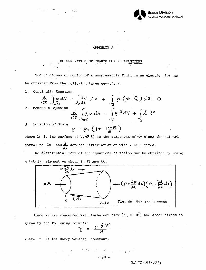
The equations of motion of a compressible fluid in an elastic pipe may
be obtained from the following three equations:
1. Continuity Equation
2. Momentum Equation
_fL I f»-i> cL\t
3. Equation of State
e 3-e-where 5 is the surface of V,-tr->v. is the component of -v- along the outward
normal to 5> and - denotes differentiation with V held fixed.2x
The differential form of the equations of motion may be obtained by using
a tubular element as shown in Figure 66.
x+'c(_x Fig. 66 Tubular Element
Since we are concerned with turbulent flow (N = lO^) the shear stress isK
given by the following formula: f . .z
••r = ec 8
where f is the Darcy Weisbach constant.
- 99 -SD 72-SH-0039
Space DivisionNorth American Rockwell
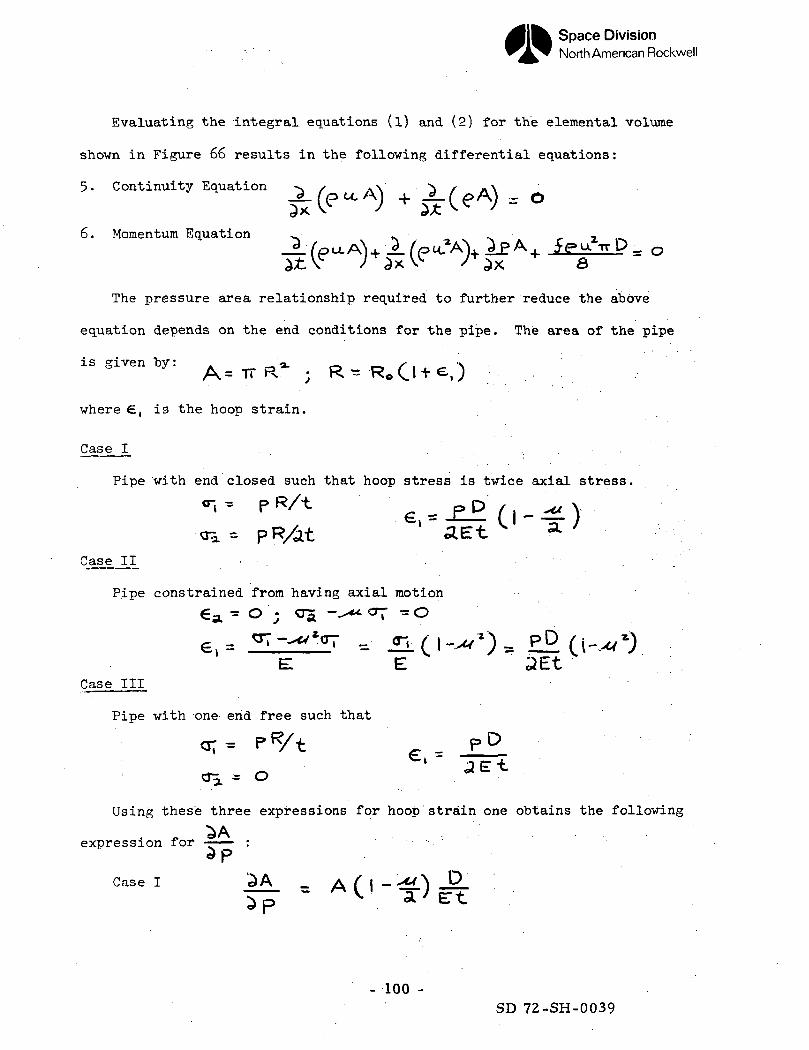
Evaluating the integral equations (l) and (2) for the elemental volume
shown in Figure 66 results in the following differential equations:
5- Continuity Equation -x
6. Momentum Equation .s 0
The pressure area relationship required to further reduce the above
equation depends on the end conditions for the pipe. The area of the pipe
is given by: ^ R<L _ ^^ | '
where £, is the hoop strain.
Case I _ . . ' • . . . , . . - . '
Pipe with end closed such that hoop stress is twice axial stress.
«i - P RA e _ PP / . -« v -•«*« PR/at ' '" ^ y
Case II - • . , .
Pipe constrained from having axial motion
-•^*t °T - O
2EtCase III
Pipe with one end free such that
< r a , o
Using these three expressions for hoop strain one obtains the following
„expression for
Case I ^A _ A ( I -''•&.)
- 100 -SD72-SH-0039
Space DivisionNorth American Rockwell
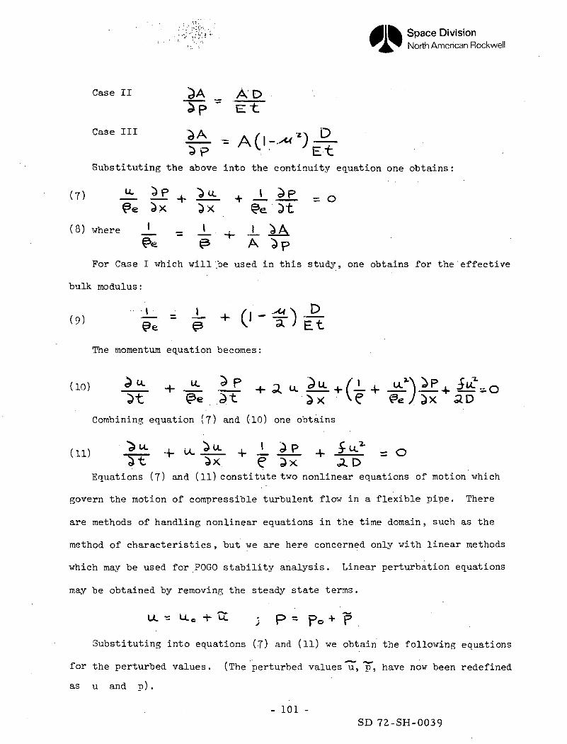
Case II ^A _ AD
^P " E-t
Case III ^A _ ./ VZA D
^P ^S ' ^Et
Substituting the above into the continuity equation one obtains
(8) where J_ _ J_ . J_&* ~ O A
For Case I which will be used in this study, one obtains for the effective
bulk modulus :
The momentum equation becomes:
do) AiL + Ji. If + q .1 3* +f ' +
Combining equation (?) and (10) one obtains
(ID ' *£ ^u.^L^'AL 4.1 : =0^t ^x. e 3x ^DEquations (7) and (ll) constitute two nonlinear equations of motion which
govern the motion of compressible turbulent flow in a flexible pipe. There
are methods of handling nonlinear equations in the time domain, such as the
method of characteristics, but we are here concerned only with linear methods
which may be used for POGO stability analysis. Linear perturbation equations
may be obtained by removing the steady state terms .
LL^UO+S: ; p = p 0 + p
Substituting into equations (7) and (ll) we obtain the following equations
for the perturbed values. (The perturbed values 'u", "p", have now been redefined
as u and p) .
- 101 -SD 72-SH-0039
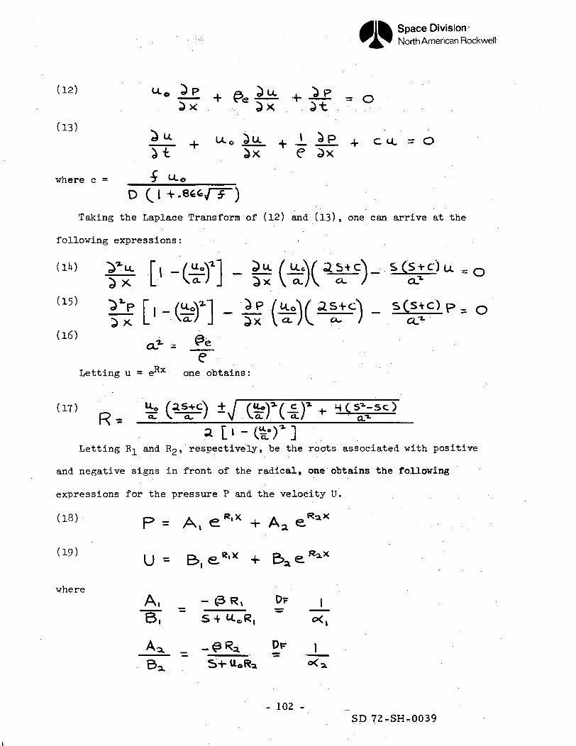
Space Division-North American Rockwell
+ .. + = 05X ^X 3t
(13) . . . .* u 4. ix0 Su + J...LP 4 cu. = a
e
where c = J
DOTaking the Laplace Transform of (12) and (13), one can arrive at the
following expressions: ;
— - ' f \. s \. . .*• v
U. =-/u°?l ^u. /UcV as+c'N sCsvc')^~' J ."" ^ V^A ~^~) ce
-z. °
(16) &e
Letting u = e^x one obtains:
Letting R^ and R2, respectively, be the roots associated with positive
and negative signs in front of the radical, one obtains the following
expressions for the pressure P and the velocity U.
p = Av e*'x + Aa-.«
where
B, S4W-0R,
Dr
- 102 -SD 72-SHr0039
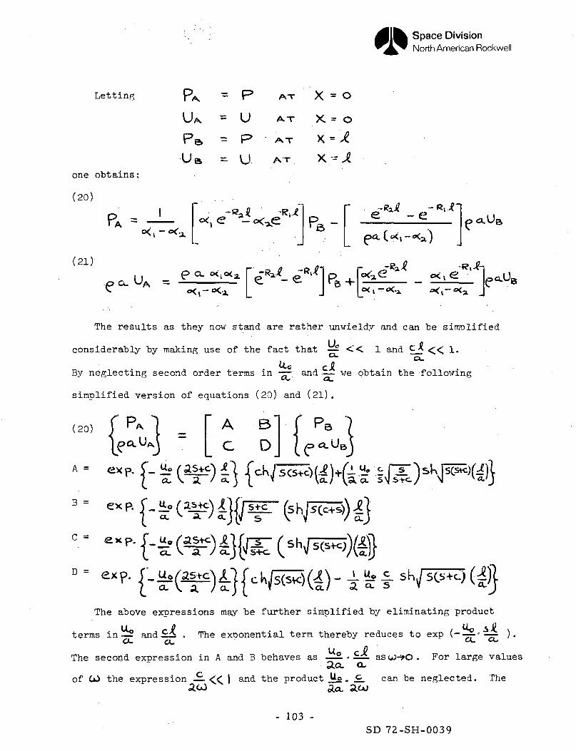
Space DivisionNorth American Rockwell
Letting
one obtains
(20)
(21)
p&UB
p a. UA =
P
U
P
U
-RL
A-r X = O
x = o
AT
P - a.Ua
<p 0. oV. 'B
The results as they now stand are rather unwieldy and can be simplified
considerably by making use of the fact that —- « 1 and C_Xo.u.c
" A
C>. rt
B"
D/• . ,_
f Ps"/ p«.UB^ » «
By neglecting second order terms in -^- and — we obtain the following
simplified version of equations (20) and (21).
(20) I "*
A =
B =
C =
D =
ex p. i - rf
ex P. f u_o f as+cVJ.
exp. I.Uo
The above expressions may be further simplified by eliminating product
~ - - " " ~terms in— andCL
The exponential term thereby reduces to exp
UThe second expression in A and B behaves as — 2. . ±. ascJ-*O. For large values
3.0. cuof the expression — « | and the product o . . can be neglected. The
- 103 -SD 72-SH-0039
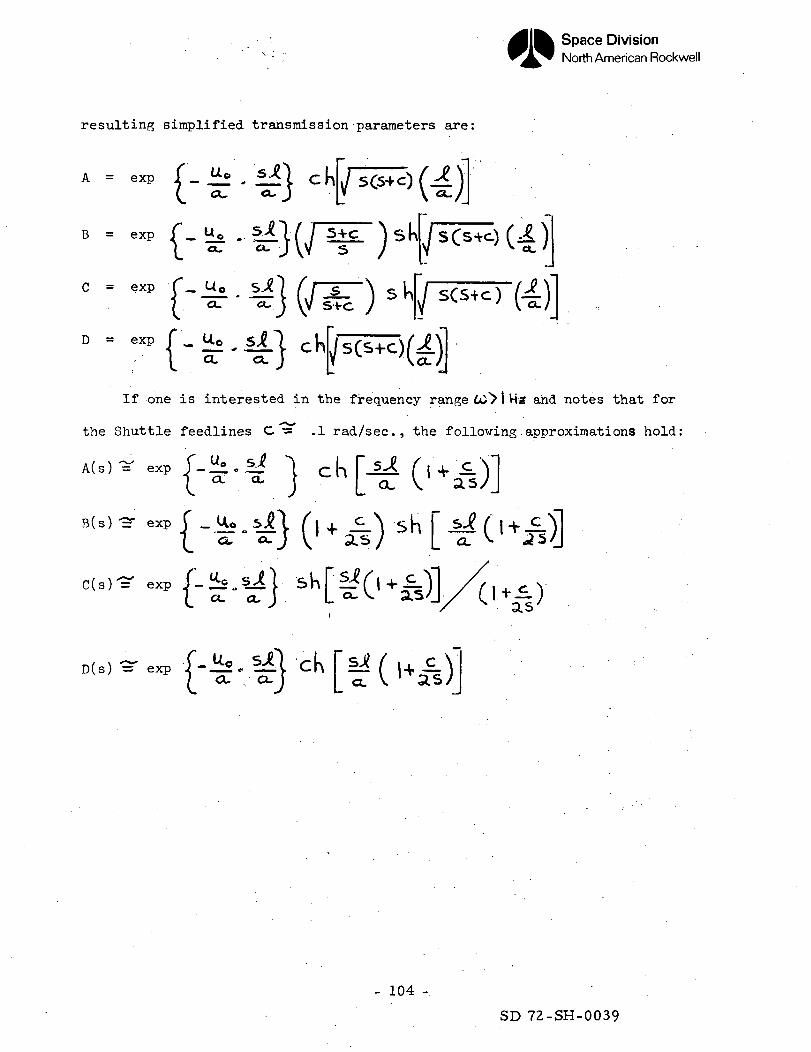
Space DivisionNorth American Rockwell
resulting simplified transmission parameters are:
A = exp 1 _ u-c> „( o*,
B = exp / _ Up f_
C = exp { __ U.o
D = exp J _ U0
If one is interested in the frequency range &)> I Hz and notes that for
the Shuttle feedlines C — .1 rad/sec., the following approximations hold:
= exp J - Zl - iila . a .
B(s) •=• exp A _
C ( s ) = exp J-:l£u%ii
D ( s ) = exp J-J±S. ^1 y u i'
- 104 -
SD 72-SH-0039
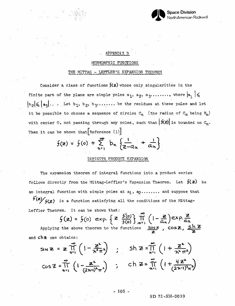
Space DivisionNorth American Rockwell
• APPENDIX B
MERMORPHIC FUNCTIONS
THE MITTAG - LEFFLER'S EXPANSION THEOREM
Consider a class of functions $Cx) whose only singularities in the
finite part of the plane are simple poles aj_, o.^ a ......... where ja,
aol^laoj.. • Let b^_, bg, bo be the residues at these poles and let
it be possible to choose a sequence of circles Cm (the radius of Cm being
with center 0, not passing through any poles, such that | Jw| is bounded on Cm
Then it can be shown that[Reference (l)J
INFINITE PRODUCT EXPANSION
The expansion theorem of integral functions into a product series
follows directly from the Mittag-Leffler's Expansion Theorem. Let £(z) be
an integral function with simple poles at a]_ , a^ ...... '.. . and suppose that
is a function satisfying all the conditions of the Mittag-
Lef fler Theorem. It can be shown that :
Applying the above theorem to the functions SIN 2 ^ COSZ.
and chi one obtains:
- 105 -SD 72-SH-0039
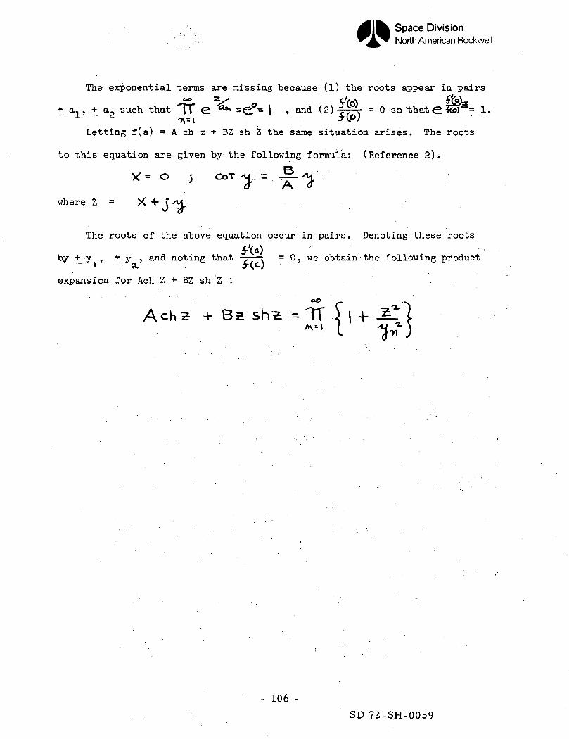
Space DivisionNorth American Rockwell
The exponential terms are missing because (l) the roots appear in pairs
+_ ais + a2 such that "TT S ** =€?- I » and (2) . = 0 so thate *efr = 1.
Letting f(a) = A ch z + BZ sh Z. the same situation arises. The roots
to this equation are given by the following formula: (Reference 2).
where Z = X 4-
The roots of the above equation occur in pairs. Denoting these roots
by+ y , + y , and noting that ^ . = 0, we obtain the following product- i - a. > (o)
expansion for Ach Z + BZ sh Z :
Ach2 4- BZ sh-2. = TTA\ - I
- 106 -
SD 72-SH-0039
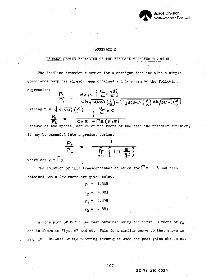
Space DivisionNorth American Rockwell
APPENDIX C
PRODUCT SERIES EXPANSION OF THE FEEDLINE TRANSFER FUNCTION
The feedline transfer function for a straight feedline with a simple
compliance pump has already been obtained and is given by the following
expression:o f ** sJttPs _ ex p. I-5:' 5TJ
Letting Z = yj SCS+c) (£) • !±f - o
Because of the special nature of the roots of the feedline transfer function,
it may be expanded into a product series.
where cot y = I y
The solution of this transcendental equation for 1= .208 has been
obtained and a few roots are given below.
y^ = 1.308
y2 = **.023
y3 = 6.898
yu = 9.883
A Bode plot of Ps/Pt has been .obtained using the first 20 roots of yn '
and is shown in Figs. 6? and 68. This is a similar curve to that shown in
Fig. 10. Because of the plotting techniques used the peak gains should not
- 107 -SD 72-SH-0039
Space DivisionNorth American Rockwell
be read off the curve shown in Pig. 6U. It is clear though that the gain
drops down with increasing frequency in the product expansion. This is the
same phenomena that occurred in the more complex Shuttle Orbiter feedline
when product expansions of the transmission parameters were used.
- 108 -
SD 72-SH-0039
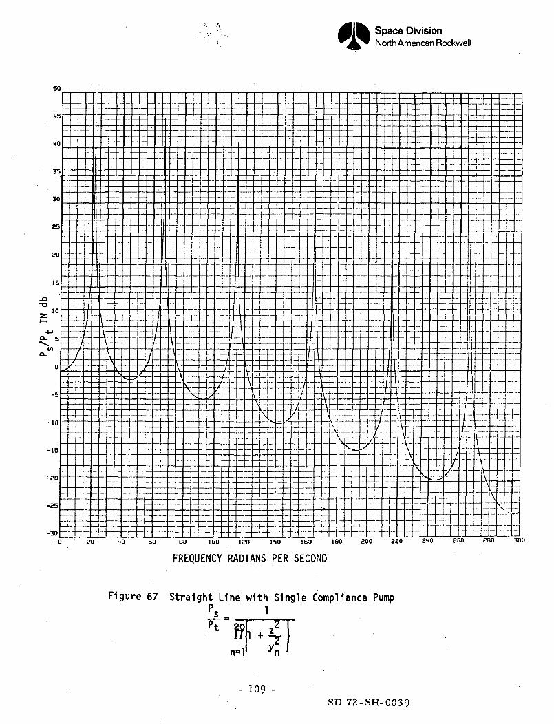
Space DivisionNorth American Rockwell
80 HO 60 80 100 ISO 140 160 180 800 230 240 ESO 280 300
FREQUENCY RADIANS PER SECOND
Figure 67 Straight Line with Single Compliance PumpPs- '
nn=l
- 109 -SD 72-SH-0039
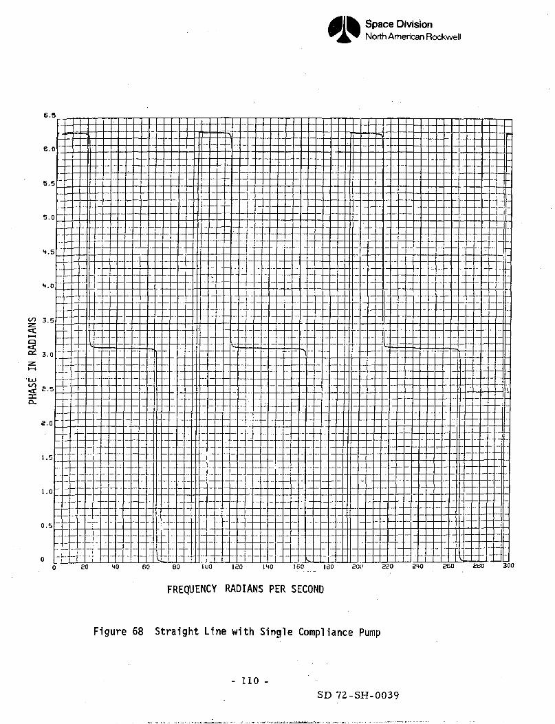
Space DivisionNorth American Rockwell
6.5
6.0
5.5
5.0
H.5
4.0
3.5
3.0
8.5
8.0
1.5
1.0
0.5
00
"
|
_
"
"80
1
V
4() 60V
(
_ ..
30
*
1
i100
"
1
1!
180 1
11
40
._
1
^ s! — •
^60 160
- — -
800
-
820 £40 860
-
.
v_8
180
•
30G
<cI—Ia
LUoo
FREQUENCY RADIANS PER SECOND
Figure 68 Straight Line with Single Compliance Pump
- 110 -SD 72-SH-0039
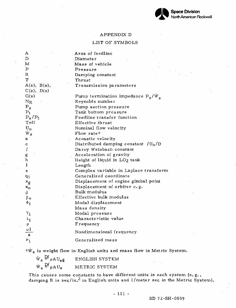
Space DivisionNorth American Rockwell
APPENDIX D
LIST OF SYMBOLS
A Area of feedlineD DiameterM Mass of vehicleP PressureR Damping constantT ThrustA(s) , B(s), Transmission parametersC(s), D(s)G(s) Pump termination impedance PS/WNR Reynolds numberPs Pump section pressurePt Tank bottom pressurePs/Pt Feedline transfer functionTeff Effective thrustU0 Nominal flow velocityWs Flow rate*a Acoustic velocityc Distributed damping constant /UO/D/ Darcy Weisbach constantg Acceleration of gravityh Height of liquid in LO2 tank1 Lengths Complex variable in Laplace transformqi Generalized coordinateXg Displacement of engine gimbal pointx0 Displacement of orbiter c. g.p Bulk moduluspe Effective bulk modulus<f>i Modal displacement
Mass densityYJL Modal pressure\i Characteristic valuep FrequencyU)l
Nondimensional frequencyct
H-J Generalized mass
*WS is weight flow in English units and mass flow in Metric System.
Ws D'pAUsg ENGLISH SYSTEM
Ws D^pAUs METRIC SYSTEM
This causes some constants to have different units in each system (e. g. ,damping R is sec/in.^ in English units and 1 /meter sec in the Metric System).
- Ill -SD 72-SH-0039