Embed Size (px)
Citation preview

Federal Department of the Environment, Transport, Energy and Communications N° 1744
Final report on
Skyguide radar systems
By the Aircraft Accident Investigation Bureau
26/06/2002 2 - 48
0 INTRODUCTION................................................................................................. 4
0.1 Primary surveillance radar (PSR)......................................................................................................... 4
0.2 Secondary surveillance radar (SSR) ..................................................................................................... 4
0.3 MRT and design of the Skyguide radar system .................................................................................. 6
0.4 The control room .................................................................................................................................... 8
1 AIR TRAFFIC INCIDENT REPORTS (ATIR) AS THE ORIGIN OF THIS INVESTIGATION........................................................................................................ 9
1.1 Summarised safety recommendations................................................................................................... 9 1.1.1 On point 1: compliance with the Eurocontrol standards for radar systems (page 9) ....................... 9 1.1.2 On point 2: completeness of the representation of the situation in the air on the ATC screen (page 29) 10 1.1.3 On point 3: definition of the “legal recording” of the situation in the air (page 41)...................... 10
2 ACCURACY OF THE RADAR SYSTEM .......................................................... 11
2.1 History ................................................................................................................................................... 11
2.2 Findings ................................................................................................................................................. 12 2.2.1 Performance required from the radar system ................................................................................ 12 2.2.2 Test flights..................................................................................................................................... 14 2.2.3 Test flight on 30 June 2000 ........................................................................................................... 15 2.2.4 Test flight on 5 December 2000 .................................................................................................... 20 2.2.5 AIRPROX on 7 May 2001 ............................................................................................................ 21
2.3 Analysis.................................................................................................................................................. 23 2.3.1 Accuracy of the situation in the air without a presentation system ............................................... 23 2.3.2 Accuracy of the SSR ..................................................................................................................... 24 2.3.3 Accuracy of the MRT.................................................................................................................... 26 2.3.4 Deviation in the presentations concerning the AIPROX on 7 May 2001...................................... 28
2.4 Summary ............................................................................................................................................... 28
2.5 Safety recommendations ...................................................................................................................... 29
3 AIR TRAFFIC WHICH DISAPPEARS FROM OR WHICH IS NOT SHOWN ON THE ATC SCREEN .................................................................................................. 30
3.1 History ................................................................................................................................................... 30
3.2 Findings ................................................................................................................................................. 32 3.2.1 Transponder faults due to microwave transmissions..................................................................... 32 3.2.2 Transponders outside the specification ......................................................................................... 32 3.2.3 ORCAM according to the example of the AIRPROX on 24 August 2000 ................................... 33 3.2.4 Exceeding capacity of elements of the radar system..................................................................... 33 3.2.5 Aircraft without transponders (primary surveillance radar) .......................................................... 37 3.2.6 Airspace without radar coverage................................................................................................... 38
3.3 Analysis.................................................................................................................................................. 38
26/06/2002 3 - 48
3.3.1 Transponder faults due to microwave transmissions..................................................................... 38 3.3.2 Transponders outside the specification ......................................................................................... 38 3.3.3 Aircraft from an adjacent ORCAM zone ...................................................................................... 39 3.3.4 Capacity and overloading of elements of the radar system ........................................................... 39 3.3.5 Aircraft without transponders (primary surveillance radar) .......................................................... 39 3.3.6 Airspace without radar coverage................................................................................................... 40
3.4 Summary ............................................................................................................................................... 40
3.5 Safety recommendations ...................................................................................................................... 40
4 LEGAL RECORDING OF THE SITUATION IN THE AIR ................................. 42
4.1 History ................................................................................................................................................... 42
4.2 Findings ................................................................................................................................................. 42
4.3 Analysis.................................................................................................................................................. 43
4.4 Summary ............................................................................................................................................... 43
4.5 Safety recommendations ...................................................................................................................... 44
5 GLOSSARY ...................................................................................................... 45
26/06/2002 4 - 48
0 Introduction Note: in this report the term “radar system” implies the entire processing chain from the radar antenna to the representation of the situation in the air on the screen of the air traffic controller (ATC): the primary and secondary surveillance radars, information transfers, the systems which combine the radar data and which track flights paths (MRT =Multi Radar Tracker) as well as the workstations which display the situation in the air to the ATC.
This report relates predominantly to the status of the systems prior to the end of the year 2000. Any improvements which have been made since are not taken into account.
The current company name “Skyguide” is also used for the former name “Swisscontrol”.
0.1 Primary surveillance radar (PSR)
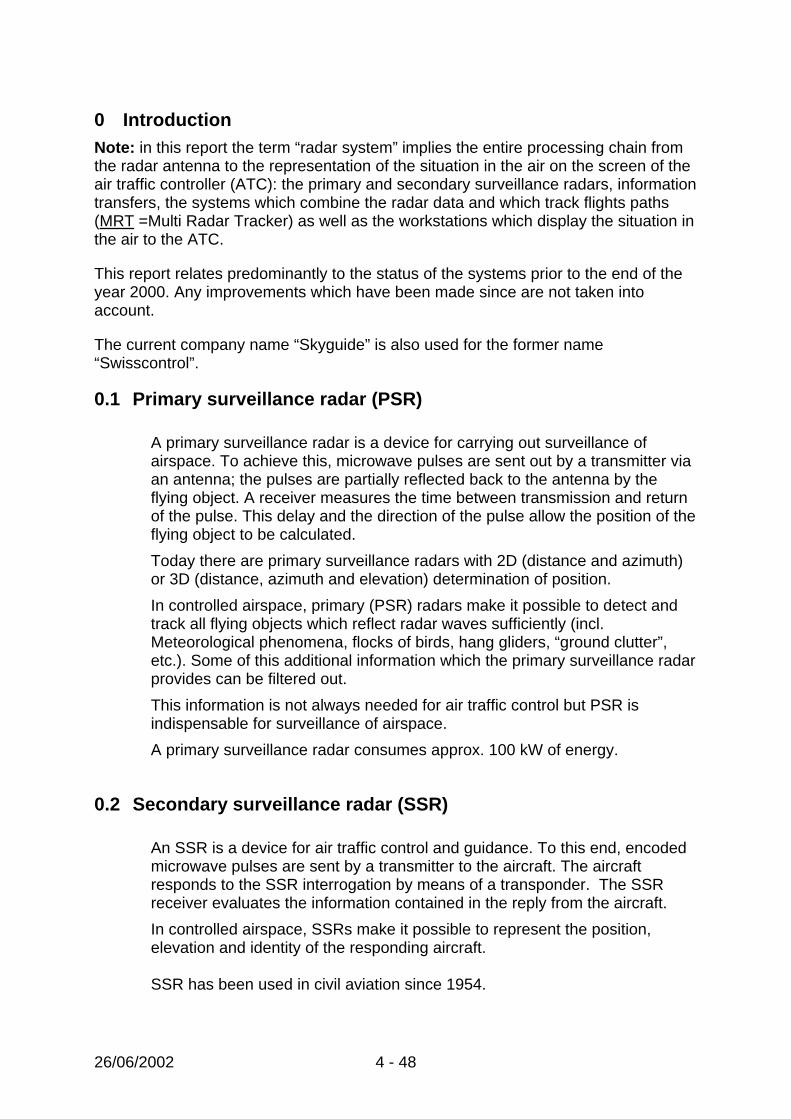
A primary surveillance radar is a device for carrying out surveillance of airspace. To achieve this, microwave pulses are sent out by a transmitter via an antenna; the pulses are partially reflected back to the antenna by the flying object. A receiver measures the time between transmission and return of the pulse. This delay and the direction of the pulse allow the position of the flying object to be calculated. Today there are primary surveillance radars with 2D (distance and azimuth) or 3D (distance, azimuth and elevation) determination of position. In controlled airspace, primary (PSR) radars make it possible to detect and track all flying objects which reflect radar waves sufficiently (incl. Meteorological phenomena, flocks of birds, hang gliders, “ground clutter”, etc.). Some of this additional information which the primary surveillance radar provides can be filtered out. This information is not always needed for air traffic control but PSR is indispensable for surveillance of airspace. A primary surveillance radar consumes approx. 100 kW of energy.
0.2 Secondary surveillance radar (SSR)
An SSR is a device for air traffic control and guidance. To this end, encoded microwave pulses are sent by a transmitter to the aircraft. The aircraft responds to the SSR interrogation by means of a transponder. The SSR receiver evaluates the information contained in the reply from the aircraft. In controlled airspace, SSRs make it possible to represent the position, elevation and identity of the responding aircraft. SSR has been used in civil aviation since 1954.
26/06/2002 5 - 48
The principle of SSR (Mode A and Mode C) does not currently allow identification and flight altitude codes to be checked for errors. A secondary surveillance radar consumes approx. 1 kW of energy.

26/06/2002 6 - 48
0.3 MRT and design of the Skyguide radar system
In Switzerland there are two “Air Traffic Control Areas of Responsibility” (=ATCAR) in Geneva and Zurich. Both control “en-route” and “approach” airspace. In Switzerland there are three long-range radar stations termed “en-route” radar (La Dôle, Lägern and TG), as well as two “approach” radar stations (Cointrin and Kloten-Holberg). In addition, four foreign radar stations are available to complete national coverage and guarantee transfer of control of the air traffic concerned to adjacent control centres (Paris, Reims, Aix, Milan, Karlsruhe, Munich, etc.).
Figure 1: Geographical location of the radar stations used by the two Swiss
ATCAR. These nine stations are all equipped with “Monopulse”-type SSRs (1985-1995 hardware generation). Some of them are also equipped with PSR. For ACC Geneva only SSR data are used. The two Swiss ATCAR use an MRT which was developed by the “Thomson-CSF” company in the early ‘eighties. The MRT in Geneva and Zurich are identical, but use the fixed predefined radar sources which are best-suited to their region or the radars with the highest-quality data, rather than all the radars which are available. The radar information can also be associated with flight plans; this makes it possible to display a callsign (e.g. SWR311) on the radar screens instead of the Secondary Surveillance Radar identification code (Mode A, e.g. A1723). In this way, the MRT ensures association of the radar data with the flight plans, for the requirements of “en-route” and “approach” ATC. The Geneva MRT is supplied with information from the following seven radar stations: Lägern, La Dôle, TG, Cointrin, Nevers, Chaumont and Mte Lésima.
Nevers
La Dôle
Cointrin
Holberg
TG
Lägern
Mte Lésima
Cirfontaine
Gosheim

26/06/2002 7 - 48
The Zurich MRT is supplied with information from the following six radar stations: Lägern, La Dôle, TG, Holberg, Gosheim and Mte Lésima.
Lägern
La Dôle
TG
Cointrin
Nevers
Chaumont
Mte Lesima
X-Clients
REC
REC
REC
REC
REC
REC
REC
REC
REC
Format AIRCAT
IPS-LeitungenFormat GP
WandlerASTERIXAIRCAT
WandlerASTERIXAIRCAT
WandlerASTERIXAIRCAT
LAN ATC
MV 9800
MRT
APP-Diffusion
ACC-Diffusion
Radarquellen :
Verarbeitung
ACC-AnzeigeICWS ICWS
X-Server X-Server
X-Clients
ICWS ICWS
X-Server X-Server
X-Clients
ICWS ICWS
X-Server X-Server
X-Clients
ICWS ICWS
X-Server X-Server
X-Clients
ICWS ICWS
X-Server X-Server
X-Clients
ICWS ICWS
X-Server X-Server
SMP
IPG
REC-Eingänge: Daten, Telefon, Funk, usw.
REC 01
S Y M A D e s k
RCMSA D A P T
Radar sources: MV 9800 processing REC inputs: Data, Telephone, Radio etc. APP distribution IPS lines GP format
Converter ACC distribution Converter Converter ACC presentation
Figure 2: Structure of the Skyguide radar system (ATCAR Geneva). The radar system shown in Figure 2 shows the radar sources and their transfer to the MRT processing system. The incoming and outgoing MRT information is recorded by the REC01 subsystem for the requirements of the “legal recording”. The “legal recording” provides, among other things, a recording of flight paths (= radar tracks)
26/06/2002 8 - 48
as well as communication between ATC and the flight crew. The information processed by the MRT is then sent out by the “IPG” interface and a LAN (= Local Area Network) to the regional control workstations. The workstations use UNIX computers, X-Window technology and large colour displays (51 cm x 51 cm). The redundancy of the different systems is not shown in the diagram. Note: In Figure 2 the elements located downstream of the MRT are part of the
ADAPT system.
0.4 The control room
In the control room, the ATCs have at their disposal colour graphics screens to display the flight paths of aircraft in a flat representation.
A flight path is shown by a symbol placed at the current position and by points for the last shown positions. Updating takes place every 12 seconds on the ATC workstations and every 4 seconds on the APP workstations. A “label” is associated with each symbol, to indicate the following values in particular:
• the flight number (“callsign”) or Mode A (A0000 – A7777)
• the flight altitude or flight level
• the calculated groundspeed (in knots) for flight paths correlated with flight plans
The number of movements controlled by an ATCAR varies over the course of a day. Since each ATC can control only a limited number of movements, the entirety of the traffic has to be distributed. This procedure is known as sectorisation. Sectorisation may be implemented, for example, according to altitude tranches. This makes it possible to distribute air traffic to between 1 and 7 control sectors for ATCs according to traffic density. The duty manager defines the sectorisation. When there is a change in sectorisation, the systems (MRT, radio and telephone links, etc.) are reconfigured in order to forward the information to the correct workstations, so that they receive only what they need.
When a sector is configured to control the airspace between flight levels FL200 to FL300, the ATC sees on his screen only those movements which take place within this range of altitudes. However, if he so desires, he can employ a special function to see all traffic. The duty manager is assisted with reconfiguration and technical monitoring of the system by a technician (SYMA). The SYMA position is connected to all terminals, monitors, management or supervisory consoles of the most important technical systems (MRT, flight plans, telephone and radio links, navigation aids, telecommunications systems, in-house automated systems, etc.). For this report, only the SMP and RCMS systems are significant with reference to the SYMA:

26/06/2002 9 - 48
SMP: workstations which are used for control and management of all the ADAPT equipment.
RCMS: PCs which are used for control and monitoring of the MV9800 computers (radar processing and flight plans).
1 Air traffic incident reports (ATIR) as the origin of this
investigation
1. In August 1998 an Air Traffic Incident Report (ATIR) was submitted to the AAIB by Skyguide. During the investigation which was initiated (Report A001) it was established that the radar tracks provided by ATC Zurich and Geneva differed, raising questions concerning quality and accuracy.
2. On 14 January 2000 and on 24 August 2000, two ATIRs concerning near-collisions were submitted to the AAIB. The investigations which were carried out (Reports A011 and A023) showed that flight paths of aircraft on the ATC screens are not displayed or may disappear.
3. Investigation of the two above-mentioned problems revealed that the recordings of flight paths by the “legal recording” may differ from the representation on the ATC screen.
These findings led the AAIB to open an investigation on the three problem areas.
1.1 Summarised safety recommendations
1.1.1 On point 1: compliance with the Eurocontrol standards for radar systems (page 9)
• The Skyguide SSR must be improved so that they meet the accuracy requirements according to the Eurocontrol standard, with particular reference to systematic errors.
• Compliance with the specifications must be proven periodically by validated
procedures or in real time.
• Updating of the MRT tracks for ATC must be reduced from 12 seconds to the 8 seconds required by Eurocontrol.
• Compliance with the accuracy requirements must be proven periodically by
evaluating the SSR and MRT systems using appropriate means.
• The SSR data and the MRT must be equipped with a common time base which is based on universal time (UTC). Until the time base is provided, it is necessary to determine the necessary minimum separation with regard to other flight control systems (GVA/ZRH, civil/military, CH/neighbouring countries) and to increase them if necessary.

26/06/2002 10 - 48
1.1.2 On point 2: completeness of the representation of the situation in the air
on the ATC screen (page 29)
• It is essential not only to ensure air traffic control (SSR) but also to ensure airspace surveillance by means of a powerful primary surveillance radar (PSR).
• The following aircraft must also be visible in the presentation of the situation in the air to the ATC:
o those whose transponder is subject to interference.
o those with a transponder which does not comply with the specifications.
o those from an adjacent ORCAM zone flying into Swiss airspace.
o those with a defective transponder.
o those flying with their transponder switched off.
• The loading on the subsystems must be regularly monitored, recorded and systematically analysed.
• Alarms which indicate an infringement of critical values must be checked periodically.
• Measures must be implemented to allow controlled reduction of the system load to below the capacity limit.
• Prior to authorising an increase in air traffic in Swiss airspace, it is urgently necessary to check whether the existing technical systems are adequate to handle such an increase.
1.1.3 On point 3: definition of the “legal recording” of the situation in the air
(page 41)
• The legal recording must be adapted to the Eurocontrol recommendation, so that a complete reconstruction at the level of the ATC console is possible. In particular, it must be possible to represent the situation in the air, the screen settings and settings on the console.

26/06/2002 11 - 48
2 Accuracy of the radar system 2.1 History
Among other things, the investigation of the near-collision of flights SWR3779/CRX985 on 15 June 1998 revealed the problem of the accuracy of the radar system. This incident took place shortly after the flights had been handed over from Geneva ATC to Zurich ATC. The radar tracks reproduced by the two ATC on paper exhibited a discrepancy in some positions of up to 1.5 NM.
Figure 3: The superimposed flight paths of the AIRPROX on 15 June 1998 according to the legal recording of the Geneva and Zurich MRT show discrepancies of up to 1.5 NM in the zone of closest approach (SWR3779 at 13:42:47). It was therefore very difficult to analyse the incident reliably on the basis of the legal recording data.

26/06/2002 12 - 48
2.2 Findings
2.2.1 Performance required from the radar system
In March 1997, Eurocontrol recognised as a standard the document “Radar Surveillance in “en-route” and Major Terminal Area” (SUR.ET1.ST01.1000-01-01). This document lays down the operational requirements for air traffic guidance and control, the requirements of radar systems and MRT, and the verification of the performance of the elements of the radar system. The operational requirements are: • (5.1) Coverage requirements
- “Comprehensive and continuous radar coverage of high quality and reliability shall be constantly available in order to achieve radar operational separations of 3 NM, 5 NM and 10 NM.”
- (4.1.2) The performance of the radar surveillance system shall enable the controller to provide a horizontal separation minimum of 5 NM in high density en-route airspace, 10 NM in other en-route airspace and 3 NM in major terminal areas.
• (5.2.1) The radar surveillance system shall provide the following information to be available for display to air traffic controllers: - aircraft horizontal position and history; - aircraft identification; - aircraft vertical position; - specific indication of Mode A special codes (i.e. 7500, 7600, 7700); - ground speed; - status of the track, whether it is primary, secondary, combined or
extrapolated.
• (5.2.4) Surveillance information updates shall enable the display updates to be no more than 5 seconds (s) for major terminal areas, and no more than 8 seconds (s) in en-route airspace. A maximum of 2 successive updates by extrapolation is acceptable for positional data.
• (5.2.3) The positional accuracy of the surveillance radar data available, at the control position, shall have an error distribution with a root mean square (RMS) value equal to or less than 500 metres (m) for en-route airspace and equal to or less than 300 metres (m) for major terminal areas.
• (5.3.2) The radar surveillance data availability requirements are: - full data availability shall be not less than 0.995, excluding periods of
scheduled maintenance; - essential data availability shall be not less than 0.99999; - PSR data availability for major terminal areas shall be not less than 0.995.

26/06/2002 13 - 48
• The availability of radar surveillance data in full and reduced system performance status and maximum outage times shall be as given in Table 1 (5.3.3).
The positional accuracy requirements for the MRT (in the case of straight constant flight and detection by at least two independent, geographically separated radars) are:
- en-route <120 m RMS along track / 120 m RMS across track (Table 7A - Accuracy Requirements En-Route)
- approach <50 m RMS along track / 50 m RMS across track (Table 5A - Accuracy Requirements Major Terminal Area)
The positional accuracy requirements for a secondary surveillance radar (SSR) are: • (6.3.3.1) Positional Accuracy
- Systematic errors: · slant range bias: < 100 m · azimuth bias (degree): < 0.1° · slant range gain error: < 1 m/NM · time stamp error: < 100 ms.
- Random errors (standard deviation values): · slant range: < 70 m · azimuth (degree): < 0.08°
- Jumps: · overall ratio of jumps: < 0.05 %·
• (6.2.3.2.1) "Jumps" are target reports with positional errors greater than 1° in azimuth or 700 m in range.
The requirements for verifying the performance of elements of the radar system are: • (8.1.1) Performance verification of the various elements of the radar chain shall
be made using procedures and analysis methods agreed within the Eurocontrol organisation.
• (8.1.2) The performances of the radar chain shall be verified prior to making operational use of the radar data.
• (8.1.3) The performances of the radar chain shall be re-assessed at regular intervals. This re-assessment can be made either by permanent monitoring (real-time quality control) or by annual performance measurement campaigns.
• (8.1.4) Changes in operational requirements or replacement of any element of the radar chain, which may have an impact on radar data quality shall require re-verification of performance.

26/06/2002 14 - 48
2.2.2 Test flights
Two test flights were conducted on 30 June 2000 and on 5 December 2000. The flight paths of the aircraft were recorded onboard using a Global Positioning System (GPS) receiver, a Trimble 4000 SSE, and then corrected to differential GPS (DGPS) data with data acquired by the ground reference stations of the AGNES network or a reference receiver at reference points in Emmen or Berne. The DGPS data provide the three-dimensional position of the aircraft at a rate of one dataset per second. The accuracy of the flight path is of the order of a few metres. The DGPS data were compared with the data recordings of the MRT and individual radars made by the “legal recording” at Geneva and Zurich. A statistical analysis of these data was then carried out in order to calculate the systematic and random errors according to the Eurocontrol standard for each of the radar sources (SSR) and for processing of the data by an MRT respectively. Additional information on the procedure The MRT updates the data every 12 seconds for the ATC and every 4 seconds for the APP. The legal recording records the radar data at the same intervals. The DGPS data were converted from WGS-84 coordinates into national coordinates. The MRT radar data takes the form of system coordinates with a reference point of Cointrin for GVA and Holberg for ZRH. These coordinates are projected onto national coordinates with Berne as a reference point (600,000/200,000) by transformation into a geocentric system. The SSR data related to the radar location. For purposes of comparison, the DGPS data were transformed to the corresponding radar location. Since the SSR requirements relate to azimuth and range, both the SSR and the transformed DGPS data were converted into polar coordinates. The altitude of the aircraft is indicated by GPS as the geographic altitude above the ellipsoid of the earth, whilst radar reproduces the Mode C pressure altitude. Depending on the meteorological conditions (atmospheric pressure distribution), the two altitude indications may differ. The difference may be more than 100 m. For the analysis of positional accuracy, pressure altitude was replaced by DGPS altitude.
26/06/2002 15 - 48
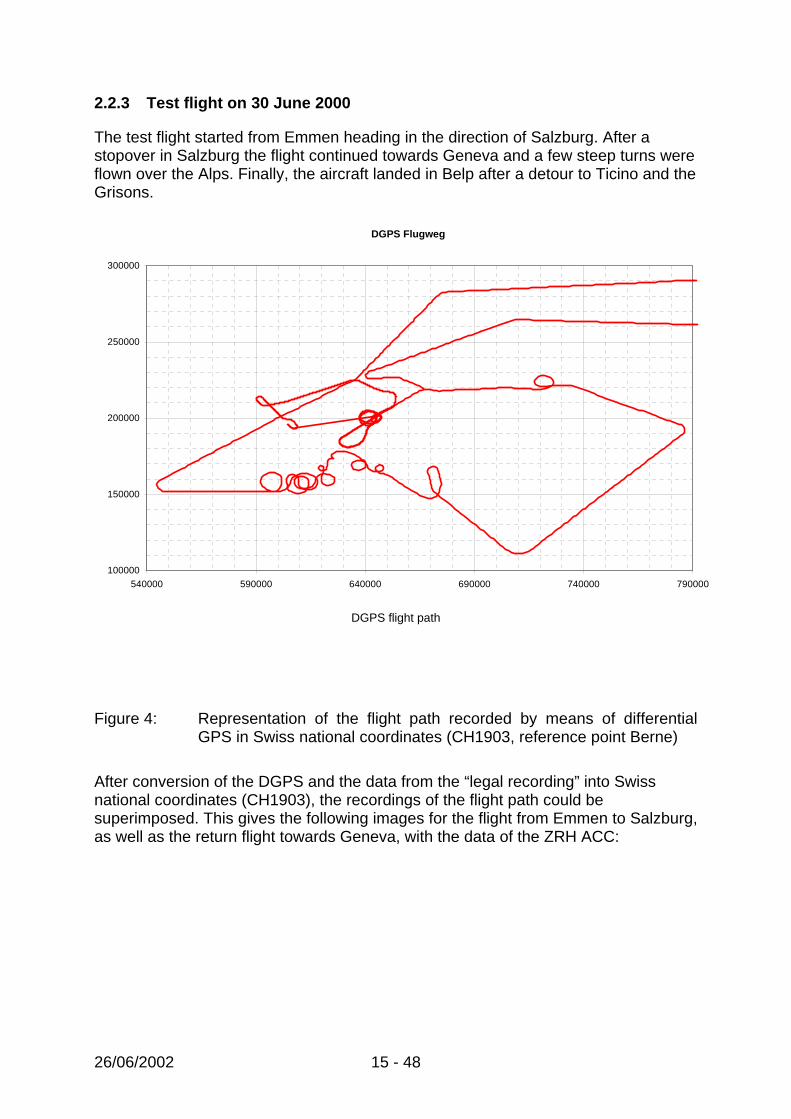
2.2.3 Test flight on 30 June 2000
The test flight started from Emmen heading in the direction of Salzburg. After a stopover in Salzburg the flight continued towards Geneva and a few steep turns were flown over the Alps. Finally, the aircraft landed in Belp after a detour to Ticino and the Grisons.
DGPS flight path
Figure 4: Representation of the flight path recorded by means of differential GPS in Swiss national coordinates (CH1903, reference point Berne)
After conversion of the DGPS and the data from the “legal recording” into Swiss national coordinates (CH1903), the recordings of the flight path could be superimposed. This gives the following images for the flight from Emmen to Salzburg, as well as the return flight towards Geneva, with the data of the ZRH ACC:
DGPS Flugweg
100000
150000
200000
250000
300000
540000 590000 640000 690000 740000 790000

26/06/2002 16 - 48
150000
180000
210000
240000
270000
300000
540000 580000 620000 660000 700000 740000 780000 820000
ACC ZRHDGPS
Figure 5: Flight path of ACC ZRH compared with the flight path according to
differential GPS.
173000
178000
183000
188000
193000
198000
203000
208000
565000 570000 575000 580000 585000 590000 595000 600000 605000 610000 615000
ACC ZRHDGPSLAG
Figure 6: Detailed extract from Figure 5 in the Berne area shows a deviation of
the MRT for ACC ZRH from the DGPS reference. The data for the Lägern radar (LAG) are shown for purposes of comparison.

26/06/2002 17 - 48
A detailed view of the Berne area shows a deviation in the MRT data (ACC ZRH) from the DGPS reference, whilst the Lägern radar remains close to the DGPS flight path. GVA only provided data for the part of the flight over the Alps, prior to the landing in Belp. This provided the following overview.
180000
185000
190000
195000
200000
205000
210000
215000
220000
225000
230000
580000 590000 600000 610000 620000 630000 640000 650000 660000
GVA_ACCDGPS
Figure 7: Comparison, ACC GVA with the flight path according to differential
GPS.
210000
215000
220000
225000
230000
610000 615000 620000 625000 630000 635000 640000
GVA_ACCDGPSDOLLAG
Figure 8: Comparison of the GVA MRT data for ACC, the individual radars DOL
and LAG, and differential GPS. One square represents an area of 1 km x 1 km.

26/06/2002 18 - 48
A detailed view of the approach to Berne with the deviations shows that ACC GVA and DOL deviate by up to several kilometres from the DGPS flight path, whilst LAG follows the reference more closely. If at the same time the deviation between the Skyguide data (the record of the “legal recording”) and the DGPS reference is calculated, the positional error which occurred for the flight path in question is obtained. The altitude error is not taken into consideration because of the unknown difference between pressure altitude and GPS altitude. If one calculates the speed from two successive position datasets and the time which separates them, any position errors in the flight direction can be more easily viewed than by showing the positions alone.

26/06/2002 19 - 48
The two sections of the flight for which ZRH provided the ACC data produce the following graphs.
ACC ZRH
0
100
200
300
400
500
600
700
6:08 6:11 6:14 6:17 6:20 6:23 6:25 6:28 6:31 6:34 6:37
Zeit (UTC)
Abw
eich
ung
AC
C-D
GPS
[m]
10
40
70
100
130
160
190
Ges
chw
indi
gkei
t [m
/s]
ACC-GPSv_ACCv_DGPS
ZRH ACC
0
200
400
600
800
1000
1200
9:00 9:07 9:14 9:21 9:28 9:36 9:43 9:50
Zeit (UTC)
Abw
eich
ung
AC
C-D
GPS
[m]
80
100
120
140
160
180
200
Ges
chw
indi
gkei
t [m
/s]
ACC-GPSv_DGPSv_ACC
ZRH LAG
0
200
400
600
800
1000
1200
9:00 9:07 9:14 9:21 9:28 9:36 9:43 9:50
Zeit (UTC)
Abw
eich
ung
LAG
-DG
PS [m
]
80
100
120
140
160
180
200
Ges
chw
indi
gkei
t [m
/s]
LAG-GPSv_DGPSv_LAG

26/06/2002 20 - 48
Figure 9: Horizontal deviations between the ZRH MRT data for ACC and DGPS, plus, for comparison, the Lägern SSR. The right-hand scale refers to the speeds derived from the position datasets.
ACC GVA
0
500
1000
1500
2000
2500
3000
3500
4000
4500
12:28 12:36 12:43 12:50 12:57 13:04
Zeit (UTC+1h)
Abw
eich
ung
AC
C-D
GPS
[m]
0
50
100
150
200
250
300
350
400
450
500
Ges
chw
indi
gkei
t [m
/s]
ACC-GPSv_ACCv_DGPS
Time
Figure 10: Horizontal deviations between the GVA MRT data for ACC and DGPS, plus the speeds derived from the position datasets.
2.2.4 Test flight on 5 December 2000
The test flight flew from Dübendorf to Salzburg, then, after a stopover, from Salzburg towards Geneva, and back to Dübendorf after a detour to Locarno.
500 600 700 800 900 1000 1100100
150
200
250
300
350
GPSRadarHolberg 1
500 600 700 800 900 1000 1100
100
150
200
250
300
350
GPSRadarHolberg 1
Figure 11: Flight path of the test flight on 5 December 2000 according to
recordings using differential GPS and the MRT data of ACC Zurich (left), and APP Zurich (right), both converted to Swiss national coordinates (CH1903, axes in km instead of m).

26/06/2002 21 - 48
The Berne – St.Prex – Berne leg was recorded by MRT GVA. The database is far too small for an analysis of the December test flight according to “positional jumps”. According to the Eurocontrol standard, a radar must on average give less than 1 positional jump for every 2000 position signals. The test flight, however, provided distinctly fewer than 2000 position signals, since 2000 positions will occur only in 6.7 hours for a 12 second cycle, or 2.8 hours for a 5 second cycle. 2.2.5 AIRPROX on 7 May 2001
An ATIR by ACC GVA reported a near-collision (AIRPROX) between a civil aircraft (BZH 842) and a Swiss military jet aircraft (F5): “CH MIL TFc is approaching BZH 842 from the east with high speed and high rate of climb.” The ATC reported an approach as close as 2 NM at flight level FL 350. The TCAS on the civil aircraft indicated a collision warning. The analyses of the Skyguide and FLORIDA radar recordings provide the following graphics:
Figure 12: A patrol of F5 (Tiger) aircraft approached civil aircraft BZH 842
from the north-east in a climb. At 12:08:52 (ACC system time, UTC time zone) the patrol reached the flight level of the civil aircraft at a distance of 4 NM (7.4 km). At the next update of the ACC data, the following situation was shown on the ATC’s screen: one F5 had separated from the patrol and was on a direct heading for the civil

26/06/2002 22 - 48
aircraft. The separation was less than 2 NM (3.6 km). Only after a further 12 seconds did it become visible that the F5s, after a steep left turn, were travelling away from the civil aircraft in a south-easterly direction.
Figure 13: The same situation as in Figure 12 according to the FLORIDA data. At
12:08:46 (UTC) the patrol initiates a steep left turn south-east at a distance of 5.1 NM (9.5 km). After completing the manoeuvre, at 12:09:09 the F5s were again 5.7 NM (10.5 km) from the civil aircraft BZH 842. The minimum separation between the aircraft within this period cannot be determined precisely from the available data. According to FLORIDA data, it was not less than 4 NM (7.4 km).
ACC GVA and FLORIDA differ in particular with regard to the minimum separation of the encounter between the civil aircraft BZH 842 and the Swiss air force F5. For the ATC in Geneva, a minimum separation of 2 NM was shown for flight directions on a possible collision course, whilst FLORIDA indicated a minimum distance of 4 NM with opposite flight directions.

26/06/2002 23 - 48
2.3 Analysis
2.3.1 Accuracy of the situation in the air without a presentation system
The difference in geographical positions (excluding altitude) between the MRT and the GPS data at the same time defines the positional accuracy of the situation in the air at the output from the MRT, but without taking into account the characteristics of the presentation system. Eurocontrol demands that radar data be stamped with a UTC time stamp and recommends that “time systems used for time stamping radar data should be synchronized to a common standard UTC source operating to an accuracy of +/- 5 ms.” The MRT data are linked to the MRT system time. The dating (time stamping) of the position information of an SSR is provided by the system time of the MRT corrected for the processing and transfer time, plus the antenna rotation time from north to the azimuth of the position. GPS time can be converted accurately to UTC by calculating the number of seconds elapsed at the time of the test flight. The time difference of unknown magnitude between the GPS and radar data due to the absence of a UTC time stamp leads to positional differences depending on the airspeed and direction. This error component must be taken into account in the overall error.
0
100
200
300
400
500
600
0 200 400 600 800 1000 1200 1400 1600
x [m]
y [m
]
Figure 14: Example of difference in position in the direction of flight, with a time difference of 3 seconds between UTC (green) and MRT system time (violet) at airspeeds of 250 (flying left), and. 200 m/s (flying right).
For the test flight on 30 June 2000 this produces the following accuracies, compared with the operational requirements of the overall system according to Eurocontrol.
1 2 3 4 5 6 Sec.
Sec. 6 5 4 3 2
26/06/2002 24 - 48
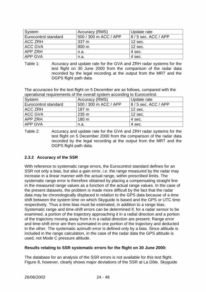
System Accuracy (RMS) Update rate Eurocontrol standard 500 / 300 m ACC / APP 8 / 5 sec. ACC / APP ACC ZRH 337 m 12 sec. ACC GVA 800 m 12 sec. APP ZRH n.a. 4 sec. APP GVA n.a. 4 sec.
Table 1: Accuracy and update rate for the GVA and ZRH radar systems for the test flight on 30 June 2000 from the comparison of the radar data recorded by the legal recording at the output from the MRT and the DGPS flight path data.
The accuracies for the test flight on 5 December are as follows, compared with the operational requirements of the overall system according to Eurocontrol. System Accuracy (RMS) Update rate Eurocontrol standard 500 / 300 m ACC / APP 8 / 5 sec. ACC / APP ACC ZRH 187 m 12 sec. ACC GVA 235 m 12 sec. APP ZRH 180 m 4 sec. APP GVA n.a. 4 sec.
Table 2: Accuracy and update rate for the GVA and ZRH radar systems for the test flight on 5 December 2000 from the comparison of the radar data recorded by the legal recording at the output from the MRT and the DGPS flight path data.
2.3.2 Accuracy of the SSR
With reference to systematic range errors, the Eurocontrol standard defines for an SSR not only a bias, but also a gain error, i.e. the range measured by the radar may increase in a linear manner with the actual range, within prescribed limits. The systematic range error is therefore obtained by placing a compensating straight line in the measured range values as a function of the actual range values. In the case of the present datasets, the problem is made more difficult by the fact that the radar data may be chronologically displaced in relation to the GPS data because of a time shift between the system time on which Skyguide is based and the GPS or UTC time respectively. Thus a time bias must be estimated, in addition to a range bias. Systematic range and time-shift errors can be determined if, for a radar sensor to be examined, a portion of the trajectory approaching it in a radial direction and a portion of the trajectory moving away from it in a radial direction are present. Range error and time-shift error are then summated in one portion of the trajectory and deducted in the other. The systematic azimuth error is defined only by a bias. Since altitude is included in the range calculation, in the case of the radar data the GPS altitude is used, not Mode C pressure altitude. Results relating to SSR systematic errors for the flight on 30 June 2000: The database for an analysis of the SSR errors is not available for this test flight. Figure 8, however, clearly shows major deviations of the SSR at La Dôle. Skyguide

26/06/2002 25 - 48
determined in the analysis that at the time of the test flight a defective SSR channel from La Dôle was being transmitted to the MRT in Geneva. Results relating to SSR systematic errors for the flight on 5 December 2000: With reference to the Geneva data, the legs of the flight Berne-St.Prex-Berne from La Dôle and Lägern are suitable for analysis.
The Zurich SSR data exhibit fewer portions of radial flight paths and produce less accurate evaluations for Lägern and Hohlberg:
ATC SSR Part of
flight
Time shift [sec]
Range bias [m]
Range gain error [m/NM]
Azimuth bias[deg]
EC Standard 0±0.1 100 m 1 m/NM 0.1° GVA DOL 2 2.1±0.2 230±20 -3.1±0.3 0.05±0.005 GVA LAG 2 2.1±0.2 180±20 -0.5±0.2 -0.01±0.002ZRH HOL1 1 -1±1 300±50 -3±0.3 0.25±0.1 ZRH LAG 1 1±1 300±50 -2.7±0.3 0.03±0.04
Table 3: Comparison between maximum admissible values according to the Eurocontrol standard and the systematic errors determined
The random errors of the SSRs in azimuth and range are described by the standard deviation after prior correction of the systematic errors. In the case of azimuth, the systematic error described by a bias alone need not be subtracted, since this is by definition taken into consideration in the standard deviation. In the case of range,

26/06/2002 26 - 48
subtraction of the systematic error is necessary because of the portion which increases in a linear fashion. Using the systematic errors shown in table 3, it is possible to produce the following random errors for the SSR.
ATC SSR Part of flight
Range mean[m]
Range Stdev[m]
Azimuth mean [deg]
Azimuth Stdev[deg]
EC Standard -- 70 m, ---- 0.08° GVA DOL 2.1 16.5 56.6 0.001 0.026 GVA DOL 2.2 -15.4 48.9 0.001 0.031 GVA LAG 2.1 25.3 43.6 0.001 0.021 GVA LAG 2.2 -27.5 113.7 0.001 0.040 ZRH HOL1 1.1 -3.4 59.2 0.298 0.151 ZRH HOL1 1.2 43.8 92.1 -0.197 0.066 ZRH LAG 1.1 -56.1 54.3 -0.001 0.036 ZRH LAG 1.2 88.7 95.2 0.034 0.040
Table 4: Random errors of SSRs after correction of the systematic errors, determined separately in each case for legs of the flight towards and away from the radar. The mean values should be close to zero after correction of the systematic errors.
The radars (SSR Lägern, La Dôle and Holberg) measured by the test flight on 5 December, under optimal conditions, all show at least one parameter with an excessively high systematic error. The range bias and the range gain error in particular were exceeded. However, only in the case of Hohlberg was the azimuth bias exceeded. After correction of the systematic errors, Lägern still presents excessively high random range errors, as does Holberg for azimuth and range errors. The Eurocontrol requirement for a time stamp to a 0.1 second accuracy is not met. 2.3.3 Accuracy of the MRT
Only data from the test flight on 5 December 2000 were analysed. Statistical data which could be analysed are available only for ACC Geneva and APP Zurich. MRT errors are described in the EUROCONTROL Standard by the RMS errors “along” and “across track”. The RMS error differs from a standard deviation in that no mean value of the difference between radar and reference path (GPS) is subtracted. Systematic errors are therefore incorporated in the RMS error (note the difference from the specifications for SSR azimuth and range, where the error is explicitly split into systematic and random components. Depending on the target cinematics, different upper admissible error limits are set – for a uniform straight movement, a standard turn, a straight movement with uniform acceleration, and a uniform climb or descent. With the data available, only straight uniform flight paths could be investigated. Part 3 describes the straight parts of the Berne-Lugano-Dübendorf leg of the flight, e.g. 3.5 according to Figure 15:

26/06/2002 27 - 48
Figure 15: Flight path part 3.5 according to Zurich MRT/APP with the
corresponding differences from the GPS reference path along and across track. The dotted red lines encompass 95% of the values.
ATC MRT Part of
flight Along-track
RMS [m] Across-track
RMS [m] Along-track Stdev [m]
Across-trackStdev [m]
EC Standard 120 m 120 m n.a. n.a. GVA ACC 2.1 442.8 116.4 42.6 113.2
GVA ACC 2.2 146.6 134.5 56.1 71.4
Table 5: RMS errors along and across track of Geneva and Zurich MRTs,
compared with the requirements of the Eurocontrol standard for “en-route”.
ATC MRT Part of flight
Along-track RMS [m]
Across-trackRMS [m]
Along-track Stdev [m]
Across-trackStdev [m]
EC Standard 50 m 50 m n.a. n.a.

26/06/2002 28 - 48
ZRH APP 1.1 197.3 135.5 153.9 132.8
ZRH APP 1.2 81.0 125.0 49.2 74.1
ZRH APP 3.1 82.2 157.4 51.4 51.6
ZRH APP 3.2 158.6 114.9 40.5 81.3
ZRH APP 3.3 139.5 126.3 44.2 114.9
ZRH APP 3.4 174.1 139.4 125.6 39.7
ZRH APP 3.5 94.7 110.0 64.3 106.1
Table 6: RMS errors along and across track of Geneva and Zurich MRTs, compared with the requirements of the Eurocontrol standard for “approach”
The RMS values of the MRT position errors exceed the Eurocontrol values in 17 out of 18 cases. The MRT essentially reproduces the errors of the dominant radar source. 2.3.4 Deviation in the presentations concerning the AIPROX on 7 May 2001
The following point of comparison can be reliably established from Figure 12 for ACC GVA and Figure 13 for FLORIDA: at 12:08:46, for FLORIDA, the F5s were flying towards BZH 842 at a separation of 9.5 km. For ACC GVA the interpolated distance at that time was only 8.4 km. It is highly probable that this difference is attributable to the different times in the two radar systems. The minimum separation, which differs by a factor in excess of 2, and the very different tracks at that time are attributable to a positional jump in the GVA radar data. An exact reconstruction of the AIRPROX is made considerably more difficult by the time difference between the two systems and by the positional jump. The incorrect presentation of the situation in the air, however, is of considerable importance in both radar systems, especially for the management of aircraft by ATC. 2.4 Summary
In the case of the test flight on 30 June 2000, Geneva was working with a defective channel of the La Dôle SSR. Consequently the RMS value of 500 m specified by Eurocontrol, which is a prerequisite for the minimum separation of 5 NM, was exceeded. The Eurocontrol requirement for a common time reference – “coordinated universal time (UTC) as specified in ICAO Annex 5 shall be used to time stamp radar data” – was not met by Skyguide. With particular reference to coordination with the flight control systems of neighbouring countries and military airspace surveillance, this is a serious matter, because time differences between the different systems of only a few seconds are sufficient to degrade the accuracy of the position of aircraft by more than

26/06/2002 29 - 48
500 m at the intersections between the systems. If the 500 m is exceeded, the accuracy requirement for separation can no longer be complied with. The values derived from the test flight of 5 December 2000 for accuracy of the SSR show that the SSR's random errors partially meet the Eurocontrol requirements. However, none of the SSR meets all the requirements concerning systematic errors. The design of the Skyguide MRT means that its accuracy is determined as a function of the accuracy of the dominant radar in the corresponding mosaic of the MRT. However, SSR accuracy is made even worse because the SSR measurements are extrapolated on the MRT’s time frame, or because missing altitudes are set to zero, and this may lead to projection errors depending on distance from the SSR. The Skyguide MRT generally exceeds the accuracy tolerances for tracking an aircraft which is flying in a straight line by several times over, even under the optimal conditions present during the test flight on 5 December 2000. The accuracy of the presentation on the ATC console, measured at the output from the MRT is not always sufficient to maintain minimum separation. The test flight on 30 June 2000, however, showed that it is possible to work for an unspecified period with a defective system which no longer met accuracy requirements, without being aware of this. 2.5 Safety recommendations
• Skyguide SSR must be improved so that they meet the accuracy requirements according to the Eurocontrol standard, particularly with regards to systematic errors.
• Compliance with the specifications must be proven by means of validated
procedures, periodically or in real time.
• Updating of the MRT tracks for the ACC must be reduced from 12 seconds to the 8 seconds required by Eurocontrol.
• Compliance with the accuracy requirements must be proven periodically by
analysing the SSR and MRT systems by appropriate means.
• The SSR data and the MRT must be equipped with a common time base which is based on universal time (UTC). Until the time base is provided, it is necessary to determine the minimum separation at the intersections with other flight control systems (GVA/ZRH, civil/military, CH/neighbouring countries) and to increase them if necessary.

26/06/2002 30 - 48
3 Air traffic which disappears from or which is not shown on the ATC screen
3.1 History
The following incident on 2 December 1999 was reported to the AAIB: "A traffic incident was narrowly avoided between an aircraft flying to Geneva
(TAR 700, descent stopped at the last minute) and an aircraft in transit at flight level 240 (RGI 672K) not shown on the ICWS radar of the control sector concerned (KINES). Furthermore, the radar operator for the 6th sector (adjacent physical position) did not see this aircraft on his screen after carrying out the appropriate manipulation. This aircraft was displayed correctly only after the code requested by Geneva was displayed”.
The ATC personnel describe the problem as follows: "ICWS may not display an aircraft in the sector to which it is allocated, or in
other sectors in which it should also be visible under a different status or after an appropriate manipulation”.
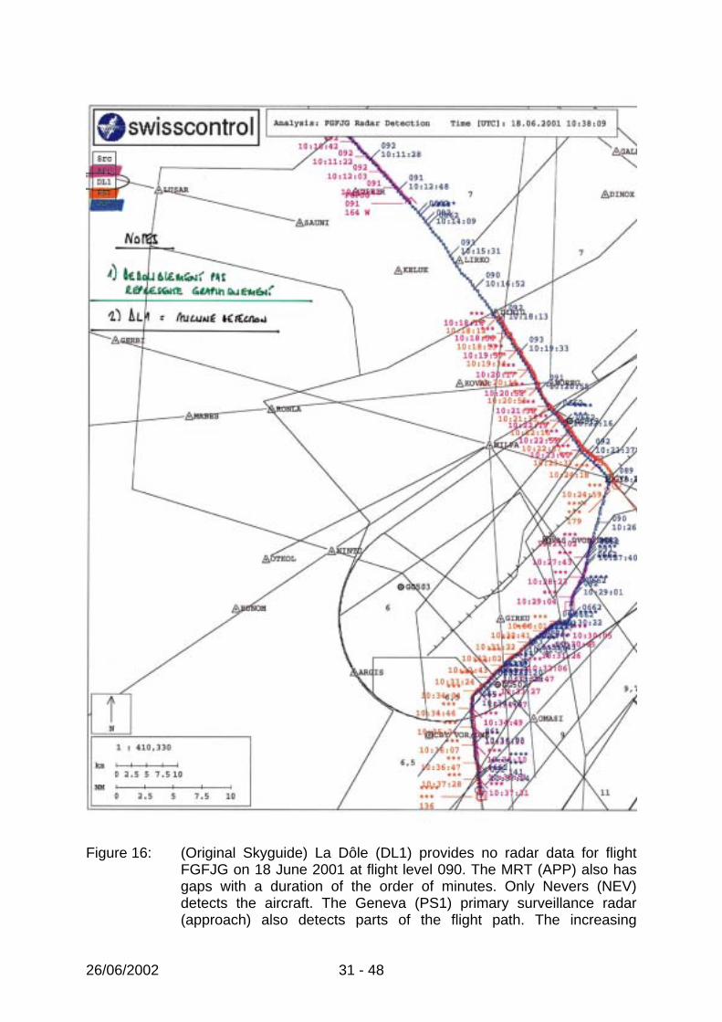
On 20 May 2001, ACC GVA filed two ATIRs concerning the disappearance of aircraft from ATC screens: At 08:06 (UTC), CFG 909 (a Boeing 753) and A2A 318 (an MD 82) crossed at flight level 350 20 NM south-west of Aosta. The controller reported: “During radar separation between CFG 909 and A2A 318 radar contact is lost with CFG 909 just before crossing the track (~10 NM)”. At 09:40 a similar incident was repeated between an MD 87 and an A 306 (Airbus 300-600) over OMETA: “While radar separation is in progress between OAL 201 and JKK 103, OAL 201 disappears completely from the screen. Req. of IDENT brings him back ~1 MIN.” There are also reports from GVA APP of aircraft which were not seen. One example is referred to in an ATIR dated 18 June 2001: “LACK OF RADAR (MRT) DETECTION BTN KELUK AND LIRKO. ACFT ONLY SEEN BY NEVERS RADAR. ACFT “SEEN” USING “FALLBACK”. BTN GVA AND SALEV, ONLY SEEN BY NEVERS RADAR. NEARLY NO MRT, LA DOLE OR ASR10 DIDN’T PICK UP ACFT CORRECTLY”. This report concerned FGFJG (a C 185) at Flight Level 90, descending, presented in the following summary:
26/06/2002 31 - 48
Figure 16: (Original Skyguide) La Dôle (DL1) provides no radar data for flight
FGFJG on 18 June 2001 at flight level 090. The MRT (APP) also has gaps with a duration of the order of minutes. Only Nevers (NEV) detects the aircraft. The Geneva (PS1) primary surveillance radar (approach) also detects parts of the flight path. The increasing

26/06/2002 32 - 48
deviation between NEV and PS1 is attributable to projection errors on the PS1 data, which do not have altitude information.
3.2 Findings
In the course of the investigation, six possibilities were established which may lead to aircraft not being shown on screen:
• Transponder faults due to microwave transmissions • Transponders which do not meet the specifications • Aircraft arriving from an adjacent ORCAM zone and which have been filtered
out by the competent ATC’s ICWS workstation • Traffic volume exceeds the capacity of elements of the radar system • Aircraft without transponders, or with defective transponders or transponders
which have been deliberately switched off (no PSR) • Airspace without radar coverage
3.2.1 Transponder faults due to microwave transmissions
As described in section 3.1, aircraft have repeatedly disappeared from the radar screen over the Aosta region. An analysis carried out by Skyguide has shown that microwave transmissions are made in the region in the 1030 MHz frequency range. This interferes with the transponder receiver, as the SSR (uplink) interrogation frequency is 1030 MHz. 3.2.2 Transponders outside the specification
The American Federal Aviation Authority (FAA) has conducted a study on compliance with transponder specifications: “A Field Study of Transponder Performance in General Aviation Aircraft” (DOT/FAA/CT-97/). The study comes to the following conclusions: “Only 4 percent of the sample transponders that were tested during this study were able to meet performance specifications on all 31 test parameters. Examination of the test parameters that were commonly failed, and the magnitude of the performance deviations on these parameters, indicated that many of the detected problems would not materially affect the transponder’s ability to operate with existing secondary radar and Traffic Collision Avoidance System (TCAS) processors. However, an analysis of the operational implications of some of the failures showed that approximately 17 percent of the transponders would create functionally significant problems when interacting with ground Secondary Surveillance Radar (SSR) processors, TCAS, or both. These problems included 12 percent of the transponders that would not be detected by an interrogator or would experience intermittent detection failures. Some of the detailed findings obtained in this study were unexpected and are particularly noteworthy. Results identified a second make/model of transponder that sometimes exhibits an operational flaw originally detected in Terra transponders. These transponders fail to reply consistently to interrogations used by the Mode Select (Mode S) radar system and by TCAS to acquire targets. This failure prevents

26/06/2002 33 - 48
the transponders from being detected by TCAS, and would be invisible to Mode S radar if the modification introduced to deal with the Terra transponders were removed from the Mode S processor. A second notable finding was that a large number of transponders either exhibited significant altitude errors or failed to report an altitude during testing. The result indicates that the warm-up time required for transponder/altitude encoders to achieve acceptable performance might be much longer than is commonly believed. Thirty percent of the transponders failed at least one of the seven tests that must be performed as part of the biennial inspection required by FAR Part 43. The average transponder in the sample had received its last biennial inspection approximately 16 months prior to being tested in the study. However, the data indicate that there was no correlation between the time since last inspection and the number of biennial test failures. Although acceptable performance was not predicted by how recently a transponder had received its biennial inspection, it was significantly associated with the pilot’s use of air traffic control (ATC) radar services. Less than one-half as many transponders owned by pilots who had recently flown Instrument Flight Rules (IFR) or used Visual Flight Rules (VFR) flight following failed an operationally significant test than those owned by pilots who had not used radar services. This result suggests that pilots who use radar services may be using any feedback they receive from ATC as a basis for transponder maintenance decisions.” 3.2.3 ORCAM according to the example of the AIRPROX on 24 August 2000
As part of the investigation into an AIRPROX between SWR 302 (an Airbus 321) and SWR 3633 (a Saab 2000) on 24 August 2000 it was established that the ZRH MRT only displays the flight track correlated with the flight plan data if these display the designated transponder code for the corresponding Zurich sector. Uncorrelated flight tracks may be filtered from the presentation on the ATC console by the workstation. ORCAM (Originating Region Code Assignment Methodology) is a procedure for assigning the SSR transponder code according to the rules of the ICAO Air Navigation Plan, European Region. The ORCAM rules are intended to minimise both the number of identical codes in the region concerned and the number of code changes during the flight. During the AIRPROX on 24 August 2000, SWR 3633 was flying from Genoa to Zurich, still under the area of responsibility of Milan Control and was not detected by the competent Zurich ATC.
3.2.4 Exceeding capacity of elements of the radar system
All elements of the processing chain from the radar to the console have a limited processing capacity as well as a limited transmission capacity to the next element in the chain. The capacities define the maximum number of flight paths in the detection range (e.g. 360° azimuth, up to maximum range and maximum altitude for a radar). In addition to these total loading limits, there are also limits for parts of the detection range (e.g. azimuth sector for radar), which define the possible peak loads. These peak loads are not considered.

26/06/2002 34 - 48
In a reply dated 31 March 2000, Skyguide gives the values for the MRT ZRH: “In ZRH, the load limit is currently 350 simultaneously processed tracks; this value has never been reached to date in practical operation. The highest load ever recorded was 308 tracks.” Skyguide refers to the built-in alarms in the MRT and ADAPT, which have never been triggered. However, Skyguide wrote on 31 March 2000: “The limit on the number of processed tracks is defined both by the software in use and by limitations of the installed hardware. An investigation is currently in progress to determine how far these limits can be further increased with the current system.” Statement by Skyguide on 11 October 2000 concerning MRT Geneva: “The maximum load of the MRT is currently 220 tracks. However, no systematic statistics are maintained. At the SYMA workstation, an alarm is triggered if the number of processed tracks exceeds 350. Furthermore, SYMA has the option at any time of monitoring the current number of processed tracks on the monitor. ” Statement by Skyguide on 11 October 2000 concerning ICWS: “There was a case of a missing aircraft in Geneva on 23-Dec-1997 (shortly after the installation of the ADAPT-ICWS in Geneva) – the diagnosis was that the X-Client reached its track limit. This problem was fixed and safeguards were put in place (a MAJOR warning message is displayed at the SYMA position when the track limit is at 90% and another when it is at 100%). For the problem of 02-Dec-1999, this was checked and no message was recorded at SMP. We can also confirm that until now no such Major Warning Message ever appeared.”
When the MRT load reaches 90% (100% corresponds to 300 tracks in Geneva and 350 tracks in Zurich), an alarm is indicated at the SYMA position. Skyguide indicates that this value has never been reached.
When the load on an ICWS (the ATC’s screen) reaches 90% or 100% respectively (100% corresponds to 1001 tracks assigned to a flight plan), an alarm is also indicated at the SYMA position. Skyguide indicates that these values have never been reached since the alarm was commissioned. The capacity of the software was improved and an alarm installed after loss of flight paths was detected on commissioning.
The MRT and ICWS alarms, however, are not periodically checked.
Apart from the two alarms described above, there are no load or overload trend diagrams which are displayed or recorded for one or all of the elements of the radar system.
If the MRT or ICWS load is exceeded, this leads to a loss of tracks. It cannot be predicted which tracks will be lost.

26/06/2002 35 - 48
The following values are available for the capacities of the radar system: Processing capacity Transmission capacity Radar sources La Dôle 511 236 Cointrin 255 156 Lägern 511 472 Kloten-Holberg 255 ? TG 255 174 Gosheim ? ? Nevers-Le
Télégraphe ? 316
Chaumont-Cirfontaines
? 316
Mte Lésima ? 224 MRT (processing ) 511 300/350 ICWS (visualisation) 1001 Table 7: Values for the maximum load of elements of the Skyguide radar
system expressed as number of tracks (letter from Skyguide dated 12 October 2000)
On the occasion of a meeting between Skyguide and the AAIB on 11 October 2001 Skyguide provided new information on load and capacity:
• The number of tracks processed by the MRT is logged at the SYMA workstation and archived for 2 months, so that it can be analysed if necessary.
• Skyguide is in the process of implementing project “512” in order to increase the capacities of the MRT. The improvement has been operational in Zurich since June 2001. It is scheduled for introduction in Geneva in November 2001.
• Capacities of the MRT on 11 October 2001: 450 tracks in ZRH and 350 tracks in GVA
The AAIB’s question concerning the internal studies or reports relating to analyses of the existing load which were probably made before initiating the expansion stages for the MRT in ZRH and GVA was not answered.
26/06/2002 36 - 48
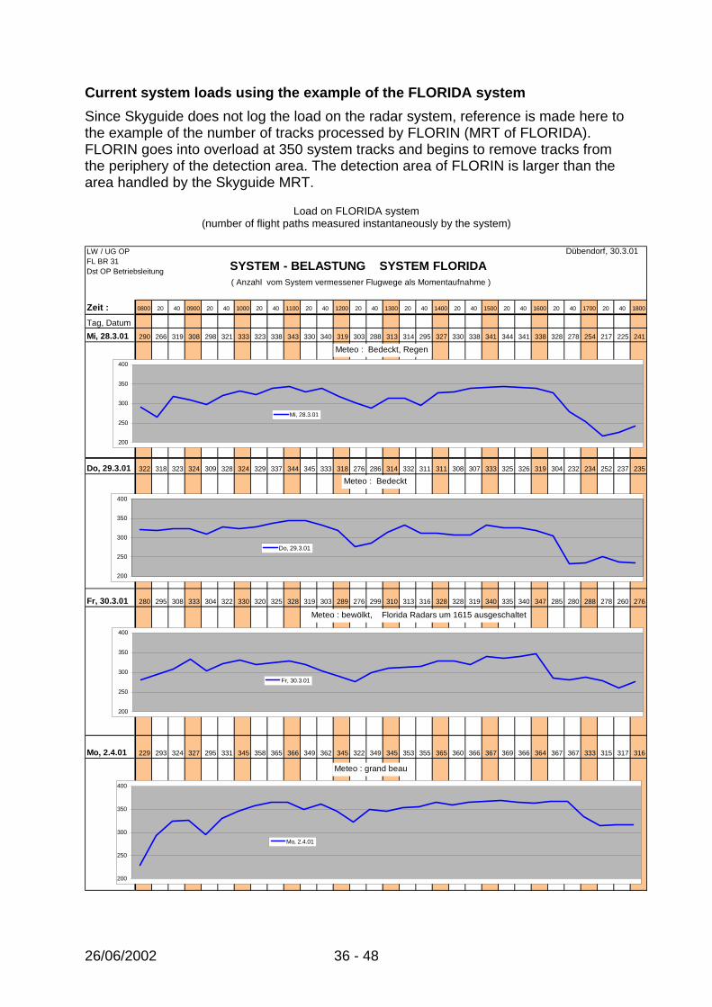
Current system loads using the example of the FLORIDA system Since Skyguide does not log the load on the radar system, reference is made here to the example of the number of tracks processed by FLORIN (MRT of FLORIDA). FLORIN goes into overload at 350 system tracks and begins to remove tracks from the periphery of the detection area. The detection area of FLORIN is larger than the area handled by the Skyguide MRT.
Load on FLORIDA system (number of flight paths measured instantaneously by the system)
LW / UG OP Dübendorf, 30.3.01FL BR 31Dst OP Betriebsleitung
Zeit : 0800 20 40 0900 20 40 1000 20 40 1100 20 40 1200 20 40 1300 20 40 1400 20 40 1500 20 40 1600 20 40 1700 20 40 1800
Tag, DatumMi, 28.3.01 290 266 319 308 298 321 333 323 338 343 330 340 319 303 288 313 314 295 327 330 338 341 344 341 338 328 278 254 217 225 241
Do, 29.3.01 322 318 323 324 309 328 324 329 337 344 345 333 318 276 286 314 332 311 311 308 307 333 325 326 319 304 232 234 252 237 235
Fr, 30.3.01 280 295 308 333 304 322 330 320 325 328 319 303 289 276 299 310 313 316 328 328 319 340 335 340 347 285 280 288 278 260 276
Mo, 2.4.01 229 293 324 327 295 331 345 358 365 366 349 362 345 322 349 345 353 355 365 360 366 367 369 366 364 367 367 333 315 317 316
SYSTEM - BELASTUNG SYSTEM FLORIDA
200
250
300
350
400
Do, 29.3.01
200
250
300
350
400
Mi, 28.3.01
( Anzahl vom System vermessener Flugwege als Momentaufnahme )
200
250
300
350
400
Fr, 30.3.01
Meteo : Bedeckt, Regen
Meteo : Bedeckt
Meteo : bewölkt, Florida Radars um 1615 ausgeschaltet
200
250
300
350
400
Mo, 2.4.01
Meteo : grand beau

26/06/2002 37 - 48
Figure 17: Number of system tracks using the example of FLORIN (FLORIDA MRT). Above 350 system tracks FLORIN limits the load by removing tracks at the periphery of the detection area.
Load distribution is dependent on the position of the air corridors which group air traffic together. The distribution of system tracks recorded for a period of 5 hours on 2 April is shown below.
Figure 18: Sum of all flight tracks recorded by FLORIN on 2 April 2001 between
13:00 and 18:00 hours. 3.2.5 Aircraft without transponders (primary surveillance radar)
Since September 1998, ACC GVA no longer has access to data from a primary surveillance radar (en-route). Aircraft with a defective transponder may no longer be detected by ACC GVA and may not be shown on the display screens. The same applies to aircraft which do not wish to be detected and switch off their transponder. The integration of the military primary surveillance radar is not planned as part of the ATMAS and FLORAKO projects. In the ATMAS project, the use of the common civil-military situation in the air processed by FLORAKO is limited to the implementation of the possibility of representation within a window on the console.

26/06/2002 38 - 48
3.2.6 Airspace without radar coverage
In Switzerland parts of the airspace have no radar coverage, in particular because of the topography. Air traffic which flies into a zone without radar coverage disappears from the ATC screen. 3.3 Analysis
3.3.1 Transponder faults due to microwave transmissions
A fault in the transponder may mean that an interogation from an SSR will no longer be replied. If the MRT receives no data from the SSR more than 3 times, the track is deleted. In order for the track to reappear on the ATC console, it must first be re-initialised by SSR data and established. 3.3.2 Transponders outside the specification
The FAA study is based on an analysis of a wide range of 548 transponders from 12 different manufacturers, predominantly installed in aircraft (General Aviation) for private and commercial aircraft. The transponders were tested using the DATAS test system by the William J. Hughes Technical Centre of the FAA.
Figure 19: Transponder models from different manufacturers tested by the FAA
for compliance with the specification The problems with compliance with the specification highlighted in the FAA study are also relevant to Skyguide. ATCs have found that aircraft, e.g. of the Dornier 328 type equipped with the Honeywell RCZ833 transponder, frequently disappear from the screen.
26/06/2002 39 - 48
Responses which cannot be interpreted may cause the track to be no longer updated, then deleted (by the MRT after 3 unsuccessful updates) and finally re-initialised and reconstituted. 3.3.3 Aircraft from an adjacent ORCAM zone
The limits on correlation of SSR radar data with current flight plan data by the MRT for tracks with ORCAM zone transponder codes for Zurich means that aircraft arriving from an adjacent ORCAM zone will be presented with certainty only if the flight plan data corresponds to the code actually set and the change in flight plan data is synchronised with entry into the Swiss zone. Extending the correlation to the codes in both adjacent ORCAM zones would considerably alleviate the problem of aircraft possibly becoming invisible on transition between the ORCAM zones. 3.3.4 Capacity and overloading of elements of the radar system
The examples of the number of system tracks provided by FLORIN provides an indication of the load on the Skyguide MRT. The area covered by FLORIDA is approx. 50% larger than the area covered by the two Skyguide MRT. Assuming a uniform distribution of the track load, the load on the Skyguide MRT would be 1/3 lower than that on FLORIN. Above 350 tracks, FLORIN limits load by degrading performance from the periphery of the detection area. The limit of 350 tracks is currently exceeded by FLORIN fairly often. In the airspace covered by FLORIN, loads in excess of 450 tracks are common. If one then takes into account the high density of air traffic over Switzerland according to Figure 18, the FLORIN track loads provide clear indications of loads in excess of 3001 tracks in the coverage area of the Skyguide MRT. Reliable quantitative information on loading and track distribution for the individual elements can be recorded and analysed only by Skyguide. 3.3.5 Aircraft without transponders (primary surveillance radar)
ATC duties also require surveillance of controlled airspace with reference to the endangering of controlled aircraft by other aircraft. However, if, as in the case of ACC Geneva there is no primary surveillance radar (en-route), aircraft without transponders or aircraft with a defective transponder or one which has been deliberately switched off are not detected and displayed for the ATC. The task of airspace surveillance could be fulfilled once more by integrating existing or envisaged primary surveillance radars in the preparation of the situation in the air for Skyguide.
1 350 ? ? JM
26/06/2002 40 - 48
3.3.6 Airspace without radar coverage
In the Skyguide radar system, airspace without radar coverage can occur, in addition to geographically defined areas with radar shadows, if the 3 radar stations predefined in MRT for an area fail.
3.4 Summary
Aircraft in the area for which Skyguide is responsible may disappear from or not be displayed on the screen of the ATC responsible for them. Various causes may cause aircraft not to be displayed on the screen:
• Faults in the transponders of aircraft, e.g. because of microwave transmissions in the 1030 MHz frequency range of the SSR.
• Certain transponders have problems with the interogation from the SSR because of parameters which are outside the specification.
• Aircraft arriving from an adjacent ORCAM zone are filtered out under certain circumstances and therefore not displayed.
• If the track load exceeds the capacity limit of elements of the radar system, tracks may be lost in whole or in part (for certain SSR) in an unforeseeable way. No targeted measures exist to reduce the loading below the capacity limit, taking performance bottlenecks into account (e.g. range reduction).
• ACC GVA is working without a primary surveillance radar (en-route). Aircraft without transponders, with defective transponders or with transponders which have been deliberately switched off are not detected or displayed.
Without primary surveillance radar it is possible to perform only the task of controlling cooperative air traffic, but not airspace surveillance. 3.5 Safety recommendations
• In addition to air traffic control (SSR), airspace surveillance must also be ensured by means of a powerful primary surveillance radar (PSR).
• The following aircraft must also be visible in the display of the situation in the air:
o those with transponders subject to interference
o those with a transponder which does not meet the specifications
o those flying from an adjacent ORCAM zone into Swiss airspace
o those with a defective transponder

26/06/2002 41 - 48
o those flying with their transponder switched off.
• The load on subsystems must be regularly monitored, recorded and systematically analysed.
• Alarms which indicate that critical values have been exceeded must be periodically checked.
• Measures must be taken to systematically reduce the system load below the capacity limit.
• Prior to authorisation of an increase in air traffic in Swiss airspace, the ability of existing systems to cope with such an increase must be confirmed.
On the basis of the transponder study, the FAA recommends:
• “The results of this study were the basis for recommending the pursuit of follow-on research initiatives aimed at: (1) the in-depth investigation of operationally significant transponder failures, (2) determining the technical health of transponders carried by commercial aircraft, and (3) identifying the level of transponder and altitude encoder performance that will be needed for safe operations in the future Free Flight environment.
• A further recommendation is made to examine the need for improved methods and procedures to ensure the performance of transponders operating in the NAS. It is recommended that this be accomplished by forming a special committee composed of members drawn from government, industry, and GA user organizations. As a part of its charter, the committee should be tasked to: (1) examine current and future transponder performance requirements for safe NAS operations, (2) evaluate the effectiveness of biennial tests in meeting these requirements, and (3) make recommendations for methods and evaluation procedures that would support a consistently high level of transponder performance in the GA population, and (4) assess any system safety impact with either TCAS or SSR/NAS operations if determined to be a problem and suggest corrective action.”

26/06/2002 42 - 48
4 Legal recording of the situation in the air 4.1 History
The following radar incident on 2 December 1999 was reported to the AAIB by ATC:
“A traffic incident was just avoided between an aircraft flying to Geneva (TAR 700, descent stopped at the last minute) and an aircraft in transit at flight level 240 (RGI 672K) not shown on the ICWS radar of the control sector concerned (KINES). Furthermore, the radar operator for the 6th sector (adjacent physical position) did not see this aircraft on his screen after carrying out the appropriate manipulation. This aircraft was displayed correctly only after the code requested by Geneva was displayed”.
ATC personnel note in their conclusion to the case of 2 December 1999: “This aircraft which was not displayed on the ICWS, was displayed on the
recording of the radar situation”. The following question must be addressed: can the reproduction of the radar tracks by the legal recording differ from the situation in the air as it is displayed to ATCs on their workstations? 4.2 Findings
The following block diagram shows that the legal recording (REC01) records the radar data at the input to the “MRT” (radar sources) and the processed data (ACC and APP tracks) at its output.
Lägern
La Dôle
TG
Cointrin
Nevers
Chaumont
Mte Lesima
X-Clients
REC
REC
REC
REC
REC
REC
REC
REC
REC
Format AIRCAT
WandlerASTERIXAIRCAT
ConvertiseurASTERIXAIRCAT
WandlerASTERIXAIRCAT
LAN ATC
MV 9800
MRT
ACC-Diffusion
Radarquellen :
Verarbeitung
ACC-AnzeigeICWS ICWS
X-Server X-Server
X-Clients
ICWS ICWS
X-Server X-Server
X-Clients
ICWS ICWS
X-Server X-Server
X-Clients
ICWS ICWS
X-Server X-Server
X-Clients
ICWS ICWS
X-Server X-Server
X-Clients
ICWS ICWS
X-Server X-Server
SMP
IPG
REC-Eingänge: Daten Telefon, Funk, usw.
REC 01
S Y M A D e s k
RCMSA D A P T

26/06/2002 43 - 48
The possible errors or losses caused by the ADAPT system, as well as the influence of the settings at the individual workstation (ICWS, screens) are ignored by the legal recording.
The Eurocontrol standard document contains the following statement on the legal recording:
“The recording medium and mechanism should be such that a complete reconstruction of the surveillance data presentation, display settings and selections can be produced at the controller’s display position.”
The following statement is contained in the record of the 19th ATCOM session:
“The source used for the investigation is based on a mono-radar distance. The controller uses a certain processed picture, which is not always identical to the picture printed with the ATL evaluation software. ... In a further step (REC02), the set-up of the working places, the various inputs into the working stations, the positioning of the windows will be included in the recording”
Expansion stage REC02 of the legal recording has not been implemented to date. Skyguide wrote in its answer dated 8.9.1998 to the interim recommendation of the AAIB with regard to the near-collision SWR3779/CRX985 of 15 June 1998 (Figure 3):
“Naturally, the question remains as to the reliability of radar recordings in the case of an investigation. I think I can state in this regard that mono-radar recordings provide sufficient accuracy and coherence to be able to establish the facts in the event of an incident.” 4.3 Analysis
For the investigation of incidents or accidents, Skyguide proposes the use of a single radar source (SSR) instead of the MRT, since the coherence and accuracy of a single radar source are deemed to be better. ATC, however, works with the MRT data as a basis for its decisions. These are also recorded by the legal recording, but not in the form in which they are presented to the ATC. In particular, the presentation software is affected by the history of the actions and procedures since the workstation was booted up. In view of the complexity of the software, replaying the data must be deemed inadequate for obtaining reliable information on the situation in the air which is actually presented. This seriously affects the reliability of any investigation into a serious incident or accident.
4.4 Summary
The recording of radar data at the MRT input and output is not adequate for a full reconstruction of the situation in the air as presented to the responsible ATC at the console. This “legal recording” may differ from the presentation on the console.
26/06/2002 44 - 48
4.5 Safety recommendations
The legal recording must be adapted to the Eurocontrol recommendation so that a complete reconstruction is possible at the level of the ATC console. In particular, it must be possible to reproduce the presentation of the situation in the air, screen settings and console settings. Berne, 26 June 2002 Aircraft Accident Investigation Bureau

26/06/2002 45 - 48
5 Glossary ACC Area Control Centre ADAPT Air Traffic Management Data Acquisition Processing and Transfer Name of the project started by Skyguide in the early ‘nineties to replace the
Swiss civil air traffic control system with workstations incorporating the totality of technical functions.
AIRCAT Concept used by Thomson-CSF (now "Thales ATM") for modem transfer of
data from radar sources. AIRPROX AIRcraft PROXimity Near-collision of two aircraft. AGNES (Automated GPS NEtwork for Switzerland) APP APProach Control Office ATC Air Traffic Control / Air Traffic Controller
ATCAR Air Traffic Control Areas of Responsibility Includes “en-route” and” Approach” ATCOM Air Traffic COMmission ATIR Air Traffic Incident Report AAIB Aircraft Accident Investigation Bureau DGPS Differential Global Positioning System. GPS receiver whose position error is reduced with the aid of a difference
between its actual and measured position using a reference station. EATCHIP European Air Traffic Control Harmonisation and Integration Programme. This programme is now called EATMP.

26/06/2002 46 - 48
EATMP European Air Traffic Management Programme FAA Federal Aviation Administration FLORIDA Military airspace surveillance and control system for Switzerland FLORIN FLORIDA INtegration FLORIDA MRT GPS Global Positioning System Global satellite navigation system. GVA GeneVA Acronym used to designate Geneva airport. ICAO International Civil Aviation Organisation. ICWS Integrated Controller WorkStation Workstation equipped with a large colour screen to display the radar situation
for the ATC. IPG IPS Processor Gateway Workstation providing the link between the MV9800 computers and the
ADAPT System. IPS Indicateur Panoramique Synthétique. Synthetic panoramic indicator. LAN Local Area Network Local network which allows IT systems to be linked together. MRT MultiRadar Tracker Multiradar tracking system. NM Nautical Mile Unit of measurement of length, corresponds to 1852 metres. ORCAM Originating Region Code Assignment Methodology

26/06/2002 47 - 48
PG Plot Generator Format used by Thomson-CSF (now "Thales ATM") to disseminate MRT
information. PSR Primary Surveillance Radar. Classic primary radar, as opposed to secondary surveillance radar. REC01 RECording system phase 01 Recording and reproduction system for radar data and communications (radio
and telephone). RCMS Remote Control and Monitoring System PCs used for control and monitoring of the MV9800 computers. RMS error Root Mean Square error Used to qualify the absolute accuracy of a physical measurement. SMP System Management and Control Processor Workstation which is used to manage and control all the ADAPT equipment. SSR Secondary Surveillance Radar Radar system which uses an active target, i.e. one which is equipped with a
transmitter- receiver which transmits encoded useful information (identification and pressure altitude).
SYMA SYstem Management Technical position in the control room, where all the terminals or management
and monitoring consoles of the major technical systems are installed. TCAS Traffic Alert and Collision Avoidance System Track Flight path, calculated from the position measurements of the radar stations in
a 2D or 3D system of coordinates. UTC Universal Time Coordinated Previously known as GMT.

26/06/2002 48 - 48
X-Client X Window Client X Client: user program which, by means of a protocol, uses the services of an
X server by submitting to it requests for display or dialogue with the user. X-Server X Window Server X Server: program which ensures management and control of I/O peripherals
(screen, keyboard and mouse) of an X Window workstation. X Window Window-based technology founded on the client/server model and working in a
distributed manner on a local area network. ZRH ZuRicH Acronym used to designate Zurich airport.