Embed Size (px)
Citation preview

• Radar Nomenclature• Radar Logic• Synthetic Aperture Radar• Radar Relief Displacement• Return Exams
• Next Class: Read Chapter 10
Active Remote Sensing Systems

Radar Nomenclature
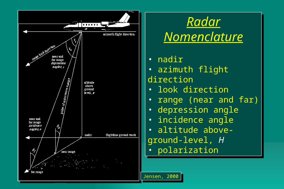
• nadir• azimuth flight direction• look direction• range (near and far)• depression angle• incidence angle • altitude above-ground-level, H• polarization
Radar Nomenclature
• nadir• azimuth flight direction• look direction• range (near and far)• depression angle• incidence angle • altitude above-ground-level, H• polarization
Jensen, 2000Jensen, 2000
RADARlogic
RADARlogic
Jensen, 2000Jensen, 2000
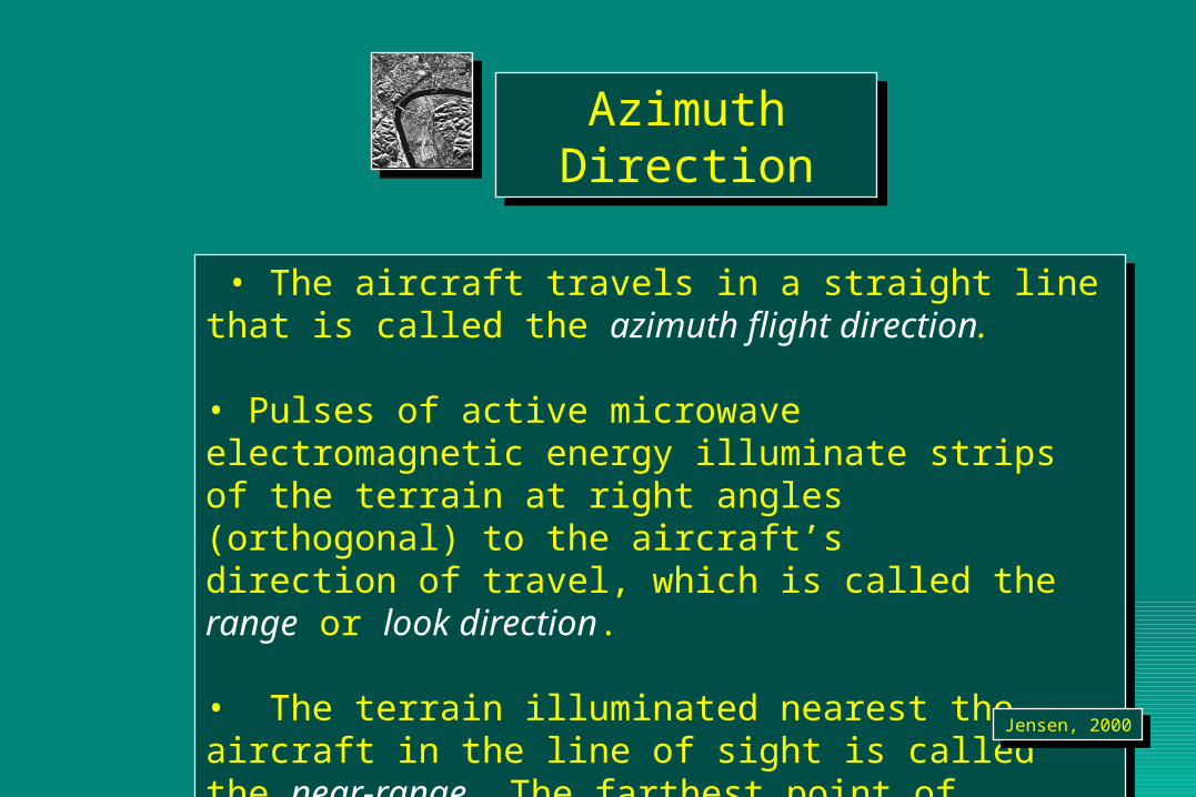
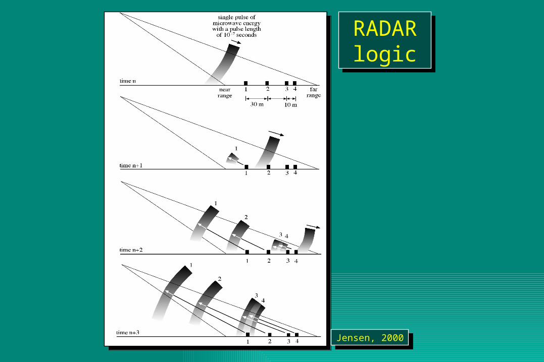
• The aircraft travels in a straight line that is called the azimuth flight direction.
• Pulses of active microwave electromagnetic energy illuminate strips of the terrain at right angles (orthogonal) to the aircraft’s direction of travel, which is called the range or look direction.
• The terrain illuminated nearest the aircraft in the line of sight is called the near-range. The farthest point of terrain illuminated by the pulse of energy is called the far-range.
Jensen, 2000Jensen, 2000
Azimuth DirectionAzimuth Direction
Radar Nomenclature
• nadir• azimuth flight direction• look direction• range (near and far)• depression angle• incidence angle• altitude above-ground-level, H• polarization
Radar Nomenclature
• nadir• azimuth flight direction• look direction• range (near and far)• depression angle• incidence angle• altitude above-ground-level, H• polarization
Jensen, 2000Jensen, 2000
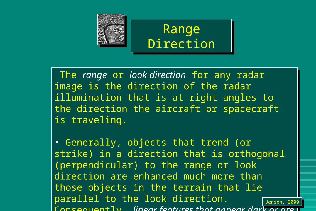
The range or look direction for any radar image is the direction of the radar illumination that is at right angles to the direction the aircraft or spacecraft is traveling.
• Generally, objects that trend (or strike) in a direction that is orthogonal (perpendicular) to the range or look direction are enhanced much more than those objects in the terrain that lie parallel to the look direction. Consequently, linear features that appear dark or are imperceptible in a radar image using one look direction may appear bright in another radar image with a different look direction.
Jensen, 2000Jensen, 2000
Range DirectionRange Direction
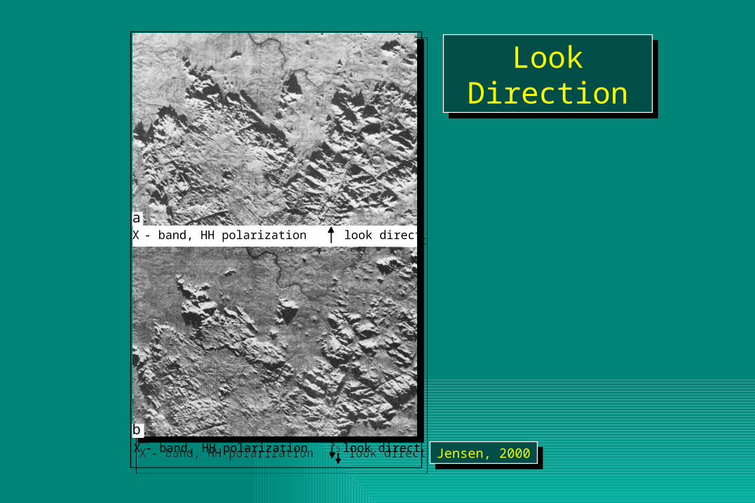
Look DirectionLook Direction
a.
b.look direction
X - band, HH polarization look direction
sX - band, HH polarization
a.
b.look direction
X - band, HH polarization look direction
sX - band, HH polarizationJensen, 2000Jensen, 2000
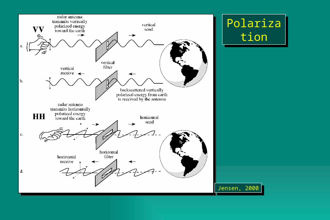
Unpolarized energy vibrates in all possible directions perpendicular to the direction of travel.
• Radar antennas send and receive polarized energy. This means that the pulse of energy is filtered so that its electrical wave vibrations are only in a single plane that is perpendicular to the direction of travel. The pulse of electromagnetic energy sent out by the antenna may be vertically or horizontally polarized.
Jensen, 2000Jensen, 2000
PolarizationPolarization
PolarizationPolarization
Jensen, 2000Jensen, 2000
RADAR ResolutionRADAR Resolution
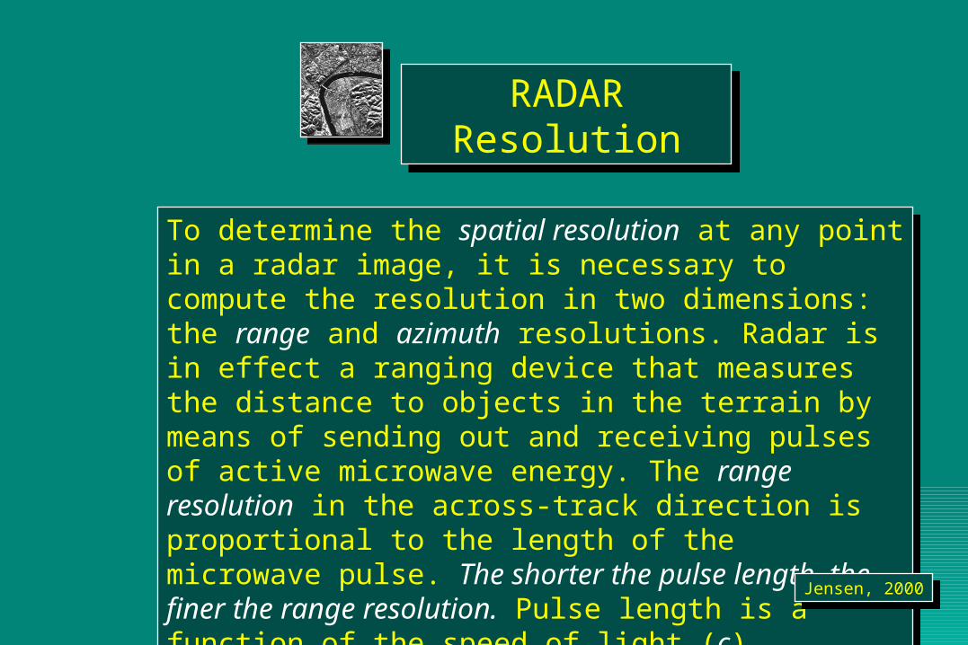
To determine the spatial resolution at any point in a radar image, it is necessary to compute the resolution in two dimensions: the range and azimuth resolutions. Radar is in effect a ranging device that measures the distance to objects in the terrain by means of sending out and receiving pulses of active microwave energy. The range resolution in the across-track direction is proportional to the length of the microwave pulse. The shorter the pulse length, the finer the range resolution. Pulse length is a function of the speed of light (c) multiplied by the duration of the transmission (t).
To determine the spatial resolution at any point in a radar image, it is necessary to compute the resolution in two dimensions: the range and azimuth resolutions. Radar is in effect a ranging device that measures the distance to objects in the terrain by means of sending out and receiving pulses of active microwave energy. The range resolution in the across-track direction is proportional to the length of the microwave pulse. The shorter the pulse length, the finer the range resolution. Pulse length is a function of the speed of light (c) multiplied by the duration of the transmission (t).
Jensen, 2000Jensen, 2000
RADAR Relief Displacement, Image Foreshortening, and Shadowing
RADAR Relief Displacement, Image Foreshortening, and Shadowing
Geometric distortions exist in almost all radar imagery, including :
• foreshortening,
• layover, and
• shadowing.
Geometric distortions exist in almost all radar imagery, including :
• foreshortening,
• layover, and
• shadowing.
Jensen, 2000Jensen, 2000

Forshortening, Layover, and
Shadow
Forshortening, Layover, and
Shadow
Jensen, 2000Jensen, 2000
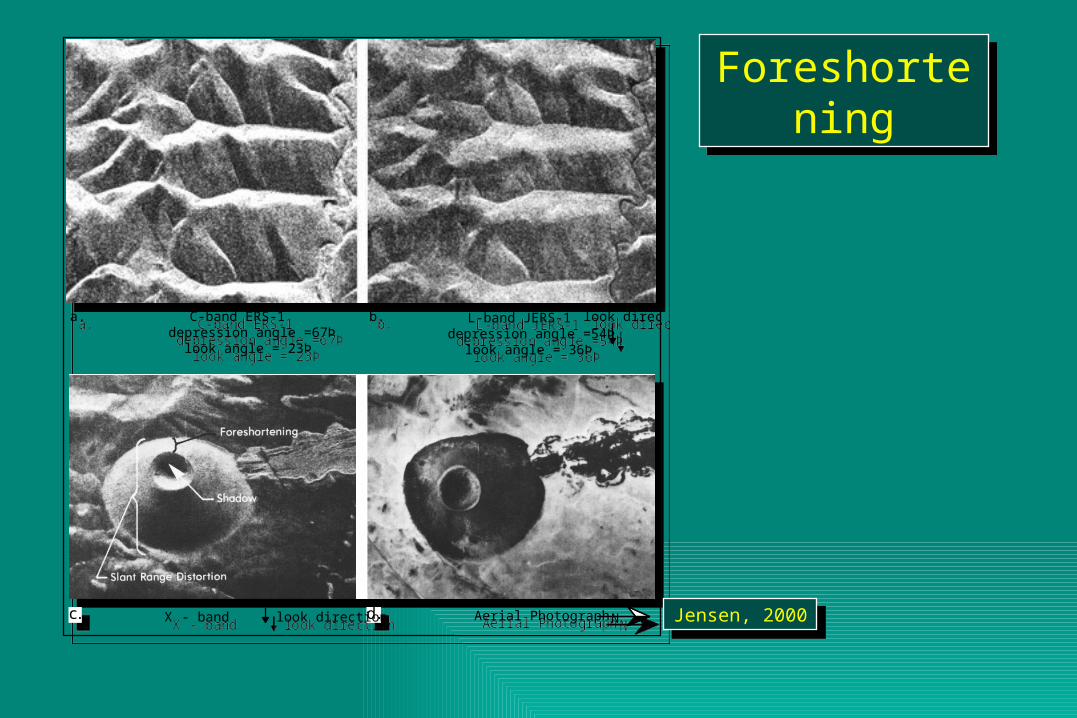
ForeshorteningForeshortening
a. b.C-band ERS-1 depression angle =67Þ
look angle = 23Þ
L-band JERS-1 depression angle =54Þ
look angle = 36Þ
look direction
c. d.X - band Aerial Photographlook direction N
a. b.C-band ERS-1 depression angle =67Þ
look angle = 23Þ
L-band JERS-1 depression angle =54Þ
look angle = 36Þ
look direction
c. d.X - band Aerial Photographlook direction N Jensen, 2000Jensen, 2000
RADAR ShadowsRADAR Shadows
Shadows in radar images can enhance the geomorphology and texture of the terrain. Shadows can also obscure the most important features in a radar image, such as the information behind tall buildings or land use in deep valleys. If certain conditions are met, any feature protruding above the local datum can cause the incident pulse of microwave energy to reflect all of its energy on the foreslope of the object and produce a black shadow for the backslope.
Shadows in radar images can enhance the geomorphology and texture of the terrain. Shadows can also obscure the most important features in a radar image, such as the information behind tall buildings or land use in deep valleys. If certain conditions are met, any feature protruding above the local datum can cause the incident pulse of microwave energy to reflect all of its energy on the foreslope of the object and produce a black shadow for the backslope.
Jensen, 2000Jensen, 2000
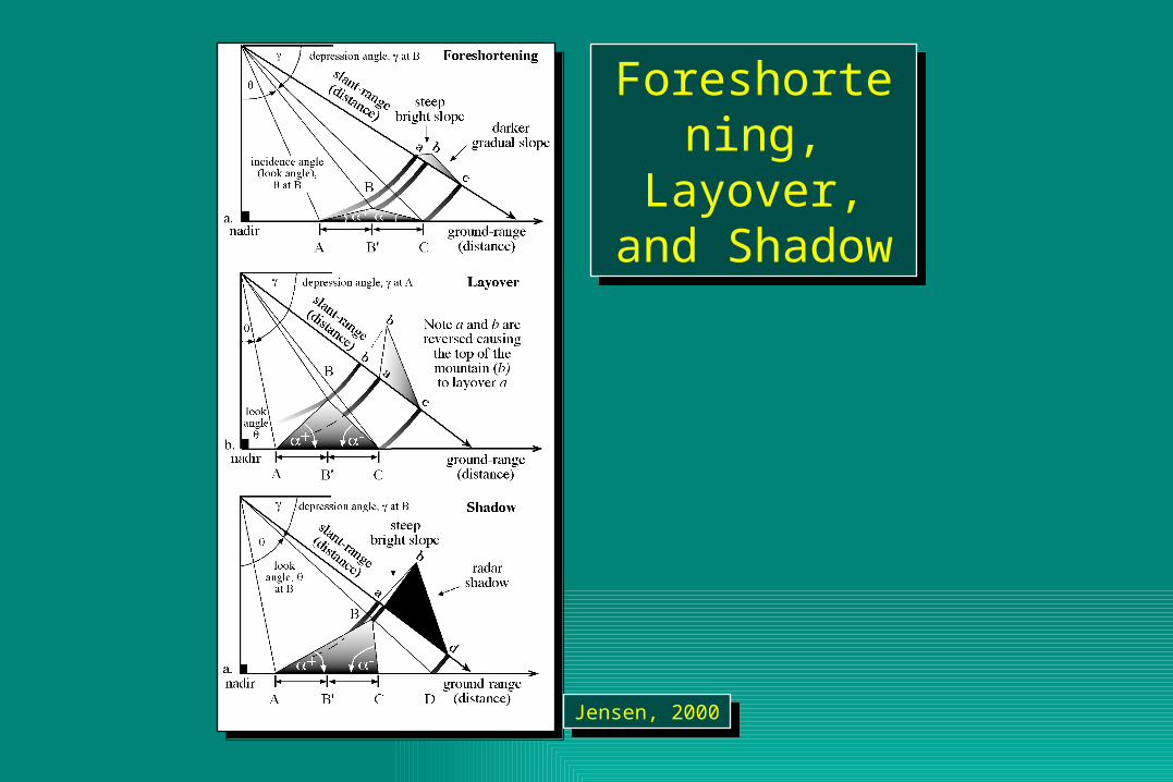
Foreshortening, Layover, and
Shadow
Foreshortening, Layover, and
Shadow
Jensen, 2000Jensen, 2000
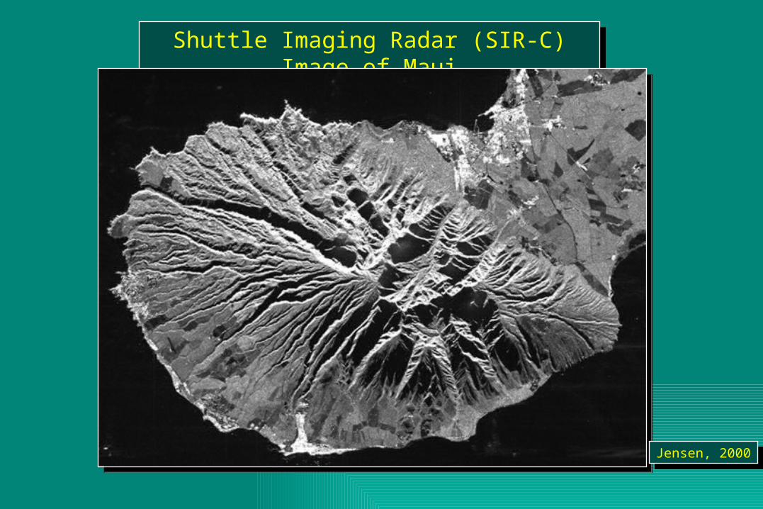
Shuttle Imaging Radar (SIR-C) Image of MauiShuttle Imaging Radar (SIR-C) Image of Maui
Jensen, 2000Jensen, 2000
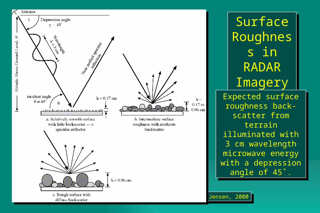
Surface Roughness in RADAR Imagery
Surface Roughness in RADAR Imagery
Expected surface roughness back-scatter from terrain illuminated with 3 cm wavelength
microwave energy with a depression angle of 45˚.
Expected surface roughness back-scatter from terrain illuminated with 3 cm wavelength
microwave energy with a depression angle of 45˚.
Jensen, 2000Jensen, 2000
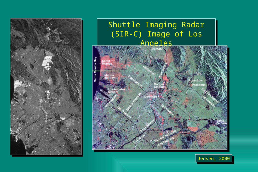
Shuttle Imaging Radar (SIR-C) Image of Los Angeles
Shuttle Imaging Radar (SIR-C) Image of Los Angeles
Jensen, 2000Jensen, 2000
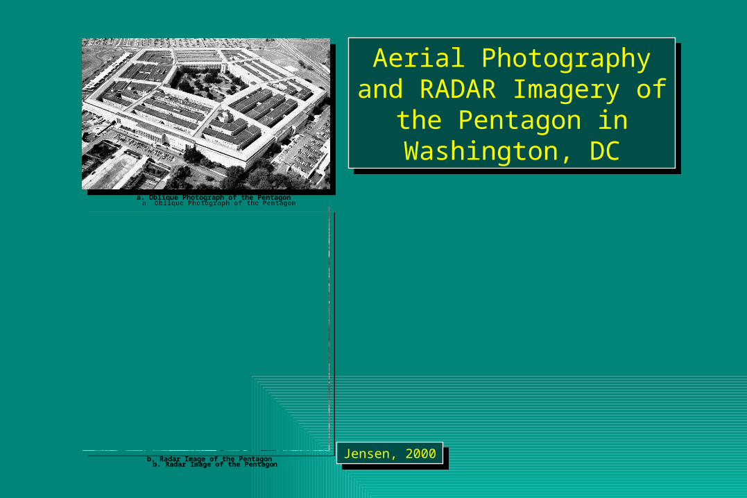
Aerial Photography and RADAR Imagery of the
Pentagon in Washington, DC
Aerial Photography and RADAR Imagery of the
Pentagon in Washington, DC
Jensen, 2000Jensen, 2000
a. Oblique Photograph of the Pentagon
b. Radar Image of the Pentagon
a. Oblique Photograph of the Pentagon
b. Radar Image of the Pentagon
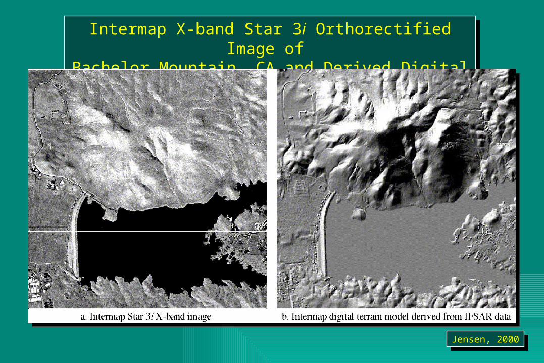
Intermap X-band Star 3i Orthorectified Image of Bachelor Mountain, CA and Derived Digital Elevation Model
Intermap X-band Star 3i Orthorectified Image of Bachelor Mountain, CA and Derived Digital Elevation Model
Jensen, 2000Jensen, 2000
Synthetic Aperture Radar SystemsSynthetic Aperture Radar Systems
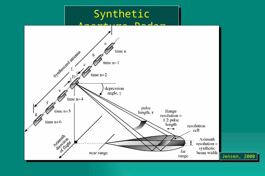
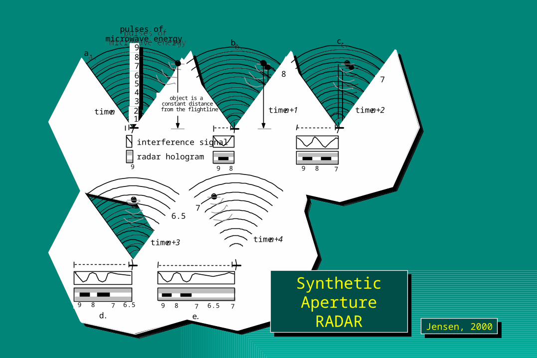
A major advance in radar remote sensing has been the improvement in azimuth resolution through the development of synthetic aperture radar (SAR) systems. Remember, in a real aperture radar system that the size of the antenna (L) is inversely proportional to the size of the angular beam width. Great improvement in azimuth resolution could be realized if a longer antenna were used. Engineers have developed procedures to synthesize a very long antenna electronically. Like a brute force or real aperture radar, a synthetic aperture radar also uses a relatively small antenna (e.g., 1 m) that sends out a relatively broad beam perpendicular to the aircraft. The major difference is that a greater number of additional beams are sent toward the object. Doppler principles are then used to monitor the returns from all these additional microwave pulses to synthesize the azimuth resolution to become one very narrow beam.
A major advance in radar remote sensing has been the improvement in azimuth resolution through the development of synthetic aperture radar (SAR) systems. Remember, in a real aperture radar system that the size of the antenna (L) is inversely proportional to the size of the angular beam width. Great improvement in azimuth resolution could be realized if a longer antenna were used. Engineers have developed procedures to synthesize a very long antenna electronically. Like a brute force or real aperture radar, a synthetic aperture radar also uses a relatively small antenna (e.g., 1 m) that sends out a relatively broad beam perpendicular to the aircraft. The major difference is that a greater number of additional beams are sent toward the object. Doppler principles are then used to monitor the returns from all these additional microwave pulses to synthesize the azimuth resolution to become one very narrow beam.
Jensen, 2000Jensen, 2000
Synthetic Aperture Radar SystemsSynthetic Aperture Radar Systems
The Doppler principle states that the frequency (pitch) of a sound changes if the listener and/or source are in motion relative to one another.
• An approaching train whistle will have an increasingly higher frequency pitch as it approaches. This pitch will be highest when it is directly perpendicular to the listener (receiver). This is called the point of zero Doppler. As the train passes by, its pitch will decrease in frequency in proportion to the distance it is from the listener (receiver). This principle is applicable to all harmonic wave motion, including the microwaves used in radar systems.
Jensen, 2000Jensen, 2000
Synthetic Aperture RadarSynthetic Aperture Radar
Jensen, 2000Jensen, 2000
Jensen, 2000Jensen, 2000
9 8 7 6 5 4 3 2 1
time n
time n+4time n+3
time n+2
pulses of microwave energy
interference signal
radar hologram
a.b. c.
d. e.
8 7
6.5 7
9 9 8 9 8 7
78 9 78 9 6.5 6.5 7
time n+1
object is a constant distance from the flightline
9 8 7 6 5 4 3 2 1
time n
time n+4time n+3
time n+2
pulses of microwave energy
interference signal
radar hologram
a.b. c.
d. e.
8 7
6.5 7
9 9 8 9 8 7
78 9 78 9 6.5 6.5 7
time n+1
object is a constant distance from the flightline
Synthetic ApertureRADAR
Synthetic ApertureRADAR
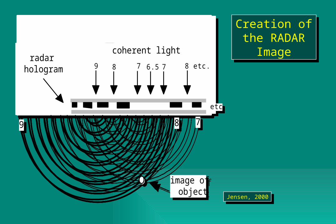
Creation of the RADAR Image
Creation of the RADAR Image
Jensen, 2000Jensen, 2000
coherent lightradar
hologram
image of object
9 8 7
9 8 7 6.5 7 8 etc.
etc.
coherent lightradar
hologram
image of object
9 8 7
9 8 7 6.5 7 8 etc.
etc.