Embed Size (px)
Citation preview
8/4/2019 Final Report on ARM
http://slidepdf.com/reader/full/final-report-on-arm 1/21
Robot
Arm
Final Report
Cao Yanxin; Cao Zhen;Liu Xiaowei; Dominggus
Yosua Suitella; Johanvan Mijl
8/4/2019 Final Report on ARM
http://slidepdf.com/reader/full/final-report-on-arm 2/21
ContentContent .......................................................................................................................... 2Chapter 1: Introduction .................................................................................................. 3
Background .............................................................................................................. 3Project description ................................................................................................... 3
Chapter 2: Design Phase ................................................................................................ 4Design of the arm .................................................................................................... 4
Original design ................................................................................................. 5Improvements design ........................................................................................ 5
Design of the Basement ......................................................................................... 7Basement Design One ....................................................................................... 7Basement Design two ....................................................................................... 8Basement Design three ..................................................................................... 9
Chapter 3: Calculation ................................................................................................. 11Chapter 4: Program phase ........................................................................................... 13Chapter 5: Final Product ............................................................................................... 16Chapter 6: Conclusion .................................................................................................. 20
Project conclusion .................................................................................................. 20 Technic conclusion ................................................................................................. 20Group conclusion ................................................................................................... 21
8/4/2019 Final Report on ARM
http://slidepdf.com/reader/full/final-report-on-arm 3/21
Chapter 1: Introduction
Background
As for the Fontys project, the team was allotted a project from Department of Mechatronics to design a robot arm for domestic applications, for instance picking upa cup or a book, opening a door. And the robot arm can be mounted on a platform.
The team consists of five members, and all from different backgrounds. A shortoverview below;Name of teamMember
Specialization Task
Johan van Meijl Applied Physics Team leader
Cao 'Cecillia' Yanxin Mechatronics Presentation
Cao 'Tiffany' Zhen Mechatronics Presentation
Yosua Suitella PowerEngineering
Administrator
Liu 'Leo' Xiao Wei ElectricalAutomation
Keeper of theminutes
A tutor, Antoon Pepping and a consultant, Nick van der Sanden, are assigned to theteam to design and solve the problems.
Project description
The project that the team got is to design and build a robot arm for domesticapplications. This robot arm should meet specifications given by the departmentconcerning lifting capacity and size. To meet the requirements, the robot has to beable to pick an object at a distance of half a meter, weighing about half a kilogram.Furthermore it is required to be operated on battery power, should be mountable ona small platform and have a minimum of three degrees of freedom. In the end, therobot arm has to be controlled by, for instance, a joystick, using the parallax propellercontrol board.
The project starts in September of 2010 and should be completed at the beginning of February of 2011. During this period, the project can be divided into following parts:
General plan of the project The project goes through around 18 weeks. It starts with making a general plan aboutwhat should be done in these weeks, and the project is carried out by following theplan.
Robot structure research and selection The first several weeks, the group works on researching the robot arm on the internetto get ideas how to get start. Sketches, drawings in inventor are made by everymember. The group chooses a final design by combining the advantages of eachdesign.
Searching and ordering components for the designAfter determining the final design, the group begins to search for the components, for

8/4/2019 Final Report on ARM
http://slidepdf.com/reader/full/final-report-on-arm 4/21
instance, motors and pulleys, which should meet the requirements. Aluminum ischosen to make the robot arm, because it is light and strong.
Building the designIn the last few weeks, robot arm begins to be mounted, which includes makingcomponents for robot arm, cutting aluminum sheets, drilling holes, installing pulley
system, and etc. The final design should be working properly and, of course, meetthe demands. The group also needs to implement systems and test the robot.
Improvement The group will make some improvements on the robot, for instance applying springon the robot to balance the force, if time is available.
The planning chart shows below
Chapter 2: Design Phase
Design of the arm
We did some researches and found the popular use of robot arm is welding andtransport. Then we got the general idea of design a robot arm.
8/4/2019 Final Report on ARM
http://slidepdf.com/reader/full/final-report-on-arm 5/21
Original design
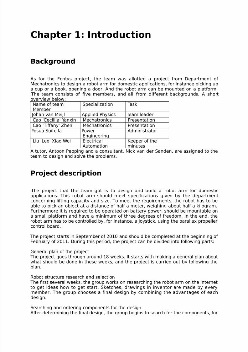
This design has 6 freedoms as shown in the picture. This is the first idea of the robotarm; the following improved designs are all follow is general idea.
Axis 1 connect to the base it can rotate the whole up part. Axis 2 and 3 can do upand down part. Axis 4 and 6 can rotate 360°, and Axis 5 can do up and down work atthe same time. This design makes sure the robot arm reach every position around it.
After creating the model in design software, the axis 4 was considered useless andtherefore deleted.
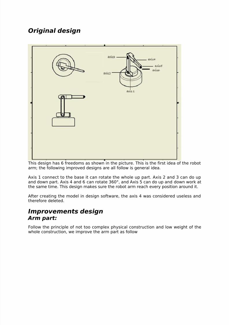
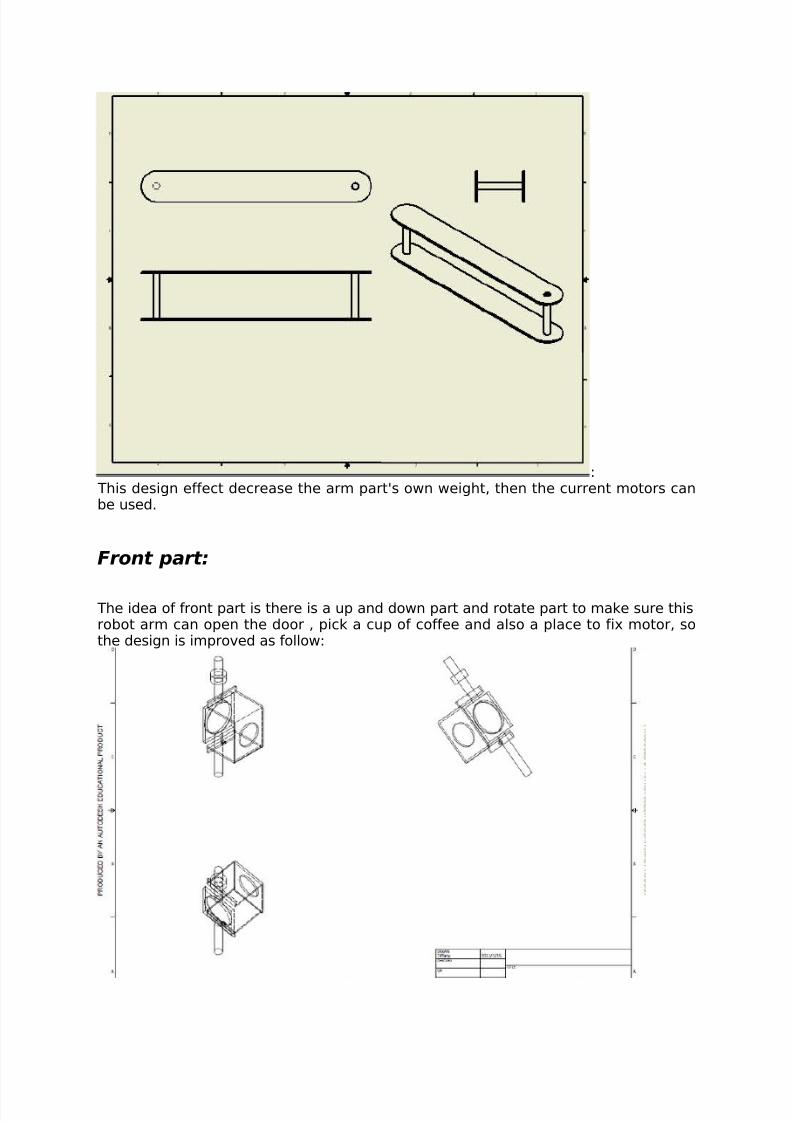
Improvements design Arm part:
Follow the principle of not too complex physical construction and low weight of thewhole construction, we improve the arm part as follow
8/4/2019 Final Report on ARM
http://slidepdf.com/reader/full/final-report-on-arm 6/21
8/4/2019 Final Report on ARM
http://slidepdf.com/reader/full/final-report-on-arm 7/21
The position to put motors:
Where to put the motors is a difficult decision. One suggestion was to put all motorsin the arm, but that would increase the weight of the parts to lift, resulting in the useof stronger motors. This idea was discarded.
Then the better idea came out, using two towers on the foundation to fix two heavemotor. This way we just need fix one heave motor on the robot arm, and one lightone on the front part.
The exactly position refer to the final design.
Design of the Basement
Brief introduction:For the basement design, there are three concepts totally.
For the final concept, there are three options of motors.
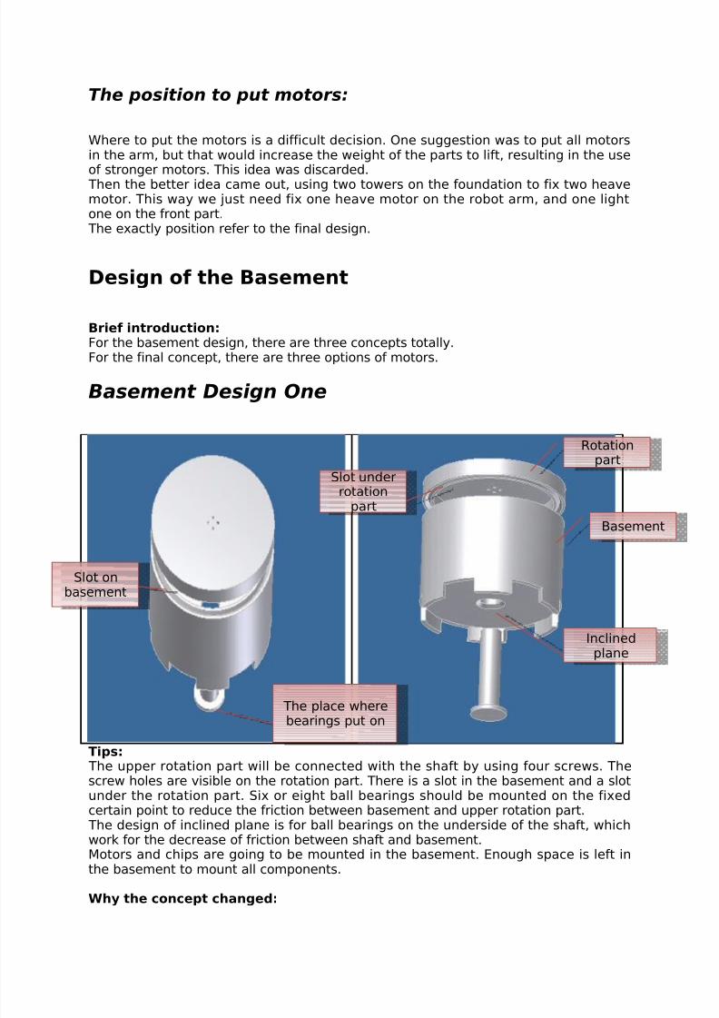
Basement Design One
Tips: The upper rotation part will be connected with the shaft by using four screws. Thescrew holes are visible on the rotation part. There is a slot in the basement and a slotunder the rotation part. Six or eight ball bearings should be mounted on the fixedcertain point to reduce the friction between basement and upper rotation part.
The design of inclined plane is for ball bearings on the underside of the shaft, whichwork for the decrease of friction between shaft and basement.Motors and chips are going to be mounted in the basement. Enough space is left inthe basement to mount all components.
Why the concept changed:
Rotationpart
Basement
Slot onbasement
Slot underrotation
part
Inclinedplane
The place wherebearings put on
8/4/2019 Final Report on ARM
http://slidepdf.com/reader/full/final-report-on-arm 8/21
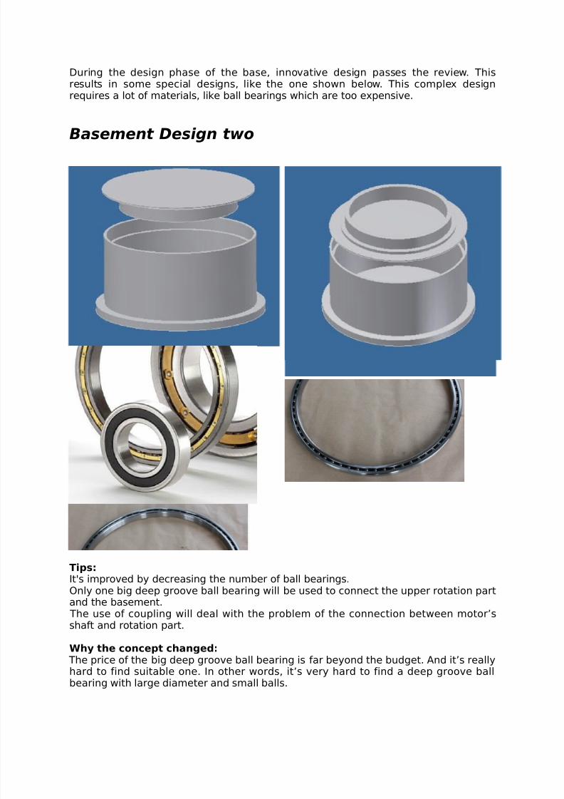
During the design phase of the base, innovative design passes the review. Thisresults in some special designs, like the one shown below. This complex designrequires a lot of materials, like ball bearings which are too expensive.
Basement Design two
Tips:It's improved by decreasing the number of ball bearings.Only one big deep groove ball bearing will be used to connect the upper rotation partand the basement.
The use of coupling will deal with the problem of the connection between motor’sshaft and rotation part.
Why the concept changed: The price of the big deep groove ball bearing is far beyond the budget. And it’s reallyhard to find suitable one. In other words, it’s very hard to find a deep groove ballbearing with large diameter and small balls.
8/4/2019 Final Report on ARM
http://slidepdf.com/reader/full/final-report-on-arm 9/21
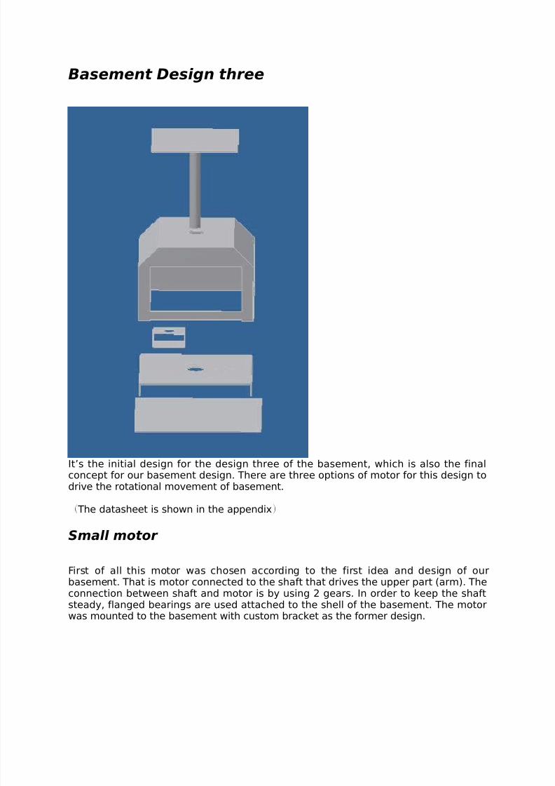
Basement Design three
It’s the initial design for the design three of the basement, which is also the finalconcept for our basement design. There are three options of motor for this design todrive the rotational movement of basement.
( The datasheet is shown in the appendix)
Small motor
First of all this motor was chosen according to the first idea and design of ourbasement. That is motor connected to the shaft that drives the upper part (arm). Theconnection between shaft and motor is by using 2 gears. In order to keep the shaftsteady, flanged bearings are used attached to the shell of the basement. The motorwas mounted to the basement with custom bracket as the former design.
8/4/2019 Final Report on ARM
http://slidepdf.com/reader/full/final-report-on-arm 10/21
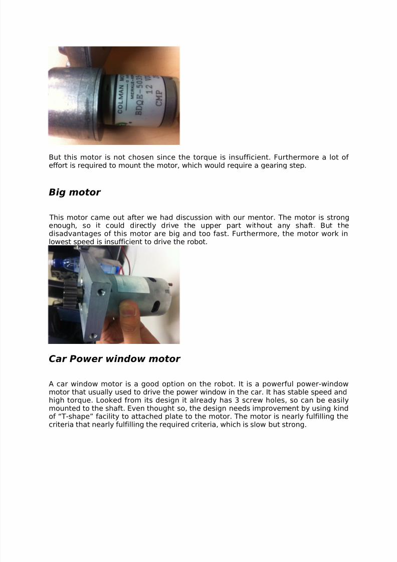
But this motor is not chosen since the torque is insufficient. Furthermore a lot of effort is required to mount the motor, which would require a gearing step.
Big motor
This motor came out after we had discussion with our mentor. The motor is strongenough, so it could directly drive the upper part without any shaft. But thedisadvantages of this motor are big and too fast. Furthermore, the motor work inlowest speed is insufficient to drive the robot.
Car Power window motor
A car window motor is a good option on the robot. It is a powerful power-window
motor that usually used to drive the power window in the car. It has stable speed andhigh torque. Looked from its design it already has 3 screw holes, so can be easilymounted to the shaft. Even thought so, the design needs improvement by using kindof “T-shape” facility to attached plate to the motor. The motor is nearly fulfilling thecriteria that nearly fulfilling the required criteria, which is slow but strong.

8/4/2019 Final Report on ARM
http://slidepdf.com/reader/full/final-report-on-arm 11/21
Finally, the basement design was chosen according to the chosen motors and workedout. The results are the schematically drawings, which will be shown in the appendix.
These were used later on during the production process.
Chapter 3: Calculation
Calculations of torque and moment of inertia
Theory
Torque is the representation of the force required to rotate a mass around an axis.
8/4/2019 Final Report on ARM
http://slidepdf.com/reader/full/final-report-on-arm 12/21
The torque is given in formula by:
=r × F ,in which r is the distance from the axis and F the force on that point.
The formula is angle dependent, which means that the angle between the distancevector and the force vector is proportional to the total torque.
Therefore the equation can also be written as:=rFsin ,
with the angle between the vectors.
In the calculations the assumed point of calculating is the centre of gravity of eachobject, with the robot arm completely stretched. This results in a maximum torque forall joints with the distance and force perpendicular.
The inertia is only relevant for the parts that rotate in the plane parallel to the axis of the motor. In the robot arms case the lowest motor for the base and the first motorfor the wrist have an inertia calculation.
The moment of inertia is defined as the summation of all mass elements multiplied
by the square of their distance to the rotation axis. In formula form this gives:
I =∑mi Ri
2
,with m the mass and R the distance from the rotation axis.
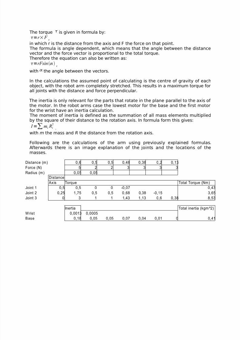
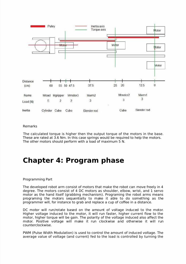
Following are the calculations of the arm using previously explained formulas.Afterwards there is an image explanation of the joints and the locations of themasses.
Distance (m) 0,6 0,5 0,5 0,48 0,38 0,2 0,13
Force (N) 5 2 2 3 3 3 3
Radius (m) 0,05 0,05
DistanceAxis Torque Total Torque (Nm)
Joint 1 0,5 0,5 0 0 -0,07 0,43
Joint 2 0,25 1,75 0,5 0,5 0,68 0,38 -0,15 3,65
Joint 3 0 3 1 1 1,43 1,13 0,6 0,38 8,53
Inertia Total inertia (kgm^2)
W ris t 0,0013 0,0005
Base 0,18 0,05 0,05 0,07 0,04 0,01 0 0,41
8/4/2019 Final Report on ARM
http://slidepdf.com/reader/full/final-report-on-arm 13/21
Remarks
The calculated torque is higher then the output torque of the motors in the base.
These are rated at 3.6 Nm. In this case springs would be required to help the motors. The other motors should perform with a load of maximum 5 N.
Chapter 4: Program phase
Programming Part
The developed robot arm consist of motors that make the robot can move freely in 4degree. The motors consist of 4 DC motors as shoulder, elbow, wrist, and 1 servomotor as the hand itself (grabbing mechanism). Programing the robot arms meansprograming the motors sequentially to make it able to do something as theprogrammer will, for instance to grab and replace a cup of coffee in a distance.
DC motor will run/rotate based on the amount of voltage induced to the motor.Higher voltage induced to the motor, it will run faster, higher current flow to themotor, higher torque will be gain. The polarity of the voltage induced also affect themotor. Positive voltage will make it run clockwise and otherwise it will runcounterclockwise.
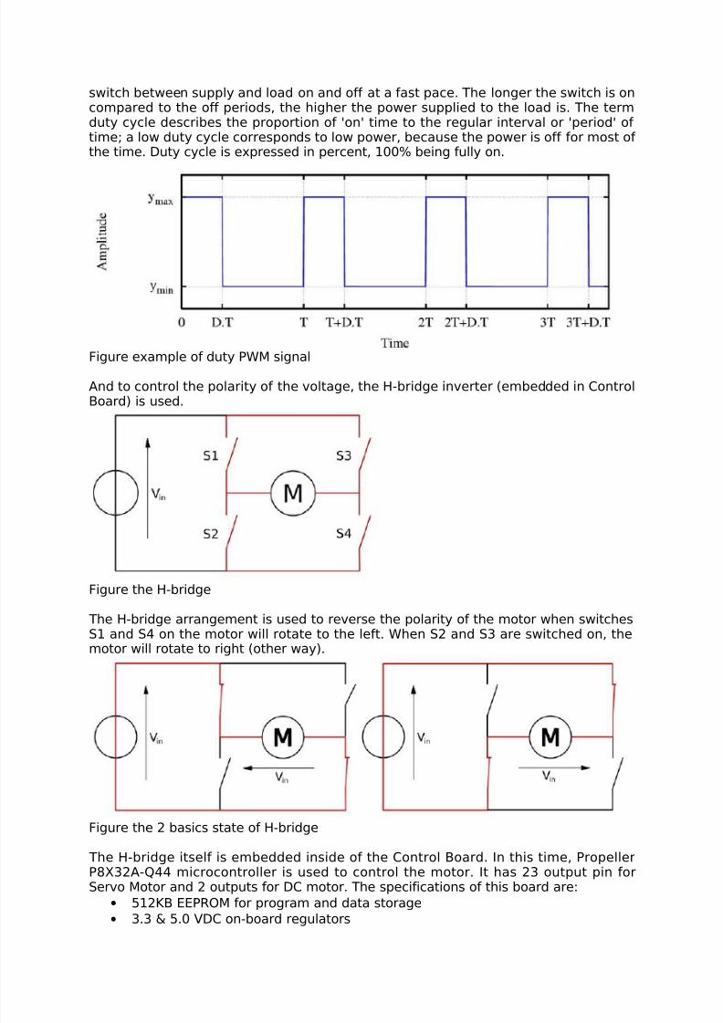
PWM (Pulse Width Modulation) is used to control the amount of induced voltage. Theaverage value of voltage (and current) fed to the load is controlled by turning the
8/4/2019 Final Report on ARM
http://slidepdf.com/reader/full/final-report-on-arm 14/21
switch between supply and load on and off at a fast pace. The longer the switch is oncompared to the off periods, the higher the power supplied to the load is. The termduty cycle describes the proportion of 'on' time to the regular interval or 'period' of time; a low duty cycle corresponds to low power, because the power is off for most of the time. Duty cycle is expressed in percent, 100% being fully on.
Figure example of duty PWM signal
And to control the polarity of the voltage, the H-bridge inverter (embedded in ControlBoard) is used.
Figure the H-bridge
The H-bridge arrangement is used to reverse the polarity of the motor when switchesS1 and S4 on the motor will rotate to the left. When S2 and S3 are switched on, themotor will rotate to right (other way).
Figure the 2 basics state of H-bridge
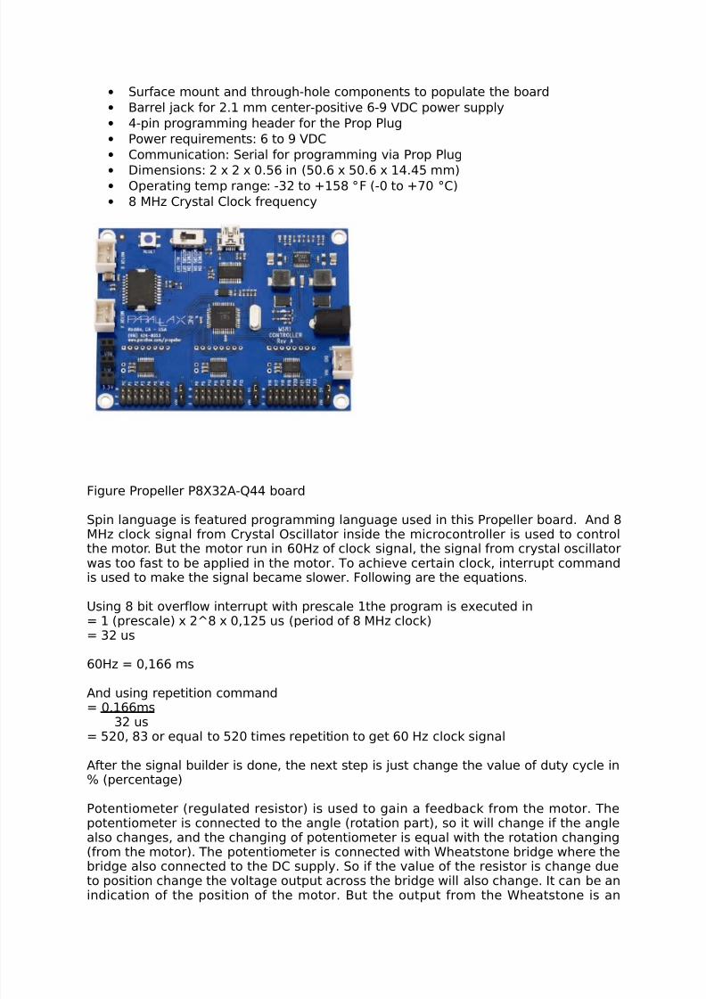
The H-bridge itself is embedded inside of the Control Board. In this time, PropellerP8X32A-Q44 microcontroller is used to control the motor. It has 23 output pin forServo Motor and 2 outputs for DC motor. The specifications of this board are:
• 512KB EEPROM for program and data storage
• 3.3 & 5.0 VDC on-board regulators
8/4/2019 Final Report on ARM
http://slidepdf.com/reader/full/final-report-on-arm 15/21
• Surface mount and through-hole components to populate the board
• Barrel jack for 2.1 mm center-positive 6-9 VDC power supply
• 4-pin programming header for the Prop Plug
• Power requirements: 6 to 9 VDC
• Communication: Serial for programming via Prop Plug
•
Dimensions: 2 x 2 x 0.56 in (50.6 x 50.6 x 14.45 mm)• Operating temp range: -32 to +158 °F (-0 to +70 °C)
• 8 MHz Crystal Clock frequency
Figure Propeller P8X32A-Q44 board
Spin language is featured programming language used in this Propeller board. And 8MHz clock signal from Crystal Oscillator inside the microcontroller is used to controlthe motor. But the motor run in 60Hz of clock signal, the signal from crystal oscillatorwas too fast to be applied in the motor. To achieve certain clock, interrupt commandis used to make the signal became slower. Following are the equations.
Using 8 bit overflow interrupt with prescale 1the program is executed in= 1 (prescale) x 2^8 x 0,125 us (period of 8 MHz clock)= 32 us
60Hz = 0,166 ms
And using repetition command= 0,166ms
32 us= 520, 83 or equal to 520 times repetition to get 60 Hz clock signal
After the signal builder is done, the next step is just change the value of duty cycle in% (percentage)
Potentiometer (regulated resistor) is used to gain a feedback from the motor. Thepotentiometer is connected to the angle (rotation part), so it will change if the anglealso changes, and the changing of potentiometer is equal with the rotation changing(from the motor). The potentiometer is connected with Wheatstone bridge where thebridge also connected to the DC supply. So if the value of the resistor is change dueto position change the voltage output across the bridge will also change. It can be anindication of the position of the motor. But the output from the Wheatstone is an
8/4/2019 Final Report on ARM
http://slidepdf.com/reader/full/final-report-on-arm 16/21
analog signal so it needs to be converted in digital signal to be used as a feedback inthe microcontroller. To get those conversion ADC chips is used.
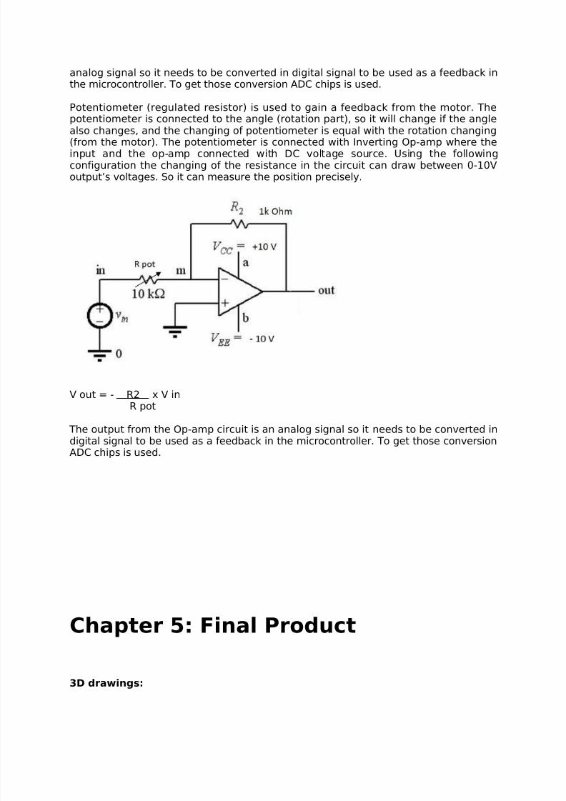
Potentiometer (regulated resistor) is used to gain a feedback from the motor. Thepotentiometer is connected to the angle (rotation part), so it will change if the anglealso changes, and the changing of potentiometer is equal with the rotation changing
(from the motor). The potentiometer is connected with Inverting Op-amp where theinput and the op-amp connected with DC voltage source. Using the followingconfiguration the changing of the resistance in the circuit can draw between 0-10Voutput’s voltages. So it can measure the position precisely.
V out = - R2 x V inR pot
The output from the Op-amp circuit is an analog signal so it needs to be converted indigital signal to be used as a feedback in the microcontroller. To get those conversionADC chips is used.
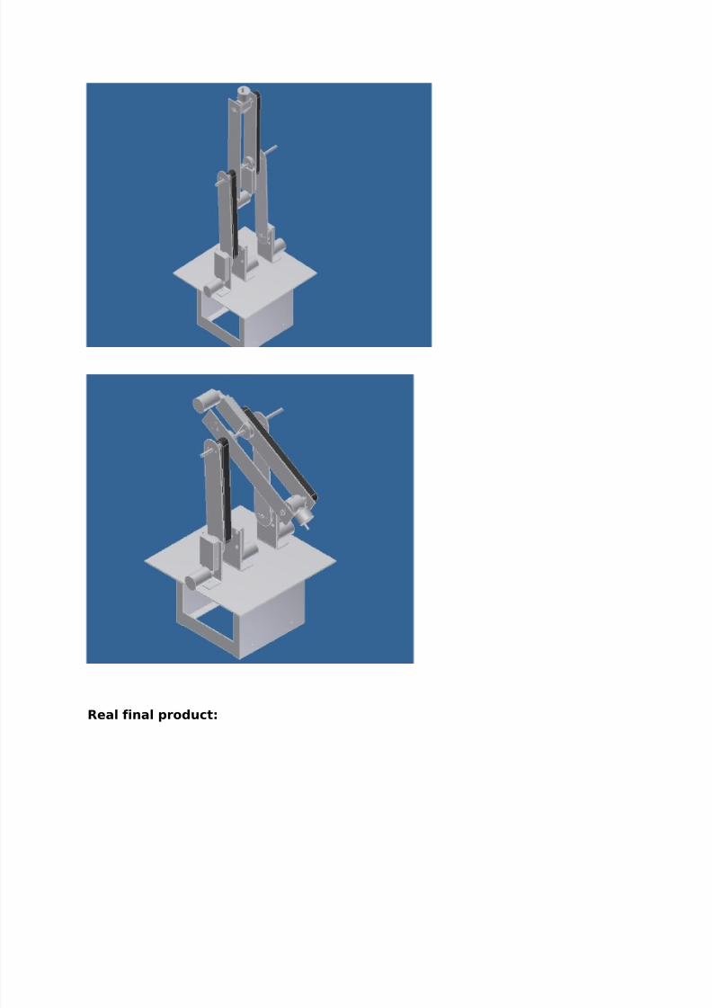
Chapter 5: Final Product
3D drawings:
8/4/2019 Final Report on ARM
http://slidepdf.com/reader/full/final-report-on-arm 17/21
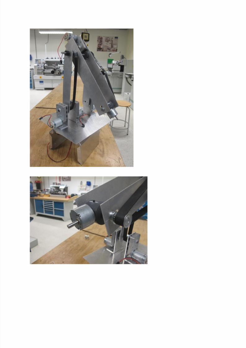
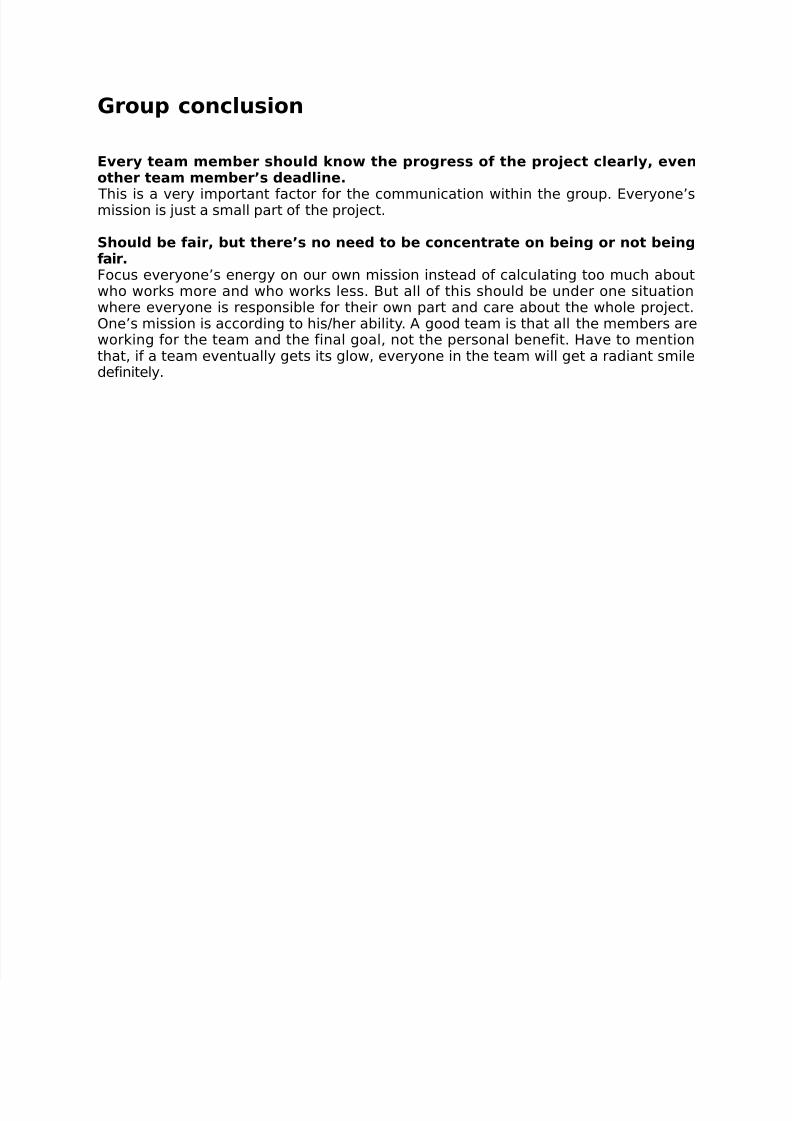
Real final product:
8/4/2019 Final Report on ARM
http://slidepdf.com/reader/full/final-report-on-arm 18/21

8/4/2019 Final Report on ARM
http://slidepdf.com/reader/full/final-report-on-arm 19/21

8/4/2019 Final Report on ARM
http://slidepdf.com/reader/full/final-report-on-arm 20/21
Chapter 6: Conclusion
Before finishing this final report, we are going to make a conclusion for this projectfrom three aspects, which are: project conclusion, technic conclusion and groupconclusion. Project conclusion is related to how we control the progress of the projectand what we learn from the project. Technic conclusion is kind of conclusion relatedto the knowledge of science and some technical tips for this project. Groupconclusion explains how we deal with the communication with the group during theproject.
Project conclusion
Having meeting with teacher once a week is very important.Holding Regular meeting once a week makes the members always be responsible forconcluding progress before the meeting and planning better after the meeting.
Communicate with tutors as much as possible.All the projects in school focus on education. Finishing the project is a mission, whilelearning something from it is the final goal. Group members always can get somenew inspirations from the conversation with the tutors.
Some deadlines can be postponed, under the situation where groupmembers have contemplated the reason and make sure can catch up later.Not everything can be controlled by people. Some progress can be stopped easily bya simple reason. No matter how simple it is, the group need to know what it is and
make sure the project can be caught up later. What if we can’t, and then change theplan.
Technic conclusion
The servo motor is easy to program but is not as strong as DC motor.
Using the spring on the lamp is good design. Actually the whole arm canbring the idea of the design of lamp.
There is much more space for improving the position of the motors.Considering the fact that the shoulder part, elbow part and wrist part should belighter and lighter in sequence; the position of the motor can influence the value of moment of inertia:
8/4/2019 Final Report on ARM
http://slidepdf.com/reader/full/final-report-on-arm 21/21
Group conclusion
Every team member should know the progress of the project clearly, evenother team member’s deadline.
This is a very important factor for the communication within the group. Everyone’smission is just a small part of the project. Should be fair, but there’s no need to be concentrate on being or not beingfair.Focus everyone’s energy on our own mission instead of calculating too much aboutwho works more and who works less. But all of this should be under one situationwhere everyone is responsible for their own part and care about the whole project.One’s mission is according to his/her ability. A good team is that all the members areworking for the team and the final goal, not the personal benefit. Have to mentionthat, if a team eventually gets its glow, everyone in the team will get a radiant smiledefinitely.