Embed Size (px)
Citation preview
Büro für Flugunfalluntersuchungen BFU Bureau d’enquête sur les accidents d’aviation BEAA Ufficio d’inchiesta sugli infortuni aeronautici UIIA Uffizi d'inquisiziun per accidents d'aviatica UIAA Aircraft Accident Investigation Bureau AAIB
Bundeshaus Nord, CH-3003 Bern
Final Report No. 1995
by the Aircraft Accident
Investigation Bureau
concerning the accident
to the Kamov KA-32A12 helicopter, registration HB-XKE
on 26 March 2002
“Ufem Schoren” municipality of Neuenegg/BE
approx. 15 km west of Berne-Belp airport
Final Report HB-XKE_26.03.02
Aircraft Accident Investigation Bureau Page 2 of 31
Ursachen
Der Unfall ist auf den nahezu gleichzeitigen Ausfall beider Triebwerke aufgrund einer Ver-wechslung eines Schalters zurückzuführen. Nach der Autorotation kippte der Helikopter nach der Landung auf die rechte Seite.
Zum Unfall beigetragen hat:
• Kombination eines Typenberechtigungsfluges mit einem technischen Flug
• Nicht angepasste Ergonomie der Schalter free turbine overspeed test und gas genera-tor test
• Fehlende technische Sicherheitsnetze
Final Report HB-XKE_26.03.02
General information on this report
This report contains the AAIB’s conclusions on the circumstances and causes of the accident which is the subject of the investigation.
In accordance with Annex 13 of the Convention on International Civil Aviation of 7 December 1944 and article 24 of the Federal Air Navigation Law, the sole purpose of the investigation of an aircraft accident or serious incident is to prevent future accidents or serious incidents. The legal assessment of accident/incident causes and circumstances is expressly no concern of the accident investigation. It is therefore not the purpose of this investigation to deter-mine blame or clarify questions of liability.
If this report is used for purposes other than accident prevention, due consideration shall be given to this circumstance.
The definitive version of this report is the original in the German language.
All times in this report unless otherwise indicated, are indicated in the standard time applica-ble to the area of Switzerland (local time – LT), corresponding at the time of the accident to Central European Time (CET). The relationship between LT, CET and coordinated universal time (UTC) is: LT = CET = UTC + 1 h.
For reasons of protection of privacy, the masculine form is used in this report for all natural persons, regardless of their gender.
Aircraft Accident Investigation Bureau Page 3 of 31
Final Report HB-XKE_26.03.02
Contents
Synopsis _______________________________________________________ 6 Summary _______________________________________________________ 6 Investigation ____________________________________________________ 6 1 Factual information _____________________________________________ 7
1.1 Flight preparation and history of the flight .......................................................... 7 1.1.1 General ..................................................................................................... 7 1.1.2 Flight preparation ...................................................................................... 7 1.1.3 History of the flight.................................................................................... 7
1.2 Injuries to persons ............................................................................................ 8 1.3 Damage to aircraft ............................................................................................ 8 1.4 Other damage .................................................................................................. 8 1.5 Personnel information ....................................................................................... 8
1.5.1 Flying instructor......................................................................................... 8 1.5.1.1 Flying experience______________________________________________ 9
1.5.2 Pilot .......................................................................................................... 9 1.5.2.1 Flying experience______________________________________________ 9
1.5.3 Examiner................................................................................................... 9 1.5.3.1 Flying experience_____________________________________________ 10
1.6 Aircraft information ..........................................................................................10 1.6.1 General ....................................................................................................10 1.6.2 Engine number 1 ......................................................................................11 1.6.3 Engine number 2 ......................................................................................12 1.6.4 Design characteristics and certification basis of helicopter KA-32A12............12 1.6.5 Cockpit and seating positions ....................................................................13 1.6.6 Regulation of rotor and engine speed ........................................................13
1.6.6.1 Hydromechanical Controller– system description ____________________ 14 1.6.6.2 Engine electronic governor EEG – system description ________________ 14 1.6.6.3 Free turbine overspeed prevention unit ___________________________ 15 1.6.6.4 Integration in the helicopter ____________________________________ 16 1.6.6.5 Maintenance regulations _______________________________________ 17
1.6.7 Engine adjustment procedure....................................................................17 1.7 Meteorological information ...............................................................................17
1.7.1 General ....................................................................................................17 1.7.2 General weather situation .........................................................................17 1.7.3 Meteorological conditions at the time and location of the accident ...............17 1.7.4 Natural light conditions .............................................................................17 1.7.5 Aerodrome weather reports.......................................................................18
1.8 Aids to navigation ............................................................................................18 1.9 Communications ..............................................................................................18 1.10 Aerodrome information ....................................................................................18 1.11 Flight recorders................................................................................................18
1.11.1 Flight data recorder ..................................................................................18 1.11.2 Cockpit voice recorder...............................................................................18 1.11.3 Flight data recorder read-out.....................................................................18 1.11.4 Installation regulations for flight data recorders in Switzerland ....................18
Aircraft Accident Investigation Bureau Page 4 of 31
Final Report HB-XKE_26.03.02
1.12 Wreckage and impact information.....................................................................19 1.12.1 Wreckage.................................................................................................19 1.12.2 Impact .....................................................................................................19 1.12.3 Accident site.............................................................................................19
1.13 Medical and pathological information.................................................................19 1.14 Fire .................................................................................................................20 1.15 Survival aspects ...............................................................................................20
1.15.1 General ....................................................................................................20 1.15.2 Emergency transmitter..............................................................................20
1.16 Tests and research...........................................................................................20 1.17 Organisational and management information.....................................................20
1.17.1 Heliswiss AG air operator ..........................................................................20 1.17.2 Swiss Helicopter Maintenance AG maintenance organisation........................20
1.18 Additional information ......................................................................................20 1.18.1 Speed limits according to the flight manual ................................................20 1.18.2 Emergency procedures according to the flight manual ................................20 1.18.3 Time requirement for re-starting an engine ................................................22
1.19 Useful or effective investigation techniques .......................................................22 2 Analysis _____________________________________________________ 23
2.1 Technical aspects.............................................................................................23 2.1.1 General ....................................................................................................23 2.1.2 Availability of FDR and CVR .......................................................................23 2.1.3 Availability of the engine speed regulator during the flight involved in the accident ...................................................................................................23 2.1.4 Technical explanation of the dual engine failure .........................................23
2.2 Human and operational aspects ........................................................................25 3 Conclusions __________________________________________________ 26
3.1 Findings ..........................................................................................................26 3.1.1 Technical aspects .....................................................................................26 3.1.2 Crew........................................................................................................26 3.1.3 History of the flight...................................................................................26 3.1.4 General conditions ....................................................................................26
3.2 Causes ............................................................................................................27 4 Safety recommendations and measures taken since the incident _________ 28
4.1 Safety recommendations ..................................................................................28 4.1.1 Safety deficit ............................................................................................28 4.1.2 Safety recommendation no. 256 (previous 46) with interim report dated 2 May 2002 ..............................................................................................28 4.1.3 FOCA comment dated 17 May 2002 ...........................................................28 4.1.4 Safety recommendation no. 256 to the European Aviation Safety Authority EASA .........................................................................................29
4.2 Measures taken since the accident ....................................................................29 4.2.1 Interim modifications of the switches by Heliswiss AG.................................29
Annex 1 _______________________________________________________ 30 Annex 2 _______________________________________________________ 31
Aircraft Accident Investigation Bureau Page 5 of 31
Final Report HB-XKE_26.03.02
Final Report
Owner Heliswiss AG, 3123 Belp, Switzerland
Operator Heliswiss AG, 3123 Belp, Switzerland
Aircraft type Kamov KA-32A12
Country of registration Switzerland
Registration HB-XKE
Location “Ufem Schoren” municipality of Neuenegg/BE
Date and time 26 March 2002 at approximately 16:12
Synopsis
The accident was reported to the Russian investigating authority, the IAC Air Accident Inves-tigation Commission, and the manufacturer by means of ACCID.
According to Annexe 13 of the Convention on International Civil Aviation (ICAO Annex 13), the state of manufacture of the aircraft has the option of sending authorised representatives to the investigation. This option was exercised. The representatives of the IAC arrived in Belp on 28.03.02 and accompanied the investigation.
Summary
On the afternoon of 26 March 2002 the twin-engine Kamov KA-32A12 helicopter, registration HB-XKE, took off from Berne-Belp aerodrome on a type rating flight. On the return flight, the flying instructor carried out a technical engine test. When he did so, both engines cut out, almost simultaneous. The pilot then initiated an autorotation and landed in a field. On touch-down, the helicopter tipped onto its right side. The aircraft was severely damaged. The oc-cupants were unharmed.
Investigation
The notification was received at the Aircraft Accident Investigation Bureau (AAIB) at ap-proximately 16:20. The investigation was opened at the site at approximately 18:45 by the AAIB in cooperation with the Berne cantonal police.
The accident is attributable to the almost simultaneous failure of both engines because of confusion over a switch. After the autorotation, the helicopter tipped over on its right side after landing.
The following factors contributed to the accident:
• the combination of a type rating flight with a technical flight
• inappropriate ergonomics of the free turbine overspeed test and gas generator test switches
• a lack of technical safeguards
Within the framework of the investigation, one safety recommendation was made.
Aircraft Accident Investigation Bureau Page 6 of 31
Final Report HB-XKE_26.03.02
Aircraft Accident Investigation Bureau Page 7 of 31
1 Factual information
1.1 Flight preparation and history of the flight
1.1.1 General
For the description of the flight preparation and history of the flight, the re-cordings of the cockpit voice recorder and the statements of the crew members were used.
The flight took place under visual flight rules.
1.1.2 Flight preparation
On 25 March 2002, i.e. one day before the accident, a 100-hour check was car-ried out on helicopter HB-XKE, on the airframe and the engines. During the tech-nical check flight it was established that the engine limiters were functioning, but not the associated warning lamps. The helicopter was cleared for flying opera-tions.
The appropriate adjustments were made on the ground after the flight, on the basis of the measured data.
A type rating examination flight was scheduled for the afternoon of 26 March 2002. In order to provide the pilot with a further training opportunity, a flight was made on the morning of 26 March 2002. During the flight the engine pa-rameters were checked and it was found that the engine limiter of the right en-gine was continuing to reduce power without the warning lamp lighting up. The settings were subsequently corrected once more.
1.1.3 History of the flight
At 15:22 on 26 March 2002, the twin-engine Kamov KA-32A12 helicopter took off from Berne-Belp aerodrome on the type rating examination flight. On board were the examination candidate, in the left-hand seat, the flying instructor in the right hand seat and the examiner from the Federal Office of Civil Aviation in the ob-server’s seat.
The flight progressed from the Heliswiss AG base in the direction of departure waypoint “HW”. During the climb, the crew once again tested the engine power limiters. This took place after prior consultation with the examiner.
In the Schwarzenburg – Laupen – Grosses Moos area, the manoeuvres required for the examination were flown. At approximately 16:06 the examiner asked for a dual engine failure to be simulated. The pilot immediately initiated an autorota-tion, which took place successfully. The candidate was then requested to carry out a quick stop at 2500 ft QNH near the Gümmenenbrücke bridge. This ended the examination programme.
At approximately 16:09 the pilot reported on the aerodrome control (Berne Tower) frequency “Berne from helicopter HB-XKE, Laupen, 3000 ft, Information U, for landing Heliswiss“. He received clearance from the aerodrome controller to fly into the aerodrome traffic zone and was requested to report at approach waypoint “HW".
At approximately 16:11 the helicopter was in the Oberwangen area at 1000 m/AMSL. The flying instructor, in his capacity as test pilot, carried out pre-liminary operations for an engine test, during which various audio warnings sounded immediately. Both engines cut out almost simultaneous. The pilot then initiated an autorotation. The crew mentioned the tailwind. On final approach, the speed was a little over 100 km/h. The helicopter touched down on a field ap-
Final Report HB-XKE_26.03.02
proximately 40 seconds after the dual engine failure at a forward speed of ap-proximately 15 km/h. On landing, the aircraft tipped onto its right side. The heli-copter was severely damaged. The occupants were unharmed.
The pilot was PF throughout the flight.
1.2 Injuries to persons
Injuries Crew Passengers Total number of occupants
Others
Fatal --- --- --- ---
Serious --- --- --- ---
Minor --- --- --- ---
None 3 --- 3 ---
Total 3 --- 3
1.3 Damage to aircraft
The helicopter was severely damaged.
1.4 Other damage
There was damage to agricultural land caused by the impact and salvaging of the helicopter and by leaking kerosene.
The site of the accident has since been renatured.
1.5 Personnel information
1.5.1 Flying instructor
Person Swiss citizen, born 1953
Licence Commercial Pilot Licence, helicopter CPL (H), issued by the FOCA, valid till 19.11.2000 Private Pilot Licence, helicopter PPL (H), issued by the FOCA, valid till 19.05.2002
Ratings Flying instructor FI(H), valid till 05.06.2004 Radiotelephony RTI Night flying, helicopter NIT(H) Mountain landings MOU (H)
Rated helicopter types A 109, AL II, AL III, AS 350 Types, AS 355, B 171 SYCAMORE, B 205, B 206 / 206L, B 212 PIC, B 214 PIC, B 407, B 47 SOLOY, B 47 Types, Bell 204, BH06/ST/LT, BK117, BO 105, Hughes 300, Hughes 500, KAMOV KA 32, R 22, SA 315
Medical fitness certificate Class 2, without restrictions
Last medical examination 19.05.2000
Aircraft Accident Investigation Bureau Page 8 of 31
Final Report HB-XKE_26.03.02
1.5.1.1 Flying experience
Total 3773:06 hours
on the accident type 167:47 hours
during the last 90 days 24:25 hours
of which on the accident type 13:32 hours
during the last 24 hours 1:48 hours
of which on the accident type 1:48 hours
Landings, total 29 015
1.5.2 Pilot
Person Swiss citizen, born 1954
Licence Commercial Pilot Licence, helicopter CPL (H), issued by the FOCA, valid till 06.07.2002 Private Pilot Licence, helicopter PPL (H), issued by the FOCA, valid till 06.01.2004
Ratings Flying instructor FI(H), valid till 19.06.03 Radiotelephony RTI Night flying, helicopter NIT(H) Mountain landings MOU (H)
Rated helicopter types AL II, AL III, AS 350 Types, B 206 / 206L, B 214, B 407, B 47 Types, Hughes 300, Hughes 500, SA 315
Medical fitness certificate Class 1, without restrictions
Last medical examination 18.12.2001
1.5.2.1 Flying experience
Total 10 180:05 hours
on the accident type 12:01 hours
during the last 90 days 22:16 hours
of which on the accident type 12:01 hours
during the last 24 hours 2:10 hours
of which on the accident type 2:10 hours
Landings, total 90 069
1.5.3 Examiner
Person Swiss citizen, born 1942
Licence Commercial Pilot Licence, helicopter CPL (H), issued by the FOCA, valid till 10.06.2002
Aircraft Accident Investigation Bureau Page 9 of 31
Final Report HB-XKE_26.03.02
Ratings Flying instructor FI(H) Examiner TRE(H) Radiotelephony RTI Night flying, helicopter NIT(H) Mountain landings MOU (H)
Rated helicopter types A 109 E, AL II, AL III, AS 350 Types, B 206 / 206L, MD900/902, SA318/SE313, SA 315, SA 365
Medical fitness certificate Class 1, without restrictions
Last medical examination 10.12.2001
1.5.3.1 Flying experience
Total Approx. 3850 hours
on the accident type None
On board in his capacity as Federal Office of Civil Aviation examiner.
1.6 Aircraft information
1.6.1 General
Registration HB-XKE
Aircraft type KA-32A12
Characteristics Twin-engine transport helicopter with co-axial, counter-rotating rotor system
Manufacturer Kamov Company, Moscow, Russia
Year of construction 1992
Serial number 8709/02 (31587)
Owner Heliswiss AG, 3123 Belp, Switzerland
Operator Heliswiss AG, 3123 Belp, Switzerland
Engine 2 Klimov TV3-117VMA
Auxiliary Power Unit (APU) Type AI-9
Operating hours, airframe 2606:04 hours
Airframe, number of landings 7372
Max. permitted take-off mass 11 t
Mass and centre of gravity The mass of the aircraft at the time of the accident was approximately 8595 kg. Both the mass and centre of gravity were within the permitted limits according to the AFM.
Maintenance Swiss Helicopter Maintenance AG (SHM AG), Berne Airport, 3123 Belp, SwitzerlandThe last 100-hour check on the airframe and engines was carried out and certifi-cated by SHM AG on 25.03.2002.
Aircraft Accident Investigation Bureau Page 10 of 31
Final Report HB-XKE_26.03.02
Technical limitations The following points were entered in the logbook on 26.03.02: “a) Limiter test flight (24’). RH Eng.
not ok. b) Training conversion examination
(56’)”
Fuel grade JET A1 kerosene The fuel sample contained very few solid particles. Otherwise, the sample complied with the tested points of the requisite specification.
Fuel reserves At the time of the accident there were about 1275 kg of fuel on board.
Registration certificate Issued by the FOCA on 12.06.1996 / No. 1
Airworthiness certificate Special category / Restricted. Issued by the FOCA on 17.06.1996, valid till revoked.
Certification in non-commercial use VFR day & night only; Aerial work with internal or external load; Crew training & proficiency flights; Technical & positioning flights; No transport of passengers for remuneration or hire; Transport of pas-sengers limited to persons directly in-volved with aerial work
Certification in commercial use VFR day & night only The validation conditions apply to these types of use.
Last airworthiness inspection Carried out by the FOCA on 10.08.2001.
1.6.2 Engine number 1
Serial number 7087853703620
Year of construction Unknown
Installation location on HB-XKE Left side in October 1999 at: - Operating time since manu-
facture 575:00 hours
- Flying cycles since manufac-ture
No information
- Operating time, helicopter 1652:58 hours
Operating time since manufacture 1528:06 hours
Flight cycles since overhaul 1310
Operating time since installation in HB-XKE
953:06 hours
Aircraft Accident Investigation Bureau Page 11 of 31
Final Report HB-XKE_26.03.02
1.6.3 Engine number 2
Serial number 7087893000316
Year of construction Unknown
Installation location on HB-XKE Right side in October 1999 at: - Operating time since manufacture 1052:16 hours - Flying cycles since manufacture No information - Operating time, helicopter 1652:58 hours
Operating time since manufacture 2005:22 hours
Flight cycles since overhaul 1310
Operating time since installation in HB-XKE
953:06 hours
1.6.4 Design characteristics and certification basis of helicopter KA-32A12
Helicopter KA-32 was developed by the Kamov company as a civil transport heli-copter based on the KA-27 submarine hunter helicopter and features the design characteristics typical of Kamov: a compact fuselage of very robust construction with a co-axial rotor system.
The helicopter with registration RA-31587 was imported into Switzerland as KA-32A. After extensive conversion work and validation by the Federal Office of Civil Aviation, it received registration mark HB-XKE and was now designated KA-32A12.
The type KA-32A12 helicopter was certificated as follows, according to informa-tion in the rotorcraft flight manual (RFM), Section 1 Limitations:
“This helicopter is certified under NLG 32.29 and FAR Part 29, Category A and B. Note: NLG 32.29 requirements in their structure and contents are equivalent to FAR Part 29, Amendment 29-1 to 29-24.”
The Federal Aviation Regulations (FAR) PART 29 - AIRWORTHINESS STAN-DARDS: TRANSPORT CATEGORY ROTORCRAFT require, among other things:
Ҥ 29.777 Cockpit controls.
Cockpit controls must be—
(a) Located to provide convenient operation and to prevent confusion and inad-vertent operation; and…..
§ 29.903 Engines.
(b) Category A: engine isolation. For each category A rotorcraft, the powerplants must be arranged and isolated from each other to allow operation, in at least one configuration, so that the failure or malfunction of any engine, or the failure of any system that can affect any engine, will not—
(1) Prevent the continued safe operation of the remaining engines; or
(2) Require immediate action, other than normal pilot action with primary flight controls, by any crewmember to maintain safe operation.
Aircraft Accident Investigation Bureau Page 12 of 31
Final Report HB-XKE_26.03.02
§ 29.1353 Electrical equipment and installations.
(a) Electrical equipment, controls, and wiring must be installed so that operation of any one unit or system of units will not adversely affect the simultaneous op-eration of any other electrical unit or system essential to safe operation.”
1.6.5 Cockpit and seating positions
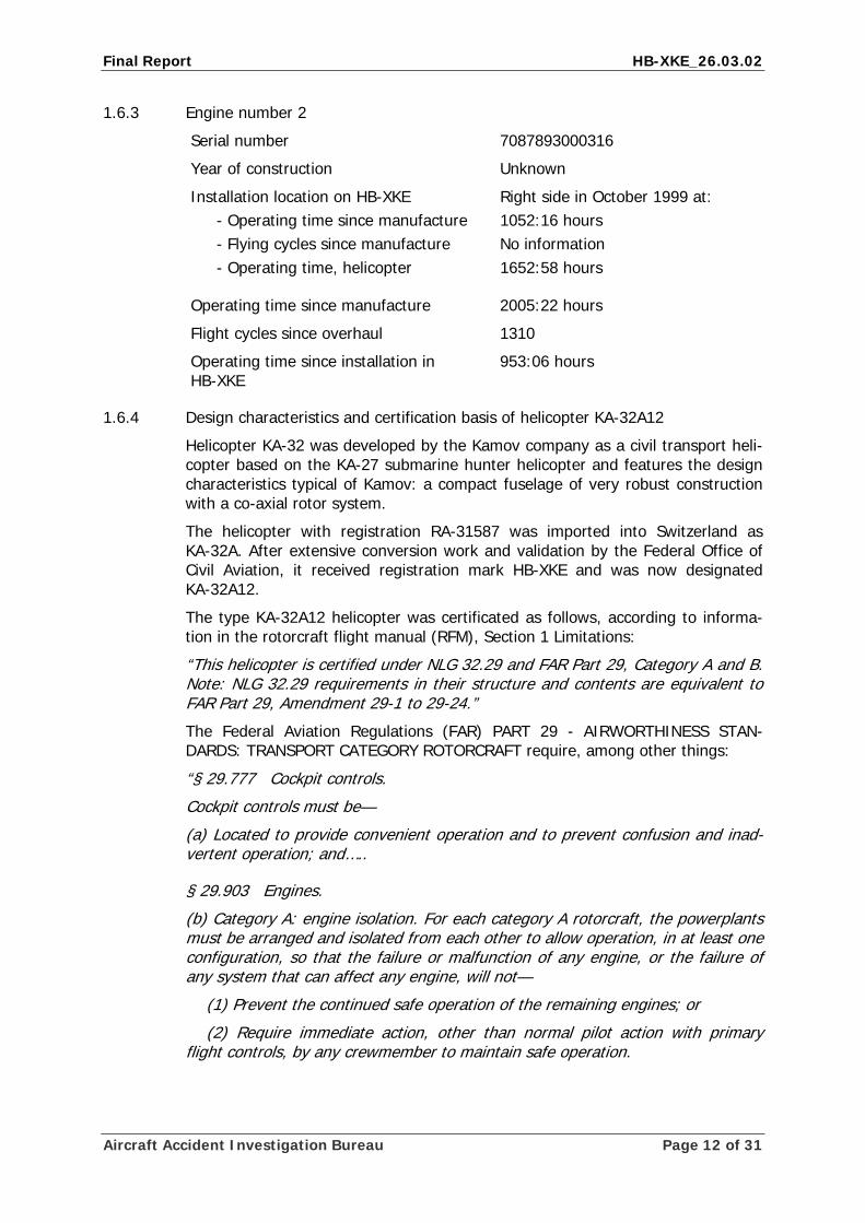
Helicopter HB-XKE has conventional cockpit equipment. The instruments display metric scales. On the right-hand side of the instrument panel there is a panel of warning lamps (annunciator panel), which is coupled with an audio warning sys-tem. The light blue colour of the panels is distinctive. The left seat is for the pilot flying. The dual controls were installed on the right-hand side.
The relevant controls can be operated from either side.
Fig. 1: Cockpit Layout – Instrument panel and upper part of the centre console
1.6.6 Regulation of rotor and engine speed
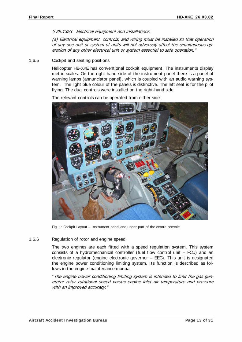
The two engines are each fitted with a speed regulation system. This system consists of a hydromechanical controller (fuel flow control unit – FCU) and an electronic regulator (engine electronic governor – EEG). This unit is designated the engine power conditioning limiting system. Its function is described as fol-lows in the engine maintenance manual:
"The engine power conditioning limiting system is intended to limit the gas gen-erator rotor rotational speed versus engine inlet air temperature and pressure with an improved accuracy.”
Aircraft Accident Investigation Bureau Page 13 of 31
Final Report HB-XKE_26.03.02
Fig. 2: Block diagram of an engine conditioning limiting system
The nominal rotor speed (NR) of the KA-32A12 when cruising is 90%; this corre-sponds to 272.2 rpm.
1.6.6.1 Hydromechanical Controller– system description
The hydromechanical controller (fuel control unit - FCU) regulates the fuel flow to the engine under all operating conditions including startup and shutdown In ad-dition, the FCU controls the engine’s variable guide vanes (VGV). The helicopter’s fuel serves as the operating medium. The FCU is mounted laterally on each en-gine’s external gearbox.
The fuel flow to the engine combustion chamber is cut off by means of the en-gine shutdown actuator.
1.6.6.2 Engine electronic governor EEG – system description
The engine electronic governor EEG is part of the engine conditioning limiting system and acts on the fuel flow control unit actuator and the engine shutdown actuator.
The EEG is responsible for the following functions, among other things:
• limits the gas generator speed (Ngg) at maximum take-off power as a func-tion of T0 and P0.
• limits Ngg at the 2.5 minute power in the event of an engine failure (OEI) as a function of T0 and P0.
• gas generator speed can be reduced by 4% by means of the turbo com-pressor switch.
• in the event of a free turbine overspeed, generates a signal which acts on the engine shutdown actuator and the L (R) ENG FT OVERSPEED annuncia-tors.
Aircraft Accident Investigation Bureau Page 14 of 31
Final Report HB-XKE_26.03.02
Aircraft Accident Investigation Bureau Page 15 of 31
The EEG consists of the following functional components:
• Electrical power supply (+27 V DC)
• Free turbine overspeed prevention unit (FTOPU)
• Gas generator rotational speed limiting circuit (CC circuit)
1.6.6.3 Free turbine overspeed prevention unit
The free turbine overspeed prevention unit (FTOPU) consists of two identical channels and one test circuit.
In Section 073.15.04 of the engine maintenance manual, this function is de-scribed as follows:
“When the rotational speed of the free turbine reaches 118 ±2 %1 the two chan-nels of the FTOPU operate and a command is applied through a power amplifier to the FTOPA actuator (to shut down the engine) and to the L (R) ENG FT OVER-SPEED annunciator. Whenever only one of the FTOPU channels operates, the signal is not generated to go to the FTOPA: a command with a self interlock is in-stead applied to the L (R) ENG FT OVERSPEED annunciator of the channel that has operated.
If the second channel fails to operate in 0.2 s the test circuit generates a com-mand to reset both channels, i.e. to bring them to the initial state. The L (R) ENG FT OVERSPEED signal is therewith removed.
FTOPU Test Mode:
The FTOPU may be tested channel-by-channel or integrally. In testing the FTOPU channel-by-channel TEST 12 or TEST 2 signal is applied to the FTOPU (depending on the number of channels which is intended to be tested). In response to this signal the boundaries of the FTOPU operation range become reduced to Nft 96 ±2 %3: the maximum limit speed in the test mode (Nft test) is thus lower than Nftlim.
This makes it possible to check the correctness of operation of the channel in operating the EEG without gaining the Nft im speed.
When the FTOPU test selector switch is turned to TEST 1 or TEST 2 position the operation of one of the channels is checked and a signal is applied to the L (R) ENG FT OVERSPEED annunciator. The channel under test becomes therewith self-interlocked. The channel interlock in the TEST mode is removed on elapse of 0.2 s after the selector switch is placed to the OPERATION4 position. The FTOPU with FTopa operation and interlock may be tested by placing the selector switch from TEST 1 to TEST 2 position without holding it in the OPERATION position for 0.2 s. The self interlock is in this case removed by de-energizing the engine elec-tronic governor.”
1 On the KA-32A12, a power turbine speed of 118% corresponds to a power turbine speed of 106.2 %.
2 TEST 1 and TEST 2 correspond to the designations CIRC 1 and CIRC 2 of the free turbine overspeed test switch on the centre console.
3 On the KA-32A12, a power turbine speed of 96 % corresponds to a power turbine speed of 86.4 %. 4 OPERATION corresponds to the OPER designation of the free turbine overspeed test switch on the centre
console.
Final Report HB-XKE_26.03.02
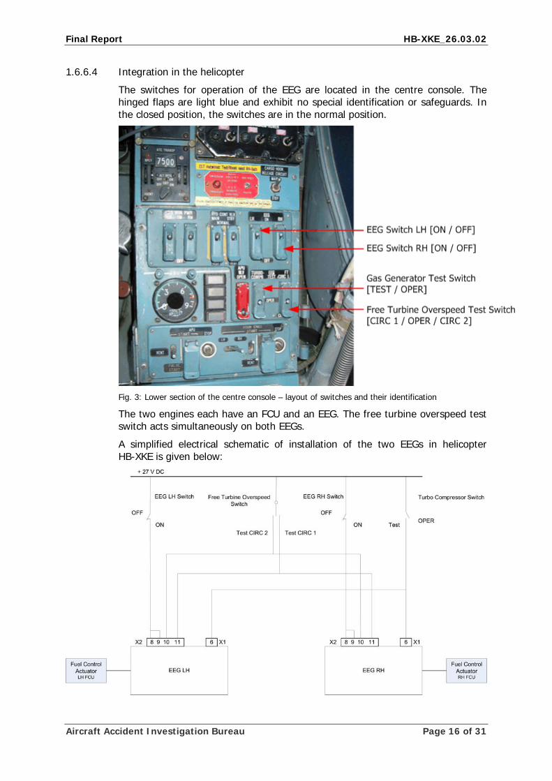
1.6.6.4 Integration in the helicopter
The switches for operation of the EEG are located in the centre console. The hinged flaps are light blue and exhibit no special identification or safeguards. In the closed position, the switches are in the normal position.
Fig. 3: Lower section of the centre console – layout of switches and their identification
The two engines each have an FCU and an EEG. The free turbine overspeed test switch acts simultaneously on both EEGs.
A simplified electrical schematic of installation of the two EEGs in helicopter HB-XKE is given below:
Aircraft Accident Investigation Bureau Page 16 of 31
Final Report HB-XKE_26.03.02
1.6.6.5 Maintenance regulations
The maintenance instructions (Maintenance Manual 005.20.20) for the Klimov TV3-117VMA engine require the following points, among others, to be checked after a 100-hour inspection:
• Main rotor RPM regulator adjustment
• GG EEG circuit check
• Free turbine circuit check
• Check of the gas generator RPM at take-off and contingency ratings (with GG EEG circuit on)
1.6.7 Engine adjustment procedure
In order to determine the parameters of the hydromechanical controller, the cor-responding engine’s EEG must be switched off by means of the EEG LH or EEG RH switch. This de-activates the electronic part of the regulation circuit.
Testing of the free turbine overspeed prevention unit takes place on the ground with the engines running. Activation of the test sequence in the air is possible, i.e. it is not prevented by technical means.
1.7 Meteorological information
1.7.1 General
The information in sections 1.7.2 to 1.7.5 was provided by MeteoSwiss.
1.7.2 General weather situation
“A ridge of high pressure extended from the British Isles to the Baltic. A weak ‘bise’ airflow prevailed on the northern side of the Alps, at the southern edge of this high-pressure area.”
1.7.3 Meteorological conditions at the time and location of the accident
The following information on the meteorological conditions at the time and loca-tion of the accident is based on a spatial and chronological interpolation of the observations of different weather stations.
Weather/cloud 1-2/8, base at 5500 ft AMSL
Visibility about 12 km
Wind 030°, 8 kt, gusting to 15 kt
Temperature/dewpoint +7 °C / -4 °C
Atmospheric pressure QNH LSZB 1022 hPa QNH LSZH 1024 hPa
Hazards -
1.7.4 Natural light conditions
Position of the sun Azimuth: 243° Elevation: 26°
Natural light conditions Daylight
Aircraft Accident Investigation Bureau Page 17 of 31
Final Report HB-XKE_26.03.02
1.7.5 Aerodrome weather reports
METAR Berne-Belp (LSZB) aerodrome, 15:20 UTC:
07007 8000 FEW035 08/M03 Q1022 NOSIG =
1.8 Aids to navigation
Not applicable.
1.9 Communications
Radio communication between the crew and the Berne-Belp aerodrome air traffic controller took place normally and without any difficulties up to the time of the accident.
1.10 Aerodrome information
Not applicable.
1.11 Flight recorders
A BUR-1 flight data recorder (FDR) and a MARS-BM cockpit voice recorder were installed in the tailboom of helicopter HB-XKE.
After the accident, both devices were in their installed position and were exter-nally intact.
1.11.1 Flight data recorder
Type BUR-1
Parameters Various analogue and discrete parameters
Recording medium Analogue, tape loop
Duration of recording 50 ±10 hours
1.11.2 Cockpit voice recorder
Type MARS-BM
Parameters Four voice channels
Recording medium Analogue, tape loop
Duration of recording Min. 30 minutes
1.11.3 Flight data recorder read-out
The Russian investigating authorities were charged with downloading the data from the flight data recorder and the CVR. Both devices were in good condition.
• The recordings from the flight data recorder could not be analysed because of a device malfunction of which the owner was aware.
• Comprehensibility of the CVR recordings was good and the recordings were complete.
1.11.4 Installation regulations for flight data recorders in Switzerland
The installation of FDR and CVR was not prescribed at the time of the accident.
Aircraft Accident Investigation Bureau Page 18 of 31
Final Report HB-XKE_26.03.02
1.12 Wreckage and impact information
1.12.1 Wreckage
A visual inspection of the wreckage provided no indications of pre-existing de-fects.
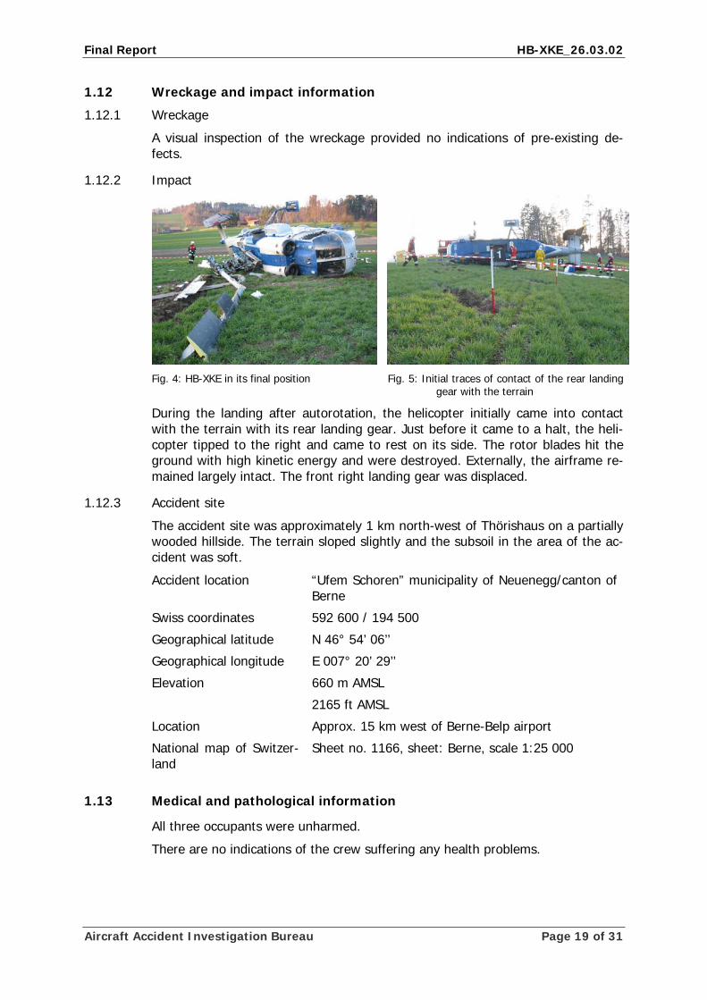
1.12.2 Impact
Fig. 4: HB-XKE in its final position Fig. 5: Initial traces of contact of the rear landing
gear with the terrain
During the landing after autorotation, the helicopter initially came into contact with the terrain with its rear landing gear. Just before it came to a halt, the heli-copter tipped to the right and came to rest on its side. The rotor blades hit the ground with high kinetic energy and were destroyed. Externally, the airframe re-mained largely intact. The front right landing gear was displaced.
1.12.3 Accident site
The accident site was approximately 1 km north-west of Thörishaus on a partially wooded hillside. The terrain sloped slightly and the subsoil in the area of the ac-cident was soft.
Accident location “Ufem Schoren” municipality of Neuenegg/canton of Berne
Swiss coordinates 592 600 / 194 500
Geographical latitude N 46° 54’ 06’’
Geographical longitude E 007° 20’ 29’’
Elevation 660 m AMSL
2165 ft AMSL
Location Approx. 15 km west of Berne-Belp airport
National map of Switzer-land
Sheet no. 1166, sheet: Berne, scale 1:25 000
1.13 Medical and pathological information
All three occupants were unharmed.
There are no indications of the crew suffering any health problems.
Aircraft Accident Investigation Bureau Page 19 of 31
Final Report HB-XKE_26.03.02
1.14 Fire
Fire did not break out. The rescue services were able to pump approximately 900 l of fuel out of the tanks.
1.15 Survival aspects
1.15.1 General
The lap and shoulder belts were being worn and withstood the deceleration forces.
The accident was survivable.
The helicopter’s very compact construction protected the occupants well.
1.15.2 Emergency transmitter
The helicopter was equipped with a Jolliet JE 290-95-00 emergency transmitter (emergency location beacon aircraft – ELBA). The device was installed and was not triggered.
1.16 Tests and research
Not applicable.
1.17 Organisational and management information
1.17.1 Heliswiss AG air operator
The Heliswiss AG company, based in Belp, was founded in 1953 and is active in the passenger and external cargo transport sector. Furthermore, Heliswiss oper-ates a flying school.
A KA-32 has been in operation since 1990. A pilot was available to operate the helicopter. This pilot was on holiday till 7 April 2002. No pilot had yet been as-signed for missions from 27.03.2002.
1.17.2 Swiss Helicopter Maintenance AG maintenance organisation
The Swiss Helicopter Maintenance AG (SHM) company was founded in 2001. At the time, among other things, the maintenance organisation of the Heliswiss AG company were integrated into the new company. From this time, maintenance on Heliswiss AG helicopters was carried out by SHM.
1.18 Additional information
1.18.1 Speed limits according to the flight manual
In the flight manual for HB-XKE, the minimum indicated air speed during an autorotation is defined as 100 km/h.
1.18.2 Emergency procedures according to the flight manual
The following procedural instructions in the event of a dual engine failure are de-fined in the flight manual:
Aircraft Accident Investigation Bureau Page 20 of 31
Final Report HB-XKE_26.03.02
“…
COLLECTIVE - FULL DOWN immediately
Establish autorotative glide at airspeed 100…130 km/h IAS
Turn to the direction of the nearest landing site
Accomplish autorotative landing
If time permits before landing shutdown engines as follows:
Fuel shut-off levers - CLOSE
Fuel shut-off valves - OFF”
The following procedural instructions in the event of an autorotative landing are defined in the flight manual:
“Proceed as follows:
Approach - upwind (if possible)
Establish airspeed 100 km/h IAS at 50 meters altitude
At 50 meters altitude and down to landing perform descent with continuous vis-ual check of height
Landing without running
Accomplish flareout at 50…30 meters altitude depending on the approach speed as follows:
CYCLIC –pitch angle of up to 25 degrees
COLLECTIVE – UP to 2/3 of full travel
Maintain pitch angle up to complete deceleration at up to 3 meters height
At 3 meters height CYCLIC apply forward to achieve landing attitude
NOTE
Pitch angle is limited for landing 10 degrees maximum
Pitch angle is limited for ditching 15 degrees maximum
Simultaneously COLLECTIVE – UP to the upper stop
Accomplish landing on the main wheels with minimum forward speed and rate of descent
…….
Running landing
Accomplish flareout at 50…30 meters
CYCLIC smoothly nose up to achieve landing attitude (pitch 8…10 degrees) at 1…1,5 meters height
At 1…1,5 meters height COLLECTIVE – FULL UP, if required to land smoothly on the main wheels with minimum forward speed and rate of descent
During running at speed 40 km/h
COLLECTIVE – move smoothly to the lower stop
….”
Aircraft Accident Investigation Bureau Page 21 of 31
Final Report HB-XKE_26.03.02
1.18.3 Time requirement for re-starting an engine
Extensive manipulations have to be carried out to start an engine after a dual engine failure. Among other things, it is essential to start the auxiliary power unit (APU) beforehand. This process takes about 13 seconds. The APU should then be established for one minute. The engine start is then initiated. The engine start is concluded after approximately 36 seconds.
If the engine power lever is moved in 1 – 2 seconds from the idle position to the start (FT) position, acceleration times of approximately 8 seconds result. The power build-up which is possible from this moment requires an additional few seconds.
The time required for the entire sequence is therefore at least one minute, this under the condition, that the APU will not be stabilised for the duration of one minute.
1.19 Useful or effective investigation techniques
Not applicable.
Aircraft Accident Investigation Bureau Page 22 of 31
Final Report HB-XKE_26.03.02
2 Analysis
2.1 Technical aspects
2.1.1 General
The helicopter made its first flight after the 100-hour check on 25.03.2002. No release for test flight was generated for this flight. The only outstanding point was the adjustment of the engine limiter for the right engine.
The two step release-procedure with
a) Release for testflight only
b) Release to service
was not yet introduced by SHM at the time of the accident.
The helicopter was released for flight operations on the same day with the re-lease to service.
Checking of engine adjustment for this helicopter is specified in the manufac-turer’s maintenance manual. Since the adjustments are made iteratively, the number of technical flights required varies.
Apart from the area of the engine speed regulation system, there are no indica-tions of any pre-existing technical faults which might have caused the accident.
2.1.2 Availability of FDR and CVR
An FDR and CVR were installed in the helicopter. There were no FOCA regula-tions in this regard. It was possible to analyse the CVR without any problems and this provided very useful information. Unfortunately, analysis of the FDR was not possible for technical reasons. The AAIB considers it inappropriate that such sys-tems are not maintained in operating condition.
2.1.3 Availability of the engine speed regulator during the flight involved in the acci-dent
Both the hydromechanical and electronic engine speed controllers were available for both engines.
2.1.4 Technical explanation of the dual engine failure
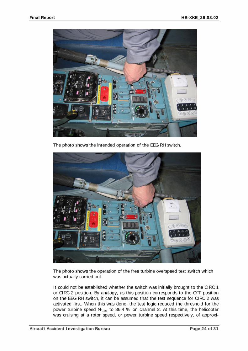
In order to be able to test the right engine hydromechanical controller, the flight instructor intended to operate the EEG RH switch, thereby switching off the elec-tronic controller. Because of confusion, the free turbine overspeed test switch, which is located in the same column of switches but one row further back, was operated.
Aircraft Accident Investigation Bureau Page 23 of 31
Final Report HB-XKE_26.03.02
The photo shows the intended operation of the EEG RH switch.
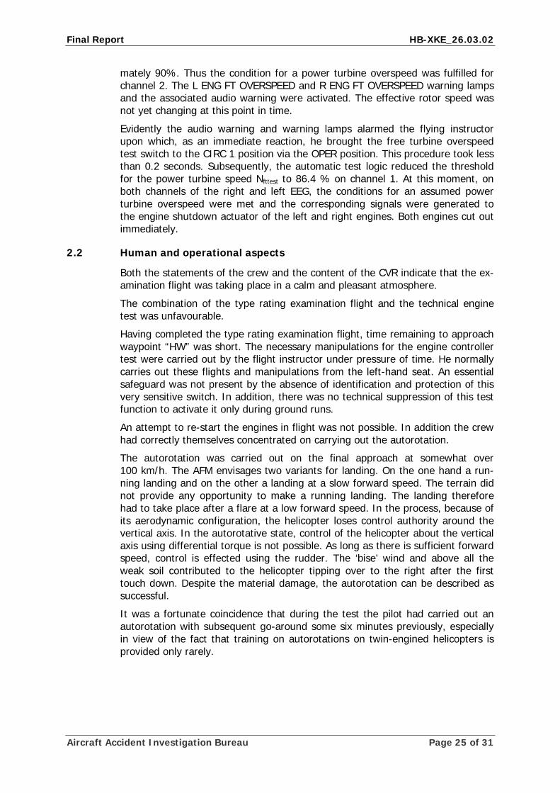
The photo shows the operation of the free turbine overspeed test switch which was actually carried out.
It could not be established whether the switch was initially brought to the CIRC 1 or CIRC 2 position. By analogy, as this position corresponds to the OFF position on the EEG RH switch, it can be assumed that the test sequence for CIRC 2 was activated first. When this was done, the test logic reduced the threshold for the power turbine speed Nfttest to 86.4 % on channel 2. At this time, the helicopter was cruising at a rotor speed, or power turbine speed respectively, of approxi-
Aircraft Accident Investigation Bureau Page 24 of 31
Final Report HB-XKE_26.03.02
mately 90%. Thus the condition for a power turbine overspeed was fulfilled for channel 2. The L ENG FT OVERSPEED and R ENG FT OVERSPEED warning lamps and the associated audio warning were activated. The effective rotor speed was not yet changing at this point in time.
Evidently the audio warning and warning lamps alarmed the flying instructor upon which, as an immediate reaction, he brought the free turbine overspeed test switch to the CIRC 1 position via the OPER position. This procedure took less than 0.2 seconds. Subsequently, the automatic test logic reduced the threshold for the power turbine speed Nfttest to 86.4 % on channel 1. At this moment, on both channels of the right and left EEG, the conditions for an assumed power turbine overspeed were met and the corresponding signals were generated to the engine shutdown actuator of the left and right engines. Both engines cut out immediately.
2.2 Human and operational aspects
Both the statements of the crew and the content of the CVR indicate that the ex-amination flight was taking place in a calm and pleasant atmosphere.
The combination of the type rating examination flight and the technical engine test was unfavourable.
Having completed the type rating examination flight, time remaining to approach waypoint “HW” was short. The necessary manipulations for the engine controller test were carried out by the flight instructor under pressure of time. He normally carries out these flights and manipulations from the left-hand seat. An essential safeguard was not present by the absence of identification and protection of this very sensitive switch. In addition, there was no technical suppression of this test function to activate it only during ground runs.
An attempt to re-start the engines in flight was not possible. In addition the crew had correctly themselves concentrated on carrying out the autorotation.
The autorotation was carried out on the final approach at somewhat over 100 km/h. The AFM envisages two variants for landing. On the one hand a run-ning landing and on the other a landing at a slow forward speed. The terrain did not provide any opportunity to make a running landing. The landing therefore had to take place after a flare at a low forward speed. In the process, because of its aerodynamic configuration, the helicopter loses control authority around the vertical axis. In the autorotative state, control of the helicopter about the vertical axis using differential torque is not possible. As long as there is sufficient forward speed, control is effected using the rudder. The ‘bise’ wind and above all the weak soil contributed to the helicopter tipping over to the right after the first touch down. Despite the material damage, the autorotation can be described as successful.
It was a fortunate coincidence that during the test the pilot had carried out an autorotation with subsequent go-around some six minutes previously, especially in view of the fact that training on autorotations on twin-engined helicopters is provided only rarely.
Aircraft Accident Investigation Bureau Page 25 of 31
Final Report HB-XKE_26.03.02
3 Conclusions
3.1 Findings
3.1.1 Technical aspects
• The helicopter was licensed for day/night VFR operation, special category „restricted“.
• Both the mass and centre of gravity of the helicopter were within the per-mitted limits at the time of the accident according to the AFM.
• Apart from the engine speed regulation system, there are no indications of any pre-existing technical faults which might have caused or influenced the accident.
• The last 100-hour check on airframe and engines was certificated on 25.03.2002 and the helicopter was released for flying operations.
• The last airworthiness inspection by the FOCA took place on 10.08.2001.
3.1.2 Crew
• The pilots were in possession of the necessary licences for the flight.
• There were no indications of the pilots suffering any health problems dur-ing the flight involved in the accident.
3.1.3 History of the flight
• At 15:22 on 26 March 2002, the twin-engine Kamov KA-32A12 helicopter took off from Berne-Belp aerodrome on a type rating flight. On board were the pilot, in the left-hand seat, the flying instructor in the right hand seat and the examiner from the Federal Office of Civil Aviation in the observer’s seat.
• On the return flight, at approximately 16:11, the flying instructor carried out preparatory manipulations for a technical engine test. When he did so, both engines cut out almost simultaneous.
• The free turbine overspeed test switch was erroneously operated instead of the EEG RH switch. The two switches are located in the same column of switches, one row apart. The switches were not secured or specially marked.
• The pilot then initiated an autorotation and landed in a field. On landing, the helicopter tipped onto its right side. The aircraft was severely damaged. The occupants were unharmed.
3.1.4 General conditions
• The flight was carried out as a combined type rating examination and flight test flight.
• Vital switches in the cockpit are not marked and secured.
• Activation of the free turbine overspeed prevention unit test sequence is possible in the air, i.e. it is not prevented by technical means.
Aircraft Accident Investigation Bureau Page 26 of 31
Final Report HB-XKE_26.03.02
3.2 Causes
The accident is attributable to the almost simultaneous shutdown of both engines because of confusion over a switch. After the autorotation, the helicopter tipped over on its right side after landing.
The following factors contributed to the accident:
• the combination of a type rating flight with a technical flight
• inappropriate ergonomics of the free turbine overspeed test switch and the gas generator test switch
• a lack of technical safeguards
Aircraft Accident Investigation Bureau Page 27 of 31
Final Report HB-XKE_26.03.02
4 Safety recommendations and measures taken since the incident
4.1 Safety recommendations
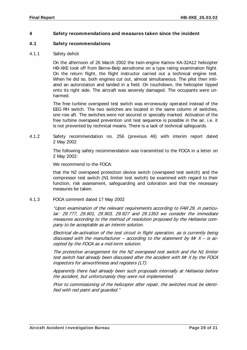
4.1.1 Safety deficit
On the afternoon of 26 March 2002 the twin-engine Kamov KA-32A12 helicopter HB-XKE took off from Berne-Belp aerodrome on a type rating examination flight. On the return flight, the flight instructor carried out a technical engine test. When he did so, both engines cut out, almost simultaneous. The pilot then initi-ated an autorotation and landed in a field. On touchdown, the helicopter tipped onto its right side. The aircraft was severely damaged. The occupants were un-harmed.
The free turbine overspeed test switch was erroneously operated instead of the EEG RH switch. The two switches are located in the same column of switches, one row aft. The switches were not secured or specially marked. Activation of the free turbine overspeed prevention unit test sequence is possible in the air, i.e. it is not prevented by technical means. There is a lack of technical safeguards.
4.1.2 Safety recommendation no. 256 (previous 46) with interim report dated 2 May 2002
The following safety recommendation was transmitted to the FOCA in a letter on 2 May 2002:
We recommend to the FOCA:
that the N2 overspeed protection device switch (overspeed test switch) and the compressor test switch (N1 limiter test switch) be examined with regard to their function, risk assessment, safeguarding and coloration and that the necessary measures be taken.
4.1.3 FOCA comment dated 17 May 2002
“Upon examination of the relevant requirements according to FAR 29, in particu-lar: 29.777, 29.901, 29.903, 29.927 and 29.1353 we consider the immediate measures according to the method of resolution proposed by the Heliswiss com-pany to be acceptable as an interim solution.
Electrical de-activation of the test circuit in flight operation, as is currently being discussed with the manufacturer – according to the statement by Mr X – is ac-cepted by the FOCA as a mid-term solution.
The protective arrangement for the N2 overspeed test switch and the N1 limiter test switch had already been discussed after the accident with Mr X by the FOCA inspectors for airworthiness and registers (LT).
Apparently there had already been such proposals internally at Heliswiss before the accident, but unfortunately they were not implemented.
Prior to commissioning of the helicopter after repair, the switches must be identi-fied with red paint and guarded.”
Aircraft Accident Investigation Bureau Page 28 of 31
Final Report HB-XKE_26.03.02
4.1.4 Safety recommendation no. 256 to the European Aviation Safety Authority EASA
The Swiss AAIB makes the application, that the free turbine overspeed test switch and the gas generator test switch in relation to their function, risk analy-sis, safety device and colouring have to be verified and the necessary measures have to be taken.
In particular it has to be guaranteed technically, that an unintentional activation of these test sequences is not possible during flight.
4.2 Measures taken since the accident
4.2.1 Interim modifications of the switches by Heliswiss AG
To date, the helicopter manufacturer has only, by means of a drawing, recom-mended to mark the test switches in yellow-black colour. Further measures have not been made.
The keeper has marked and protected the gas generator test switch and the free turbine overspeed test switch (see Annex 2).
Berne, 9 September 2008 Aircraft Accident Investigation Bureau
This report contains the AAIB’s conclusions on the circumstances and causes of the accident which is the subject of the investigation.
In accordance with Annex 13 of the Convention on International Civil Aviation of 7 December 1944 and article 24 of the Federal Air Navigation Law, the sole purpose of the investigation of an aircraft accident or serious incident is to prevent future accidents or serious incidents. The legal assessment of accident/incident causes and circumstances is expressly no concern of the accident investigation. It is therefore not the purpose of this investigation to determine blame or clarify questions of liability.
If this report is used for purposes other than accident prevention, due consideration shall be given to this circumstance.
Aircraft Accident Investigation Bureau Page 29 of 31
Final Report HB-XKE_26.03.02
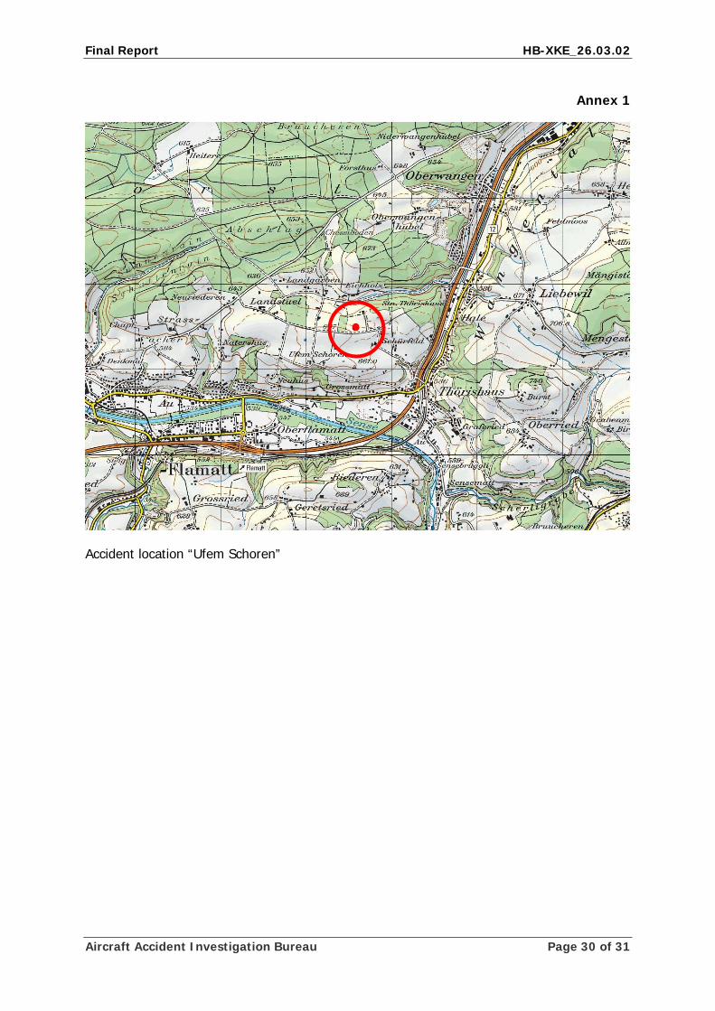
Annex 1
Accident location “Ufem Schoren”
Aircraft Accident Investigation Bureau Page 30 of 31
Final Report HB-XKE_26.03.02
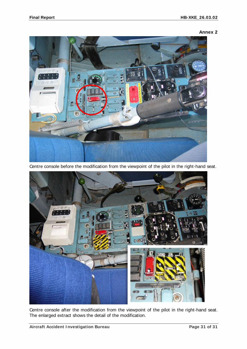
Annex 2
Centre console before the modification from the viewpoint of the pilot in the right-hand seat.
Centre console after the modification from the viewpoint of the pilot in the right-hand seat. The enlarged extract shows the detail of the modification.
Aircraft Accident Investigation Bureau Page 31 of 31

![11-Rotor hubs 2013 [Modo de Compatibilidade] · • Helicopter blades are attached to the rotor shaft with a ... Kamov Ka-29TB Helix: ... Helicopters / Filipe Szolnoky Cunha Rotor](https://img.pdfslide.us/doc/110x75/5b2acbd87f8b9a55068b9170/11-rotor-hubs-2013-modo-de-compatibilidade-helicopter-blades-are-attached.jpg)


![Lkeh{kk 2010 2011 - Mahila Umang Producers Companyumang-himalaya.com/pdf/Umang Review 2010-11.pdf · Lkeh{kk 2010 &2011 Åuh Ekfgyk meax izkSM~;lj dEiuh fyfeVsM xke uSuh] ikLV vkfQl](https://img.pdfslide.us/doc/110x75/5c882c5709d3f245798c53b0/lkehkk-2010-2011-mahila-umang-producers-companyumang-review-2010-11pdf.jpg)