Embed Size (px)
Citation preview
Exp NO. 1 DATE: 15.02.13
FOUNDATION MARKING
AIM: To make the foundation for a building on the given site.
INSTRUMENTS USED: Ranging rods
Arrows
Mallet
Tape
Cross staff rod with head
Thread ball
Dry lime powder
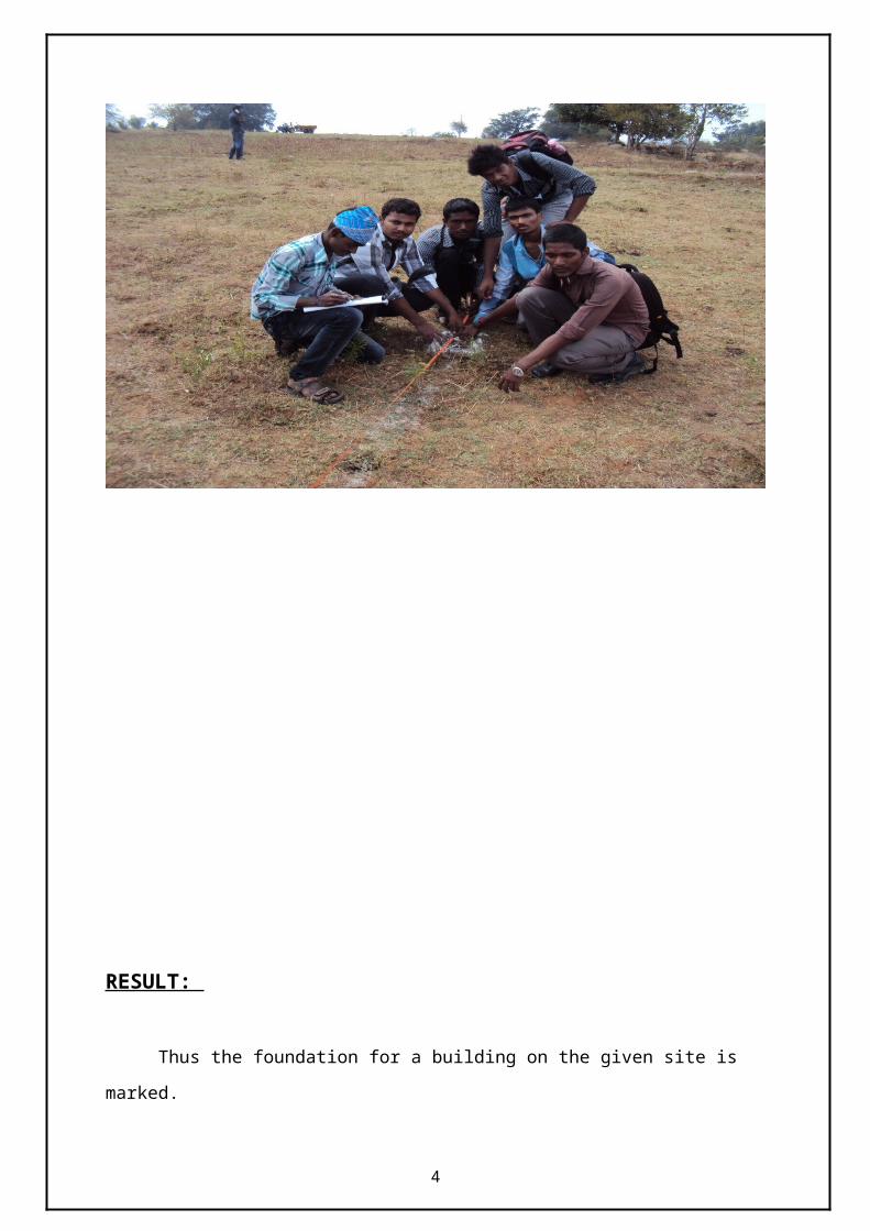
PROCEDURE: Arrows are fixed corresponding to the centre line of the layout.
Length is measured using taps and cross-staff is used to get perpendicular alignment.
Centre line is marked and the walls are marked parallel to it using thread ball and
chalk powder.
The width to be excavated is then marked.
1
FOUNDATION MARKING
2
RESULT:
Thus the foundation for a building on the given site is marked.
Exp NO:2 DATE:15.02.13
3
ESTIMATION OF AREA OF THE FIELD BY
CHAIN SURVEYING METHOD
AIM:To conduct the chain surveying for a closed traverse and hence compare area
bounded between closed traverse.
INSTRUMENTS REQUIRED:
Chain (30m or 20m)
Ranging rods
Cross staff
Tape
PROCEDURE:
Select any random line free from obstacle.
Locate the foot of the perpendicular (B1) from the point B on the random
line AB1.
Establish intermediate points C1, D1, etc., in line with AB1 by direct
ranging.
Erect perpendiculars at C1, D1, etc., on the random line to meet the line
AB.
Measure the lengths AC1, AD1, AB1, etc., and the perpendicular distance
BB1.
Compute the perpendicular distances C1C, D1D, etc., from the similarity
of triangles.
Mark distances C1C and D1D etc., on the erected perpendiculars and
locate the points C, D, etc., on the line AB.
Now A, C, D and B are in a straight line
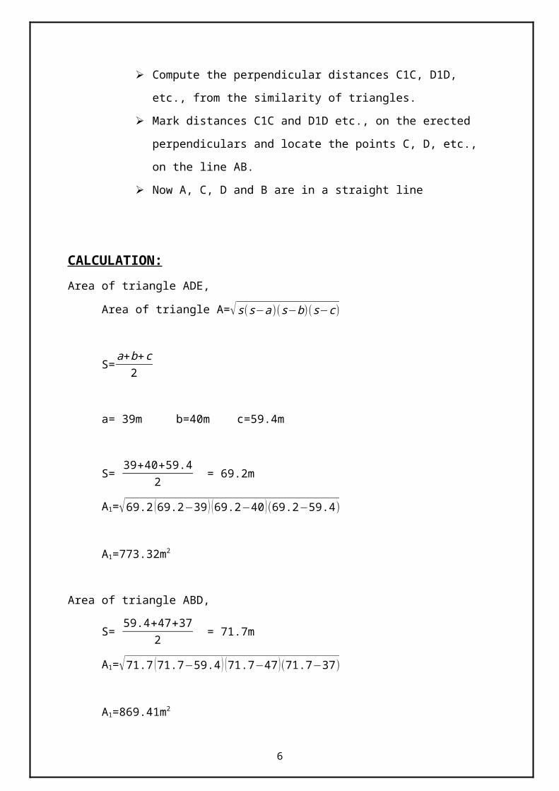
CALCULATION:4
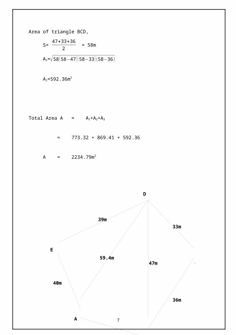
Area of triangle ADE,
Area of triangle A=√s (s−a)(s−b)(s−c )
S=a+b+c
2
a= 39m b=40m c=59.4m
S= 39+40+59.4
2 = 69.2m
A1=√69.2 (69.2−39 ) (69.2−40 )(69.2−59.4)
A1=773.32m2
Area of triangle ABD,
S= 59.4+47+37
2 = 71.7m
A1=√71.7 (71.7−59.4 ) (71.7−47 )(71.7−37)
A1=869.41m2
Area of triangle BCD,
S= 47+33+36
2 = 58m
A1=√58 (58−47 ) (58−33 )(58−36)
A1=592.36m2
Total Area A = A1+A2+A3
= 773.32 + 869.41 + 592.36
A = 2234.79m2
5
RESULT:
The total area of the given closed traverse is 2234.79 m 2
6
E
A
B
C
D
33m
47m59.4m
39m
36m
37m
40m
Exp No.3 DATE:16.02.13
COMPASS TRAVERSING
AIM:
To traverse around the gives ABCDE polygon with using prismatic compass and plot a
traverse with the suitable scale.
INSTRUMENT USED:
1. Prismatic compass
2. Tripod
3. Ranging rods
4. Tape
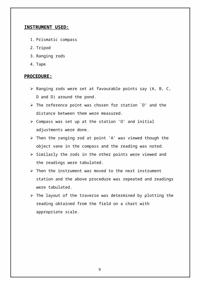
PROCEDURE:
Ranging rods were set at favourable points say (A, B, C, D and D) around the pond.
The reference point was chosen for station `O’ and the distance between them were
measured.
Compass was set up at the station ‘O’ and initial adjustments were done.
Then the ranging rod at point ‘A’ was viewed though the object vane in the compass
and the reading was noted.
Similarly the rods in the other points were viewed and the readings were tabulated.
Then the instrument was moved to the next instrument station and the above
procedure was repeated and readings were tabulated.
The layout of the traverse was determined by plotting the reading obtained from the
field on a chart with appropriate scale.
7
TABULATION:
SL.
NOLINE
BACK
BEARING
FORE
BEARINGIA=BB-FB
INCLUDED
ANGLE
1. AB 130°30’ 310°30’ 255°30’- 130°30’ 125°00’
2. BC 222°30’ 42°30’ 310°30’- 222°30’ 88°00’
3. CD 268°30’ 88°00’(42°30’- 268°30’)
+360°134°30’
4. DE 351°00’ 171°00’(88°00’- 351°00’)
+360°97°00’
5. EA 255°30’ 255°30’ 171°00’- 75°30’ 95°30’
8
A
B
C
D
E
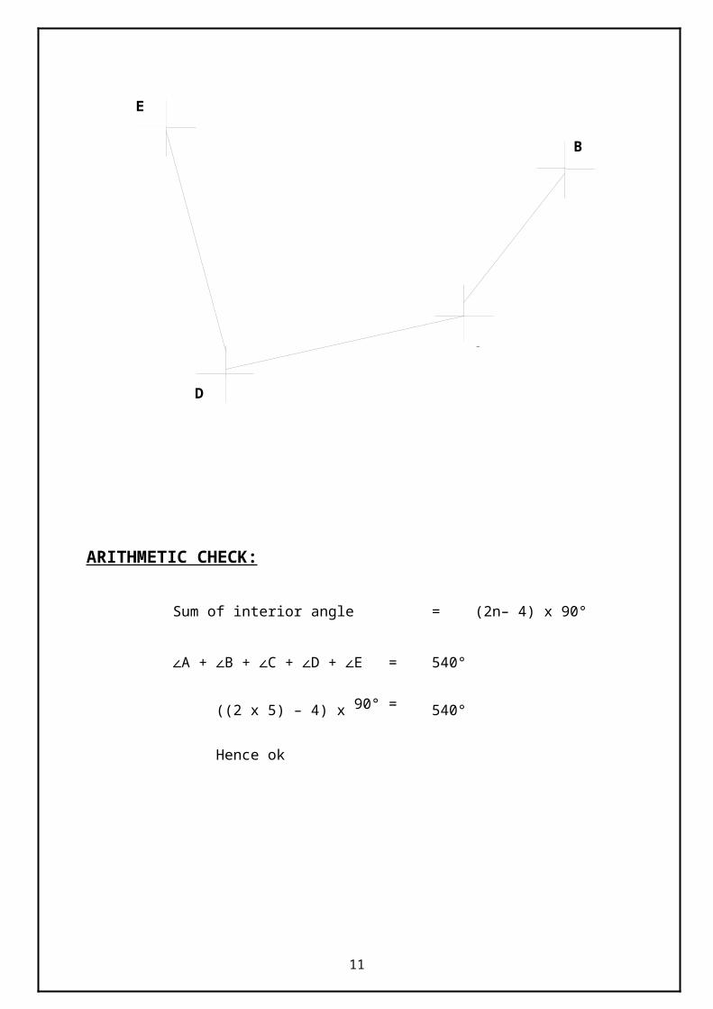
ARITHMETIC CHECK:
Sum of interior angle = (2n– 4) x 90°
∠A + ∠B + ∠C + ∠D + ∠E = 540°
((2 x 5) – 4) x 90° = 540°
Hence ok
RESULT:
The angle of surface is found as,
∠A =125°00’
∠B =88 °00’
∠C = 134°30’
∠D =97°00’
9

∠E =95°30’
Exp NO. 4 DATE:16.02.13
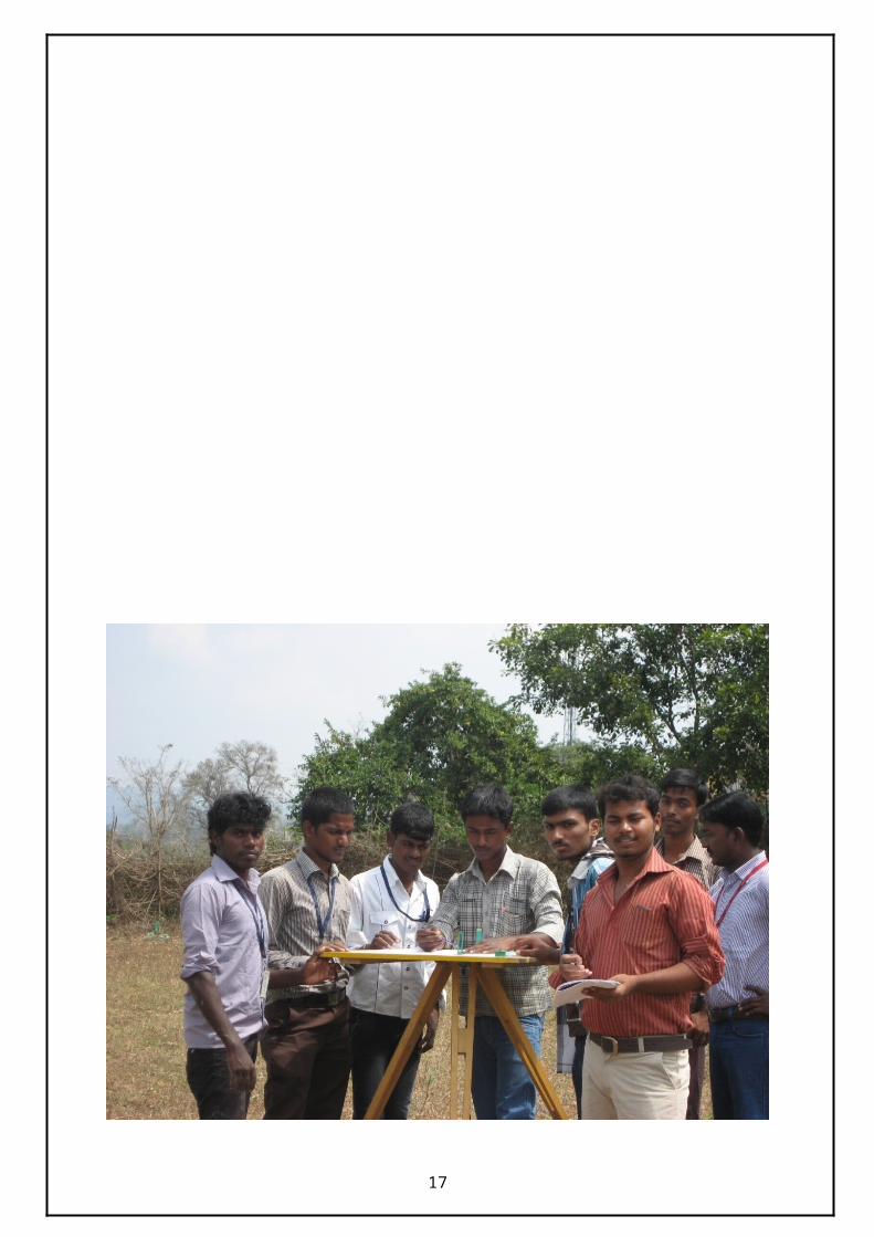
PLANE TABLE SURVEYING
AIM: To determine the area of the plot (ABCDEFA) by traversing method using plane
table.
INSTRUMENTS REQUIRED:
1. Plane table with tripod
2. Alidade
3. Plumbing fork and plumb bob
4. Sprit level
5. Trough Compass
6. Drawing sheet
PROCEDURE:
Consider a fairly level ground and mark the points A, B, C, D, E&F to form
closed traverse.
Set the table at A and do initial adjustments. Use plumbing fork for traversing A
with the help of trough compass.
With the alidade pivoted about A, sight it to B and draw the ray. Measure AB and
scale off ‘AB’ to suitable scale. Similarly, draw a ray towards F, measure AF and
plot ‘F’.
Shift the table to the B and do initial adjustment Orient the table accurately by
back sighting A. clamp the table.
10
Pivoting the alidade about ‘b’ sights to C. measure BC and plot it on the drawn
ray to the same scale. Similarly, the table can set at other stations and traverse is
completed.
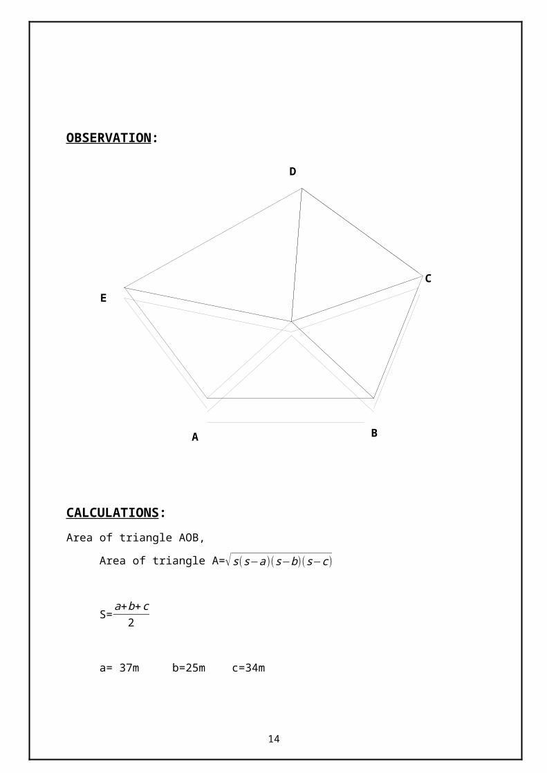
OBSERVATION:
CALCULATIONS:Area of triangle AOB,
Area of triangle A=√s (s−a)(s−b)(s−c )
S=a+b+c
2
a= 37m b=25m c=34m
11
E
A B
C
D
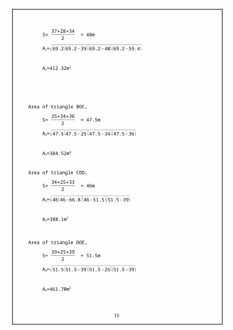
S= 37+28+34
2 = 48m
A1=√69.2 (69.2−39 ) (69.2−40 )(69.2−59.4)
A1=412.32m2
Area of triangle BOC,
S= 25+34+36
2 = 47.5m
A2=√47.5 (47.5−25 ) (47.5−34 )(47.5−36)
A2=384.52m2
Area of triangle COD,
S= 34+25+33
2 = 46m
A3=√46 ( 46−66.8 ) ( 46−51.5 )(51.5−39)
A3=388.1m2
Area of triangle DOE,
S= 39+25+39
2 = 51.5m
A4=√51.5 (51.5−39 ) (51.5−25 )(51.5−39)
A4=461.70m2
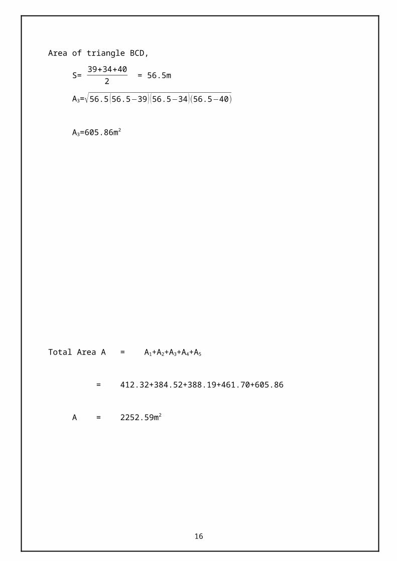
Area of triangle BCD,
S= 39+34+40
2 = 56.5m
A3=√56.5 (56.5−39 ) (56.5−34 )(56.5−40)
12
A3=605.86m2
Total Area A = A1+A2+A3+A4+A5
= 412.32+384.52+388.19+461.70+605.86
A = 2252.59m2
13
14
RESULT:
The area of the plot using plane table surveying by radiation method = 2252.59m2.
Exp NO. 5 DATE:18.02.13
SPOT LEVELLING
AIM: To determine the R.L. of the particular plot by spot levelling.
INSTRUMENTS REQUIRED:
1. Dumpy level
2. Chain (20m or 30m)
3. Levelling staff
4. Tape
5. Ranging rods
6. Pegs or arrows
7. Tripod
FIELD PROCEDURE:
Mark the area of the plot 30x16 with the help of chain & tape.
Fix the ranging rods at the ends and see that the plot is perfectly a rectangle.
Make grids of size 5m x 3.2m.
Place the instrument & fix it at the place, which covers the maximum points on the
plot.
Take the benchmark and note it down in back sight.
15
Using levelling staffs take all the readings, which are marked at 3.2m & 5m intervals
and note it down in the intermediate sight.
Repeat the process and take all the readings on all points.
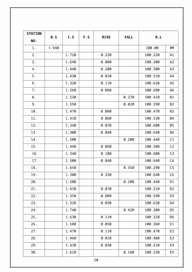
Tabulate all the readings that are taken properly.
STATION
NO.B.S I.S F.S RISE FALL R.L
1. 1.940 100.00 BM
2. 1.720 0.220 100.220 A1
3. 1.640 0.080 100.300 A2
4. 1.440 0.200 100.500 A3
5. 1.430 0.010 100.510 A4
6. 1.320 0.110 100.620 A5
7. 1.260 0.060 100.680 A6
8. 1.530 0.270 100.410 B1
9. 1.550 0.020 100.390 B2
10. 1.470 0.080 100.470 B3
11. 1.410 0.060 100.530 B4
12. 1.340 0.070 100.600 B5
13. 1.300 0.040 100.640 B6
14. 1.500 0.200 100.440 C1
15. 1.440 0.060 100.500 C2
16 1.340 0.100 100.600 C3
.17. 1.300 0.040 100.640 C4
18. 1.650 0.350 100.290 C5
19. 1.300 0.350 100.640 C6
20. 1.500 0.200 100.440 D1
21. 1.430 0.070 100.510 D2
22. 1.350 0.080 100.590 D3
23. 1.320 0.030 100.620 D4
24. 1.740 0.420 100.200 D5
25. 1.630 0.110 100.310 D6
26. 1.580 0.050 100.360 E1
16
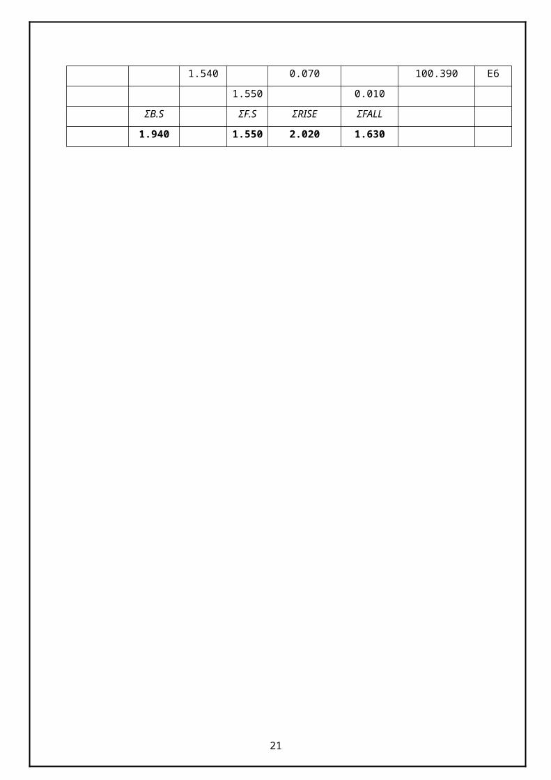
27. 1.470 0.110 100.470 E2
28. 1.460 0.010 100.480 E3
29. 1.430 0.030 100.510 E4
30. 1.610 0.180 100.330 E5
1.540 0.070 100.390 E6
1.550 0.010
ΣB.S ΣF.S ΣRISE ΣFALL
1.940 1.550 2.020 1.630
17
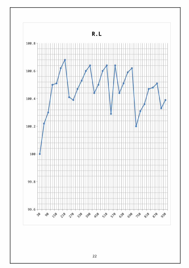
30 90150
210270
330390
450510
570630
690750
810870
93099.6
99.8
100
100.2
100.4
100.6
100.8
R.L
18
RESULT:
The R.L of the particular plot is found out by spot levelling method.
Exp NO.6 DATE:19.02.13
19
SETTING OUT AN CIRCULAR CURVEAIM:
To set a circular curve on the given field using double theodolite method.
INSTRUMENTS USED:1. Theodolite
2. Thread ball
3. Tape
4. Ranging rod
5. Cross staff
6. Arrows
7. Mallet
8. Chalk powder
PRINCIPLE:A circular curve could be set out by the following methods:
1. Rankin method of tangential angle
2. Double theodolite method
3. Tachometric method
FORMULA USED: Deflection angle = 1718.9 (C/R)
Length of the curve = R /180
Where,
R- Radius of the curve
C- Length of the curve
20
PROCEDURE: An open ground, which was almost level, was given for laying out of given
curves.
Various instruments like theodolite, levelling staff, tape, ranging rod and
peg were used to set the curve. The deflection angle, tangential angle, chain
age, stadia intercept were calculated beforehand from the formulae.
Based on the results from the calculated data was set on the field by double
theodolite method.
The tangent point was located and two theodolites were set there. The line
of sight was directed to the intersection point and the Varnier reading was
set zero. Varnier reading was set to first deflection angle and point of
intersection of line of sight was locate using thread and ranging rod and the
first peg was fixed.
The procedure is repeated for various angles and the curve is set out.
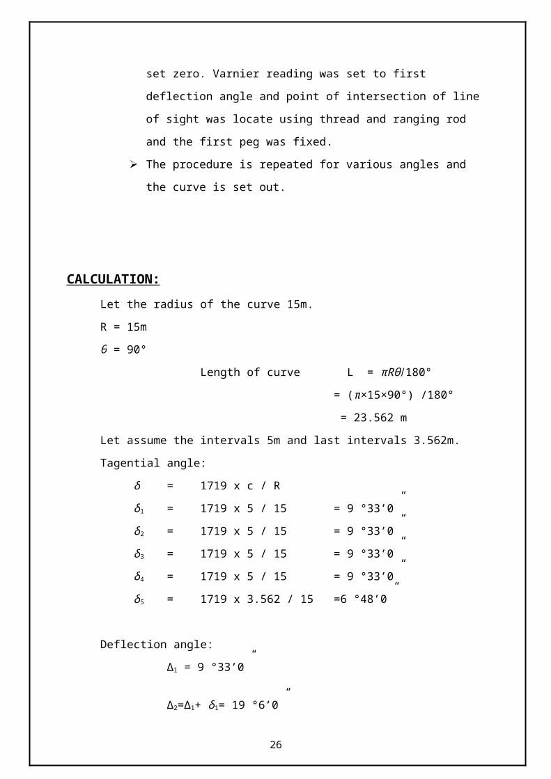
CALCULATION:Let the radius of the curve 15m.
R = 15m
θ = 90°
Length of curve L = πRθ /180°
= (π×15×90°) /180°
= 23.562 m
Let assume the intervals 5m and last intervals 3.562m.
Tagential angle:
δ = 1719 x c / R
δ 1 = 1719 x 5 / 15 = 9 °33’0”
δ 2 = 1719 x 5 / 15 = 9 °33’0”
δ 3 = 1719 x 5 / 15 = 9 °33’0”
δ 4 = 1719 x 5 / 15 = 9 °33’0”
δ 5 = 1719 x 3.562 / 15 =6 °48’0”
Deflection angle:21
∆1 = 9 °33’0”
∆2=∆1+ δ 1= 19 °6’0”
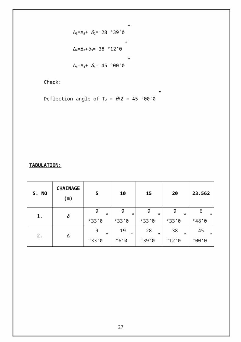
∆3=∆2+ δ 2= 28 °39’0”
∆4=∆3+δ3= 38 °12’0”
∆5=∆4+ δ 4= 45 °00’0”
Check:
Deflection angle of T2 = θ /2 = 45 °00’0”
TABULATION:
S. NOCHAINAGE
(m)5 10 15 20 23.562
1. δ 9 °33’0” 9 °33’0” 9 °33’0” 9 °33’0” 6 °48’0”
2. ∆ 9 °33’0” 19 °6’0” 28 °39’0” 38 °12’0” 45 °00’0”
22

23
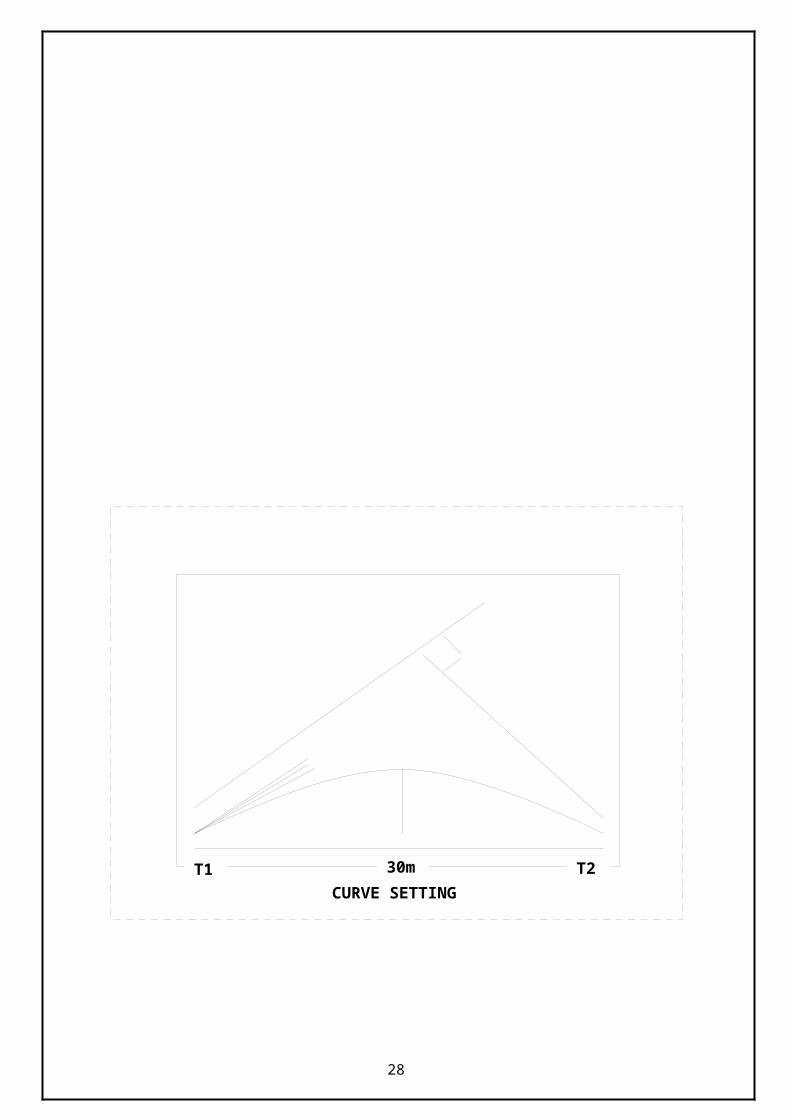
T1 T230mCURVE SETTING
RESULT:
Hence the circular curve was set out using double theodolite method.
Exp NO.7 DATE:20.02.13
24
TACHOMETRIC CONTOURING OF HILL LOCKAIM:
To draw the contour map of the given area.
INSTRUMENTS REQUIRED:
Theodolite
Tape (or) chain
Levelling staff.
Ranging rods
Pegs (or) arrows
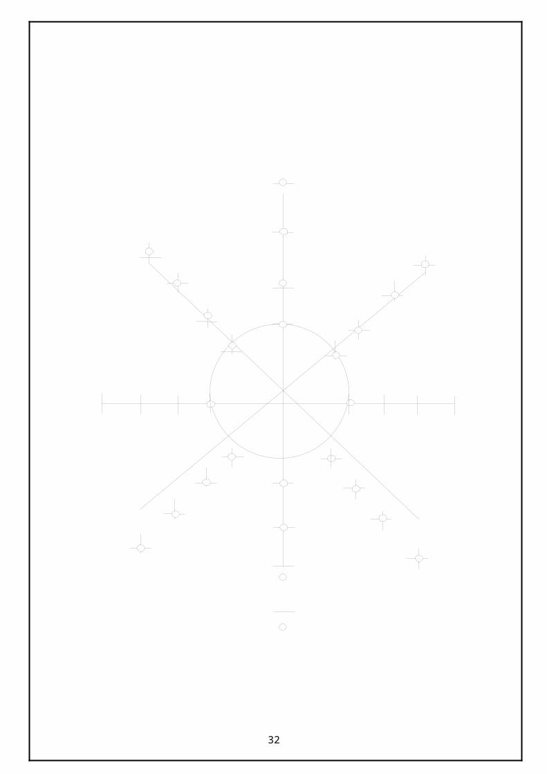
PROCEDURE: Select a point “O” as the instrument station.
The Instrument is fixed and the preliminary adjustments are made.
The telescope is kept at 0-0 in the horizontal scale and focusing the ranging rod at
the point A.
Then the staff is kept at a point OA1, the top, middle and bottom readings and
vertical angles are noted. Readings are taken at any number of possible intervals.
When the staff reading of the line OA is over than the telescope is moved at an
angle of 60° to focus the ranging rod at B.
Similarly the staff reading on the line OB is taken.
This is repeated up to 360° and the calculations are made to find the elevation.
25
26
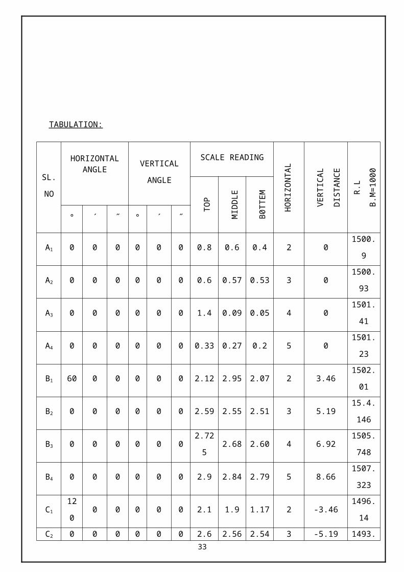
TABULATION:
SL.
NO
HORIZONTAL ANGLE VERTICAL
ANGLE
SCALE READING
HO
RIZ
ON
TAL
DIS
TAN
CE
VER
TIC
AL
DIS
TAN
CE
R.L
B.M
=100
0
TOP
MID
DLE
B0T
TEM
° ´ ˝ ° ´ ˝
A1 0 0 0 0 0 0 0.8 0.6 0.4 2 0 1500.9
A2 0 0 0 0 0 0 0.6 0.57 0.53 3 01500.9
3
A3 0 0 0 0 0 0 1.4 0.09 0.05 4 01501.4
1
A4 0 0 0 0 0 0 0.33 0.27 0.2 5 01501.2
3
B1 60 0 0 0 0 0 2.12 2.95 2.07 2 3.461502.0
1
B2 0 0 0 0 0 0 2.59 2.55 2.51 3 5.1915.4.14
6
B3 0 0 0 0 0 0 2.725 2.68 2.60 4 6.921505.7
48
B4 0 0 0 0 0 0 2.9 2.84 2.79 5 8.661507.3
23
C1 120 0 0 0 0 0 2.1 1.9 1.17 2 -3.461496.1
4
C2 0 0 0 0 0 0 2.6 2.56 2.54 3 -5.191493.7
44
27
C3 0 0 0 0 0 0 3.47 3.43 3.4 4 -6.921491.1
42
C4 0 0 0 0 0 0 3.7 3.65 3.6 5 -8.661489.1
9
D1 180 0 0 0 0 0 1.59 1.57 1.56 2 01499.9
25
D2 0 0 0 0 0 0 1.755 1.73 1.71 3 01499.7
7
D3 0 0 0 0 0 0 2.7 2.66 2.64 4 01498.8
4
D4 0 0 0 0 0 0 3.31 3.37 3.22 5 01498.1
3
E1 240 0 0 0 0 0 0.83 0.8 0.77 2 3.461504.1
6
E2 0 0 0 0 0 0 0.73 0.68 0.63 3 5.191506.0
16
E3 0 0 0 0 0 0 1.15 1.07 1.00 4 6.921507.3
58
E4 0 0 0 0 0 0 1.2 1.1 1.00 5 8.661509.0
6
F1 360 0 0 0 0 0 0.595 0.56 0.54 2 -3.461497.4
75
F2 0 0 0 0 0 0 0.185 0.14 0.1 3 -5.191496.1
62
F3 0 0 0 0 0 0 0.19 0.14 0.00 4 -6.921494.4
32
28

RESULT:
Thus the contour of the given hill lock was drawn.
29
Exp NO.8 DATE:21.02.13
HILL HEIGHT
AIM: To find the heights and distance of the object using single plane method the foot of
the object being inaccessible.
INSTRUMENT REQUIRED: Theodolite
Tripod
Levelling Staff
PROCEDURE: Set up the Theodolite at O level it accurately with respect to the altitude bubble.
Direct the telescope towards the top of the object Q and bisect it accurately. Clamp
both the plates. Read the vertical angle (α1).
Transit the telescope so that the line of sight is reversed. Mark the second instrument
station R on the ground. Measure the distance the distance OR accurately. Repeat
steps 2 and 3 for both face observations. The mean values should be adopted. Station
R should be almost at the level as station O.
With the vertical set to zero reading in the staff kept at the near by B.M.
Shift the instrument to R and set up the Theodolite. Measure the vertical angle α2 to Q
with both face observations.
With the vertical vernier set to zero reading and the altitude bubble in the centre of its
run, take the reading on the staff kept at the near by B.M.
30
FORMULA USED:
D = K s + C (without inclination)
D = K scos2θ + Csinθ
D = K s (sin2 θ/2 +C sinθ
R.L. = B.M. + h + V – R (angle of elevation)
R.L. = B.M. + h - V – R (angle of depression)
Where,
R - Central hair reading
h - Height of the instrument
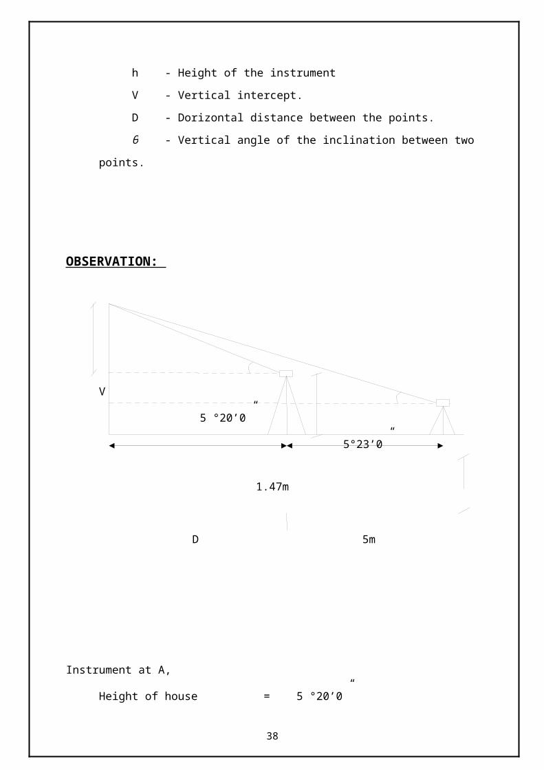
V - Vertical intercept.
D - Dorizontal distance between the points.
θ - Vertical angle of the inclination between two points.
OBSERVATION:
V
5 °20’0”
5°23’0”
1.47m
D 5m
31
Instrument at A,
Height of house = 5 °20’0”
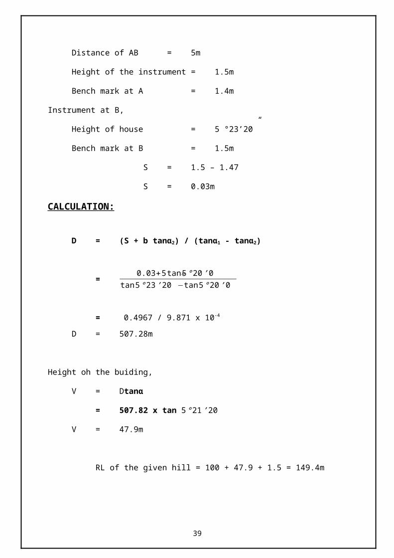
Distance of AB = 5m
Height of the instrument = 1.5m
Bench mark at A = 1.4m
Instrument at B,
Height of house = 5 °23’20”
Bench mark at B = 1.5m
S = 1.5 – 1.47
S = 0.03m
CALCULATION:
D = (S + b tanα2) / (tanα1 - tanα2)
=0.03+5 tan5 ° 20’ 0”
tan 5 °23 ’20 ”−tan 5 °20 ’0 ”
= 0.4967 / 9.871 x 10⁻⁴
D = 507.28m
Height oh the buiding,
V = Dtanα
= 507.82 x tan 5 °21 ’20”
V = 47.9m
RL of the given hill = 100 + 47.9 + 1.5 = 149.4m
32
RESULT:
Thus the distance between the hill and BM is found to be 507.82m
The reducxed level of the hill found to be 49.4m.
33
Exp NO.9 DATE:22.02.13
SETTING OUT OF A BUILDING
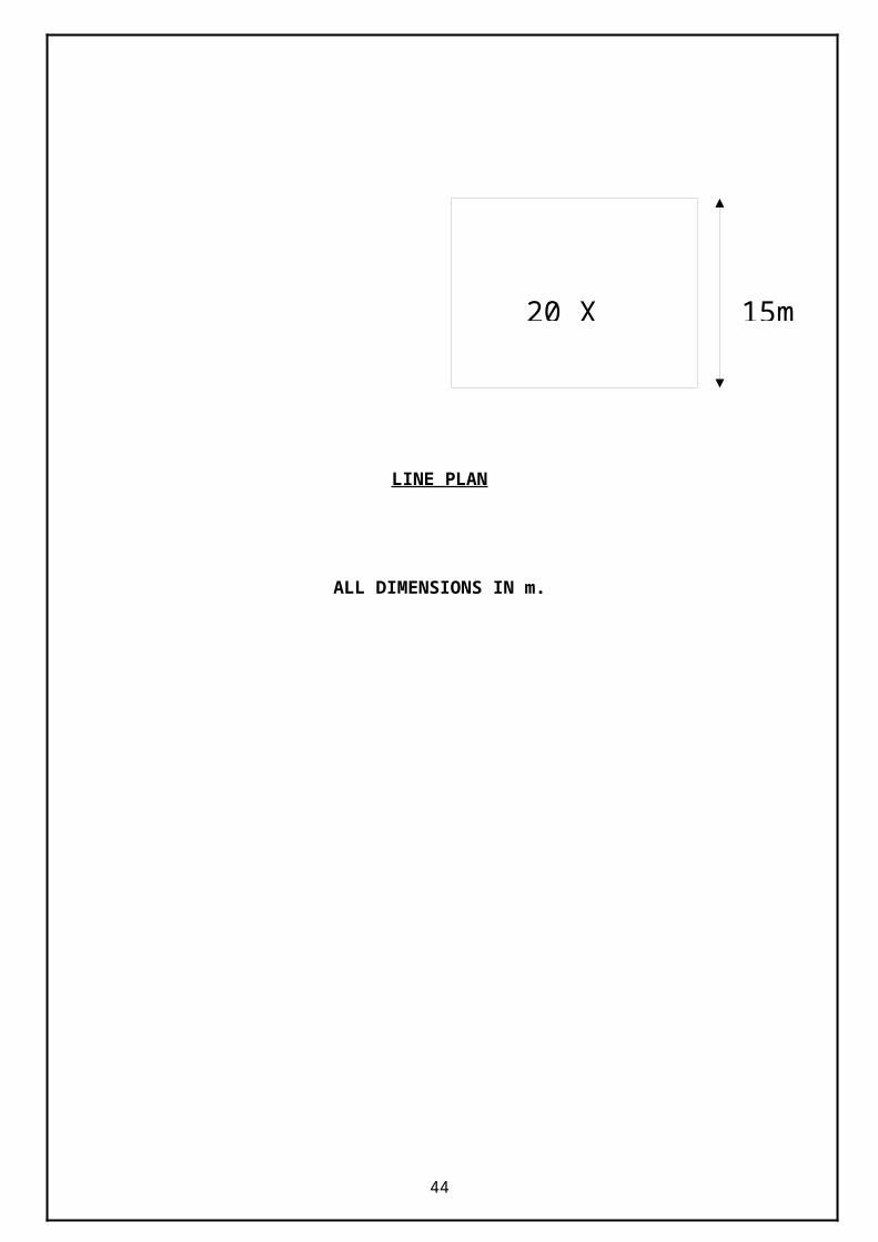
AIM:To mark the centre line of a framed structure building plan on the ground.
INSTRUMENTS REQUIRED:
Chain (or) tape
Cross staff (or) theodolite
Rope
Arrows (or) pegs
Lime powder
PROCEDURE:
Erect a peg at the point 1 and tie one end of the thread.
Taking the remaining portion of the thread upto the peg 2 and tie the
thread with peg 2. Like that bring remaining portion of the thread through
the points 3 and 4.
Now set 90º at q where the threads are intersected. (by the help of inner
sketch.) Make sure that the distance between P and Q is equal to the centre
to centre distance of outside shorter walls.Tie the thread with the peg 4.
By following the above steps set 90º at R,S and P. Make sure that the
distance QR=15m, RS=30m and SP=15m.
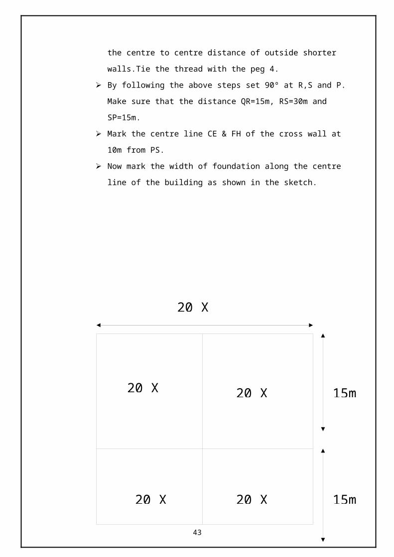
Mark the centre line CE & FH of the cross wall at 10m from PS.
Now mark the width of foundation along the centre line of the building as
shown in the sketch.
34
LINE PLAN
ALL DIMENSIONS IN m.
35
20 X 15
20 X 15
20 X 15 20 X 15
20 X 15
20 X 2
15m
15m
15m
RESULT: Setting out of building is completed.
36
Exp NO.10 DATE:23.02.13
TOTAL STATION
AIM:
To study about the electronic distance measurement and total station.
INTRODUCTION:
This document will describe the basic operation and application of the Leica Total
Station surveying equipment as well as discuss the process of downloading the data and
producing detailed topography maps using the Liscad software. It is meant to explain the
operation based upon the Active Tectonics members’ experiences in using the equipment,
and should supplement the reading of the manual and your intuition. This document contains
the basic set-up and operating instructions for our electronic surveying equipment. It also
contains discussions of how the instrument works, and suggestions for methods and strategies
of use.
INSTRUMENTS:
Total station
Reflector
Plumbing pole/reflector staff
Tripod for Theodolite
Small Internal Batteries
Cables
Portable Power Inverter
International Adapter Plugs
Verbatim SRAM Card 2MB
2-Way Radios
PLANNING AND RECONNAISSANCE:
Before leaving the office, look at the base map or airphoto of the area and define the
mapping project(s). Consider access. If you need permission to get on the property, you
should get that well in advance. The equipment is heavy and bulky. Two people can carry it
37
with difficulty for 1 or 2 kilometers, but it is a demoralizing experience. Therefore, try to plan
appropriate vehicle access, but don't drive unnecessarily through the landscape destroying the
beauty and making a bad name for geologists! You must have a field assistant. Operating this
equipment by yourself is pretty silly, although it can be done. You will end up walking at
least two times the total slope length of the shots you make. The distance will add up quickly!
Your helper need not be a geologist, but should be sturdy, careful, and interested.
Once in the field, walk over the area with the field assistant. Look for suitable instrument
stations. Much time and precision may be lost with multiple set ups. Therefore, plan the
minimum number of instrument stations. A high position somewhere near the survey area
should suffice. Remember that the instrument has an effective working range of at least 1 km,
so if you have walkie-talkies or body signals and can communicate (see communication
techniques) over long ranges, much of the survey may be completed from a single well
chosen site. Consider gullies and ridges, and other obstacles that may obscure the survey.
Remember that the reflector plumb staff telescopes to 2.15 m, so that may help with
visibility. Be sure to communicate to the instrument operator changes in reflector height
(click here to see how to enter into Total Station) and record them on the Survey Record
Form and in the Thoedolite! While reconnoitering the area, consider the problem being
addressed by the mapping project, and choose an appropriate and optimal strategy: What is
the optimum number and distribution of points necessary for this project? What is the desired
precision? Will I ever want to reoccupy this network? Be sure that the field assistant
understands the strategy too, so that you do not have to have major discussions about strategy
once you have started working, although the plan should be flexible if an obvious
modification becomes apparent.
SET-UP:
Choose an adequate instrument station as described above. In detail, ensure that you
can safely operate the instrument without knocking it over. It is necessary to have the center
of the instrument, which is the point of intersection of the transverse axis and the vertical axis
of the instrument, directly over a given point on the ground (the Instrument Station). Also, the
circle and the transverse axis must be horizontal (Moffitt, 1987). Remove the yellow plastic
cap from the tripod, and leave the instrument in the case until the tripod is nearly level (see
below). The tripod legs are spread (not too vertical) and their points are placed so that the
tripod is approximately horizontal and the telescope is at a convenient height for sighting
(this is important: you don't want to get a sore back from it being too low, nor do you want to
38
get sore calves and fall over from it being too high). The instrument should be within 20 cm
of the desired point, but no extra care is taken to set it up closely at once. If the location of the
instrument station is not predetermined, set up first, and then use the optical plummet to
locate the benchmark: this will save time, because it takes extra care to accurately set up over
a benchmark. When setting up on rough ground, two legs of the tripod should be set at about
the same elevation and the top of the tripod is made level by changing the length of the third.
Consider the common sighting direction and try to have one leg pointing that way so that
there will be a gap between two legs behind, and the instrument operator will not have to
straddle a tripod leg for the entire session. If the instrument is more than a few inches from
the given point, the tripod is shifted bodily without changing the inclination of the legs and it
is set near as possible to the point. Check the level by placing a Brunton compass on top of
the tripod and adjusting gently until the Brunton bubble level indicates that the top of the
tripod is level. Tread tripod shoes firmly into the ground, making sure to press along the leg
and not verically down (Anderson and Mikhail, 1989). If shoes do not penetrate to an equal
depth, re-level by extending or retracting the tripod legs. Before attaching the instrument,
check that the clamps of the telescopic legs are tight.
Once the tripod is nearly level and nearly above the desired point, remove the Theodolite
gently from its case and carry it with one hand on the upper handle, and one hand below, to
the top of the tripod, and immediately screw the tripod fixing screw firmly into the bottom of
the theodolite. The levels on the instrument are very sensitive, and therefore, the instrument
should be completely set up in order to ensure that it will be properly leveled. This will also
give the tripod more time to thermally equilibrate with the atmosphere and incident sunlight,
since differential thermal expansion of the tripod legs will effect the levels. Now you are
ready for fine leveling of the instrument. Use the three black footscrews on the tribrach (the
device on the bottom of the Theodolite to which the tripod fixing screw is attached) to center
the circular bubble. This is a coarse level. Turn the outer ring on the eyepiece of the optical
plummet until the crosshairs are in focus. Turn the inner ring of the optical plummet until the
ground point is in focus. Slacken tripod fixing screw and move instrument over tripod plate
until cross hairs coincide with ground mark. Only translate the instrument over the tripod
plate, do not rotate it. Finally retighten fixing screw. Now do the fine leveling.
39

FINE LEVELING INSTRUCTIONS:
1) Set plate level (the one in the tube--this is the fine level) parallel to two
footscrews. Center plate level bubble by adjusting these two screws in equal
and opposite directions.
2) Turn Theodolite through 90°. Center bubble with third footscrew.
3) Turn Theodolite through 180° (in the same direction as above). Note
position of bubble. Turn the third footscrew (same one used in step 2) to bring
the bubble to a point halfway between the position noted and the centered
position. Use the adjusting pin (in silver handle in the Theodolite case) to turn
the adjustment screw until bubble is centered (see page 44 of the Theodolite
manual for a picture).
4) Repeat until bubble remains centered within a single division for any
position.
Note that the instrument will drift out of level as the day progresses. Repeat the above steps
as needed and enter change by pressing the level button (see Operation). If the optical
plummet is not above the ground point desired, slacken tripod fixing screw and move
instrument over tripod plate until cross hairs coincide with ground mark. Only translate the
instrument over the tripod plate, do not rotate. Retighten fixing screw. Now press the ON
button and the startup menu will come on. Press the white LEVEL (figure 1) key along the
bottom of the key panel followed by continue. When the levels are set press the continue
button.
Now that the instrument is leveled up, set up and test the electronics. First, insert the
Verbatim SRAM card into the slot in the Theodolite. Ensure that the arrow on the back of the
card faces down when you insert it. See below for a suggested initial key sequence for the
Theodolite and see the TPS-System 1000 Short Instructions System manual in the Theodolite
case for a list of commands for the Theodolite. The keypad on the Theodolite allows for
maximum utility with the minimum number of keys. Therefore, most of the keys have several
40

functions, depending upon the class of operation. One way to remember the meaning is by
noting the background color of the keys.
FUNCTIONS:
Class of operation Key color Example
Fixed Keys White Functions which are always available.
Returns to last diologue. ON OFF.
Function Keys Orange These keys correspond to the bottom line
on the display. Pressing SHIFT followed
by an F key displays other options.
Navigation Keys Green Vertical scrolling, position the cursor to
edit, insert or delete numerical data and
characters, and position colums.
Numeric Keys Yellow 1...9 Numerical input. ". " and +/- set
decimal place and sign. The Enter key to
complete the data input of confirm a
selection out of a data list. Use the CE
key to delete the last entered digit or
character.
41
The ENTER button is important in that it executes the preceding commands or
answers in the affirmative, while the CE button often clears the last command. Before
anything, start with a fresh copy of the Survey Record Form, and fill out the important details
at the top. Use this form to take notes while surveying. Remember to record all observations
and considerations, since the next time you look at this data, it might 6 months from now in
the Dungeon! Record the observations so that someone else can understand. After all,
someone else might use the data.
COMMAND SEQUENCE:
S.
NO
Key sequence Description
1
Switches Theodolite on. Screen briefly displays software
version.
2
After the bubble is level press the Continue button. You can
check and adjust level all day.
3
Select the setup file by pressing F5 (Setup) and using the
arrows to select file. Press F6 to get the list of files. Push enter
to select (button with curved stem). It is also possible to set
user templates based on many different users or survey types
42
with different needs. We will go through the template setup
later in the sequence. Press Continue to go to the SETUP/
STATION DATA menu.
4 x 4
Enter the station number (is it your first one of the network?,
or is it a new station setup within a network?). Use the down
button and enter instrument height. You measure this using the
reflector staff and holding it parallel with the station and up to
the small hole (1 mm diameter) under the Leica name on the
right side of the Total Station. Arrow down and enter station
easting (we use 1000), station northing (we use 1000), and
station elevation (we use 100). Record this information on your
Survey Record Form. Make sure you are in meters, and if not,
we will go through the sequence below.
5 Press F4 to enter in the reference azimuth. Point the instrument
at the backsight or reference azimuth and input the value. For
example, 335.5 will set the reference azimuth and horizontal
circle to 335.5°. All subsequent measurements will be made
relative to that direction. Record Hz0 on the Survey Record
Form. Press continue followed by F3, record.
6
Now you are back at the main menu. Press F4, Data, to see
what is in file. Scroll down with arrows to File, selct F6 to list
files or F5 (search) to examine individual files. By using the F3
and F4 keys, you can scroll through the file history. Press
Continue when finished.
7 You should be back at the main menu. Press F3 (CONF) to
system configuration. Press enter for user configuration. Press
F4 (SET) if you need to change the language or units. Press F6
to list the selections and enter to select it. We use ENGLISH,
Metre, 3 Dec., 360 °, 3 Dec., °C, mbar, Easting/Northing,
Clockwise (+), and V-drive left. Press CONT when completed,
43
and CONT to get back to main menu.
8 ( or
)
We are going to set the user template. The first step is to set
the recording mask. From the main menu press F3 (CONF).
Press Continue. From here you can change the recording mask
sequence(F2) or the display mask (F3). Both are set in the
following sequence: Press F6 (LIST) to list the possibilites
followed by the enter key to select and move to the next
choice. When complete press CONT and set the other mask if
desired.
9 Now we are just about ready to shoot points. From Main Menu
press F6 (MEAS). Enter the reflector height by pressing F4
(TARGET) and arrow down to Refl.Height and enter in the
reflector height in meters. Any time the reflector height
changes it must be changed in the Total Station and on the
survey record form. Record height on the Survey Record
Form. Press CONT to save this change and you will return to
MEASURE MODE. For operation refer to chart E.
FOCUSING AND SIGHTING:
Focus the reticle cross hairs by pointing the telescope at some other uniformly light
surface (the sky), and rotate the inner black portion of the eyepiece until the cross hairs are
sharp and black.
Point telescope toward reflector by means of optical sight. Use of this sight will speed up
acquisition of the reflector significantly. With both eyes open, have the image of the white
cross hair in the optical sight in one eye, and the reflector in the other. When the two are
superimposed, you are approximately on target. This saves a significant amount of time
searching for the reflector with the actual telescope.
The horizontal and vertical rotations of the Theodolite are controlled in two ways. First you
can rotate the Theodolite horizontally by hand by placing two hands on either side of it and
rotating it. To rotate vertically, rotate the EDM unit up or down by hand by nudging in up or
44
down. Manual rotation works best and is less demanding on the battery if there is a distance
change from point to point of several meters. Otherwise fine-tuning is done by turning the
horizontal and vertical knobs on the sides of the unit.
The instrument updates angle measurements within 0.3 seconds, so the angles can be
quickly displayed. In order to see the horizontal and vertical angles of the current pointing,
push F2 (DIST). Before the station is moved press F3 (REC) to record the point.
45
MEASUREMENT AND RECORDING:
With the instrument pointed at the reflector, ensure that the reflector operator is
holding the reflector still and level (by using the bubble level on the plumb pole), and then
push F1 (ALL) . The EDM will measure the slope distance in about 3 seconds, and it will
display on the LCD of the EDM if you push (DIST). Up to this point, the data has not
been recorded. To record the entire block of measured data, push (REC). If the format
used is not the standard recording format (and it is not if you followed the suggestion in step
8 above), the query "OK?" appears on the display before recording the first data block. Press
OK to confirm and record the first data block. This will happen each time the instrument is
turned on. As you can see, with many shots, you would end up pushing often. To make
things go quicker, measurements that you don't want to check can be speeded up by pushing
. The instrument will measure the distance and automatically record the block of
measured data and increment the current point number by 1. However, it will not display the
distance or other calculated values like Easting or Northing in the LCD. To see these to check
the shot, you would have to press (DATA) (SEARCH) and then to scroll
through the points.
As you are surveying it may be advantageous to switch operators occasionally. Another
important hint is to have simple hand signals to communicate the status of the measurement
46
to the reflector person or the type of topography to the instrument person without having to
shout or use the two-way radios for simple communications (See Communication
techniques). I like to have the instrument person hold his or her arm straight up when starting
to focus and measure to indicate to the reflector person that he or she should hold the
reflector level. As soon as the distance measurement appears in the LCD, the instrument
person's arm is held sideways to indicate that the shot is complete and the reflector person
should move to the next target point. With this scheme, approximately 100 points per hour
can be acquired. Our record for one day is 707 shots with three people rotating through the
two positions. If the target points are further apart or in rough terrain, you may have two
reflector people, and alternate shots between them. This will speed up operations, but it
requires more coordination and concentration, especially on the part of the instrument person.
47
RESULT:
Thus the study of the total station has been done.
48


![[DRAFT, PRE-FINAL OR FINAL] REPORT - OECD](https://img.pdfslide.us/doc/110x75/5ec770f8c7c9f9670a3f7375/-draft-pre-final-or-final-report-.jpg)