Embed Size (px)
Citation preview

FINAL PRESENTATIONKENNESAW STATE UNIVERSITY
DRS. RUHALAApril 15, 2021

Outline• Introduction
– Team Members
– Team Advisors
• Design Objectives and Goals
• Summary of Midway– Vehicle Frame
– Early Analyses Results
– Hardware Selection and Schematics• Hydraulics
• Pneumatics
• Pneumatic Changes
• Electronics
• Analyses
• Vehicle Construction and Assembly
• Vehicle Testing
• Final Vehicle
• Lessons Learned
• Conclusion
• Acknowledgements

Introduction
• Senior design capstone project team, not
an NFPA club.
• We are new to hydraulics, with only the
required fluids class as our reference.
• None of our faculty focus on Fluid Power,
our advisors have different focuses.
• 2nd KSU team to try this, after the 2018-
2019 team.

Team Members
Romeo Locke (PM)Senior – BSME
Will SandersSenior – BSME
Kevin WandeneSenior – BSME
Sahil PitreSenior – BSME

Team Advisors
Laura Ruhala Ph.D.Team Advisor
Associate ProfessorKennesaw State
University
Richard Ruhala Ph.D.Team Advisor
ProfessorKennesaw State
University
Kevin LingenfelterEngineering Manager
Danfoss Power SolutionsKSU Mentor

Design Objectives
• Design must meet the constraints of the FPVC
– Hydraulic and Human Powered
– Pneumatics and Regenerative Braking Required
• The vehicle must be able to compete in and complete 3
events
– Sprint, Endurance, and Efficiency challenges.
• Design a safer and more stable vehicle
– Compared to previous KSU FPVC Team.
• Remain under the assigned FPVC budget
– Only competition funds are provided.

Design Goals
• Safety - of rider, builders and others.
• Durability – ability to endure multiple test rides and
competition events.
• Reliability – no breakdowns or leaks.
• Stability – especially for slalom course, and when
stopped, increases safety.
• Weight savings– light bike, light materials, light rider.
– 160 lbs. without hydraulic fluid
• Simplicity – aiming for simple, efficient & easy to
maintain design.

Summary of MidwayVehicle Frame - Selection
Tricycle
(2 rear wheels)

Summary of MidwayVehicle Frame - Assembly

Summary of MidwayEarly Analyses Results
• Hydraulics
– .513 CID pump and .513 CID motor
• Pneumatics
– We wanted a 7/8 in bore size at 30 psi with
a 3/8 in rod diameter.

Summary of MidwayHydraulic Schematic
Bill of Materials
Pressure Relief valve 1
Needle valve 1
3 pos 3-way 24V sol valve 1
2 pos 2-way 24V sol vale 1
Check valve 3
Shuttle valve 1
Pump (.513 CID) 1
Motor (.513 CID) 1
Accumulator (1 gal) 1
Reservoir (Self made) 1

Summary of MidwayComponent Selection- Hydraulics
1 Gallon
Danfoss GearMotor
Danfoss GearPump
ManifoldReservoir
Traditional Trike

Summary of MidwayPneumatic Objective
• Objective
– Keep a door closed using pneumatic pressure
and have spring open door when necessary.
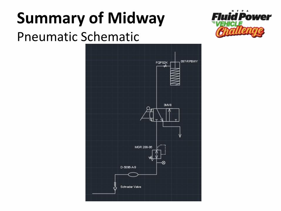
Summary of MidwayPneumatic Schematic

Summary of MidwayComponent Selection – Pneumatics
Air Cylinder Valves
Shrader Valve Air reservoir

Summary of MidwayComponent Selection – Pneumatics
Regulator Flow Control
Cylinder mounting Rod Mounting

Pnuematic Changes
• Actuator
– Before: 7/8 in bore size and 3/8 in diameter
rod @ 30 psi
– After: Power factor of 09 & 7 inch stroke @ 20
psi
• Reservoir
– Before: Was not measured.
– After: 9 inch and 1.5 inch diameter

Electronic Circuit Schematic

Electronic Selection
2-way switch
Battery
3-way switchON-OFF-ON
Spade connectors
18 AWG wire

AnalysesSub - Assembly Component Hand Calculations
CAE (Computer Aided Engineering)
Completed Analysis
Fluid power schematic Fluid power Schematic Hopsan ✓
Hydraulic Components
Motor Sizing calculations ✓
Pump Sizing calculations ✓
Pneumatic ComponentsAir Cylinder & Reservoir
Sizing Calculations ✓
Vehicle
Vehicle with components
CFD X
Gear train Gear Ratios ✓
Frame FEA X
Mounts FEA ✓
Fluid power schematic & Vehicle
Both Subassemblies SimscapeTM X

Analyses -Mounting Manifold
We were originally going to use ¼” steel plate.
After CAE, found that 1/8” steel plate would still work, while providing weight savings of 26.4 lbs.

Vehicle Construction & Assembly• Polycarbonate shielding and reservoir

Vehicle Construction & Assembly• Hose routing

Vehicle Construction & Assembly• Sheet metal

Vehicle Construction & Assembly• Pneumatics

Vehicle Construction & Assembly• Putting it all together!

Vehicle Construction & Assembly• Putting it all together! (cont.)

Vehicle TestingHydraulics• Regenerative Braking
– Bike free wheel does not allow regenerative
braking by coasting, as was intended.
– Left circuit unchanged because regenerative
braking was achievable by pedaling pump.
• Hose Lengths
– Most of the hoses were too short by a hair.
– 90° Fittings were bought.

Vehicle TestingHydraulics• Direct Drive
– Pressure in motor exceeded pressure relief
valve minimum, redirecting fluid to reservoir
– Tuned pressure relief valve to maximum
(2000 psi) to allow motor to turn

Vehicle TestingHydraulics
Polycarbonate Reservoir Steel Reservoir
• Plastic reservoir • Sealant sprung a leak• Replaced with steel reservoir

Vehicle TestingHydraulics• Back pressure on the motor
– Prevent any back pressure that would spin
the motor backwards as we drained the
accumulator in boost mode.
– Added check valve to prevent this.

Revised Hydraulic Schematic
Boost• Check valve was
allowing fluid to go to the reservoir before going through motor
• Line was capped off because theoretical regenerative braking was unachievable
Possible failed check valve
Removed tubing between this
valve and reservoir,
blocked off lines

Vehicle TestingPneumatics• Goal
– Controlled door opening.
– Door maintains closed over long period of time.
• Tuning
– Reservoir: > 60 psi
– Regulator: 25 psi
– Flow control: nearly closed.
• Results
– Door Opening: 3 seconds.
– Door Closed: > 30 minutes.

Vehicle TestingMechanical• Wheel Problem

Vehicle TestingMechanical• Chain tensioning

Final Vehicle

Lessons Learned
• Start manufacturing early. This is very
important.
• Test complete bike as early as possible to
find possible issues or improvements.
• Plan out everything ahead of time e.g.,
knowing where to pre-charge if you do not
have the equipment for it.

Conclusion
• Very good learning experience.
– From very little hydraulic knowledge to
working bike in ~ 7 months.
• Value of teamwork & goal-setting.
• Gained pneumatic, electrical, hydraulic,
tool, and simulation experience.
• Met goals of both class and competition,
simultaneously.

Acknowledgements
• Phillip Sanders
• Ernie Parker
• Stephanie Scaccianoce
• Josh Scarbrough
• Kent Sowatzke

QUESTIONS?