Embed Size (px)
Citation preview
E-TENDERING
E-TENDERING
Project Report

E-TENDERING
ABSTRACT
Project Report
E-TENDERING
Electronic Tendering is carrying out the traditional tendering process in an electronic form, using the
internet. The tendering process is a key business process that helps businesses find a suitable
contractor. In the building and construction industries, clients invite tenderers to submit an estimate of
prices, detailing the costs associated with completing a building. In this way, the client can base their
decision on the result of the tenders to select the most suitable contractor. Currently in Hong Kong,
many of such tendering processes are still mainly manual and paper based. The tenderers need to
collect the tender's booklet, price it, and bring it back to the client's office before the deadline. In this
paper, we present a design and implementation of an e-tendering system by using Web services for the
automation of such tendering processes.
Project Report

E-TENDERING
Preface
Table of Contents
1. INTRODUCTION
1.1 INTRODUCTION TO PROJECT
1.2 ORGANIZATION PROFILE
1.3 PURPOSE OF THE SYSTEM
1.4 PROBLEMS IN EXISTING SYSTEM
1.5 SOLUTION OF THESE PROBLEMS
2. SYSTEM ANALYSIS
2.1 INTRODUCTION
2.2 ANALYSIS MODEL
2.3 STUDY OF THE SYSTEM
2.4 SYSTEM REQUIREMENT SPECIFICATIONS
2.5 PROPOSED SYSTEM
2.6 INPUT AND OUTPUT
2.7 PROCESS MODULES USED WITH JUSTIFICATION
3. FEASIBILITY REPORT
3.1 TECHNICAL FEASIBILITY
3.2 OPERATIONAL FEASIBILITY
3.3 ECONOMICAL FEASIBILTY
4. SOFTWARE REQUIREMENT SPECIFICATIONS
4.1 FUNCTIONAL REQUIREMENTS
4.2 PERFORMANCE REQUIREMENTS
5. SELECTED SOFTWARE
5.1 INTRODUCTION TO .NET FRAME WORK
5.2 ASP.NET
Project Report

E-TENDERING
5.3 C#.NET
5.4 SQL SERVER
6. SYSTEM DESIGN
6.1 INTRODUCTION
6.2 NORMALIZATION
6.3 E-R DIAGRAM
6.4 DATA FLOW DIAGRAMS
6.5 DATA DICTIONARY
6.6 UML DIAGRAMS
7. OUTPUT SCREENS
8. SYSTEM TESTING AND IMPLEMENTATION
8.1 INTRODUCTION
8.2 STRATEGIC APPROACH OF SOFTWARE TESTING
8.3 UNIT TESTING
8.4 TEST CASES
9. SYSTEM SECURITY
9.1 INTRODUCTION
9.2 SECURITY IN SOFTWARE
10. CONCLUSION
11. FUTURE ENHANCEMENTS
12. BIBLOGRAPHY
Project Report

E-TENDERING
INTRODUCTION
1.1 Purpose of Project
This document contains a description for “E-TENDERING” enhancement. This document will contain the functional requirements of the project and how the developers will enhance the project to achieve all the objectives. The SRS will serve as a guide for the client and the developers. Section 2 is concentrated more on the
1.2 Scope of the project
The price of the product on auction increases with every incremental bid. The price
increases as per the minimum bid increment set by the seller. The seller must sell the item to
the highest bidder at the close of the auction. For example, if a seller has put up product 'A' for
sale with a reserve price of Rs.10 and five buyers bid for it with the highest bid coming in from
buyer 'B' who bids Rs.12, the product is sold to 'B' for Rs.12. This is an auction where the
number of units of a particular product for sale is more than one. This simply means that a
number of identical products have been put up for sale by the seller. In an auction like this, there
will obviously be more than one winner. Buyers can also bid for more that one unit of that
product. At the end of the auction all the bidders pay the same price - the lowest winning bid
amount (subject to the reserve price being met) for the product. This is a perfect auction type for
those who wish to sell many units of the same product. Here is how it works: The Seller starts
by listing a minimum price or starting bid for a product and the quantity or number of units for
sale. Bidders specify both a bid price and the quantity they wish to buy. All winning bidders pay
the same price per item - the lowest successful bid. If there are more buyers than items, the
earliest successful bids get the goods. Higher bidders are more likely to get the quantity they
asked for. Bidders can refuse partial quantity. For example, if you place a bid for 10 items and
only 8 are available after the auction, you are not obliged or bound to buy any of them. Example
Case: A seller places 10 pens on auction at Re.1 each. 10 people bid Re. 1 for one pen each. In
this case, all 10 bidders will win a pen for Rs. 1. However if, let's say, five people bid Rs. 1.25
for a pen each and 10 others bid Re. 1. The minimum bid for the pen will be raised to Rs. 1.25
because demand exceeds supply. Because the Rs. 1.25 bidders bid higher than the Re. 1
bidders, they will be guaranteed a pen. The other 5 pens will go to the earliest Re. 1 bidders.
The final price for each pen will be Re. 1 (even though some participants placed a higher bid of
Project Report

E-TENDERING
Rs. 1.25) since all winning bidders pay the same price - which is the lowest successful bid. In
this format at the time of allocation of the quantities the preference is given to the buyer who
puts in the highest bid and he/she will get the quantity he bid for and this flows progressively
down the bidding value stream.
PROJECT OVERVIEW
The general description gives an "executive overview" and is very client-oriented. It expounds on the functional and data requirements of the application. It also lists the limitations, assumptions and dependencies of the application. Section 3.0, the specific requirements section, includes the developers’ technical view of the client's expectation of the application. It also touches on the performance and quality requirements of the application and provides a solid definition of the interface
Project Report
E-TENDERING
SYSTEM ANALYSIS
Project Report

E-TENDERING
2.1 INTRODUCTION
After analyzing the requirements of the task to be performed, the next step is
to analyze the problem and understand its context. The first activity in the phase is
studying the existing system and other is to understand the requirements and
domain of the new system. Both the activities are equally important, but the first
activity serves as a basis of giving the functional specifications and then successful
design of the proposed system. Understanding the properties and requirements of a
new system is more difficult and requires creative thinking and understanding of
existing running system is also difficult, improper understanding of present system
can lead diversion from solution.
2.2 ANALYSIS MODEL
SDLC METHDOLOGIES
This document play a vital role in the development of life cycle (SDLC) as it describes the complete requirement of the system. It means for use by developers and will be the basic during testing phase. Any changes made to the requirements in the future will have to go through formal change approval process.
SPIRAL MODEL was defined by Barry Boehm in his 1988 article, “A spiral Model of Software Development and Enhancement. This model was not the first model to discuss iterative development, but it was the first model to explain why the iteration models.
As originally envisioned, the iterations were typically 6 months to 2 years long. Each phase starts with a design goal and ends with a client reviewing the progress thus far. Analysis and engineering efforts are applied at each phase of the project, with an eye toward the end goal of the project.
The steps for Spiral Model can be generalized as follows:
The new system requirements are defined in as much details as possible. This usually involves interviewing a number of users representing all the external or internal users and other aspects of the existing system.
A preliminary design is created for the new system.
Project Report

E-TENDERING
A first prototype of the new system is constructed from the preliminary design. This is usually a scaled-down system, and represents an approximation of the characteristics of the final product.
A second prototype is evolved by a fourfold procedure:
1. Evaluating the first prototype in terms of its strengths, weakness, and risks.
2. Defining the requirements of the second prototype.
3. Planning an designing the second prototype.
4. Constructing and testing the second prototype.
At the customer option, the entire project can be aborted if the risk is deemed too great. Risk factors might involved development cost overruns, operating-cost miscalculation, or any other factor that could, in the customer’s judgment, result in a less-than-satisfactory final product.
The existing prototype is evaluated in the same manner as was the previous prototype, and if necessary, another prototype is developed from it according to the fourfold procedure outlined above.
The preceding steps are iterated until the customer is satisfied that the refined prototype represents the final product desired.
The final system is constructed, based on the refined prototype.
The final system is thoroughly evaluated and tested. Routine maintenance is carried on a continuing basis to prevent large scale failures and to minimize down time.
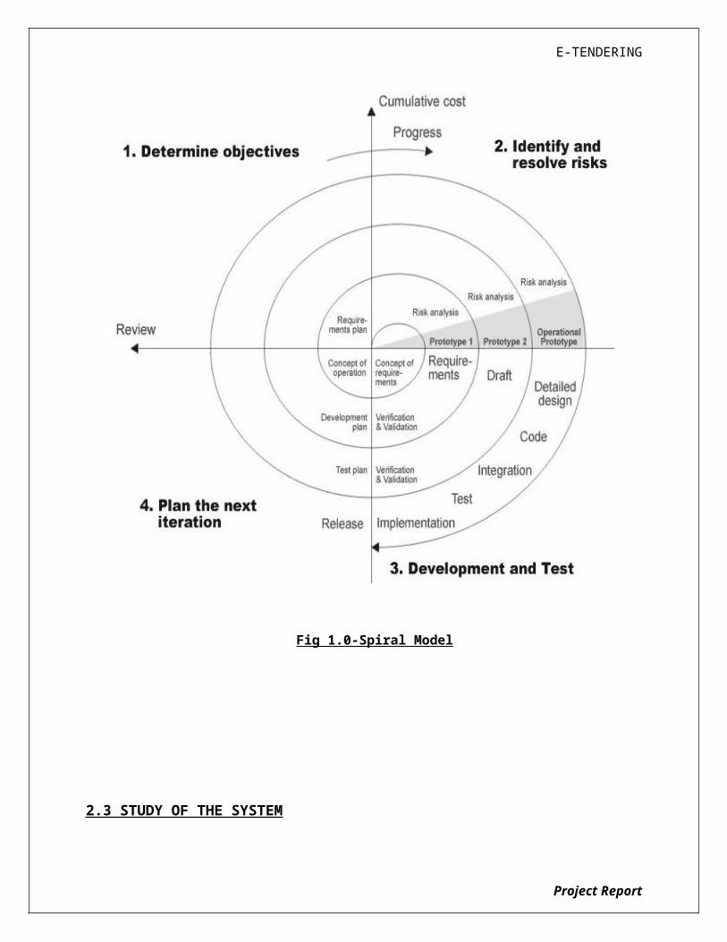
The following diagram shows how a spiral model acts like:
Project Report
E-TENDERING
Fig 1.0-Spiral Model
2.3 STUDY OF THE SYSTEM
Project Report
E-TENDERING
In the flexibility of the uses the interface has been developed a graphics
concept in mind, associated through a browser interface. The GUI’S at the top level
have been categorized as
1. Administrative user interface
2. The operational or generic user interface
The administrative user interface concentrates on the consistent information
that is practically, part of the organizational activities and which needs proper
authentication for the data collection. The interfaces help the administrations with
all the transactional states like Data insertion, Data deletion and Data updating
along with the extensive data search capabilities.
The operational or generic user interface helps the users upon the system in
transactions through the existing data and required services. The operational user
interface also helps the ordinary users in managing their own information helps the
ordinary users in managing their own information in a customized manner as per
the assisted flexibilities
Modules
The project is mainly divided into 4 modules:
1). Administrator
This administrator will maintain all the master information like Items Information, suppliers’
information, Employee information.
2). Employee
He is going to prepare the indent for the required product to the purchase department, and also he
checks indent status.
Project Report
E-TENDERING
3). Purchase Department
Displaying indent information from different departments. Preparation of tenders for the indents,
Invitation to the supplier for the tender
4). Supplier
Supplier is going to bid the amount for tender with in the stipulated time, and will know the final status of the tender once it is closed.
2.4 System Requirement Specifications
Hardware Requirements:
PIV 2.8 GHz Processor and Above
RAM 512MB and Above
HDD 40 GB Hard Disk Space and Above
Software Requirements:
WINDOWS OS (XP / 2000 / 200 Server / 2003 Server)
Visual Studio .Net 2005 Enterprise Edition
Internet Information Server 5.0 (IIS)
Visual Studio .Net Framework (Minimal for Deployment) version 2.0
SQL Server 2005 Enterprise Edition
NEED FOR COMPUTERIZATION
Project Report

E-TENDERING
We all know the importance of computerization. The world is moving
ahead at lightning speed and everyone is running short of time. One always wants
to get the information and perform a task he/she/they desire(s) within a short period
of time and too with amount of efficiency and accuracy. The application areas for
the computerization have been selected on the basis of following factors:
Minimizing the manual records kept at different locations.
There will be more data integrity.
Facilitating desired information display, very quickly, by retrieving information
from users.
Facilitating various statistical information which helps in decision-making?
To reduce manual efforts in activities that involved repetitive work.
Updating and deletion of such a huge amount of data will become easier.
FUNCTIONAL FEATURES OF THE MODEL
As far as the project is developed the functionality is simple, the objective of
the proposal is to strengthen the functioning of Audit Status Monitoring and make
them effective and better. The entire scope has been classified into five streams
knows as Coordinator Level, management Level, Auditor Level, User Level and State
Web Coordinator Level. The proposed software will cover the information needs with
respect to each request of the user group viz. accepting the request, providing
vulnerability document report and the current status of the audit.
Project Report
E-TENDERING
Feasibility Report
Preliminary investigation examine project feasibility, the likelihood the system
will be useful to the organization. The main objective of the feasibility study is to
Project Report

E-TENDERING
test the Technical, Operational and Economical feasibility for adding new modules
and debugging old running system. All system is feasible if they are unlimited
resources and infinite time. There are aspects in the feasibility study portion of the
preliminary investigation:
Technical Feasibility
Operational Feasibility
Economical Feasibility
3.1. TECHNICAL FEASIBILITY
The technical issue usually raised during the feasibility stage of the
investigation includes the following:
Does the necessary technology exist to do what is suggested?
Do the proposed equipments have the technical capacity to hold the data
required to use the new system?
Will the proposed system provide adequate response to inquiries, regardless of
the number or location of users?
Can the system be upgraded if developed?
Are there technical guarantees of accuracy, reliability, ease of access and data
security?
Earlier no system existed to cater to the needs of ‘Secure Infrastructure
Implementation System’. The current system developed is technically feasible. It is
a web based user interface for audit workflow at NIC-CSD. Thus it provides an easy
access to the users. The database’s purpose is to create, establish and maintain a
workflow among various entities in order to facilitate all concerned users in their
various capacities or roles. Permission to the users would be granted based on the
roles specified. Therefore, it provides the technical guarantee of accuracy,
reliability and security. The software and hard requirements for the development of
this project are not many and are already available in-house at NIC or are available
as free as open source. The work for the project is done with the current equipment
and existing software technology. Necessary bandwidth exists for providing a fast
feedback to the users irrespective of the number of users using the system.
3.2. OPERATIONAL FEASIBILITY
Project Report
E-TENDERING
Proposed projects are beneficial only if they can be turned out into
information system. That will meet the organization’s operating requirements.
Operational feasibility aspects of the project are to be taken as an important part of
the project implementation. Some of the important issues raised are to test the
operational feasibility of a project includes the following: -
Is there sufficient support for the management from the users?
Will the system be used and work properly if it is being developed and
implemented?
Will there be any resistance from the user that will undermine the possible
application benefits?
This system is targeted to be in accordance with the above-mentioned issues.
Beforehand, the management issues and user requirements have been taken into
consideration. So there is no question of resistance from the users that can
undermine the possible application benefits.
The well-planned design would ensure the optimal utilization of the computer
resources and would help in the improvement of performance status.
3.3. ECONOMICAL FEASIBILITY
A system can be developed technically and that will be used if installed must
still be a good investment for the organization. In the economical feasibility, the
Project Report
E-TENDERING
development cost in creating the system is evaluated against the ultimate benefit
derived from the new systems. Financial benefits must equal or exceed the costs.
The system is economically feasible. It does not require any addition
hardware or software. Since the interface for this system is developed using the
existing resources and technologies available at NIC, There is nominal expenditure
and economical feasibility for certain.
Project Report
E-TENDERING
SOFTWARE REQUIREMENT SPECIFICATION
The software, Site Explorer is designed for management of web sites from a
remote location.
INTRODUCTION
Purpose: The main purpose for preparing this document is to give a general insight
into the analysis and requirements of the existing system or situation and for
determining the operating characteristics of the system.
Project Report
E-TENDERING
Scope: This Document plays a vital role in the development life cycle (SDLC) and it
describes the complete requirement of the system. It is meant for use by the
developers and will be the basic during testing phase. Any changes made to the
requirements in the future will have to go through formal change approval process.
DEVELOPERS RESPONSIBILITIES OVERVIEW:
The developer is responsible for:
Developing the system, which meets the SRS and solving all the requirements of
the system?
Demonstrating the system and installing the system at client's location after the
acceptance testing is successful.
Submitting the required user manual describing the system interfaces to work on
it and also the documents of the system.
Conducting any user training that might be needed for using the system.
Maintaining the system for a period of one year after installation.
4.1. FUNCTIONAL REQUIREMENTS
OUTPUT DESIGN
Outputs from computer systems are required primarily to communicate the
results of processing to users. They are also used to provides a permanent copy of
the results for later consultation. The various types of outputs in general are:
External Outputs, whose destination is outside the organization.
Internal Outputs whose destination is within organization and they are the
Project Report
E-TENDERING
User’s main interface with the computer.
Operational outputs whose use is purely within the computer department.
Interface outputs, which involve the user in communicating directly.
OUTPUT DEFINITION
The outputs should be defined in terms of the following points:
Type of the output
Content of the output
Format of the output
Location of the output
Frequency of the output
Volume of the output
Sequence of the output
It is not always desirable to print or display data as it is held on a computer. It
should be decided as which form of the output is the most suitable.
For Example
Will decimal points need to be inserted
Should leading zeros be suppressed.
Output Media:
In the next stage it is to be decided that which medium is the most
appropriate for the output. The main considerations when deciding about the output
media are:
The suitability for the device to the particular application.
The need for a hard copy.
The response time required.
The location of the users
The software and hardware available.
Project Report

E-TENDERING
Keeping in view the above description the project is to have outputs mainly coming
under the category of internal outputs. The main outputs desired according to the
requirement specification are:
The outputs were needed to be generated as a hot copy and as well as queries to
be viewed on the screen. Keeping in view these outputs, the format for the output
is taken from the outputs, which are currently being obtained after manual
processing. The standard printer is to be used as output media for hard copies.
INPUT DESIGN
Input design is a part of overall system design. The main objective during the
input design is as given below:
To produce a cost-effective method of input.
To achieve the highest possible level of accuracy.
To ensure that the input is acceptable and understood by the user.
INPUT STAGES:
The main input stages can be listed as below:
Data recording
Data transcription
Data conversion
Data verification
Data control
Data transmission
Data validation
Data correction
INPUT TYPES:
It is necessary to determine the various types of inputs. Inputs can be categorized
as follows:
External inputs, which are prime inputs for the system.
Internal inputs, which are user communications with the system.
Project Report

E-TENDERING
Operational, which are computer department’s communications to the system?
Interactive, which are inputs entered during a dialogue.
INPUT MEDIA:
At this stage choice has to be made about the input media. To conclude
about the input media consideration has to be given to;
Type of input
Flexibility of format
Speed
Accuracy
Verification methods
Rejection rates
Ease of correction
Storage and handling requirements
Security
Easy to use
Portability
Keeping in view the above description of the input types and input media, it
can be said that most of the inputs are of the form of internal and interactive. As
Input data is to be the directly keyed in by the user, the keyboard can be
considered to be the most suitable input device.
ERROR AVOIDANCE
At this stage care is to be taken to ensure that input data remains accurate
form the stage at which it is recorded up to the stage in which the data is accepted
by the system. This can be achieved only by means of careful control each time the
data is handled.
ERROR DETECTION
Even though every effort is make to avoid the occurrence of errors, still a
small proportion of errors is always likely to occur, these types of errors can be
discovered by using validations to check the input data.
Project Report
E-TENDERING
DATA VALIDATION
Procedures are designed to detect errors in data at a lower level of detail.
Data validations have been included in the system in almost every area where there
is a possibility for the user to commit errors. The system will not accept invalid
data. Whenever an invalid data is keyed in, the system immediately prompts the
user and the user has to again key in the data and the system will accept the data
only if the data is correct. Validations have been included where necessary.
The system is designed to be a user friendly one. In other words the system
has been designed to communicate effectively with the user. The system has been
designed with popup menus.
USER INTERFACE DESIGN
It is essential to consult the system users and discuss their needs while
designing the user interface:
USER INTERFACE SYSTEMS CAN BE BROADLY CLASIFIED AS:
1. User initiated interface the user is in charge, controlling the progress of the
user/computer dialogue. In the computer-initiated interface, the computer
selects the next stage in the interaction.
2. Computer initiated interfaces
In the computer initiated interfaces the computer guides the progress of the
user/computer dialogue. Information is displayed and the user response of the
computer takes action or displays further information.
USER_INITIATED INTERGFACES
User initiated interfaces fall into tow approximate classes:
1. Command driven interfaces: In this type of interface the user inputs commands
or queries which are interpreted by the computer.
Project Report

E-TENDERING
2. Forms oriented interface: The user calls up an image of the form to his/her
screen and fills in the form. The forms oriented interface is chosen because it is
the best choice.
COMPUTER-INITIATED INTERFACES
The following computer – initiated interfaces were used:
1. The menu system for the user is presented with a list of alternatives and the
user chooses one; of alternatives.
2. Questions – answer type dialog system where the computer asks question and
takes action based on the basis of the users reply.
Right from the start the system is going to be menu driven, the opening
menu displays the available options. Choosing one option gives another popup
menu with more options. In this way every option leads the users to data entry
form where the user can key in the data.
ERROR MESSAGE DESIGN:
The design of error messages is an important part of the user interface
design. As user is bound to commit some errors or other while designing a system
the system should be designed to be helpful by providing the user with information
regarding the error he/she has committed.
This application must be able to produce output at different modules for different inputs.
4.2. PERFORMANCE REQUIREMENTS
Performance is measured in terms of the output provided by the application.
Requirement specification plays an important part in the analysis of a
system. Only when the requirement specifications are properly given, it is possible
to design a system, which will fit into required environment. It rests largely in the
part of the users of the existing system to give the requirement specifications
because they are the people who finally use the system. This is because the
requirements have to be known during the initial stages so that the system can be
designed according to those requirements. It is very difficult to change the system
Project Report
E-TENDERING
once it has been designed and on the other hand designing a system, which does
not cater to the requirements of the user, is of no use.
The requirement specification for any system can be broadly stated as given
below:
The system should be able to interface with the existing system
The system should be accurate
The system should be better than the existing system
The existing system is completely dependent on the user to perform all the duties.
SELECTED SOFTWARE
Project Report
E-TENDERING
5.1 INTRODUCTION TO .NET FRAMEWORK
The Microsoft .NET Framework is a software technology that is available
with several Microsoft Windows operating systems. It includes a large library of pre-
coded solutions to common programming problems and a virtual machine that
manages the execution of programs written specifically for the framework. The .NET
Framework is a key Microsoft offering and is intended to be used by most new
applications created for the Windows platform.
The pre-coded solutions that form the framework's Base Class Library cover a
large range of programming needs in a number of areas, including user interface,
data access, database connectivity, cryptography, web application development,
numeric algorithms, and network communications. The class library is used by
programmers, who combine it with their own code to produce applications.
Project Report
E-TENDERING
Programs written for the .NET Framework execute in a software environment
that manages the program's runtime requirements. Also part of the .NET
Framework, this runtime environment is known as the Common Language Runtime
(CLR). The CLR provides the appearance of an application virtual machine so that
programmers need not consider the capabilities of the specific CPU that will execute
the program. The CLR also provides other important services such as security,
memory management, and exception handling. The class library and the CLR
together compose the .NET Framework.
Principal design features
Interoperability
Because interaction between new and older applications is commonly
required, the .NET Framework provides means to access functionality that is
implemented in programs that execute outside the .NET environment. Access
to COM components is provided in the System.Runtime.InteropServices and
System.EnterpriseServices namespaces of the framework; access to other
functionality is provided using the P/Invoke feature.
Common Runtime Engine
The Common Language Runtime (CLR) is the virtual machine component of the .NET framework. All .NET programs execute under the supervision of the CLR, guaranteeing certain properties and behaviors in the areas of memory management, security, and exception handling.
Base Class Library
The Base Class Library (BCL), part of the Framework Class Library (FCL), is a library of functionality available to all languages using the .NET Framework. The BCL provides classes which encapsulate a number of common functions,
Project Report
E-TENDERING
including file reading and writing, graphic rendering, database interaction and XML document manipulation.
Simplified Deployment
Installation of computer software must be carefully managed to ensure that it does not interfere with previously installed software, and that it conforms to security requirements. The .NET framework includes design features and tools that help address these requirements.
Security
The design is meant to address some of the vulnerabilities, such as buffer overflows, that have been exploited by malicious software. Additionally, .NET provides a common security model for all applications.
Portability
The design of the .NET Framework allows it to theoretically be platform agnostic, and thus cross-platform compatible. That is, a program written to use the framework should run without change on any type of system for which the framework is implemented. Microsoft's commercial implementations of the framework cover Windows, Windows CE, and the Xbox 360. In addition, Microsoft submits the specifications for the Common Language Infrastructure (which includes the core class libraries, Common Type System, and the Common Intermediate Language), the C# language, and the C++/CLI language to both ECMA and the ISO, making them available as open standards. This makes it possible for third parties to create compatible implementations of the framework and its languages on other platforms.
Architecture
Project Report
E-TENDERING
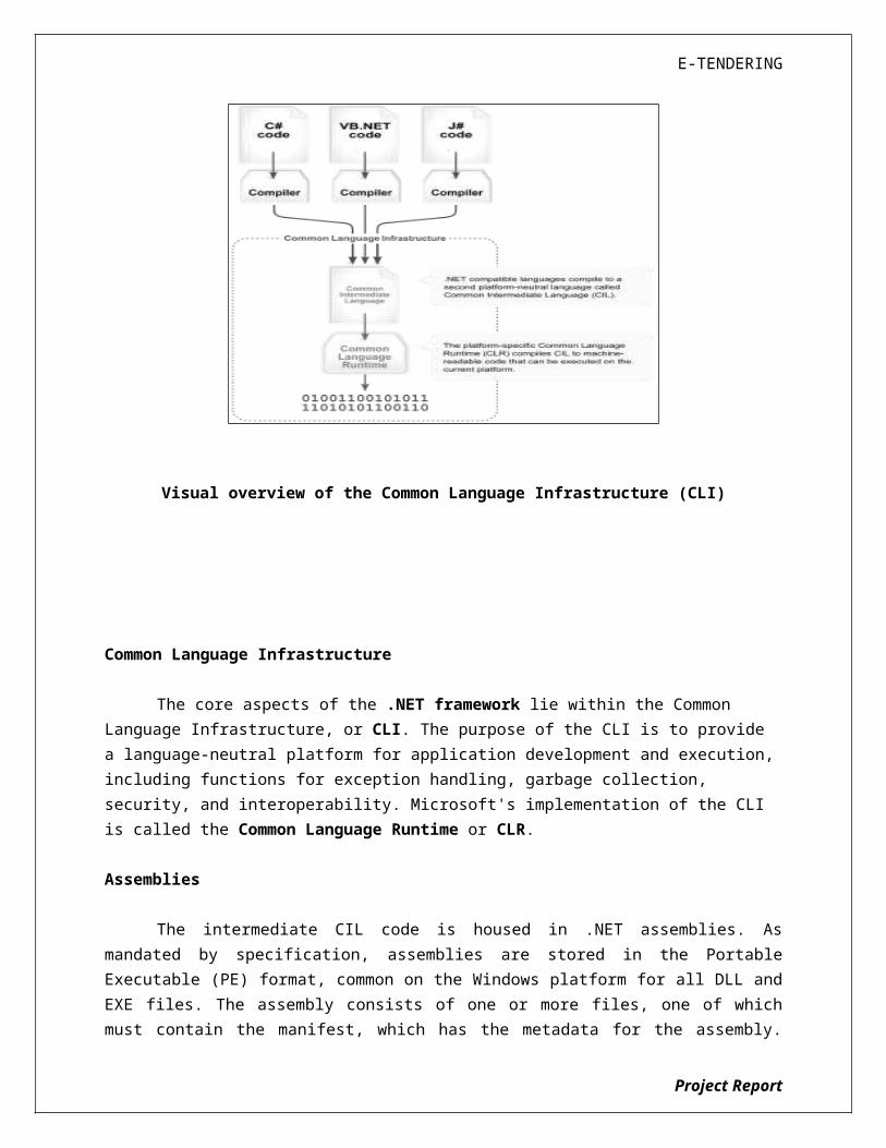
Visual overview of the Common Language Infrastructure (CLI)
Common Language Infrastructure
The core aspects of the .NET framework lie within the Common Language Infrastructure, or CLI. The purpose of the CLI is to provide a language-neutral platform for application development and execution, including functions for exception handling, garbage collection, security, and interoperability. Microsoft's implementation of the CLI is called the Common Language Runtime or CLR.
Assemblies
The intermediate CIL code is housed in .NET assemblies. As mandated by specification, assemblies are stored in the Portable Executable (PE) format, common on the Windows platform for all DLL and EXE files. The assembly consists of one or more files, one of which must contain the manifest, which has the metadata for the assembly. The complete name of an assembly (not to be confused with the filename on disk) contains its simple text name, version number, culture, and public key token. The public key token is a unique hash generated when the assembly is compiled, thus two assemblies with the same public key token are guaranteed to be identical from the point of view of the framework. A private key can also be specified known only to the creator of the assembly and can be used for strong
Project Report
E-TENDERING
naming and to guarantee that the assembly is from the same author when a new version of the assembly is compiled (required to add an assembly to the Global Assembly Cache).
Metadata
All CLI is self-describing through .NET metadata. The CLR checks the metadata to ensure that the correct method is called. Metadata is usually generated by language compilers but developers can create their own metadata through custom attributes. Metadata contains information about the assembly, and is also used to implement the reflective programming capabilities of .NET Framework.
Security
.NET has its own security mechanism with two general features: Code Access Security (CAS), and validation and verification. Code Access Security is based on evidence that is associated with a specific assembly. Typically the evidence is the source of the assembly (whether it is installed on the local machine or has been downloaded from the intranet or Internet). Code Access Security uses evidence to determine the permissions granted to the code. Other code can demand that calling code is granted a specified permission. The demand causes the CLR to perform a call stack walk: every assembly of each method in the call stack is checked for the required permission; if any assembly is not granted the permission a security exception is thrown.
When an assembly is loaded the CLR performs various tests. Two such tests are validation and verification. During validation the CLR checks that the assembly contains valid metadata and CIL, and whether the internal tables are correct. Verification is not so exact. The verification mechanism checks to see if the code does anything that is 'unsafe'. The algorithm used is quite conservative; hence occasionally code that is 'safe' does not pass. Unsafe code will only be executed if the assembly has the 'skip verification' permission, which generally means code that is installed on the local machine.
.NET Framework uses appdomains as a mechanism for isolating code running in a process. Appdomains can be created and code loaded into or unloaded from them independent of other appdomains. This helps increase the fault tolerance of the application, as faults or crashes in one appdomain do not affect rest of the application. Appdomains can also be configured independently with different security privileges. This can help increase the security of the application by isolating potentially unsafe code. The developer, however, has to split the application into sub domains; it is not done by the CLR.
Project Report
E-TENDERING
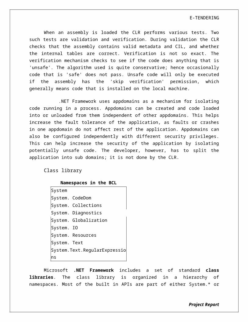
Class library
Namespaces in the BCL
System
System. CodeDom
System. Collections
System. Diagnostics
System. Globalization
System. IO
System. Resources
System. Text
System.Text.RegularExpressions
Microsoft .NET Framework includes a set of standard class libraries. The class library is organized in a hierarchy of namespaces. Most of the built in APIs are part of either System.* or Microsoft.* namespaces. It encapsulates a large number of common functions, such as file reading and writing, graphic rendering, database interaction, and XML document manipulation, among others. The .NET class libraries are available to all .NET languages. The .NET Framework class library is divided into two parts: the Base Class Library and the Framework Class Library.
The Base Class Library (BCL) includes a small subset of the entire class library and is the core set of classes that serve as the basic API of the Common Language Runtime. The classes in mscorlib.dll and some of the classes in System.dll and System.core.dll are considered to be a part of the BCL. The BCL classes are available in both .NET Framework as well as its alternative implementations including .NET Compact Framework, Microsoft Silver light and Mono.
The Framework Class Library (FCL) is a superset of the BCL classes and refers to the entire class library that ships with .NET Framework. It includes an expanded set of libraries, including Win Forms, ADO.NET, ASP.NET, Language Integrated Query, Windows Presentation Foundation, Windows Communication Foundation among others. The FCL is much larger in scope than standard libraries for languages like C++, and comparable in scope to the standard libraries of Java.
Memory management
The .NET Framework CLR frees the developer from the burden of managing memory (allocating and freeing up when done); instead it does the memory management itself. To this end, the memory allocated to instantiations of .NET types (objects) is done contiguously from the managed heap, a pool of memory managed by the CLR. As long as there exists a reference to an object, which might be either a direct reference to an object or via a graph of objects, the object is
Project Report

E-TENDERING
considered to be in use by the CLR. When there is no reference to an object, and it cannot be reached or used, it becomes garbage. However, it still holds on to the memory allocated to it. .NET Framework includes a garbage collector which runs periodically, on a separate thread from the application's thread, that enumerates all the unusable objects and reclaims the memory allocated to them.
The .NET Garbage Collector (GC) is a non-deterministic, compacting, mark-and-sweep garbage collector. The GC runs only when a certain amount of memory has been used or there is enough pressure for memory on the system. Since it is not guaranteed when the conditions to reclaim memory are reached, the GC runs are non-deterministic. Each .NET application has a set of roots, which are pointers to objects on the managed heap (managed objects). These include references to static objects and objects defined as local variables or method parameters currently in scope, as well as objects referred to by CPU registers. When the GC runs, it pauses the application, and for each object referred to in the root, it recursively enumerates all the objects reachable from the root objects and marks them as reachable. It uses .NET metadata and reflection to discover the objects encapsulated by an object, and then recursively walk them. It then enumerates all the objects on the heap (which were initially allocated contiguously) using reflection. All objects not marked as reachable are garbage. This is the mark phase. Since the memory held by garbage is not of any consequence, it is considered free space. However, this leaves chunks of free space between objects which were initially contiguous. The objects are then compacted together, by using memory to copy them over to the free space to make them contiguous again. Any reference to an object invalidated by moving the object is updated to reflect the new location by the GC. The application is resumed after the garbage collection is over.
The GC used by .NET Framework is actually generational. Objects are assigned a generation; newly created objects belong to Generation 0. The objects that survive a garbage collection are tagged as Generation 1, and the Generation 1 objects that survive another collection are Generation 2 objects. The .NET Framework uses up to Generation 2 objects. Higher generation objects are garbage collected less frequently than lower generation objects. This helps increase the efficiency of garbage collection, as older objects tend to have a larger lifetime than newer objects. Thus, by removing older (and thus more likely to survive a collection) objects from the scope of a collection run, fewer objects need to be checked and compacted.
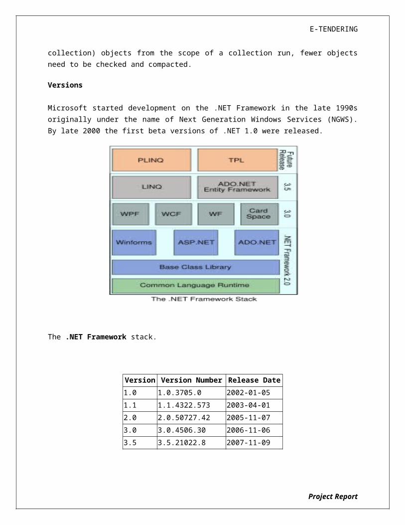
Versions
Microsoft started development on the .NET Framework in the late 1990s originally under the name of Next Generation Windows Services (NGWS). By late 2000 the first beta versions of .NET 1.0 were released.
Project Report

E-TENDERING
The .NET Framework stack.
Version Version Number Release Date
1.0 1.0.3705.0 2002-01-05
1.1 1.1.4322.573 2003-04-01
2.0 2.0.50727.42 2005-11-07
3.0 3.0.4506.30 2006-11-06
3.5 3.5.21022.8 2007-11-09
5.2 ASP.NET
SERVER APPLICATION DEVELOPMENT
Server-side applications in the managed world are implemented through runtime hosts. Unmanaged applications host the common language runtime, which allows your custom managed code to control the behavior of the server. This model provides you with all the features of the common language runtime and class library while gaining the performance and scalability of the host server.
Project Report

E-TENDERING
The following illustration shows a basic network schema with managed code running in different server environments. Servers such as IIS and SQL Server can perform standard operations while your application logic executes through the managed code.
SERVER-SIDE MANAGED CODE
ASP.NET is the hosting environment that enables developers to use the .NET Framework to target Web-based applications. However, ASP.NET is more than just a runtime host; it is a complete architecture for developing Web sites and Internet-distributed objects using managed code. Both Web Forms and XML Web services use IIS and ASP.NET as the publishing mechanism for applications, and both have a collection of supporting classes in the .NET Framework.
XML Web services, an important evolution in Web-based technology, are distributed, server-side application components similar to common Web sites. However, unlike Web-based applications, XML Web services components have no UI and are not targeted for browsers such as Internet Explorer and Netscape Navigator. Instead, XML Web services consist of reusable software components designed to be consumed by other applications, such as traditional client applications, Web-based applications, or even other XML Web services. As a result, XML Web services technology is rapidly moving application development and deployment into the highly distributed environment of the Internet.
If you have used earlier versions of ASP technology, you will immediately notice the improvements that ASP.NET and Web Forms offers. For example, you can develop Web Forms pages in any language that supports the .NET Framework. In addition, your code no longer needs to share the same file with your HTTP text (although it can continue to do so if you prefer). Web Forms pages execute in native machine language because, like any other managed application, they take full advantage of the runtime. In contrast, unmanaged ASP pages are always scripted and interpreted. ASP.NET pages are faster, more functional, and easier to develop than unmanaged ASP pages because they interact with the runtime like any managed application.
The .NET Framework also provides a collection of classes and tools to aid in development and consumption of XML Web services applications. XML Web services are built on standards such as SOAP (a remote procedure-call protocol), XML (an extensible data format), and WSDL ( the Web Services Description Language). The .NET Framework is built on these standards to promote interoperability with non-Microsoft solutions.
For example, the Web Services Description Language tool included with the .NET Framework SDK can query an XML Web service published on the Web, parse its WSDL description, and produce C# or Visual Basic source code that your application can use to become a client of the XML Web service. The source code can create classes derived from classes in the class library that handle all the underlying communication using SOAP and XML parsing. Although you can use the
Project Report
E-TENDERING
class library to consume XML Web services directly, the Web Services Description Language tool and the other tools contained in the SDK facilitate your development efforts with the .NET Framework.
If you develop and publish your own XML Web service, the .NET Framework provides a set of classes that conform to all the underlying communication standards, such as SOAP, WSDL, and XML. Using those classes enables you to focus on the logic of your service, without concerning yourself with the communications infrastructure required by distributed software development.Finally, like Web Forms pages in the managed environment, your XML Web service will run with the speed of native machine language using the scalable communication of IIS.
ACTIVE SERVER PAGES.NET
ASP.NET is a programming framework built on the common language runtime that can be used on a server to build powerful Web applications. ASP.NET offers several important advantages over previous Web development models: Enhanced Performance. ASP.NET is compiled common language runtime
code running on the server. Unlike its interpreted predecessors, ASP.NET can take advantage of early binding, just-in-time compilation, native optimization, and caching services right out of the box. This amounts to dramatically better performance before you ever write a line of code.
World-Class Tool Support. The ASP.NET framework is complemented by a rich toolbox and designer in the Visual Studio integrated development environment. WYSIWYG editing, drag-and-drop server controls, and automatic deployment are just a few of the features this powerful tool provides.
Power and Flexibility. Because ASP.NET is based on the common language runtime, the power and flexibility of that entire platform is available to Web application developers. The .NET Framework class library, Messaging, and Data Access solutions are all seamlessly accessible from the Web. ASP.NET is also language-independent, so you can choose the language that best applies to your application or partition your application across many languages. Further, common language runtime interoperability guarantees that your existing investment in COM-based development is preserved when migrating to ASP.NET.
Simplicity. ASP.NET makes it easy to perform common tasks, from simple form submission and client authentication to deployment and site configuration. For example, the ASP.NET page framework allows you to build user interfaces that cleanly separate application logic from presentation code and to handle events in a simple, Visual Basic - like forms processing model. Additionally, the common language runtime simplifies development, with managed code services such as automatic reference counting and garbage collection.
Manageability. ASP.NET employs a text-based, hierarchical configuration system, which simplifies applying settings to your server environment and Web
Project Report

E-TENDERING
applications. Because configuration information is stored as plain text, new settings may be applied without the aid of local administration tools. This "zero local administration" philosophy extends to deploying ASP.NET Framework applications as well. An ASP.NET Framework application is deployed to a server simply by copying the necessary files to the server. No server restart is required, even to deploy or replace running compiled code.
Scalability and Availability. ASP.NET has been designed with scalability in mind, with features specifically tailored to improve performance in clustered and multiprocessor environments. Further, processes are closely monitored and managed by the ASP.NET runtime, so that if one misbehaves (leaks, deadlocks), a new process can be created in its place, which helps keep your application constantly available to handle requests.
Customizability and Extensibility. ASP.NET delivers a well-factored architecture that allows developers to "plug-in" their code at the appropriate level. In fact, it is possible to extend or replace any subcomponent of the ASP.NET runtime with your own custom-written component. Implementing custom authentication or state services has never been easier.
Security. With built in Windows authentication and per-application configuration, you can be assured that your applications are secure.
LANGUAGE SUPPORT
The Microsoft .NET Platform currently offers built-in support for three languages: C#, Visual Basic, and Java Script.
WHAT IS ASP.NET WEB FORMS?
The ASP.NET Web Forms page framework is a scalable common language runtime programming model that can be used on the server to dynamically generate Web pages.
Intended as a logical evolution of ASP (ASP.NET provides syntax compatibility with existing pages), the ASP.NET Web Forms framework has been specifically designed to address a number of key deficiencies in the previous model. In particular, it provides:
The ability to create and use reusable UI controls that can encapsulate common functionality and thus reduce the amount of code that a page developer has to write.
The ability for developers to cleanly structure their page logic in an orderly fashion (not "spaghetti code").
Project Report
E-TENDERING
The ability for development tools to provide strong WYSIWYG design support for pages (existing ASP code is opaque to tools).
ASP.NET Web Forms pages are text files with an .aspx file name extension. They can be deployed throughout an IIS virtual root directory tree. When a browser client requests .aspx resources, the ASP.NET runtime parses and compiles the target file into a .NET Framework class. This class can then be used to dynamically process incoming requests. (Note that the .aspx file is compiled only the first time it is accessed; the compiled type instance is then reused across multiple requests).
An ASP.NET page can be created simply by taking an existing HTML file and changing its file name extension to .aspx (no modification of code is required). For example, the following sample demonstrates a simple HTML page that collects a user's name and category preference and then performs a form post back to the originating page when a button is clicked:
ASP.NET provides syntax compatibility with existing ASP pages. This includes support for <% %> code render blocks that can be intermixed with HTML content within an .aspx file. These code blocks execute in a top-down manner at page render time.
CODE-BEHIND WEB FORMS
ASP.NET supports two methods of authoring dynamic pages. The first is the method shown in the preceding samples, where the page code is physically declared within the originating .aspx file. An alternative approach--known as the code-behind method--enables the page code to be more cleanly separated from the HTML content into an entirely separate file.
INTRODUCTION TO ASP.NET SERVER CONTROLS
In addition to (or instead of) using <% %> code blocks to program dynamic content, ASP.NET page developers can use ASP.NET server controls to program Web pages. Server controls are declared within an .aspx file using custom tags or intrinsic HTML tags that contain a runat="server" attributes value. Intrinsic HTML tags are handled by one of the controls in the System.Web.UI.HtmlControls namespace. Any tag that doesn't explicitly map to one of the controls is assigned the type of System.Web.UI.HtmlControls.HtmlGenericControl.
Server controls automatically maintain any client-entered values between round trips to the server. This control state is not stored on the server (it is instead
Project Report
E-TENDERING
stored within an <input type="hidden"> form field that is round-tripped between requests). Note also that no client-side script is required.
In addition to supporting standard HTML input controls, ASP.NET enables developers to utilize richer custom controls on their pages. For example, the following sample demonstrates how the <asp:adrotator> control can be used to dynamically display rotating ads on a page.
1. ASP.NET Web Forms provide an easy and powerful way to build dynamic Web UI. 2. ASP.NET Web Forms pages can target any browser client (there are no script
library or cookie requirements). 3. ASP.NET Web Forms pages provide syntax compatibility with existing ASP pages. 4. ASP.NET server controls provide an easy way to encapsulate common
functionality. 5. ASP.NET ships with 45 built-in server controls. Developers can also use controls
built by third parties. 6. ASP.NET server controls can automatically project both uplevel and downlevel
HTML. 7. ASP.NET templates provide an easy way to customize the look and feel of list
server controls. 8. ASP.NET validation controls provide an easy way to do declarative client or
server data validation.
5.3 C#.NET
ADO.NET OVERVIEW
ADO.NET is an evolution of the ADO data access model that directly addresses user requirements for developing scalable applications. It was designed specifically for the web with scalability, statelessness, and XML in mind. ADO.NET uses some ADO objects, such as the Connection and Command objects, and also introduces new objects. Key new ADO.NET objects include the Dataset, Data Reader, and Data Adapter.
The important distinction between this evolved stage of ADO.NET and previous data architectures is that there exists an object -- the DataSet -- that is separate and distinct from any data stores. Because of that, the DataSet functions as a standalone entity. You can think of the DataSet as an always disconnected recordset that knows nothing about the source or destination of the data it contains. Inside a DataSet, much like in a database, there are tables, columns, relationships, constraints, views, and so forth.
Project Report

E-TENDERING
A DataAdapter is the object that connects to the database to fill the DataSet. Then, it connects back to the database to update the data there, based on operations performed while the DataSet held the data. In the past, data processing has been primarily connection-based. Now, in an effort to make multi-tiered apps more efficient, data processing is turning to a message-based approach that revolves around chunks of information. At the center of this approach is the DataAdapter, which provides a bridge to retrieve and save data between a DataSet and its source data store. It accomplishes this by means of requests to the appropriate SQL commands made against the data store.
The XML-based DataSet object provides a consistent programming model that works with all models of data storage: flat, relational, and hierarchical. It does this by having no 'knowledge' of the source of its data, and by representing the data that it holds as collections and data types. No matter what the source of the data within the DataSet is, it is manipulated through the same set of standard APIs exposed through the DataSet and its subordinate objects.
While the DataSet has no knowledge of the source of its data, the managed
provider has detailed and specific information. The role of the managed provider is to connect, fill, and persist the DataSet to and from data stores. The OLE DB and SQL Server .NET Data Providers (System.Data.OleDb and System.Data.SqlClient) that are part of the .Net Framework provide four basic objects: the Command, Connection, DataReader and DataAdapter. In the remaining sections of this document, we'll walk through each part of the DataSet and the OLE DB/SQL Server .NET Data Providers explaining what they are, and how to program against them. The following sections will introduce you to some objects that have evolved, and some that are new. These objects are:
Connections. For connection to and managing transactions against a database.
Commands. For issuing SQL commands against a database. DataReaders. For reading a forward-only stream of data records from a SQL
Server data source. DataSet. For storing, Remoting and programming against flat data, XML data
and relational data. DataAdapters. For pushing data into a DataSet, and reconciling data
against a database.
When dealing with connections to a database, there are two different options: SQL Server .NET Data Provider (System.Data.SqlClient) and OLE DB .NET Data Provider (System.Data.OleDb). In these samples we will use the SQL Server .NET Data Provider. These are written to talk directly to Microsoft SQL Server. The OLE
Project Report
E-TENDERING
DB .NET Data Provider is used to talk to any OLE DB provider (as it uses OLE DB underneath).
Connections:
Connections are used to 'talk to' databases, and are represented by provider-
specific classes such as SqlConnection. Commands travel over connections and
resultsets are returned in the form of streams which can be read by a DataReader
object, or pushed into a DataSet object.
Commands:
Commands contain the information that is submitted to a database, and are
represented by provider-specific classes such as SqlCommand. A command can be
a stored procedure call, an UPDATE statement, or a statement that returns results.
You can also use input and output parameters, and return values as part of your
command syntax. The example below shows how to issue an INSERT statement
against the Northwind database.
DataReaders:
The Data Reader object is somewhat synonymous with a read-only/forward-
only cursor over data. The DataReader API supports flat as well as hierarchical
data. A DataReader object is returned after executing a command against a
database. The format of the returned DataReader object is different from a
recordset. For example, you might use the DataReader to show the results of a
search list in a web page.
DATASETS AND DATAADAPTERS:
DataSets
The Dataset object is similar to the ADO Recordset object, but more
powerful, and with one other important distinction: the DataSet is always
disconnected. The DataSet object represents a cache of data, with database-like
structures such as tables, columns, relationships, and constraints. However, though
a DataSet can and does behave much like a database, it is important to remember
that DataSet objects do not interact directly with databases, or other source data.
Project Report
E-TENDERING
This allows the developer to work with a programming model that is always
consistent, regardless of where the source data resides. Data coming from a
database, an XML file, from code, or user input can all be placed into DataSet
objects. Then, as changes are made to the DataSet they can be tracked and
verified before updating the source data. The GetChanges method of the DataSet
object actually creates a second DatSet that contains only the changes to the data.
This DataSet is then used by a DataAdapter (or other objects) to update the
original data source.
The DataSet has many XML characteristics, including the ability to produce and
consume XML data and XML schemas. XML schemas can be used to describe
schemas interchanged via WebServices. In fact, a DataSet with a schema can
actually be compiled for type safety and statement completion.
DATAADAPTERS (OLEDB/SQL)
The DataAdapter object works as a bridge between the DataSet and the
source data. Using the provider-specific SqlDataAdapter (along with its associated
SqlCommand and SqlConnection) can increase overall performance when
working with a Microsoft SQL Server databases. For other OLE DB-supported
databases, you would use the OleDbDataAdapter object and its associated
OleDbCommand and OleDbConnection objects.
The DataAdapter object uses commands to update the data source after
changes have been made to the DataSet. Using the Fill method of the
DataAdapter calls the SELECT command; using the Update method calls the
INSERT, UPDATE or DELETE command for each changed row. You can explicitly set
these commands in order to control the statements used at runtime to resolve
changes, including the use of stored procedures. For ad-hoc scenarios, a
CommandBuilder object can generate these at run-time based upon a select
statement. However, this run-time generation requires an extra round-trip to the
server in order to gather required metadata, so explicitly providing the INSERT,
UPDATE, and DELETE commands at design time will result in better run-time
performance.
1. ADO.NET is the next evolution of ADO for the .Net Framework.
Project Report

E-TENDERING
2. ADO.NET was created with n-Tier, statelessness and XML in the forefront. Two
new objects, the DataSet and DataAdapter, are provided for these scenarios.
3. ADO.NET can be used to get data from a stream, or to store data in a cache
for updates.
4. There is a lot more information about ADO.NET in the documentation.
5. Remember, you can execute a command directly against the database in
order to do inserts, updates, and deletes. You don't need to first put data into a
DataSet in order to insert, update, or delete it.
Also, you can use a DataSet to bind to the data, move through the data, and navigate data relationships
5.4 SQL SERVER -2005
A database management, or DBMS, gives the user access to their data and
helps them transform the data into information. Such database management
systems include dBase, paradox, IMS, SQL Server and SQL Server. These systems
allow users to create, update and extract information from their database.
A database is a structured collection of data. Data refers to the
characteristics of people, things and events. SQL Server stores each data item in its
own fields. In SQL Server, the fields relating to a particular person, thing or event
are bundled together to form a single complete unit of data, called a record (it can
also be referred to as raw or an occurrence). Each record is made up of a number
of fields. No two fields in a record can have the same field name.
During an SQL Server Database design project, the analysis of your business
needs identifies all the fields or attributes of interest. If your business needs
change over time, you define any additional fields or change the definition of
existing fields.
SQL SERVER TABLES
SQL Server stores records relating to each other in a table. Different tables
are created for the various groups of information. Related tables are grouped
together to form a database.
Project Report

E-TENDERING
PRIMARY KEY
Every table in SQL Server has a field or a combination of fields that uniquely
identifies each record in the table. The Unique identifier is called the Primary Key,
or simply the Key. The primary key provides the means to distinguish one record
from all other in a table. It allows the user and the database system to identify,
locate and refer to one particular record in the database.
RELATIONAL DATABASE
Sometimes all the information of interest to a business operation can be
stored in one table. SQL Server makes it very easy to link the data in multiple
tables. Matching an employee to the department in which they work is one
example. This is what makes SQL Server a relational database management
system, or RDBMS. It stores data in two or more tables and enables you to define
relationships between the table and enables you to define relationships between
the tables.
FOREIGN KEY
When a field is one table matches the primary key of another field is referred
to as a foreign key. A foreign key is a field or a group of fields in one table whose
values match those of the primary key of another table.
REFERENTIAL INTEGRITY
Not only does SQL Server allow you to link multiple tables, it also maintains
consistency between them. Ensuring that the data among related tables is
correctly matched is referred to as maintaining referential integrity.
DATA ABSTRACTION
A major purpose of a database system is to provide users with an abstract
view of the data. This system hides certain details of how the data is stored and
maintained. Data abstraction is divided into three levels.
Project Report
E-TENDERING
Physical level: This is the lowest level of abstraction at which one describes how
the data are actually stored.
Conceptual Level: At this level of database abstraction all the attributed and what
data are actually stored is described and entries and relationship among them.
View level: This is the highest level of abstraction at which one describes only part
of the database.
ADVANTAGES OF RDBMS
Redundancy can be avoided
Inconsistency can be eliminated
Data can be Shared
Standards can be enforced
Security restrictions ca be applied
Integrity can be maintained
Conflicting requirements can be balanced
Data independence can be achieved.
DISADVANTAGES OF DBMS
A significant disadvantage of the DBMS system is cost. In addition to the cost
of purchasing of developing the software, the hardware has to be upgraded to allow
for the extensive programs and the workspace required for their execution and
storage. While centralization reduces duplication, the lack of duplication requires
that the database be adequately backed up so that in case of failure the data can
be recovered.
FEATURES OF SQL SERVER (RDBMS)
SQL SERVER is one of the leading database management systems (DBMS)
because it is the only Database that meets the uncompromising requirements of
today’s most demanding information systems. From complex decision support
systems (DSS) to the most rigorous online transaction processing (OLTP)
application, even application that require simultaneous DSS and OLTP access to the
same critical data, SQL Server leads the industry in both performance and
capability.
Project Report
E-TENDERING
SQL SERVER is a truly portable, distributed, and open DBMS that delivers
unmatched performance, continuous operation and support for every database.
SQL SERVER RDBMS is high performance fault tolerant DBMS which is specially
designed for online transactions processing and for handling large database
application.
SQL SERVER with transactions processing option offers two features which
contribute to very high level of transaction processing throughput, which are
The row level lock manager
ENTERPRISE WIDE DATA SHARING
The unrivaled portability and connectivity of the SQL SERVER DBMS enables
all the systems in the organization to be linked into a singular, integrated
computing resource.
PORTABILITY
SQL SERVER is fully portable to more than 80 distinct hardware and operating
systems platforms, including UNIX, MSDOS, OS/2, Macintosh and dozens of
proprietary platforms. This portability gives complete freedom to choose the
database server platform that meets the system requirements.
OPEN SYSTEMS
SQL SERVER offers a leading implementation of industry –standard SQL. SQL
Server’s open architecture integrates SQL SERVER and non –SQL SERVER DBMS
with industry’s most comprehensive collection of tools, application, and third party
software products SQL Server’s Open architecture provides transparent access to
data from other relational database and even non-relational database.
DISTRIBUTED DATA SHARING
SQL Server’s networking and distributed database capabilities to access data
stored on remote server with the same ease as if the information was stored on a
single local computer. A single SQL statement can access data at multiple sites.
Project Report

E-TENDERING
You can store data where system requirements such as performance, security or
availability dictate.
UNMATCHED PERFORMANCE
The most advanced architecture in the industry allows the SQL SERVER DBMS
to deliver unmatched performance.
SOPHISTICATED CONCURRENCY CONTROL
Real World applications demand access to critical data. With most database
Systems application becomes “contention bound” – which performance is limited
not by the CPU power or by disk I/O, but user waiting on one another for data
access. SQL Server employs full, unrestricted row-level locking and contention free
queries to minimize and in many cases entirely eliminates contention wait times.
NO I/O BOTTLENECKS
SQL Server’s fast commit groups commit and deferred write technologies
dramatically reduce disk I/O bottlenecks. While some database write whole data
block to disk at commit time, SQL Server commits transactions with at most
sequential log file on disk at commit time, On high throughput systems, one
sequential writes typically group commit multiple transactions. Data read by the
transaction remains as shared memory so that other transactions may access that
data without reading it again from disk. Since fast commits write all data necessary
to the recovery to the log file, modified blocks are written back to the database
independently of the transaction commit, when written from memory to disk.
Project Report
E-TENDERING
SYSTEM DESIGN
Project Report
E-TENDERING
6.1. INTRODUCTION
Software design sits at the technical kernel of the software engineering
process and is applied regardless of the development paradigm and area of
application. Design is the first step in the development phase for any engineered
product or system. The designer’s goal is to produce a model or representation of
an entity that will later be built. Beginning, once system requirement have been
specified and analyzed, system design is the first of the three technical activities -
design, code and test that is required to build and verify software.
The importance can be stated with a single word “Quality”. Design is the
place where quality is fostered in software development. Design provides us with
representations of software that can assess for quality. Design is the only way that
we can accurately translate a customer’s view into a finished software product or
system. Software design serves as a foundation for all the software engineering
steps that follow. Without a strong design we risk building an unstable system – one
that will be difficult to test, one whose quality cannot be assessed until the last
stage.
During design, progressive refinement of data structure, program structure,
and procedural details are developed reviewed and documented. System design
can be viewed from either technical or project management perspective. From the
technical point of view, design is comprised of four activities – architectural design,
data structure design, interface design and procedural design.
Project Report
E-TENDERING
6.2 NORMALIZATION
It is a process of converting a relation to a standard form. The process is
used to handle the problems that can arise due to data redundancy i.e. repetition of
data in the database, maintain data integrity as well as handling problems that can
arise due to insertion, updating, deletion anomalies.
Decomposing is the process of splitting relations into multiple relations to
eliminate anomalies and maintain anomalies and maintain data integrity. To do this
we use normal forms or rules for structuring relation.
Insertion anomaly: Inability to add data to the database due to absence of other data.
Deletion anomaly: Unintended loss of data due to deletion of other data.
Update anomaly: Data inconsistency resulting from data redundancy and partial update
Normal Forms: These are the rules for structuring relations that eliminate anomalies.
FIRST NORMAL FORM:
A relation is said to be in first normal form if the values in the relation are
atomic for every attribute in the relation. By this we mean simply that no attribute
value can be a set of values or, as it is sometimes expressed, a repeating group.
SECOND NORMAL FORM:
A relation is said to be in second Normal form is it is in first normal form and
it should satisfy any one of the following rules.
1) Primary key is a not a composite primary key
Project Report

E-TENDERING
2) No non key attributes are present
3) Every non key attribute is fully functionally dependent on full set of primary
key.
THIRD NORMAL FORM:
A relation is said to be in third normal form if their exits no transitive
dependencies.
Transitive Dependency: If two non key attributes depend on each other as well
as on the primary key then they are said to be transitively dependent.
The above normalization principles were applied to decompose the data in
multiple tables thereby making the data to be maintained in a consistent state.
6.3 E-R Diagrams
The relation upon the system is structure through a conceptual
ER-Diagram, which not only specifics the existential entities but also the
standard relations through which the system exists and the cardinalities that are
necessary for the system state to continue.
The entity Relationship Diagram (ERD) depicts the relationship between the data
objects. The ERD is the notation that is used to conduct the date modeling
activity the attributes of each data object noted is the ERD can be described
resign a data object descriptions.
The set of primary components that are identified by the ERD are
Data object
Relationships
Attributes
Various types of indicators.
The primary purpose of the ERD is to represent data objects and their relationships.
Project Report

E-TENDERING
6.4 DATA FLOW DIAGRAMS
A data flow diagram is graphical tool used to describe and analyze
movement of data through a system. These are the central tool and the basis from
which the other components are developed. The transformation of data from input
to output, through processed, may be described logically and independently of
physical components associated with the system. These are known as the logical
data flow diagrams. The physical data flow diagrams show the actual implements
and movement of data between people, departments and workstations. A full
description of a system actually consists of a set of data flow diagrams. Using two
familiar notations Yourdon, Gane and Sarson notation develops the data flow
diagrams. Each component in a DFD is labeled with a descriptive name. Process is
further identified with a number that will be used for identification purpose. The
development of DFD’S is done in several levels. Each process in lower level
diagrams can be broken down into a more detailed DFD in the next level. The lop-
level diagram is often called context diagram. It consists a single process bit, which
plays vital role in studying the current system. The process in the context level
diagram is exploded into other process at the first level DFD.
The idea behind the explosion of a process into more process is that
understanding at one level of detail is exploded into greater detail at the next level.
This is done until further explosion is necessary and an adequate amount of detail is
described for analyst to understand the process.
Larry Constantine first developed the DFD as a way of expressing system
requirements in a graphical from, this lead to the modular design.
A DFD is also known as a “bubble Chart” has the purpose of clarifying system
requirements and identifying major transformations that will become programs in
Project Report

E-TENDERING
system design. So it is the starting point of the design to the lowest level of detail.
A DFD consists of a series of bubbles joined by data flows in the system.
DFD SYMBOLS:
In the DFD, there are four symbols
1. A square defines a source(originator) or destination of system data
2. An arrow identifies data flow. It is the pipeline through which the information
flows
3. A circle or a bubble represents a process that transforms incoming data flow into
outgoing data flows.
4. An open rectangle is a data store, data at rest or a temporary repository of data
Process that transforms data flow.
Source or Destination of data
Data flow
Data Store
CONSTRUCTING A DFD:
Several rules of thumb are used in drawing DFD’S:
Project Report

E-TENDERING
1. Process should be named and numbered for an easy reference. Each name
should be representative of the process.
2. The direction of flow is from top to bottom and from left to right. Data
traditionally flow from source to the destination although they may flow back to
the source. One way to indicate this is to draw long flow line back to a source.
An alternative way is to repeat the source symbol as a destination. Since it is
used more than once in the DFD it is marked with a short diagonal.
3. When a process is exploded into lower level details, they are numbered.
4. The names of data stores and destinations are written in capital letters. Process
and dataflow names have the first letter of each work capitalized.
A DFD typically shows the minimum contents of data store. Each data store
should contain all the data elements that flow in and out.
Questionnaires should contain all the data elements that flow in and out.
Missing interfaces redundancies and like is then accounted for often through
interviews.
SAILENT FEATURES OF DFD’S
1. The DFD shows flow of data, not of control loops and decision are controlled
considerations do not appear on a DFD.
2. The DFD does not indicate the time factor involved in any process whether the
dataflow take place daily, weekly, monthly or yearly.
3. The sequence of events is not brought out on the DFD.
TYPES OF DATA FLOW DIAGRAMS
1. Current Physical
2. Current Logical
3. New Logical
4. New Physical
CURRENT PHYSICAL:
In Current Physical DFD process label include the name of people or their
positions or the names of computer systems that might provide some of the overall
system-processing label includes an identification of the technology used to process
Project Report

E-TENDERING
the data. Similarly data flows and data stores are often labels with the names of
the actual physical media on which data are stored such as file folders, computer
files, business forms or computer tapes.
CURRENT LOGICAL:
The physical aspects at the system are removed as much as possible so that
the current system is reduced to its essence to the data and the processors that
transforms them regardless of actual physical form.
NEW LOGICAL:
This is exactly like a current logical model if the user were completely happy
with the user were completely happy with the functionality of the current system
but had problems with how it was implemented typically through the new logical
model will differ from current logical model while having additional functions,
absolute function removal and inefficient flows recognized.
NEW PHYSICAL:
The new physical represents only the physical implementation of the new
system.
RULES GOVERNING THE DFD’S
PROCESS
1) No process can have only outputs.
2) No process can have only inputs. If an object has only inputs than it must be a
sink.
3) A process has a verb phrase label.
DATA STORE
1) Data cannot move directly from one data store to another data store, a process
must move data.
Project Report

E-TENDERING
2) Data cannot move directly from an outside source to a data store, a process,
which receives, must move data from the source and place the data into data
store
3) A data store has a noun phrase label.
SOURCE OR SINK
The origin and /or destination of data.
1) Data cannot move direly from a source to sink it must be moved by a process
2) A source and /or sink has a noun phrase land
DATA FLOW
1) A Data Flow has only one direction of flow between symbols. It may flow in both
directions between a process and a data store to show a read before an update.
The later is usually indicated however by two separate arrows since these
happen at different type.
2) A join in DFD means that exactly the same data comes from any of two or more
different processes data store or sink to a common location.
3) A data flow cannot go directly back to the same process it leads. There must be
at least one other process that handles the data flow produce some other data
flow returns the original data into the beginning process.
4) A Data flow to a data store means update (delete or change).
5) A data Flow from a data store means retrieve or use.
A data flow has a noun phrase label more than one data flow noun phrase can
appear on a single arrow as long as all of the flows on the same arrow move
together as one package.
DFD Diagrams:
Project Report
E-TENDERING
Login DFD Diagram:
Project Report

E-TENDERING
6.5 DATA DICTIONARY
After carefully understanding the requirements of the client the
entire data storage requirements are divided into tables. The below tables
are normalized to avoid any anomalies during the course of data entry.
Tables Design:
Project Report
E-TENDERING
Login Activity Diagram:
Admin Activity Diagram:
Project Report
E-TENDERING
Admin Login Sequence Diagram
Project Report
E-TENDERING
Collabaration Diagram:
Admin Login Collabaration Diagram:
Project Report
Admin LoginPage BL:Cls_Login() DAL:SqlHelper() Database
1 : Admin Login
2 : ValidateUser()
3 : ExecuteNonQuery()
4 : ExecuteComand()
5 : Return QueryResult()
6: ResponseForValidateUser()

E-TENDERING
Admin Login Page
BL:Clslogin
dAL:SqlHelper
DataBase
1: Admin Login2: Validate User
3: Execute Non Query
4: Execute Command
5: Return Query Result()
6: Response for validate user
Project Report

E-TENDERING
OUTPUT SCREENS
Project Report

E-TENDERING
Home Page
Project Report
E-TENDERING
Admin Page
Project Report

E-TENDERING
Project Report
E-TENDERING
Project Report
E-TENDERING
Project Report

E-TENDERING
Project Report

E-TENDERING
Project Report

E-TENDERING
Project Report

E-TENDERING
SYSTEM TESTING AND IMPLEMENTATION
Project Report
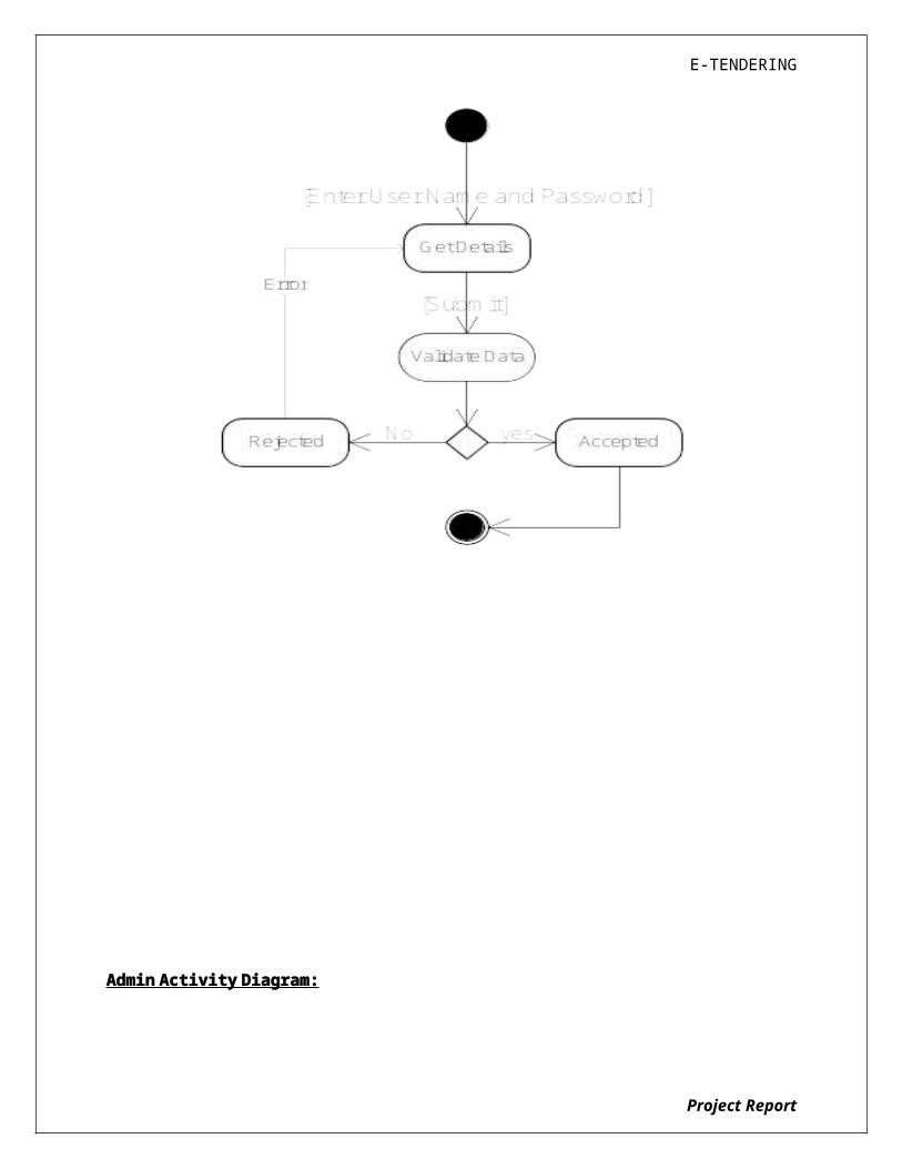
E-TENDERING
8.1 INTRODUCTION
Software testing is a critical element of software quality assurance and
represents the ultimate review of specification, design and coding. In fact, testing is
the one step in the software engineering process that could be viewed as
destructive rather than constructive.
A strategy for software testing integrates software test case design methods
into a well-planned series of steps that result in the successful construction of
software. Testing is the set of activities that can be planned in advance and
conducted systematically. The underlying motivation of program testing is to affirm
software quality with methods that can economically and effectively apply to both
strategic to both large and small-scale systems.
8.2. STRATEGIC APPROACH TO SOFTWARE TESTING
The software engineering process can be viewed as a spiral. Initially system
engineering defines the role of software and leads to software requirement analysis
where the information domain, functions, behavior, performance, constraints and
validation criteria for software are established. Moving inward along the spiral, we
come to design and finally to coding. To develop computer software we spiral in
along streamlines that decrease the level of abstraction on each turn.
A strategy for software testing may also be viewed in the context of the
spiral. Unit testing begins at the vertex of the spiral and concentrates on each unit
of the software as implemented in source code. Testing progress by moving
outward along the spiral to integration testing, where the focus is on the design and
the construction of the software architecture. Talking another turn on outward on
the spiral we encounter validation testing where requirements established as part of
software requirements analysis are validated against the software that has been
constructed. Finally we arrive at system testing, where the software and other
system elements are tested as a whole.
Project Report

E-TENDERING
8.3. UNIT TESTING
Project Report
UNIT TESTING
MODULE TESTING
SUB-SYSTEM TESING
SYSTEM TESTING
ACCEPTANCE TESTING
Component Testing
Integration Testing
User Testing

E-TENDERING
Unit testing focuses verification effort on the smallest unit of software design, the
module. The unit testing we have is white box oriented and some modules the steps
are conducted in parallel.
1. WHITE BOX TESTING
This type of testing ensures that
All independent paths have been exercised at least once
All logical decisions have been exercised on their true and false sides
All loops are executed at their boundaries and within their operational bounds
All internal data structures have been exercised to assure their validity.
To follow the concept of white box testing we have tested each form .we
have created independently to verify that Data flow is correct, All conditions are
exercised to check their validity, All loops are executed on their boundaries.
2. BASIC PATH TESTING
Established technique of flow graph with Cyclomatic complexity was used to derive test cases for all the functions. The main steps in deriving test cases were:
Use the design of the code and draw correspondent flow graph.
Determine the Cyclomatic complexity of resultant flow graph, using formula:
V(G)=E-N+2 or
V(G)=P+1 or
V(G)=Number Of Regions
Where V(G) is Cyclomatic complexity,
E is the number of edges,
N is the number of flow graph nodes,
P is the number of predicate nodes.
Determine the basis of set of linearly independent paths.
3. CONDITIONAL TESTING
Project Report

E-TENDERING
In this part of the testing each of the conditions were tested to both true and false aspects. And all the resulting paths were tested. So that each path that may be generate on particular condition is traced to uncover any possible errors.
4. DATA FLOW TESTING
This type of testing selects the path of the program according to the location of
definition and use of variables. This kind of testing was used only when some local
variable were declared. The definition-use chain method was used in this type of
testing. These were particularly useful in nested statements.
5. LOOP TESTING
In this type of testing all the loops are tested to all the limits possible. The following exercise was adopted for all loops:
All the loops were tested at their limits, just above them and just below them.
All the loops were skipped at least once.
For nested loops test the inner most loop first and then work outwards.
For concatenated loops the values of dependent loops were set with the help of connected loop.
Unstructured loops were resolved into nested loops or concatenated loops and tested as above.
Each unit has been separately tested by the development team itself and all the input have been validated.
8.4 TEST CASES
Paste Your Project Test Cases Here
Project Report

E-TENDERING
SYSTEM SECURITY
9.1 INTRODUCTION
The protection of computer based resources that includes hardware, software, data, procedures and people against unauthorized use or natural
Disaster is known as System Security.
Project Report

E-TENDERING
System Security can be divided into four related issues:
Security Integrity Privacy Confidentiality
SYSTEM SECURITY refers to the technical innovations and procedures applied to the hardware and operation systems to protect against deliberate or accidental damage from a defined threat.
DATA SECURITY is the protection of data from loss, disclosure, modification and destruction.
SYSTEM INTEGRITY refers to the power functioning of hardware and programs, appropriate physical security and safety against external threats such as eavesdropping and wiretapping.
PRIVACY defines the rights of the user or organizations to determine what information they are willing to share with or accept from others and how the organization can be protected against unwelcome, unfair or excessive dissemination of information about it.
CONFIDENTIALITY is a special status given to sensitive information in a database to minimize the possible invasion of privacy. It is an attribute of information that characterizes its need for protection.
9.3 SECURITY SOFTWARE
System security refers to various validations on data in form of checks and controls to avoid the system from failing. It is always important to ensure that only valid data is entered and only valid operations are performed on the system. The system employees two types of checks and controls:
CLIENT SIDE VALIDATION
Various client side validations are used to ensure on the client side that only valid data is entered. Client side validation saves server time and load to handle invalid data. Some checks imposed are:
VBScript in used to ensure those required fields are filled with suitable data only. Maximum lengths of the fields of the forms are appropriately defined.
Project Report

E-TENDERING
Forms cannot be submitted without filling up the mandatory data so that manual mistakes of submitting empty fields that are mandatory can be sorted out at the client side to save the server time and load.
Tab-indexes are set according to the need and taking into account the ease of user while working with the system.
SERVER SIDE VALIDATION
Some checks cannot be applied at client side. Server side checks are necessary to save the system from failing and intimating the user that some invalid operation has been performed or the performed operation is restricted. Some of the server side checks imposed is:
Server side constraint has been imposed to check for the validity of primary key and foreign key. A primary key value cannot be duplicated. Any attempt to duplicate the primary value results into a message intimating the user about those values through the forms using foreign key can be updated only of the existing foreign key values.
User is intimating through appropriate messages about the successful operations or exceptions occurring at server side.
Various Access Control Mechanisms have been built so that one user may not agitate upon another. Access permissions to various types of users are controlled according to the organizational structure. Only permitted users can log on to the system and can have access according to their category. User- name, passwords and permissions are controlled o the server side.
Using server side validation, constraints on several restricted operations are imposed.
Project Report
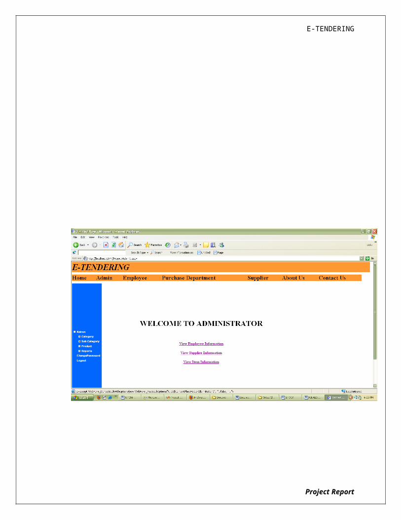
E-TENDERING
CONCLUSION
It has been a great pleasure for me to work on this exciting and challenging project. This project proved good for me as it provided practical knowledge of not only programming in ASP.NET and C#.NET web based application and no some extent Windows Application and SQL Server, but also about all handling procedure related with “E-Tendering”. It also provides knowledge about the latest technology used in developing web enabled application and client server technology that will be great demand in future. This will provide better opportunities and guidance in future in developing projects independently.
BENEFITS:
Project Report

E-TENDERING
The project is identified by the merits of the system offered to the user. The merits of this project are as follows: -
It’s a web-enabled project. This project offers user to enter the data through simple and interactive forms.
This is very helpful for the client to enter the desired information through so much simplicity.
The user is mainly more concerned about the validity of the data, whatever he is entering. There are checks on every stages of any new creation, data entry or updation so that the user cannot enter the invalid data, which can create problems at later date.
Sometimes the user finds in the later stages of using project that he needs to update some of the information that he entered earlier. There are options for him by which he can update the records. Moreover there is restriction for his that he cannot change the primary data field. This keeps the validity of the data to longer extent.
User is provided the option of monitoring the records he entered earlier. He can see the desired records with the variety of options provided by him.
From every part of the project the user is provided with the links through framing so that he can go from one option of the project to other as per the requirement. This is bound to be simple and very friendly as per the user is concerned. That is, we can sat that the project is user friendly which is one of the primary concerns of any good project.
Data storage and retrieval will become faster and easier to maintain because data is stored in a systematic manner and in a single database.
Decision making process would be greatly enhanced because of faster processing of information since data collection from information available on computer takes much less time then manual system.
Allocating of sample results becomes much faster because at a time the user can see the records of last years.
Easier and faster data transfer through latest technology associated with the computer and communication.
Through these features it will increase the efficiency, accuracy and transparency,
LIMITATIONS:
The size of the database increases day-by-day, increasing the load on the database back up and data maintenance activity.
Training for simple computer operations is necessary for the users working on the system.
Project Report

E-TENDERING
Project Report
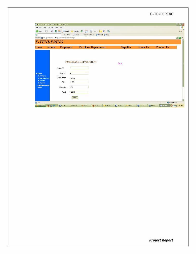
E-TENDERING
BIBLIOGRAPHY
FOR .NET INSTALLATION
www.support.mircosoft.com
FOR DEPLOYMENT AND PACKING ON SERVER
www.developer.com
www.15seconds.com
FOR SQL
www.msdn.microsoft.com
Project Report
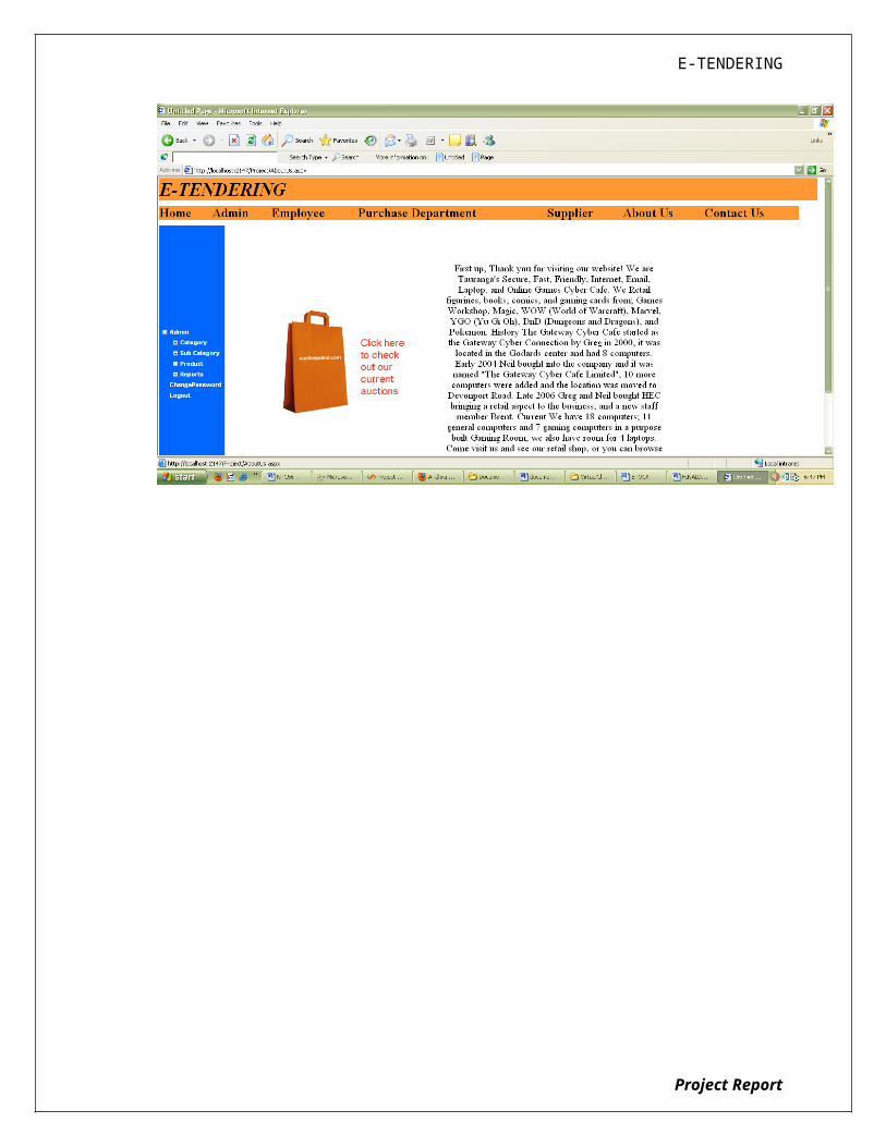
E-TENDERING
FOR ASP.NET
Asp.Net 3.5 Unleashed
www.msdn.microsoft.com/net/quickstart/aspplus/
default.com
www.asp.net
www.fmexpense.com/quickstart/aspplus/default.com
www.asptoday.com
www.aspfree.com
www.4guysfromrolla.com/index.aspx
Software Engineering (Roger’s Pressman)
Project Report