Embed Size (px)
Citation preview
Final Design Report: The Clipper Clapper
Prepared for:
Dr. Gabriela Marquez Shirley Ryan Ability Lab Chicago, Illinois
Date:
December 2, 2017
Submitted by:
Caitlin Draper, Elise Lee, Steven Han Section 15, Team 3
Sponsored by:
Design Thinking and Communication Program Professors John Anderson and Casey Ankeny McCormick School of Engineering and Applied Science Northwestern University Evanston, Illinois 60208
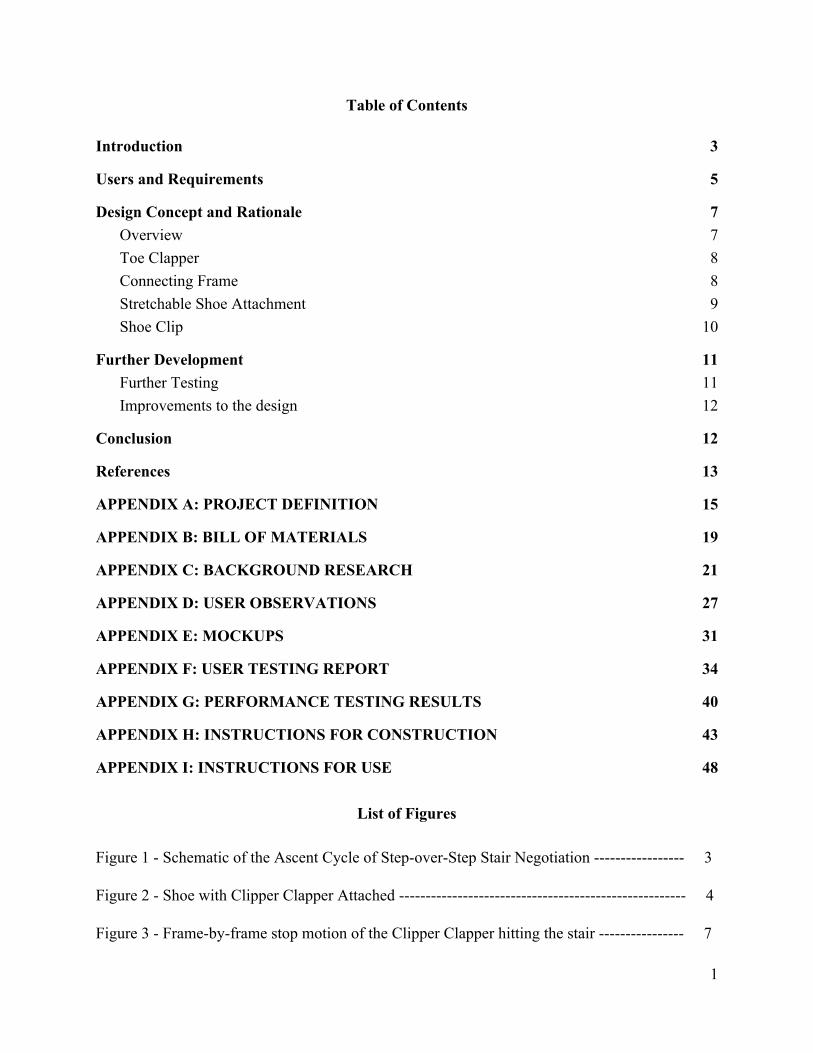
Table of Contents
Introduction 3
Users and Requirements 5
Design Concept and Rationale 7 Overview 7 Toe Clapper 8 Connecting Frame 8 Stretchable Shoe Attachment 9 Shoe Clip 10
Further Development 11 Further Testing 11 Improvements to the design 12
Conclusion 12
References 13
APPENDIX A: PROJECT DEFINITION 15
APPENDIX B: BILL OF MATERIALS 19
APPENDIX C: BACKGROUND RESEARCH 21
APPENDIX D: USER OBSERVATIONS 27
APPENDIX E: MOCKUPS 31
APPENDIX F: USER TESTING REPORT 34
APPENDIX G: PERFORMANCE TESTING RESULTS 40
APPENDIX H: INSTRUCTIONS FOR CONSTRUCTION 43
APPENDIX I: INSTRUCTIONS FOR USE 48
List of Figures
Figure 1 - Schematic of the Ascent Cycle of Step-over-Step Stair Negotiation ----------------- 3 Figure 2 - Shoe with Clipper Clapper Attached ------------------------------------------------------ 4 Figure 3 - Frame-by-frame stop motion of the Clipper Clapper hitting the stair ---------------- 7
1
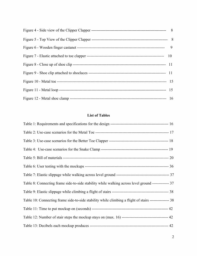
Figure 4 - Side view of the Clipper Clapper ---------------------------------------------------------- 8 Figure 5 - Top View of the Clipper Clapper ----------------------------------------------------------- 8
Figure 6 - Wooden finger castanet -------------------------------------------------------------------- 9
Figure 7 - Elastic attached to toe clapper ------------------------------------------------------------ 10
Figure 8 - Close up of shoe clip ------------------------------------------------------------------------ 11
Figure 9 - Shoe clip attached to shoelaces ------------------------------------------------------------ 11
Figure 10 - Metal toe ------------------------------------------------------------------------------------- 15
Figure 11 - Metal loop ----------------------------------------------------------------------------------- 15
Figure 12 - Metal shoe clamp --------------------------------------------------------------------------- 16
List of Tables
Table 1: Requirements and specifications for the design --------------------------------------------- 16
Table 2: Use-case scenarios for the Metal Toe --------------------------------------------------------- 17
Table 3: Use-case scenarios for the Better Toe Clapper ---------------------------------------------- 18
Table 4: Use-case scenarios for the Snake Clamp ---------------------------------------------------- 19
Table 5: Bill of materials ---------------------------------------------------------------------------------- 20
Table 6: User testing with the mockups ----------------------------------------------------------------- 36
Table 7: Elastic slippage while walking across level ground ----------------------------------------- 37
Table 8: Connecting frame side-to-side stability while walking across level ground ------------- 37
Table 9: Elastic slippage while climbing a flight of stairs -------------------------------------------- 38
Table 10: Connecting frame side-to-side stability while climbing a flight of stairs --------------- 38
Table 11: Time to put mockup on (seconds) ----------------------------------------------------------- 42
Table 12: Number of stair steps the mockup stays on (max. 16) ------------------------------------ 42
Table 13: Decibels each mockup produces ------------------------------------------------------------- 42
2

Table 14: Materials used in constructing the Clipper Clapper --------------------------------------- 44
3
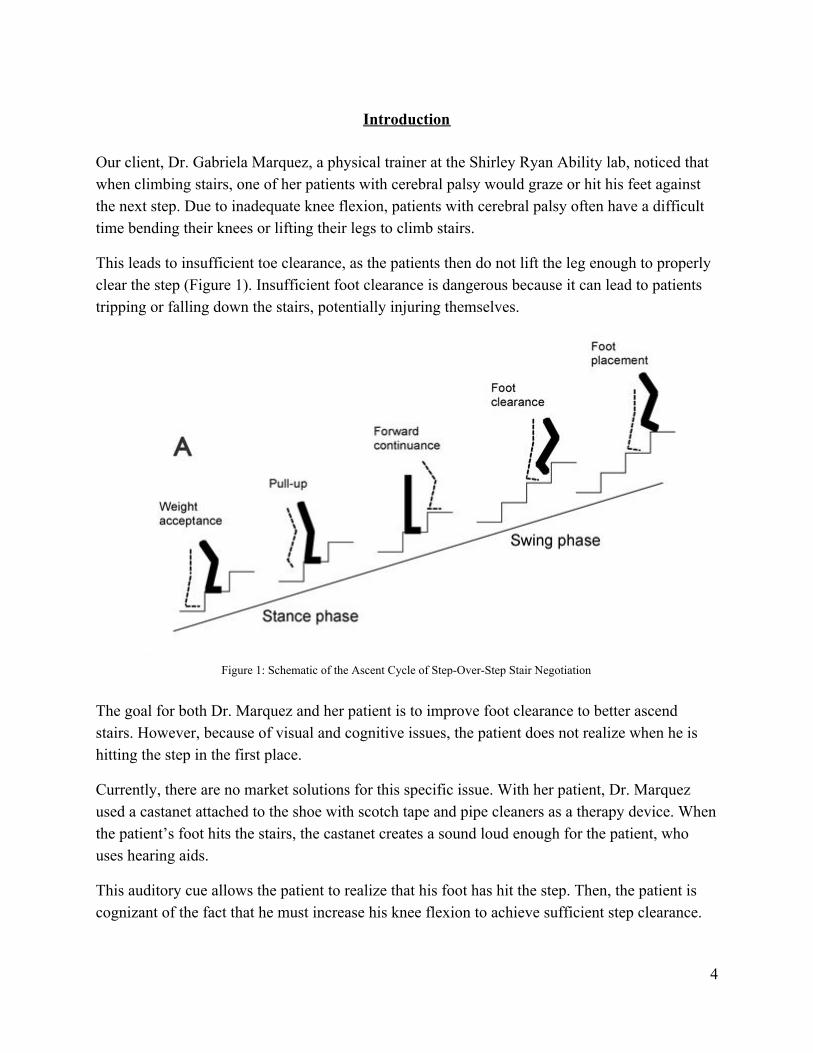
Introduction Our client, Dr. Gabriela Marquez, a physical trainer at the Shirley Ryan Ability lab, noticed that when climbing stairs, one of her patients with cerebral palsy would graze or hit his feet against the next step. Due to inadequate knee flexion, patients with cerebral palsy often have a difficult time bending their knees or lifting their legs to climb stairs.
This leads to insufficient toe clearance, as the patients then do not lift the leg enough to properly clear the step (Figure 1). Insufficient foot clearance is dangerous because it can lead to patients tripping or falling down the stairs, potentially injuring themselves.
Figure 1: Schematic of the Ascent Cycle of Step-Over-Step Stair Negotiation
The goal for both Dr. Marquez and her patient is to improve foot clearance to better ascend stairs. However, because of visual and cognitive issues, the patient does not realize when he is hitting the step in the first place.
Currently, there are no market solutions for this specific issue. With her patient, Dr. Marquez used a castanet attached to the shoe with scotch tape and pipe cleaners as a therapy device. When the patient’s foot hits the stairs, the castanet creates a sound loud enough for the patient, who uses hearing aids.
This auditory cue allows the patient to realize that his foot has hit the step. Then, the patient is cognizant of the fact that he must increase his knee flexion to achieve sufficient step clearance.
4
However, there were two main problems in this solution. First, the scotch tape provided insufficient support for the castanet to stay on the shoe. The piece of tape was not strong enough to keep the castanet in place, so the castanet would fall off as the patient walked. Second, the pipe cleaner was inconvenient as it was not very quick or easy to attach a pipe cleaner to the shoe every time the device was used.
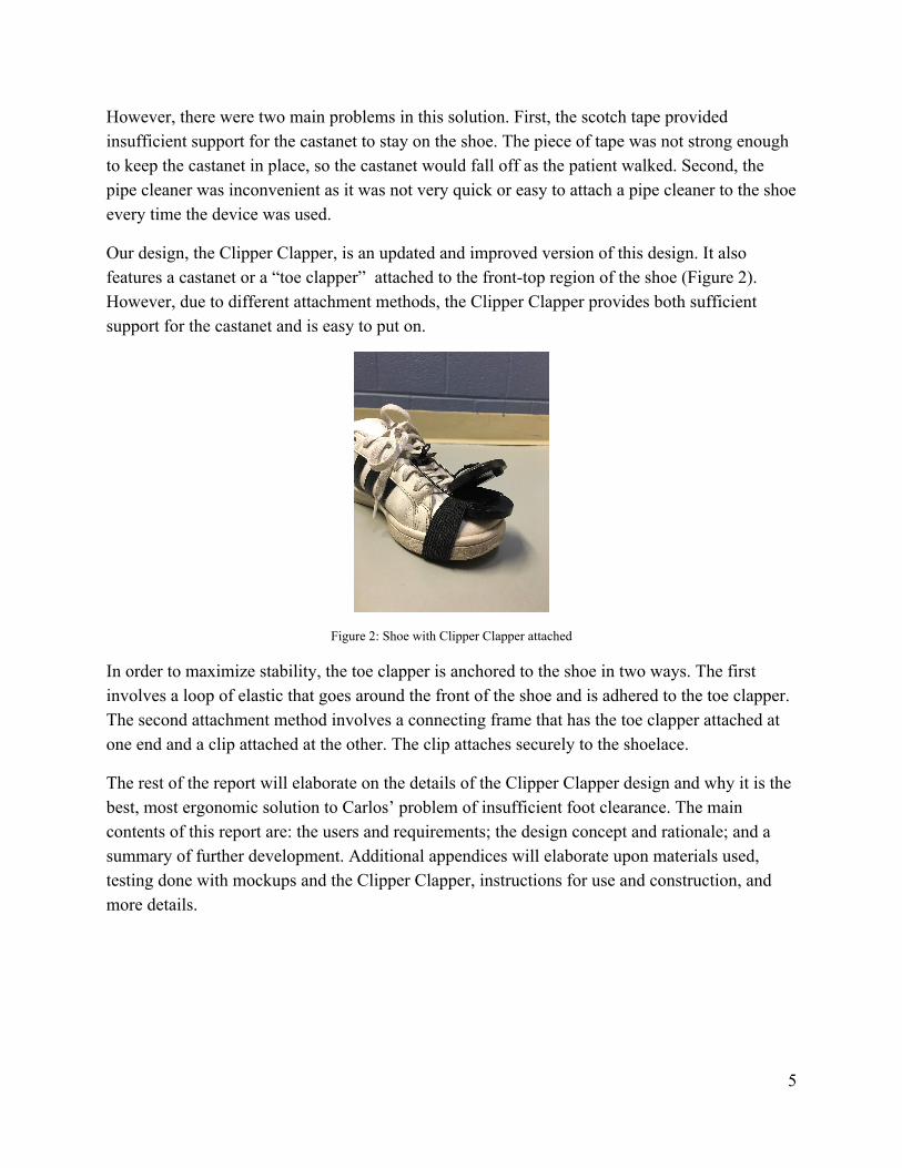
Our design, the Clipper Clapper, is an updated and improved version of this design. It also features a castanet or a “toe clapper” attached to the front-top region of the shoe (Figure 2). However, due to different attachment methods, the Clipper Clapper provides both sufficient support for the castanet and is easy to put on.
Figure 2: Shoe with Clipper Clapper attached
In order to maximize stability, the toe clapper is anchored to the shoe in two ways. The first involves a loop of elastic that goes around the front of the shoe and is adhered to the toe clapper. The second attachment method involves a connecting frame that has the toe clapper attached at one end and a clip attached at the other. The clip attaches securely to the shoelace.
The rest of the report will elaborate on the details of the Clipper Clapper design and why it is the best, most ergonomic solution to Carlos’ problem of insufficient foot clearance. The main contents of this report are: the users and requirements; the design concept and rationale; and a summary of further development. Additional appendices will elaborate upon materials used, testing done with mockups and the Clipper Clapper, instructions for use and construction, and more details.
5
Users and Requirements Main Users of the Design
Teenager with cerebral palsy: The main user is an 18-year-old with cerebral palsy, which is described as a condition with problems involving the nervous system (refer to Appendix B). When ascending the stairs, the user has difficulty raising his legs high enough to clear steps because of weak signaling within his nervous system. The user would like to be able to climb stairs without hitting or grazing his foot against the steps, which can lead to tripping or falling.
Physical therapist at Shirley-Ryan Ability Lab: Dr. Marquez is a physical trainer who works closely with the user to help him climb stairs and use the device correctly.
User’s mother: She guides the user through everyday activities and will help him put on and use the device.
Design Requirements
Audible cue: The purpose of the device is to create an audible cue so it must be loud enough for the user to hear.
Easy to use: The user has decreased motor control and has below-average control over his muscles. His mother must also be able to put the device on with little difficulty and understand how it works.
Does not interfere with user walking: As the user already has difficulty climbing the stairs, the device should not get in the way of or alter the user’s gait.
Safe: Stairs are a potential safety hazard so the design should not pose a risk to the user falling or tripping.
Lightweight: The user’s problem is raising his leg high enough to clear each step, so the design should add minimal weight to the his foot. Additionally, the user has below-average leg strength so the product should not strain his muscles.
Durable: The device will be placed on the user’s foot and strike surfaces repeatedly. It must be able to sustain these stresses throughout the days, weeks and months that the user uses the device for therapy.
6
Stable: The device needs to stay in one place on the user’s shoe to maximize effectiveness. If the device does not create a noise when struck or creates noise in the wrong circumstances, it will not help the user solve his problems.
No lateral movement of device: The device can’t move side to side on the shoe or else there is a chance that incorrect positioning of the device means a noise will not be made when the user hits the stair, thus defeating the purpose of the design.
7
Design Concept and Rationale Overview
The Clipper Clapper is a therapeutic device with the goal of improving user foot clearance when ascending stairs. The Clipper Clapper is designed specifically for one user, an eighteen-year old with cerebral palsy, who hits or grazes several steps of the stairs because his foot does not achieve sufficient clearance. It is designed to be put on only one foot so that the user has stability with the other foot; since the user already has difficulty with motor movement, the design’s goal is to not interfere with that which is why it is not a two-footed design.
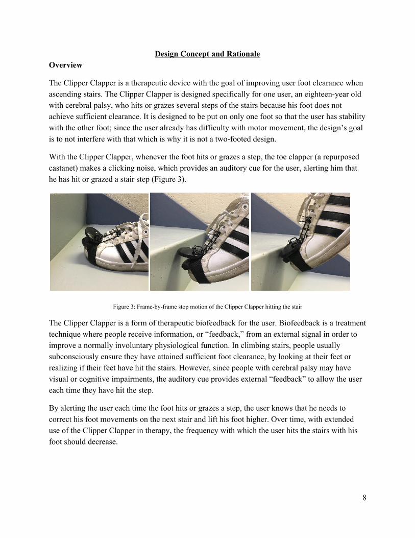
With the Clipper Clapper, whenever the foot hits or grazes a step, the toe clapper (a repurposed castanet) makes a clicking noise, which provides an auditory cue for the user, alerting him that he has hit or grazed a stair step (Figure 3).
Figure 3: Frame-by-frame stop motion of the Clipper Clapper hitting the stair
The Clipper Clapper is a form of therapeutic biofeedback for the user. Biofeedback is a treatment technique where people receive information, or “feedback,” from an external signal in order to improve a normally involuntary physiological function. In climbing stairs, people usually subconsciously ensure they have attained sufficient foot clearance, by looking at their feet or realizing if their feet have hit the stairs. However, since people with cerebral palsy may have visual or cognitive impairments, the auditory cue provides external “feedback” to allow the user each time they have hit the step.
By alerting the user each time the foot hits or grazes a step, the user knows that he needs to correct his foot movements on the next stair and lift his foot higher. Over time, with extended use of the Clipper Clapper in therapy, the frequency with which the user hits the stairs with his foot should decrease.
8
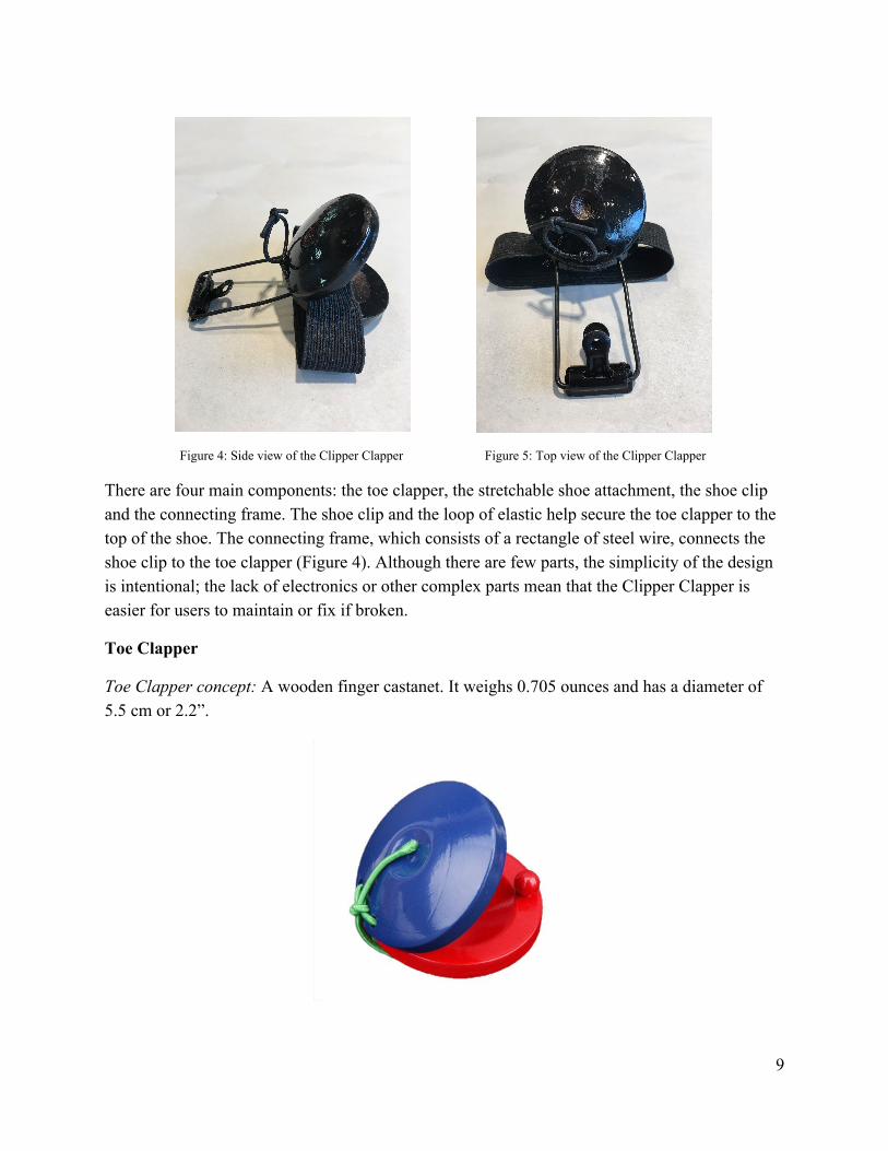
Figure 4: Side view of the Clipper Clapper Figure 5: Top view of the Clipper Clapper
There are four main components: the toe clapper, the stretchable shoe attachment, the shoe clip and the connecting frame. The shoe clip and the loop of elastic help secure the toe clapper to the top of the shoe. The connecting frame, which consists of a rectangle of steel wire, connects the shoe clip to the toe clapper (Figure 4). Although there are few parts, the simplicity of the design is intentional; the lack of electronics or other complex parts mean that the Clipper Clapper is easier for users to maintain or fix if broken.
Toe Clapper
Toe Clapper concept: A wooden finger castanet. It weighs 0.705 ounces and has a diameter of 5.5 cm or 2.2”.
9
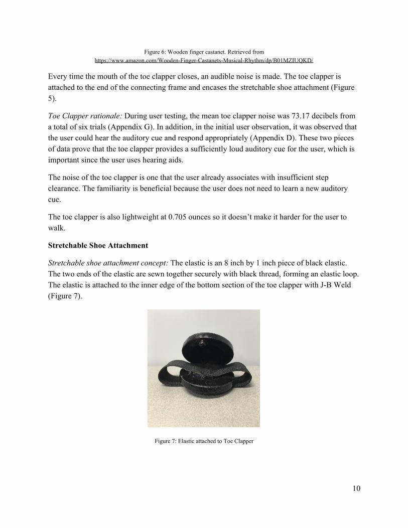
Figure 6: Wooden finger castanet. Retrieved from https://www.amazon.com/Wooden-Finger-Castanets-Musical-Rhythm/dp/B01MZIUQKD/
Every time the mouth of the toe clapper closes, an audible noise is made. The toe clapper is attached to the end of the connecting frame and encases the stretchable shoe attachment (Figure 5).
Toe Clapper rationale: During user testing, the mean toe clapper noise was 73.17 decibels from a total of six trials (Appendix G). In addition, in the initial user observation, it was observed that the user could hear the auditory cue and respond appropriately (Appendix D). These two pieces of data prove that the toe clapper provides a sufficiently loud auditory cue for the user, which is important since the user uses hearing aids.
The noise of the toe clapper is one that the user already associates with insufficient step clearance. The familiarity is beneficial because the user does not need to learn a new auditory cue.
The toe clapper is also lightweight at 0.705 ounces so it doesn’t make it harder for the user to walk.
Stretchable Shoe Attachment
Stretchable shoe attachment concept: The elastic is an 8 inch by 1 inch piece of black elastic. The two ends of the elastic are sewn together securely with black thread, forming an elastic loop. The elastic is attached to the inner edge of the bottom section of the toe clapper with J-B Weld (Figure 7).
Figure 7: Elastic attached to Toe Clapper
10
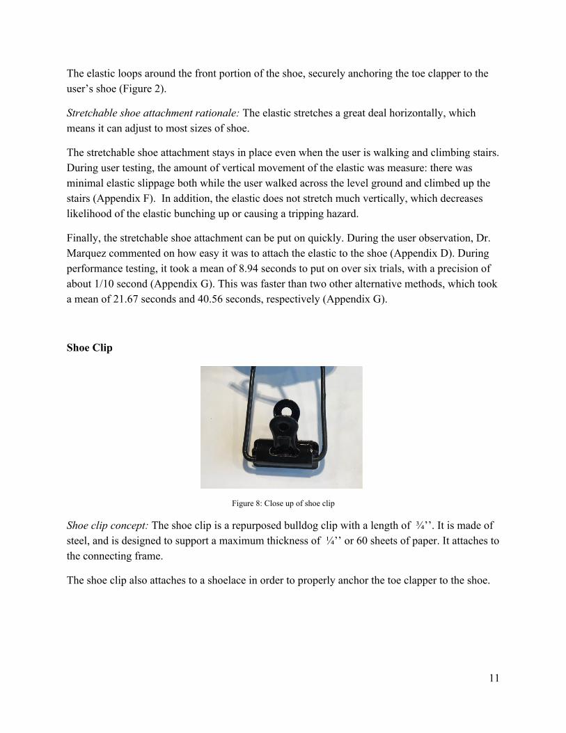
The elastic loops around the front portion of the shoe, securely anchoring the toe clapper to the user’s shoe (Figure 2).
Stretchable shoe attachment rationale: The elastic stretches a great deal horizontally, which means it can adjust to most sizes of shoe.
The stretchable shoe attachment stays in place even when the user is walking and climbing stairs. During user testing, the amount of vertical movement of the elastic was measure: there was minimal elastic slippage both while the user walked across the level ground and climbed up the stairs (Appendix F). In addition, the elastic does not stretch much vertically, which decreases likelihood of the elastic bunching up or causing a tripping hazard.
Finally, the stretchable shoe attachment can be put on quickly. During the user observation, Dr. Marquez commented on how easy it was to attach the elastic to the shoe (Appendix D). During performance testing, it took a mean of 8.94 seconds to put on over six trials, with a precision of about 1/10 second (Appendix G). This was faster than two other alternative methods, which took a mean of 21.67 seconds and 40.56 seconds, respectively (Appendix G).
Shoe Clip
Figure 8: Close up of shoe clip
Shoe clip concept: The shoe clip is a repurposed bulldog clip with a length of ¾’’. It is made of steel, and is designed to support a maximum thickness of ¼’’ or 60 sheets of paper. It attaches to the connecting frame.
The shoe clip also attaches to a shoelace in order to properly anchor the toe clapper to the shoe.
11
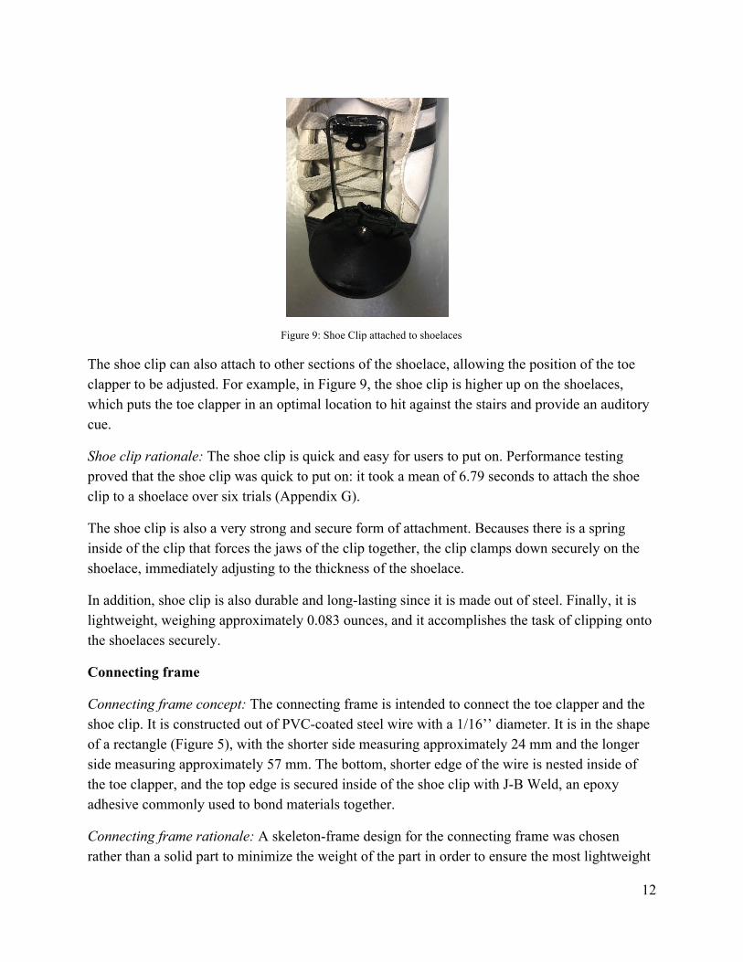
Figure 9: Shoe Clip attached to shoelaces
The shoe clip can also attach to other sections of the shoelace, allowing the position of the toe clapper to be adjusted. For example, in Figure 9, the shoe clip is higher up on the shoelaces, which puts the toe clapper in an optimal location to hit against the stairs and provide an auditory cue.
Shoe clip rationale: The shoe clip is quick and easy for users to put on. Performance testing proved that the shoe clip was quick to put on: it took a mean of 6.79 seconds to attach the shoe clip to a shoelace over six trials (Appendix G).
The shoe clip is also a very strong and secure form of attachment. Becauses there is a spring inside of the clip that forces the jaws of the clip together, the clip clamps down securely on the shoelace, immediately adjusting to the thickness of the shoelace.
In addition, shoe clip is also durable and long-lasting since it is made out of steel. Finally, it is lightweight, weighing approximately 0.083 ounces, and it accomplishes the task of clipping onto the shoelaces securely.
Connecting frame
Connecting frame concept: The connecting frame is intended to connect the toe clapper and the shoe clip. It is constructed out of PVC-coated steel wire with a 1/16’’ diameter. It is in the shape of a rectangle (Figure 5), with the shorter side measuring approximately 24 mm and the longer side measuring approximately 57 mm. The bottom, shorter edge of the wire is nested inside of the toe clapper, and the top edge is secured inside of the shoe clip with J-B Weld, an epoxy adhesive commonly used to bond materials together.
Connecting frame rationale: A skeleton-frame design for the connecting frame was chosen rather than a solid part to minimize the weight of the part in order to ensure the most lightweight
12
possible design. In addition, the frame has additional flexibility since steel wire is more bendable than a solid sheet of metal. This allows the connecting frame to flex with the foot’s movements, which is more ergonomic and reduces user discomfort by not digging into the shoe.
Since the shorter side of the connecting frame attaches to the shoe clip, the length of the shorter side matches up to the width of the shoe clip (Figure 5). The shorter side measures approximately 21mm while the width of the shoe clip is approximately 24 mm. This allows an extra 1.5 mm allowance of wire on both sides of the clip to allow the clip to open and close without touching the wire (Figure 8).
Based on user testing, it was determined that 50-60 mm was an ideal length for the longer side of the connecting frame in order to correctly position the toe clapper over the toe (Appendix F).
The two metals that were top contenders for use in constructing the frame were steel wire and aluminum wire, both cheap, easily-available wires commonly used in construction. Both are strong metals; however, aluminum was too pliable in comparison to steel. In addition, steel is lightweight, durable, and inexpensive. PVC coating steel wire was chosen over regular steel wire because it has a more finished look and the coating adds protection from water and other forces that could potentially come in contact with the steel.
Further Development
The following steps are recommended to develop the design further. At the moment, the device is tailored towards Carlos; however, if there are more users who wish to incorporate this device into their physical therapy, more development is suggested to ensure the device is universally applicable.
Further Testing
User testing: The device was tested on the user at the Shirley Ryan Ability Lab in Chicago. Further testing may include having the user walk for further distances and climb up more stairs, since the length of the user testing was constrained to an hour. Testing the device on multiple users could provide more perspective on the device and different opinions, along with more insight to the quality and durability of the design. For example, decibel meters could be placed near multiple users during the testing to give quantifiable data for the loudness of the device. This could help ensure that the auditory cue is loud enough for many users, and not just Carlos. This would be helpful if the device is to be used with users other than Carlos in the future.
13
Performance testing: A team member wears the device and strikes a stair for a prolonged period of time to simulate the stresses of training that the device could go through. Team members simulate falling or striking the stairs at odd angles to uncover how the device handles these stresses. The device is handled roughly with the intention of uncovering any weaknesses in the design. Testing with a better noise measuring device could yield better results of the volume of the device.
Improvements to the design
Currently, there is one prototype of the device, intended specifically for Carlos. If a market for the device is found, and the client or another team wishes to mass produce this design in the future, then here are a few recommendations for improvements:
Attaching the shoe clip and connecting frame: With the current design, J-B weld is used to attach the shoe clip and connecting frame. While this does provide a stable attachment method, this may be inefficient in a manufacturing setting. Future teams could experiment with welding or manufacturing a connecting frame that already has the shoe clip attached on one side.
Improving audio cue: Finding a way to amplify the sound will be an improvement. As the toe clapper is a standard repurposed castanet, the size and shape have been predetermined; there is much more flexibility in the minutia of the toe clapper itself if it is to be mass produced. For example, a team could experiment with different sizes of the toe clapper to maximize the volume of the auditory cue. At the same time, future teams should avoid an oversized toe clapper that could cause unwieldiness on the shoe.
Conclusion
To summarize, the design of the Clipper Clapper meets the key needs of the user, as well as project constraints and requirements. The design includes the following four components:
● ¾’’ steel shoe clip: to simplify the process of putting the device on, a way of securing the device to the shoe and allowing the placement of the device to be adjustable based on the size of the shoe and the comfort of the user
● 1/16’’ PVC-coated steel wire connecting frame: to add enough flexibility so the device can adjust to foot movement, but also enough stability so it does not break or bend permanently
● Wooden toe clapper: to provide a loud enough auditory cue to effectively notify the user when they are hitting the stairs
14
● 1-inch wide elastic stretchable shoe attachment: to secure the device to the front of the shoe in order to limit movement of the device.
Despite having all four of these components, the design is lightweight enough to avoid impeding the gait of the user. The majority of the weight comes from the toe clapper, which is only 0.705 ounces. In addition, the majority of the device sits on the top of the shoe so it does not pose a tripping risk.
The device is safe for the user to use, as the combination of the elastic and the clip provide multiple support points on the shoe. The elastic band on the bottom is not slippery and has traction so that the user does not slip. It’s only made for one foot so that the user has stability with the other foot. In addition, the durability of the elastic means that the design can be used as a therapy device for multiple hours. The wire used allows the device to be flexible and adjustable. It also fulfills the requirement for ease-of-use as both parts only require a few seconds to put on.
Additionally, the design does not include any electronics, wiring or complex parts that would make it difficult to use or fix if something broke. It falls under the minimum cost of $100, as the toe clapper, steel wire, shoe clip, and elastic were all inexpensive and readily available. The design is straightforward and has replaceable, affordable and familiar parts. The toe clapper produces a sounds loud enough to alert the user. Most importantly, the familiarity of the toe clapper to the user will allow the user to build on previous biofeedback therapy involving the toe clapper, paving the way for future progress.
References
American Association of Neurological Surgeons. “Spasticity”. American Association of
Neurological Surgeons, n.d. Web. 20 September 2017.
American Optometric Association. “Strabismus (Crossed Eyes)”. American Optometric
Association, n.d. Web. 20 September 2017.
Davis, Annette M., et al. “Effect of footwear on minimum foot clearance, heel slippage and
spatiotemporal measures of gait in older women.” Gait Posture. 2016 Feb; 44: 43–47.
Web. 28 Oct. 2017. www.ncbi.nlm.nih.gov/pubmed/27004631
15
Dadashi, Farzin. “Gait and Foot Clearance Parameters Obtained Using Shoe-Worn Inertial
Sensors in a Large-Population Sample of Older Adults.” Sensors (Basel, Switzerland)
14.1 (2014): 443–457. PMC. Web. 28 Oct. 2017.
www.ncbi.nlm.nih.gov/pmc/articles/PMC3926567/
De La Torre Orthotics and Prosthetics. “AFO, Ankle Foot Orthosis, Floor Reaction
(Custom-Molded)”. De La Torre Orthotics and Prosthetics, n.d. Web. 20 September
2017.
Lewerenz, Annika, et al. “Mechanisms to improve foot clearance while stair ascending in
patients with bilateral spastic cerebral palsy and stiff knee gait.” Gait & Posture. 57.1
(2017): 60-61. Print.
Mayo Clinic Staff. “Cerebral Palsy”. Mayo Foundation for Medical Education and Research,
n.d. Web. 20 September 2017.
Miller, Denice. Personal Communication. 4 October 2017.
My Child. “Types of Cerebral Palsy”. My Child at Cerebral Palsy, n.d. Web. 20 September
2017.
Novak, Alison C., et al. “Stair Negotiation Alters Stability in Older Adults.” Lower Extremity
Review Magazine, LER Magazine, 2010,
www.lermagazine.com/article/stair-negotiation-alters-stability-in-older-adults.
Rosenbaum , Peter L, et al. “Development of the Gross Motor Function Classification System for
Cerebral Palsy”. Developmental Medicine and Child Neurology. 39 (3 March 2008):214-223.
Web.
16
Wallender, Lee. “Learn These Code Requirements for Stairs.” The Spruce, 3 Mar. 2017. Web. 28
Oct. 2017.
www.thespruce.com/code-requirements-risers-treads-stair-width-and-more-4120151
APPENDIX A: PROJECT DEFINITION
After user observation and analysis of the problem, goals were set for the end design to achieve. The project definition lays out those goals and was created to help keep the team aligned and focused throughout the design process. Project Name: The Clipper Clapper Client: Gabby Marquez, Shirley Ryan Ability Lab Team Members: Caitlin Draper, Elise Lee, Steven Han Date: October 7, 2017
Mission Statement: To create an easy-to-use therapeutic aid for Carlos, an eighteen-year old male with cerebral palsy, to aid him with ascending stairs without limiting his walking ability, with the goal of preventing his foot from hitting the front of the stairs.
Project Deliverables: A working full-size model or example of the therapeutic aid.
Constraints ● Must fall under budget ($100 max) ● Cannot interfere with his gait
Users/stakeholders
17
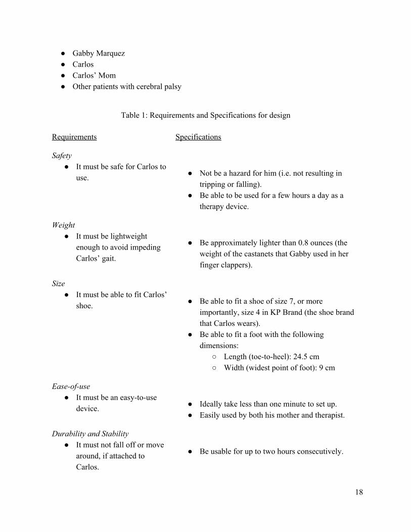
● Gabby Marquez ● Carlos ● Carlos’ Mom ● Other patients with cerebral palsy
Table 1: Requirements and Specifications for design
Requirements Specifications
Safety ● It must be safe for Carlos to
use.
● Not be a hazard for him (i.e. not resulting in tripping or falling).
● Be able to be used for a few hours a day as a therapy device.
Weight ● It must be lightweight
enough to avoid impeding Carlos’ gait.
● Be approximately lighter than 0.8 ounces (the weight of the castanets that Gabby used in her finger clappers).
Size ● It must be able to fit Carlos’
shoe.
● Be able to fit a shoe of size 7, or more importantly, size 4 in KP Brand (the shoe brand that Carlos wears).
● Be able to fit a foot with the following dimensions:
○ Length (toe-to-heel): 24.5 cm ○ Width (widest point of foot): 9 cm
Ease-of-use ● It must be an easy-to-use
device.
● Ideally take less than one minute to set up. ● Easily used by both his mother and therapist.
Durability and Stability ● It must not fall off or move
around, if attached to Carlos.
● Be usable for up to two hours consecutively.
18
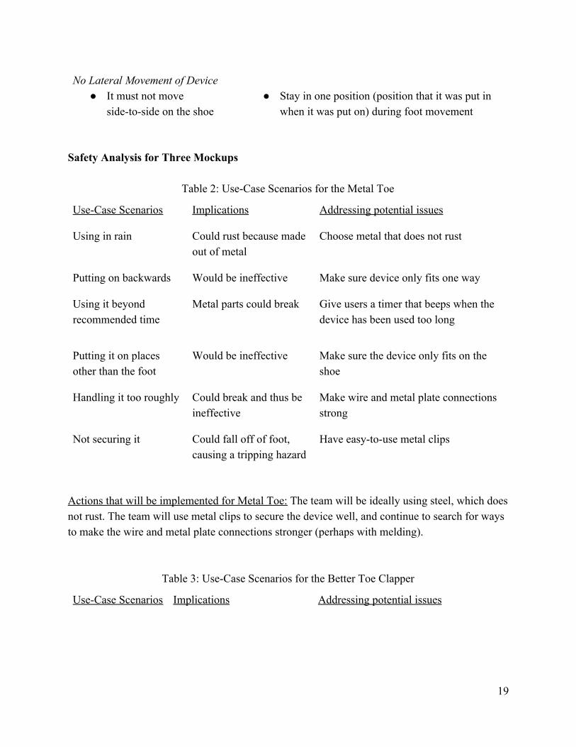
No Lateral Movement of Device ● It must not move
side-to-side on the shoe
● Stay in one position (position that it was put in
when it was put on) during foot movement
Safety Analysis for Three Mockups
Table 2: Use-Case Scenarios for the Metal Toe
Use-Case Scenarios Implications Addressing potential issues
Using in rain Could rust because made out of metal
Choose metal that does not rust
Putting on backwards Would be ineffective Make sure device only fits one way
Using it beyond recommended time
Metal parts could break Give users a timer that beeps when the device has been used too long
Putting it on places other than the foot
Would be ineffective Make sure the device only fits on the shoe
Handling it too roughly Could break and thus be ineffective
Make wire and metal plate connections strong
Not securing it Could fall off of foot, causing a tripping hazard
Have easy-to-use metal clips
Actions that will be implemented for Metal Toe: The team will be ideally using steel, which does not rust. The team will use metal clips to secure the device well, and continue to search for ways to make the wire and metal plate connections stronger (perhaps with melding).
Table 3: Use-Case Scenarios for the Better Toe Clapper
Use-Case Scenarios Implications Addressing potential issues
19
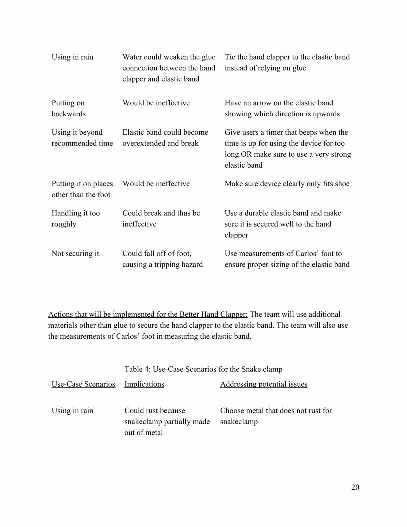
Using in rain Water could weaken the glue connection between the hand clapper and elastic band
Tie the hand clapper to the elastic band instead of relying on glue
Putting on backwards
Would be ineffective Have an arrow on the elastic band showing which direction is upwards
Using it beyond recommended time
Elastic band could become overextended and break
Give users a timer that beeps when the time is up for using the device for too long OR make sure to use a very strong elastic band
Putting it on places other than the foot
Would be ineffective Make sure device clearly only fits shoe
Handling it too roughly
Could break and thus be ineffective
Use a durable elastic band and make sure it is secured well to the hand clapper
Not securing it Could fall off of foot, causing a tripping hazard
Use measurements of Carlos’ foot to ensure proper sizing of the elastic band
Actions that will be implemented for the Better Hand Clapper: The team will use additional materials other than glue to secure the hand clapper to the elastic band. The team will also use the measurements of Carlos’ foot in measuring the elastic band.
Table 4: Use-Case Scenarios for the Snake clamp
Use-Case Scenarios Implications Addressing potential issues
Using in rain Could rust because snakeclamp partially made out of metal
Choose metal that does not rust for snakeclamp
20
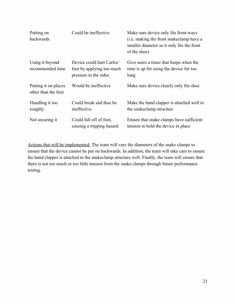
Putting on backwards
Could be ineffective Make sure device only fits front-ways (i.e. making the front snakeclamp have a smaller diameter so it only fits the front of the shoe)
Using it beyond recommended time
Device could hurt Carlos’ foot by applying too much pressure to the sides
Give users a timer that beeps when the time is up for using the device for too long
Putting it on places other than the foot
Would be ineffective Make sure device clearly only fits shoe
Handling it too roughly
Could break and thus be ineffective
Make the hand clapper is attached well to the snakeclamp structure
Not securing it Could fall off of foot, causing a tripping hazard
Ensure that snake clamps have sufficient tension to hold the device in place
Actions that will be implemented: The team will vary the diameters of the snake clamps to ensure that the device cannot be put on backwards. In addition, the team will take care to ensure the hand clapper is attached to the snakeclamp structure well. Finally, the team will ensure that there is not too much or too little tension from the snake clamps through future performance testing.
21
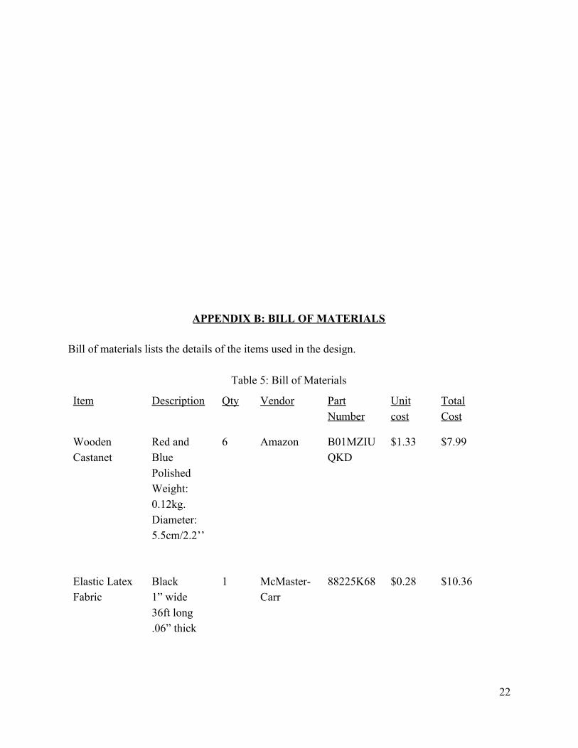
APPENDIX B: BILL OF MATERIALS Bill of materials lists the details of the items used in the design.
Table 5: Bill of Materials
Item Description Qty Vendor Part Number
Unit cost
Total Cost
Wooden Castanet
Red and Blue Polished Weight: 0.12kg. Diameter: 5.5cm/2.2’’
6 Amazon B01MZIUQKD
$1.33 $7.99
Elastic Latex Fabric
Black 1” wide 36ft long .06” thick
1 McMaster-Carr
88225K68 $0.28 $10.36
22
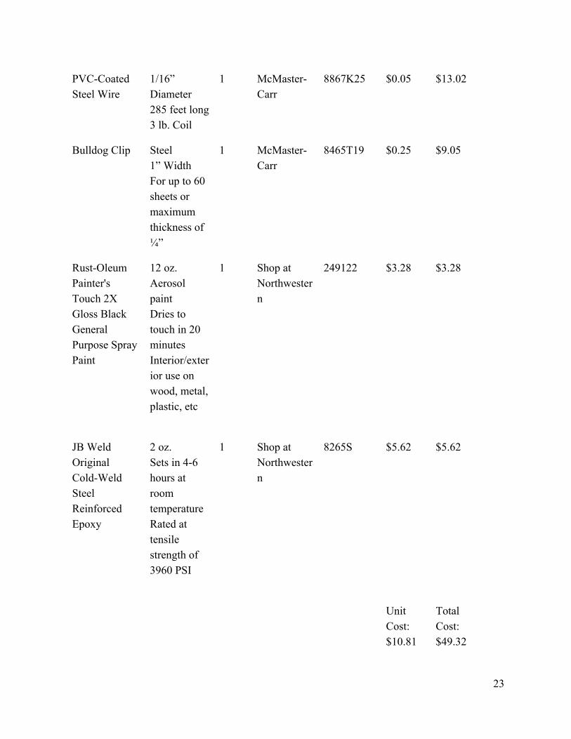
PVC-Coated Steel Wire
1/16” Diameter 285 feet long 3 lb. Coil
1 McMaster-Carr
8867K25 $0.05 $13.02
Bulldog Clip Steel 1” Width For up to 60 sheets or maximum thickness of ¼”
1 McMaster-Carr
8465T19 $0.25 $9.05
Rust-Oleum Painter's Touch 2X Gloss Black General Purpose Spray Paint
12 oz. Aerosol paint Dries to touch in 20 minutes Interior/exterior use on wood, metal, plastic, etc
1 Shop at Northwestern
249122 $3.28 $3.28
JB Weld Original Cold-Weld Steel Reinforced Epoxy
2 oz. Sets in 4-6 hours at room temperature Rated at tensile strength of 3960 PSI
1 Shop at Northwestern
8265S $5.62 $5.62
Unit Cost: $10.81
Total Cost: $49.32
23
The castanets were bought by the team. The elastic latex fabric, bulldog clip, and the wire were purchased by Northwestern.
APPENDIX C: BACKGROUND RESEARCH Background research was conducted to better understand the problem. It includes insight into our user, his condition and the situation that called for a new device to be designed. After receiving preliminary information about the design from the client, a physical therapist at the Shirley Ryan Ability lab, the team conducted background research to better understand the situation. The problem is people with visual and cognitive deficits have difficulty climbing stairs due to insufficient step clearance. In addition, there is a lack of therapy products to help rehabilitate patients. The therapist shared her workaround solution, which was a biofeedback device involving a castanet taped to the front of the shoe. The background research is divided into three categories: minimum foot clearance, existing remedies to solve problems relating to foot clearance, client-based research about cerebral palsy, and stair research.
Minimum Foot Clearance (MFC) on Stairs
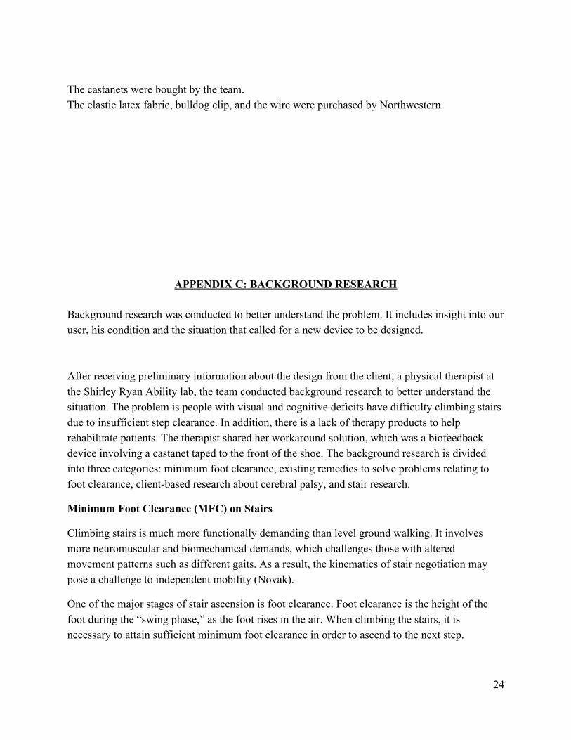
Climbing stairs is much more functionally demanding than level ground walking. It involves more neuromuscular and biomechanical demands, which challenges those with altered movement patterns such as different gaits. As a result, the kinematics of stair negotiation may pose a challenge to independent mobility (Novak).
One of the major stages of stair ascension is foot clearance. Foot clearance is the height of the foot during the “swing phase,” as the foot rises in the air. When climbing the stairs, it is necessary to attain sufficient minimum foot clearance in order to ascend to the next step.
24
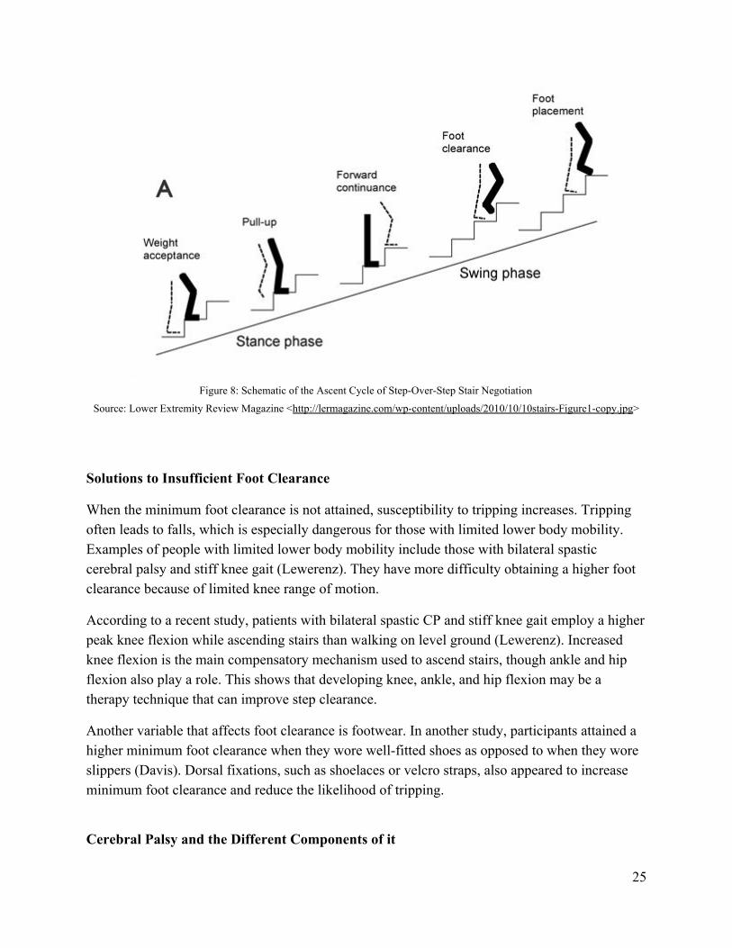
Figure 8: Schematic of the Ascent Cycle of Step-Over-Step Stair Negotiation
Source: Lower Extremity Review Magazine <http://lermagazine.com/wp-content/uploads/2010/10/10stairs-Figure1-copy.jpg>
Solutions to Insufficient Foot Clearance
When the minimum foot clearance is not attained, susceptibility to tripping increases. Tripping often leads to falls, which is especially dangerous for those with limited lower body mobility. Examples of people with limited lower body mobility include those with bilateral spastic cerebral palsy and stiff knee gait (Lewerenz). They have more difficulty obtaining a higher foot clearance because of limited knee range of motion.
According to a recent study, patients with bilateral spastic CP and stiff knee gait employ a higher peak knee flexion while ascending stairs than walking on level ground (Lewerenz). Increased knee flexion is the main compensatory mechanism used to ascend stairs, though ankle and hip flexion also play a role. This shows that developing knee, ankle, and hip flexion may be a therapy technique that can improve step clearance.
Another variable that affects foot clearance is footwear. In another study, participants attained a higher minimum foot clearance when they wore well-fitted shoes as opposed to when they wore slippers (Davis). Dorsal fixations, such as shoelaces or velcro straps, also appeared to increase minimum foot clearance and reduce the likelihood of tripping.
Cerebral Palsy and the Different Components of it
25
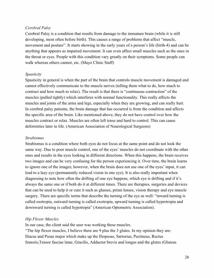
Cerebral Palsy Cerebral Palsy is a condition that results from damage to the immature brain (while it is still developing, most often before birth). This causes a range of problems that affect “muscle, movement and posture”. It starts showing in the early years of a person’s life (birth-4) and can be anything that appears as impaired movement. It can even affect small muscles such as the ones in the throat or eyes. People with this condition vary greatly on their symptoms. Some people can walk whereas others cannot, etc. (Mayo Clinic Staff) Spasticity Spasticity in general is when the part of the brain that controls muscle movement is damaged and cannot effectively communicate to the muscle nerves (telling them what to do, how much to contract and how much to relax). The result is that there is “continuous contraction” of the muscles (pulled tightly) which interferes with normal functionality. This really affects the muscles and joints of the arms and legs, especially when they are growing, and can really hurt. In cerebral palsy patients, the brain damage that has occurred is from the condition and affects the specific area of the brain. Like mentioned above, they do not have control over how the muscles contract or relax. Muscles are often left tense and hard to control. This can cause deformities later in life. (American Association of Neurological Surgeons) Strabismus Strabismus is a condition where both eyes do not focus at the same point and do not look the same way. Due to poor muscle control, one of the eyes’ muscles do not coordinate with the other ones and results in the eyes looking in different directions. When this happens, the brain receives two images and can be very confusing for the person experiencing it. Over time, the brain learns to ignore one of the images; however, when the brain does not use one of the eyes’ input, it can lead to a lazy eye (permanently reduced vision in one eye). It is also really important when diagnosing to note how often the drifting of one eye happens, which eye is drifting and if it’s always the same one or if both do it at different times. There are therapies, surgeries and devices that can be used to help it or cure it such as glasses, prism lenses, vision therapy and eye muscle surgery. There are specific terms that describe the turning of the eye as well: “inward turning is called esotropia, outward turning is called exotropia, upward turning is called hypertropia and downward turning is called hypotropia” (American Optometric Association). Hip Flexor Muscles In our case, the client said the user was working these muscles. “The hip flexor muscles, I believe there are 9 plus the 3 glutes. In my opinion they are: Iliacus and Psoas major which make up the Iliopsoas, Sartorius, Pectineus, Rectus femoris,Tensor fasciae latae, Gracilis, Adductor brevis and longus and the glutes (Gluteus
26
maximus, minimus, medius) (Miller)”. Ms. Miller is an Anatomy and Physiology teacher and Mountain Pointe High School.
<”Adductors” , Redbox Fitness, Bing> <”Gluteus Muscles”, Modesto Junior College, Bing> Levels of describing cerebral palsy Levels are hard to describe because there are so many varieties of cerebral palsy. The severity can be described by gross motor skills, fine motor skills (manual ability), topographical distribution and/or communication skills. Gross motor skills includes things like walking and moving the arms, legs and the head. Fine motor skills have to do with the fingers and making small muscle movements; handling objects. Topographical location describes what body parts are affected (My Child). Communication skills are how the person communicates and how effective it is. Gross motor skill levels are on a scale from 1-5; a 1 describes a patient who is not very limited, they can walk and climb stairs without help and they might have slight issues with coordination and balance. Level 2 is someone who can walk but might have troubled if there are obstacles or if they have to walk for long periods of time; also, they might need assistance with some more arduous tasks and have minimal ability to run and jump. A person in the level 3 range would use assistance (such as a walker) when walking and an aid when climbing stairs. When they have to go long distances, they might use a wheelchair. Level 4 described a situation where the person mostly uses mobility methods that require assistance (a person with them). Sometimes they practice walking with help but the main method outside (like in school) is a wheelchair or
27
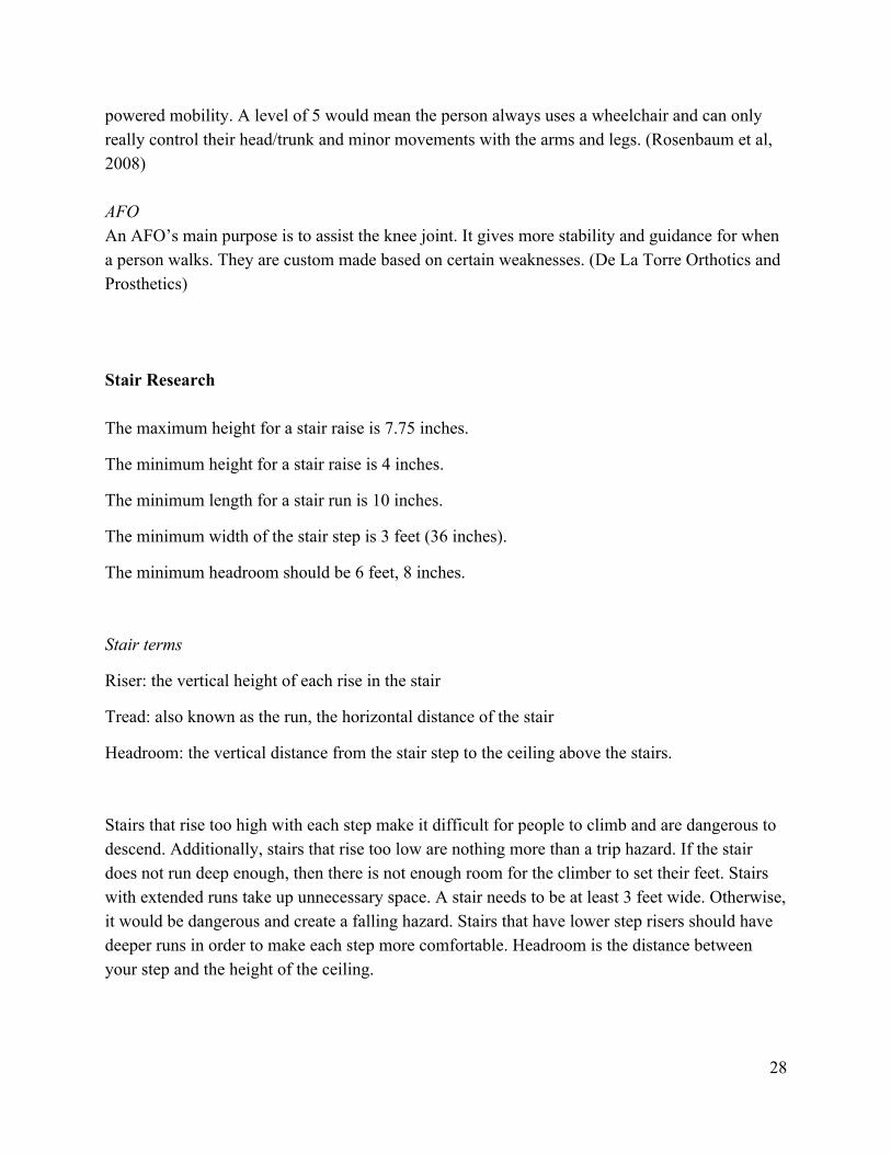
powered mobility. A level of 5 would mean the person always uses a wheelchair and can only really control their head/trunk and minor movements with the arms and legs. (Rosenbaum et al, 2008) AFO An AFO’s main purpose is to assist the knee joint. It gives more stability and guidance for when a person walks. They are custom made based on certain weaknesses. (De La Torre Orthotics and Prosthetics) Stair Research The maximum height for a stair raise is 7.75 inches.
The minimum height for a stair raise is 4 inches.
The minimum length for a stair run is 10 inches.
The minimum width of the stair step is 3 feet (36 inches).
The minimum headroom should be 6 feet, 8 inches.
Stair terms
Riser: the vertical height of each rise in the stair
Tread: also known as the run, the horizontal distance of the stair
Headroom: the vertical distance from the stair step to the ceiling above the stairs.
Stairs that rise too high with each step make it difficult for people to climb and are dangerous to descend. Additionally, stairs that rise too low are nothing more than a trip hazard. If the stair does not run deep enough, then there is not enough room for the climber to set their feet. Stairs with extended runs take up unnecessary space. A stair needs to be at least 3 feet wide. Otherwise, it would be dangerous and create a falling hazard. Stairs that have lower step risers should have deeper runs in order to make each step more comfortable. Headroom is the distance between your step and the height of the ceiling.
28
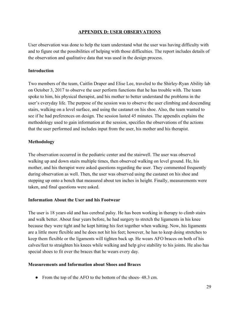
APPENDIX D: USER OBSERVATIONS User observation was done to help the team understand what the user was having difficulty with and to figure out the possibilities of helping with those difficulties. The report includes details of the observation and qualitative data that was used in the design process. Introduction Two members of the team, Caitlin Draper and Elise Lee, traveled to the Shirley-Ryan Ability lab on October 3, 2017 to observe the user perform functions that he has trouble with. The team spoke to him, his physical therapist, and his mother to better understand the problems in the user’s everyday life. The purpose of the session was to observe the user climbing and descending stairs, walking on a level surface, and using the castanet on his shoe. Also, the team wanted to see if he had preferences on design. The session lasted 45 minutes. The appendix explains the methodology used to gain information at the session, specifies the observations of the actions that the user performed and includes input from the user, his mother and his therapist. Methodology The observation occurred in the pediatric center and the stairwell. The user was observed walking up and down stairs multiple times, then observed walking on level ground. He, his mother, and his therapist were asked questions regarding the user. They commented frequently during observation as well. Then, the user was observed using the castanet on his shoe and stepping up onto a bench that measured about ten inches in height. Finally, measurements were taken, and final questions were asked. Information About the User and his Footwear The user is 18 years old and has cerebral palsy. He has been working in therapy to climb stairs and walk better. About four years before, he had surgery to stretch the ligaments in his knee because they were tight and he kept hitting his feet together when walking. Now, his ligaments are a little more flexible and he does not hit his feet; however, he has to keep doing stretches to keep them flexible or the ligaments will tighten back up. He wears AFO braces on both of his calves/feet to straighten his knees while walking and help give stability to his joints. He also has special shoes to fit over the braces that he wears every day. Measurements and Information about Shoes and Braces
● From the top of the AFO to the bottom of the shoes- 48.3 cm.
29
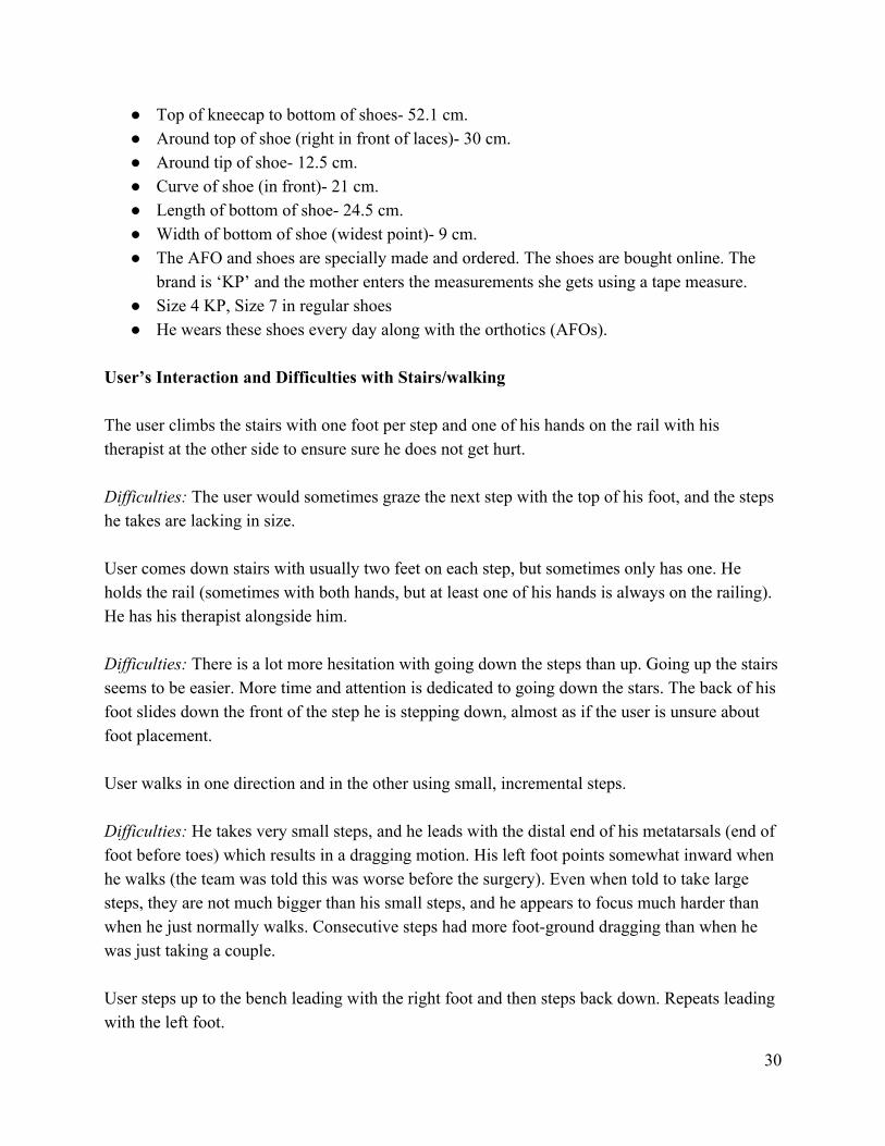
● Top of kneecap to bottom of shoes- 52.1 cm. ● Around top of shoe (right in front of laces)- 30 cm. ● Around tip of shoe- 12.5 cm. ● Curve of shoe (in front)- 21 cm. ● Length of bottom of shoe- 24.5 cm. ● Width of bottom of shoe (widest point)- 9 cm. ● The AFO and shoes are specially made and ordered. The shoes are bought online. The
brand is ‘KP’ and the mother enters the measurements she gets using a tape measure. ● Size 4 KP, Size 7 in regular shoes ● He wears these shoes every day along with the orthotics (AFOs).
User’s Interaction and Difficulties with Stairs/walking The user climbs the stairs with one foot per step and one of his hands on the rail with his therapist at the other side to ensure sure he does not get hurt. Difficulties: The user would sometimes graze the next step with the top of his foot, and the steps he takes are lacking in size. User comes down stairs with usually two feet on each step, but sometimes only has one. He holds the rail (sometimes with both hands, but at least one of his hands is always on the railing). He has his therapist alongside him. Difficulties: There is a lot more hesitation with going down the steps than up. Going up the stairs seems to be easier. More time and attention is dedicated to going down the stars. The back of his foot slides down the front of the step he is stepping down, almost as if the user is unsure about foot placement. User walks in one direction and in the other using small, incremental steps. Difficulties: He takes very small steps, and he leads with the distal end of his metatarsals (end of foot before toes) which results in a dragging motion. His left foot points somewhat inward when he walks (the team was told this was worse before the surgery). Even when told to take large steps, they are not much bigger than his small steps, and he appears to focus much harder than when he just normally walks. Consecutive steps had more foot-ground dragging than when he was just taking a couple. User steps up to the bench leading with the right foot and then steps back down. Repeats leading with the left foot.
30
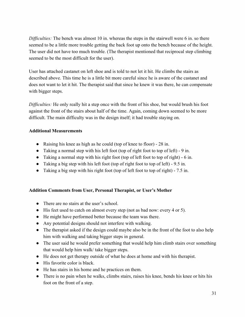
Difficulties: The bench was almost 10 in. whereas the steps in the stairwell were 6 in. so there seemed to be a little more trouble getting the back foot up onto the bench because of the height. The user did not have too much trouble. (The therapist mentioned that reciprocal step climbing seemed to be the most difficult for the user). User has attached castanet on left shoe and is told to not let it hit. He climbs the stairs as described above. This time he is a little bit more careful since he is aware of the castanet and does not want to let it hit. The therapist said that since he knew it was there, he can compensate with bigger steps. Difficulties: He only really hit a step once with the front of his shoe, but would brush his foot against the front of the stairs about half of the time. Again, coming down seemed to be more difficult. The main difficulty was in the design itself; it had trouble staying on. Additional Measurements
● Raising his knee as high as he could (top of knee to floor) - 28 in. ● Taking a normal step with his left foot (top of right foot to top of left) - 9 in. ● Taking a normal step with his right foot (top of left foot to top of right) - 6 in. ● Taking a big step with his left foot (top of right foot to top of left) - 9.5 in. ● Taking a big step with his right foot (top of left foot to top of right) - 7.5 in.
Addition Comments from User, Personal Therapist, or User’s Mother
● There are no stairs at the user’s school. ● His feet used to catch on almost every step (not as bad now: every 4 or 5). ● He might have performed better because the team was there. ● Any potential designs should not interfere with walking. ● The therapist asked if the design could maybe also be in the front of the foot to also help
him with walking and taking bigger steps in general. ● The user said he would prefer something that would help him climb stairs over something
that would help him walk/ take bigger steps. ● He does not get therapy outside of what he does at home and with his therapist. ● His favorite color is black. ● He has stairs in his home and he practices on them. ● There is no pain when he walks, climbs stairs, raises his knee, bends his knee or hits his
foot on the front of a step.
31
● The user feels that his left and right legs are equally strong. ● He does stretches at night to keep his ligaments flexible and to gain more flexibility;
stretching is the only thing that the user said can be bothersome.
32
APPENDIX E: MOCKUPS
This section includes the mockups that were made and details of each one.
Description of each mockup tested
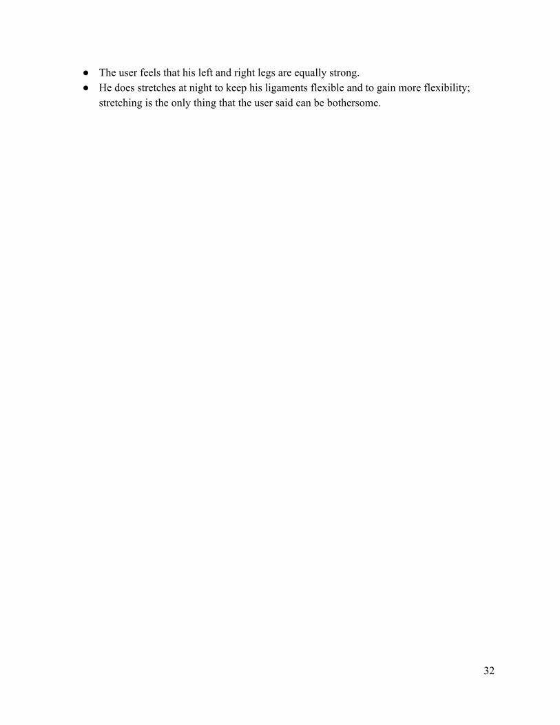
Figure 9: Metal Toe
Two sheets of metal are attached to a piece of wire and a bulldog clip. The bulldog clip allows the contraption to be easily attached to the user’s shoe. As the user moves his/her foot, the piece of metal will hit against the other one and create a noise.
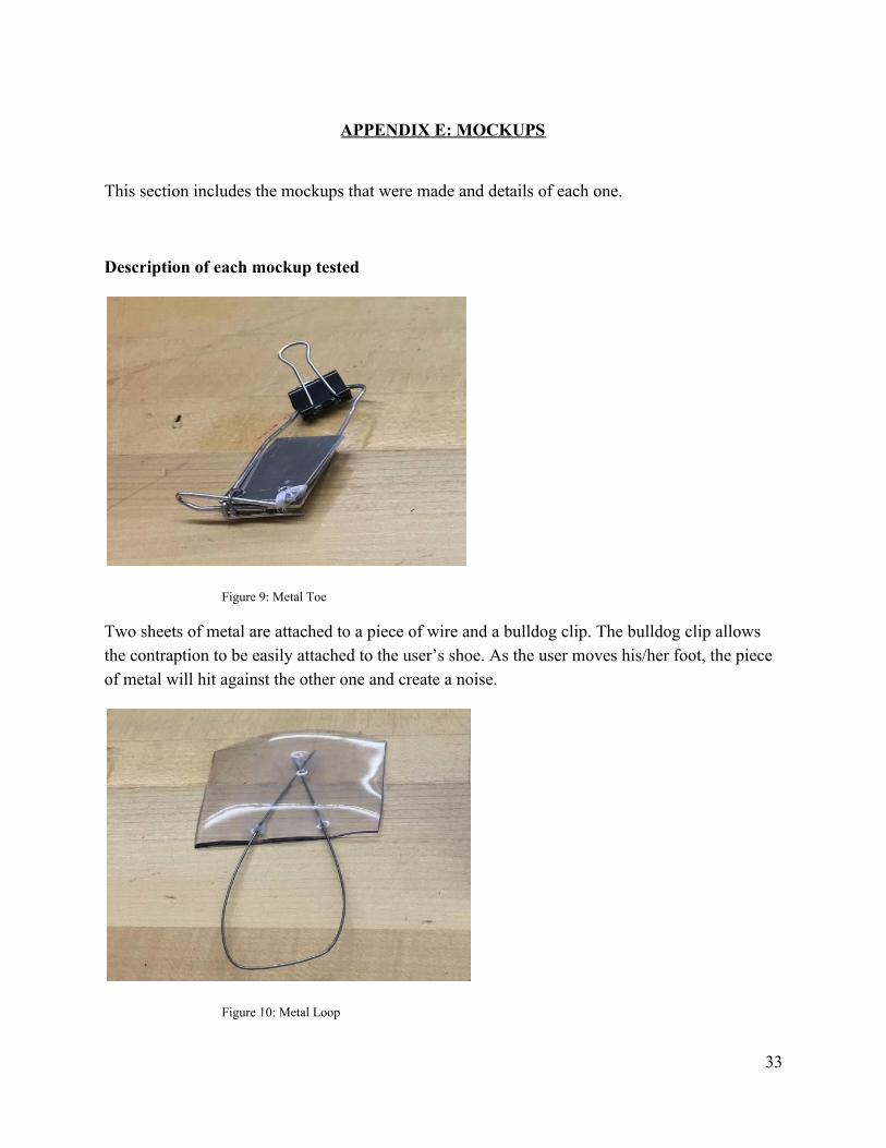
Figure 10: Metal Loop
33
A piece of wire that is bended in a loop and piece of plastic is attached to it. The piece of plastic can be placed inside the front part of the user’s shoe. The wire extends out and you can attach a castanet (hand-clapper) not shown, to the loop of the wire.
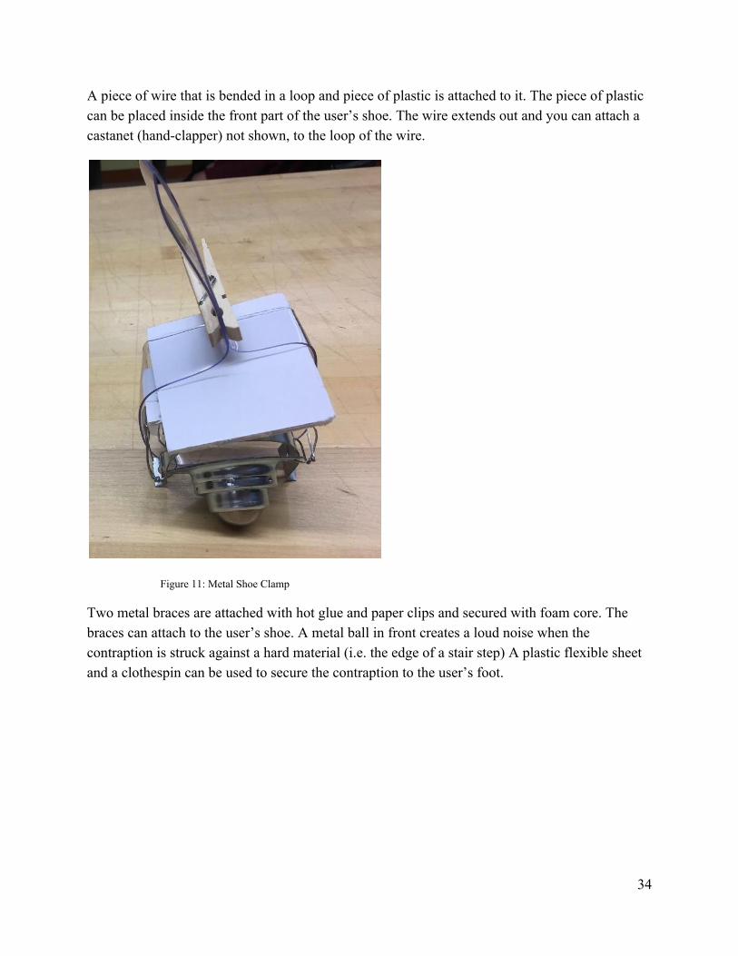
Figure 11: Metal Shoe Clamp
Two metal braces are attached with hot glue and paper clips and secured with foam core. The braces can attach to the user’s shoe. A metal ball in front creates a loud noise when the contraption is struck against a hard material (i.e. the edge of a stair step) A plastic flexible sheet and a clothespin can be used to secure the contraption to the user’s foot.
34
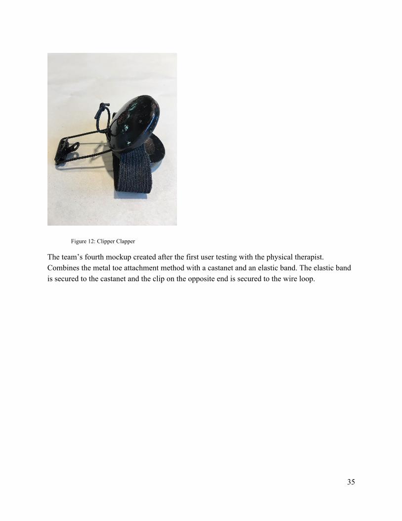
Figure 12: Clipper Clapper
The team’s fourth mockup created after the first user testing with the physical therapist. Combines the metal toe attachment method with a castanet and an elastic band. The elastic band is secured to the castanet and the clip on the opposite end is secured to the wire loop.
35
APPENDIX F: USER TESTING REPORT User testing includes the details and data of when the four mockups were tried by the user. This data was used in the design process, specifically with the final design.
Purpose
The purpose of testing was to determine the best mockup for an 18-year-old with cerebral palsy. The team initially developed three mockups that fit the requirements of cost, ease of use and safety. After the first user testing, the team developed an additional mockup (Figure 12). Additionally, each mockup is worn on the foot and creates an auditory cue whenever the user strikes the ledge of a stair step. The team desired to test which mockup would be the most effective in creating noise, staying on the user’s shoe and quickest to put on. The team’s initial mockups are (1) a clip to the shoe that holds two sheets of metal, one rigid and one loose, that will strike a nail and make an auditory cue when the user strikes the edge of the stairs (Figure 9). (2) A device that attaches to the shoe through the form of a bent wire and piece of flexible plastic. A castanet can be attached to the metal loop (Figure 10). (3) A mockup that used a springy metal brace to attach to the shoe and would create a loud noise when striking the stair step (Figure 11).
Test methodology
Two user testing sessions were performed. During the first session, the user’s physical therapist, Gabby, tested the device. She was asked to put each of the mockups on her shoe as they were all made to attach on a shoe. She would ascend a flight of stairs several times and make comments on the mockups. Comments included (1) how loud the mockup was, (2) any signs of discomfort or pressure caused by the mockup (3) if the mockup was too heavy (4) If the mockup was dangerous for the user. The user’s physical therapist was questioned on each of those topics after testing the mockup and her remarks were recorded. For the second testing session, the distance from the front of the elastic to the tip of the user’s shoe was measured and recorded for 0, 5 and 10 steps on level ground and for 13 steps of a flight of stairs. The distance from the right edge of the wire loop to the right edge of the user’s shoe was also recorded for the above distances. The purpose of these measurements was to test shifting. The user was also questioned on any feelings of pain, heaviness of the mockup and ease of walking. The user was video recorded during these tests.
36
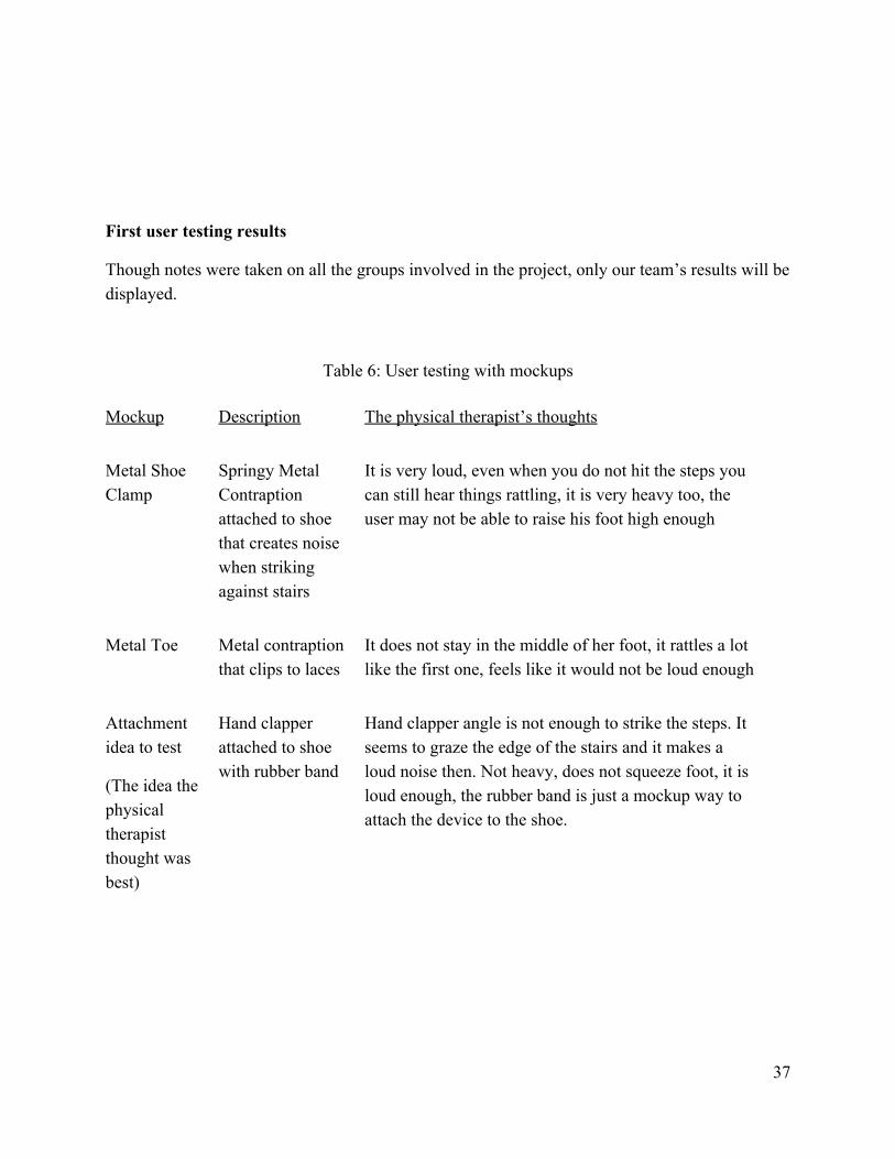
First user testing results
Though notes were taken on all the groups involved in the project, only our team’s results will be displayed.
Table 6: User testing with mockups
Mockup Description The physical therapist’s thoughts
Metal Shoe Clamp
Springy Metal Contraption attached to shoe that creates noise when striking against stairs
It is very loud, even when you do not hit the steps you can still hear things rattling, it is very heavy too, the user may not be able to raise his foot high enough
Metal Toe Metal contraption that clips to laces
It does not stay in the middle of her foot, it rattles a lot like the first one, feels like it would not be loud enough
Attachment idea to test
(The idea the physical therapist thought was best)
Hand clapper attached to shoe with rubber band
Hand clapper angle is not enough to strike the steps. It seems to graze the edge of the stairs and it makes a loud noise then. Not heavy, does not squeeze foot, it is loud enough, the rubber band is just a mockup way to attach the device to the shoe.
37
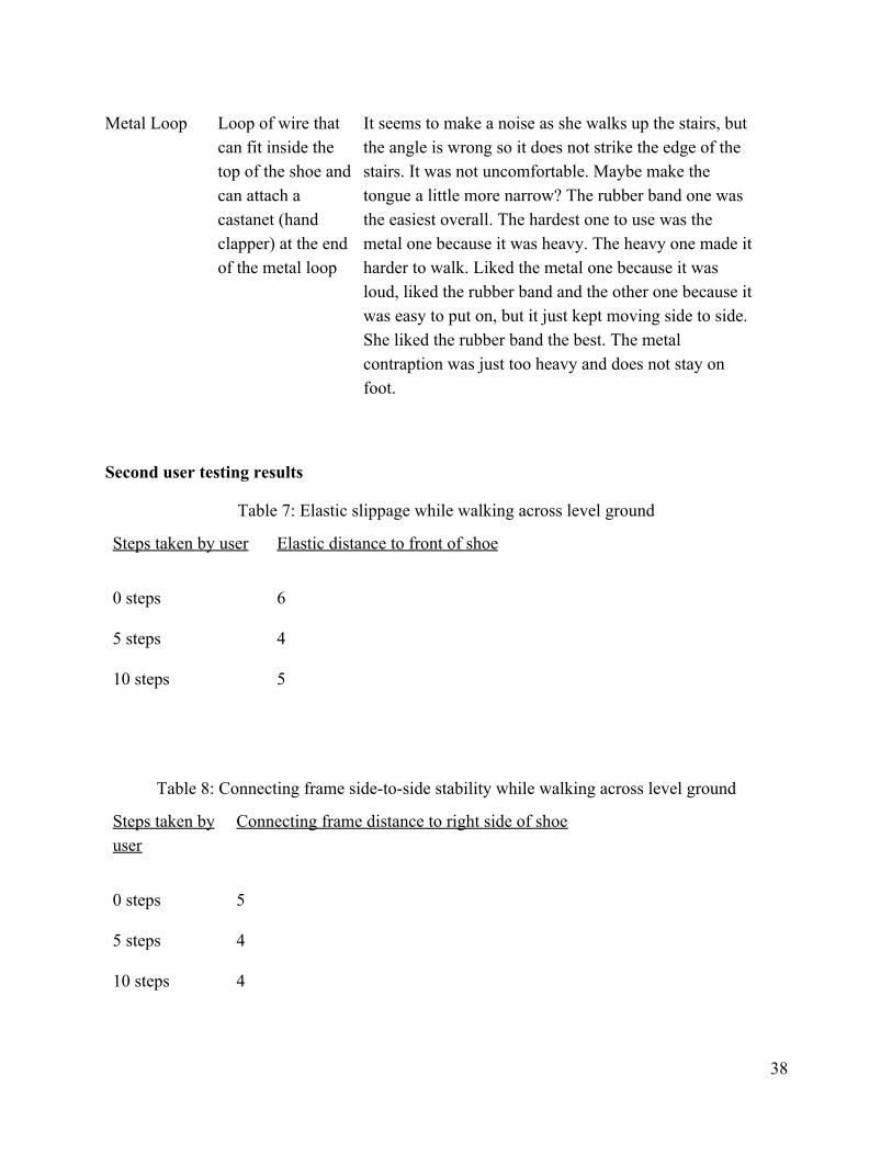
Metal Loop Loop of wire that can fit inside the top of the shoe and can attach a castanet (hand clapper) at the end of the metal loop
It seems to make a noise as she walks up the stairs, but the angle is wrong so it does not strike the edge of the stairs. It was not uncomfortable. Maybe make the tongue a little more narrow? The rubber band one was the easiest overall. The hardest one to use was the metal one because it was heavy. The heavy one made it harder to walk. Liked the metal one because it was loud, liked the rubber band and the other one because it was easy to put on, but it just kept moving side to side. She liked the rubber band the best. The metal contraption was just too heavy and does not stay on foot.
Second user testing results
Table 7: Elastic slippage while walking across level ground
Steps taken by user Elastic distance to front of shoe
0 steps 6
5 steps 4
10 steps 5
Table 8: Connecting frame side-to-side stability while walking across level ground
Steps taken by user
Connecting frame distance to right side of shoe
0 steps 5
5 steps 4
10 steps 4
38
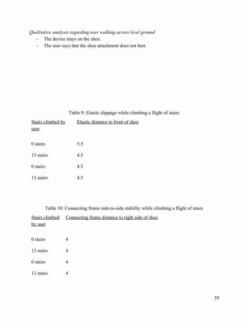
Qualitative analysis regarding user walking across level ground - The device stays on the shoe. - The user says that the shoe attachment does not hurt.
Table 9: Elastic slippage while climbing a flight of stairs
Stairs climbed by user
Elastic distance to front of shoe
0 stairs 5.5
13 stairs 4.5
0 stairs 4.5
13 stairs 4.5
Table 10: Connecting frame side-to-side stability while climbing a flight of stairs
Stairs climbed by user
Connecting frame distance to right side of shoe
0 stairs 4
13 stairs 4
0 stairs 4
13 stairs 4
39
Qualitative analysis regarding user climbing a flight of stairs - The device stays on the shoe. - The user says that the cue is audible.
Analysis of Results
The user’s physical therapist said she liked the rubber band attachment the best. She also believed that having the two sheets of metal that would strike against each other was ideal. She also liked how the contraption can be quickly attached onto the shoe with a bulldog clip. She thought it would take too long to put on the loop of wire inside the front part of the shoe but she liked the attachment idea nonetheless. She disliked the idea of the metal contraption with metal braces to the foot because she thought it was too heavy and it fell off easily. She did say it was the loudest of all of them and she liked how it would provide a very good audio cue. The team agreed with her feedback. The team thought the Metal shoe clamp would be difficult to keep attached and that the rubber band attachment method was a viable option. The team agreed with the physical therapist about the Metal Toe and how it can be easily attached. The team may not have chosen the rubber band attachment because the castanet would not strike the steps directly but Gabby thought it was fine. The team would put more of their efforts on the Metal Toe then the rubber band attachment method that the physical therapist liked best but would attempt to implement both ideas together.
After second user testing, the team determined that the Clipper Clapper shifted very little during each test and the device should be able to stay on the user’s shoe for an extended period of time. The elastic band attachment worked very well. Something to change would be to make the length of the metal loop shorter as it sat a little high on the user’s shoe. The clip worked well to keep the loop attached.
Conclusion
After initial user testing, the team will be creating further mockups for two of the ideas that the physical therapist liked. The rubber band attachment idea and the loop of wire with two metal sheets attached to the end. The team plans to purchase stretchy bands to use in replace of the rubber band. It would be provide better securement of the contraption onto the shoe. The team
40
will test this with a castanet and determine the best way to attach the castanet with the elastic band to the user’s shoe. The team will also create another mockup of the two metal sheets attached with a wire. The team will look for a more professional way to attach the contraption to the user’s shoe other than using a bulldog clip. The team will determine how to stop the wire from moving side to side. The team will determine the measurements of the wire and the sheet metal. The team will determine the best angles to attach the metal sheets to the shoe so they will strike well against the stairs.
Now after second user testing, the team decided to make the length of the metal loop shorter, probably to around 50-60mm due to measurements taken of the patient’s shoe. The team will continue to improve the materials used in the device.
Limitations
The user was unable to show up for the initial user testing. The user showed up for second user testing, but physical therapist present was different from the physical therapist from the first user testing.
41
APPENDIX G: PERFORMANCE TESTING RESULTS
Performance testing was done by the group to further test the mockups and deduce which one would be used for the final design. The most important attributes (according to what we decided) were tested to determine what would go into the final. Purpose
There are many ways to create a contraption that will attach to a shoe and provide audio cues. After performance testing, the team decided that all four ideas were viable options and to test all three at user testing. The team will be testing time required to attach the mockup, how loud the mockup is (its effectiveness in creating an audio cue), and how many steps the mockup stays on (How effective the attachment method is).
Methodology
The team met at a staircase in Northwestern University’s Ford Motor Design Center. To begin, the team timed how long it took to put on the mockup. The team took six trials for each mockup. Then the results would be averaged. Then, one of the team members would attach the mockup to their right shoe. Then the team member would walk up two flights of stairs, which was 16 steps. The team would record the number of steps the mockup stayed on. If the mockup does not fall off completely, but becomes so detached stepping forward would damage it, then it is counted as fallen off. The team repeated this test three times for each of the mockups. Finally, the team would strike the each step with each mockup. The team would strike each mockup six times for six trials. To control the experiment, the team had the same team member perform each of the tests on every mockup.
Results
1: Metal Toe
2: Metal Shoe Clamp
3: Rubber band attachment method
4: Metal Loop
42
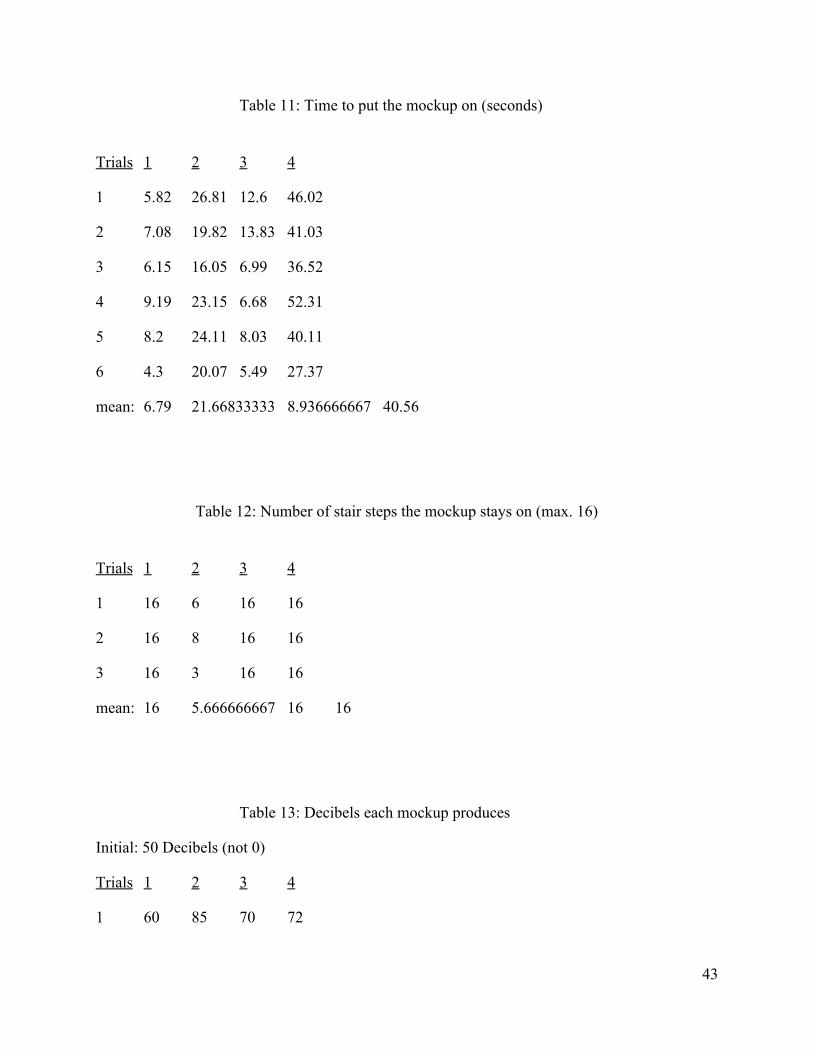
Table 11: Time to put the mockup on (seconds)
Trials 1 2 3 4
1 5.82 26.81 12.6 46.02
2 7.08 19.82 13.83 41.03
3 6.15 16.05 6.99 36.52
4 9.19 23.15 6.68 52.31
5 8.2 24.11 8.03 40.11
6 4.3 20.07 5.49 27.37
mean: 6.79 21.66833333 8.936666667 40.56
Table 12: Number of stair steps the mockup stays on (max. 16)
Trials 1 2 3 4
1 16 6 16 16
2 16 8 16 16
3 16 3 16 16
mean: 16 5.666666667 16 16
Table 13: Decibels each mockup produces
Initial: 50 Decibels (not 0)
Trials 1 2 3 4
1 60 85 70 72
43
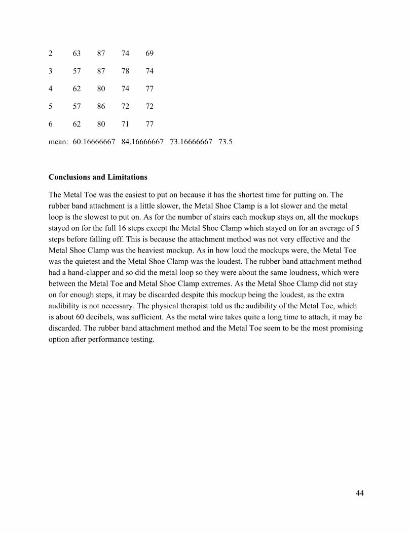
2 63 87 74 69
3 57 87 78 74
4 62 80 74 77
5 57 86 72 72
6 62 80 71 77
mean: 60.16666667 84.16666667 73.16666667 73.5
Conclusions and Limitations
The Metal Toe was the easiest to put on because it has the shortest time for putting on. The rubber band attachment is a little slower, the Metal Shoe Clamp is a lot slower and the metal loop is the slowest to put on. As for the number of stairs each mockup stays on, all the mockups stayed on for the full 16 steps except the Metal Shoe Clamp which stayed on for an average of 5 steps before falling off. This is because the attachment method was not very effective and the Metal Shoe Clamp was the heaviest mockup. As in how loud the mockups were, the Metal Toe was the quietest and the Metal Shoe Clamp was the loudest. The rubber band attachment method had a hand-clapper and so did the metal loop so they were about the same loudness, which were between the Metal Toe and Metal Shoe Clamp extremes. As the Metal Shoe Clamp did not stay on for enough steps, it may be discarded despite this mockup being the loudest, as the extra audibility is not necessary. The physical therapist told us the audibility of the Metal Toe, which is about 60 decibels, was sufficient. As the metal wire takes quite a long time to attach, it may be discarded. The rubber band attachment method and the Metal Toe seem to be the most promising option after performance testing.
44
APPENDIX H: INSTRUCTIONS FOR CONSTRUCTION
Includes materials for the Clipper Clapper and how to assemble them so that the device can be recreated. Introduction
These instructions will guide you through the process of creating a Clipper Clapper. There are six sections:
1. Creating the connecting frame 2. Painting the bulldog clip and castanet 3. Attaching the connecting frame to the bulldog clip with epoxy 4. Attaching the connecting frame to the castanet 5. Creating the loop of elastic 6. Attaching the loop of elastic
These instructions are intended for users of any level of background experience. However, experience with basic sewing stitches may be useful. It is important to note that the time for overall construction should fall under two hours, users should allot extra time for construction, ideally 24 hours, to allow the paint and epoxy to dry.
Materials List
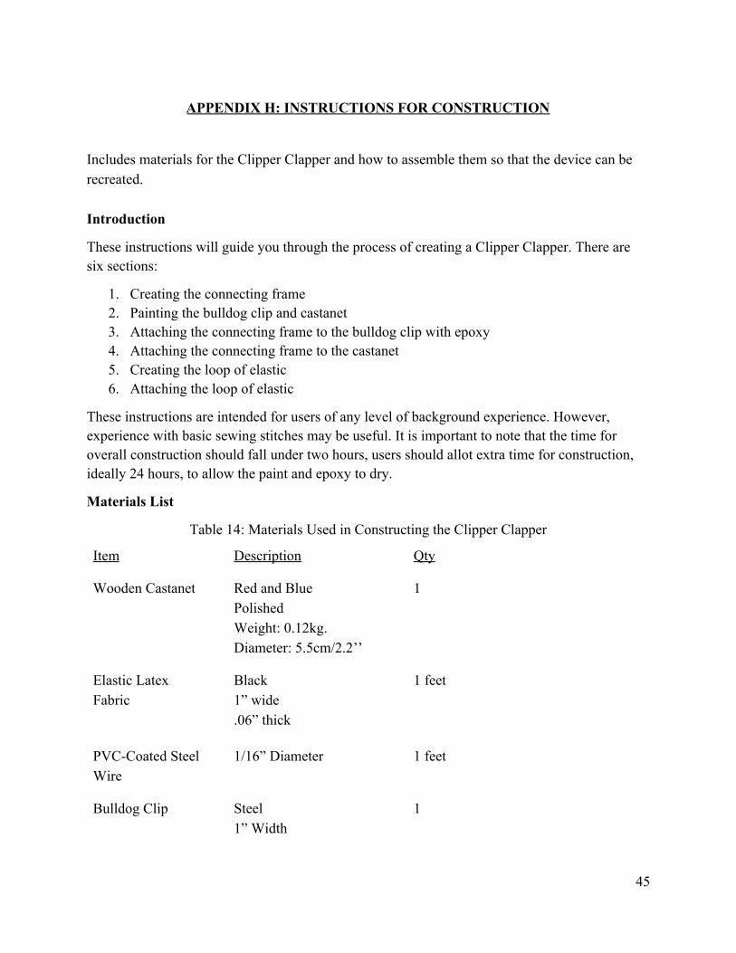
Table 14: Materials Used in Constructing the Clipper Clapper
Item Description Qty
Wooden Castanet Red and Blue Polished Weight: 0.12kg. Diameter: 5.5cm/2.2’’
1
Elastic Latex Fabric
Black 1” wide .06” thick
1 feet
PVC-Coated Steel Wire
1/16” Diameter 1 feet
Bulldog Clip Steel 1” Width
1
45
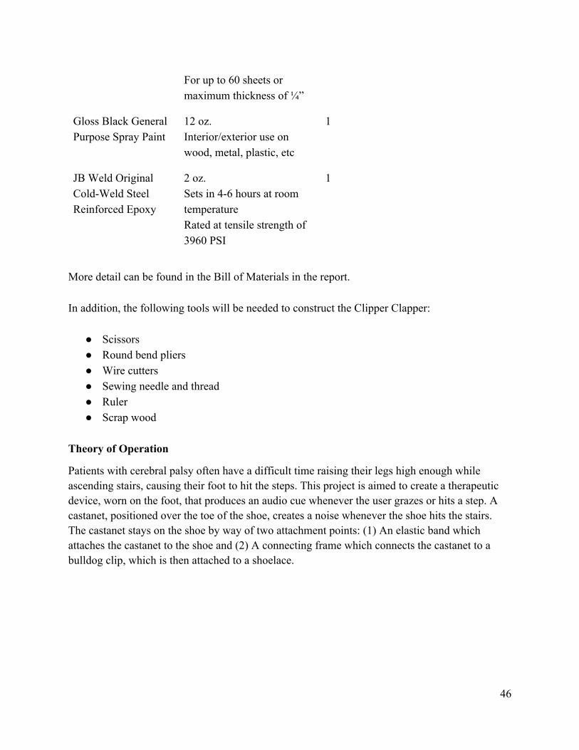
For up to 60 sheets or maximum thickness of ¼”
Gloss Black General Purpose Spray Paint
12 oz. Interior/exterior use on wood, metal, plastic, etc
1
JB Weld Original Cold-Weld Steel Reinforced Epoxy
2 oz. Sets in 4-6 hours at room temperature Rated at tensile strength of 3960 PSI
1
More detail can be found in the Bill of Materials in the report. In addition, the following tools will be needed to construct the Clipper Clapper:
● Scissors ● Round bend pliers ● Wire cutters ● Sewing needle and thread ● Ruler ● Scrap wood
Theory of Operation
Patients with cerebral palsy often have a difficult time raising their legs high enough while ascending stairs, causing their foot to hit the steps. This project is aimed to create a therapeutic device, worn on the foot, that produces an audio cue whenever the user grazes or hits a step. A castanet, positioned over the toe of the shoe, creates a noise whenever the shoe hits the stairs. The castanet stays on the shoe by way of two attachment points: (1) An elastic band which attaches the castanet to the shoe and (2) A connecting frame which connects the castanet to a bulldog clip, which is then attached to a shoelace.
46
Directions
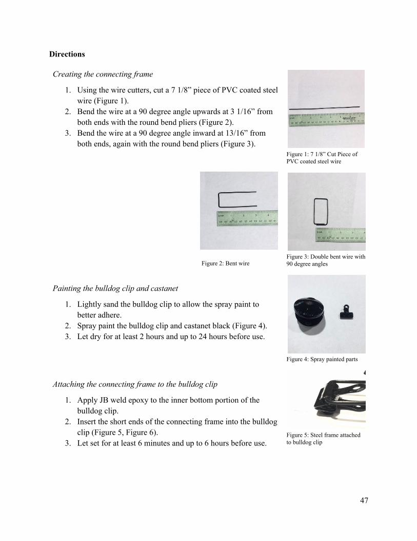
Creating the connecting frame
1. Using the wire cutters, cut a 7 1/8” piece of PVC coated steel wire (Figure 1).
2. Bend the wire at a 90 degree angle upwards at 3 1/16” from both ends with the round bend pliers (Figure 2).
3. Bend the wire at a 90 degree angle inward at 13/16” from both ends, again with the round bend pliers (Figure 3).
Figure 2: Bent wire
Painting the bulldog clip and castanet
1. Lightly sand the bulldog clip to allow the spray paint to better adhere.
2. Spray paint the bulldog clip and castanet black (Figure 4). 3. Let dry for at least 2 hours and up to 24 hours before use.
Attaching the connecting frame to the bulldog clip
1. Apply JB weld epoxy to the inner bottom portion of the bulldog clip.
2. Insert the short ends of the connecting frame into the bulldog clip (Figure 5, Figure 6).
3. Let set for at least 6 minutes and up to 6 hours before use.
Figure 1: 7 1/8” Cut Piece of PVC coated steel wire
Figure 3: Double bent wire with 90 degree angles
Figure 4: Spray painted parts
Figure 5: Steel frame attached to bulldog clip
47
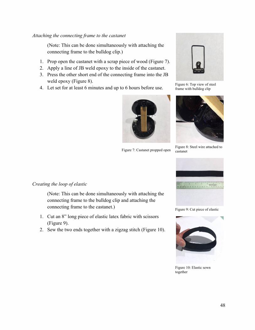
Attaching the connecting frame to the castanet
(Note: This can be done simultaneously with attaching the connecting frame to the bulldog clip.)
1. Prop open the castanet with a scrap piece of wood (Figure 7). 2. Apply a line of JB weld epoxy to the inside of the castanet. 3. Press the other short end of the connecting frame into the JB
weld epoxy (Figure 8). 4. Let set for at least 6 minutes and up to 6 hours before use.
Figure 7: Castanet propped open
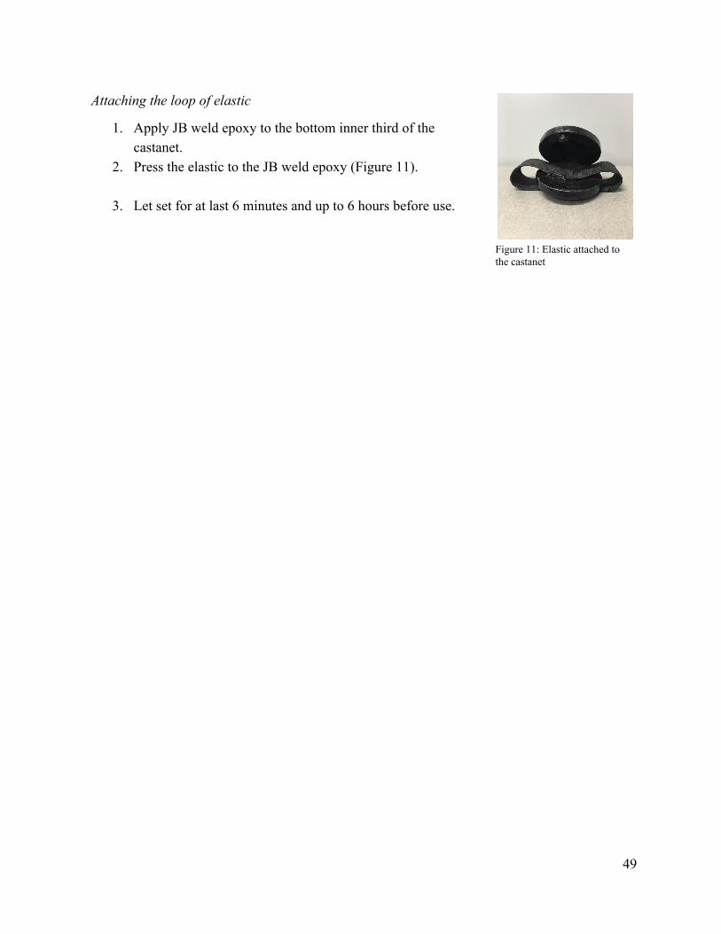
Creating the loop of elastic
(Note: This can be done simultaneously with attaching the connecting frame to the bulldog clip and attaching the connecting frame to the castanet.)
1. Cut an 8” long piece of elastic latex fabric with scissors (Figure 9).
2. Sew the two ends together with a zigzag stitch (Figure 10).
Figure 6: Top view of steel frame with bulldog clip
Figure 8: Steel wire attached to castanet
Figure 9: Cut piece of elastic
Figure 10: Elastic sewn together
48
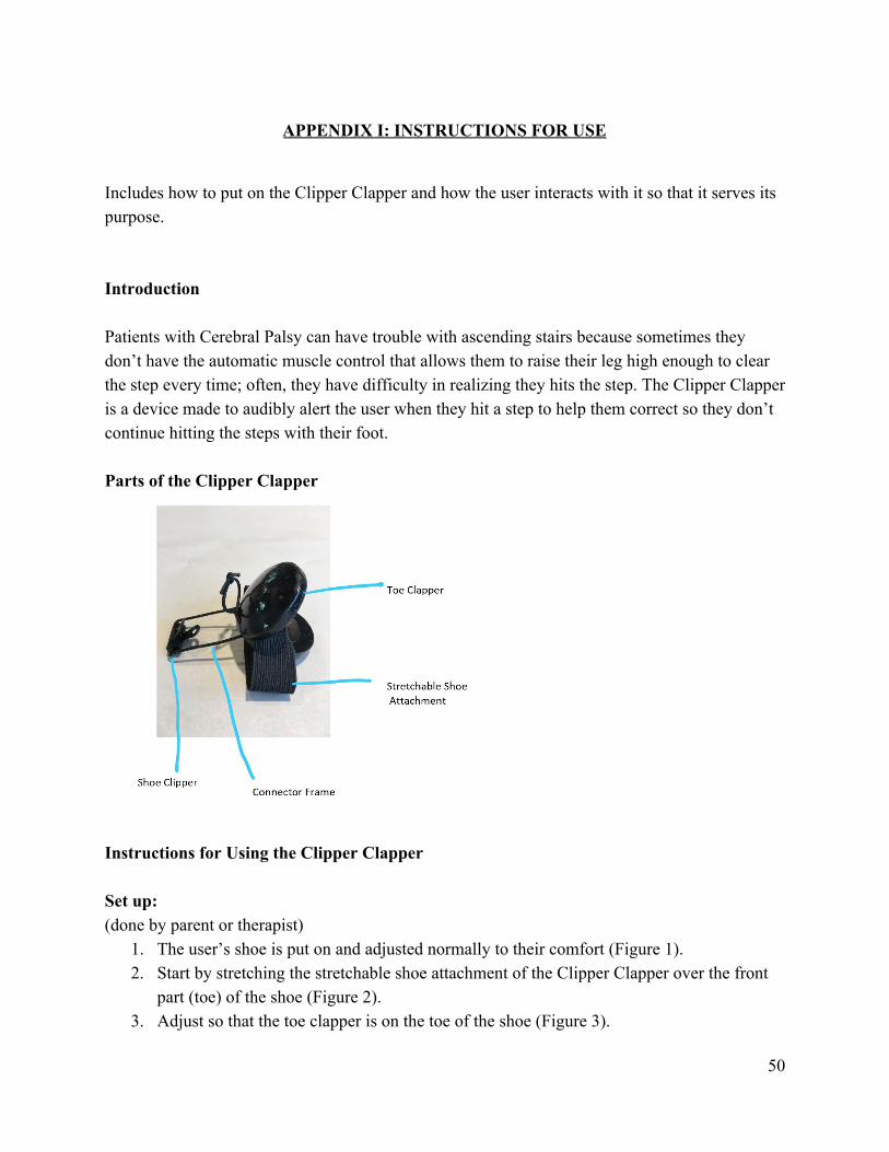
Attaching the loop of elastic
1. Apply JB weld epoxy to the bottom inner third of the castanet.
2. Press the elastic to the JB weld epoxy (Figure 11).
3. Let set for at last 6 minutes and up to 6 hours before use.
Figure 11: Elastic attached to the castanet
49
APPENDIX I: INSTRUCTIONS FOR USE
Includes how to put on the Clipper Clapper and how the user interacts with it so that it serves its purpose.
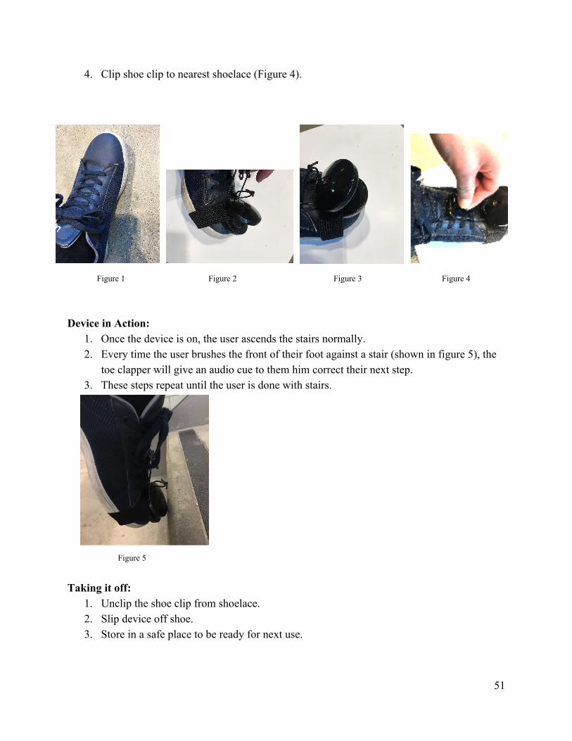
Introduction Patients with Cerebral Palsy can have trouble with ascending stairs because sometimes they don’t have the automatic muscle control that allows them to raise their leg high enough to clear the step every time; often, they have difficulty in realizing they hits the step. The Clipper Clapper is a device made to audibly alert the user when they hit a step to help them correct so they don’t continue hitting the steps with their foot. Parts of the Clipper Clapper
Instructions for Using the Clipper Clapper Set up: (done by parent or therapist)
1. The user’s shoe is put on and adjusted normally to their comfort (Figure 1). 2. Start by stretching the stretchable shoe attachment of the Clipper Clapper over the front
part (toe) of the shoe (Figure 2). 3. Adjust so that the toe clapper is on the toe of the shoe (Figure 3).
50
4. Clip shoe clip to nearest shoelace (Figure 4).
Figure 1 Figure 2 Figure 3 Figure 4
Device in Action:
1. Once the device is on, the user ascends the stairs normally. 2. Every time the user brushes the front of their foot against a stair (shown in figure 5), the
toe clapper will give an audio cue to them him correct their next step. 3. These steps repeat until the user is done with stairs.
Figure 5
Taking it off:
1. Unclip the shoe clip from shoelace. 2. Slip device off shoe. 3. Store in a safe place to be ready for next use.
51