Embed Size (px)
Citation preview

AN41908A Lens DriverAN41919A DC Iris Driver
NEW! Special Function Motor Drivers

Panasonic Special Function Motor Drivers For Panasonic Special Function Motor Drivers For Network and Security CamerasNetwork and Security Cameras
1ch Iris controller (Iris servo for dumping coil 1chAN41919ADC Iris Driver
for Box type
UnderMP
QFN44(6mm×6mm)
5ch motor drive controller(Zoom 2ch + Focus 2ch
+ Iris servo for hall sensor 1ch)AN41908ALens Driver
for Dome type
StatusPackage(Chip size)FunctionType
Dome Type Cameras(Iris Servo for Hall Sensor)
Box Type Camera(Iris Servo for Dumping Coil)

Panasonic AN41908ALens Driver for
Dome Type Camera((Iris Servo for Hall Sensor ))

Block Diagram of Network Camera Block Diagram of Network Camera (Hall Sensor)(Hall Sensor)
Image sensor(Including Analog Front End)
Motor2ch
Motor1ch
Motor2ch
Motor1ch
Motor1ch
Pan/Tilt Driver IC
MicroComputer
NetworkRecorder
Block diagram
Zoom/Focus Controller
Iris Controller
Single chip solutionLens Driver AN41908A
Single chip solutionLens Driver AN41908A
IrisZoomFocus

Position SensingElement
(Hall sensor)
MicroComputer
MIris
Zoom
Focus
CSCSKSIN
CS: Chip SelectCSK: Serial ClockSIN: Serial Data Input
Serial
I/F
Micro Step Control circuit
PWMDriver
IrisAnalog circuit
PWMDriver
Iris Digital circuit
(Digital PID)
PID: Proportional Integral Derivative
MMPWM
Driver
Micro Step Control circuit
Panasonic AN41908A Block DiagramPanasonic AN41908A Block DiagramTo Integrate Iris Control Function on Zoom & Focus DriverTo Integrate Iris Control Function on Zoom & Focus Driver

Panasonic AN41908A Single Chip AdvantagesPanasonic AN41908A Single Chip Advantages
PCB Space Reduction
Reduced Design-In Time
Low Acoustic Noise
Low Power Consumption

Zoom Focus
MIris
Hall
Senso
r
M MTotal Area = 381mm2
SOP24158.6mm2
SOP24158.6mm2
Company A
Total Area = 36mm2
(About 80-90% reduction!!)
AN41908AAN41908A
Total Area = 162mm2
Zoom Focus
MIris
Hall
Sensor
M MSSOP3297.8mm2 7878%%
ReductionReductionTSSOP14
32mm2TSSOP14
32mm2
TSSOP1432mm2
TSSOP1432mm2
M
Zoom Focus
IrisM M
HallSens
or
Hall Amp
Hall Bias
Hall Bias
Error AmpP I D M
Iris
8 OP Amps and external parts are needed for Iris function…
90.590.5%%ReductionReduction
1Chip LSI of Zoom,Focus and Iris function
- Small Camera design- PCB cost reduction
Company B
PCB PCB SpaceSpace RReductioneduction
HallSensor
AN41908A
Advantage for

MIris
Hall
Senso
r
SOP24SOP24
TSSOP14TSSOP14
Resistance/Capacitance
AN41908AAN41908A
MIris
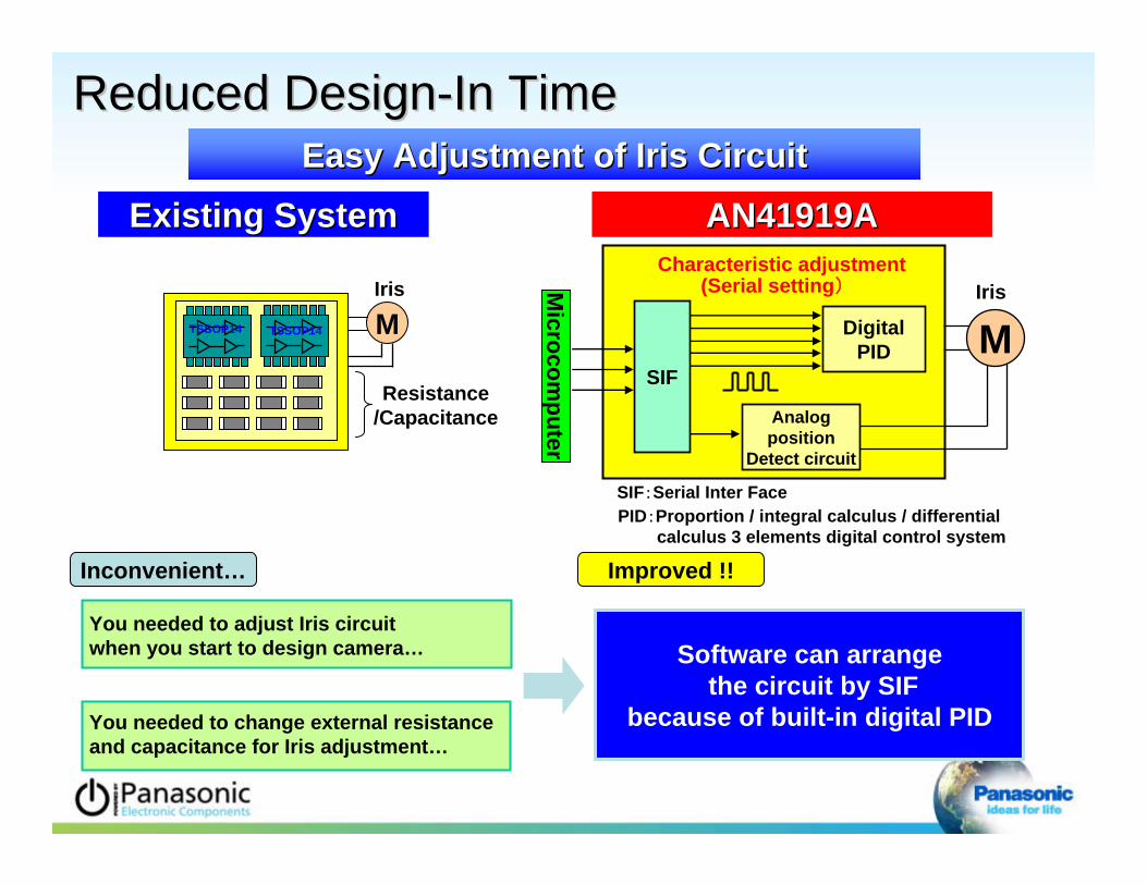
DigitalPID
Characteristic adjustment
SIF:Serial Inter FacePID:Proportion / integral calculus / differential
calculus 3 elements digital control system
HallSens
or
Analogposition
Detect circuit
ExistingExisting systemsystem
Microcom
puter
(Serial setting)
SIF
ReducReduced Designed Design--In TimeIn Time
You needed to adjust Iris circuitwhen you start to design camera…
You needed to change external resistance and capacitance for Iris adjustment…
Inconvenient… Improved !!
Easy Adjustment of Iris CircuitEasy Adjustment of Iris Circuit
Software can arrangethe circuit by SIF
because of built-in digital PID

Ideal motor current waveform
Back electromotive force unbalance
Phase gap
Motor tolerance
* Equal amplitude * Phase difference 90deg
Amplitude correction circuit
Phase correction circuit
90 °
Unbalance
Gap
Noi
se L
evel
(dB)
No correction
-15
-10
-5
0
5
10
15
20
25
30
35
2.50Hz
32.50Hz
62.50Hz
92.50Hz
122.50Hz
152.50Hz
182.50Hz
212.50Hz
242.50Hz
272.50Hz
302.50Hz
332.50Hz
362.50Hz
392.50Hz
422.50Hz
452.50Hz
482.50Hz
512.50Hz
542.50Hz
572.50Hz
602.50Hz
632.50Hz
662.50Hz
692.50Hz
722.50Hz
752.50Hz
782.50Hz
812.50Hz
842.50Hz
872.50Hz
902.50Hz
932.50Hz
962.50Hz
992.50Hz
-15
-10
-5
0
5
10
15
20
25
30
35
2.50Hz
35.00Hz
67.50Hz
100.00Hz
132.50Hz
165.00Hz
197.50Hz
230.00Hz
262.50Hz
295.00Hz
327.50Hz
360.00Hz
392.50Hz
425.00Hz
457.50Hz
490.00Hz
522.50Hz
555.00Hz
587.50Hz
620.00Hz
652.50Hz
685.00Hz
717.50Hz
750.00Hz
782.50Hz
815.00Hz
847.50Hz
880.00Hz
912.50Hz
945.00Hz
977.50Hz
Frequency (Hz)Frequency (Hz)
Noi
se L
evel
(dB)
Correction
Low Low NNoise oise MMicro icro SStep tep DDrive for Zoom and Focusrive for Zoom and Focus
-10dB !!
Less Acoustic Noise by Motor Tolerance Correction FunctionLess Acoustic Noise by Motor Tolerance Correction Function

Low Power ConsumptionLow Power Consumption
Hall sensor
Iris
MPWMDrive
Digital control part
+/-
Analog position detecting circuit
Position signal from
microcomputer
50% power reduction 50% power reduction by PWM driving system by PWM driving system !!!!(C(Compared with Linear driving system)ompared with Linear driving system)
PID
Iris analog circuitADC
PWM noise cutby digital filter part Iris digital Circuit
low pass low pass
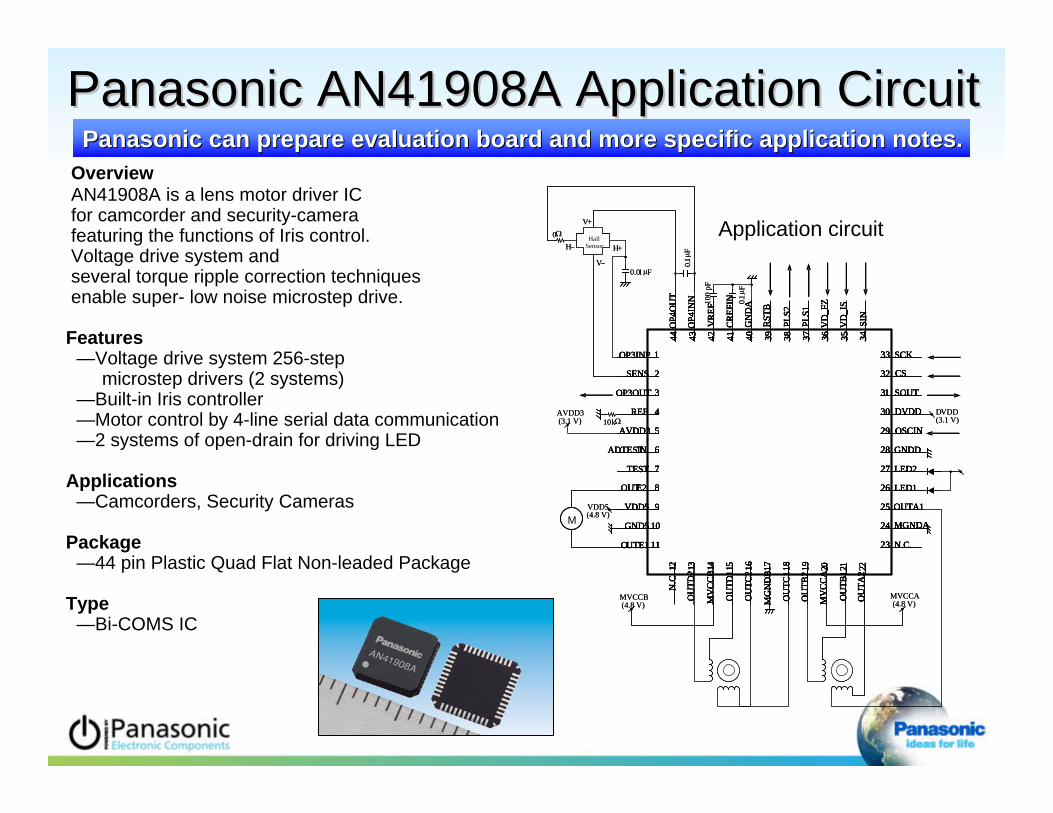
OverviewAN41908A is a lens motor driver IC for camcorder and security-camera featuring the functions of Iris control. Voltage drive system and several torque ripple correction techniques enable super- low noise microstep drive.
Features—Voltage drive system 256-step
microstep drivers (2 systems)—Built-in Iris controller —Motor control by 4-line serial data communication—2 systems of open-drain for driving LED
Applications—Camcorders, Security Cameras
Package—44 pin Plastic Quad Flat Non-leaded Package
Type—Bi-COMS IC
Application circuitV+
V–
1
2
3
4
5
6
7
8
9
10
11
OP3INP
SENS
OP3OUT
REF
AVDD3
ADTESTIN
TEST
OUTE2
VDD5
GND5
OUTE1
12 13 14 15 16 17 18 19 20 21 22
N.C
.
OU
TD2
OU
TD1
MG
ND
B
OU
TC2
OU
TC1
MV
CC
B
OU
TB2
OU
TB1
OU
TA2
MV
CC
A
44 43 42 41 40 39 38 37 36 35 34
PLS1
SIN
VD
_FZ
VD
_IS
RST
B
OP4
OU
T
OP4
INN
VR
EF
GN
DA
CR
EFIN
PLS2
23
33
32
31
30
29
28
27
26
25
24 MGNDA
OUTA1
N.C.
SCK
SOUT
CS
GNDD
LED2
LED1
OSCIN
DVDD
HallSensorH– H+
0
0.1 F
100
pF
0.1 F
10kAVDD3(3.1 V)
MVDD5(4.8 V)
MVCCB(4.8 V)
MVCCA(4.8 V)
DVDD(3.1 V)
0.01 F
V+
V–
1
2
3
4
5
6
7
8
9
10
11
OP3INP
SENS
OP3OUT
REF
AVDD3
ADTESTIN
TEST
OUTE2
VDD5
GND5
OUTE1
12 13 14 15 16 17 18 19 20 21 22
N.C
.
OU
TD2
OU
TD1
MG
ND
B
OU
TC2
OU
TC1
MV
CC
B
OU
TB2
OU
TB1
OU
TA2
MV
CC
A
44 43 42 41 40 39 38 37 36 35 34
PLS1
SIN
VD
_FZ
VD
_IS
RST
B
OP4
OU
T
OP4
INN
VR
EF
GN
DA
CR
EFIN
PLS2
23
33
32
31
30
29
28
27
26
25
24 MGNDA
OUTA1
N.C.
SCK
SOUT
CS
GNDD
LED2
LED1
OSCIN
DVDD
1
2
3
4
5
6
7
8
9
10
11
OP3INP
SENS
OP3OUT
REF
AVDD3
ADTESTIN
TEST
OUTE2
VDD5
GND5
OUTE1
1
2
3
4
5
6
7
8
9
10
11
OP3INP
SENS
OP3OUT
REF
AVDD3
ADTESTIN
TEST
OUTE2
VDD5
GND5
OUTE1
12 13 14 15 16 17 18 19 20 21 22
N.C
.
OU
TD2
OU
TD1
MG
ND
B
OU
TC2
OU
TC1
MV
CC
B
OU
TB2
OU
TB1
OU
TA2
MV
CC
A
12 13 14 15 16 17 18 19 20 21 22
N.C
.
OU
TD2
OU
TD1
MG
ND
B
OU
TC2
OU
TC1
MV
CC
B
OU
TB2
OU
TB1
OU
TA2
MV
CC
A
44 43 42 41 40 39 38 37 36 35 34
PLS1
SIN
VD
_FZ
VD
_IS
RST
B
OP4
OU
T
OP4
INN
VR
EF
GN
DA
CR
EFIN
PLS2
44 43 42 41 40 39 38 37 36 35 34
PLS1
SIN
VD
_FZ
VD
_IS
RST
B
OP4
OU
T
OP4
INN
VR
EF
GN
DA
CR
EFIN
PLS2
23
33
32
31
30
29
28
27
26
25
24 MGNDA
OUTA1
N.C.
SCK
SOUT
CS
GNDD
LED2
LED1
OSCIN
DVDD
23
33
32
31
30
29
28
27
26
25
24 MGNDA
OUTA1
N.C.
SCK
SOUT
CS
GNDD
LED2
LED1
OSCIN
DVDD
HallSensorH– H+
0
0.1 F
100
pF
0.1 F
10kAVDD3(3.1 V)
MVDD5(4.8 V)
MVCCB(4.8 V)
MVCCA(4.8 V)
DVDD(3.1 V)
0.01 F
Panasonic AN41908A Application CircuitPanasonic AN41908A Application CircuitPanasonic can prepare evaluation board and more specific applicaPanasonic can prepare evaluation board and more specific application notes.tion notes.

Evaluation BoardEvaluation Board

Panasonic AN41919ADC Iris Driver for
Box Type Camera(Iris Servo for Dumping Coil)
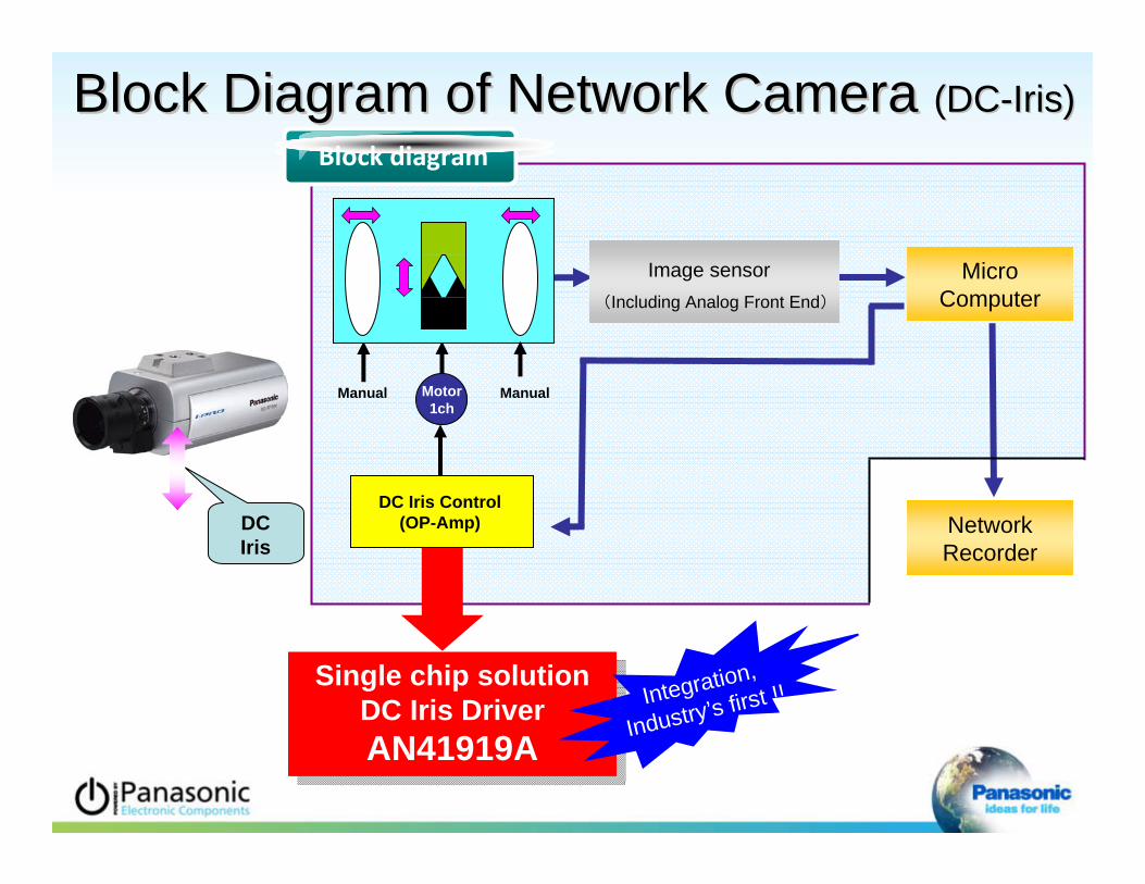
Block Diagram of Network Camera Block Diagram of Network Camera (DC(DC--Iris)Iris)
Image sensor(Including Analog Front End)
Motor1ch
MicroComputer
NetworkRecorder
Block diagram
DC Iris Control(OP-Amp)
Single chip solutionDC Iris Driver AN41919A
Single chip solutionDC Iris Driver AN41919A
Integration,
Industry’s first !!
DCIris
ManualManual

Panasonic AN41919A Block DiagramPanasonic AN41919A Block Diagram
AN41919A
MicroComputer M
CS
SCK
SIN
CS: Chip SelectSCK: Serial ClockSIN: Serial Data Input
SerialI/F PWM
Driver
Parameter setting
IrisAnalogcircuit
IrisDigitalCircuit
(Digital PID)
Luminance target signal Damping Coil
Signal
Target Signal
Single Chip Solution of DC Iris Function
Contributes to SetsContributes to Sets’’ Miniature Design.Miniature Design.

Panasonic AN41919A AdvantagesPanasonic AN41919A Advantages
Reduced Design-In Time
Low Power Consumption
SIF:Serial Inter Face
ExistingExisting SystemSystem
PID:Proportion / integral calculus / differentialcalculus 3 elements digital control system
ReducReduced Designed Design--In TimeIn Time
AN41919AAN41919A
Iris
DigitalPID
Characteristic adjustment
Microcom
puter
(Serial setting)
SIFM
Analogposition
Detect circuit
Easy Adjustment of Iris CircuitEasy Adjustment of Iris Circuit
You needed to adjust Iris circuitwhen you start to design camera…
You needed to change external resistance and capacitance for Iris adjustment…
Inconvenient… Improved !!
Software can arrangethe circuit by SIF
because of built-in digital PID
MIris
TSSOP14TSSOP14
Resistance/Capacitance

IrisDigital control part
+/-
Analog position detecting circuit
PID
Iris analog circuitADC
Iris digital circuit
low pass low pass
M
Luminance target Signal
PWMDriver
Luminance signal from
microcomputer
Low Power ConsumptionLow Power Consumption
50% Power Reduction 50% Power Reduction by PWM Driving Systemby PWM Driving System(C(Compared with Linear driving system)ompared with Linear driving system)
PWM noise cutby digital filter part

DR
V_O
UT1
DR
V_O
UT2
1
2
3
4
5
6
7
8
9
10
11
12 13 14 15 16 17 18 19 20 21 22
44 43 42 41 40 39 38 37 36 35 34
23
33
32
31
30
29
28
27
26
25
24
100 pFAVDD3(3.1 V)
VDD5(4.8 V)
DVDD(3.1 V)
0.1 FVREF
CREF
AVDD3
ADCIN
N.C.
N.C.
VD
D5
N.C
.
SOU
T
CS
SIN
N.C
.
SCK
OSCIN
OSCOUT
N.C.
N.C.
TEST
N.C.
MONI_2
MONI_1
DVDD
VD_IN
GNDD
TESTOUT
AMPINP
AMPINN
AMPOUT
N.C.
N.C
.
GN
D5
N.C
.
N.C
.
RST
ENA
BLE
N.C
.
AM
P2O
UT
PWM
_IN
N.C
.
GN
DA
AM
P2IN
P
N.C
.
Drive Coil
Damping Coil
CD
S si
gnal
PWM
sign
al
VD signal
OverviewAN41919A is a iris control LSI
for IP-camera and security-camera.
Features—Built-in Iris controller—Iris control by 4-line
serial data communication
Applications—IP-camera, Security-camera
Package—44 pin Plastic Quad Flat Non-leaded Package
Type—Bi-COMS IC
Application Circuit
Panasonic AN41919A Application CircuitPanasonic AN41919A Application CircuitPanasonic can prepare evaluation board and more specific applicaPanasonic can prepare evaluation board and more specific application notes.tion notes.

Evaluation BoardEvaluation Board

AN41908A Lens DriverAN41919A DC Iris Driver
NEW! Special Function Motor Drivers