Embed Size (px)
Citation preview

Zhu, X., Doufexi, A., & Koçak, T. (2011). A performance evaluation of 60GHz MIMO systems for IEEE 802.11ad WPANs. In IEEE 22ndInternational Symposium on Personal Indoor and Mobile RadioCommunications (PIMRC), 2011 (pp. 950 - 954). Institute of Electrical andElectronics Engineers (IEEE). https://doi.org/10.1109/PIMRC.2011.6140109
Peer reviewed version
Link to published version (if available):10.1109/PIMRC.2011.6140109
Link to publication record in Explore Bristol ResearchPDF-document
University of Bristol - Explore Bristol ResearchGeneral rights
This document is made available in accordance with publisher policies. Please cite only the publishedversion using the reference above. Full terms of use are available:http://www.bristol.ac.uk/pure/about/ebr-terms

A Performance Evaluation of 60 GHz MIMO Systems for IEEE 802.11ad WPANs
Xiaoyi Zhu*, Angela Doufexi*, and Taskin Kocak†
*Department of Electrical and Electronic Engineering
University of Bristol, Bristol, United Kingdom {X.Zhu, A.Doufexi}@bristol.ac.uk
†Department of Computer Engineering
Bahcesehir University, Istanbul, Turkey [email protected]
Abstract— The IEEE 802.11ad task group has published its first draft to cope with the characteristics in 60 GHz millimeter-wave (mmWave) wireless communications. In this paper, three different 2×2 multiple-input multiple-output (MIMO) techniques are considered to enhance the performance of 60 GHz wireless personal networks (WPANs). Packet Error Rate (PER) and link throughput performance are simulated under different channel conditions. In addition, the system throughput over operation range is presented in the paper. Results show that significant enhancements in both coverage and capacity can be achieved by employing space-time block codes (STBC), spatial multiplexing (SM) and three different configurations of beamforming.
Keywords- WPAN; 60 GHz; IEEE 802.11ad; OFDM; MIMO
I. INTRODUCTION
The wireless local and personal communications have been experienced increasing interest with the tremendous growth in multimedia applications in recent years. The successful 2.4/5 GHz wireless systems have already increased the data rate to 600 Mbps with multiple-input multiple-output (MIMO) techniques. However, with the development of CMOS design and the availability of the 60 GHz unlicensed millimeter-wave (mmWave) band, it is possible to deliver even higher quality multimedia and data services. To accommodate the characteristics of the mmWave, the IEEE 802.11ad task group was formed to amend the existing standard on both physical (PHY) and medium access control (MAC) layers within the 57-66 GHz band [1]. The orthogonal frequency division multiplexing (OFDM) and single carrier (SC) transmission are specified in the standard. The SC mode is used for control information and low complexity transceivers, while the OFDM mode is designed for delivering high performance applications.
MIMO techniques have been studied extensively in the last decade, and in general, they can be classified into three types. One of the techniques is space-time block coding (STBC), which aims to improve the power efficiency by maximizing spatial diversity. The advantage of STBC is it enables the use of linear decoding at the receiver, and with OFDM, it can be easily implemented. Another technique is spatial multiplexing (SM), which increases the spectral efficiency by transmitting parallel data streams without the need of extra bandwidth. A higher throughput can be achieved by SM and the process does not introduce any coding redundancy. Beamforming is the third type of multiple antenna technique, and the objective is to utilize the directivity of the signal transmission and reception.
Compared to STBC and SM, beamforming only needs to utilize one spatial channel among a multiple of parallel channels. In OFDM system, beamforming can be carried out by three generic types, namely, subcarrier-wise beamforming, symbol-wise beamforming, and hybrid beamforming [2]. The first type performs beamforming in the frequency domain and the second type carries out in the time domain. The hybrid beamforming, which employs symbol-wise beamforming at the transmitter and subcarrier-wise beamforming at the receiver, compromises the complexity and performance.
The rest of this paper is organized as follows. The PHY and channel models of IEEE 802.11ad WPANs are presented in Section II. The OFDM based MIMO models are described in Section III. In Section IV, the packet error rate (PER) performance of STBC, SM and three different beamforming schemes are simulated using our IEEE 802.11ad PHY simulator. The link throughput and operation range results are also investigated. Section V concludes the paper.
II. WPANS PHY AND CHANNEL MODELS
In IEEE 802.11ad, the large spectrum around 60 GHz is equally divided into four channels. In this study, an OFDM system with 2.16 GHz bandwidth is considered to combat frequency selective fading. The OFDM is implemented by means of an inverse FFT, and a total number of 512 subcarriers are transmitted in parallel in the form of one OFDM symbol. In order to eliminate inter symbol interference (ISI), a length of 128 cyclic prefix is added to each symbol. The key parameters used for the simulation of the MIMO-OFDM PHY in this paper are shown in Table I.
TABLE I. PARAMETERS FOR OFDM SYSTEMS IN IEEE 802.11AD
Parameter Value
Sampling frequency (MHz) 2640
Number of subcarriers 512
Number of data subcarriers 336
Number of pilot subcarriers 16
Subcarrier frequency spacing (MHz) 5.156
Sample duration (ns) 0.38
IFFT and FFT period (ns) 194
OFDM symbol duration (ns) 242
Let be the received decision baseband signal for the mth subcarrier, which can be expressed as
, 1, … (1)
where is the transmitted data symbol, is the Gaussian noise vector with zero mean and variance σ2, N is number of subcarriers, and represents the frequency response of the equivalent channel matrix for the mth subcarrier.
Based on the clustering phenomenon in both the temporal and spatial domains, a statistic channel model from a combination of measurements and ray-tracing was proposed for the 60 GHz WPANs [3]. We consider a 1-D uniform linear array consisting of Mt and Mr antenna elements at the transmitter and the receiver respectively. The antenna element spacing is half wavelength λ. The channels are generated with isotropic radiators in both line-of-sight (LOS) and non-line-of sight (NLOS) cases. To evaluate the performance of STBC and SM in IEEE 802.11ad, different degrees of channel correlation are considered. We assume the average channel matrix value across all channel realizations are 0.1 (low), 0.5 (medium) and 0.9 (high) respectively. It is assumed that the communication channel remains constant during an OFDM data packet transmission. The 60 GHz average path loss (PL) model considering shadow fading can be modeled as [3]:
dB 20 log 10 log (2) where for LOS scenario A = 32.5 dB, n = 2.0, and for NLOS scenario A = 51.5 dB, n = 0.6, f is the carrier frequency in GHz, and D is the distance between the transceivers in meter.
III. OFDM BASED MIMO MODEL
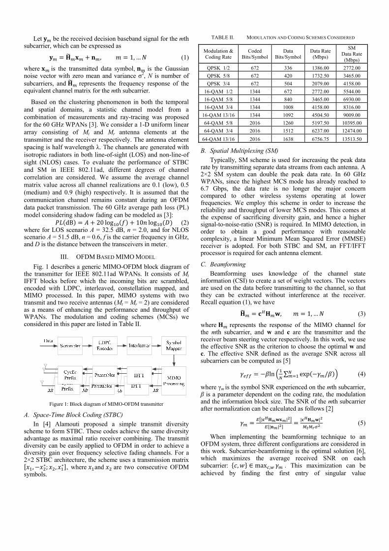
Fig. 1 describes a generic MIMO-OFDM block diagram of the transmitter for IEEE 802.11ad WPANs. It consists of Mt IFFT blocks before which the incoming bits are scrambled, encoded with LDPC, interleaved, constellation mapped, and MIMO processed. In this paper, MIMO systems with two transmit and two receive antennas (Mt = Mr = 2) are considered as a means of enhancing the performance and throughput of WPANs. The modulation and coding schemes (MCSs) we considered in this paper are listed in Table II.
Figure 1: Block diagram of MIMO-OFDM transmitter
A. Space-Time Block Coding (STBC)
In [4] Alamouti proposed a simple transmit diversity scheme to form STBC. These codes achieve the same diversity advantage as maximal ratio receiver combining. The transmit diversity can be easily applied to OFDM in order to achieve a diversity gain over frequency selective fading channels. For a 2×2 STBC architecture, the scheme uses a transmission matrix
, ∗; , ∗ , where and are two consecutive OFDM symbols.
TABLE II. MODULATION AND CODING SCHEMES CONSIDERED
Modulation & Coding Rate
Coded Bits/Symbol
Data Bits/Symbol
Data Rate (Mbps)
SM Data Rate
(Mbps)
QPSK 1/2 672 336 1386.00 2772.00
QPSK 5/8 672 420 1732.50 3465.00
QPSK 3/4 672 504 2079.00 4158.00
16-QAM 1/2 1344 672 2772.00 5544.00
16-QAM 5/8 1344 840 3465.00 6930.00
16-QAM 3/4 1344 1008 4158.00 8316.00
16-QAM 13/16 1344 1092 4504.50 9009.00
64-QAM 5/8 2016 1260 5197.50 10395.00
64-QAM 3/4 2016 1512 6237.00 12474.00
64-QAM 13/16 2016 1638 6756.75 13513.50
B. Spatial Multiplexing (SM)
Typically, SM scheme is used for increasing the peak data rate by transmitting separate data streams from each antenna. A 2×2 SM system can double the peak data rate. In 60 GHz WPANs, since the highest MCS mode has already reached to 6.7 Gbps, the data rate is no longer the major concern compared to other wireless systems operating at lower frequencies. We employ this scheme in order to increase the reliability and throughput of lower MCS modes. This comes at the expense of sacrificing diversity gain, and hence a higher signal-to-noise-ratio (SNR) is required. In MIMO detection, in order to obtain a good performance with reasonable complexity, a linear Minimum Mean Squared Error (MMSE) receiver is adopted. For both STBC and SM, an FFT/IFFT processor is required for each antenna element.
C. Beamforming
Beamforming uses knowledge of the channel state information (CSI) to create a set of weight vectors. The vectors are used on the data before transmitting to the channel, so that they can be extracted without interference at the receiver. Recall equation (1), we have
, 1, … (3)
where represents the response of the MIMO channel for the mth subcarrier, and w and c are the transmitter and the receiver beam steering vector respectively. In this work, we use the effective SNR as the criterion to choose the optimal w and c. The effective SNR defined as the average SNR across all subcarriers can be computed as [5]
ln ∑ exp / (4)
where γm is the symbol SNR experienced on the mth subcarrier, β is a parameter dependent on the coding rate, the modulation and the information block size. The SNR of the mth subcarrier after normalization can be calculated as follows [2]
| |
| |
| | (5)
When implementing the beamforming technique to an OFDM system, three different configurations are considered in this work. Subcarrier-beamforming is the optimal solution [6], which maximizes the average received SNR on each subcarrier: , ∈ max , . This maximization can be achieved by finding the first entry of singular value

deco2, sprocmustcomp
DbeamThe the t[6] rsubcsubcintroeffecpropsymbminisubcstruc
Hintendefinsystewithampantenprobbest for htransmax
,
A. L
Isimusysteprev
Fversuthat a cerSNRtrans
omposition (SVsubcarrier-wis
cessor per antt be sent bputation need
Figure 2: Bl
Despite the sumforming is ncomplexity ca
time domain arequires only ocarrier appliecarrier-wise beoduce a perfoctive SNR foposed a hybrbol-wise beamimize the comcarrier-wise becture is shown
However, in nsive, and in oned beam codems [7]. As d
h four orthoglitude adjustmnna elements,
blem for symbpair of code
hybrid beamfosmitter vectx ∈ , ancan be obta
Link Level Sim
In this sectionulator to preseem (SISO) a
vious section. T
Fig. 5 presentsus the averagin general higrtain PER. The
R is below 1smission targe
VD) of the chse beamformtenna. In addiback to the a SVD proces
lock diagram of s
uperior performnot employed ban be reduced
as shown in Figone FFT procs the same eamforming,
formance lossor overall subrid beamformmforming is
mplexity, and eamforming ton in Fig. 4.
practice, obtaorder to avoid
debook is useddefined in [8],gonal shifts ment. It is dete, and the desirbol-wise beam
ebook (CB): orming, we otor w fromnd the optimaained from w b
IV. NUMER
mulation Resul
, we use our Ient the PER and MIMO sThe packet siz
s the SISO PEge SNR for thgher data rate re system cann
1 dB in suchet of 1%, the
hannel matrix.ming requires
ition, estimatetransmitter,
ssor per subca
subcarrier-wise b
mance, in prabecause of the
d by performing. 3. Symbol-wessor at each weight vect
symbol-wise s because onbcarriers can
ming techniquemployed at the receiver i
o optimize the
aining CSI id these calculad for rapid pro, the beam coper antenna ermined by bred number ofmforming bec, ∈ max
nly need to cm the codal receiver beaby using Schw
RICAL RESULT
lts
IEEE 802.11aperformance
schemes we ze is 1 KB in a
ER performanche LOS channrequires highenot provide anyh a scenario.e system will
. As shown ins one FFT/Ied channel m
and the warrier.
eamforming
actice, this type high compleng beamforminwise beamformterminal, and or. Comparebeamforming
nly the maximbe satisfied
ue, in whichthe transmitte
is configured e performance.
s computationations, a set ofcessing in 60
odebook is creelement wit
oth the numbf beams. Thencomes to find, ∈ . W
choose the optdebook: ,am steering v
wartz’s inequal
TS
ad PHY MATof single antdescribed in
all scenarios.
ce of all the mnel. It can be er SNR to mainy service whe. Given the be at the hig
n Fig. IFFT
matrix weight
pe of exity. ng in ming each
ed to g will mum
d. [2] h the ter to
with . The
onally f pre-GHz eated thout
ber of n, the d the While timal
∈vector lity.
TLAB tenna n the
modes seen
intain en the
PER ghest
MCshowthe ssize
Fthe STBcorrconsgivebeamPERbe sthe wiseof tunus
Figure 3
Figu
S at approximws similar tresystem needs results in a hi
Fig. 6 comparSISO and diff
BC and SM srelated. Threesidered. It is es around 7 dBmforming schR performanceseen that the best, the hybre beamforminthe channel isable, even at
Figure 5: PE
3: Block diagram
ure 4: Block diagr
mately 22 dB. Fnds, but in or4-5 dB higherigher SNR to m
res the MCS Qferent MIMO systems, we a
different beashown that toB gain over thhemes offer ae difference issubcarrier-wisrid beamformig is the worstis very high,low MCS.
ER performance o
m of symbol-wise
ram of hybrid bea
For the NLOSrder to maintar SNR. In addmaintain PER
QPSK 1/2 PE 2×2 schemesassume the chamforming teo achieve a Phe SISO systeabout 5 dB gs not distinct ise beamformi
ming is the next. However, w, e.g. 0.9, 2
of the SISO syste
beamforming
amforming
S scenario, theain the same
dition, larger pR performance
ER performancs in LOS. Forhannels are hechniques arePER at 1%, Sem, while the gain. Althoughin LOS, it stiling is shown xt and the sym
when the correl×2 SM is al
em with LOS
e PER PER,
packet .
ce for r both highly e also STBC
three h the ll can to be
mbol-lation lmost

F
Fi
InSISOcaseare cand a lowobsedB c1%, the csimuthe Mtoo follosubcSISOthe sNLOachiethe p
B. T
Imod
Figure 6: PER per
igure 7: PER perf
n Fig. 7, the O and all MIM. For STBC anconsidered. It SM varies dep
wer correlationerve that STBCcompared to Sthe SM requi
case of 2×2 SMultaneous tranMIMO 2×2 SMmuch PER,
owing analysicarrier-wise beO system, whsymbol-wise bOS. It is worteved by hybrperformance o
Throughput Pe
In order to ende to the link q
rformance compa
formance compar
MCS QPSKMO 2×2 schemnd SM, differt can be seen pending on thn provides a bC offers a signSISO. Howevires higher SNM, data rate c
nsmission of twM with high cwe will not
is. In additioeamforming gich is almost beamforming th mentioningrid beamformover symbol-w
erformance A
nable the sysquality, the PH
arison of MIMO s
rison of MIMO sc
K 1/2 PER pemes are presenent levels of cthat the perfo
he correlation better PER pernificant PER gver, to achievNR than SISOan be almost dwo parallel d
correlation coet consider thion, it is alsogives about 7 equivalent tocould provide
g that about 4ming, which dwise beamform
nalysis
stem to adaptHY modes wi
schemes with LO
chemes with NLO
rformance fornted for the Nchannel correlormance of Sfactors. Generrformance. Wegain of about 7e a PER targ
O. Neverthelesdoubled due tata streams. S
efficient introdis scheme ino shown that
dB gain ove STBC. How
e very little ga4 dB gain ca
distinctly imprming.
t the transmisith different M
OS
OS
r the NLOS lation STBC rally, e can 7-8.5
get of ss, in to the Since duces n the t the
er the wever, ain in an be roves
ssion MCSs
are throPERmodthrooptimSTBpeaksystschesystHowwhic
Ithrosimiveryand beamtobeamSISOthrobette
selected by a ughput is give
R are the peakde respectivelughput envelmum MCS sw
BC and the thrk error-free tems outperfoemes achieve em. In additio
wever, STBC rch is not the c
In the NLOS ughput of STBilar; (2) the pey close to ST
SM, as welmforming, to maintain the
mforming proO. Even moughput (>350er performanc
F
F
link adaptatioen by: Througk data rate andly. As showop is the idewitching poinree beamformthroughput, borm the SISabout 5-6 dB on, STBC courequires one Fase for symbo
scenario, forBC with diffeerformance of BC, we only l as symbol-compare the te same thrvide approxim
ore gain can0 Mbps). Thece beyond 16
Figure 8: Link thr
igure 9: Link thro
on scheme. Tghput = R (1-Pd packet error
wn in Fig. 8 eal adaptive Mnt. It can be s
ming schemes dbut at a certSO system. T
gain in compuld give extra
FFT/IFFT procol-wise beamfo
r the followinerent levels of f subcarrier-wiy plot medium-wise beamfothroughput. Aroughput, STmately 2-6 dBn be achievee symbol-wise
6 dB, so high
roughput with LO
oughput with NL
The achievablePER), where Rr rate for a spe
and Fig. 9MCS based onseen in Fig. 8do not improvtain SNR, MThe beamfor
parison to the a 2 dB SNR cessor per ant
forming.
ng reasons: (1f correlation isise beamformi
m correlated Sorming and hAs shown in FTBC and hB gain compared for very e beamformin MCS modes
OS
OS
e link R and ecific , the n the 8 that ve the
MIMO rming SISO gain.
tenna,
1) the s very ing is
STBC hybrid Fig. 9, hybrid red to
high ng has s will

benethan poinSM tof sp
C. O
Ithe ofrom
wherBoltthe bdevidemrate path
Woperand furthdista
Fi
Fig
efit from this STBC and h
nt at about 21 the best choicpatial correlati
Operation Ran
In this sectionoperation rang
m the link budg
PT –
re PT is the zmann’s consbandwidth, NFces [1], and odulation. Figthat can be aloss model in
With the linkrate at its maxadaptively sw
her away. It cance for the S
igure 10: Operati
gure 11: Operatio
scheme. Thehybrid beamfodB, the incree. This value wion.
nge Analysis
n, we study thge. The achievget which can
– PL ≥ kTB + N
maximum trastant, T is the
NF represents tReceiverSNR
g. 10 and Fig. achieved over n (2) and the rek adaption scimum through
witch to the lowcan be observSISO in LOS
ion range with LO
on range with NL
e performanceorming, but aeased error-frewill increase w
he MIMO techvable operatiobe described
NF + Receive
ansmit power room temper
the noise figuR is the SNR
11 illustrate tdistance, bas
esults of link theme appliedhput when thewer speed whved that the m is about 12m
OS
OS
e of SM is wafter the switcee data rate mwith the increa
hniques impacon range is deras:
erSNR
(10dBm) [1],rature (290K),ure (10dB) of R required forthe maximumsed on the avethroughput. d, the systeme devices are cen a device mmaximum tolm, but in ord
worse ching
makes asing
ct on rived
(6)
, k is , B is such
r the m data
erage
m can close,
moves lerant der to
guartranscheincrrate.In tservachiprov1m 2m up to
TtypeGHzSISOmodthroThe 60 Gprodchanrate to dis nosystLOSwhil
Tto Bto aTech
[1]
[2]
[3]
[4]
[5]
[6]
[7]
[8]
rantee high tsceivers distaemes extend tease 50% the. STBC extendthe case of Nvice beyond 1ievable operatvide very highrespectively.range; howevo 10m.
This paper haes of popular z millimeter-wO and 2×2 MIdels developeughput are prachievable o
GHz path lossduces the besnnel conditionfor NLOS meliver even hiot very crucialem performanS, hybrid beamle maintaining
The authors wBlu-Wireless Tacknowledge thnology Ltd a
IEEE 802.11 Specification”, I
S. Yoon, T. Jeonfor OFDM BaseSelected Areas October 2009.
A. Maltsev, V. WLAN Systems
M. Alamouti, “CommunicationVol. 16, Issue. 8
Y. BlankenshipPrediction MethTechnology Conf
A. Pollok, W. CMIMO-OFDM and spatial Communication
J. Wang, et. alEvaluation for Technology Conf
IEEE 802.15 W2008.
throughput apnce should behe operation r
e tolerant distads the effectivNLOS, the SIm, but the hying range to ah data rate abThe throughp
ver, STBC is
V. CO
s presented a MIMO techniwave WPANIMO were preed by IEEE resented basedoperation rangs model. The st performancns. The 2×2 Sedium correlaigher data ratel. All three beance significanmforming provg reasonable h
ACKNOWL
would like to eTechnology fohe financial s
and Great Wes
REFER
Task Group AIEEE 802.11-10/0
n and W. Lee, “Hed Wireless Persin Communicati
Erceg, E. Perahis”, IEEE 802.11-0
“A Simple Transs”, IEEE Journal, pp. 1451-1458.O
, P. Sartori, B. hods for Multicanference, Sep. 200
Cowley, and N. Letransceivers in thcorrelation”,
s, Vol.8, Issue 12
l., “Beamforming60 GHz Wideb
nference, 20-23 Se
Working Group,
pplications (>e within 4m. range to abouance to guarave transmissioISO system
hybrid beamfoabout 3.5m. STbove 2000 Mbput of SM qustill possible
ONCLUSIONS
performance iques over the
N. PER perforesented under
802.11ad. Td on the simu
ge is also inveresults demo
ce due to itsSM doubles
ation channelse more than 7amforming scntly in LOS. vide considera
hardware comp
LEDGMENT
express their sor technical insupport providstern Research
RENCES AD, “PHY/MAC0433r2, May 201
Hybrid Beam-forsonal Area Netwions, Vol. 27, Is
ia, et.al., “Chann09-0334-08-00ad
smit Diversity Tl on Selected AreOctober 1998.
Classon, and Kcarrier Systems”,04, Los Angeles,
etzepis, “Symbolthe presence of cIEEE Transac
2, pp. 5755-5760,
ng Codebook Deband WPANs”, ept. 2009, Ancho
IEEE 802.15-0
>3000 Mbps)The beamfor
ut 18m, and alantee the highn range up to could not pro
orming extendTBC and SM cbps within 2m
uickly drops wto provide se
evaluation of e OFDM basermance resultthe typical ch
The adaptive ulated PER reestigated usinonstrate that S
robustness ithe error-free
s. It is still pos000 Mbps, bu
chemes increasWhen there able improvemplexity.
incere apprecinput, and also ded by ClearSh (GWR).
C Complete Pr0.
rming and Beam-ork”, IEEE Jourssue 8, pp. 1425
nle Models for 60d, May 2010.
Technique for Weas in Communic
K. Baum, “Link, IEEE 60th VehUSA.
l-wise beamformico-channel interfctions on W, December 2009
esign and PerforIEEE 70th Veh
orage, AK, USA.
08-0355-00-003c
), the rming lmost
h data 25m. ovide
ds the could
m and within ervice
three ed 60 ts for annel
link esults. ng the STBC in all e data ssible ut this se the is no
ments
iation want
Speed
roposal
-switch rnal on 5-1432,
0 GHz
Wireless cations,
k Error hicular
ing for ference
Wireless .
rmance hicular
, May


![MIMO Systems:[1] - JNNCE ECE Manjunath](https://img.pdfslide.us/doc/110x75/6288709032ca1b3a4f614c18/mimo-systems1-jnnce-ece-manjunath.jpg)