Embed Size (px)
Citation preview

46th International Conference on Environmental Systems ICES-2016-309 10-14 July 2016, Vienna, Austria
Filtration of Carbon Particulate Emissions From a Plasma
Pyrolysis Assembly
Juan H. Agui1 and Robert Green.2
NASA Glenn Research Center, Cleveland, OH, 44135, USA
R. Vijayakumar3
Aerfil, Liverpool, NY, 13088, USA
Gordon Berger4
Universities Space Research Association, Cleveland, OH, 44135, USA
and
Zach Greenwood5, Morgan Abney6, and Elspeth Peterson7
NASA Marshall Space Flight Center, Huntsville, AL, 35812, USA
NASA is investigating plasma pyrolysis as a candidate technology that will enable the
recovery of hydrogen from the methane produced by the ISS Sabatier Reactor. The Plasma
Pyrolysis Assembly (PPA) is the current prototype of this technology which converts the
methane product from the Carbon Dioxide Reduction Assembly (CRA) to acetylene and
hydrogen with 90% or greater conversion efficiency. A small amount of solid carbon
particulates are generated as a side product and must be filtered before the acetylene is
removed and the hydrogen-rich gas stream is recycled back to the CRA. We discuss
developmental work on several options for filtering out the carbon particulate emissions from
the PPA exit gas stream. The filtration technologies and concepts investigated range from
fibrous media to monolithic ceramic and sintered metal media. This paper describes the
different developed filter prototypes and characterizes their performance from integrated
testing at the Environmental Chamber (E-Chamber) at MSFC. In addition, characterization
data on the generated carbon particulates, that help to define filter requirements, are also
presented.
Nomenclature
ARS = Air Revitalization System
ASHRAE = American Society of Heating, Refrigerating and Air-Conditioning Engineers
cfm = Cubic feet per minute
CM = Crew member
CRA = Carbon Dioxide Reduction Assembly
GRC = Glenn Research Center
HEPA = High Efficiency Particulate Air
1 Aerospace Engineer, Fluid Physics and Transport Branch, 21000 Brookpark Rd., Mail Stop 77-5. 2 Aerospace Engineer, Fluid Physics and Transport Branch, 21000 Brookpark Rd., Mail Stop 77-5. 3 Consultant in Chief, AERFIL, 300 Cypress St., #41, Liverpool, NY 13088-0041. 4 Research Associate, Universities Space Research Association, NASA Glenn Research Center, MS 110-3, Cleveland,
OH 44135. 5 Aerospace Engineer, ECLSS Development Branch, NASA-MSFC/ES62. 6 Aerospace Engineer, ECLSS Development Branch, NASA-MSFC/ES62. 7 Summer Intern, ECLSS Development Branch, NASA-MSFC/ES62.
https://ntrs.nasa.gov/search.jsp?R=20160009113 2020-06-14T20:46:38+00:00Z

International Conference on Environmental Systems
2
ISS = International Space Station
MERV = Minimum efficiency reporting value
MPPS = Most Penetrating Particle Size
nm = nano-meter
Pa = Pascal
PPA = Plasma Pyrolysis Assembly
SBIR = Small Business Innovation Research
SEM = Scanning Electron Microscope
slpm = Standard liter per minute
H = Height of Scroll Filter
L = Unit length of exposed media
N = Number of unit lengths of media
r = Radius of roll in the Scroll Filter
r0 = Initial radius of roll in the Scroll Filter
t = Thickness of media
W = Width of Scroll Filter
V0 = Volume of exposed media
VP = Volume of filter payload
I. Introduction
LASMA pyrolysis is being investigated as a candidate technology enabling the recovery of hydrogen from the
methane produced by the ISS Sabatier Reactor. The Plasma Pyrolysis Assembly (PPA) was developed under a
NASA Small Business Innovative Research (SBIR) grant to assess the performance of the technology and is currently
undergoing integrated performance testing in NASA’s Environmental Chamber (E-Chamber) at the Marshall Space
Flight Center (MSFC).1-3 The reaction kinetics for the Sabatier and plasma pyrolysis reactors are described in Ref. 4.
The PPA, in combination with the Sabatier process, can significantly enhance oxygen recovery from carbon dioxide
over the Sabatier process alone. Thus, successful integration of the PPA with the Sabatier reactor in the Carbon
Dioxide Reduction Assembly (CRA) is a significant step in advancing the Atmosphere Revitalization Subsystem
(ARS) towards a higher degree of loop closure.
The PPA partially pyrolizes methane from the Sabatier reaction product stream to acetylene and hydrogen. The
hydrogen recovered with the PPA is recycled back into the Sabatier reactor to improve the overall system recovery
of oxygen. This approach theoretically results in nearly 91% oxygen recovery. Moreover, the entirely gaseous product
stream produced by the PPA allows for a relatively simple single-phase downstream separation and recycling system.
However, an undesirable byproduct reaction can result in the PPA due to the additional conversion of acetylene to
solid carbon and hydrogen:
C2H2 → 2C(s) + H2
While the production of solid carbon results in a theoretical recovery of 100% of oxygen from carbon dioxide in a life
support system, the disadvantage is that the carbon produced limits the PPA's continuous operation. A substantial level
of carbon build up, in the form of carbon particulates, can cause excessive pressure drops to build up in the reactor
chamber and product stream lines requiring a shutdown of the PPA to regenerate or clean the system.
Several filter concepts have previously been attempted to mitigate these effects with marginal results.2 In this
study, several filtration methods, from fibrous media to monolithic ceramic and sintered metal media, are being
investigated. In addition, characterization of the carbon particles and particle load rate determination were also
performed in order to provide vital engineering data in the filter design process.
II. Filter Considerations
Initial characterization of the particle emissions from the reactor, provided in Ref. 5, indicated that the particles
are very fine with an elaborate morphology. Individual particles were found to be 100 to 200 nm in size. Additional
P
International Conference on Environmental Systems
3
characterization has also been performed by the authors which confirms particle sizes in the previous size range.
Samples were collected in two different test configurations, one with a cyclone rated at a 1 µm 50% cut size (at
standard conditions) and one with a flat sheet filter holder both connected to the exit stream of the PPA reactor. The
collection cup on the cyclone was lined with a folded sheet of filter media in order to facilitate collection of samples
for analysis. A sonication bath using deionized water was used to break up particle aggregates collected from the filter
sheet before transferring to a gold sputtered silicon wafer on an Scanning Electron Microscope (SEM) stub. Figure 1
shows SEM images of representative dispersed particles. Particle structures in the 100 nm to 500 nm size range were
observed, with possible aggregates of finer structures embedded within. Based on the previous and present set of
characterization data, it appears that PPA emissions are dominated by very fine carbon particles. Therefore, the
filtration of carbon particles should be guided by those requirements pertinent to fine particles.
Filtration of fine airborne particles is typically performed with media filtration also referred to as depth-filtration.
Media filtration is a well-established and highly effective technology for the removal of particulate matter in air and
gas filtration applications. The media is usually made up of many layers of sub-micron diameter fibers or from fine
porous media. Within the depth of these structures, particles much smaller than the presumed opening in the filter
material are readily captured via the three main capturing mechanisms of inertial impaction, diffusion and interception.
The prevalence of the three mechanisms extend particle capturing over a wide range of particle sizes. The key
considerations in the filter design are:
flow rate
pressure drop
total surface area of the medium,
particle load rate
regenerability
These design factors are presented in the following discussion.
The fiber network structure of the fibrous media plays a central role in its performance. The many layers of
randomly oriented fine fibers produces a fairly open structure with large total fiber surface area. This morphology is
highly beneficial in filtration. The open structure translates into relatively low pressure drops across the media. The
large surface area and long tortuous trajectory of particles crossing through the media leads to enhanced particle
capturing. Fibrous media can also be reshaped into pleats which can increase surface area by an order of magnitude.
Porous media filters also have elaborate internal structures. However their structure is not as open as in fibrous media
which results in higher pressure drops. The main advantage of porous ceramic or metallic media, is its mechanical
strength that helps it withstand larger pressure drops. Its robust structure also makes it amenable to regeneration
through vigorous washing, high speed jet cleaning, and baking.
Figure 1: SEM images of carbon particles sampled during PPA operations.

International Conference on Environmental Systems
4
The velocity of the flow on the front face of the media, known as media velocity, has a strong effect on the
efficiency and pressure drop. The relationship between pressure drop and media velocity of a sample filter media is
shown in Fig. 2. Two very distinct characteristic flow regimes are apparent in the performance curve. First, in the low
velocity regime the resistance to air flow varies linearly with velocity. This performance trend is advantageous since
it results in smaller growth in resistance with velocity. The higher flow regime is characterized by a non-linear and
much larger rate of pressure drop increase with media velocity. Nominally it is advantageous to operate in the low
velocity regime in order to avoid accelerated increases in pressure drop that can eventually lead to media failure.
Design flow rates for the PPA are based on crew size. The ventilation flow rates required to balance the metabolic
rates of 2, 3 and 4 crew members are identified as 2-CM, 3-CM, and 4-CM. These correspond to 3.5, 5.25, and 7 slpm
respectively. The 4-CM flow rate is the design point for a full scale reactor. In the design of the filter, the flow should
be spread over an extensive surface in order to lower the media velocity. The required minimum filter surface area is
the total area that would be required to ensure that the rated media velocity is maintained over the face of the media
based on the incoming flow rate. The rated media velocity is 0.05 m/s (10 ft/min) for high efficiency media, and is a
good nominal velocity for other grades of media as well. Extending the surface area can be accomplished by pleating
the media, providing a long slender axial or low aspect ratio geometry, or by designing the media with extensive and
multiple protruding or recessed surface elements.
The PPA reactor is operated at an optimum pressure of 110 Torr, which is required for generating the plasma. The
low pressure operation actually results in a lowering of the pressure drop across the filter element due to flow slip over
the media structure.6 However, there is enough tolerance in the system to withstand large pressure drops, of up to 50
Torr (160 Torr maximum operational pressure of the PPA7), to allow the use of filters of high mechanical strength
(e.g. ceramic or metal) designed to operate through the buildup of thick filter cakes on the surface.
The life of the media depends on the particle concentrations and load rates. Rough measurements of particle load
rates have been provided by UMPQUA, the SBIR company that developed the PPA.7 They found an average load rate
of 40 mg/hr. Additional measurements at MSFC in conjunction with present filter tests are in agreement with the
UMPQUA reported rates. The load rates were based on gravimetric measurements of particle loading on a flat sheet
of HEPA grade filter media. Over the course of a day this load rate amounts to about 1 gram of carbon; and this
increases by an order of magnitude more for about a week of operation and two orders of magnitude for several months
of operation. Therefore the particle loading can become significant over an extended period of operation. For long
duration multi-year missions the reduction in expendables or the ability to regenerate, or both, are highly desirable
features of the candidate filters. Regenerability tends to add some complexity and requires additional system
infrastructure to accommodate the regeneration process. These potential requirements need to be weighed against the
other mission and payload related factors.
Another important factor is the hydrogen rich environment generated by the PPA reactor. From a safety
perspective, any leakage of air, or other oxidizing gas, into this environment precludes the implementation of high
voltage potentials in the flow, as may be required with electrostatic precipitation. In addition, the possibility of
regenerating the filter may require flows of a bypass gas, such as CO2, at elevated temperatures of up to 750 C to
oxidize the carbon. Therefore, the filter material will have to be thermally stable at these elevated temperatures and
oxidative environments if thermal regeneration is to be an option.
III. Prototype filters
Several filter options, shown in Fig. 3, were considered and tested for their effectiveness and compatibility with
the PPA reactor based on the guidance presented in the previous section. The first filter investigated was a HEPA
cartridge filter shown in Fig. 3a. HEPA filtration potentially offers a robust solution for carbon capture. A pleated
HEPA filter cartridge was designed and fabricated by Flanders Corp. The cartridge consisted of microfiber glass
pleated media bonded to an aluminum frame. The filter was oversized by an order of magnitude to a rating of 708
slpm (25 cfm) in order to provide extended service during testing. A HEPA filter is designed to provide very efficient
filtration, even in the range of the Most Penetrating Particle Size (MPPS) typically around 0.2 µm where the efficiency
drops by a small fraction of a hundredth of one percent to 99.97 %. The HEPA filter was evaluated as a stand-alone
test article and in series with other filter concepts. In the latter case it acted as a backstop to the other filter test articles.
Diesel engine particulate filters (or DPFs) were considered in this application as well. These OEM filters are
typically provided in the form of a monolithic porous media, fabricated from either cordierite or aluminum titanate.
In addition to providing filtration they are capable of being regenerated by running the gas effluent at elevated
temperatures. A porous aluminum titanate diesel particulate filter (Fig. 3b) was tested for its performance with the
PPA. The monolithic design consists of long square cross-section cells (or channels) with porous walls, offering high
efficiency filtration and a high holding capacity. Figure 3c shows the filter inlet face revealing an alternating

International Conference on Environmental Systems
5
“checkerboard” pattern of capped and open cells. On the opposite end of the monolithic cylinder the pattern is
reversed. Half the cells are open on the front face and capped on outlet face, and vice versa for the other half of the
cells. This geometric design forces the incoming flow to cross-flow through the cells walls, via the porous walls, to
the neighboring cell, capturing particles along the full length of the cell, as the clean flow exits the back face of the
filter.
A Scroll filter (Fig. 3d) based on a development at the NASA GRC for cabin life support systems was designed
and tested.8 The filter carries reserve media in a supply spool which is deployed, manually or autonomously, after an
increased pressure signal is sensed. The filter housing was designed in-house and incorporates motorized supply and
take up spools, internal supporting frame, inlet and outlet and pressure ports, and the flexibility to integrate most any
type or grade of filter media. The internal support frame helps guide the media as it advances into the flow volume
and helps seal the edges. The internal design positions the media at an oblique angle to the frame to reduce hardware
volume and to allow sealing of the guide frame to the front and back walls of the housing. The large front face of the
filter was made from transparent Plexiglas to facilitate observation of the particle loading and scrolling operations.
The filter media deployment is activated through a switch that starts the motor drive for the take up spool.
A porous sintered metal filter shown in Fig. 3e is also being considered. These filters are formed from metal
powders and have an interconnected pore structure which is optimized and controlled using metallurgical and other
fabrication practices. These filters, which offer high purity filtration and mechanical and thermal stability, are used
for in-line gas processing and in extreme environments. Another key property is the high thermal conductivity offered
by these filters which could be used to facilitate thermal regeneration. The ability to conduct heat through and into the
filter medium makes this an attractive approach for high temperature oxidative regeneration of the captured carbon.
Therefore metallic filters overcome the challenge of heating the poorly conductive ceramic monolith. At this writing
the sintered porous metal filter was not ready for testing.
Figure 2: Filter performance with media velocity. (©R. Vijayakumar. Used with permission.)

International Conference on Environmental Systems
6
Figure 3: (a) HEPA filter, (b) ceramic filter, (c) close-up of ceramic filter cells structure, (d) Scroll filter, and
(d) porous sintered metal filter.
IV. Test Set-up
The HEPA cartridge was installed inside a custom-made rectangular volume aluminum filter housing. The HEPA
cartridge was fastened internally using small diameter studs to a supporting frame welded to the inside volume of the
housing. The housing was designed a little longer than the filter to provide an entrance and exit region in the housing.
The entrance region permitted some degree of particle dispersion to take place as the particle flow enters through the
(a)
(b)
(c)
(e)
(d)

International Conference on Environmental Systems
7
high speed inlet. A rubber gasket between the HEPA aluminum cartridge frame and the internal frame provided a
sealed interface around the filter cartridge. The two ends of the housing were capped with plexiglass plates that were
sealed with rubber gaskets and bolted to the aluminum housing. The transparent plexiglass windows allowed a visual
inspection of the particle loading. Ports were provided on the sidewalls of the aluminum housing for the inlet and
outlet lines, and for pressure taps. For the ceramic filter, a stainless steel vacuum rated tube with welded conflat flanges
was used for the housing. The length of the tubing, as with the HEPA aluminum frame, also provided an entrance and
exit volume. The cylindrical ceramic filter was wrapped in a fiberglass cloth and pressure fitted against the walls of
the stainless steel tube to provide sealing around the filter. Blind flanges were sealed with fluorocarbon seals and
bolted to the tube flanges. Ports for the flow lines and pressure taps were machined onto the blind flanges.
Initial tests were performed with a two-ply filter sheet test configuration to roughly deduce the particle size fraction
of the carbon emissions. A medium to high efficiency media and a HEPA grade media sheet filter were used in
sequence at the exit stream of the PPA reactor as shown in Fig 4. Table 1 lists the types and grades of media used. A
plastic mesh screen was used to physically separate the two sheets of media filter and provide a limited flow volume
between the two media. The three part assembly was mounted and clamped onto the front face of the HEPA cartridge
as it was installed in the aluminum housing. It was presumed that the lower efficiency filter would retain the largest
particles while most of the smallest (in the 2 µm range) particles would penetrate through. Therefore, two size fractions
are produced: a large and small size fraction. The efficiency of the first filter controls the size at which the two size
fractions are delineated.
Figure 4: Particle flow approaching the two-ply filter media configuration
Table 1: Table of sheet media used in the two-ply filter tests
Media Efficiency
Media A – HEPA Grade 99.97%
Media B – High Efficiency 95%
Media C –Lofted Media 90 - 95 %
In all the test setups, the test filter article was connected to the exit stream of the reactor via a straight section of
stainless steel tubing, approximately 30 to 40 cm from the outlet tap of the PPA reactor. The flow inlet into the HEPA
aluminum filter housing was directed at 90º to the flow path to enhance particle flow recirculation and particle
dispersion. This measure prevented the high speed jet flow entering through the inlet tubing from directly impinging
on the filter face. The same was not attempted for the cylindrical stainless steel housing for the ceramic filter.
Consequently, the inlet flow was directed axially towards the front face centerline of the ceramic filter.
At the start of a test, a sequence of system start up tests were conducted to confirm leak tight and nominal operation
of the reactor. During testing, the flow was maintained in the PPA system through a mass flow controller. Testing was
Medium efficiency
media
High efficiency
media
HEPA filter
plastic screen

International Conference on Environmental Systems
8
initiated when the a valve was open to the methane and hydrogen supply lines and the plasma source was activated.
A differential capacitance pressure transducer, with a range of 5 inches H2O (1245 Pa), connected to the ports on the
filter housing measured the pressure drop across the filter article.
A separate setup was used in the regeneration of the diesel particulate filter because the system currently lacks
provisions for high temperature heating for the filter. The carbon-loaded ceramic filter was placed inside a high
temperature laboratory furnace and heated to temperatures between 400ºC and 900ºC for six hours. Feed lines to filter
housing inlet and outlet fittings were used to provide a flow of air at 7 slpm. The filter and housing were removed
from the oven for inspection.
V. Results
A. HEPA filter
The pleated HEPA cartridge filter was tested at the 4-CM flow rate for nearly 50 hours. A secondary filter in
a sight glass housing was positioned downstream of the HEPA cartridge filter to monitor any leakage of particles that
pass through the filter test article. During the test, no visible signs of particles passing through the HEPA were
observed. Inspection of the upstream pleated face of the filter visually showed uniform covering of particles on the
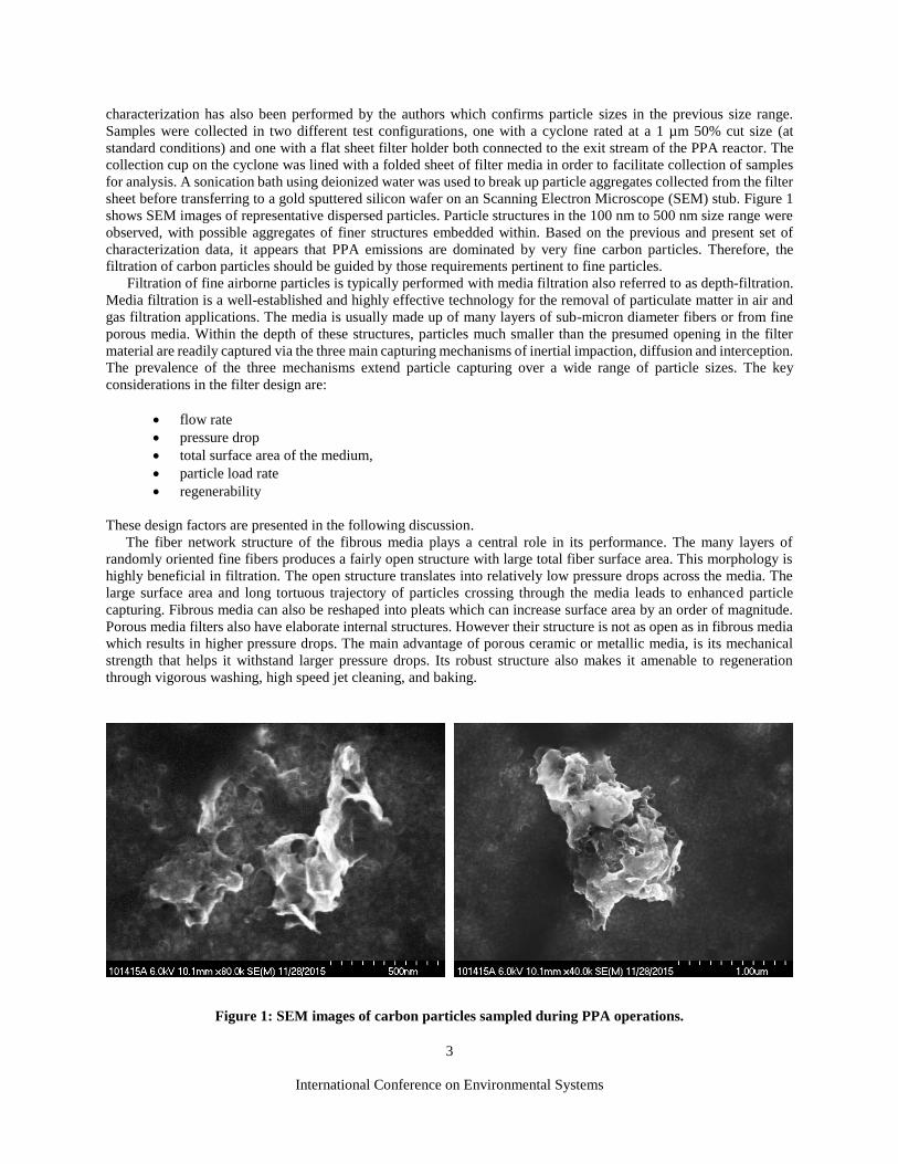
surface of the pleats. Initially no caking of the media pleat edges were observed. Figure 5a shows the pressure drop
history for all tests plotted sequentially over different days of testing. The initial pressure drop across the filter was
very low and it barely changed during the initial 24 hour period. However, some variations in the base value of pressure
drop were seen in the initial days of testing possibly due to minor differences in operating conditions on different days
and the low values of differential pressure close to the resolution of the transducer. Further testing for prolonged
periods provided filter life data. The large dip in pressure drop which occurred at the 39 hour mark was linked to a
regeneration of the reactor chamber after it had become coated with carbon. The dip in differential pressure was
followed by a recovery period during which the differential pressure quickly rose back up to pre-regeneration levels.
The pressure drop data exhibited an accelerated rate of increase at around the 32 hour mark and reached a level of 150
Pa. The filter life was stopped at this point, because although HEPA filters have been shown to operate up into the
250 Pa range, the rate of pressure drop increase at this point was of concern. Continued operation at excessive pressures
can produce a hydrodynamic load on the filter media that can potentially cause structural failure within the media or
where it bonds to the filter housing.
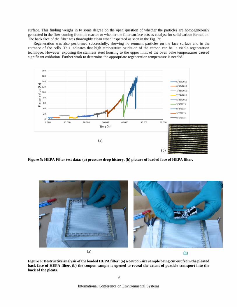
Destructive analysis of the post-tested HEPA filter was performed to determine the extent of particle dispersion
throughout the filter inlet surface. A small rectangular coupon was cut out of the back face of the pleated HEPA filter
element as shown in Fig 6 . The filter coupon was opened up to expose the range of particle capture, which showed
that the carbon particles reached nearly all the way into the back pleats.
In addition to the independent HEPA tests, a test to determine carbon load rate was conducted with a HEPA sheet
filter. After a 30 minute test a gravimetric analysis of the media indicated a loading rate of 41.6 mg/hr (close to the
rate reported by UMPQUA, although there was some particle losses on the walls of the inlet volume). During this
time a pressure drop increased at a rate of 23 Pa/hr.
The two-ply sheet filter tests were also performed by clamping the two filter media in front of the HEPA
cartridge filter. Media B which was rated at 95% efficiency appeared to capture over 75% of carbon loading, with a
pressure drop rate increase of 224 Pa/hr. This is a somewhat unexpected result since a minimum of 95% efficiency,
the rated efficiency, was expected. The unorthodox testing method of the two-ply media and screen configuration and
the accuracy of the microbalance could have contributed to the discrepancy. Based on the assumption that particles
were captured at close to the rated efficiency, one can deduce that virtually all the particles were in the range of the
MPPS. The ASHRAE lofted media appeared to capture 97% of carbon, with a pressure drop rate increase of 44.82
Pa/hr. This result is close to the rated efficiency and seems to indicate close to complete particle capturing. Even
though the media has a highly open structure it was able to capture a very large fraction of particles which is consistent
with the dominance of diffusional capturing throughout the internal media structure.
B. Diesel Particulate Filter
The diesel particulate filter (DPF), like the HEPA filter, also initially produced a small pressure drop, of 11 Pa,
as shown in Fig 7. After about six hours of operation however the pressure drop exhibited a transition to an accelerated
pressure drop of 2.9 Pa/min. The housing was opened up after testing to inspect the carbon build up and the condition
of the filter. Inspection of the front face of the filter, Fig. 7b, showed disproportionate particle dispersion. It appears
that the inlet jet created what seems like a splatter pattern on the front face of the filter. This is an indication that the
particles were entrained from the start in the incoming flow to create this pattern, rather than nucleating on the filter
International Conference on Environmental Systems
9
surface. This finding weighs in to some degree on the open question of whether the particles are homogeneously
generated in the flow coming from the reactor or whether the filter surface acts as catalyst for solid carbon formation.
The back face of the filter was thoroughly clean when inspected as seen in the Fig. 7c.
Regeneration was also performed successfully, showing no remnant particles on the face surface and in the
entrance of the cells. This indicates that high temperature oxidation of the carbon can be a viable regeneration
technique. However, exposing the stainless steel housing to the upper limit of the oven bake temperatures caused
significant oxidation. Further work to determine the appropriate regeneration temperature is needed.
Figure 5: HEPA Filter test data: (a) pressure drop history, (b) picture of loaded face of HEPA filter.
Figure 6: Destructive analysis of the loaded HEPA filter: (a) a coupon size sample being cut out from the pleated
back face of HEPA filter, (b) the coupon sample is opened to reveal the extent of particle transport into the
back of the pleats.
(a)
(b)
0
20
40
60
80
100
120
140
160
180
0.000 10.000 20.000 30.000 40.000 50.000 60.000
Pre
ssu
re d
rop
(Pa
)
Time (hr)
6/29/2015
6/30/2015
7/23/2015
7/24/2015
8/21/2015
9/3/2015
9/4/2015
9/2/2015
9/1/2015
(a) (b)

International Conference on Environmental Systems
10
Figure 7: DPF test data: (a) plot of pressure drop, (b) images of the inlet and (c) outlet faces of the ceramic
filter post-testing.
C. Scroll Filter
The Scroll Filter was operated for a short time period to determine its performance. The effect of the particle
loading on the MERV (Minimum efficiency reporting value) 13 media can be seen in Fig. 8a. There is an initial
constant pressure drop rise of 0.34 Pa/min which continued for about 2 hours before indexing or scrolling of the media
was attempted. During this initial period, the particle loading was observed to be uniform, as can be seen in Fig. 8b,
even though a particle impingement affect was generated as the inlet jet entered the entrance region of the filter housing
and reached the bottom wall. Also visible in the image is the reserve media rolled up on the supply spool on the right
side of the housing. The fact that the media remained clean in the face of long exposure at the inlet region shows that
the seals created by the media pressing against the inside of the frame and ancillary seals between the frame and
aluminum and Plexiglas wall were adequate, enough to prevent any perceptible particle to pass through. At the 2 hour
mark a scroll cycle was performed. The reactor continued operating nominally through the media changing operation.
As seen in Fig. 8a, the pressure almost instantly dropped down to the original clean media pressure drop level when
the media change out was complete. The same rate of pressure drop increase resumed after the media change out. A
second scroll cycle took place after about another hour of operation, with similar performance characteristics as in the
first scroll cycle. The slow rotation of the take up spool allowed adequate time to observe the performance of the
media changing event. No perceptible leakage of particles into the downstream volume was observed.
(a)
(b) (c)
0
50
100
150
200
250
0 2 4 6 8 10 12 14
Pre
ssu
re d
rop
(Pa
)
Time (hr)
7/2/2015
7/14/15 run 1
7/14/15 run 2
7/15/2015

International Conference on Environmental Systems
11
Figure 8: Scroll Filter test data: (a) plot of pressure drop history, (b) picture of the inside of the scroll filter
during testing.
VI. Discussion
The HEPA filter performed well maintaining a very low pressure drop, the lowest of the filters tested, for an
extended period of time. HEPA filters are designed to handle small increases in pressure drop over its lifetime.
However the media is somewhat fragile and may not tolerate more than a few hundred Pascal in pressure drop. Only
testing to failure under PPA operational conditions will give the ultimate filter life, but this was not feasible given the
limited time and resources needed to continue this type of testing. In addition, HEPA filters provide maximum
filtration over virtually the full range of particle sizes. The main issue with HEPA filters is that they are not
regenerable, and therefore the filter has to be sized properly for the full mission or replacement units need to be
additionally launched. Scaling up the HEPA filter by volume, and thus surface area, can increase operational life
proportionately if one assumes uniform particle coverage of the media surface.
The DPF was also able to effectively filter the carbon particles. No migration of particles were observed on the
face of downstream filter nor in the downstream volume of the ceramic filter housing after testing. The pressure drop
was higher than the HEPA and started increasing at a constant rate right after operation. As noted previously the
pressure drop rate reached a transition where it increased by more than 35 fold to initial 2.9 Pa/min. The period of
time for the pressure drop to reach concerning levels can be determine by the media’s mechanical strength. Iso-static
testing of a similar monolithic filter showed that the filter fails at about 99.6 kPa.9 This ultimate pressure drop is
significantly larger than the 50 Torr maximum pressure drop that can be sustained in the PPA. Over 45 hours of
operation can be expected before reaching the PPA system pressure drop. However, the excessive overloading of
carbon on the media at this prolonged exposure may alter in an undetermined way the effectiveness or required time
for regeneration. Because of the regenerability of the filter no replacement units are needed but supporting hardware
or system infrastructure will be needed to accommodate the high temperature regeneration of the filter.
The Scroll filter seemed to perform well during the particle loading and scrolling operations. The initial pressure
was slightly larger than that produced with the other filters due to the smaller exposed surface area of the media, but
still relatively low. The small rate of increase in pressure drop found during loading should allow for extended
operation over multiple hours. The maximum pressure drop that can be reached before a scroll operation is required
will be determine by the strength of media and the integrity of the seals to resist the hydrodynamic load and prevent a
breach of the particle flow past the filter. The scrolling operation was also successful, preventing particle penetration
through the seals during the scrolling process and recovering the initial pressure drop at the end of the scroll operation.
Ideally, the Scroll can operate for an indefinite span of time depending on the amount of reserved media carried in
the housing. The operational life of the Scroll Filter will depend on how much reserve media it can carry. Since the
reserved media can be maximally packed in the roll configuration, the service life can be extended with modest
Inlet jet impinges
on bottom wall
(a)
(b)
International Conference on Environmental Systems
12
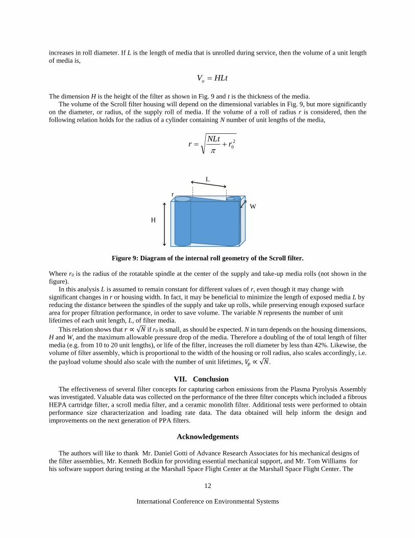
increases in roll diameter. If L is the length of media that is unrolled during service, then the volume of a unit length
of media is,
HLtVo
The dimension H is the height of the filter as shown in Fig. 9 and t is the thickness of the media.
The volume of the Scroll filter housing will depend on the dimensional variables in Fig. 9, but more significantly
on the diameter, or radius, of the supply roll of media. If the volume of a roll of radius r is considered, then the
following relation holds for the radius of a cylinder containing N number of unit lengths of the media,
2
0rNLt
r
Figure 9: Diagram of the internal roll geometry of the Scroll filter.
Where r0 is the radius of the rotatable spindle at the center of the supply and take-up media rolls (not shown in the
figure).
In this analysis L is assumed to remain constant for different values of r, even though it may change with
significant changes in r or housing width. In fact, it may be beneficial to minimize the length of exposed media L by
reducing the distance between the spindles of the supply and take up rolls, while preserving enough exposed surface
area for proper filtration performance, in order to save volume. The variable N represents the number of unit
lifetimes of each unit length, L, of filter media.
This relation shows that 𝑟 ∝ √𝑁 if r0 is small, as should be expected. N in turn depends on the housing dimensions,
H and W, and the maximum allowable pressure drop of the media. Therefore a doubling of the of total length of filter
media (e.g. from 10 to 20 unit lengths), or life of the filter, increases the roll diameter by less than 42%. Likewise, the
volume of filter assembly, which is proportional to the width of the housing or roll radius, also scales accordingly, i.e.
the payload volume should also scale with the number of unit lifetimes, 𝑉𝑝 ∝ √𝑁.
VII. Conclusion
The effectiveness of several filter concepts for capturing carbon emissions from the Plasma Pyrolysis Assembly
was investigated. Valuable data was collected on the performance of the three filter concepts which included a fibrous
HEPA cartridge filter, a scroll media filter, and a ceramic monolith filter. Additional tests were performed to obtain
performance size characterization and loading rate data. The data obtained will help inform the design and
improvements on the next generation of PPA filters.
Acknowledgements
The authors will like to thank Mr. Daniel Gotti of Advance Research Associates for his mechanical designs of
the filter assemblies, Mr. Kenneth Bodkin for providing essential mechanical support, and Mr. Tom Williams for
his software support during testing at the Marshall Space Flight Center at the Marshall Space Flight Center. The
H
W
L
L0
r

International Conference on Environmental Systems
13
support provide by the Life Support Systems (LSS) project under the Advanced Exploration Systems (AES)
program for this work is gratefully acknowledged.
References 1 Wheeler Jr, R.R., Hadley, N.M., Dahl, R.W., Abney, M.B., Greenwood, Z., Miller, L. and Medlen, A., 2012, July. Advanced
Plasma Pyrolysis Assembly (PPA) Reactor and Process Development. In 42nd International Conference on Environmental Systems
(p. 3553). 2Wheeler, R.R., Hadley, N.M., Wambolt, S.R. and Abney, M.B., 2014. Third Generation Advanced PPA Development. 44th
International Conference on Environmental Systems. 3Holtsnider, J.T., Wheeler, R.R., Dewberry, R.H., Abney, M.B. and Greenwood, Z.W., 2015. Hydrogen Purification in Support
of Plasma Pyrolysis of Sabatier Derived Methane. 45th International Conference on Environmental Systems. 4Greenwood, Z.W., Abney, M.B., Perry, J.L., Miller, L.A., Dahl, R.W., Hadley, N.M., Wambolt, S.R. and Wheeler, R.R., 2015.
Increased Oxygen Recovery from Sabatier Systems Using Plasma Pyrolysis Technology and Metal Hydride Separation. 5Green, R.D., Meyer, M.E., Agui, J.H., Berger, G.M., Vijayakumar, R., Abney, M.B. and Greenwood, Z., 2015.
Characterization of carbon particulates in the exit flow of a Plasma Pyrolysis Assembly (PPA) reactor. 45th International
Conference on Environmental Systems. 6Agui, J.H., Mackey, J.R., Vijayakumar, R., Seitz, T. and Bryg, V., 2010. Investigation of the Filtration of Lunar Dust Simulants
at Low Pressures. In AIAA Internation Conference on Environmental Systems, Barcelona, Spain. 7Dahl, R.W., Hadley, N.M., and Wheeler, R.R., Jr. , Plasma Pyrolysis Assembly Advanced Reactor Development, Phase III,
1st Year Final Report, NASA Contract NNM11AA34C, Marshall Space Flight Center, 2011. 8 Agui, J. and Vijayakumar, R., “Development of an Indexing Media Filtration System for Long Duration Space Missions,”
AIAA-2013-3486, AIAA 43rd International Conference on Environmental Systems, Vail, Colorado, 2013. 9 Lakhwani, S. and Hughes, K.W., 2005. Evaluation of a Stronger Ultra Thin Wall Corning Substrate for Improved
Performance. SAE 2005-01-1109.