Embed Size (px)
Citation preview
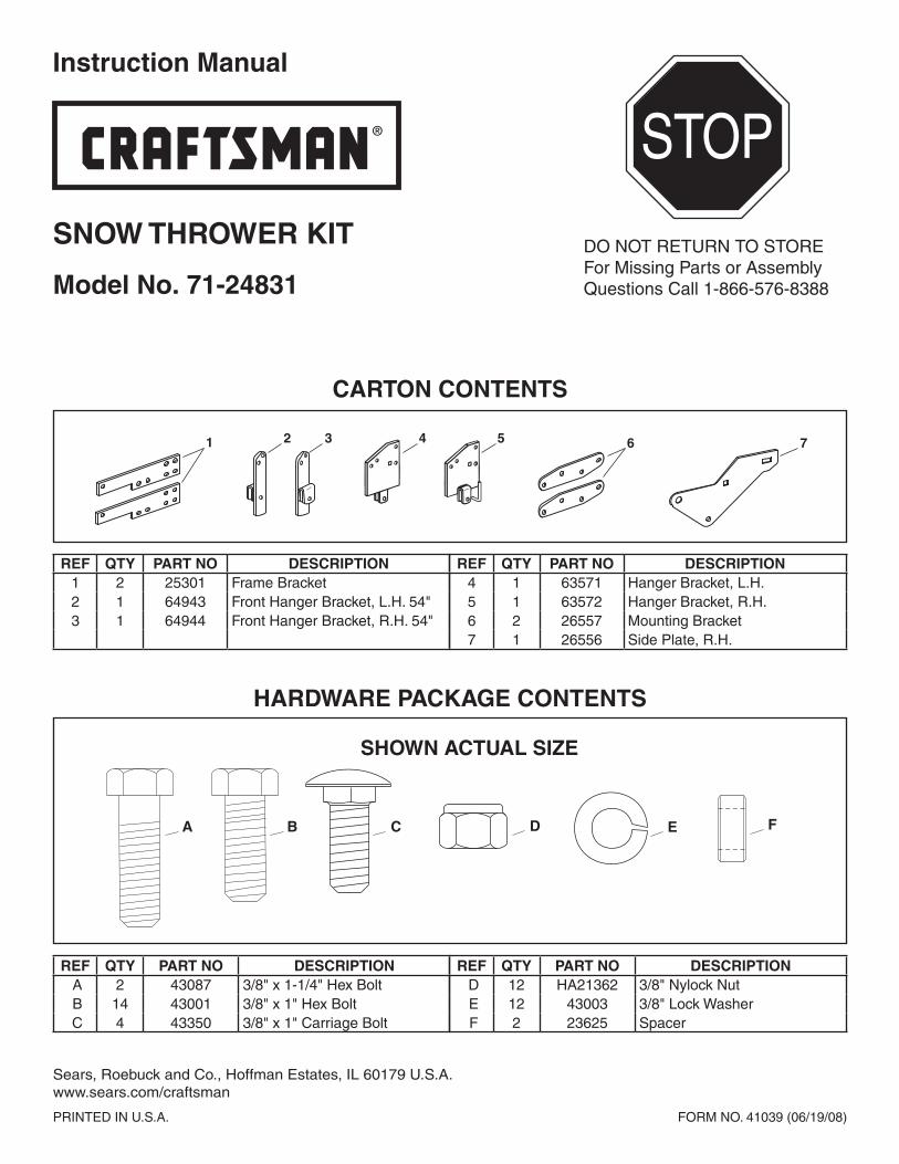
Instruction Manual
Model No. 71-24831
SNow Thrower KIT
® STOP
DO NOT RETURN TO STOREFor Missing Parts or AssemblyQuestions Call 1-866-576-8388
A B C F
SHOWN ACTUAL SIZE
D E
ref qTy parT No deScrIpTIoN A 2 43087 3/8" x 1-1/4" Hex Bolt B 14 43001 3/8" x 1" Hex Bolt C 4 43350 3/8" x 1" Carriage Bolt
ref qTy parT No deScrIpTIoN D 12 HA21362 3/8" Nylock Nut E 12 43003 3/8" Lock Washer F 2 23625 Spacer
hardware pacKaGe coNTeNTS
ref qTy parT No deScrIpTIoN 1 2 25301 Frame Bracket 2 1 64943 Front Hanger Bracket, L.H. 54" 3 1 64944 Front Hanger Bracket, R.H. 54"
ref qTy parT No deScrIpTIoN 4 1 63571 Hanger Bracket, L.H. 5 1 63572 Hanger Bracket, R.H. 6 2 26557 Mounting Bracket 7 1 26556 Side Plate, R.H.
1 3 5 64 2 7
carToN coNTeNTS
PRINTED IN U.S.A. FORM NO. 41039 (06/19/08)
Sears, Roebuck and Co., Hoffman Estates, IL 60179 U.S.A.www.sears.com/craftsman

2 Call 1-866-576-8388 for missing parts or assembly help DO NOT RETURN TO STORE
uSe The foLLowING INSTrucTIoNS IN pLace of STepS #1 Thru #46 IN The SNow Thrower MaNuaL.
FIGURE 2a RIGHT SIDE VIEW
STep 2: (See fIGure 2a or 2b)• Attach the R.H. side plate (supplied with the kit) to the
tractor. If you removed bolts as shown in figure 1a, install two 3/8" x 1" hex bolts and 3/8" lock washers as shown in figure 2a. If you removed nuts as shown in figure 1b, install two 3/8" x 1" carriage bolts, 3/8" lock washers and 3/8" nylock nuts as shown in figure 2b.
NOTE: If you remove the side plates from the tractor, be sure to reassemble bolts and nuts back into the frame.
SIDE PLATE (L.H.)supplied with snow thrower
STep 3: (See fIGure 3)• Attach the L.H. side plate (supplied with the snow
thrower) to the left side of the tractor frame in the same manner as the R.H. side plate.
FIGURE 3 LEFT SIDE VIEW
Right hand (R.H.) and left hand (L.H.) are determinedfrom the operators position while seated on the tractor.
STep 1: (See fIGure 1a or 1b)• Determine if your tractor has bolts like those shown in
figure 1a or 1b.• Remove either the hex bolts as shown in figure 1a or
the nuts as shown in figure 1b.• Repeat for the L.H. front suspension bracket.
FIGURE 1a RIGHT SIDE VIEW
REMOVE BOLTS
FRONT SUSPENSION BRACKET (R.H.)
FRONT SUSPENSION BRACKET (R.H.)
REMOVE NUTS
FIGURE 1b RIGHT SIDE VIEW
3/8" LOCK
WASHER3/8" x 1"HEX BOLT
R.H. SIDE PLATEsupplied with kit
FIGURE 2b RIGHT SIDE VIEW
3/8" NYLOCK NUT
R.H. SIDE PLATEsupplied with kit
3/8" LOCKWASHER
3/8" x 1"CARRIAGE BOLT
parTS ShowN IN Gray are SuppLIed wITh The KIT.

3Call 1-866-576-8388 for missing parts or assembly help DO NOT RETURN TO STORE
FIGURE 5 RIGHT SIDE VIEW
FIGURE 4 RIGHT SIDE VIEW
STep 5: (See fIGure 5)• Assemble the R.H. hanger bracket to the bottom hole
where the mower stop bracket was removed and to the upper hole under the front of the foot rest. Fasten with two 3/8" x 1" hex bolts, 3/8" lock washers and 3/8" nylock nuts. (On tractors with muffler guards, slide the hanger bracket between the guard and the tractor frame.)
STep 4: (See fIGure 4)• Remove the mower stop bracket and its two bolts and
nuts from the R.H. side of the tractor frame.• If the tractor has a muffler guard at the front of the
R.H. foot rest, remove the bottom bolt and nut, and the washer which is located between the guard and the tractor frame.
• Remove the two bolts from the bottom of both the R.H. and L.H. foot rests.
MUFFLER GUARD(only on modelswith side muffler)
REMOVEBRACKET
REMOVE BOLTS, NUTS& WASHERS SHOWN
3/8" x 1" HEX BOLT
3/8" LOCK WASHER
3/8" NYLOCKNUT
R.H. HANGER BRACKET
STep 6: (See fIGure 6)• Assemble the L.H. hanger bracket to the left side of
the tractor frame using two 3/8" x 1" hex bolts, two 3/8" lock washers and two 3/8" nylock nuts.
FIGURE 7 LEFT SIDE VIEW
FIGURE 6 LEFT SIDE VIEW
STep 7: (See fIGure 7)• Assemble a frame bracket to the L.H. foot rest and
sway bar bracket. Use two 3/8" x 1-1/4" hex bolts, two 3/8" lock washers and one spacer.
• Assemble a shoulder bolt (P) and a 3/8" flanged nut (BB) (both supplied with the snow thrower) to the frame bracket.
3/8" x 1" HEX BOLT
3/8" LOCK WASHER
3/8" NYLOCKNUT
L.H. HANGER BRACKET
3/8" LOCKWASHER
FRAMEBRACKET
3/8" x 1-1/4"HEX BOLT
SWAY BARBRACKET
SPACER
SHOULDERBOLT (P)(snow thrower)
3/8" FLANGED NUT (BB)(snow thrower)
If you have a 54" mower deck skip to step #9. For smaller decks use the following instructions.

4 Call 1-866-576-8388 for missing parts or assembly help DO NOT RETURN TO STORE
FIGURE 8 RIGHT SIDE VIEW
STep 8: (See fIGure 8)• Assemble a frame bracket to the R.H. foot rest. Use
two 3/8" x 1" hex bolts and two 3/8" lock washers.• Assemble a shoulder bolt (P) and a 3/8" flanged nut
(BB) (both supplied with the snow thrower) to the frame bracket.
• Proceed to step #14 on page 6.
3/8" LOCKWASHER
FRAMEBRACKET
3/8" x 1"HEX BOLT
SHOULDERBOLT (P)(snow thrower) 3/8" FLANGED NUT (BB)
(snow thrower)
STep 9: (See fIGure 9)Only for 54" mower decks• Remove and store the mower stop bracket and bolt
from both sides of the tractor frame.• Remove the two bolts from the bottom of the foot
rests on both sides of the tractor frame.
FIGURE 9 RIGHT SIDE VIEW
Steps #9 thru #13 for tractors with 54" mower decks.
REMOVEREMOVE
54" MOWER DECKS
FIGURE 10 RIGHT SIDE VIEW
STep 10: (See fIGure 10)Only for 54" mower decks• Assemble the 54" R.H. hanger bracket to the holes on
the right side of the tractor frame where the mower stop bracket was removed. Fasten with two 3/8" x 1" hex bolts, two 3/8" lock washers and one 3/8" nylock nut.
3/8" x 1"HEX BOLT
3/8" LOCK WASHER
3/8" LOCKWASHER
3/8" NYLOCKNUT
R.H. HANGER BRACKET (54")
3/8" x 1" HEX BOLT
54" MOWER DECKS
FIGURE 11 LEFT SIDE VIEW
STep 11: (See fIGure 11)Only for 54" mower decks• Assemble the 54" L.H. hanger bracket to the holes
where the mower stop bracket was removed on the left side of the tractor frame. Fasten with two 3/8" x 1" hex bolts, two 3/8" lock washers and two 3/8" nylock nuts
3/8" LOCK WASHER
L.H. HANGER BRACKET (54")
3/8" x 1" HEX BOLT
3/8" NYLOCK NUT
54" MOWER DECKS

5Call 1-866-576-8388 for missing parts or assembly help DO NOT RETURN TO STORE
FIGURE 12 LEFT SIDE VIEW
STep 12: (See fIGure 12)Only for 54" mower decks• Assemble a frame bracket to the L.H. foot rest. Use
two 3/8" x 1-1/4" hex bolts, two 3/8" lock washers and two spacers.
• Assemble a shoulder bolt (P) and a 3/8" flanged nut (BB) (both supplied with the snow thrower) to the frame bracket.
3/8" LOCKWASHER
FRAMEBRACKET
3/8" x 1-1/4"HEX BOLT
SPACER SPACERSHOULDERBOLT (P)(snow thrower)3/8" FLANGED NUT (BB)
(snow thrower)
FIGURE 13 RIGHT SIDE VIEW
STep 13 (See fIGure 13)Only for 54" mower decks• Assemble a frame bracket to the R.H. foot rest. Use
two 3/8" x 1" hex bolts and two 3/8" lock washers.• Assemble a shoulder bolt (P) and a 3/8" flanged nut
(BB) (both supplied with the snow thrower) to the frame bracket.
5/16" NYLOCKNUT (CC)
5/16" x 3/4"HEX BOLT (E)
SUSPENSIONARM
STep 14: (See fIGure 14)• Attach the two suspension arms to the outside of the
clutch/idler assembly using two 5/16" x 3/4" hex bolts (E) and 5/16" nylock nuts (CC) for each arm.
3/8" NYLOCKNUT
3/8" x 1"HEX BOLT MOUNTING
BRACKET
STep 15: (See fIGure 15)• Attach the two mounting brackets to the front of the
clutch/idler assembly using four 3/8" x 1" hex bolts and 3/8" nylock nuts. Place the frame brackets on the outside of the assembly frame.
FIGURE 14
FIGURE 15
3/8" LOCKWASHER
FRAMEBRACKET
3/8" x 1"HEX BOLT
SHOULDERBOLT (P)(snow thrower)
3/8" FLANGED NUT (BB)(snow thrower)
aLL parTS IN The foLLowING INSTrucTIoNS are SuppLIed wITh The SNow Thrower excepT for ThoSe parTS ShowN IN Gray, whIch are SuppLIed wITh The KIT.
54" MOWER DECKS
54" MOWER DECKS

6 Call 1-866-576-8388 for missing parts or assembly help DO NOT RETURN TO STORE
STep 17: (See fIGure 17)• Turn the clutch/idler assembly right side up.• Insert the tensioning chains through the holes shown
on the left and right sides. Attach the ends of the chains to the springs on the upper and lower idler arms.
• Install a 3/32" hairpin cotter (LL) into the left side chain. If the tractor's engine pulley is smaller than 6", place it in link #3 from the spring. For larger engine pulleys, place it in link #6 from the spring.
3/8" HEXLOCK NUT(DD)
SPRING (GG)
UPPERIDLERARM
BOTTOM
VIEW
STep 16: (See fIGure 16)• Turn the clutch/idler assembly upside down.• Hook the end of the spring (GG) onto the bottom of the
bolt and nut which secure the idler pulley to the upper idler arm. Hold the bolt head and assemble a 3/8" hex lock nut (DD) onto the bolt, leaving enough space for the spring to pivot freely between the two nuts.
LEFT & RIGHTTENSIONINGCHAINS (PP)
3/32" HAIRPINCOTTER (LL)IN LINK #3 or #6
STep 18: (See fIGure 18)• Two different length drive belts are supplied with your
snow thrower. Select the shorter belt with #46989 printed on it.
• Slightly loosen the hex bolt next to the upper idler pulley. Install the drive belt down between the hex bolt and the upper idler pulley with the flat side of the belt against the pulley. Retighten the hex bolt.
• Loop the belt around the large v-pulley, placing it between the v-pulley and the hex bolt next to the pulley.
HEX BOLTS
DRIVE BELT#46989
UPPER IDLERPULLEY
fIGure 16 VIewed froM BoTToM
FIGURE 17
FIGURE 18

7Call 1-866-576-8388 for missing parts or assembly help DO NOT RETURN TO STORE
STep 19: (See fIGure 19)Only for mower decks smaller than 54"• Attach the rear of the clutch/idler assembly to the tractor
frame by sliding the notched arms of the assembly onto the shoulder bolts assembled to the frame brackets. Lift the front of the assembly, positioning the upper idler pulley so that it clears the engine pulley. Attach the front of the assembly to the hanger brackets using two pivot lock pins (MM) and two hairpin cotters (KK).
PIVOT LOCK PIN (MM)
HAIRPIN COTTER (KK)
STep 20: (See fIGure 20)Only for 54" mower decks • Attach the rear of the clutch/idler assembly to the tractor
frame by sliding the notched arms of the assembly onto the shoulder bolts assembled to the frame brackets. Lift the front of the assembly, positioning the upper idler pulley so that it clears the engine pulley. Attach the front of the assembly to the hanger brackets using two pivot lock pins (MM) and two hairpin cotters (KK).
HAIRPIN COTTER (KK)
PIVOT LOCK PIN (MM)
54" MOWER DECKS
FIGURE 19
FIGURE 20
reTurN To STep #64 IN The SNow Thrower MaNuaL aNd fINISh aSSeMBLING The SNow Thrower.
STep 21: (See fIGure 21)• Loosen the two hex bolts and nuts which fasten the top
of the tractor drawbar to the rear of the tractor frame.• Assemble the notched end of the side brace arms
down onto both loosened bolts. Do not tighten yet.• Fasten the weight tray to the drawbar using a 1/2" x 1-1/4" hex bolt (A), a 1/2" washer (V) and a 1/2"
nylock nut (EE). Do not tighten yet.• Fasten the weight tray to the side brace arms using
two 5/16" x 1" carriage bolts (N) and two 5/16" nylock nuts (CC). Do not tighten yet.
• Fasten the cross brace to the side brace arms using two 5/16" x 1" carriage bolts (N) and two 5/16" nylock nuts (CC). Tighten all loose bolts at this time.
FIGURE 21 VIEWED FROM REAR
5/16" x 1"CARRIAGEBOLT (N)
SIDE BRACE ARM
WEIGHT TRAY
5/16" NYLOCKNUT (CC)
1/2" x 1-1/4"HEX BOLT (A)
LOOSENED NUT AND BOLT
CROSSBRACE
1/2" NYLOCK NUT (EE)
1/2" WASHER (V)
coMpLeTe STepS #47 Thru #59 IN The SNow Thrower MaNuaL, TheN reTurN To STep 21 oN ThIS paGe.

® Registered Trademark / TM Trademark / SM Service Mark of Sears Brands, LLC ® Marca Registrada / TM Marca de Fábrica / SM Marca de Servicio de Sears Brands, LLC MC Marque de commerce / MD Marque déposée de Sears Brands, LLC © Sears Brands, LLC
Get it fixed, at your home or ours!Your Home
For repair – in your home – of all major brand appliances,lawn and garden equipment, or heating and cooling systems,
no matter who made it, no matter who sold it!For the replacement parts, accessories and
owner’s manuals that you need to do-it-yourself. For Sears professional installation of home appliancesand items like garage door openers and water heaters.
1-800-4-MY-HOME® (1-800-469-4663)Call anytime, day or night (U.S.A. and Canada)
www.sears.com www.sears.ca For expert home solutions advice: www.managemyhome.com
Our Home For repair of carry-in items like vacuums, lawn equipment,
and electronics, call or go on-line for the location of your nearest Sears Parts & Repair Service Center
1-800-488-1222 (U.S.A.) 1-800-469-4663 (Canada)Call anytime, day or night
www.sears.com www.sears.ca
To purchase a protection agreement on a product serviced by Sears: 1-800-827-6655 (U.S.A.) 1-800-361-6665 (Canada)
Para pedir servicio de reparación a domicilio, y para ordenar piezas:
1-888-SU-HOGAR®
(1-888-784-6427)
Au Canada pour service en français:1-800-LE-FOYERMC
(1-800-533-6937)www.sears.ca


![TECHNICAL ANALYSIS OF HYDROGEN PRODUCTION FROM …257... · FIGURE 5: RM3 Device Design with dimensions [20]. FIGURE 6: RM3 Device Design and Working from the Side View [20] FIGURE](https://img.pdfslide.us/doc/110x75/60da6ba92a8ad356996ab9b7/technical-analysis-of-hydrogen-production-from-257-figure-5-rm3-device-design.jpg)