Embed Size (px)
Citation preview
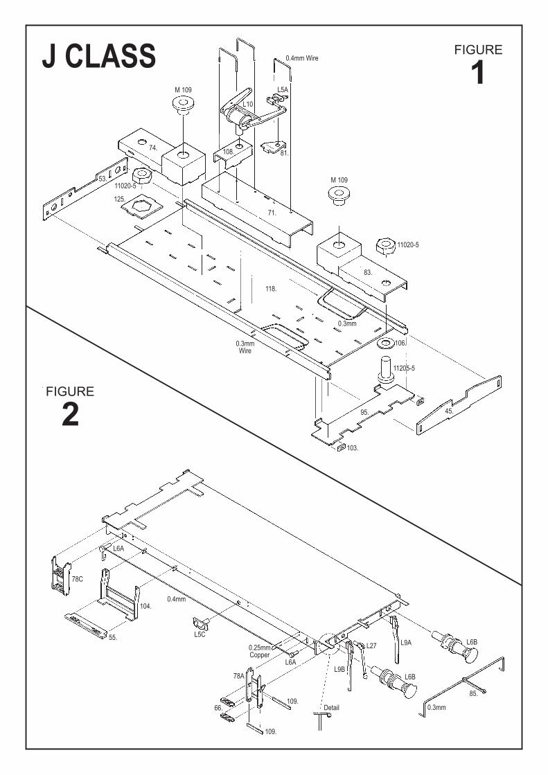
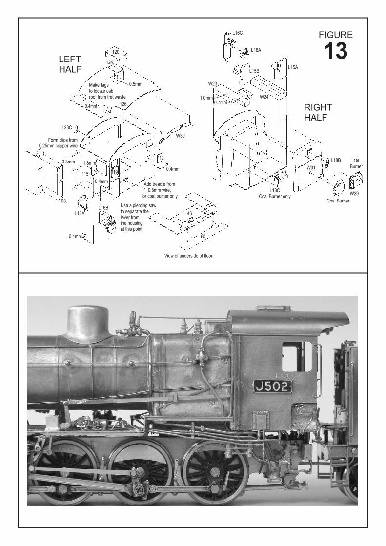
FIGURE
FIGURE
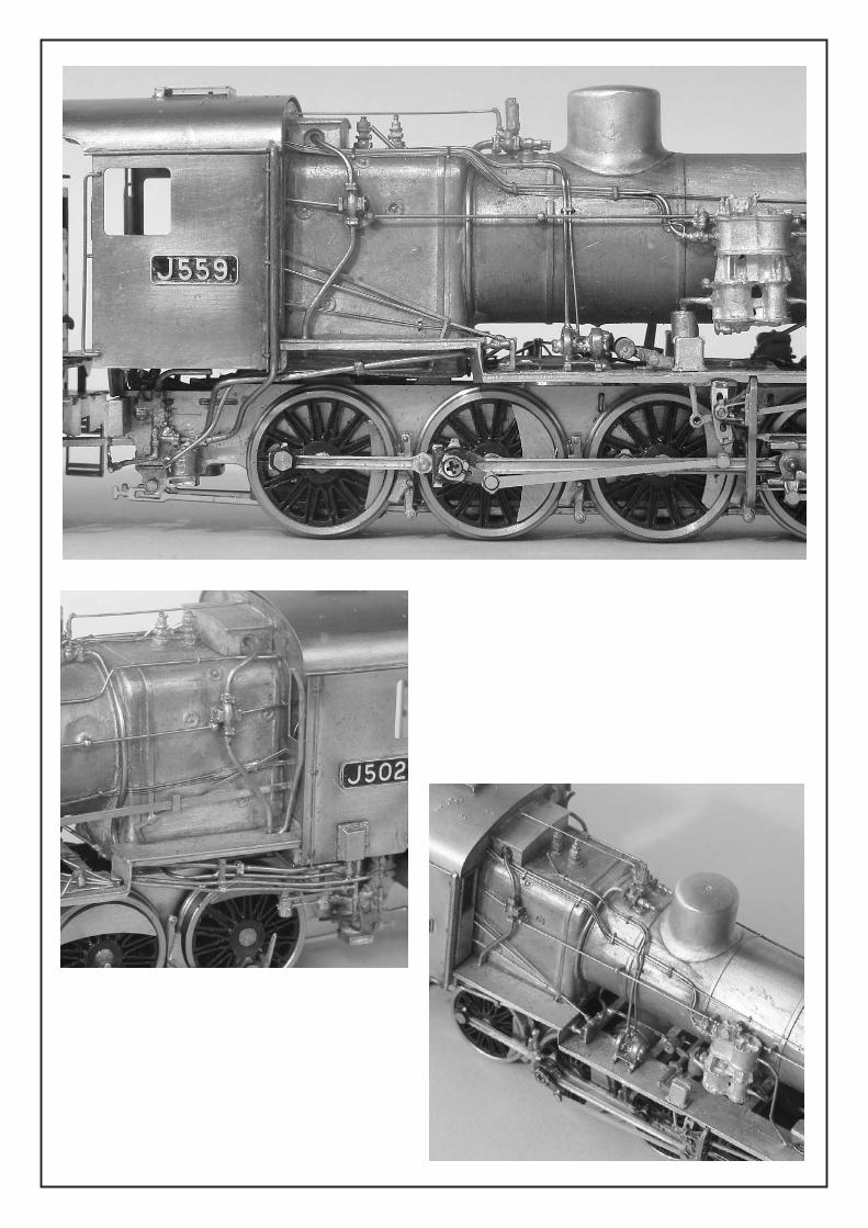
1J CLASS
2
53.
125.
118.
11020-5
11020-5
11205-5
74.
M 109
M 109
0.4mm Wire
0.3mmWire
0.25mmCopper
0.3mm
0.4mm
0.3mm
104.
55.
L5A
L10
81.
71.
83.
95. 45.
L6A
L6AL9B
L6B
L6BL9AL27
Detail
78A
66.
109.
109.85.
L5C
78C
103.
106.
108.
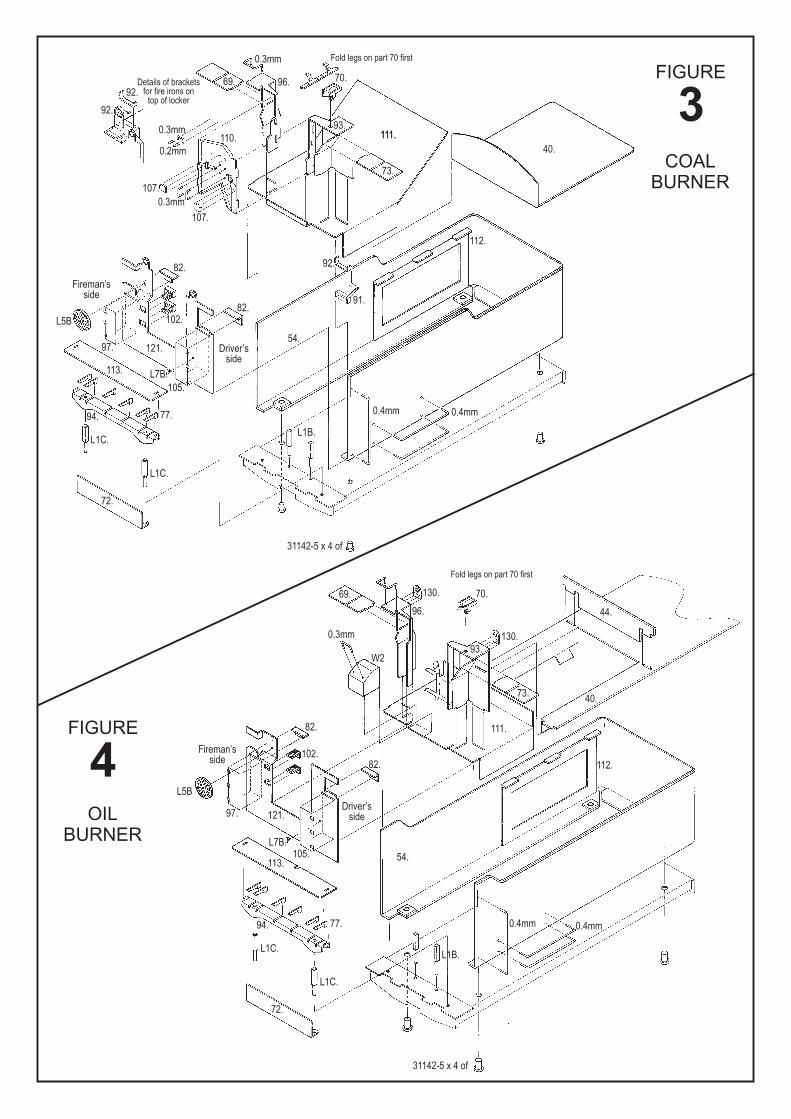
FIGURE
3
FIGURE
4
92.69.
110.
96.
93.
92.
54.97.
97.
94. 77.
72.
82.
82.
69.
96.
93.
73.40.
44.
130.
130.
111.
112.
54.
82.
82.
102.
102.
121.
121.
113.
113.
105.
105.
L7B.
L7B.
L1C.
L1C.
94. 77.
72.
L1C.
L1C.
L1B.
L1B.
31142-5 x 4 of
31142-5 x 4 of
91.
112.
73.
111.111.
40.
70.
70.
0.3mm
0.3mm
0.4mm 0.4mm
W2
0.3mm
0.3mm
0.4mm 0.4mm
0.2mm
92.
107.
L5B
L5B
107.
Details of bracketsfor fire irons on
top of locker
Driver’sside
Driver’sside
Fireman’sside
Fireman’sside
Fold legs on part 70 first
Fold legs on part 70 first
COAL
BURNER
OIL
BURNER
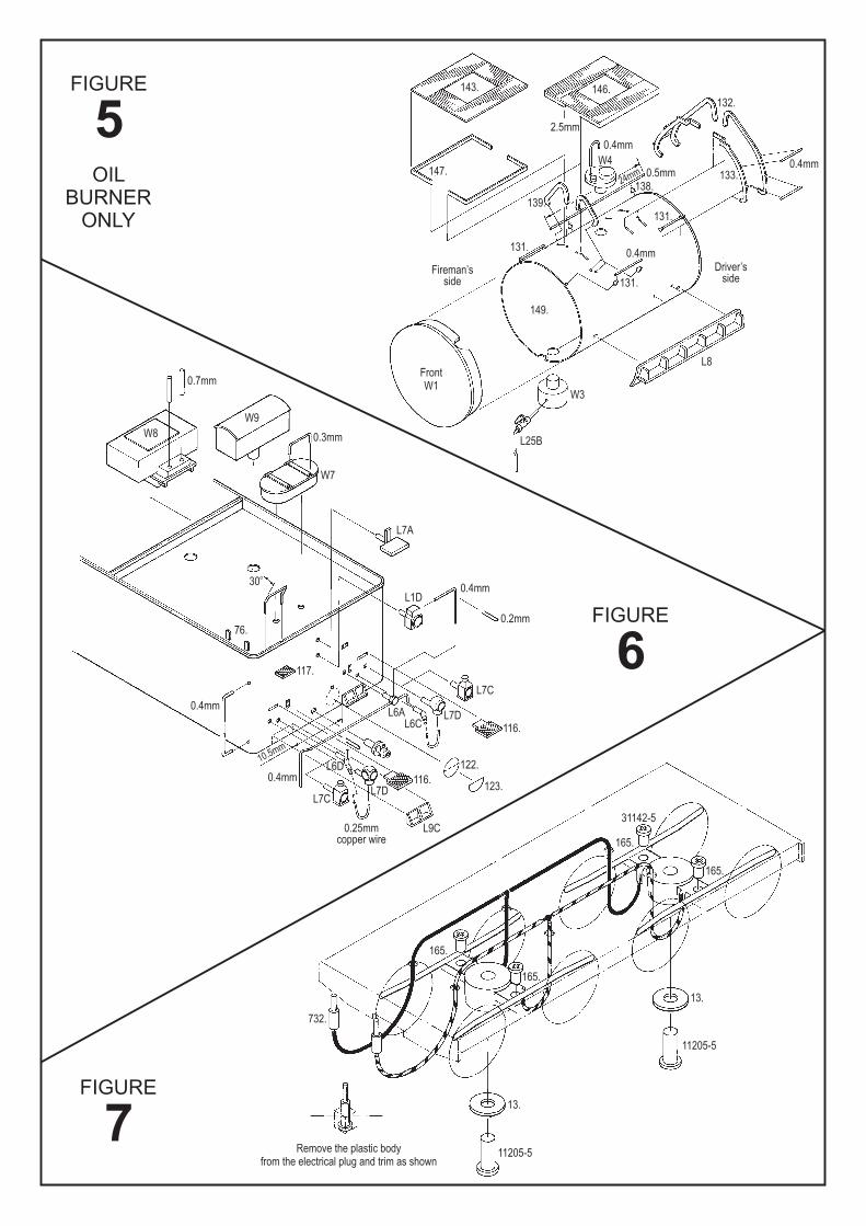
FIGURE
FIGURE
FIGURE
5
6
7
143. 146.132.
133.
131.
131.
131.
149.
W3
W8
W9
W7
0.7mm
0.3mm L25B
L7A
76.
30o
L1D
L7C
L7C
116.
122.
123.
165.
165.
165.
732.
13.
Remove the plastic bodyfrom the electrical plug and trim as shown
11205-5
11205-5
31142-5
13.
165.
116.
117.
L7D
L7D
L9C
L6A
L6D
L6C
0.4mm
0.4mm
0.4mm
0.2mm
0.25mmcopper wire
L8FrontW1
139.
2.5mm
0.4mm
24mm
10.5mm
0.4mm
W4 0.4mm0.5mm147.
138.
Fireman’sside
Driver’sside
OIL
BURNER
ONLY
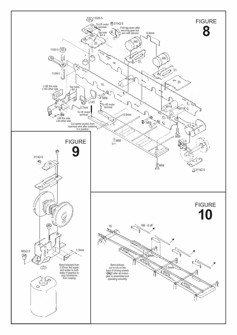
FIGURE
FIGURE
FIGURE
8
10
9
11020-5
31142-5
22.
14.
15.
10.
M118
M118M118
3.
M58
M58
M58
68.
6.
M2x2.0
11.
0.5m
m 1.5mm
166 - 8 off
0.5mm
0.5mm
19.
0.5mm
0.7mm
L3
7.
31142-5
31142-5
M58
M58
L14C
17.
21.
21.
20.
W6
W6
0.4mm
To-VE motorterminal
To-VE motorterminal
To-VE motorterminal
L4B this sideL4A other side
L14E this sideL14D other side
11208-5
11020-5
4.
Cut centre section fromrearmost wire after soldering
it in position
Bend brackets from0.25mm fret wasteand solder to bothsides of gearbox to
stop hornblocksfrom rotating
Bend pickupsout to rub on the
back of driving wheelsafter all motion
gear is assembled andoperating smoothly
ONLY
Fold tag down aftersecuring gear boxarm with siliconeTap hole
M1.4
Tap holesM1.4
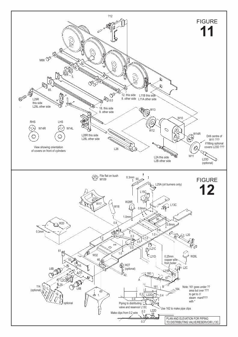
FIGURE
FIGURE
11
12
?12
M86
5.
18. this side9. other side
L2A this sideL2B other side
L11B this sideL11A other side
W13
W12
W10
W14RDrill centre of
W11 ???if fitting optional
covers L23D ???
W11L23D(optional)
8.0
12. this side8. other side
65.
L29Rthis sideL29L other side
View showing orientationof covers on front of cylinders
File flat on bushM109
W17W18
W28R
0.3mm
0.8mm
0.9
0.8
0.4
Use 162 to make pipe clips
Make clips from 0.2 wire
0.4
0.2 L22D
0.3
Piping to distributing
valve and reservoir L13C
PLAN AND ELEVATION FOR PIPINGTO DISTRIBUTING VALVE/RESERVOIR L13C
0.3
0.3mm
0.3
0.5
0.5
1.01.0
1.0W32
W20
46.
42.
L21D
L21C
L2CL21B
67.
160.
161.164.
L22D
Note: 161 goes under ??area but over ???to get to ///steam manif???with *
A
B
0.25mmcopper wirefrom boiler
L20
W28L
61.
16.
52.L6B
L6B
1.
114.(optional)
W27(optional)
L2C
L29
63.
1.0
0.8mm
1.0mm
L15C
L13C
90.
90.
L25A (oil burners only)
RHS
W14R W14L
L28R this sideL28L other side
LHS
L26
optional
FIGURE
13
L16C
120.
124.
126.
115.
W30
119.
119.
98.
46.
60.
View of underside of floor
L16AL16B
L23C
Make tagsto locate cabroof from fret waste
0.5mm
0.3mm
0.4mm
0.4mm
0.4mm
Add treadle from0.5mm wire,
for coal burner only
Use a piercing sawto separate thelever fromthe housingat this point
1.8mm
Form clips from0.25mm copper wire
0.4mm
L18A
L15BL15A
L18B
W31
W29
Coal Burner
L18CCoal Burner only
OilBurner
W23
W241.0mm0.7mm
LEFT
HALF
RIGHT
HALF
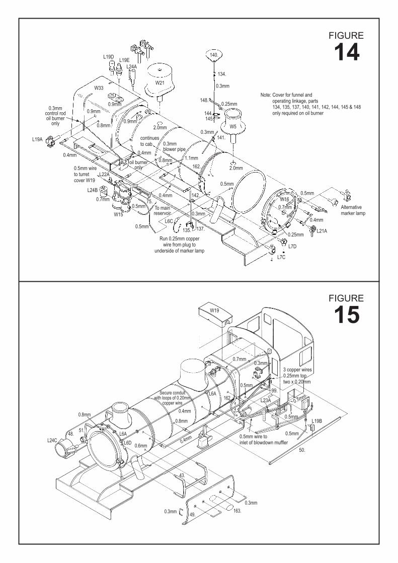
FIGURE
14
FIGURE
15
L19DL19E
L24A
W21W33
140.
Note: Cover for funnel andoperating linkage, parts134, 135, 137, 140, 141, 142, 144, 145 & 148only required on oil burner
148.
141.
162.
142.75.
W15
137.135.
L6C
To mainreservoir
Run 0.25mm copperwire from plug to
underside of marker lamp
144.145.
W5
134.
0.3mm
0.3mm
0.3mm
0.4mm
0.4mm0.4mm
oil burneronly
0.3mmcontrol rodoil burner
only
0.5mm
0.7mm
L24B
L22A
0.5mm
0.5mm wireto turretcover W19
0.8mm 1.1mm
0.3mmblower pipe
0.9mm
0.5mm
0.5mm
0.4mm
L21A
Alternativemarker lamp
L7D
L7C
0.25mm
W16
W19
0.7mm0.3mm
0.7mm
L19B
L23A
99.
0.5mm
0.5mm
0.5mm
0.4mm
0.4mm
0.8mm
0.8mm
0.6mm
0.3mm
0.3mm
162.L6A
L6A
L24C
51.48.
49.163.
43.
L6D
Secure conduitwith loops of 0.20mm
copper wire
0.5mm wire toinlet of blowdown muffler
50.
3 copper wires0.25mm toptwo x 0.20mm
0.7mm
2.0mm
2.0mm
continuesto cab
0.25mm
0.9mm
0.9mm
0.8mm
L19A