Embed Size (px)
Citation preview
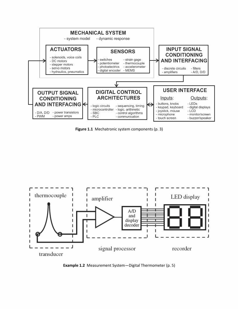
Figure 1.1 Mechatronic system components (p. 3)
Example 1.2 Measurement System—Digital Thermometer (p. 5)

Figure 2.2 Electric circuit terminology (p. 13)

Table 2.2 Resistor color band codes (p. 18)

Figure 2.13 Kirchhoff’s voltage law (p. 22)
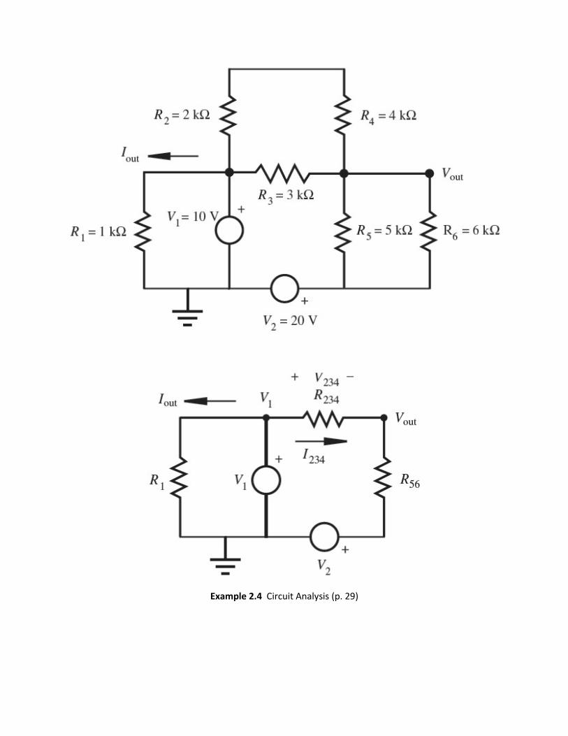
Example 2.4 Circuit Analysis (p. 29)

Figure 2.18 Real voltage source with output impedance (p. 31)
Figure 2.21 Real ammeter with input impedance (p. 32)
Figure 2.22 Real voltmeter with input impedance (p. 32)

Figure 2.28 Sinusoidal waveform (p. 37)
Figure 2.29 Sinusoidal signal DC offset (p. 38)
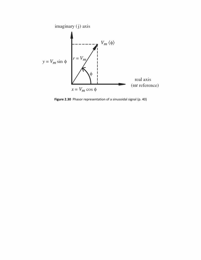
Figure 2.30 Phasor representation of a sinusoidal signal (p. 40)

Example 2.7 AC Circuit Analysis (p. 42)

Figure 3.2 pn Junction characteristics (p. 78)
Figure 3.3 Silicon diode (p. 79)
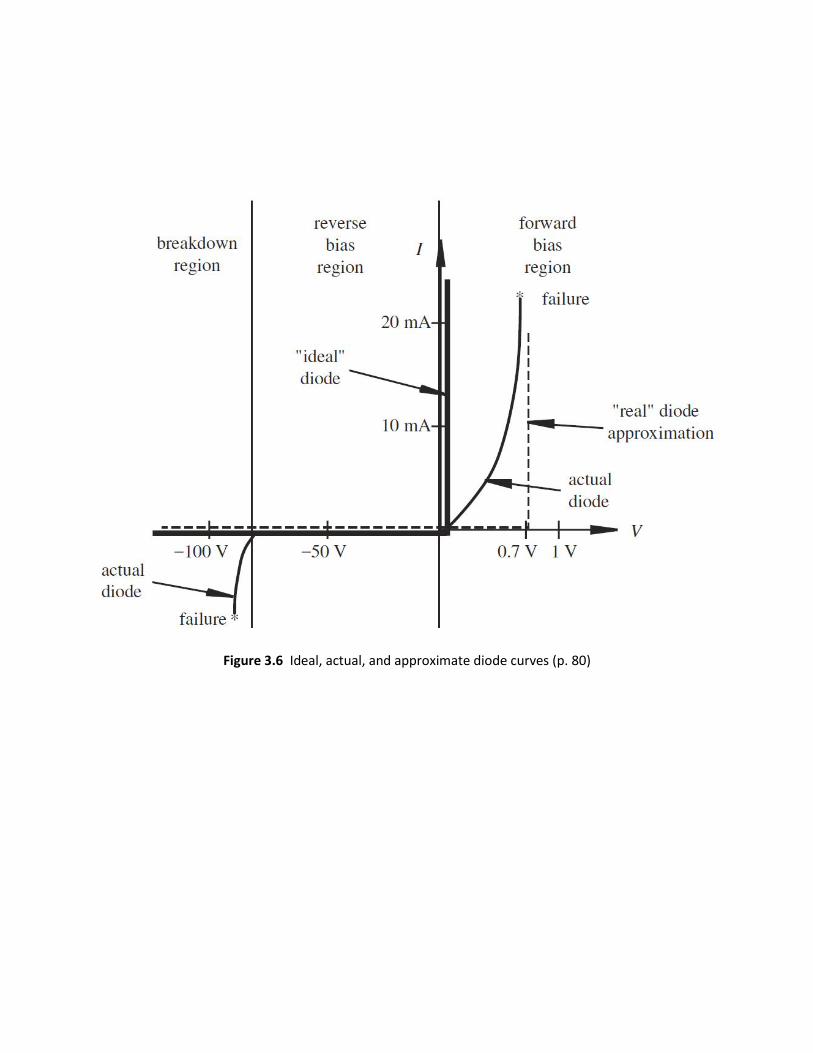
Figure 3.6 Ideal, actual, and approximate diode curves (p. 80)

Figure 3.9 Inductive load flyback protection (p. 83)
Figure 3.10 Flyback action (p. 84)

Figure 3.11 Light-emitting diode (p. 86)
Figure 3.13 Typical LED circuit in digital systems (p. 86)
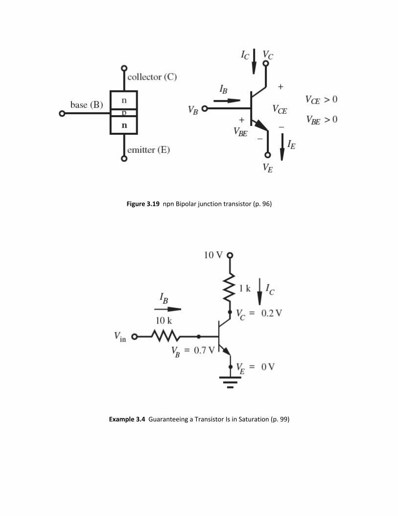
Figure 3.19 npn Bipolar junction transistor (p. 96)
Example 3.4 Guaranteeing a Transistor Is in Saturation (p. 99)

Figure 6.1 Analog and digital signals (p. 206)
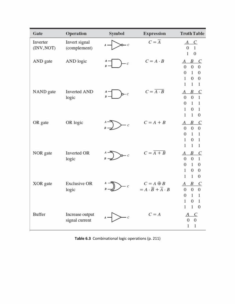
Table 6.3 Combinational logic operations (p. 211)
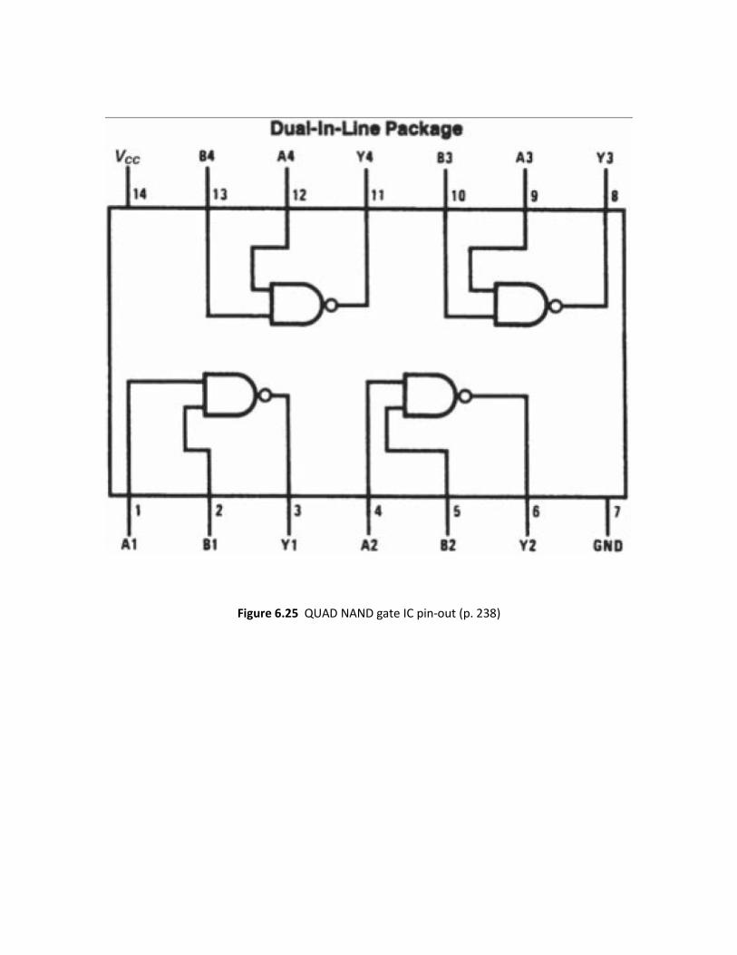
Figure 6.25 QUAD NAND gate IC pin-out (p. 238)

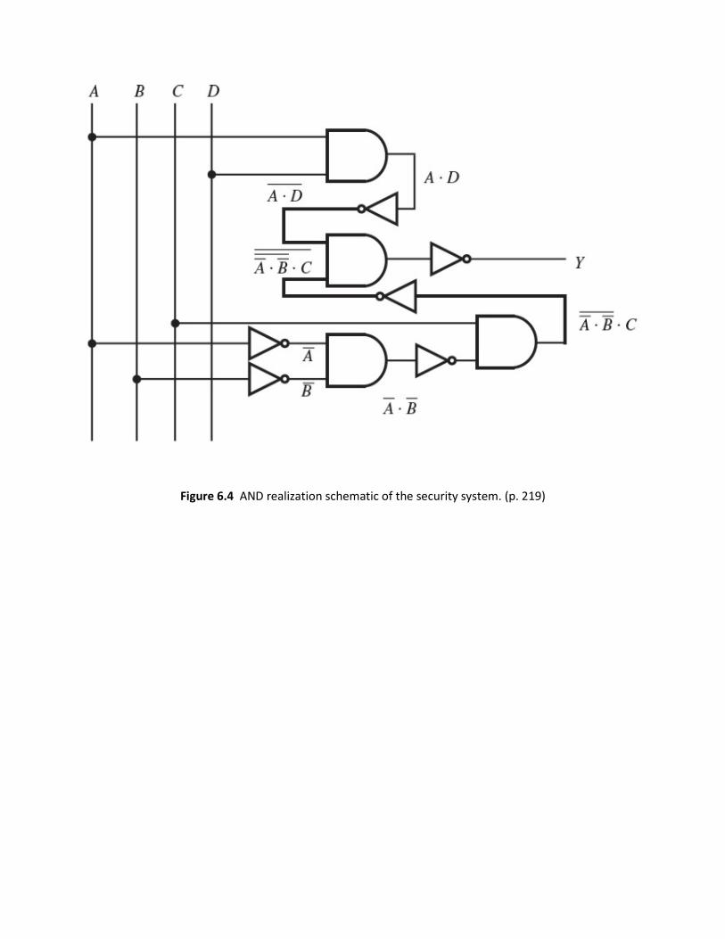
Figure 6.4 AND realization schematic of the security system. (p. 219)

Sum Of Products (SOP)
Product of Sums (POS)
EXAMPLE 6.4 Example 6.4 Sum of Products and Product of Sums (p. 220)
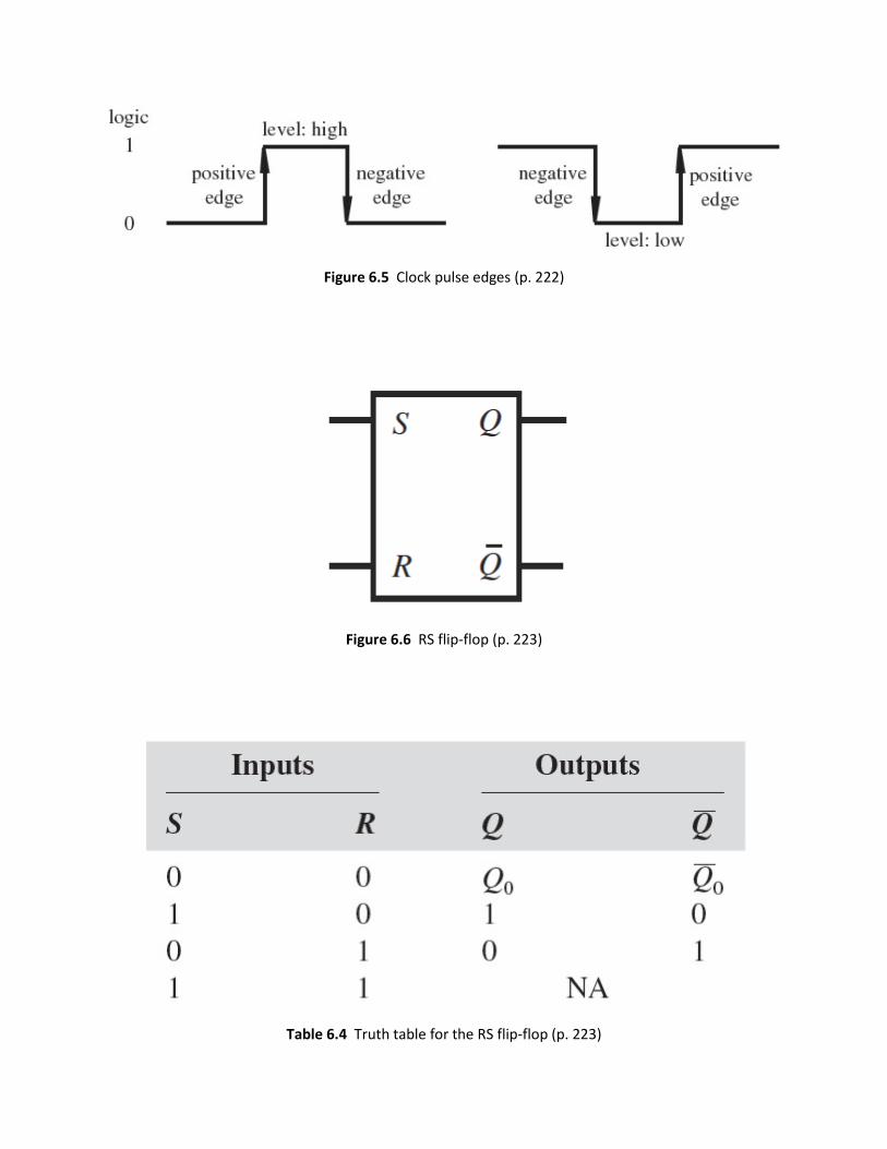
Figure 6.5 Clock pulse edges (p. 222)
Figure 6.6 RS flip-flop (p. 223)
Table 6.4 Truth table for the RS flip-flop (p. 223)

Figure 6.7 RS flip-flop internal design and timing (p. 224)
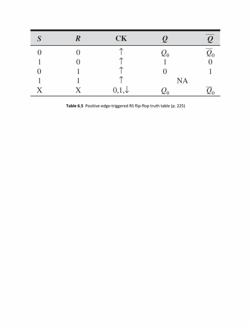
Table 6.5 Positive-edge-triggered RS flip-flop truth table (p. 225)

Figure 6.16 Switch bounce (p. 230)
Figure 6.17 Switch debouncer circuit (p. 223)
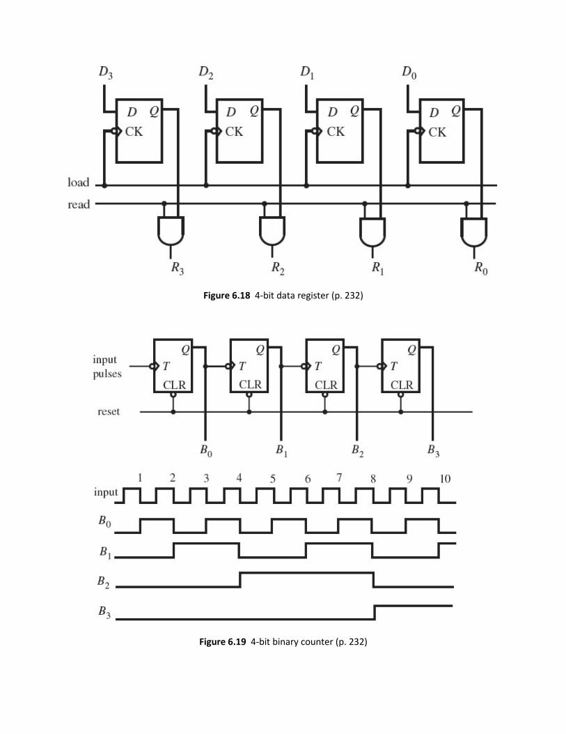
Figure 6.18 4-bit data register (p. 232)
Figure 6.19 4-bit binary counter (p. 232)
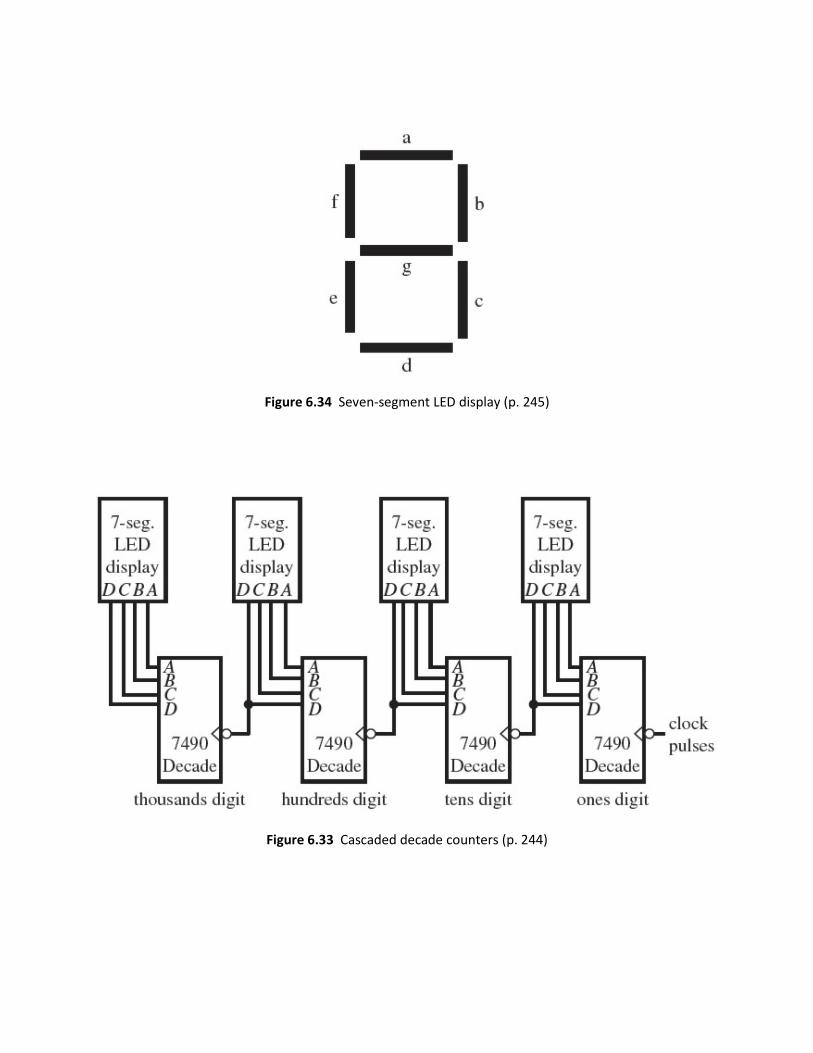
Figure 6.34 Seven-segment LED display (p. 245)
Figure 6.33 Cascaded decade counters (p. 244)

Figure 6.42 Block diagram of the 555 IC (p. 248)
Figure 6.43 One-shot timing (p. 250)
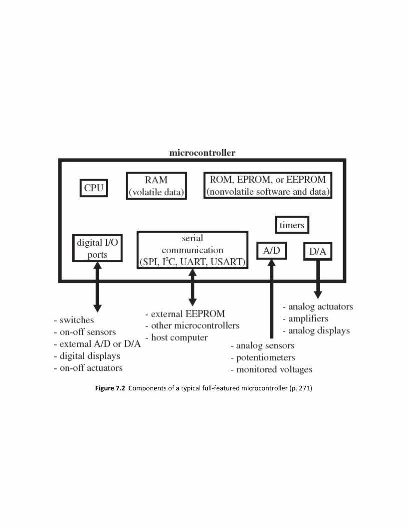
Figure 7.2 Components of a typical full-featured microcontroller (p. 271)

Figure 7.4 PIC16F84 pin-out and required external components (p. 274)
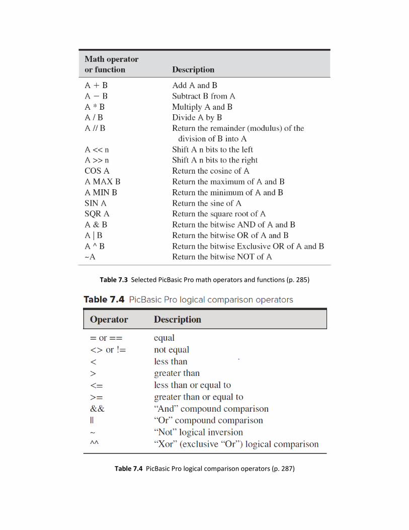
Table 7.3 Selected PicBasic Pro math operators and functions (p. 285)
Table 7.4 PicBasic Pro logical comparison operators (p. 287)
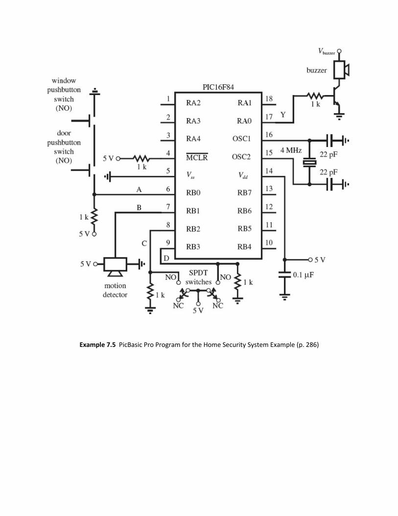
Example 7.5 PicBasic Pro Program for the Home Security System Example (p. 286)
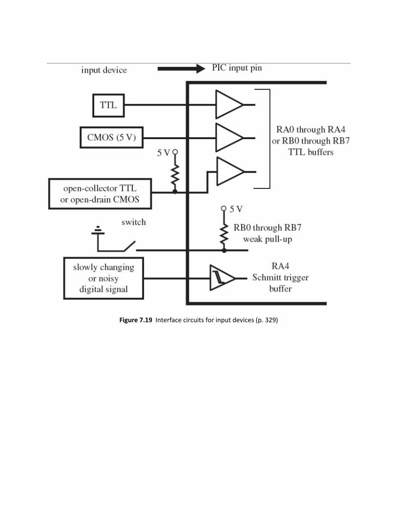
Figure 7.19 Interface circuits for input devices (p. 329)

Figure 7.20 Interface circuits for output devices (p. 330)
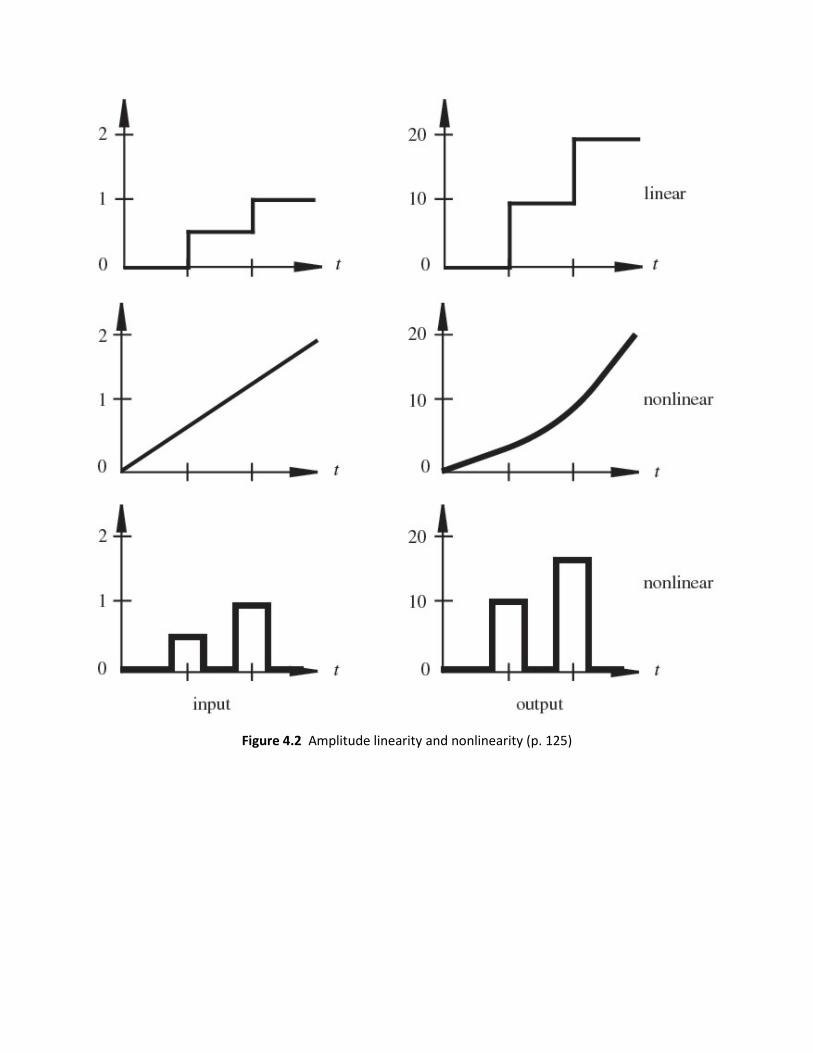
Figure 4.2 Amplitude linearity and nonlinearity (p. 125)

Section 4.3 FOURIER SERIES REPRESENTATION OF SIGNALS (pg. 126)

Figure 4.4 Harmonic decomposition of a square wave (p. 128)
Figure 4.5 Spectrum of a square wave (p. 129)

Figure 4.6 Frequency response and bandwidth (p. 130)
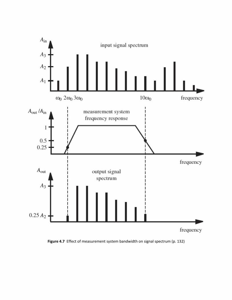
Figure 4.7 Effect of measurement system bandwidth on signal spectrum (p. 132)
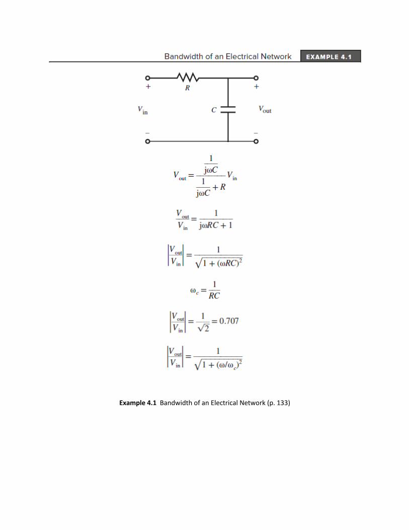
Example 4.1 Bandwidth of an Electrical Network (p. 133)
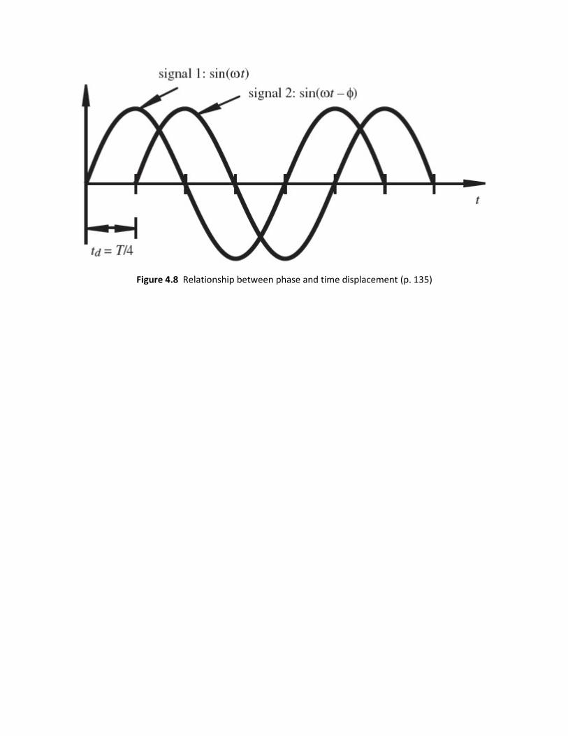
Figure 4.8 Relationship between phase and time displacement (p. 135)
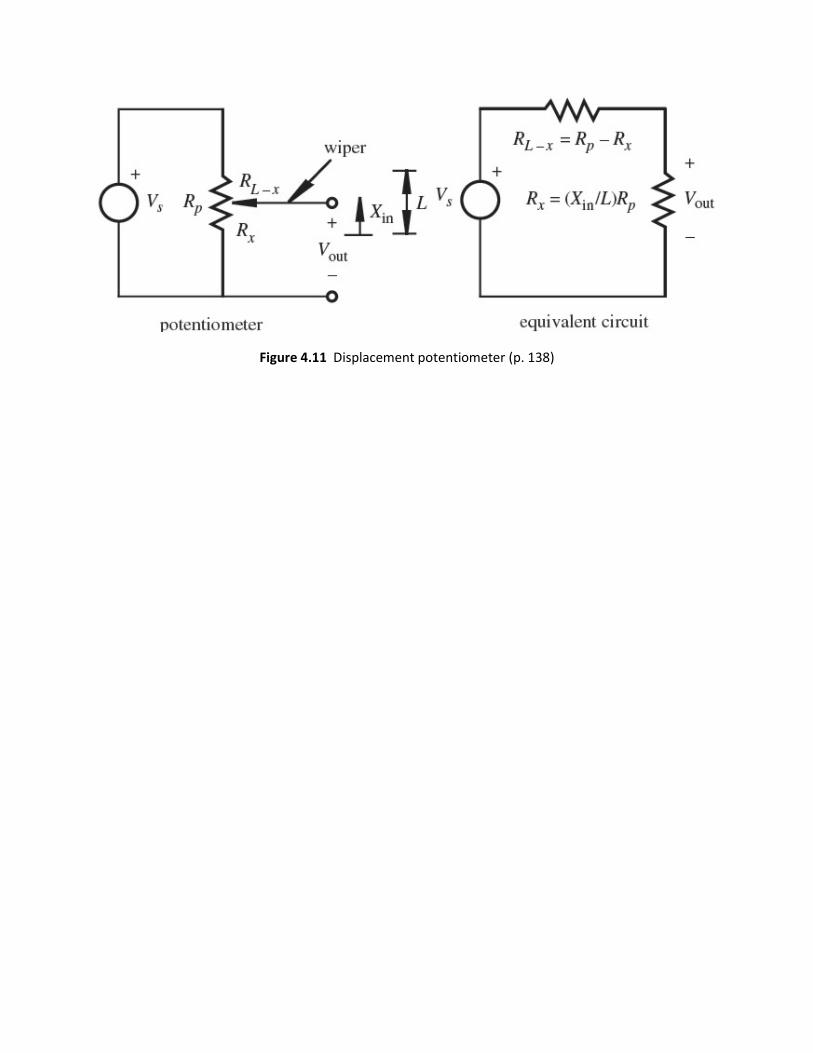
Figure 4.11 Displacement potentiometer (p. 138)

Figure 4.12 First-order response (p. 141)
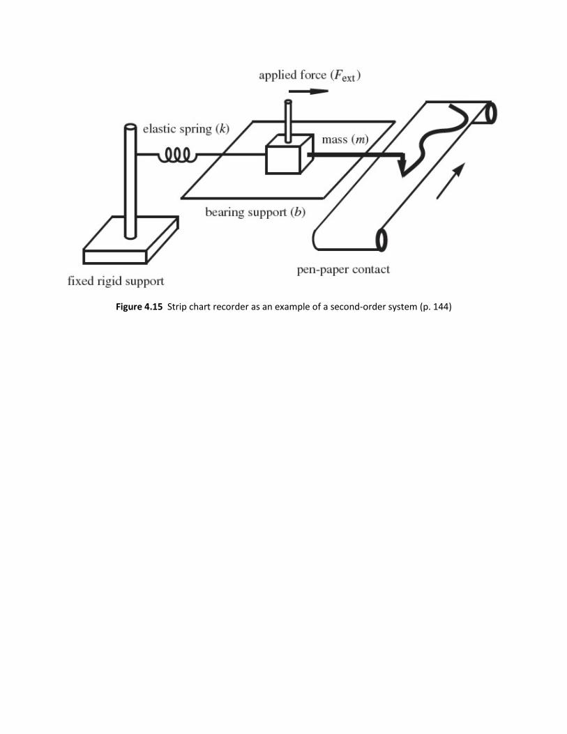
Figure 4.15 Strip chart recorder as an example of a second-order system (p. 144)
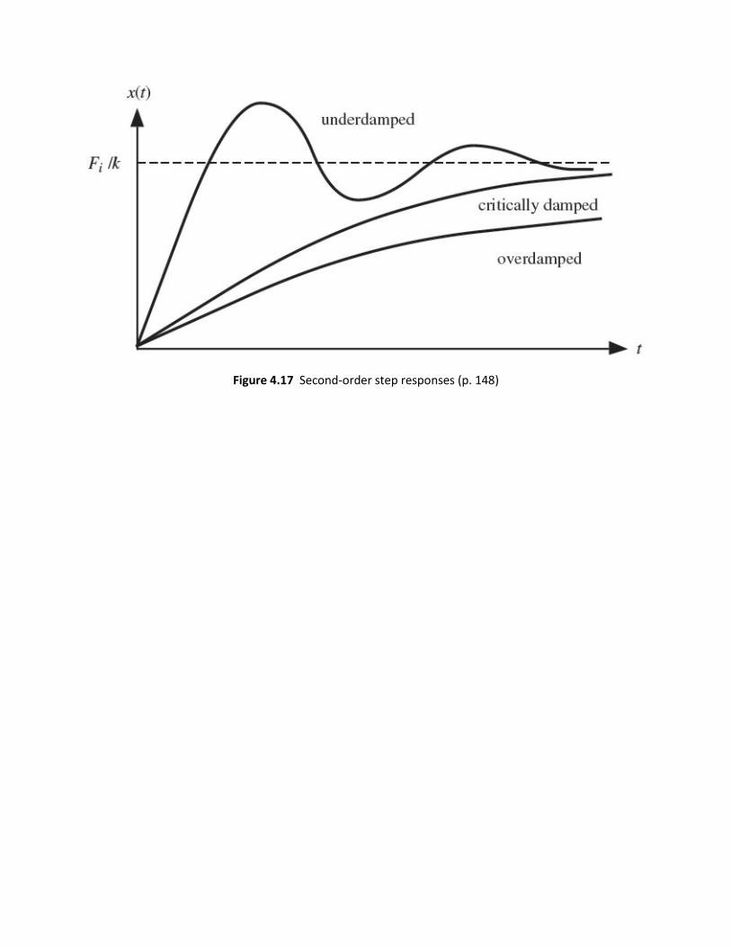
Figure 4.17 Second-order step responses (p. 148)

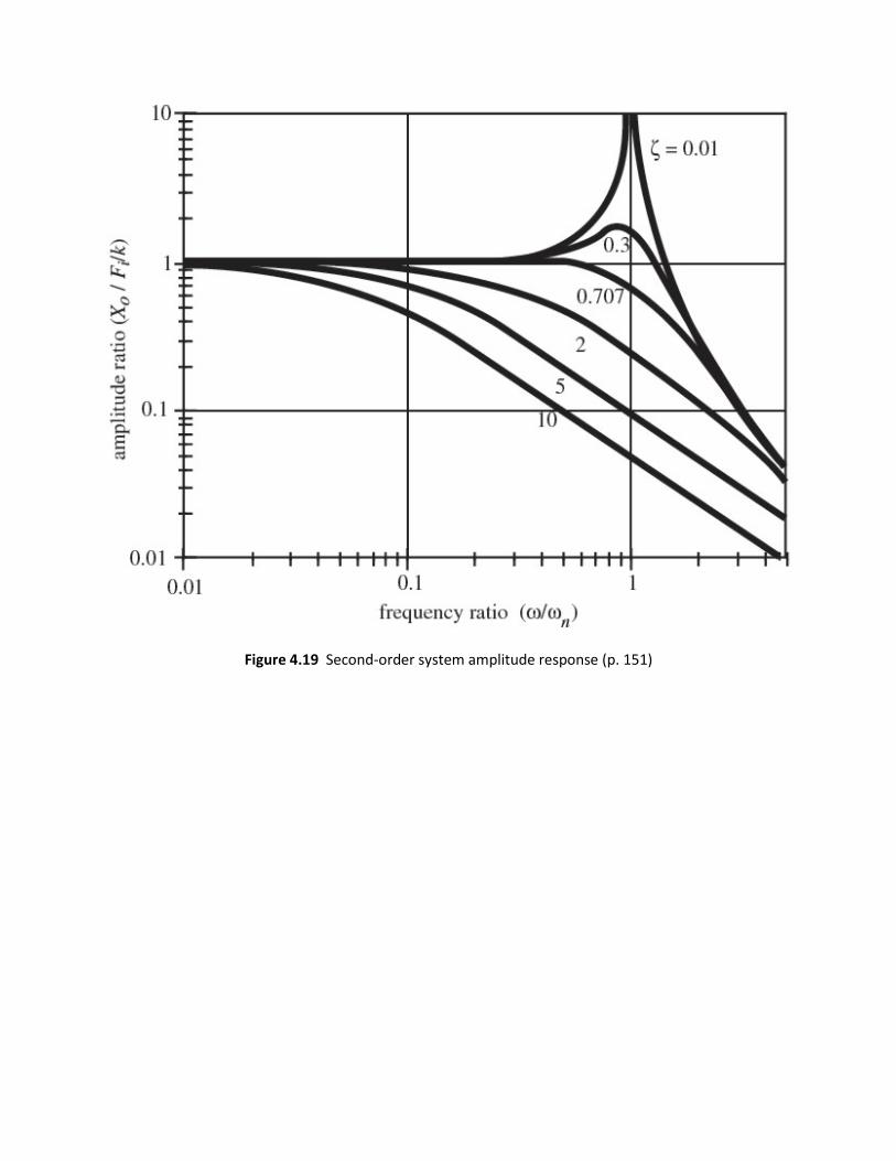
Figure 4.19 Second-order system amplitude response (p. 151)

Figure 4.20 Second-order system phase response (p. 152)
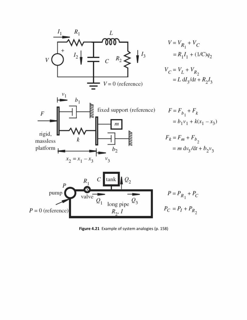
Figure 4.21 Example of system analogies (p. 158)
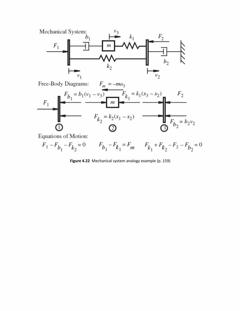
Figure 4.22 Mechanical system analogy example (p. 159)

Figure 5.2 Op amp terminology and schematic representation (p. 171)
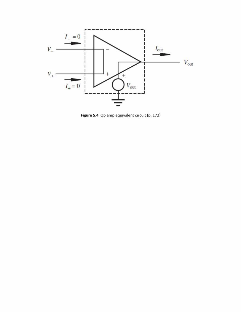
Figure 5.4 Op amp equivalent circuit (p. 172)
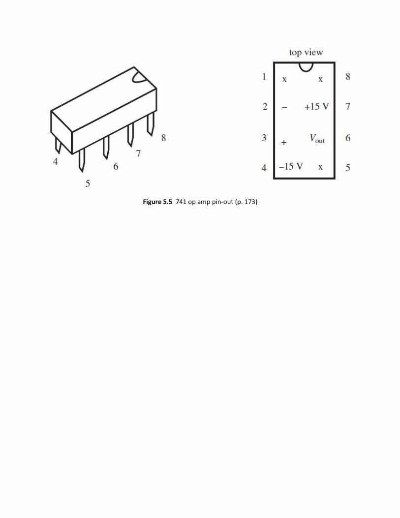
Figure 5.5 741 op amp pin-out (p. 173)

-
+
R C
++
Vout
iout
VoutVin
iin
RF
ideal model
Figure 5.8 Equivalent circuit for an inverting amplifier (p. 175)


Figure 5.11 Equivalent circuit for a noninverting amplifier (p. 177)

Figure 5.19 Ideal integrator (p. 185)

Figure 5.20 Improved integrator (p. 186)
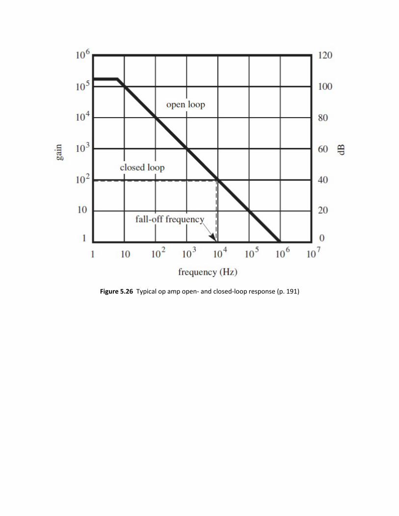
Figure 5.26 Typical op amp open- and closed-loop response (p. 191)

Example 5.1 Sizing Resistors in Op Amp Circuits (p. 195)
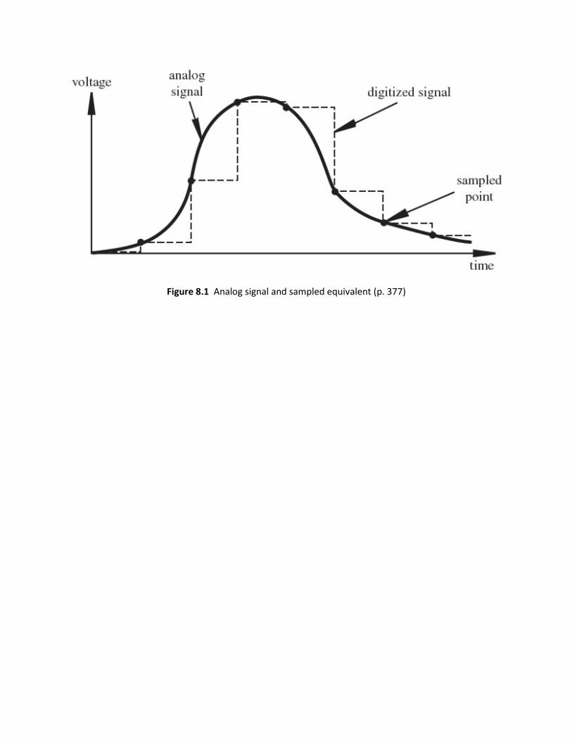
Figure 8.1 Analog signal and sampled equivalent (p. 377)
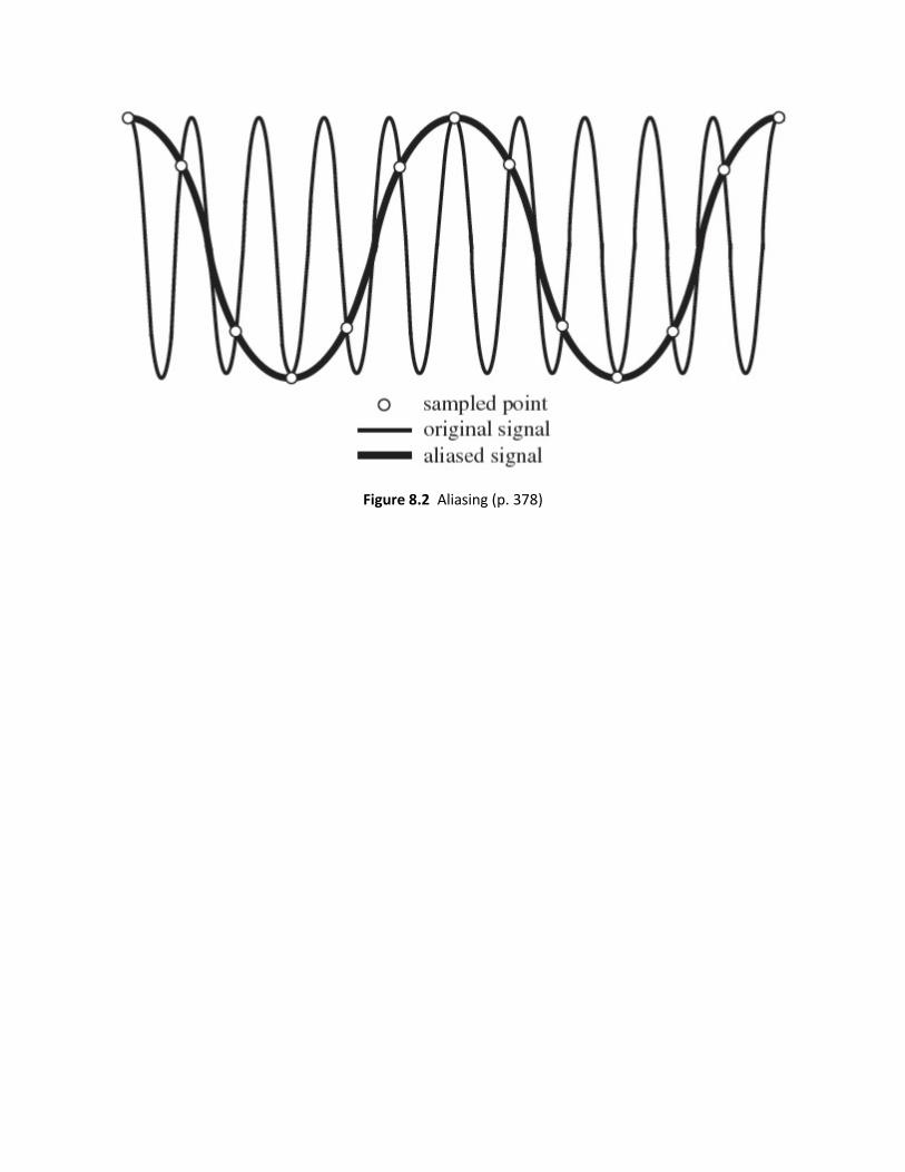
Figure 8.2 Aliasing (p. 378)

Example 8.1 Sampling Theorem and Aliasing (p. 379)
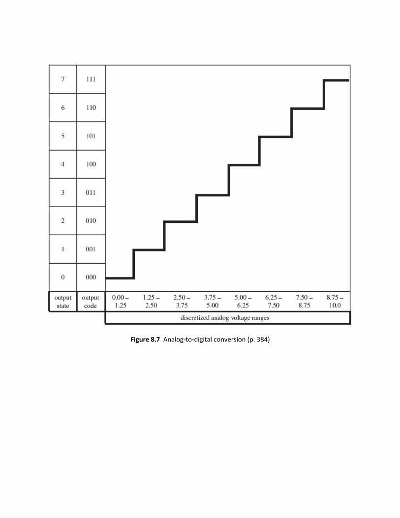
Figure 8.7 Analog-to-digital conversion (p. 384)
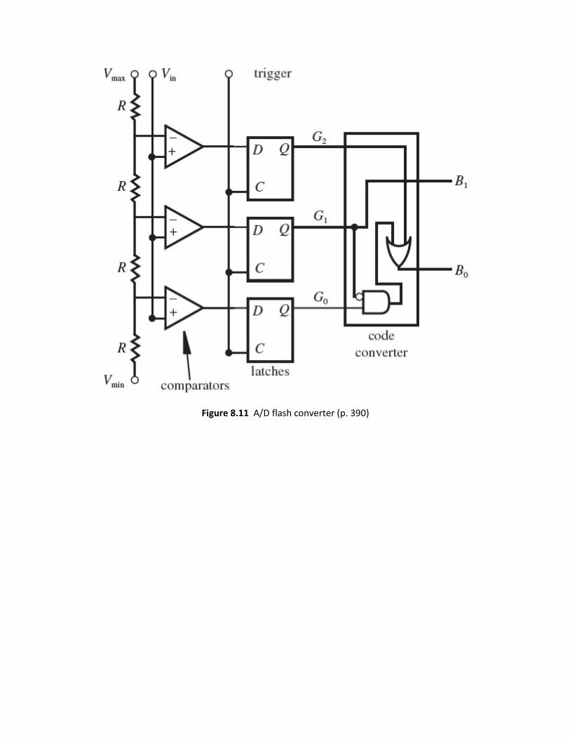
Figure 8.11 A/D flash converter (p. 390)

Figure 2.49 Inductive coupling (p. 62)
Figure 2.50 Ground loop (p. 63)
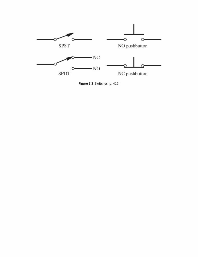
Figure 9.2 Switches (p. 412)
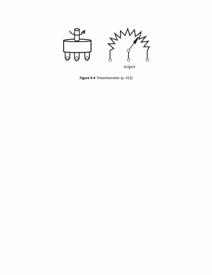
Figure 9.4 Potentiometer (p. 413)
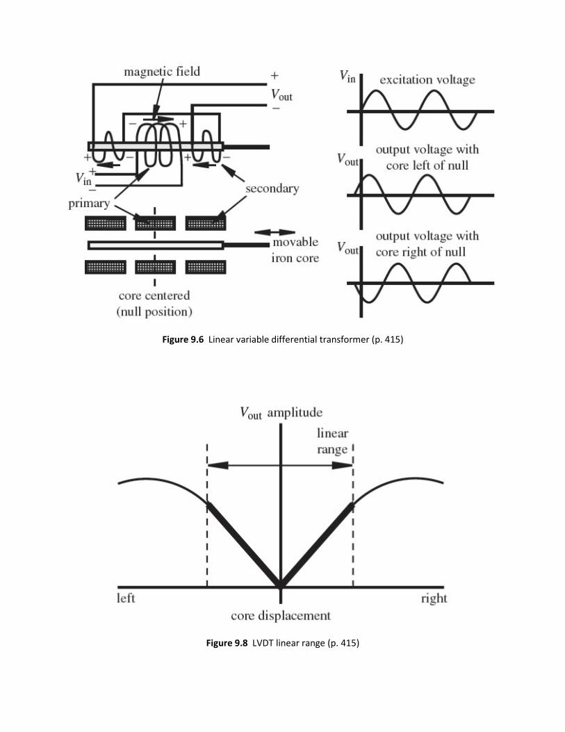
Figure 9.6 Linear variable differential transformer (p. 415)
Figure 9.8 LVDT linear range (p. 415)

Figure 9.9 LVDT demodulation (p. 415)
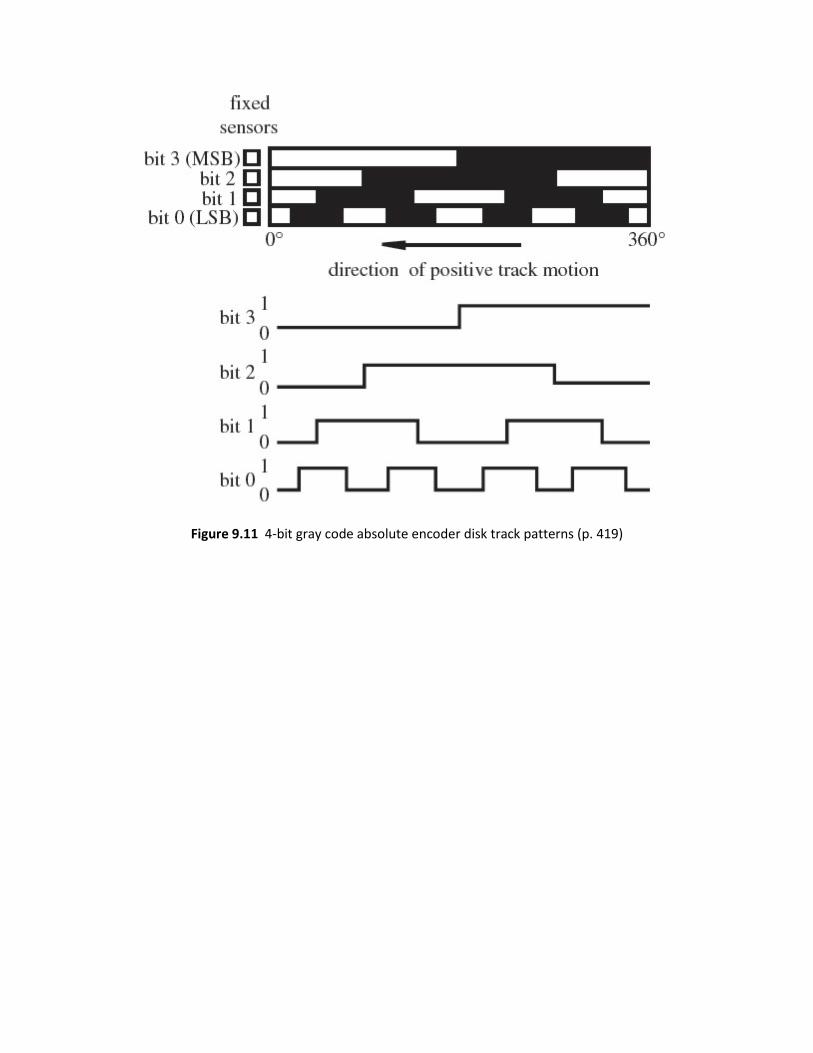
Figure 9.11 4-bit gray code absolute encoder disk track patterns (p. 419)

Figure 9.12 4-bit natural binary absolute encoder disk track patterns (p. 419)
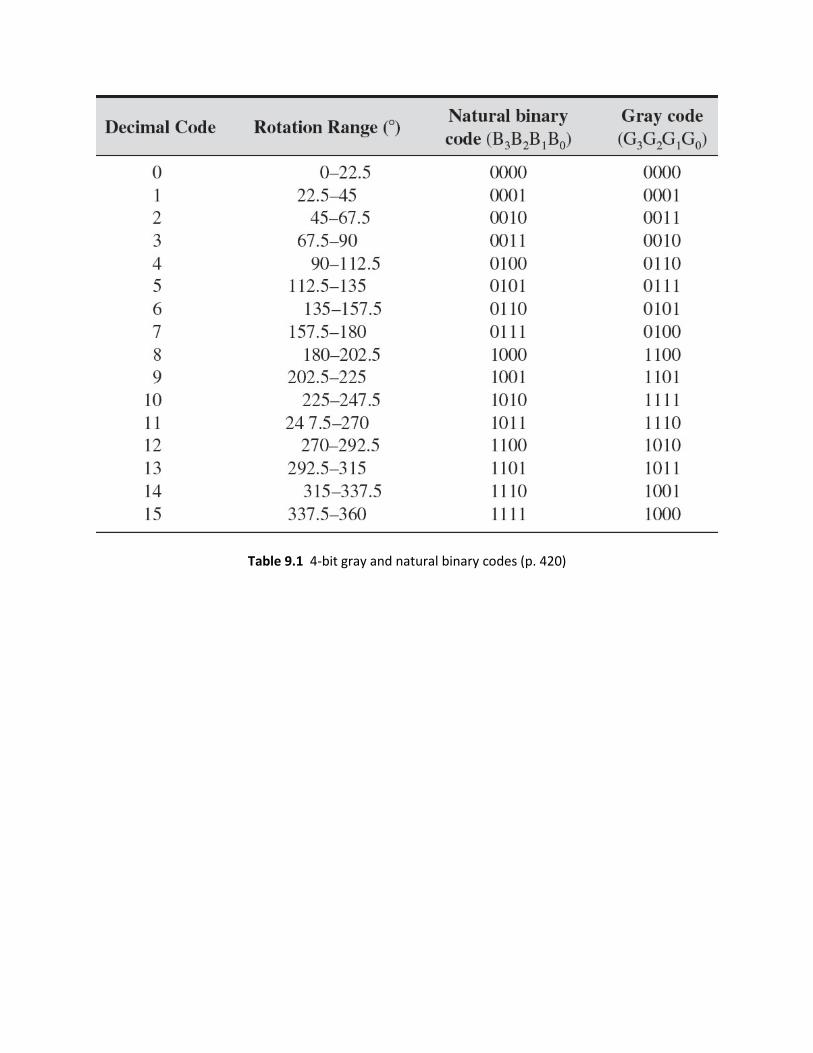
Table 9.1 4-bit gray and natural binary codes (p. 420)
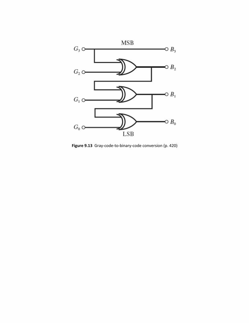
Figure 9.13 Gray-code-to-binary-code conversion (p. 420)
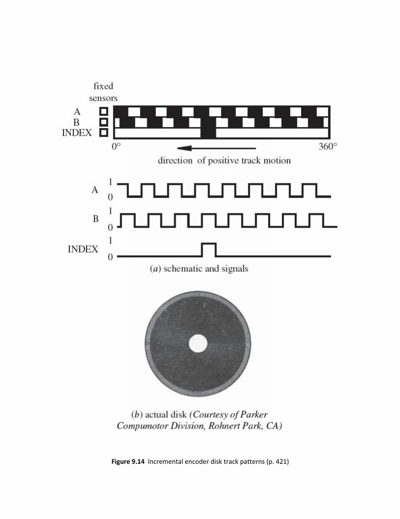
Figure 9.14 Incremental encoder disk track patterns (p. 421)
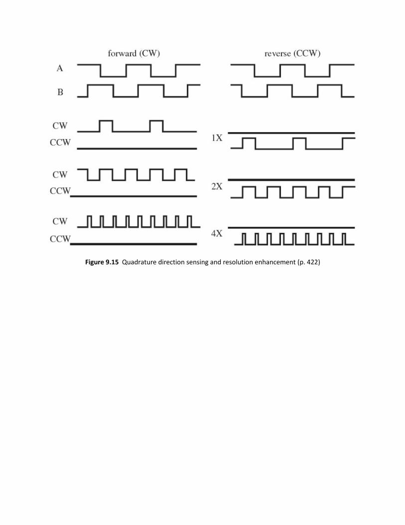
Figure 9.15 Quadrature direction sensing and resolution enhancement (p. 422)

Figure 9.16 1X quadrature decoder circuit (p. 423)
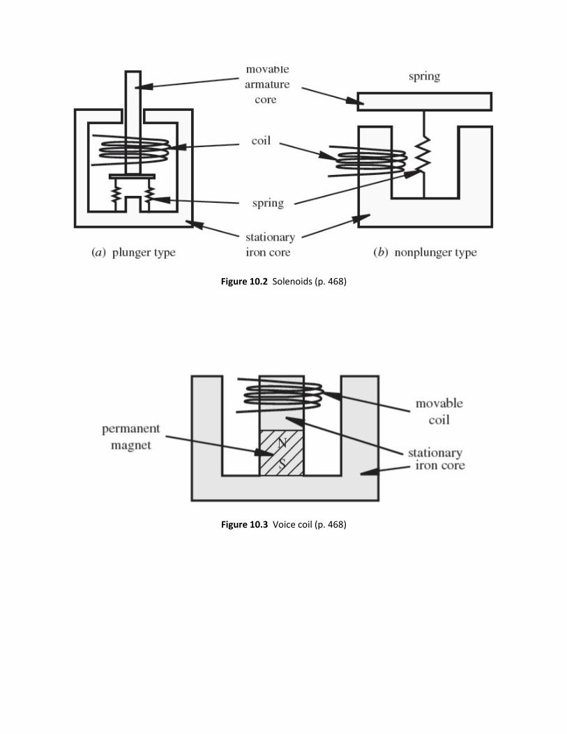
Figure 10.2 Solenoids (p. 468)
Figure 10.3 Voice coil (p. 468)

Figure 10.6 Motor construction and terminology (p. 470)
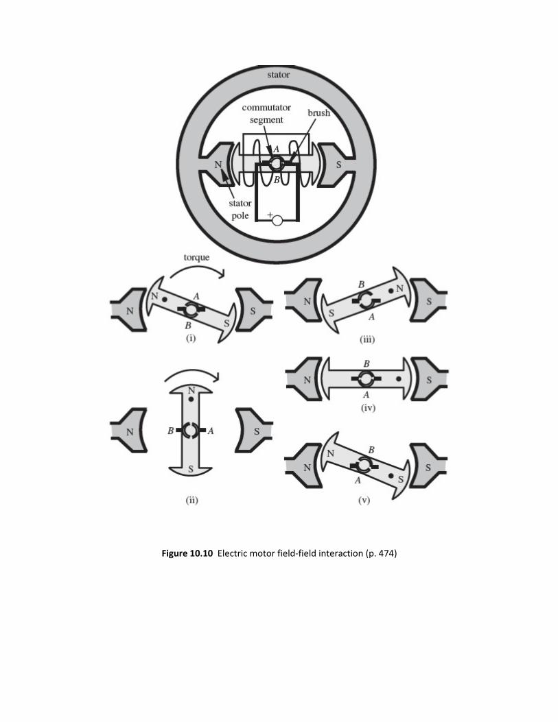
Figure 10.10 Electric motor field-field interaction (p. 474)

Figure 10.8 Electric motor field-current interaction (p. 472)
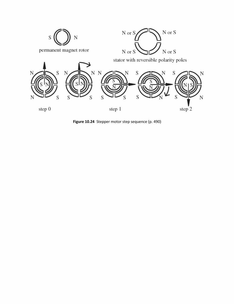
Figure 10.24 Stepper motor step sequence (p. 490)
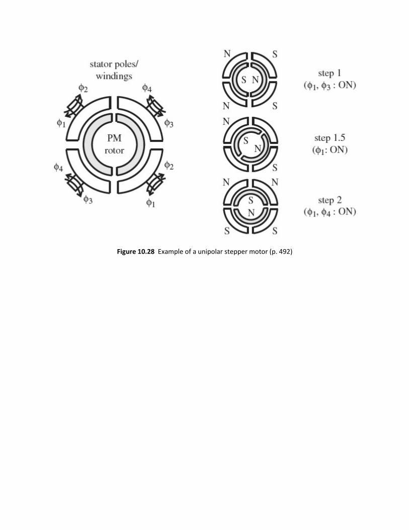
Figure 10.28 Example of a unipolar stepper motor (p. 492)
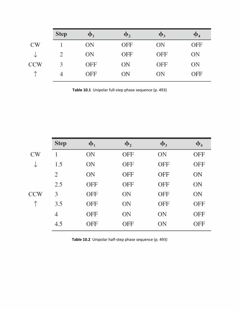
Table 10.1 Unipolar full-step phase sequence (p. 493)
Table 10.2 Unipolar half-step phase sequence (p. 493)
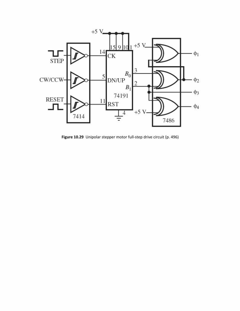
Figure 10.29 Unipolar stepper motor full-step drive circuit (p. 496)
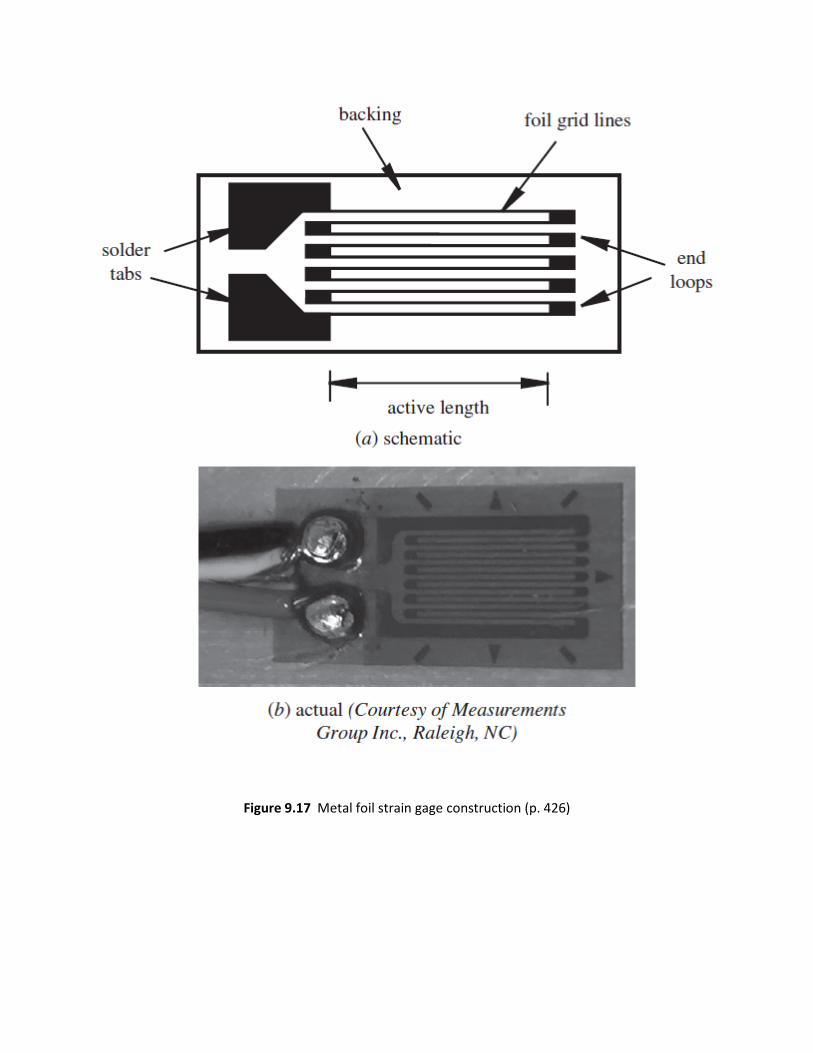
Figure 9.17 Metal foil strain gage construction (p. 426)

Figure 9.18 Rectangular conductor (p. 427)
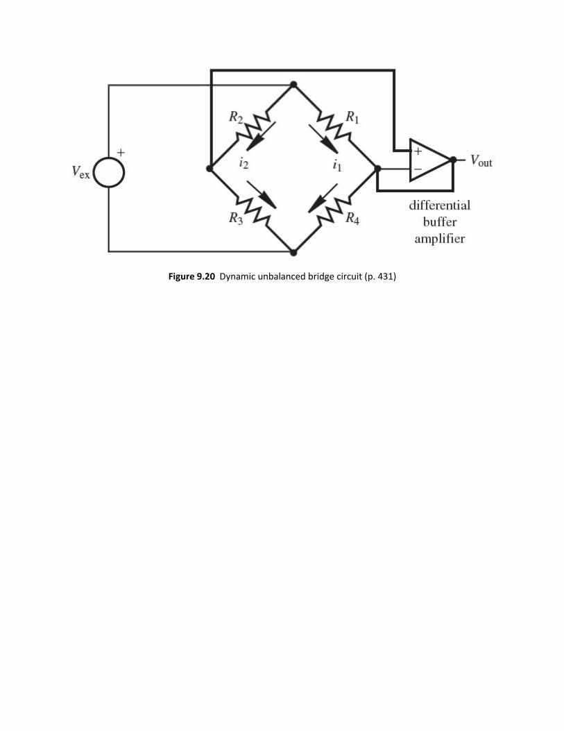
Figure 9.20 Dynamic unbalanced bridge circuit (p. 431)
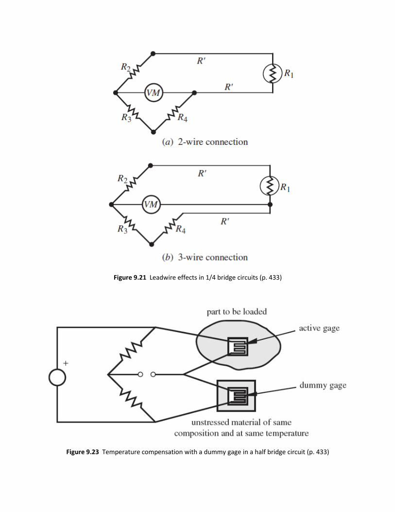
Figure 9.21 Leadwire effects in 1/4 bridge circuits (p. 433)
Figure 9.23 Temperature compensation with a dummy gage in a half bridge circuit (p. 433)
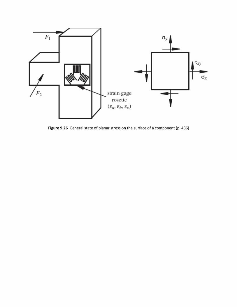
Figure 9.26 General state of planar stress on the surface of a component (p. 436)
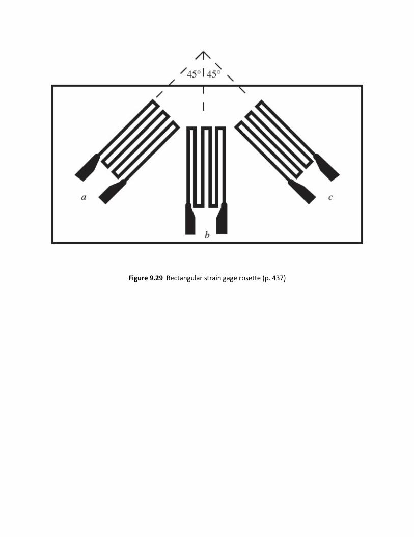
Figure 9.29 Rectangular strain gage rosette (p. 437)

Figure 9.44 Accelerometer displacement references and free-body diagram (p. 451)
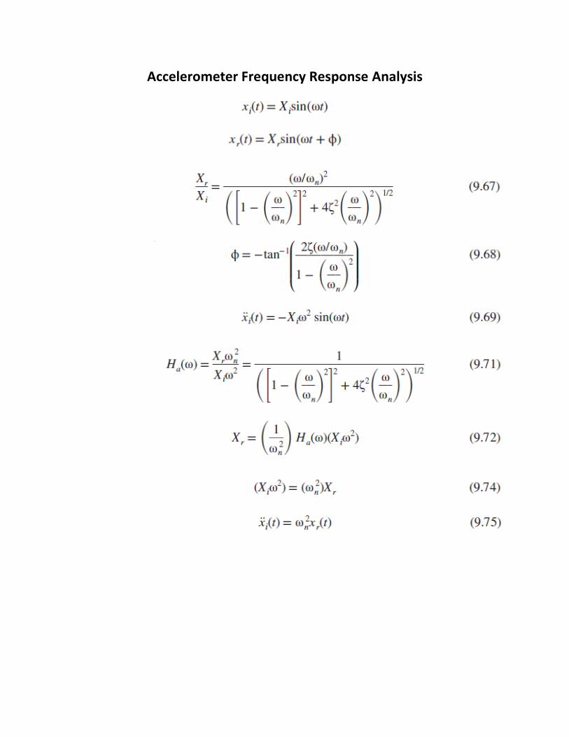
Accelerometer Frequency Response Analysis
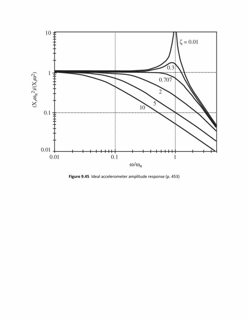
Figure 9.45 Ideal accelerometer amplitude response (p. 453)

Figure 9.48 Ideal accelerometer phase response (p. 454)
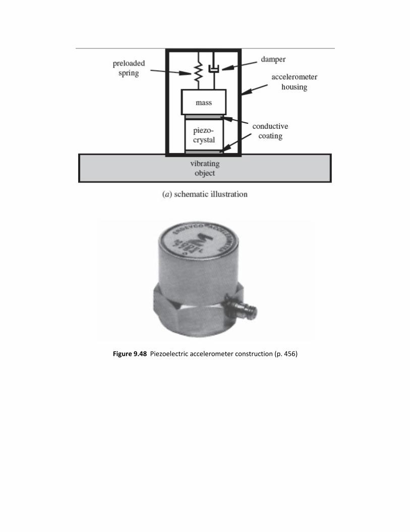
Figure 9.48 Piezoelectric accelerometer construction (p. 456)

Figure 9.51 Piezoelectric accelerometer frequency response (p. 458)
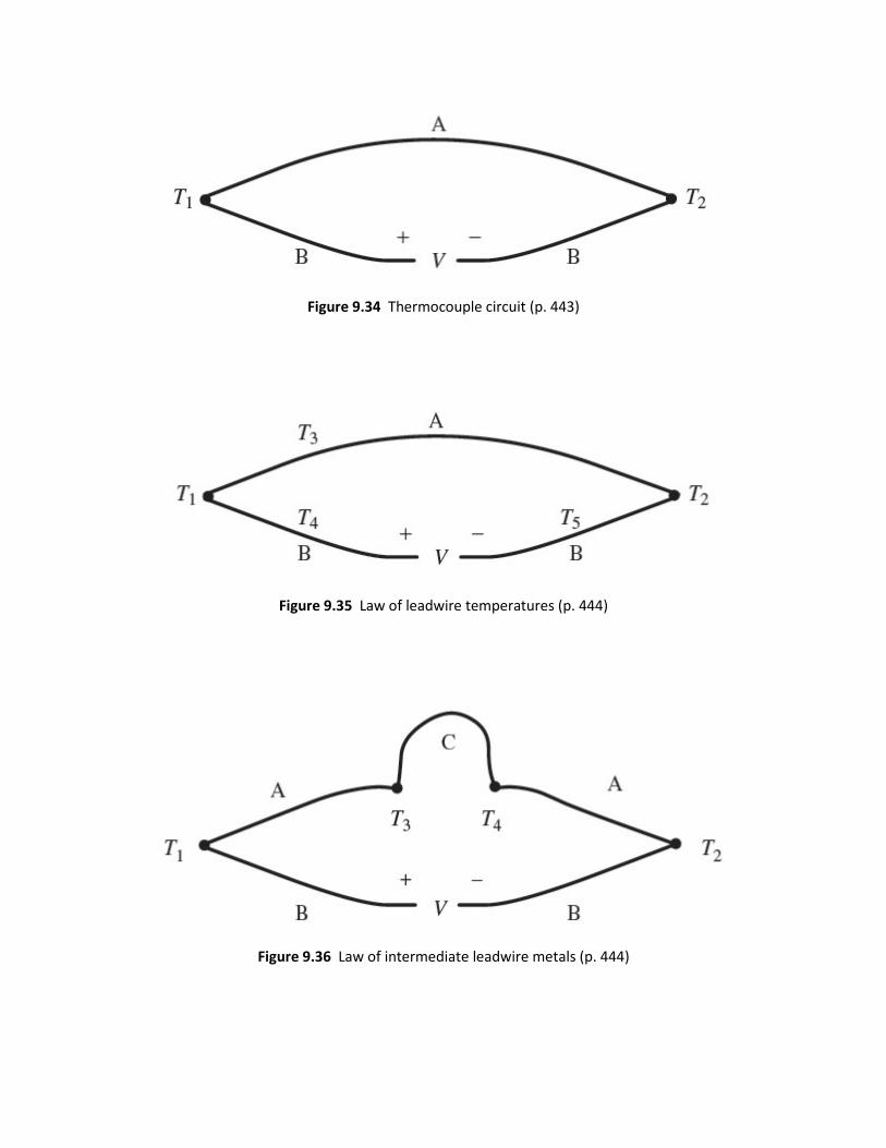
Figure 9.34 Thermocouple circuit (p. 443)
Figure 9.35 Law of leadwire temperatures (p. 444)
Figure 9.36 Law of intermediate leadwire metals (p. 444)

Figure 9.37 Law of intermediate junction metals (p. 445)
Figure 9.38 Law of intermediate temperatures (p. 445)
Figure 9.39 Law of intermediate metals (p. 446)
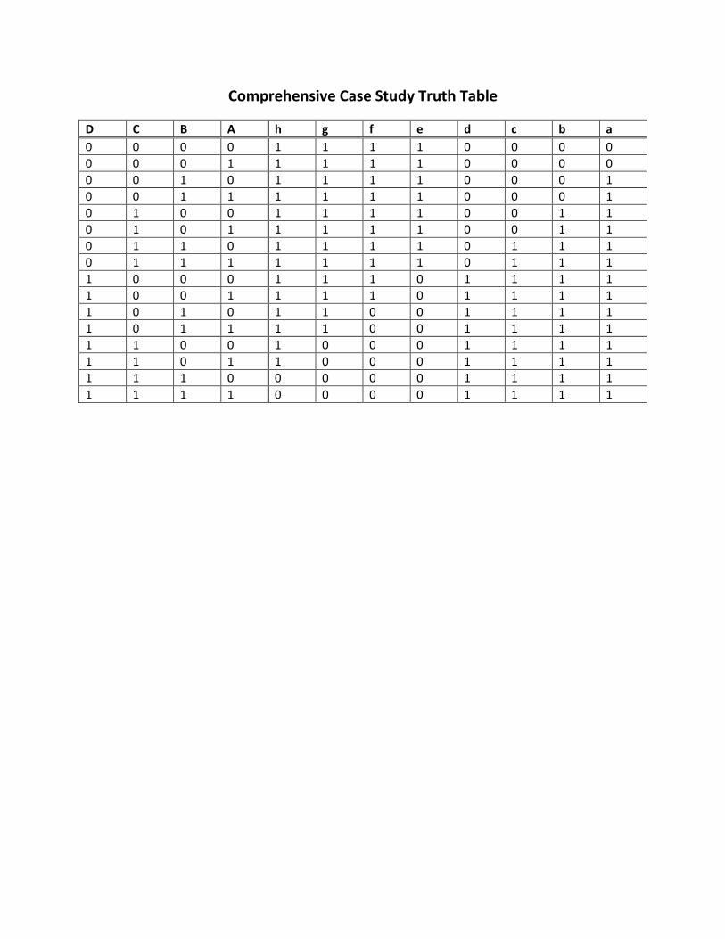
Comprehensive Case Study Truth Table
D C B A h g f e d c b a 0 0 0 0 1 1 1 1 0 0 0 0 0 0 0 1 1 1 1 1 0 0 0 0 0 0 1 0 1 1 1 1 0 0 0 1 0 0 1 1 1 1 1 1 0 0 0 1 0 1 0 0 1 1 1 1 0 0 1 1 0 1 0 1 1 1 1 1 0 0 1 1 0 1 1 0 1 1 1 1 0 1 1 1 0 1 1 1 1 1 1 1 0 1 1 1 1 0 0 0 1 1 1 0 1 1 1 1 1 0 0 1 1 1 1 0 1 1 1 1 1 0 1 0 1 1 0 0 1 1 1 1 1 0 1 1 1 1 0 0 1 1 1 1 1 1 0 0 1 0 0 0 1 1 1 1 1 1 0 1 1 0 0 0 1 1 1 1 1 1 1 0 0 0 0 0 1 1 1 1 1 1 1 1 0 0 0 0 1 1 1 1