Embed Size (px)
Citation preview

Unit 3-Networking and Communication (4hr) BIM IV/ II Compiled By : Er. Jeewan Rai
Client Server Computing [email protected] Page 1 of
11
3.1 Seven Layers Function of OSI Model 3.2 Cables (Structure, Application)
3.1.1 Guided (Twisted, Coaxial, Optical) 3.1.2 Unguided (Microwaves, Radiowaves, Bluetooth, WiMAX)
3.3 Concepts of Logical and Physical Topologies. 3.4 Effect of Bandwidth on Client/Server.
3.1 Seven Layers Function of OSI Model layers: each layer implements a service
via its own internal-layer actions
relying on services provided by layer below
ISO-OSI Model: There are many users who use computer network and
are located all over the world. To ensure national and
worldwide data communication ISO (ISO stands for
International Organization of Standardization.)
developed this model. This is called a model for open
system interconnection (OSI) and is normally called as OSI model. OSI model architecture consists of seven layers. It defines seven layers
or levels in a complete communication system.
Feature of OSI Model : 1. Big picture of communication over network is understandable through this OSI model. 2. We see how hardware and software work together. 3. We can understand new technologies as they are developed. 4. Troubleshooting is easier by separate networks. 5. Can be used to compare basic functional relationships on different networks. Protocol Data Unit (PDU) : In a layered system, a unit of data which is specified in a protocol of a given layer and which consists of protocol-control information and possibly user data of that layer. For example: Frame, Packets.
OSI Layers are 1.PHYSICAL LAYER The physical layer, the lowest layer of the OSI model, is concerned with the
transmission and reception of the unstructured raw bit stream over a
physical medium e.g Cable-Ethernet, Fibre. It describes the
electrical/optical, mechanical, and functional interfaces to the physical
medium, and carries the signals for all of the higher layers. It provides:
- Data encoding: modifies the simple digital signal pattern (1s and 0s) used by the PC to better accommodate the characteristics of the physical medium, and to aid in bit and frame synchronization. It determines:
- Transmission technique: determines whether the encoded bits will be transmitted by baseband (digital) or broadband (analog) signaling.
- Physical medium transmission: transmits bits as electrical or optical signals appropriate for the physical medium, and determines: - What physical medium options can be used and How many volts/db should be used to represent a given signal state, using a given
physical medium 2.DATA LINK LAYER
The data link layer provides error-free transfer of data frames from one node to another over the physical layer, allowing layers above it
to assume virtually error-free transmission over the link. operations package and unpack the data in frames. To do this, the data link
layer provides:
- Link establishment and termination: establishes and terminates the logical link between two nodes.
Fig. OSI 7 Layers
Data
PDU
Fig. Layering of airline functionality
TCP-Segment/
UDP-Datagram
PDU
Data
Data
Data
Packet
Frame
Bits
Sender Receiver
Unit 3-Networking and Communication (4hr) BIM IV/ II Compiled By : Er. Jeewan Rai
Client Server Computing [email protected] Page 2 of
11
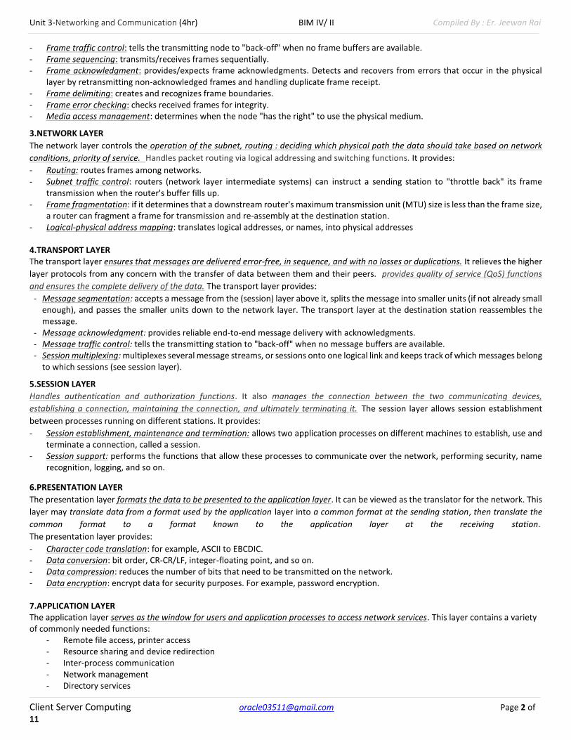
- Frame traffic control: tells the transmitting node to "back-off" when no frame buffers are available. - Frame sequencing: transmits/receives frames sequentially. - Frame acknowledgment: provides/expects frame acknowledgments. Detects and recovers from errors that occur in the physical
layer by retransmitting non-acknowledged frames and handling duplicate frame receipt. - Frame delimiting: creates and recognizes frame boundaries. - Frame error checking: checks received frames for integrity. - Media access management: determines when the node "has the right" to use the physical medium.
3.NETWORK LAYER
The network layer controls the operation of the subnet, routing : deciding which physical path the data should take based on network
conditions, priority of service. Handles packet routing via logical addressing and switching functions. It provides:
- Routing: routes frames among networks. - Subnet traffic control: routers (network layer intermediate systems) can instruct a sending station to "throttle back" its frame
transmission when the router's buffer fills up. - Frame fragmentation: if it determines that a downstream router's maximum transmission unit (MTU) size is less than the frame size,
a router can fragment a frame for transmission and re-assembly at the destination station. - Logical-physical address mapping: translates logical addresses, or names, into physical addresses 4.TRANSPORT LAYER The transport layer ensures that messages are delivered error-free, in sequence, and with no losses or duplications. It relieves the higher
layer protocols from any concern with the transfer of data between them and their peers. provides quality of service (QoS) functions
and ensures the complete delivery of the data. The transport layer provides:
- Message segmentation: accepts a message from the (session) layer above it, splits the message into smaller units (if not already small enough), and passes the smaller units down to the network layer. The transport layer at the destination station reassembles the message.
- Message acknowledgment: provides reliable end-to-end message delivery with acknowledgments. - Message traffic control: tells the transmitting station to "back-off" when no message buffers are available. - Session multiplexing: multiplexes several message streams, or sessions onto one logical link and keeps track of which messages belong
to which sessions (see session layer).
5.SESSION LAYER
Handles authentication and authorization functions. It also manages the connection between the two communicating devices,
establishing a connection, maintaining the connection, and ultimately terminating it. The session layer allows session establishment
between processes running on different stations. It provides:
- Session establishment, maintenance and termination: allows two application processes on different machines to establish, use and terminate a connection, called a session.
- Session support: performs the functions that allow these processes to communicate over the network, performing security, name recognition, logging, and so on.
6.PRESENTATION LAYER
The presentation layer formats the data to be presented to the application layer. It can be viewed as the translator for the network. This
layer may translate data from a format used by the application layer into a common format at the sending station, then translate the
common format to a format known to the application layer at the receiving station.
The presentation layer provides:
- Character code translation: for example, ASCII to EBCDIC. - Data conversion: bit order, CR-CR/LF, integer-floating point, and so on. - Data compression: reduces the number of bits that need to be transmitted on the network. - Data encryption: encrypt data for security purposes. For example, password encryption. 7.APPLICATION LAYER The application layer serves as the window for users and application processes to access network services. This layer contains a variety of commonly needed functions:
- Remote file access, printer access - Resource sharing and device redirection - Inter-process communication - Network management - Directory services

Unit 3-Networking and Communication (4hr) BIM IV/ II Compiled By : Er. Jeewan Rai
Client Server Computing [email protected] Page 3 of
11
- Electronic messaging (such as mail) - Network virtual terminals
OSI Reference Model Example A web browser serves as a good practical illustration of the OSI model and the TCP/IP protocol suite: • The web browser serves as the user interface for accessing a website. The browser itself does not function at the Application layer. Instead, the web browser invokes the Hyper Text Transfer Protocol (HTTP) to interface with the remote web server, which is why http:// precedes every web address. • The Internet can provide data in a wide variety of formats, a function of the Presentation layer. Common formats on the Internet include HTML, XML, PHP, GIF, and JPEG. Any encryption or compression mechanisms used on a website are also considered a Presentation layer function. • The Session layer is responsible for establishing, maintaining, and terminating the session between devices, and determining whether the communication is half-duplex or full-duplex. However, the TCP/IP stack generally does not include session-layer protocols, and is reliant on lower-layer protocols to perform these functions. • HTTP utilizes the TCP Transport layer protocol to ensure the reliable delivery of data. TCP establishes and maintains a connection from the client to the web server, and packages the higher-layer data into segments. A sequence number is assigned to each segment so that data can be reassembled upon arrival. • The best path to route the data between the client and the web server is determined by IP, a Network layer protocol. IP is also responsible for the assigned logical addresses on the client and server, and for encapsulating segments into packets. • Data cannot be sent directly to a logical address. As packets travel from network to network, IP addresses are translated to hardware addresses, which are a function of the Data-Link layer. The packets are encapsulated into frames to be placed onto the physical medium. • The data is finally transferred onto the network medium at the Physical layer, in the form of raw bits. Signaling and encoding mechanisms are defined at this layer, as is the hardware that forms the physical connection between the client and the web server Think about how you access the Internet today. There are basically three different options:
Broadband access - In your home, you have either a DSL or cable modem. At the office, your company may be using a T1 or a T3 line.
WiFi access - In your home, you may have set up a WiFi router that lets you surf the Web while you lounge with your laptop. On the road, you can find WiFi hot spots in restaurants, hotels, coffee shops and libraries.
Dial-up access - If you are still using dial-up, chances are that either broadband access is not available, or you think that broadband access is too expensive.
3.2 Cables (Structure, Application) Despite advances in wireless technologies, many computer networks in the 21st century still rely on cables as a physical medium for devices to transfer data. Several standard types of network cables exist, each designed for specific purposes. 3.1.1 Guided (Twisted, Coaxial, Optical) Transmission medium is the means through which we send our data from one place to another. The first layer (physical layer) of Communication Networks OSI Seven-layer model is dedicated to the transmission media, we will study the OSI Model later. Factors to be considered while choosing Transmission Medium
I. Transmission Rate II. Cost and Ease of Installation
III. Resistance to Environmental Conditions IV. Distances
Bounded/Guided Transmission Media It is the transmission media in which signals are transmitted to a specific path using wire or cable. The types of Bounded/ Guided are discussed below. *Twisted Pair Cable A type of cable that consists of two independently insulated wires twisted around one another. The use of two wires twisted together helps to reduce crosstalk and electromagnetic induction. While twisted-pair cable is used by older telephone networks and is the least expensive type of local-area network (LAN) cable, most networks contain some twisted-pair cabling at some point along the network. Twisted Pair is of two types :
Unshielded Twisted Pair (UTP)
Shielded Twisted Pair (STP)

Unit 3-Networking and Communication (4hr) BIM IV/ II Compiled By : Er. Jeewan Rai
Client Server Computing [email protected] Page 4 of
11
*Unshielded Twisted Pair Cable : It is the most common type of telecommunication when compared with Shielded Twisted Pair Cable which consists of two conductors usually copper, each with its own colour plastic insulator. Identification is the reason behind coloured plastic insulation. UTP cables consist of 2 or 4 pairs of twisted cable. Cable with 2 pair use RJ-11 connector and 4 pair cable useRJ-45 connector. Advantages :
Installation is easy
Flexible
Cheap
It has high speed capacity,
100 meter limit
Higher grades of UTP are used in LAN technologies like Ethernet. It consists of two insulating copper wires (1mm thick). The wires are twisted together in a helical form to reduce electrical interference from similar pair. Disadvantages :
Bandwidth is low when compared with Coaxial Cable
Provides less protection from interference. *Shielded Twisted Pair Cable : This cable has a metal foil or braided-mesh covering which covers each pair of insulated conductors. Electromagnetic noise penetration is prevented by metal casing. Shielding also eliminates crosstalk. It has same attenuation as unshielded twisted pair. It is faster the unshielded and coaxial cable. It is more expensive than coaxial and unshielded twisted pair. Advantages :
Easy to install
Performance is adequate
Can be used for Analog or Digital transmission
Increases the signaling rate
Higher capacity than unshielded twisted pair
Eliminates crosstalk Disadvantages :
Difficult to manufacture
Heavy *Coaxial Cable Coaxial is called by this name because it contains two conductors that are parallel to each other. Copper is used in this as center conductor which can be a solid wire or a standard one. It is surrounded by PVC installation, a sheath which is covered in an outer conductor of metal foil, braid or both. Outer metallic wrapping is used as a shield against noise and as the second conductor which completes the circuit. The outer conductor is also encased in an insulating sheath. The outermost part is the plastic cover which protects the whole cable. There are two types of Coaxial cables : (i)BaseBand : This is a 50 ohm (Ω) coaxial cable which is used for digital transmission. It is mostly used for LAN’s. Baseband transmits a single signal at a time with very high speed. The major drawback is that it needs amplification after every 1000 feet. (ii)BroadBand : This uses analog transmission on standard cable television cabling. It transmits several simultaneous signal using different frequencies. It covers large area when compared with Baseband Coaxial Cable. Advantages :
Bandwidth is high
Fig.:- Coaxial Cable

Unit 3-Networking and Communication (4hr) BIM IV/ II Compiled By : Er. Jeewan Rai
Client Server Computing [email protected] Page 5 of
11
Used in long distance telephone lines.
Transmits digital signals at a very high rate of 10Mbps.
Much higher noise immunity
Data transmission without distortion.
The can span to longer distance at higher speeds as they have better shielding when compared to twisted pair cable Disadvantages :
Single cable failure can fail the entire network.
Difficult to install and expensive when compared with twisted pair.
If the shield is imperfect, it can lead to grounded loop. *Fiber Optic Cable These are similar to coaxial cable. It uses electric signals to transmit data. At the centre is the glass core through which light propagates. In multimode fibres, the core is 50microns, and In single mode fibres, the thickness is 8 to 10 microns. The core in fiber optic cable is surrounded by glass cladding with lower index of refraction as compared to core to keep all the light in core. This is covered with a thin plastic jacket to protect the cladding. The fibers are grouped together in bundles protected by an outer shield. Fiber optic cable has bandwidth more than 2 gbps (Gigabytes per Second) Advantages :
Provides high quality transmission of signals at very high speed.
These are not affected by electromagnetic interference, so noise and distortion is very less.
Used for both analog and digital signals. Disadvantages :
It is expensive
Difficult to install.
Maintenance is expensive and difficult.
Do not allow complete routing of light signals. 3.1.2 Unguided (Microwaves, Radiowaves, Bluetooth, WiMAX) Unguided or wireless media sends the data through air (or water), which is available to anyone who has a device capable of receiving them. Types of unguided/ unbounded media are discussed below :
Radio Transmission
MicroWave Transmission *Radio Transmission Its frequency is between 10 kHz to 1GHz. It is simple to install and has high attenuation. These waves are used for multicast communications. Types of Propogation Radio Transmission utilizes different types of propagation :
Troposphere : The lowest portion of earth’s atmosphere extending outward approximately 30 miles from the earth’s surface. Clouds, jet planes, wind is found here.
Ionosphere : The layer of the atmosphere above troposphere, but below space. Contains electrically charged particles. The lowest
frequency radio waves are also reflected from an electrically charged layer of the upper atmosphere,
Fig. Fiber Optic Cable
Fig. Radio Transmission

Unit 3-Networking and Communication (4hr) BIM IV/ II Compiled By : Er. Jeewan Rai
Client Server Computing [email protected] Page 6 of
11
*Microwave Transmission It travels at high frequency than the radio waves. It requires the sender to be inside of the receiver. It operates in a system with a low gigahertz range. It is mostly used for unicast communication. There are 2 types of Microwave Transmission : 1. Terrestrial Microwave 2. Satellite Microwave Advantages of Microwave Transmission
Used for long distance telephone communication
Carries 1000’s of voice channels at the same time Disadvantages of Microwave Transmission
It is Very costly Fig. Microwaves and radio waves in the atmosphere *WiMAX (Worldwide Interoperability for Microwave Access) WiMAX is a wireless industry union dedicated to the advancement of IEEE 802.16 standards for broadband wireless access (BWA) networks. WiMAX supports mobile, nomadic and fixed wireless applications. A mobile user, in this context, is someone in transit, such as a commuter on a train. A nomadic user is one that connects on a portable device but does so only while stationary -- for example, connecting to an office network from a hotel room and then again from a coffee shop. Fixed wireless typically refers to wireless connectivity among non-mobile devices in homes or businesses. WiMAX serves a larger inter-operable network. WiMAX can be used to provide internet services to a larger area where it can serve households, mobile phones and even Wi-Fi spots. WiMAX has a different hardware specification and currently WiMAX serving towers tend to be as tall as Wi-Fi towers. On the other hand, Wi-Fi antennas are small enough to be placed on 5 inch by 3 inch routers.
WiMAX provide:
The high speed of broadband service
Wireless rather than wired access, so it would be a lot less expensive than cable or DSL and much easier to extend to suburban and rural areas
Broad coverage like the cell phone network instead of small Wi-Fi hotspots
Wi-Fi V/S WiMAX -Range: An ideal Wi-Fi based network reaches around 100metres as it maximum range whereas an ideal WiMAX network can reach about 80-90kilometers in terms of range. -Data Transfer Rates: Wi-Fi based networking can transfer data at speeds up to 54mbps. On the other hand, WiMAX networks exchange data at speeds upto 40mbps. In WiMAX, data transfer rates have more variation as distances to be covered are quite larger. -Channel Bandwidth: Wi-Fi networks have a channel bandwidth of 20MHz, whereas WiMAX networks have a flexible bandwidth option which ranges from 1.25MHz to 20MHz. -Bandwidth Efficiency: This term refers to bits of information sent per second per unit frequency. This is a measure of how qualitatively the channel is managed by the network. Bandwidth efficiency of a WiMAX channel (upto 5bps/s/Hz) is theoretically twice as efficient as Wi-Fi based networks (upto 0.44bps/s/Hz for 802.11a and 2.7bps/s/Hz for b/g/n standards). -Applications: Wi-Fi and WiMAX, though being used for same purpose of data exchange, are designed to cater two completely different needs. Wi-Fi is needed to serve for household and corporate needs of interconnectivity. Wi-Fi technology connects printers to computer, gaming consoles to router etc.
Fig. Microwave Transmission
Fig. WiMAX

Unit 3-Networking and Communication (4hr) BIM IV/ II Compiled By : Er. Jeewan Rai
Client Server Computing [email protected] Page 7 of
11
*Bluetooth
Bluetooth is a wireless technology standard for exchanging data over short distances (using short-wavelength UHF radio waves in the ISM band from 2.4 to 2.485 GHz) from fixed and mobile devices, and building personal area networks (PANs). Invented by telecom vendor Ericsson in 1994, it was originally conceived as a wireless alternative to RS-232 data cables. Any Bluetooth device in discoverable mode transmits the following information on demand:
Device name and Device class
List of services
Technical information (for example: device features, manufacturer, Bluetooth specification used, clock offset)
Every device has a unique 48-bit address. However, these addresses are generally not shown in inquiries. Instead, friendly Bluetooth names are used, which can be set by the user. This name appears when another user scans for devices and in lists of paired devices. Most cellular phones have the Bluetooth name set to the manufacturer and model of the phone by default. Most cellular phones and laptops show only the Bluetooth names and special programs are required to get additional information about remote devices. 3.3 Concepts of Logical and Physical Topologies. People often draw diagrams or pictures to help describe complicated things. Maps are pictures of routes to get from point A to point B. When we use the word 'topology' in this lesson, we are referring to how things in a network are connected, as in a configuration.
A physical topology describes how network devices are physically connected - how devices are actually plugged into each other. We're talking about cables, wireless connectivity, etc. Types
- Bus, Ring, Mesh, Star
A logical topology describes how network devices appear to be connected to each other. Types
- Token Passing ( Token Ring, Token Bus, FDDI (Fiber Distributed Data Interface)) - Broadcast topology Token Passing Token is passed sequentially to each host. When a host receives the token, that host can send data on the network. If the host has no data to send, it passes the token to the next host and the process repeats itself. Token Ring Token ring is a LAN topology where nodes/stations are arranged in a ring topology. A node can only transmit when in possession of a sequence of bits (the token), which is passed to each node in turn. Token Bus Token Bus is a Local Area Network (LAN) in which the stations on the bus or tree form a logical ring. Each station is assigned a place in an ordered sequence, with the last station in the sequence being followed by the first, as shown below. Each station knows the address of the station to its "left" and "right" in the sequence. FDDI FDDI (Fiber Distributed Data Interface) is a set of ANSI and ISO standards for data transmission on fiber optic lines in a local area network (LAN) that can extend in range up to 200 km (124 miles). The FDDI protocol is based on the token ring protocol. Fiber Distributed Data Interface (FDDI) is an expensive technology to set up because the network devices require a special network card and also fiber-optic cabling is required, which is expensive than twisted-pair cable. Because most Fiber Distributed Data Interface (FDDI) installations use a redundant second ring, more cabling is required.
For example, in a logical diagram of your office network, you may show a connection between city A and city B. But in the actual physical network, maybe your data goes through switching points in several other cities as well. The logical path is a high-level representation; the physical path is the actual route.
A mobile phone mast - an example of a microwave
transmitter

Unit 3-Networking and Communication (4hr) BIM IV/ II Compiled By : Er. Jeewan Rai
Client Server Computing [email protected] Page 8 of
11
*Features of Hybrid Topology - It is a combination of two
or topologies - Inherits the advantages
and disadvantages of the topologies included
Advantages of Hybrid Topology - Reliable as Error
detecting and troubleshooting is easy. - Flexible and Effective. - Scalable as size can be
increased easily. Disadvantages of Hybrid Topology Costly and Complex in design.
*Features of Bus Topology - It transmits data only in one direction. - Every device is connected to a single cable Advantages of Bus Topology - It is easy to understand and cost effective. - Cable required is least compared to other network topology. - Used for small networks. - Easy to expand joining two cables together. Disadvantages of Bus Topology - Cables has a limited length and if cable fails then whole network
fails. - If network traffic is heavy or nodes are more the performance of
the network decreases. - It is slower than the ring topology. *Features of Star Topology - Every node has its own dedicated connection to the hub. - Hub acts as a repeater for data flow. - Can be used with twisted pair, Optical Fiber or coaxial cable. Advantages of Star Topology - Fast performance with few nodes and low network traffic. - Hub can be upgraded easily. - Easy to troubleshoot, setup and modify. - Only that node is affected which has failed, rest of the nodes can
work smoothly. Disadvantages of Star Topology - Cost of installation is high, Expensive to use. - If the hub fails then the whole network is stopped because all
the nodes depend on the hub. Performance is based on the hub that is it depends on its capacity *Features of Tree Topology - Ideal if workstations are located in groups. - Used in Wide Area Network. Advantages of Tree Topology - Extension of bus and star topologies. - Expansion of nodes is possible and easy. - Easily managed and maintained. - Error detection is easily done.
*Features of Ring Topology - A number of repeaters are used for Ring topology with large
number of nodes, because if someone wants to send some data to the last node in the ring topology with 100 nodes, then the data will have to pass through 99 nodes to reach the 100th node. Hence to prevent data loss repeaters are used in the network. - The transmission is unidirectional, but it can be made
bidirectional by having 2 connections between each Network Node, it is called Dual Ring Topology. - In Dual Ring Topology, two ring networks are formed, and data
flow is in opposite direction in them. Also, if one ring fails, the second ring can act as a backup, to keep the network up. - Data is transferred in a sequential manner that is bit by bit. Data
transmitted, has to pass through each node of the network, till the destination node.
Advantages of Ring Topology - Transmitting network is not affected by high traffic or by adding
more nodes, as only the nodes having tokens can transmit data. - Cheap to install and expand
Disadvantages of Ring Topology - Troubleshooting is difficult in ring topology. - Adding or deleting the computers disturbs the network activity.
Failure of one computer disturbs the whole network.
*Mesh Topology - Partial Mesh Topology : In this topology some of the systems are
connected in the same fashion as mesh topology but some devices are only connected to two or three devices. - Full Mesh Topology : Each and every nodes or devices are
connected to each other. Features of Mesh Topology - Fully connected. - Robust, Not flexible.
Advantages of Mesh Topology - Each connection can carry its own data load. - It is robust. - Fault is diagnosed easily.

Unit 3-Networking and Communication (4hr) BIM IV/ II Compiled By : Er. Jeewan Rai
Client Server Computing [email protected] Page 9 of
11
Disadvantages of Tree Topology - Costly and Heavily cabled. - If more nodes are added maintenance is difficult. Central hub fails, network fails.
- Provides security and privacy. Disadvantages of Mesh Topology - Installation and configuration is difficult. - Cabling cost is more. Bulk wiring is required.
Broadcast topology
FDDI Token Ring
Token Ring
Token Bus
3.4 Effect of Bandwidth on Client/ Server. When referring to a data connection, bandwidth, communication speed, or connection speed is the total maximum transfer rate of a network cable or device. Essentially, it is a measurement of how fast data can be sent over a wired or wireless connection, usually measure in bits per second. For example, when you connect to the Internet using a modem over a phone line, your operating system may display "Connected at 56 kbps" that indicates a maximum of 56 kilobits of data is transferred every second. The more bandwidth a computer has, the faster it will be able to send and receive information. Users with a broadband connection, more specifically fiber optic broadband, can get transfers speeds of up to 10 Gbps, which is nearly 180,000 times faster than a 56 kbps modem! Upload and download Most broadband connections are asynchronous, which means there are different speeds depending on the way data is traveling. A download speed or receiving speed is how fast your computer can get files from the Internet. The upload speed or sending speed is how fast your computer can send files to the Internet. Download speeds are nearly always faster than upload speeds with these connections.
- Slow Computing process - Performance degrade - Cost increases - Resources damage - Services delay -
1) In computer networks, bandwidth is used as a synonym for data transfer rate, the amount of data that can be carried from one point
to another in a given time period (usually a second). Network bandwidth is usually expressed in bits per second (bps, millions of bits per
second (megabits per second, or Mbps) or billions of bits per second (gigabits per second, or Gbps).
As network users' wants for bandwidth continues to skyrocket, SD-WAN promises to revolutionize the wide area network to deliver better connectivity, reduced complexity, and lower costs.

Unit 3-Networking and Communication (4hr) BIM IV/ II Compiled By : Er. Jeewan Rai
Client Server Computing [email protected] Page 10 of
11
Note that bandwidth is not the only factor that affects network performance: There is also packet loss, latency and jitter( is simply the difference in packet delay. In other words, jitter is measuring time difference in packet inter-arrival time.), all of which degrade network throughput and make a link perform like one with lower bandwidth. A network path usually consists of a succession of links, each with its own bandwidth, so the end-to-end bandwidth is limited to the bandwidth of the lowest speed link (the bottleneck).
Different applications require different bandwidths. An instant messaging conversation might take less than 1,000 bits per second (bps); a voice over IP (VoIP) conversation requires 56 kilobits per second (Kbps) to sound smooth and clear. Standard definition video (480p) works at 1 megabit per second (Mbps), but HD video (720p) wants around 4 Mbps, and HDX (1080p), more than 7 Mbps. Effective bandwidth -- the highest reliable transmission rate a path can provide -- is measured with a bandwidth test. This rate can be determined by repeatedly measuring the time required for a specific file to leave its point of origin and successfully download at its destination. 2) Bandwidth is the range of frequencies -- the difference between the highest-frequency signal component and the lowest-frequency signal component -- an electronic signal uses on a given transmission medium. Like the frequency of a signal, bandwidth is measured in hertz (cycles per second). This is the original meaning of bandwidth, although it is now used primarily in discussions about cellular networks and the spectrum of frequencies that operators license from various governments for use in mobile services. 3) In business, bandwidth is sometimes used as a synonym for capacity or ability. In this sense, bandwidth usually refers to having time or staffing available to tackle something, e.g. "We just don't have the bandwidth to take on mobile app development, we're already short-staffed on developers."
What is the importance of bandwidth? Bandwidth is highly significant for determining how fast a web page loads on a browser. In fact, it is also one of the essential things to consider while you’re choosing a platform for web hosting. The bandwidth can be significantly affected by the website and the internet connection used for accessing it. Generally, a website loaded with heavy graphics will need higher bandwidth of 10 gigs or more. Similarly, a simpler website will require comparatively lesser bandwidth. Just as fast internet connection allows you to download web pages and videos flawlessly, higher bandwidth will effectively improvise the user experience and let your users avail the very best from your website. - Bandwidth of a signal is a reference to how fast the signal is changing (around its center frequency), which again has to do with how
many samples of the signal you need to reconstruct it. If you have a sinusoid of a single frequency (just one sine wave), then all you need to represent the signal is two numbers, the value of the frequency and the height of the wave. It is sufficient to convey these two numbers precisely at the receiver to reconstruct this wave. This is why you have a impulse at that frequency in the Fourier transform of the wave. Such a signal has a zero-bandwidth (or almost zero in an engineering sense) essentially. - If you have a signal which is a mixture of sinusoids (or actually more generally, a mixture of several fixed functions with appropriate
weights (amplitudes)), then you have to have the weights of all these signals to reproduce them. This means a larger bandwidth. - In other words, bandwidth of a signal refers in some sense to the number of unknown variables in the signal. The larger the bandwidth,
the more ‘wildly’ the signal varies, and thus the more number of variable-values that need to be conveyed to reconstruct the signal (hence you need a higher sampling rate). - Now, bandwidth of a channel is the maximum” amount of change” in a signal a channel will allow, i.e., if a signal changes too fast, the
channel will distort it. For example, when you are looking at a fan which is spinning fast, you don’t see the spin of the blades, you see a blur. That’s your eyes distorting the image precisely because they cannot process such a fast-moving object clearly. Channels become band-limited (easy example is wireline/telephone) both because of nature and also because of economic reasons (wireless spectrum).

Unit 3-Networking and Communication (4hr) BIM IV/ II Compiled By : Er. Jeewan Rai
Client Server Computing [email protected] Page 11 of
11
- Bandwidth is the most essential important aspect in designing any communication equipment. Consider bandwidth as a real estate space, everybody can’t use the same bandwidth for transmitting data because it would cause interference between signals. Communication Systems are designed in such a way that optimal amount of bandwidth is consumed.