Embed Size (px)
Citation preview
Document Revision: 2.D
T18050
FieldServer
Configuration Manual
This manual provides instructions for the following products:
Description
FS-B35 Series FieldServer
QuickServer FieldServer
APPLICABILITY & EFFECTIVITY
Effective for all systems manufactured after May 2018.

FieldServer Configuration Manual
Contact Information
Technical Support
Please call us for any technical support needs related to the FieldServer product.
Sierra Monitor Corporation
1991 Tarob Court
Milpitas, CA 95035
Website: www.sierramonitor.com
U.S. Support Information:
+1 408 964-4443
+1 800 727-4377
Email: [email protected]
EMEA Support Information:
+44 2033 1813 41
Email: [email protected]
FieldServer Configuration Manual
Table of Contents
TABLE OF CONTENTS
1 FieldServer Concepts .......................................................................................................................... 7 1.1 Introduction ..................................................................................................................................... 7 1.2 Application ...................................................................................................................................... 7 1.3 Terminology .................................................................................................................................... 8
1.3.1 Nodes ...................................................................................................................................... 8 1.3.2 Clients and Servers ................................................................................................................. 8
2 Overall Operation Philosophy ............................................................................................................ 9 3 Getting Started – Basic Configuration............................................................................................. 10
3.1 Configuration File Overview ......................................................................................................... 10 3.2 Configuration File Structure .......................................................................................................... 10 3.3 Editing Configuration Files ............................................................................................................ 12 3.4 Testing Configuration Files with DSW32.exe ............................................................................... 13
3.4.1 Additional Worthwhile DSW32 Checks ................................................................................. 14
4 Map Descriptor Functions ................................................................................................................ 15 4.1 Active vs. Passive Functions ........................................................................................................ 15 4.2 Passive Map Descriptor Functions ............................................................................................... 15
4.2.1 Passive .................................................................................................................................. 15 4.2.2 Passive Client (Passive_Client) ............................................................................................ 15
4.2.2.1 Working with Passive Client – Passive Server Applications ........................................ 16 4.3 Active Map Descriptor Functions .................................................................................................. 17
4.3.1 Read Funcitons ..................................................................................................................... 17 4.3.1.1 Read Block Continuous (RDBC) .................................................................................. 17 4.3.1.2 Read Block (RDB) ........................................................................................................ 17 4.3.1.3 Active Read Continuous with Sequencing (ARCS) ...................................................... 17 4.3.1.4 Active Read Continuous with Offset (ARCO) ............................................................... 17 4.3.1.5 Active Read at Startup (ARS) ....................................................................................... 17 4.3.1.6 Read Block Continuous Expedite (RDBCE) ................................................................. 17 4.3.1.7 Active Read Discovery on Startup (ARDS) .................................................................. 18
4.3.2 Write Functions...................................................................................................................... 18 4.3.2.1 Write Block on Change (WRBX) ................................................................................... 18 4.3.2.2 Write Block on Change of Value (WRBCOV) ............................................................... 18 4.3.2.3 Write Block Continuous (WRBC) .................................................................................. 18 4.3.2.4 Write Block (WRB) ........................................................................................................ 18 4.3.2.5 Active Write at Startup (AWS) ...................................................................................... 18 4.3.2.6 Active Write on Trigger (AWT) ...................................................................................... 19
5 Data Manipulation Features .............................................................................................................. 20 5.1 Moves ........................................................................................................................................... 20
5.1.1 Simple Moves ........................................................................................................................ 21 5.1.1.1 Simple Move Example .................................................................................................. 21 5.1.1.2 Special Application – Grouping Data ............................................................................ 22 5.1.1.3 Special Application – Separating Responsible Map Descriptors.................................. 23 5.1.1.4 Special Application – Creating a LonWorks SNVT_Switch from 2 Modbus Registers 23
5.2 Function Moves – Type Casting ................................................................................................... 24 5.2.1 Functions Available For Type Casting .................................................................................. 24 5.2.2 Converting Two Integers to a Float ....................................................................................... 25 5.2.3 Using Moves to Pack and Unpack Bits to or from a Register ............................................... 25 5.2.4 Example 1 – Simple Bit Extraction ........................................................................................ 26 5.2.5 Example 2 – Simple Bit Packing ........................................................................................... 26 5.2.6 Example 3 – Extracting Bit Groups ....................................................................................... 27 5.2.7 Bit Extraction – Application Example..................................................................................... 27
5.2.7.1 Bit Extraction Example Configuration ........................................................................... 28 5.2.8 Task Moves ........................................................................................................................... 29
5.2.8.1 Special Application – Node Status ............................................................................... 29 5.2.9 Match-Pattern ........................................................................................................................ 30
5.2.9.1 Table of Patterns Configuration Example ..................................................................... 31 5.2.9.2 Moves Definition ........................................................................................................... 31
FieldServer Configuration Manual
Table of Contents
5.2.9.3 Table String Composition ............................................................................................. 32 5.2.10 Conditional Moves ................................................................................................................. 32
5.2.10.1 Conditional Moves – Example 1 ................................................................................... 33 5.2.10.2 Conditional Moves – Example 2 ................................................................................... 33
5.3 Mathematical Functions ................................................................................................................ 34 5.3.1 Math Function as a Moves Function ..................................................................................... 34 5.3.2 Standalone Math ................................................................................................................... 35 5.3.3 Math Usage Example ............................................................................................................ 35 5.3.4 Optional Parameters ............................................................................................................. 36
5.3.4.1 Truncate Result Example ............................................................................................. 36 5.4 Logic ............................................................................................................................................. 37
5.4.1 Logic as a Moves Function .................................................................................................... 37 5.4.2 Standalone Logic ................................................................................................................... 37
5.4.2.1 Logic Usage Example ................................................................................................... 37 5.5 Scaling .......................................................................................................................................... 38
5.5.1 Map Descriptor Scaling ......................................................................................................... 38 5.5.1.1 Scaling Function Example - Converting Celsius to Fahrenheit .................................... 38
5.5.2 Scaling Using Moves ............................................................................................................. 39 5.5.2.1 Moves Scaling Function Example: Multiplying Values by 10 ....................................... 39
5.6 Preloading Data Arrays with Initial Values ................................................................................... 40 5.6.1 Introduction ............................................................................................................................ 40 5.6.2 Parameters Used to Define Preloads .................................................................................... 40 5.6.3 Limitations and Operational Considerations ......................................................................... 41 5.6.4 Example 1: Load a Value ...................................................................................................... 41 5.6.5 Example 2: Load a Value – Effect of Target Data Array Format ........................................... 41 5.6.6 Example 3: Load a Value – Negative Numbers .................................................................... 42 5.6.7 Example 4: Load a Value – Floating Point Numbers ............................................................ 42 5.6.8 Example 5: Load a Value – Strings (1) ................................................................................. 42 5.6.9 Example 6: Load a Value – Strings (2) ................................................................................. 43 5.6.10 Example 7: Load a Value – Casting ...................................................................................... 43 5.6.11 Example 8: Load an Object Name ........................................................................................ 43
5.7 Loading Data_Array Values from the FieldServer’s Non-Volatile Memory .................................. 44
6 Node Management ............................................................................................................................. 45 6.1 Data Array Functions .................................................................................................................... 45
6.1.1 Node Status Function ............................................................................................................ 45 6.1.2 Alias_Node_ID....................................................................................................................... 45 6.1.3 Alias_Node_ID – Example .................................................................................................... 46 6.1.4 Node_Online_Bits ................................................................................................................. 47
6.2 Connection Parameters ................................................................................................................ 48 6.2.1 Node_Retire_Delay ............................................................................................................... 48 6.2.2 Backup_Port .......................................................................................................................... 48
6.3 Node Parameters .......................................................................................................................... 48 6.3.1 Node Offline Action ............................................................................................................... 48 6.3.2 Node Inactivity Timeout ......................................................................................................... 49
7 Setup Dynamic Parameters .............................................................................................................. 50 7.1.1 Dynamic Allocation of Node_ID or Station Number .............................................................. 50
7.1.1.1 Diagram 1 – Static Server Side Node_ID ..................................................................... 50 7.1.1.2 Diagram 2 – Dynamic Server Side Node_ID ................................................................ 51
7.1.2 Map Descriptor Parameters Specific to Dynamic Parameters .............................................. 52 7.1.3 Dynamic Parameters ............................................................................................................. 53 7.1.4 Config Table .......................................................................................................................... 53 7.1.5 Profiles ................................................................................................................................... 53 7.1.6 Examples ............................................................................................................................... 54
7.1.6.1 Example 1 – Dynamic Allocation of Node ID ................................................................ 54 7.1.6.2 Example 2 – Dynamic Allocation of System Node ID ................................................... 54 7.1.6.3 Example 3 – Dynamic Allocation of the BACnet MAC Address ................................... 54 7.1.6.4 Example 4 – Dynamic Allocation of the Connection Baud Rate................................... 55
7.1.7 Error Messages ..................................................................................................................... 56
FieldServer Configuration Manual
Table of Contents
8 Port Expander Mode – PEX Mode .................................................................................................... 57 8.1 How Port Expansion Works .......................................................................................................... 57 8.2 Advantages of Port Expander Mode............................................................................................. 57 8.3 Limitations of Port Expander Mode .............................................................................................. 57 8.4 Port Expander Write Options ........................................................................................................ 57 8.5 Handling of Successive Writes to the Same Point ....................................................................... 58 8.6 Port Expansion Configuration ....................................................................................................... 58
9 Timing Parameters............................................................................................................................. 59 9.1 Line Drive Parameters .................................................................................................................. 61 9.2 Suppressing Squelch on Half Duplex Communications ............................................................... 61
9.2.1 Setting Parameter Values ..................................................................................................... 63 9.2.2 Statistics ................................................................................................................................ 63
9.3 Enable on RS-232 Port ................................................................................................................. 63
10 Use of SSL/TLS for Secure Connection .......................................................................................... 64 10.1 Configuring FieldServer as a SSL/TLS Server ............................................................................. 64
10.1.1 Simple Secure Server Configuration ..................................................................................... 64 10.1.2 Limiting Client Access ........................................................................................................... 65
10.1.2.1 Uploading Authority File to FieldServer ........................................................................ 65 10.1.3 Certificate Validation Options ................................................................................................ 66 10.1.4 Set up Server Certificate ....................................................................................................... 66
10.2 Configuring FieldServer as SSL/TLS Client ................................................................................. 67 10.2.1 Simple Secure Client Configuration ...................................................................................... 67 10.2.2 Limit Server Access ............................................................................................................... 67 10.2.3 Certificate Validation Options ................................................................................................ 67 10.2.4 Set up Client Certificate ......................................................................................................... 67
Appendix A. Useful Features ................................................................................................................... 68 Appendix A.1. Using Comments ............................................................................................................. 68 Appendix A.2. Using Conditional Process Statements ........................................................................... 68 Appendix A.3. Disabling the Client Side of a Configuration .................................................................... 69
Appendix A.3.1. Disabling a Node ....................................................................................................... 69 Appendix A.4. Disabling Statistics Display .............................................................................................. 70 Appendix A.5. DHCP Client Options ....................................................................................................... 70
Appendix B. Troubleshooting .................................................................................................................. 71 Appendix B.1. Moves Performance ......................................................................................................... 71 Appendix B.2. Restart Cause Table ........................................................................................................ 71
Appendix C. Reference ............................................................................................................................. 72 Appendix C.1. Working with the Driver Manuals ..................................................................................... 72
Appendix C.1.1. Introduction ............................................................................................................... 72 Appendix C.1.2. Driver Manuals as Part of the Documentation Set .................................................... 72
Appendix C.2. Default Settings for Parameters ...................................................................................... 72 Appendix C.3. Available Data Types for Data Arrays ............................................................................. 73 Appendix C.4. Permissible Values for Configuration File Variables ....................................................... 73
Appendix C.4.1. Common Information ................................................................................................ 74 Appendix C.4.2. Data Arrays ............................................................................................................... 75 Appendix C.4.3. Data Array Function .................................................................................................. 75 Appendix C.4.4. Connections/Adapters ............................................................................................... 76 Appendix C.4.5. Nodes ........................................................................................................................ 77 Appendix C.4.6. Map Descriptors ........................................................................................................ 80
Appendix C.5. Valid Characters for Common Fields in Configuration Files ............................................ 81 Appendix C.6. Kernel Error Messages and Descriptions ........................................................................ 82 Appendix C.7. Networking Glossary of Terms ........................................................................................ 85
FieldServer Configuration Manual
List of Figures
LIST OF FIGURES
Figure 1: Client/Server .................................................................................................................................. 8 Figure 2: FieldServer Operation Theory ....................................................................................................... 9 Figure 3: DSW32 Interface Screen ............................................................................................................. 13 Figure 4: DSW32 Error Screen with Driver Versions .................................................................................. 14 Figure 5: Typical Network Architecture ....................................................................................................... 16 Figure 6: Grouping Data Process ............................................................................................................... 22 Figure 7: Separating Responsible Map Descriptors ................................................................................... 23 Figure 8: Creating a LonWorks SNVT_Switch from 2 Modbus Registers .................................................. 23 Figure 9: Packed Bits Activated .................................................................................................................. 28 Figure 10: Static Server Side Node_ID ....................................................................................................... 50 Figure 11: Dynamic Server Side Node_ID .................................................................................................. 51 Figure 12: FieldServer Timing Diagram ...................................................................................................... 60 Figure 13: Timing Diagram.......................................................................................................................... 62

FieldServer Configuration Manual
Page 7 of 86
1 FIELDSERVER CONCEPTS
1.1 Introduction
The FieldServer functions as a gateway enabling different devices utilizing different protocols to interface
with each other. The FieldServer solves communication and protocol conversion problems and improves
response times in distributed data acquisition and control systems. The extensive driver library available
from Sierra Monitor provides a wide range of interoperability solutions. For a current list of available
drivers visit the Sierra Monitor website.
The FieldServer also acts as an Ethernet gateway, enabling new and legacy PLCs, RTUs and SCADA
devices to link to Ethernet for plant-wide communications.
Depending on the model, the FieldServer is equipped with combinations of Serial, Ethernet and
LonWorks®1 ports as well as various Fieldbus ports. The internal poll-block caching capability insures that
data from Server devices is immediately available to the Client devices when needed. Data can be
cached from slower devices or remote units for immediate access by the Client device. See Section 8 for
details.
The Hot Standby option for the FieldServer is available when dual redundancy is required. See ENOTE-
Configuring a FS-B35 FieldServer for Hot Standby Mode for details.
The FieldServer is cloud ready and connects with Sierra Monitor’s SMC Cloud.
NOTE: For SMC Cloud information, refer to the SMC Cloud Start-up Guide on the Sierra Monitor
website.
1.2 Application
Today’s plants are integrated, intelligent facilities requiring multiple mechanical and electrical systems to
be controlled from a central processor. Many of these devices are not part of the central automation
system, but that system still needs data input from these devices.
Through its powerful protocol conversion capability, the FieldServer allows system designers and
managers to connect unique instrumentation and sensor devices onto common protocol systems and into
the plant Ethernet backbone. Due to its internal poll-block caching, multiple protocol capability and high
port count, the FieldServer improves data and machine update time compared to conventional HMI
packages using multiple drivers and port expanders.
The FieldServer is designed to enable devices within a facility to communicate with each other or to a
central control station via Serial, Ethernet or other communication busses. Two-way communication is
easily available between the various process and control systems.
1 LONWORKS® is a trademark of Echelon Corporation registered in the United States and other countries.
FieldServer Configuration Manual
Page 8 of 86
1.3 Terminology
1.3.1 Nodes2
The devices communicating with the FieldServer may be referred to as “Stations”, “Nodes”, “RTU’s”,
“DCS’s”, “Workstations”, “SCADA Systems”, “MMI’s”, “Field Devices”, etc. To prevent confusion these
devices are always referred to as Nodes in this manual.
Similarly, “Device Address”, “Station Address”, “Station ID” is always referred to as “Node ID” in this
manual.
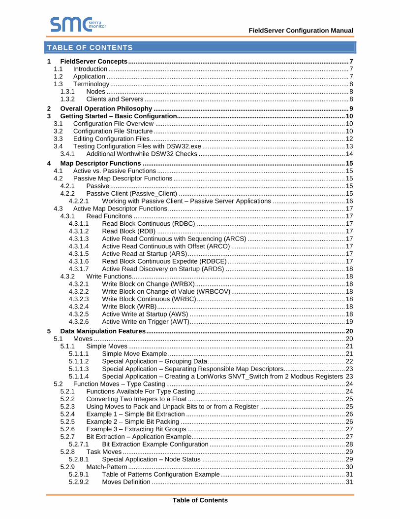
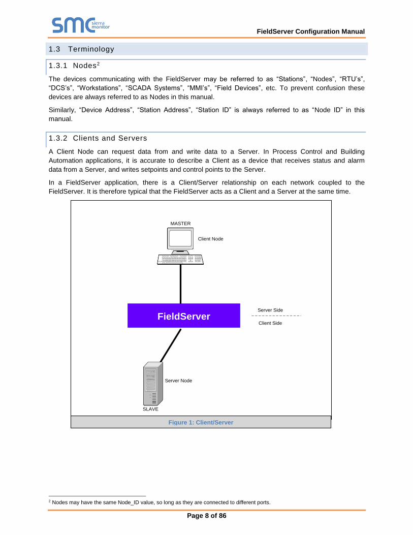
1.3.2 Clients and Servers
A Client Node can request data from and write data to a Server. In Process Control and Building
Automation applications, it is accurate to describe a Client as a device that receives status and alarm
data from a Server, and writes setpoints and control points to the Server.
In a FieldServer application, there is a Client/Server relationship on each network coupled to the
FieldServer. It is therefore typical that the FieldServer acts as a Client and a Server at the same time.
2 Nodes may have the same Node_ID value, so long as they are connected to different ports.
Figure 1: Client/Server
SLAVE
Server Side
Client Side
Server Node
Client Node
MASTER
FieldServer
FieldServer Configuration Manual
Page 9 of 86
Modbus
Data Highway Plus
Bridge
Data Arrays
Client Map Descriptors
Client Node Descriptors
Server Map Descriptors
Virtual Server Nodes
Location
ClientSide
ServerSide
Server Node
Client Node
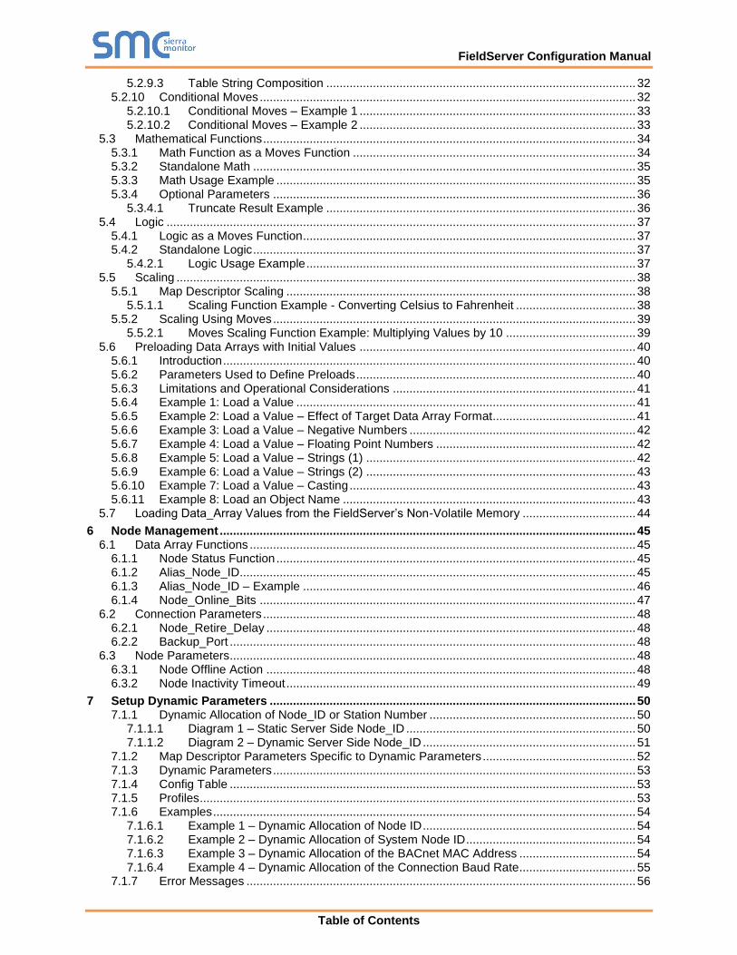
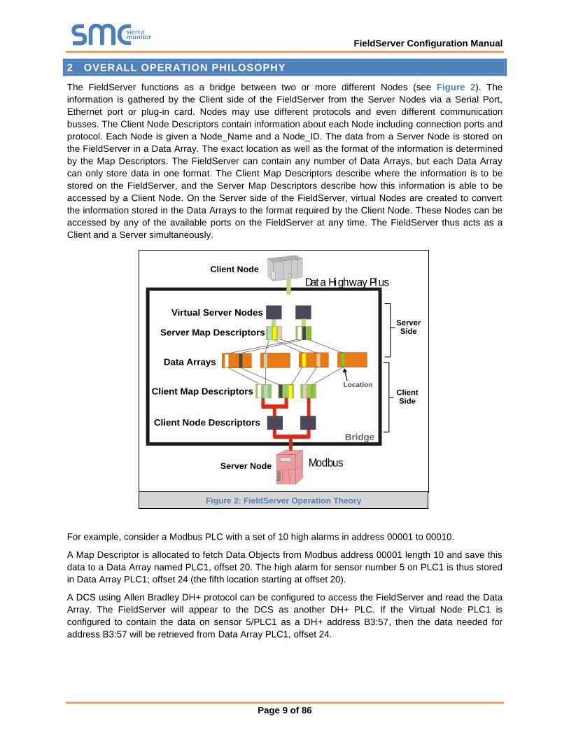
2 OVERALL OPERATION PHILOSOPHY
The FieldServer functions as a bridge between two or more different Nodes (see Figure 2). The
information is gathered by the Client side of the FieldServer from the Server Nodes via a Serial Port,
Ethernet port or plug-in card. Nodes may use different protocols and even different communication
busses. The Client Node Descriptors contain information about each Node including connection ports and
protocol. Each Node is given a Node_Name and a Node_ID. The data from a Server Node is stored on
the FieldServer in a Data Array. The exact location as well as the format of the information is determined
by the Map Descriptors. The FieldServer can contain any number of Data Arrays, but each Data Array
can only store data in one format. The Client Map Descriptors describe where the information is to be
stored on the FieldServer, and the Server Map Descriptors describe how this information is able to be
accessed by a Client Node. On the Server side of the FieldServer, virtual Nodes are created to convert
the information stored in the Data Arrays to the format required by the Client Node. These Nodes can be
accessed by any of the available ports on the FieldServer at any time. The FieldServer thus acts as a
Client and a Server simultaneously.
For example, consider a Modbus PLC with a set of 10 high alarms in address 00001 to 00010.
A Map Descriptor is allocated to fetch Data Objects from Modbus address 00001 length 10 and save this
data to a Data Array named PLC1, offset 20. The high alarm for sensor number 5 on PLC1 is thus stored
in Data Array PLC1; offset 24 (the fifth location starting at offset 20).
A DCS using Allen Bradley DH+ protocol can be configured to access the FieldServer and read the Data
Array. The FieldServer will appear to the DCS as another DH+ PLC. If the Virtual Node PLC1 is
configured to contain the data on sensor 5/PLC1 as a DH+ address B3:57, then the data needed for
address B3:57 will be retrieved from Data Array PLC1, offset 24.
Figure 2: FieldServer Operation Theory
FieldServer Configuration Manual
Page 10 of 86
3 GETTING STARTED – BASIC CONFIGURATION
3.1 Configuration File Overview
The default driver configuration file (CONFIG.CSV) for any driver combination ordered is loaded into the
FieldServer and can be retrieved using the Graphical User Interface Utility (see the FieldServer FS-GUI
Manual for more details). Use this file as a template when editing configuration files to ensure that the
edited file takes the correct form. A detailed explanation of the configuration file follows:
3.2 Configuration File Structure
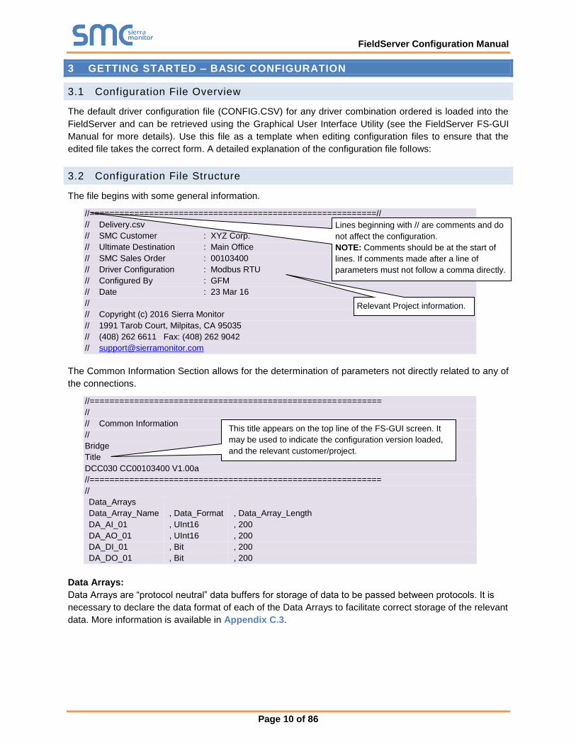
The file begins with some general information.
//==========================================================//
// Delivery.csv
// SMC Customer : XYZ Corp.
// Ultimate Destination : Main Office
// SMC Sales Order : 00103400
// Driver Configuration : Modbus RTU
// Configured By : GFM
// Date : 23 Mar 16
//
// Copyright (c) 2016 Sierra Monitor
// 1991 Tarob Court, Milpitas, CA 95035
// (408) 262 6611 Fax: (408) 262 9042
The Common Information Section allows for the determination of parameters not directly related to any of
the connections.
//===========================================================
//
// Common Information
//
Bridge
Title
DCC030 CC00103400 V1.00a
//===========================================================
//
Data_Arrays
Data_Array_Name , Data_Format , Data_Array_Length
DA_AI_01 , UInt16 , 200
DA_AO_01 , UInt16 , 200
DA_DI_01 , Bit , 200
DA_DO_01 , Bit , 200
Data Arrays:
Data Arrays are “protocol neutral” data buffers for storage of data to be passed between protocols. It is
necessary to declare the data format of each of the Data Arrays to facilitate correct storage of the relevant
data. More information is available in Appendix C.3.
Relevant Project information.
This title appears on the top line of the FS-GUI screen. It
may be used to indicate the configuration version loaded,
and the relevant customer/project.
Lines beginning with // are comments and do
not affect the configuration.
NOTE: Comments should be at the start of
lines. If comments made after a line of
parameters must not follow a comma directly.
FieldServer Configuration Manual
Page 11 of 86
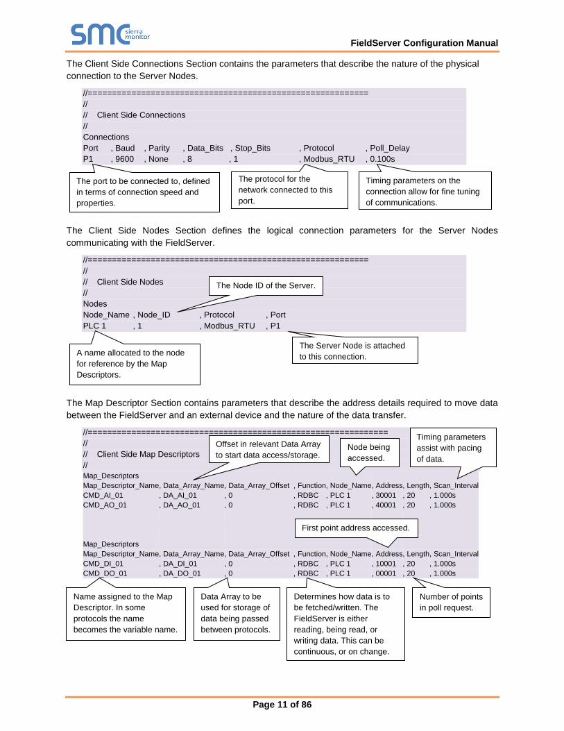
The Client Side Connections Section contains the parameters that describe the nature of the physical
connection to the Server Nodes.
//==========================================================
//
// Client Side Connections
//
Connections
Port , Baud , Parity , Data_Bits , Stop_Bits , Protocol , Poll_Delay
P1 , 9600 , None , 8 , 1 , Modbus_RTU , 0.100s
The Client Side Nodes Section defines the logical connection parameters for the Server Nodes
communicating with the FieldServer.
//==========================================================
//
// Client Side Nodes
//
Nodes
Node_Name , Node_ID , Protocol , Port
PLC 1 , 1 , Modbus_RTU , P1
The Map Descriptor Section contains parameters that describe the address details required to move data
between the FieldServer and an external device and the nature of the data transfer.
//==============================================================
//
// Client Side Map Descriptors
//
Map_Descriptors
Map_Descriptor_Name , Data_Array_Name , Data_Array_Offset , Function , Node_Name , Address , Length , Scan_Interval
CMD_AI_01 , DA_AI_01 , 0 , RDBC , PLC 1 , 30001 , 20 , 1.000s
CMD_AO_01 , DA_AO_01 , 0 , RDBC , PLC 1 , 40001 , 20 , 1.000s
Map_Descriptors
Map_Descriptor_Name , Data_Array_Name , Data_Array_Offset , Function , Node_Name , Address , Length , Scan_Interval
CMD_DI_01 , DA_DI_01 , 0 , RDBC , PLC 1 , 10001 , 20 , 1.000s
CMD_DO_01 , DA_DO_01 , 0 , RDBC , PLC 1 , 00001 , 20 , 1.000s
The port to be connected to, defined
in terms of connection speed and
properties.
The protocol for the
network connected to this
port.
Timing parameters on the
connection allow for fine tuning
of communications.
The Node ID of the Server.
Name assigned to the Map
Descriptor. In some
protocols the name
becomes the variable name.
Offset in relevant Data Array
to start data access/storage.
Data Array to be
used for storage of
data being passed
between protocols.
Determines how data is to
be fetched/written. The
FieldServer is either
reading, being read, or
writing data. This can be
continuous, or on change.
Node being
accessed.
First point address accessed.
Number of points
in poll request.
Timing parameters
assist with pacing
of data.
The Server Node is attached
to this connection. A name allocated to the node
for reference by the Map
Descriptors.
FieldServer Configuration Manual
Page 12 of 86
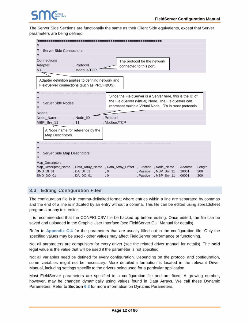
The Server Side Sections are functionally the same as their Client Side equivalents, except that Server
parameters are being defined.
/==========================================================
//
// Server Side Connections
//
Connections
Adapter , Protocol
N1 , Modbus/TCP
//==========================================================
//
// Server Side Nodes
//
Nodes
Node_Name , Node_ID , Protocol
MBP_Srv_11 , 11 , Modbus/TCP
//==============================================================
//
// Server Side Map Descriptors
//
Map_Descriptors
Map_Descriptor_Name , Data_Array_Name , Data_Array_Offset , Function , Node_Name , Address , Length
SMD_DI_01 , DA_DI_01 , 0 , Passive , MBP_Srv_11 , 10001 , 200
SMD_DO_01 , DA_DO_01 , 0 , Passive , MBP_Srv_11 , 00001 , 200
3.3 Editing Configuration Files
The configuration file is in comma-delimited format where entries within a line are separated by commas
and the end of a line is indicated by an entry without a comma. This file can be edited using spreadsheet
programs or any text editor.
It is recommended that the CONFIG.CSV file be backed up before editing. Once edited, the file can be
saved and uploaded in the Graphic User Interface (see FieldServer GUI Manual for details).
Refer to Appendix C.4 for the parameters that are usually filled out in the configuration file. Only the
specified values may be used - other values may affect FieldServer performance or functioning.
Not all parameters are compulsory for every driver (see the related driver manual for details). The bold
legal value is the value that will be used if the parameter is not specified.
Not all variables need be defined for every configuration. Depending on the protocol and configuration,
some variables might not be necessary. More detailed information is located in the relevant Driver
Manual, including settings specific to the drivers being used for a particular application.
Most FieldServer parameters are specified in a configuration file and are fixed. A growing number,
however, may be changed dynamically using values found in Data Arrays. We call these Dynamic
Parameters. Refer to Section 6.3 for more information on Dynamic Parameters.
Adapter definition applies to defining network and
FieldServer connections (such as PROFIBUS).
A Node name for reference by the
Map Descriptors.
Since the FieldServer is a Server here, this is the ID of
the FieldServer (virtual) Node. The FieldServer can
represent multiple Virtual Node_ID’s in most protocols.
The protocol for the network
connected to this port.
FieldServer Configuration Manual
Page 13 of 86
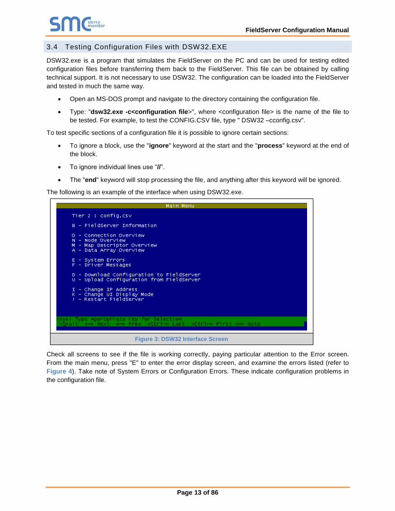
3.4 Testing Configuration Files with DSW32.EXE
DSW32.exe is a program that simulates the FieldServer on the PC and can be used for testing edited
configuration files before transferring them back to the FieldServer. This file can be obtained by calling
technical support. It is not necessary to use DSW32. The configuration can be loaded into the FieldServer
and tested in much the same way.
• Open an MS-DOS prompt and navigate to the directory containing the configuration file.
• Type: "dsw32.exe -c<configuration file>", where <configuration file> is the name of the file to
be tested. For example, to test the CONFIG.CSV file, type " DSW32 –cconfig.csv".
To test specific sections of a configuration file it is possible to ignore certain sections:
• To ignore a block, use the "ignore" keyword at the start and the "process" keyword at the end of
the block.
• To ignore individual lines use “//”.
• The "end" keyword will stop processing the file, and anything after this keyword will be ignored.
The following is an example of the interface when using DSW32.exe.
Check all screens to see if the file is working correctly, paying particular attention to the Error screen.
From the main menu, press "E" to enter the error display screen, and examine the errors listed (refer to
Figure 4). Take note of System Errors or Configuration Errors. These indicate configuration problems in
the configuration file.
Figure 3: DSW32 Interface Screen
FieldServer Configuration Manual
Page 14 of 86
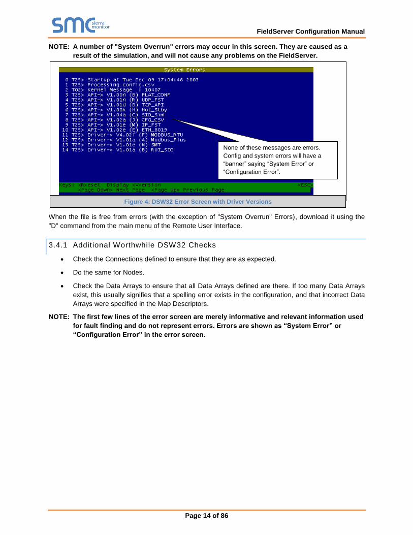
NOTE: A number of "System Overrun" errors may occur in this screen. They are caused as a
result of the simulation, and will not cause any problems on the FieldServer.
When the file is free from errors (with the exception of "System Overrun" Errors), download it using the
"D" command from the main menu of the Remote User Interface.
3.4.1 Additional Worthwhile DSW32 Checks
• Check the Connections defined to ensure that they are as expected.
• Do the same for Nodes.
• Check the Data Arrays to ensure that all Data Arrays defined are there. If too many Data Arrays
exist, this usually signifies that a spelling error exists in the configuration, and that incorrect Data
Arrays were specified in the Map Descriptors.
NOTE: The first few lines of the error screen are merely informative and relevant information used
for fault finding and do not represent errors. Errors are shown as “System Error” or
“Configuration Error” in the error screen.
None of these messages are errors.
Config and system errors will have a
“banner” saying “System Error” or
“Configuration Error”.
Figure 4: DSW32 Error Screen with Driver Versions
FieldServer Configuration Manual
Page 15 of 86
4 MAP DESCRIPTOR FUNCTIONS3
Map Descriptor functions determine how data is mapped between Data Arrays and the corresponding
driver data points. The choice of function used is critical in ensuring that the right relationship is
established with the device being communicated with. The most important decision to make when
choosing a function is whether the function needs to be active or passive. Once this is determined, the
trigger for initiating communications determines which active or passive function is used.
4.1 Active vs. Passive Functions
Active functions control the communications activity for the associated points in the network. Specifying
an active function for a point will enable the FieldServer to decide when a point is updated, and monitor
the health of the communications path for that point (if the associated protocol allows for this). Specifying
a passive function will mean that the FieldServer expects the communications for that point to be
controlled and monitored by another device on the associated network.
NOTE: By design, it is necessary that all active Map Descriptors communicate to a point that has
a passive mapping on the remote device, and that passive Map Descriptors are controlled
by an active mapping on the remote device.
There is a loose relationship between Active/Passive and Client/Server. Clients usually use active
mappings and Servers usually use passive mappings, however Active Servers and Passive Clients do
exist. Points that send an update to a network on change (such as Alarm panels) are a good example of
Active Servers.
Another set of terminology used in this area is solicited vs. unsolicited messages. A Client receives a
solicited message from a Server when it asks for it (the point is polled). A Client receives an unsolicited
message from a Server when the Server sends the point without the Client asking for it. Clients that send
solicited messages are Active Clients communicating with Passive Servers. Clients that receive
unsolicited messages are Passive Clients communicating with Active Servers.
4.2 Passive Map Descriptor Functions
4.2.1 Passive
The Passive function will not initiate any communications but waits to be solicited by a remote device and
responds with data accordingly. The Passive function will also accept writes and update the associated
Data Array.
4.2.2 Passive Client (Passive_Client)
The Passive_Client function is intended for use where the associated Map Descriptor performs a Client
function and is connected to an active Server. The Passive_Client function will consume all unsolicited
messages for the related point/s and store them in the associated Data Array.
3 Not all functions are supported by all drivers. Refer to the specific Driver Manual for information on functions supported by
individual drivers.
FieldServer Configuration Manual
Page 16 of 86
Data Server Client
Network Protocol A
FieldServer
Network Protocol B
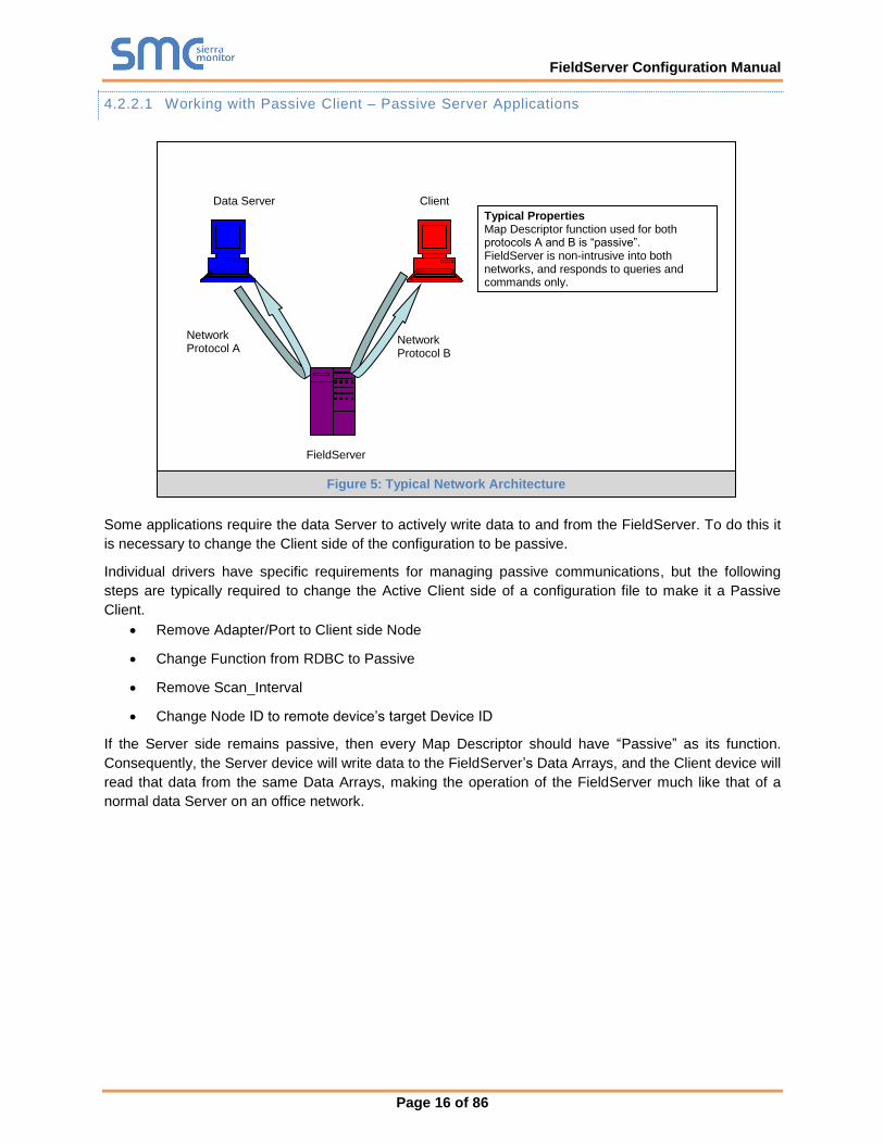
Typical Properties Map Descriptor function used for both protocols A and B is “passive”. FieldServer is non-intrusive into both networks, and responds to queries and commands only.
4.2.2.1 Working with Passive Client – Passive Server Applications
Some applications require the data Server to actively write data to and from the FieldServer. To do this it
is necessary to change the Client side of the configuration to be passive.
Individual drivers have specific requirements for managing passive communications, but the following
steps are typically required to change the Active Client side of a configuration file to make it a Passive
Client.
• Remove Adapter/Port to Client side Node
• Change Function from RDBC to Passive
• Remove Scan_Interval
• Change Node ID to remote device’s target Device ID
If the Server side remains passive, then every Map Descriptor should have “Passive” as its function.
Consequently, the Server device will write data to the FieldServer’s Data Arrays, and the Client device will
read that data from the same Data Arrays, making the operation of the FieldServer much like that of a
normal data Server on an office network.
Figure 5: Typical Network Architecture
FieldServer Configuration Manual
Page 17 of 86
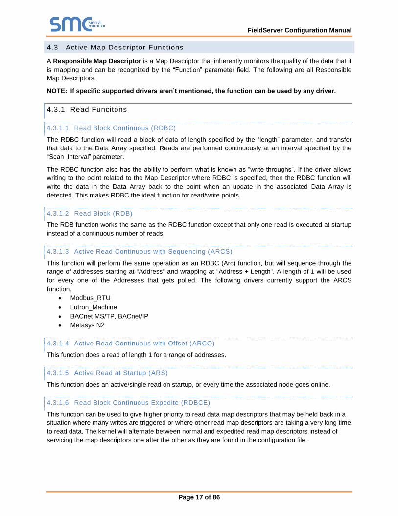
4.3 Active Map Descriptor Functions
A Responsible Map Descriptor is a Map Descriptor that inherently monitors the quality of the data that it
is mapping and can be recognized by the “Function” parameter field. The following are all Responsible
Map Descriptors.
NOTE: If specific supported drivers aren’t mentioned, the function can be used by any driver.
4.3.1 Read Funcitons
4.3.1.1 Read Block Continuous (RDBC)
The RDBC function will read a block of data of length specified by the “length” parameter, and transfer
that data to the Data Array specified. Reads are performed continuously at an interval specified by the
“Scan_Interval” parameter.
The RDBC function also has the ability to perform what is known as “write throughs”. If the driver allows
writing to the point related to the Map Descriptor where RDBC is specified, then the RDBC function will
write the data in the Data Array back to the point when an update in the associated Data Array is
detected. This makes RDBC the ideal function for read/write points.
4.3.1.2 Read Block (RDB)
The RDB function works the same as the RDBC function except that only one read is executed at startup
instead of a continuous number of reads.
4.3.1.3 Active Read Continuous with Sequencing (ARCS)
This function will perform the same operation as an RDBC (Arc) function, but will sequence through the
range of addresses starting at "Address" and wrapping at "Address + Length". A length of 1 will be used
for every one of the Addresses that gets polled. The following drivers currently support the ARCS
function.
• Modbus_RTU
• Lutron_Machine
• BACnet MS/TP, BACnet/IP
• Metasys N2
4.3.1.4 Active Read Continuous with Offset (ARCO)
This function does a read of length 1 for a range of addresses.
4.3.1.5 Active Read at Startup (ARS)
This function does an active/single read on startup, or every time the associated node goes online.
4.3.1.6 Read Block Continuous Expedite (RDBCE)
This function can be used to give higher priority to read data map descriptors that may be held back in a
situation where many writes are triggered or where other read map descriptors are taking a very long time
to read data. The kernel will alternate between normal and expedited read map descriptors instead of
servicing the map descriptors one after the other as they are found in the configuration file.
FieldServer Configuration Manual
Page 18 of 86
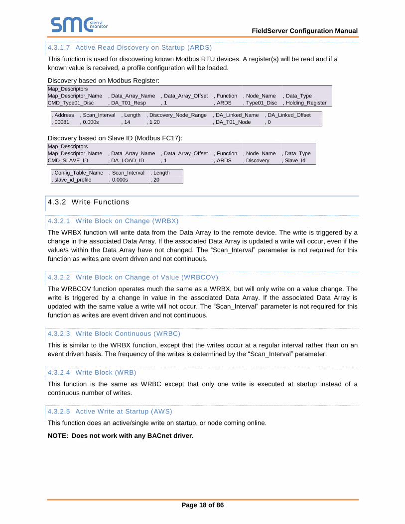
4.3.1.7 Active Read Discovery on Startup (ARDS)
This function is used for discovering known Modbus RTU devices. A register(s) will be read and if a
known value is received, a profile configuration will be loaded.
Discovery based on Modbus Register:
Map_Descriptors
Map_Descriptor_Name , Data_Array_Name , Data_Array_Offset , Function , Node_Name , Data_Type
CMD_Type01_Disc , DA_T01_Resp , 1 , ARDS , Type01_Disc , Holding_Register
, Address , Scan_Interval , Length , Discovery_Node_Range , DA_Linked_Name , DA_Linked_Offset
, 00081 , 0.000s , 14 , 1 20 , DA_T01_Node , 0
Discovery based on Slave ID (Modbus FC17):
Map_Descriptors
Map_Descriptor_Name , Data_Array_Name , Data_Array_Offset , Function , Node_Name , Data_Type
CMD_SLAVE_ID , DA_LOAD_ID , 1 , ARDS , Discovery , Slave_Id
, Config_Table_Name , Scan_Interval , Length
, slave_id_profile , 0.000s , 20
4.3.2 Write Functions
4.3.2.1 Write Block on Change (WRBX)
The WRBX function will write data from the Data Array to the remote device. The write is triggered by a
change in the associated Data Array. If the associated Data Array is updated a write will occur, even if the
value/s within the Data Array have not changed. The “Scan_Interval” parameter is not required for this
function as writes are event driven and not continuous.
4.3.2.2 Write Block on Change of Value (WRBCOV)
The WRBCOV function operates much the same as a WRBX, but will only write on a value change. The
write is triggered by a change in value in the associated Data Array. If the associated Data Array is
updated with the same value a write will not occur. The “Scan_Interval” parameter is not required for this
function as writes are event driven and not continuous.
4.3.2.3 Write Block Continuous (WRBC)
This is similar to the WRBX function, except that the writes occur at a regular interval rather than on an
event driven basis. The frequency of the writes is determined by the “Scan_Interval” parameter.
4.3.2.4 Write Block (WRB)
This function is the same as WRBC except that only one write is executed at startup instead of a
continuous number of writes.
4.3.2.5 Active Write at Startup (AWS)
This function does an active/single write on startup, or node coming online.
NOTE: Does not work with any BACnet driver.

FieldServer Configuration Manual
Page 19 of 86
4.3.2.6 Active Write on Trigger (AWT)
This function is used to affect a single data write per trigger. As with the WRBX function, the write only
occurs when the Data Array is updated. In this case the updated data is not used to form the write, but
updating the Data Array triggers a read of a Secondary Data Array which contains the data to be served
in the write.
In the example below (from the Lutron Machine Driver) the driver watches the Data Array called
‘Lut_triggers’ (offset 13). If that Data Array element is updated (even if the value remains unchanged) the
the write is triggered. The driver extracts the data from the Secondary Data Array called ‘Set_tlck’ (offset
0) and forms a message to write this data to the field device.
Only certain drivers support/require the use of this function. For other drivers, AWT is a synonym for
WRBX since there is no secondary Data Array to extract information from.
NOTE: The driver may extract more data from the array than specified by the ‘length’ parameter.
The only way to know how much data is to read that specific driver’s manual.
Map_Descriptors
Map_Descriptor_Name , Data_Array_Name , Data_Array_Offset , Function , Node_Name , GRAFIK_command
Set_tck , Lut_triggers , 13 , AWT , LUT_GRF6_0 , Set_tclk
, DA_Lut_List , DA_Lut_List_Offset , Length
, Set_tclk , 0 , 1

FieldServer Configuration Manual
Page 20 of 86
5 DATA MANIPULATION FEATURES
The features described in this section may or may not be needed depending on the application where the
FieldServer is implemented. If the application calls for straight passing of data without modification
through the FieldServer, then the features in this section will probably not be useful.
5.1 Moves
The Moves function permits data to be moved from one Data Array to another. The function parameter
within moves allows data manipulation to occur while moving the data. Examples of this are Logic
operation, Integer to floating point conversion, etc. Scaling, Logic and Math are also possible while
moving data.
With the exception of Conditional Moves (Section 5.2.9), each Data Array location may only act as the
target location of one Responsible Move. This ensures that the data source can be uniquely determined
in order to establish source data validity, and so that a write through the target data location is directed to
the appropriate location.
Moves will execute whenever the source data changes or the scan interval (if specified) expires. If a task
move does not have a scan interval defined, a default scan interval of one second is assumed.
A Move operation must specify the following elements:
Data Elements
Source_Data_Array The name of the Data Array from which data is to be copied.
Source_Offset The offset within the Data Array from which data is to be copied.
Target_Data_Array The name of the Data Array to which data is to be copied.
Target_Offset
The offset within the Data Array to which data is to be copied. The offset can
be either a hardcoded value or can be obtained from another data array. See
Moves example in Section 5.1.1.1 for more information.
Optional Elements
Length The number of consecutive source Data Array values to be moved to
consecutive target locations, starting at the respective offsets.
Task_Name If a task name is specified, the move operation becomes a continuous task on
the FieldServer that is executed at the scan interval specified.
Scan_Interval The time interval at which the task will be repeated. A task name must be
specified if a scan interval is specified.
Function Defines move functionality (for example byte order manipulation). Functions
are summarized in Section 5.2.
Conditional_Data_Array The name of a Data Array to be used for conditional moves. See Section
5.1.1.3 for more information.
Conditional_Offset
The offset into the Conditional_Data_Array where the conditional bits for the
move are defined. The value found at this specified location must be non-zero
for the move to be executed. If the value is zero, the move is inhibited.
FieldServer Configuration Manual
Page 21 of 86
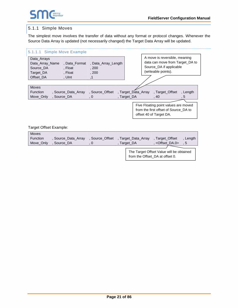
5.1.1 Simple Moves
The simplest move involves the transfer of data without any format or protocol changes. Whenever the
Source Data Array is updated (not necessarily changed) the Target Data Array will be updated.
5.1.1.1 Simple Move Example
Data_Arrays
Data_Array_Name , Data_Format , Data_Array_Length
Source_DA , Float , 200
Target_DA , Float , 200
Offset_DA , UInt ,1
Moves
Function , Source_Data_Array , Source_Offset , Target_Data_Array , Target_Offset , Length
Move_Only , Source_DA , 0 , Target_DA , 40 , 5
Target Offset Example:
Moves
Function , Source_Data_Array , Source_Offset , Target_Data_Array , Target_Offset , Length
Move_Only , Source_DA , 0 , Target_DA , <Offset_DA.0> , 5
Five Floating point values are moved
from the first offset of Source_DA to
offset 40 of Target DA.
A move is reversible, meaning
data can move from Target_DA to
Source_DA if applicable
(writeable points).
The Target Offset Value will be obtained
from the Offset_DA at offset 0.
FieldServer Configuration Manual
Page 22 of 86
Client side Data Array 1
Client side Data Array 4
Client side Data Array 2
Client side Data Array 3
Server Side Data
Array
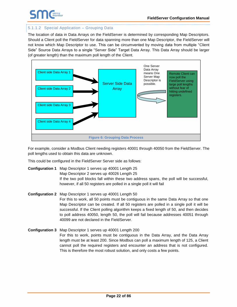
Remote Client can now poll the FieldServer using large poll lengths without fear of hitting undefined registers.
One Server Data Array means One Server Map Descriptor is possible.
5.1.1.2 Special Application – Grouping Data
The location of data in Data Arrays on the FieldServer is determined by corresponding Map Descriptors.
Should a Client poll the FieldServer for data spanning more than one Map Descriptor, the FieldServer will
not know which Map Descriptor to use. This can be circumvented by moving data from multiple “Client
Side” Source Data Arrays to a single “Server Side” Target Data Array. This Data Array should be larger
(of greater length) than the maximum poll length of the Client.
For example, consider a Modbus Client needing registers 40001 through 40050 from the FieldServer. The
poll lengths used to obtain this data are unknown.
This could be configured in the FieldServer Server side as follows:
Configuration 1 Map Descriptor 1 serves up 40001 Length 25
Map Descriptor 2 serves up 40026 Length 25
If the two poll blocks fall within these two address spans, the poll will be successful,
however, if all 50 registers are polled in a single poll it will fail
Configuration 2 Map Descriptor 1 serves up 40001 Length 50
For this to work, all 50 points must be contiguous in the same Data Array so that one
Map Descriptor can be created. If all 50 registers are polled in a single poll it will be
successful. If the Client polling algorithm keeps a fixed length of 50, and then decides
to poll address 40050, length 50, the poll will fail because addresses 40051 through
40099 are not declared in the FieldServer.
Configuration 3 Map Descriptor 1 serves up 40001 Length 200
For this to work, points must be contiguous in the Data Array, and the Data Array
length must be at least 200. Since Modbus can poll a maximum length of 125, a Client
cannot poll the required registers and encounter an address that is not configured.
This is therefore the most robust solution, and only costs a few points.
Figure 6: Grouping Data Process
FieldServer Configuration Manual
Page 23 of 86
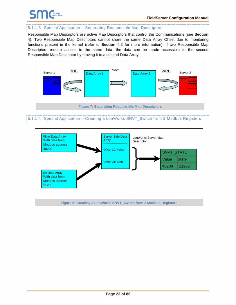
Data Array 1 Data Array 2 RDB
C
WRB
X
Move Server 1 Server 2
Float Data Array
With data from
Modbus address
40200
Bit Data Array
With data from
Modbus address
11235
Server Side Data Array -------------------------
Offset 20: Value
-------------------------
Offset 21: State
----------
SNVT_STATE
State Value
40200 11235
LonWorks Server Map Descriptor
5.1.1.3 Special Application – Separating Responsible Map Descriptors
Responsible Map Descriptors are active Map Descriptors that control the Communications (see Section
4). Two Responsible Map Descriptors cannot share the same Data Array Offset due to monitoring
functions present in the kernel (refer to Section 4.3 for more information). If two Responsible Map
Descriptors require access to the same data, the data can be made accessible to the second
Responsible Map Descriptor by moving it to a second Data Array.
5.1.1.4 Special Application – Creating a LonWorks SNVT_Switch from 2 Modbus Registers
Figure 7: Separating Responsible Map Descriptors
Figure 8: Creating a LonWorks SNVT_Switch from 2 Modbus Registers
FieldServer Configuration Manual
Page 24 of 86
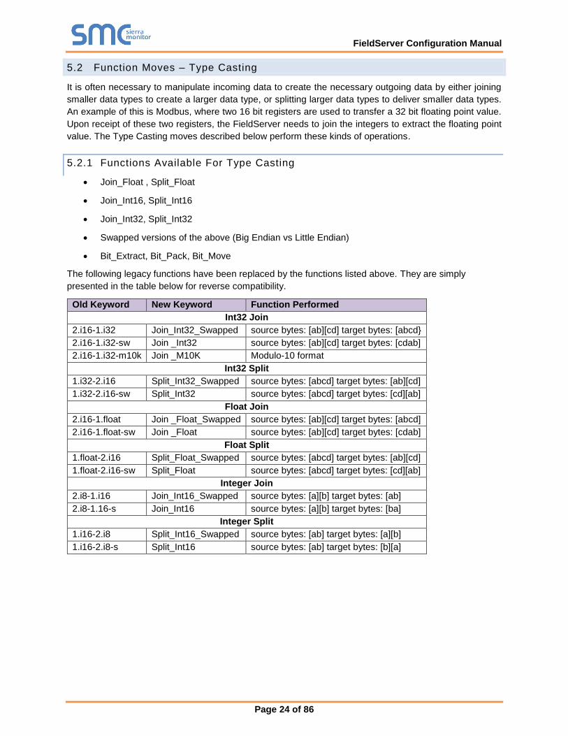
5.2 Function Moves – Type Casting
It is often necessary to manipulate incoming data to create the necessary outgoing data by either joining
smaller data types to create a larger data type, or splitting larger data types to deliver smaller data types.
An example of this is Modbus, where two 16 bit registers are used to transfer a 32 bit floating point value.
Upon receipt of these two registers, the FieldServer needs to join the integers to extract the floating point
value. The Type Casting moves described below perform these kinds of operations.
5.2.1 Functions Available For Type Casting
• Join_Float , Split_Float
• Join_Int16, Split_Int16
• Join_Int32, Split_Int32
• Swapped versions of the above (Big Endian vs Little Endian)
• Bit_Extract, Bit_Pack, Bit_Move
The following legacy functions have been replaced by the functions listed above. They are simply
presented in the table below for reverse compatibility.
Old Keyword New Keyword Function Performed
Int32 Join
2.i16-1.i32 Join_Int32_Swapped source bytes: [ab][cd] target bytes: [abcd}
2.i16-1.i32-sw Join _Int32 source bytes: [ab][cd] target bytes: [cdab]
2.i16-1.i32-m10k Join _M10K Modulo-10 format
Int32 Split
1.i32-2.i16 Split_Int32_Swapped source bytes: [abcd] target bytes: [ab][cd]
1.i32-2.i16-sw Split_Int32 source bytes: [abcd] target bytes: [cd][ab]
Float Join
2.i16-1.float Join _Float_Swapped source bytes: [ab][cd] target bytes: [abcd]
2.i16-1.float-sw Join _Float source bytes: [ab][cd] target bytes: [cdab]
Float Split
1.float-2.i16 Split_Float_Swapped source bytes: [abcd] target bytes: [ab][cd]
1.float-2.i16-sw Split_Float source bytes: [abcd] target bytes: [cd][ab]
Integer Join
2.i8-1.i16 Join_Int16_Swapped source bytes: [a][b] target bytes: [ab]
2.i8-1.16-s Join_Int16 source bytes: [a][b] target bytes: [ba]
Integer Split
1.i16-2.i8 Split_Int16_Swapped source bytes: [ab] target bytes: [a][b]
1.i16-2.i8-s Split_Int16 source bytes: [ab] target bytes: [b][a]
FieldServer Configuration Manual
Page 25 of 86
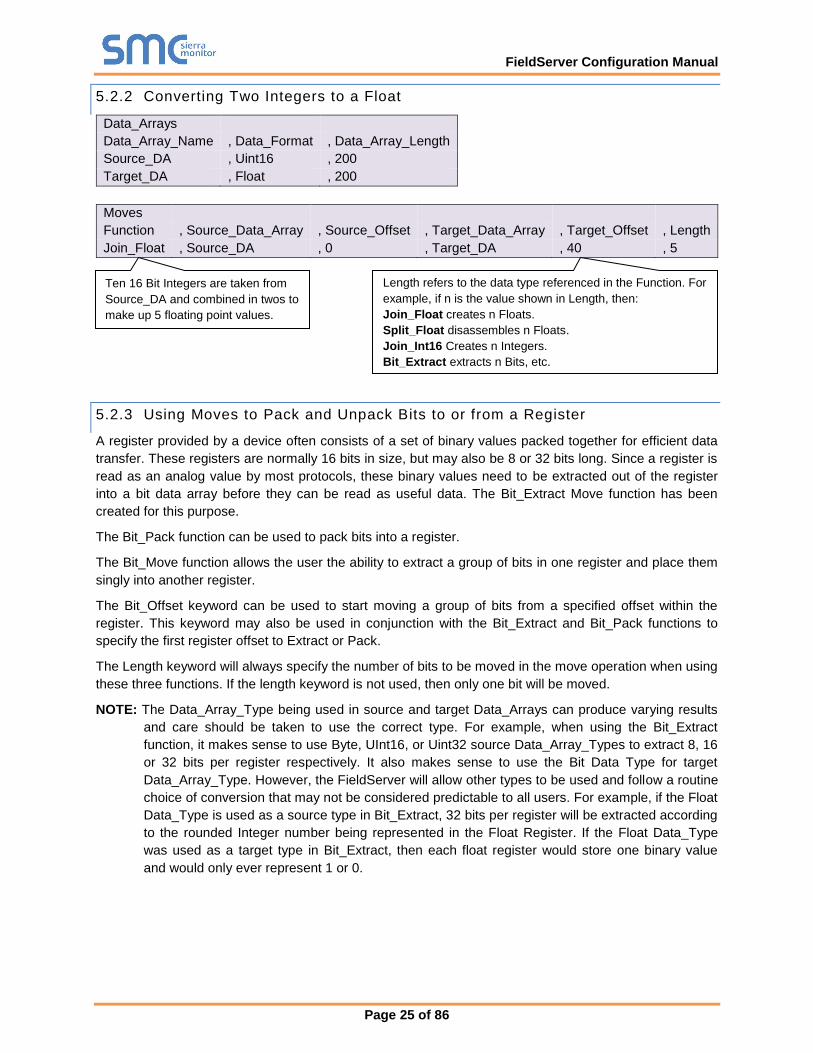
5.2.2 Converting Two Integers to a Float
Data_Arrays
Data_Array_Name , Data_Format , Data_Array_Length
Source_DA , Uint16 , 200
Target_DA , Float , 200
Moves
Function , Source_Data_Array , Source_Offset , Target_Data_Array , Target_Offset , Length
Join_Float , Source_DA , 0 , Target_DA , 40 , 5
5.2.3 Using Moves to Pack and Unpack Bits to or from a Register
A register provided by a device often consists of a set of binary values packed together for efficient data
transfer. These registers are normally 16 bits in size, but may also be 8 or 32 bits long. Since a register is
read as an analog value by most protocols, these binary values need to be extracted out of the register
into a bit data array before they can be read as useful data. The Bit_Extract Move function has been
created for this purpose.
The Bit_Pack function can be used to pack bits into a register.
The Bit_Move function allows the user the ability to extract a group of bits in one register and place them
singly into another register.
The Bit_Offset keyword can be used to start moving a group of bits from a specified offset within the
register. This keyword may also be used in conjunction with the Bit_Extract and Bit_Pack functions to
specify the first register offset to Extract or Pack.
The Length keyword will always specify the number of bits to be moved in the move operation when using
these three functions. If the length keyword is not used, then only one bit will be moved.
NOTE: The Data_Array_Type being used in source and target Data_Arrays can produce varying results
and care should be taken to use the correct type. For example, when using the Bit_Extract
function, it makes sense to use Byte, UInt16, or Uint32 source Data_Array_Types to extract 8, 16
or 32 bits per register respectively. It also makes sense to use the Bit Data Type for target
Data_Array_Type. However, the FieldServer will allow other types to be used and follow a routine
choice of conversion that may not be considered predictable to all users. For example, if the Float
Data_Type is used as a source type in Bit_Extract, 32 bits per register will be extracted according
to the rounded Integer number being represented in the Float Register. If the Float Data_Type
was used as a target type in Bit_Extract, then each float register would store one binary value
and would only ever represent 1 or 0.
Ten 16 Bit Integers are taken from
Source_DA and combined in twos to
make up 5 floating point values.
Length refers to the data type referenced in the Function. For
example, if n is the value shown in Length, then:
Join_Float creates n Floats.
Split_Float disassembles n Floats.
Join_Int16 Creates n Integers.
Bit_Extract extracts n Bits, etc.
FieldServer Configuration Manual
Page 26 of 86
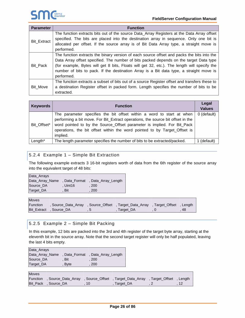
Parameter Function
Bit_Extract
The function extracts bits out of the source Data_Array Registers at the Data Array offset
specified. The bits are placed into the destination array in sequence. Only one bit is
allocated per offset. If the source array is of Bit Data Array type, a straight move is
performed.
Bit_Pack
The function extracts the binary version of each source offset and packs the bits into the
Data Array offset specified. The number of bits packed depends on the target Data type
(for example, Bytes will get 8 bits, Floats will get 32, etc.). The length will specify the
number of bits to pack. If the destination Array is a Bit data type, a straight move is
performed.
Bit_Move
The function extracts a subset of bits out of a source Register offset and transfers these to
a destination Register offset in packed form. Length specifies the number of bits to be
extracted.
Keywords Function Legal
Values
Bit_Offset*
The parameter specifies the bit offset within a word to start at when
performing a bit move. For Bit_Extract operations, the source bit offset in the
word pointed to by the Source_Offset parameter is implied. For Bit_Pack
operations, the bit offset within the word pointed to by Target_Offset is
implied.
0 (default)
Length* The length parameter specifies the number of bits to be extracted/packed. 1 (default)
5.2.4 Example 1 – Simple Bit Extraction
The following example extracts 3 16-bit registers worth of data from the 6th register of the source array
into the equivalent target of 48 bits:
Data_Arrays
Data_Array_Name , Data_Format , Data_Array_Length
Source_DA , Uint16 , 200
Target_DA , Bit , 200
Moves
Function , Source_Data_Array , Source_Offset , Target_Data_Array , Target_Offset , Length
Bit_Extract , Source_DA , 5 , Target_DA , 0 , 48
5.2.5 Example 2 – Simple Bit Packing
In this example, 12 bits are packed into the 3rd and 4th register of the target byte array, starting at the
eleventh bit in the source array. Note that the second target register will only be half populated, leaving
the last 4 bits empty.
Data_Arrays
Data_Array_Name , Data_Format , Data_Array_Length
Source_DA , Bit , 200
Target_DA , Byte , 200
Moves
Function , Source_Data_Array , Source_Offset , Target_Data_Array , Target_Offset , Length
Bit_Pack , Source_DA , 10 , Target_DA , 2 , 12
FieldServer Configuration Manual
Page 27 of 86
5.2.6 Example 3 – Extracting Bit Groups
The following example extracts 3 bits from the second byte of a 32-bit register and places them into a
byte register on their own. The Bit_Offset keyword is used here to achieve this:
Data_Arrays
Data_Array_Name , Data_Format , Data_Array_Length
Source_DA , Uint32 , 200
Target_DA , Byte , 200
Moves
Function , Source_Data_Array , Source_Offset , Bit_Offset , Target_Data_Array , Target_Offset , Length
Bit_Move , Source_DA , 0 , 8 , Target_DA , 0 , 3
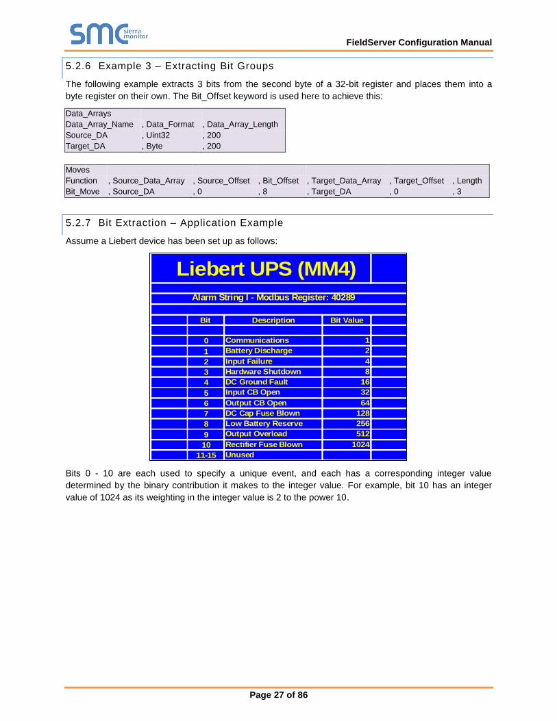
5.2.7 Bit Extraction – Application Example
Assume a Liebert device has been set up as follows:
Liebert UPS (MM4)
Alarm String I - Modbus Register: 40289
Bit Description Bit Value
0 Communications 1
1 Battery Discharge 2
2 Input Failure 4
3 Hardware Shutdown 8
4 DC Ground Fault 16
5 Input CB Open 32
6 Output CB Open 64
7 DC Cap Fuse Blown 128
8 Low Battery Reserve 256
9 Output Overload 512
10 Rectifier Fuse Blown 1024
11-15 Unused
Bits 0 - 10 are each used to specify a unique event, and each has a corresponding integer value
determined by the binary contribution it makes to the integer value. For example, bit 10 has an integer
value of 1024 as its weighting in the integer value is 2 to the power 10.
FieldServer Configuration Manual
Page 28 of 86
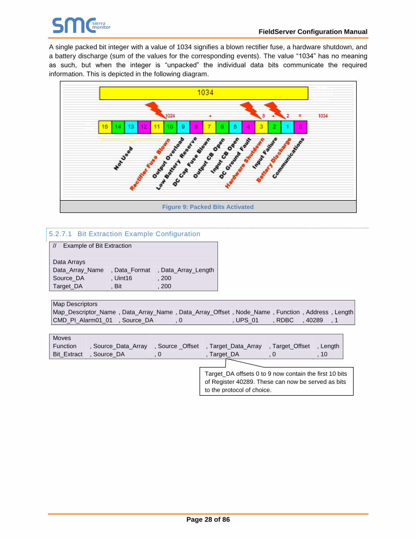
A single packed bit integer with a value of 1034 signifies a blown rectifier fuse, a hardware shutdown, and
a battery discharge (sum of the values for the corresponding events). The value “1034” has no meaning
as such, but when the integer is “unpacked” the individual data bits communicate the required
information. This is depicted in the following diagram.
5.2.7.1 Bit Extraction Example Configuration
// Example of Bit Extraction
Data Arrays
Data_Array_Name , Data_Format , Data_Array_Length
Source_DA , Uint16 , 200
Target_DA , Bit , 200
Map Descriptors
Map_Descriptor_Name , Data_Array_Name , Data_Array_Offset , Node_Name , Function , Address , Length
CMD_PI_Alarm01_01 , Source_DA , 0 , UPS_01 , RDBC , 40289 , 1
Moves
Function , Source_Data_Array , Source _Offset , Target_Data_Array , Target_Offset , Length
Bit_Extract , Source_DA , 0 , Target_DA , 0 , 10
Target_DA offsets 0 to 9 now contain the first 10 bits
of Register 40289. These can now be served as bits
to the protocol of choice.
Figure 9: Packed Bits Activated
FieldServer Configuration Manual
Page 29 of 86
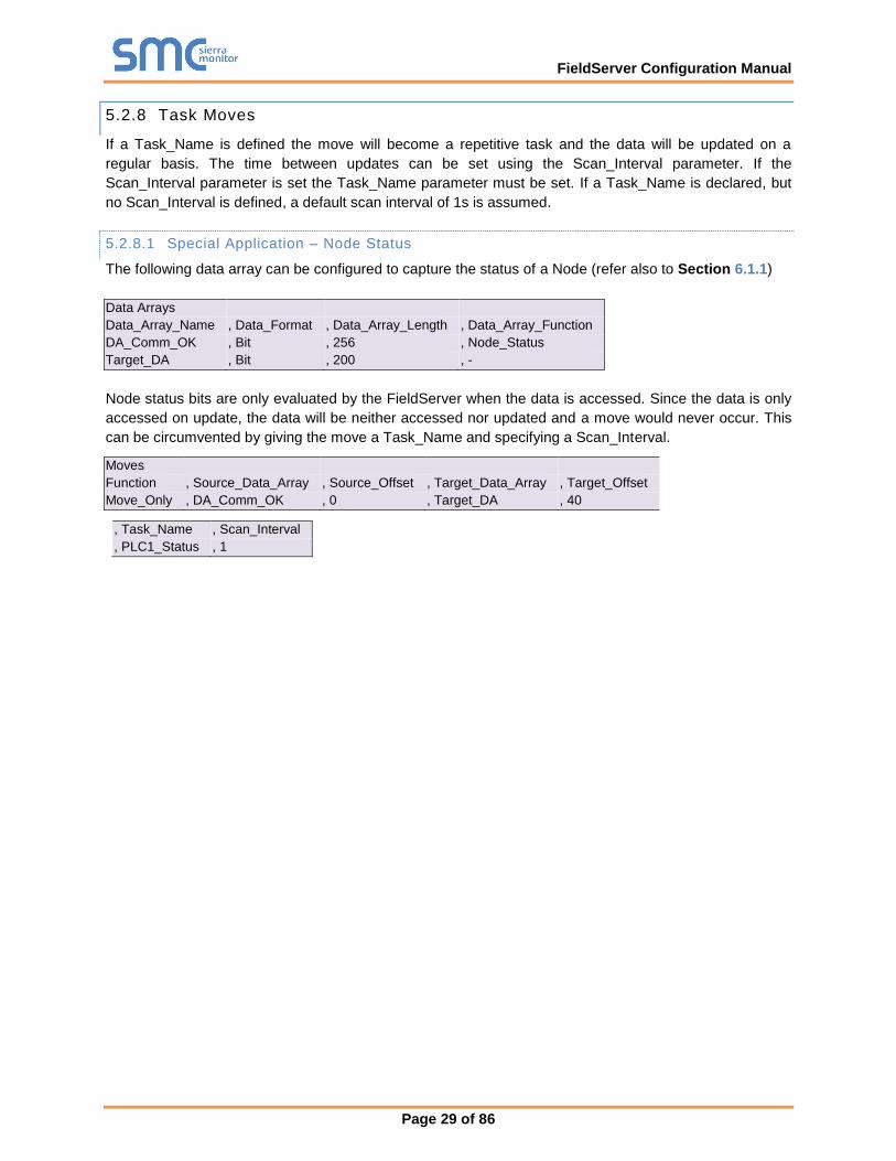
5.2.8 Task Moves
If a Task_Name is defined the move will become a repetitive task and the data will be updated on a
regular basis. The time between updates can be set using the Scan_Interval parameter. If the
Scan_Interval parameter is set the Task_Name parameter must be set. If a Task_Name is declared, but
no Scan_Interval is defined, a default scan interval of 1s is assumed.
5.2.8.1 Special Application – Node Status
The following data array can be configured to capture the status of a Node (refer also to Section 6.1.1)
Data Arrays
Data_Array_Name , Data_Format , Data_Array_Length , Data_Array_Function
DA_Comm_OK , Bit , 256 , Node_Status
Target_DA , Bit , 200 , -
Node status bits are only evaluated by the FieldServer when the data is accessed. Since the data is only
accessed on update, the data will be neither accessed nor updated and a move would never occur. This
can be circumvented by giving the move a Task_Name and specifying a Scan_Interval.
Moves
Function , Source_Data_Array , Source_Offset , Target_Data_Array , Target_Offset
Move_Only , DA_Comm_OK , 0 , Target_DA , 40
, Task_Name , Scan_Interval
, PLC1_Status , 1
FieldServer Configuration Manual
Page 30 of 86
5.2.9 Match-Pattern
The match pattern move is used at run time to move a customized single value based on combinations of
values in a Data Array as compared with preloaded customized criteria.
• The user builds a table of patterns (strings of tokens separated by “-“) each linked to a particular
location in a target Data Array.
• A “PATTERN DID NOT MATCH” string may also be defined and linked to a Data Array location.
• A pattern is built based on the values in the Data Array at run time by the move function.
• The pattern built at run time is compared with the preloaded table of patterns. The tokens in each
pattern must match exactly. If the preloaded pattern contains a wildcard (*), that token would not
be compared.
• If the pattern matches a pattern in the table, its value will be stored in the target Data Array at the
specified location.
• If the pattern does not match any of the preloaded patterns in the table a check is done for a
“PATTERN DID NOT MATCH” string in table. If found, the corresponding value will be stored in
the target Data Array.
• If a “PATTERN DID NOT MATCH” string is not defined, a default value of –1 will be stored and an
SDO will be generated prompting the user to add a “PATTERN DID NOT MATCH” record to the
table.
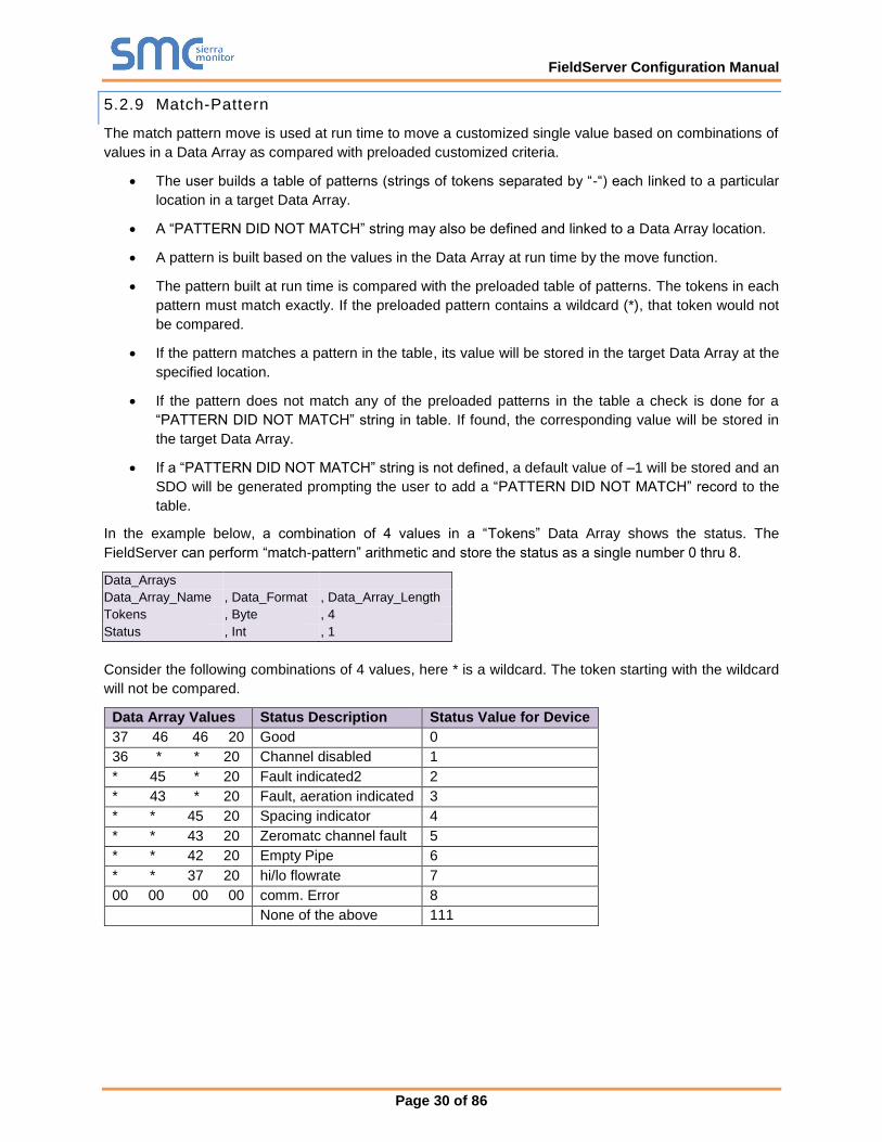
In the example below, a combination of 4 values in a “Tokens” Data Array shows the status. The
FieldServer can perform “match-pattern” arithmetic and store the status as a single number 0 thru 8.
Data_Arrays
Data_Array_Name , Data_Format , Data_Array_Length
Tokens , Byte , 4
Status , Int , 1
Consider the following combinations of 4 values, here * is a wildcard. The token starting with the wildcard
will not be compared.
Data Array Values Status Description Status Value for Device
37 46 46 20 Good 0
36 * * 20 Channel disabled 1
* 45 * 20 Fault indicated2 2
* 43 * 20 Fault, aeration indicated 3
* * 45 20 Spacing indicator 4
* * 43 20 Zeromatc channel fault 5
* * 42 20 Empty Pipe 6
* * 37 20 hi/lo flowrate 7
00 00 00 00 comm. Error 8
None of the above 111
FieldServer Configuration Manual
Page 31 of 86
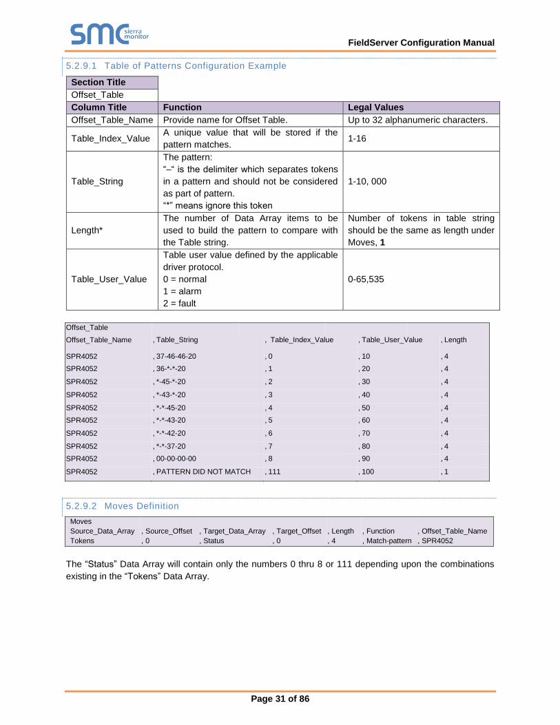
5.2.9.1 Table of Patterns Configuration Example
Section Title
Offset_Table
Column Title Function Legal Values
Offset_Table_Name Provide name for Offset Table. Up to 32 alphanumeric characters.
Table_Index_Value A unique value that will be stored if the
pattern matches. 1-16
Table_String
The pattern:
“–“ is the delimiter which separates tokens
in a pattern and should not be considered
as part of pattern.
“*” means ignore this token
1-10, 000
Length*
The number of Data Array items to be
used to build the pattern to compare with
the Table string.
Number of tokens in table string
should be the same as length under
Moves, 1
Table_User_Value
Table user value defined by the applicable
driver protocol.
0 = normal
1 = alarm
2 = fault
0-65,535
Offset_Table
Offset_Table_Name , Table_String , Table_Index_Value , Table_User_Value , Length
SPR4052 , 37-46-46-20 , 0 , 10 , 4
SPR4052 , 36-*-*-20 , 1 , 20 , 4
SPR4052 , *-45-*-20 , 2 , 30 , 4
SPR4052 , *-43-*-20 , 3 , 40 , 4
SPR4052 , *-*-45-20 , 4 , 50 , 4
SPR4052 , *-*-43-20 , 5 , 60 , 4
SPR4052 , *-*-42-20 , 6 , 70 , 4
SPR4052 , *-*-37-20 , 7 , 80 , 4
SPR4052 , 00-00-00-00 , 8 , 90 , 4
SPR4052 , PATTERN DID NOT MATCH , 111 , 100 , 1
5.2.9.2 Moves Definition
Moves
Source_Data_Array , Source_Offset , Target_Data_Array , Target_Offset , Length , Function , Offset_Table_Name
Tokens , 0 , Status , 0 , 4 , Match-pattern , SPR4052
The “Status” Data Array will contain only the numbers 0 thru 8 or 111 depending upon the combinations
existing in the “Tokens” Data Array.
FieldServer Configuration Manual
Page 32 of 86
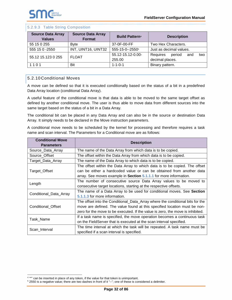
5.2.9.3 Table String Composition
Source Data Array
Values
Source Data Array
Format Build Pattern4 Description
55 15 0 255 Byte 37-0F-00-FF Two Hex Characters.
555 15 0 -2550 INT, UINT16, UINT32 555-15-0--25505 Just as decimal values.
55.12 15.123 0 255 FLOAT 55.12-15.12-0.00-
255.00
Requires period and two
decimal places.
1 1 0 1 Bit 1-1-0-1 Binary pattern.
5.2.10 Conditional Moves
A move can be defined so that it is executed conditionally based on the status of a bit in a predefined
Data Array location (conditional Data Array).
A useful feature of the conditional move is that data is able to be moved to the same target offset as
defined by another conditional move. The user is thus able to move data from different sources into the
same target based on the status of a bit in a Data Array.
The conditional bit can be placed in any Data Array and can also be in the source or destination Data
Array. It simply needs to be declared in the Move instruction parameters.
A conditional move needs to be scheduled by the kernel for processing and therefore requires a task
name and scan interval. The Parameters for a Conditional move are as follows:
Conditional Move
Parameters Description
Source_Data_Array The name of the Data Array from which data is to be copied.
Source_Offset The offset within the Data Array from which data is to be copied.
Target_Data_Array The name of the Data Array to which data is to be copied.
Target_Offset
The offset within the Data Array to which data is to be copied. The offset
can be either a hardcoded value or can be obtained from another data
array. See moves example in Section 5.1.1.1 for more information.
Length The number of consecutive source Data Array values to be moved to
consecutive target locations, starting at the respective offsets.
Conditional_Data_Array The name of a Data Array to be used for conditional moves. See Section
5.1.1.3 for more information.
Conditional_Offset
The offset into the Conditional_Data_Array where the conditional bits for the
move are defined. The value found at this specified location must be non-
zero for the move to be executed. If the value is zero, the move is inhibited.
Task_Name If a task name is specified, the move operation becomes a continuous task
on the FieldServer that is executed at the scan interval specified.
Scan_Interval The time interval at which the task will be repeated. A task name must be
specified if a scan interval is specified.
4 “*” can be inserted in place of any token, if the value for that token is unimportant. 5 2550 is a negative value; there are two dashes in front of it “--“; one of these is considered a delimiter.
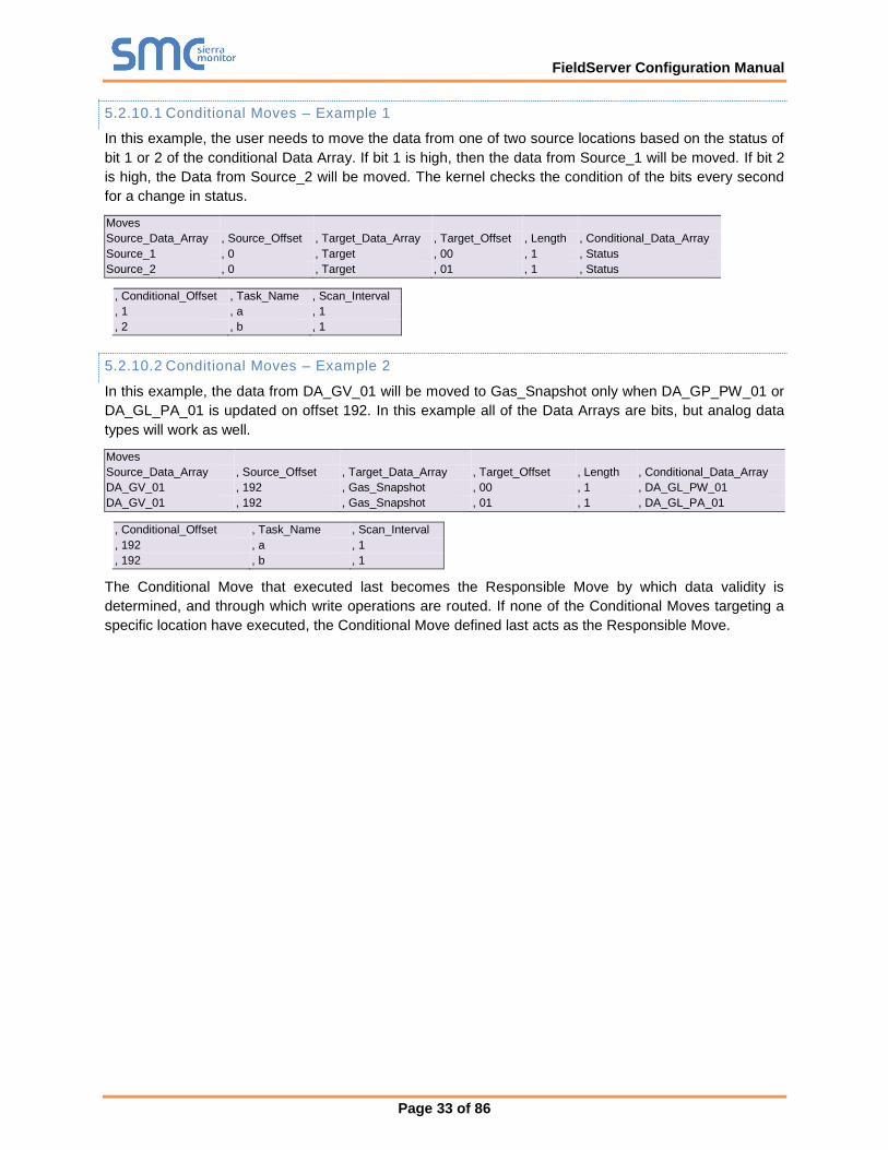
FieldServer Configuration Manual
Page 33 of 86
5.2.10.1 Conditional Moves – Example 1
In this example, the user needs to move the data from one of two source locations based on the status of
bit 1 or 2 of the conditional Data Array. If bit 1 is high, then the data from Source_1 will be moved. If bit 2
is high, the Data from Source_2 will be moved. The kernel checks the condition of the bits every second
for a change in status.
Moves
Source_Data_Array , Source_Offset , Target_Data_Array , Target_Offset , Length , Conditional_Data_Array
Source_1 , 0 , Target , 00 , 1 , Status
Source_2 , 0 , Target , 01 , 1 , Status
, Conditional_Offset , Task_Name , Scan_Interval
, 1 , a , 1
, 2 , b , 1
5.2.10.2 Conditional Moves – Example 2
In this example, the data from DA_GV_01 will be moved to Gas_Snapshot only when DA_GP_PW_01 or
DA_GL_PA_01 is updated on offset 192. In this example all of the Data Arrays are bits, but analog data
types will work as well.
Moves
Source_Data_Array , Source_Offset , Target_Data_Array , Target_Offset , Length , Conditional_Data_Array
DA_GV_01 , 192 , Gas_Snapshot , 00 , 1 , DA_GL_PW_01
DA_GV_01 , 192 , Gas_Snapshot , 01 , 1 , DA_GL_PA_01
, Conditional_Offset , Task_Name , Scan_Interval
, 192 , a , 1
, 192 , b , 1
The Conditional Move that executed last becomes the Responsible Move by which data validity is
determined, and through which write operations are routed. If none of the Conditional Moves targeting a
specific location have executed, the Conditional Move defined last acts as the Responsible Move.
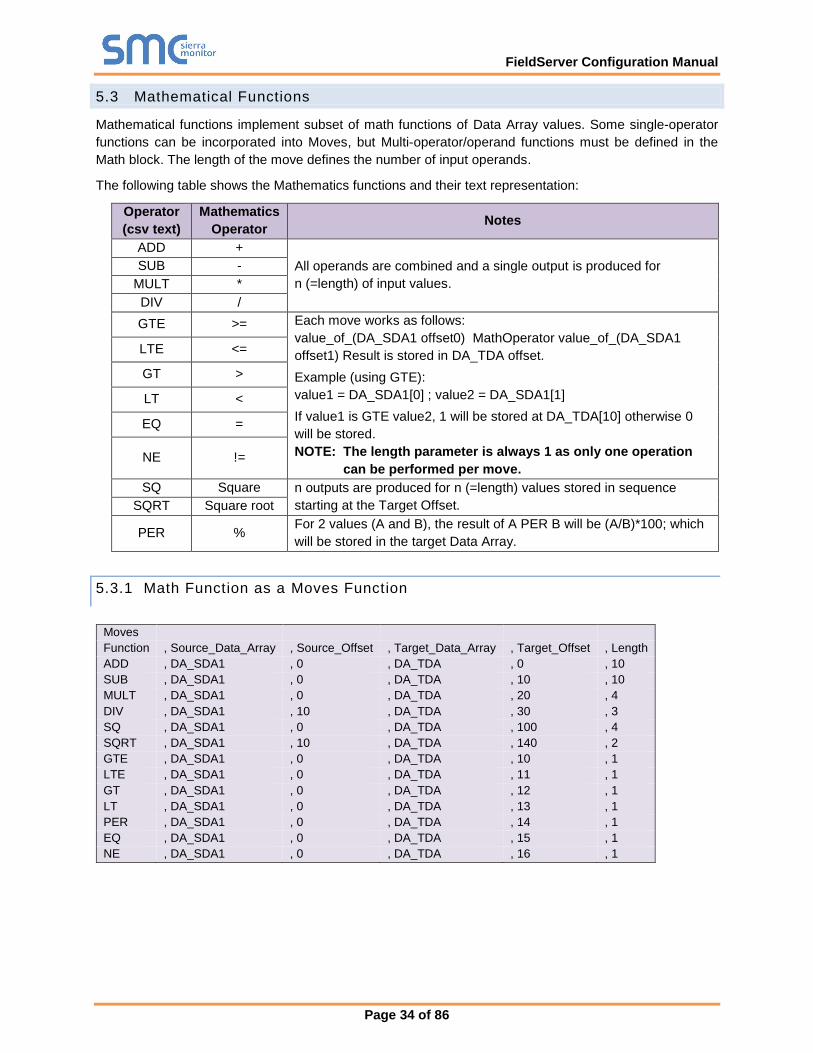
FieldServer Configuration Manual
Page 34 of 86
5.3 Mathematical Functions
Mathematical functions implement subset of math functions of Data Array values. Some single-operator
functions can be incorporated into Moves, but Multi-operator/operand functions must be defined in the
Math block. The length of the move defines the number of input operands.
The following table shows the Mathematics functions and their text representation:
Operator
(csv text)
Mathematics
Operator Notes
ADD +
All operands are combined and a single output is produced for
n (=length) of input values.
SUB -
MULT *
DIV /
GTE >= Each move works as follows:
value_of_(DA_SDA1 offset0) MathOperator value_of_(DA_SDA1
offset1) Result is stored in DA_TDA offset.
Example (using GTE):
value1 = DA_SDA1[0] ; value2 = DA_SDA1[1]
If value1 is GTE value2, 1 will be stored at DA_TDA[10] otherwise 0
will be stored.
NOTE: The length parameter is always 1 as only one operation
can be performed per move.
LTE <=
GT >
LT <
EQ =
NE !=
SQ Square n outputs are produced for n (=length) values stored in sequence
starting at the Target Offset. SQRT Square root
PER % For 2 values (A and B), the result of A PER B will be (A/B)*100; which
will be stored in the target Data Array.
5.3.1 Math Function as a Moves Function
Moves
Function , Source_Data_Array , Source_Offset , Target_Data_Array , Target_Offset , Length
ADD , DA_SDA1 , 0 , DA_TDA , 0 , 10
SUB , DA_SDA1 , 0 , DA_TDA , 10 , 10
MULT , DA_SDA1 , 0 , DA_TDA , 20 , 4
DIV , DA_SDA1 , 10 , DA_TDA , 30 , 3
SQ , DA_SDA1 , 0 , DA_TDA , 100 , 4
SQRT , DA_SDA1 , 10 , DA_TDA , 140 , 2
GTE , DA_SDA1 , 0 , DA_TDA , 10 , 1
LTE , DA_SDA1 , 0 , DA_TDA , 11 , 1
GT , DA_SDA1 , 0 , DA_TDA , 12 , 1
LT , DA_SDA1 , 0 , DA_TDA , 13 , 1
PER , DA_SDA1 , 0 , DA_TDA , 14 , 1
EQ , DA_SDA1 , 0 , DA_TDA , 15 , 1
NE , DA_SDA1 , 0 , DA_TDA , 16 , 1
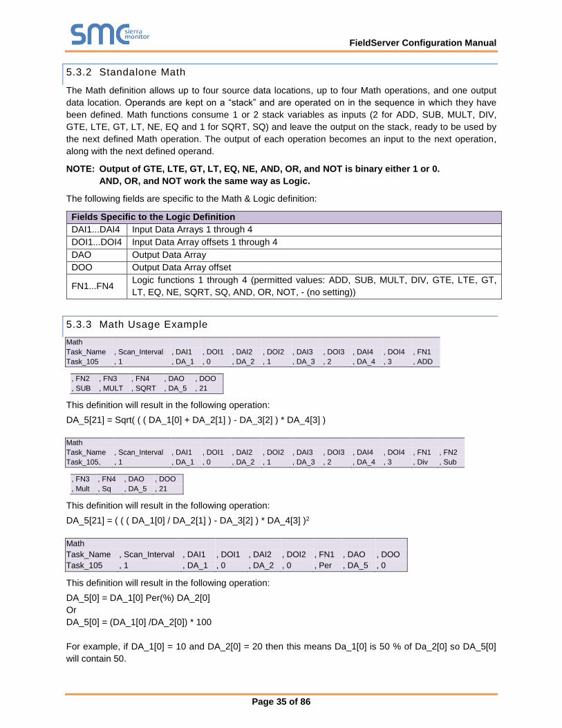
FieldServer Configuration Manual
Page 35 of 86
5.3.2 Standalone Math
The Math definition allows up to four source data locations, up to four Math operations, and one output
data location. Operands are kept on a “stack” and are operated on in the sequence in which they have
been defined. Math functions consume 1 or 2 stack variables as inputs (2 for ADD, SUB, MULT, DIV,
GTE, LTE, GT, LT, NE, EQ and 1 for SQRT, SQ) and leave the output on the stack, ready to be used by
the next defined Math operation. The output of each operation becomes an input to the next operation,
along with the next defined operand.
NOTE: Output of GTE, LTE, GT, LT, EQ, NE, AND, OR, and NOT is binary either 1 or 0.
AND, OR, and NOT work the same way as Logic.
The following fields are specific to the Math & Logic definition:
Fields Specific to the Logic Definition
DAI1...DAI4 Input Data Arrays 1 through 4
DOI1...DOI4 Input Data Array offsets 1 through 4
DAO Output Data Array
DOO Output Data Array offset
FN1...FN4 Logic functions 1 through 4 (permitted values: ADD, SUB, MULT, DIV, GTE, LTE, GT,
LT, EQ, NE, SQRT, SQ, AND, OR, NOT, - (no setting))
5.3.3 Math Usage Example
Math
Task_Name , Scan_Interval , DAI1 , DOI1 , DAI2 , DOI2 , DAI3 , DOI3 , DAI4 , DOI4 , FN1
Task_105 , 1 , DA_1 , 0 , DA_2 , 1 , DA_3 , 2 , DA_4 , 3 , ADD
, FN2 , FN3 , FN4 , DAO , DOO
, SUB , MULT , SQRT , DA_5 , 21
This definition will result in the following operation:
DA_5[21] = Sqrt( ( ( DA_1[0] + DA_2[1] ) - DA_3[2] ) * DA_4[3] )
Math
Task_Name , Scan_Interval , DAI1 , DOI1 , DAI2 , DOI2 , DAI3 , DOI3 , DAI4 , DOI4 , FN1 , FN2
Task_105, , 1 , DA_1 , 0 , DA_2 , 1 , DA_3 , 2 , DA_4 , 3 , Div , Sub
, FN3 , FN4 , DAO , DOO
, Mult , Sq , DA_5 , 21
This definition will result in the following operation:
DA_5[21] = ( ( ( DA_1[0] / DA_2[1] ) - DA_3[2] ) * DA_4[3] )2
Math
Task_Name , Scan_Interval , DAI1 , DOI1 , DAI2 , DOI2 , FN1 , DAO , DOO
Task_105 , 1 , DA_1 , 0 , DA_2 , 0 , Per , DA_5 , 0
This definition will result in the following operation:
DA_5[0] = DA_1[0] Per(%) DA_2[0]
Or
DA_5[0] = (DA_1[0] /DA_2[0]) * 100
For example, if DA_1[0] = 10 and DA_2[0] = 20 then this means Da_1[0] is 50 % of Da_2[0] so DA_5[0]
will contain 50.
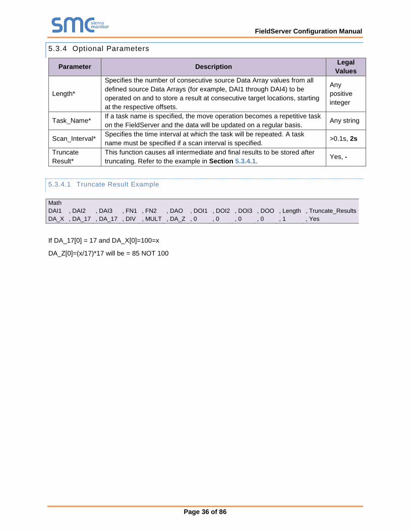
FieldServer Configuration Manual
Page 36 of 86
5.3.4 Optional Parameters
Parameter Description Legal
Values
Length*
Specifies the number of consecutive source Data Array values from all
defined source Data Arrays (for example, DAI1 through DAI4) to be
operated on and to store a result at consecutive target locations, starting
at the respective offsets.
Any
positive
integer
Task_Name* If a task name is specified, the move operation becomes a repetitive task
on the FieldServer and the data will be updated on a regular basis. Any string
Scan_Interval* Specifies the time interval at which the task will be repeated. A task
name must be specified if a scan interval is specified. >0.1s, 2s
Truncate
Result*
This function causes all intermediate and final results to be stored after
truncating. Refer to the example in Section 5.3.4.1. Yes, -
5.3.4.1 Truncate Result Example
Math
DAI1 , DAI2 , DAI3 , FN1 , FN2 , DAO , DOI1 , DOI2 , DOI3 , DOO , Length , Truncate_Results
DA_X , DA_17 , DA_17 , DIV , MULT , DA_Z , 0 , 0 , 0 , 0 , 1 , Yes
If DA_17[0] = 17 and DA_X[0]=100=x
DA_Z[0]=(x/17)*17 will be = 85 NOT 100
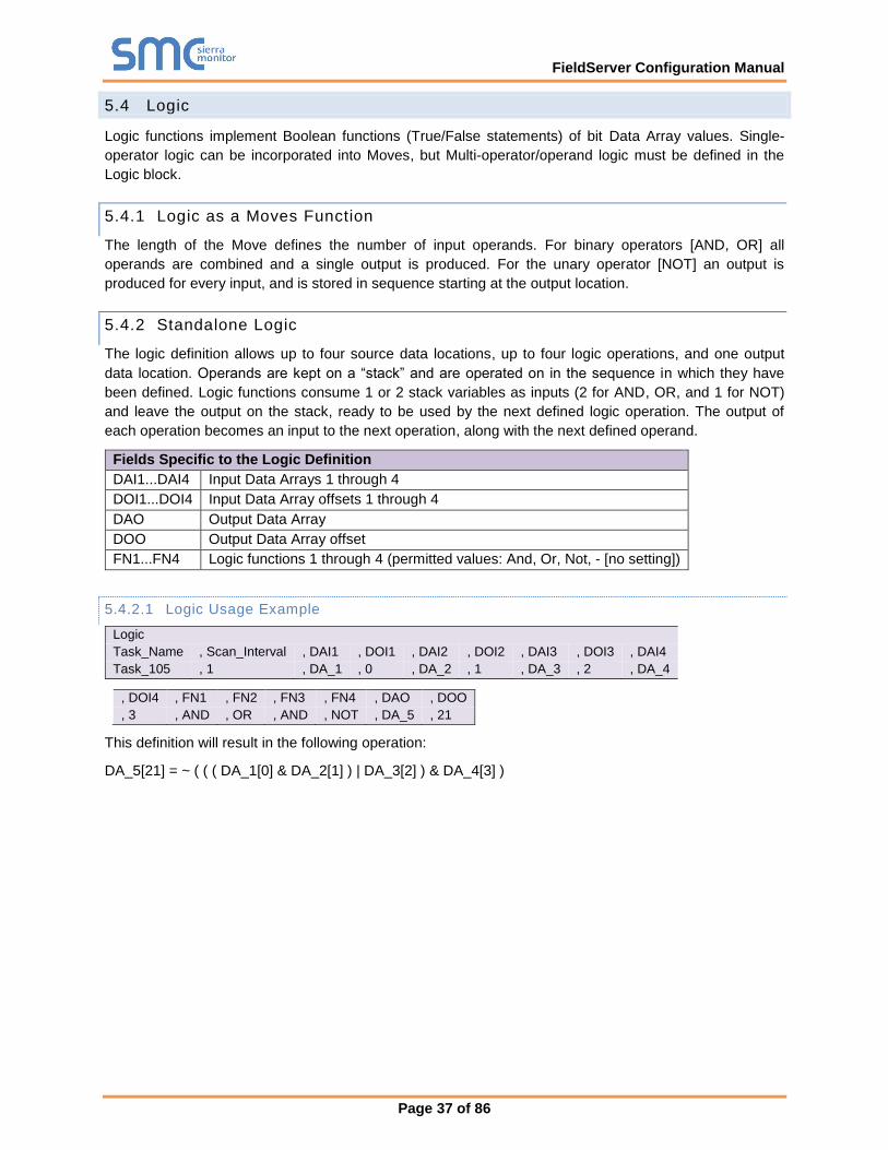
FieldServer Configuration Manual
Page 37 of 86
5.4 Logic
Logic functions implement Boolean functions (True/False statements) of bit Data Array values. Single-
operator logic can be incorporated into Moves, but Multi-operator/operand logic must be defined in the
Logic block.
5.4.1 Logic as a Moves Function
The length of the Move defines the number of input operands. For binary operators [AND, OR] all
operands are combined and a single output is produced. For the unary operator [NOT] an output is
produced for every input, and is stored in sequence starting at the output location.
5.4.2 Standalone Logic
The logic definition allows up to four source data locations, up to four logic operations, and one output
data location. Operands are kept on a “stack” and are operated on in the sequence in which they have
been defined. Logic functions consume 1 or 2 stack variables as inputs (2 for AND, OR, and 1 for NOT)
and leave the output on the stack, ready to be used by the next defined logic operation. The output of
each operation becomes an input to the next operation, along with the next defined operand.
Fields Specific to the Logic Definition
DAI1...DAI4 Input Data Arrays 1 through 4
DOI1...DOI4 Input Data Array offsets 1 through 4
DAO Output Data Array
DOO Output Data Array offset
FN1...FN4 Logic functions 1 through 4 (permitted values: And, Or, Not, - [no setting])
5.4.2.1 Logic Usage Example
Logic
Task_Name , Scan_Interval , DAI1 , DOI1 , DAI2 , DOI2 , DAI3 , DOI3 , DAI4
Task_105 , 1 , DA_1 , 0 , DA_2 , 1 , DA_3 , 2 , DA_4
, DOI4 , FN1 , FN2 , FN3 , FN4 , DAO , DOO
, 3 , AND , OR , AND , NOT , DA_5 , 21
This definition will result in the following operation:
DA_5[21] = ~ ( ( ( DA_1[0] & DA_2[1] ) | DA_3[2] ) & DA_4[3] )
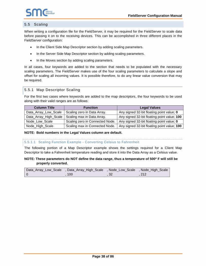
FieldServer Configuration Manual
Page 38 of 86
5.5 Scaling
When writing a configuration file for the FieldServer, it may be required for the FieldServer to scale data
before passing it on to the receiving devices. This can be accomplished in three different places in the
FieldServer configuration:
• In the Client Side Map Descriptor section by adding scaling parameters.
• In the Server Side Map Descriptor section by adding scaling parameters.
• In the Moves section by adding scaling parameters.
In all cases, four keywords are added to the section that needs to be populated with the necessary
scaling parameters. The FieldServer makes use of the four scaling parameters to calculate a slope and
offset for scaling all incoming values. It is possible therefore, to do any linear value conversion that may
be required.
5.5.1 Map Descriptor Scaling
For the first two cases where keywords are added to the map descriptors, the four keywords to be used
along with their valid ranges are as follows:
Column Title Function Legal Values
Data_Array_Low_Scale Scaling zero in Data Array. Any signed 32-bit floating point value; 0
Data_Array_High_Scale Scaling max in Data Array. Any signed 32-bit floating point value; 100
Node_Low_Scale Scaling zero in Connected Node. Any signed 32-bit floating point value; 0
Node_High_Scale Scaling max in Connected Node. Any signed 32-bit floating point value; 100
NOTE: Bold numbers in the Legal Values column are default.
5.5.1.1 Scaling Function Example - Converting Celsius to Fahrenheit
The following portion of a Map Descriptor example shows the settings required for a Client Map
Descriptor to take a Fahrenheit temperature reading and store it into the Data Array as a Celsius value.
NOTE: These parameters do NOT define the data range, thus a temperature of 500o F will still be
properly converted.
Data_Array_Low_Scale , Data_Array_High_Scale , Node_Low_Scale , Node_High_Scale
0 , 100 , 32 , 212
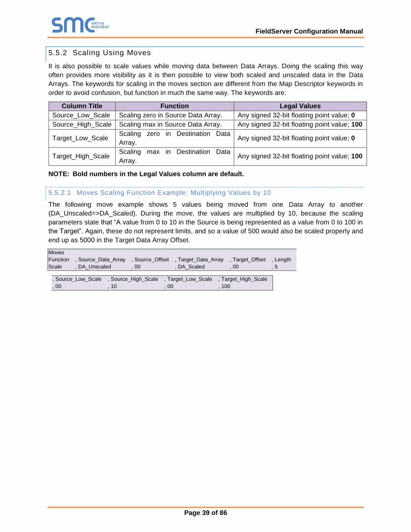
FieldServer Configuration Manual
Page 39 of 86
5.5.2 Scaling Using Moves
It is also possible to scale values while moving data between Data Arrays. Doing the scaling this way
often provides more visibility as it is then possible to view both scaled and unscaled data in the Data
Arrays. The keywords for scaling in the moves section are different from the Map Descriptor keywords in
order to avoid confusion, but function in much the same way. The keywords are:
Column Title Function Legal Values
Source_Low_Scale Scaling zero in Source Data Array. Any signed 32-bit floating point value; 0
Source_High_Scale Scaling max in Source Data Array. Any signed 32-bit floating point value; 100
Target_Low_Scale Scaling zero in Destination Data
Array. Any signed 32-bit floating point value; 0
Target_High_Scale Scaling max in Destination Data
Array. Any signed 32-bit floating point value; 100
NOTE: Bold numbers in the Legal Values column are default.
5.5.2.1 Moves Scaling Function Example: Multiplying Values by 10
The following move example shows 5 values being moved from one Data Array to another
(DA_Unscaled=>DA_Scaled). During the move, the values are multiplied by 10, because the scaling
parameters state that “A value from 0 to 10 in the Source is being represented as a value from 0 to 100 in
the Target”. Again, these do not represent limits, and so a value of 500 would also be scaled properly and
end up as 5000 in the Target Data Array Offset.
Moves
Function , Source_Data_Array , Source_Offset , Target_Data_Array , Target_Offset , Length
Scale , DA_Unscaled , 00 , DA_Scaled , 00 , 5
, Source_Low_Scale , Source_High_Scale , Target_Low_Scale , Target_High_Scale
, 00 , 10 , 00 , 100
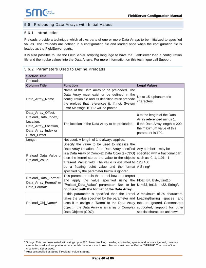
FieldServer Configuration Manual
Page 40 of 86
5.6 Preloading Data Arrays with Init ial Values
5.6.1 Introduction
Preloads provide a technique which allows parts of one or more Data Arrays to be initialized to specified
values. The Preloads are defined in a configuration file and loaded once when the configuration file is
loaded as the FieldServer starts.
It is also possible to use the FieldServer scripting language to have the FieldServer load a configuration
file and then poke values into the Data Arrays. For more information on this technique call Support.
5.6.2 Parameters Used to Define Preloads
Section Title
Preloads
Column Title Function Legal Values
Data_Array_Name
Name of the Data Array to be preloaded. The
Data Array must exist or be defined in the
configuration file and its definition must precede
the preload that references it. If not, System
Error Message 10117 will be printed.
Up to 15 alphanumeric
characters.
Data_Array_Offset,
Preload_Data_Index,
Location,
Data_Array_Location,
Data_Array_Index or
Buffer_Offset
The location in the Data Array to be preloaded.
0 to the length of the Data
Array referenced minus 1.
If the Data Array length is 200,
the maximum value of this
parameter is 199.
Length Not used. A length of 1 is always applied.
Preload_Data_Value or
Preload_Value
Specify the value to be used to initialize the
Data Array Location. If the Data Array specified
is a Data Array of Complex Data Objects (CDO)
then the kernel stores the value to the objects
‘Present_Value’ field. The value is assumed to
be a floating point value and the format
specified by the parameter below is ignored.
Any number – may be
specified with a fractional part,
such as: 0, 1, 1.01, -1,
123.456
A String6
Preload_Data_Format*,
Data_Array_Format* or
Data_Format*
This parameter tells the kernel how to interpret
and apply the value specified using the
“Preload_Data_Value” parameter. Not to be
confused with the format of the Data Array.
Float, Bit, Byte, Uint16,
Uint32, Int16, Int32, String7, -
Preload_Obj_Name*
If this parameter is specified then the kernel
takes the value specified by the parameter and
uses it to assign a ‘Name’ to the Data Array
object if the Data Array is an array of Complex
Data Objects (CDO).
A maximum of 39 characters.
Leading/trailing spaces and
tabs are ignored. Commas not
supported; support for other
special characters unknown. -
6 Strings: This has been tested with strings up to 320 characters long. Leading and trailing spaces and tabs are ignored, commas
cannot be used and support for other special characters is unknown. Format must be specified as ‘STRING’. The case of the characters is preserved.
7 Must be specified as String if Preload_Value is String.
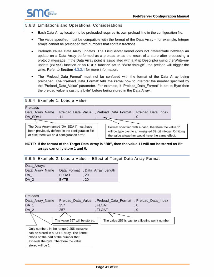
FieldServer Configuration Manual
Page 41 of 86
5.6.3 Limitations and Operational Considerations
• Each Data Array location to be preloaded requires its own preload line in the configuration file.
• The value specified must be compatible with the format of the Data Array – for example, Integer
arrays cannot be preloaded with numbers that contain fractions.
• Preloads cause Data Array updates. The FieldServer kernel does not differentiate between an
update on a Data Array performed as a preload or as the result of a store after processing a
protocol message. If the Data Array point is associated with a Map Descriptor using the Write-on-
update (WRBX) function or an RDBX function set to “Write through”, the preload will trigger the
write. Refer to Section 4.3.2.1 for more information.
• The ‘Preload_Data_Format’ must not be confused with the format of the Data Array being
preloaded. The ‘Preload_Data_Format’ tells the kernel how to interpret the number specified by
the ‘Preload_Data_Value’ parameter. For example, if ‘Preload_Data_Format’ is set to Byte then
the preload value is cast to a byte* before being stored in the Data Array.
5.6.4 Example 1: Load a Value
Preloads
Data_Array_Name , Preload_Data_Value , Preload_Data_Format , Preload_Data_Index
DA_SDA1 , 11 , - , 0
NOTE: If the format of the Target Data Array is “Bit”, then the value 11 will not be stored as Bit
arrays can only store 1 and 0.
5.6.5 Example 2: Load a Value – Effect of Target Data Array Format
Data_Arrays
Data_Array_Name , Data_Format , Data_Array_Length
DA_1 , FLOAT , 20
DA_2 , BYTE , 20
Preloads
Data_Array_Name , Preload_Data_Value , Preload_Data_Format , Preload_Data_Index
DA_1 , 257 , FLOAT , 0
DA_2 , 257 , FLOAT , 0
The Data Array named ‘DA_SDA1’ must have
been previously defined in the configuration file
or else there will be a configuration error.
Format specified with a dash, therefore the value 11
will be type cast to an unsigned 32-bit integer. Omitting
the value altogether would have the same effect.
The value 257 is cast to a floating point number. The value 257 will be stored.
Only numbers in the range 0-255 inclusive
can be stored in a BYTE array. The kernel
chops off the part of the number that
exceeds the byte. Therefore the value
stored will be 1.
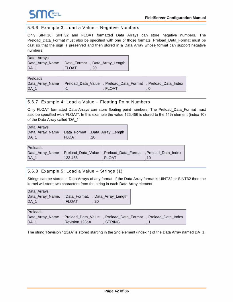
FieldServer Configuration Manual
Page 42 of 86
5.6.6 Example 3: Load a Value – Negative Numbers
Only SINT16, SINT32 and FLOAT formatted Data Arrays can store negative numbers. The
Preload_Data_Format must also be specified with one of those formats. Preload_Data_Format must be
cast so that the sign is preserved and then stored in a Data Array whose format can support negative
numbers.
Data_Arrays
Data_Array_Name , Data_Format , Data_Array_Length
DA_1 , FLOAT , 20
Preloads
Data_Array_Name , Preload_Data_Value , Preload_Data_Format , Preload_Data_Index
DA_1 , -1 , FLOAT , 0
5.6.7 Example 4: Load a Value – Floating Point Numbers
Only FLOAT formatted Data Arrays can store floating point numbers. The Preload_Data_Format must
also be specified with ‘FLOAT’. In this example the value 123.456 is stored to the 11th element (index 10)
of the Data Array called ‘DA_1’.
Data_Arrays
Data_Array_Name , Data_Format , Data_Array_Length
DA_1 , FLOAT , 20
Preloads
Data_Array_Name , Preload_Data_Value , Preload_Data_Format , Preload_Data_Index
DA_1 , 123.456 , FLOAT , 10
5.6.8 Example 5: Load a Value – Strings (1)
Strings can be stored in Data Arrays of any format. If the Data Array format is UINT32 or SINT32 then the
kernel will store two characters from the string in each Data Array element.
Data_Arrays
Data_Array_Name, , Data_Format, , Data_Array_Length
DA_1 , FLOAT , 20
Preloads
Data_Array_Name , Preload_Data_Value , Preload_Data_Format , Preload_Data_Index
DA_1 , Revision 123aA , STRING , 1
The string ‘Revision 123aA’ is stored starting in the 2nd element (index 1) of the Data Array named DA_1.
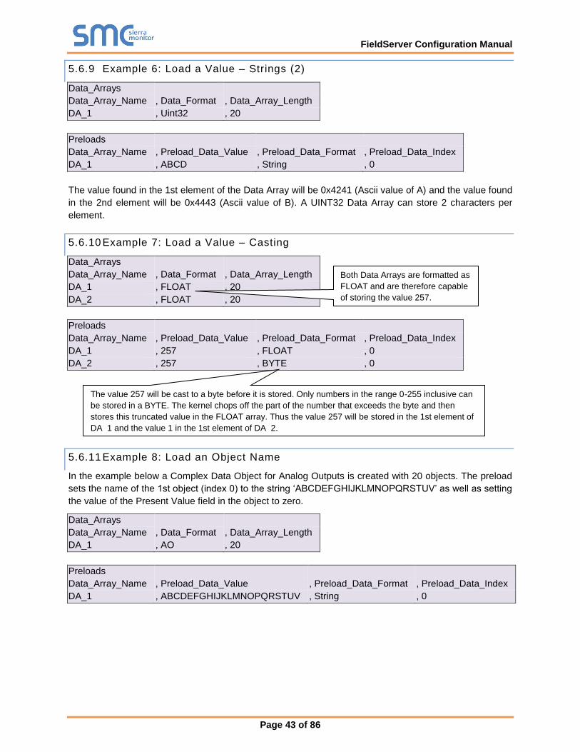
FieldServer Configuration Manual
Page 43 of 86
5.6.9 Example 6: Load a Value – Strings (2)
Data_Arrays
Data_Array_Name , Data_Format , Data_Array_Length
DA_1 , Uint32 , 20
Preloads
Data_Array_Name , Preload_Data_Value , Preload_Data_Format , Preload_Data_Index
DA_1 , ABCD , String , 0
The value found in the 1st element of the Data Array will be 0x4241 (Ascii value of A) and the value found
in the 2nd element will be 0x4443 (Ascii value of B). A UINT32 Data Array can store 2 characters per
element.
5.6.10 Example 7: Load a Value – Casting
Data_Arrays
Data_Array_Name , Data_Format , Data_Array_Length
DA_1 , FLOAT , 20
DA_2 , FLOAT , 20
Preloads
Data_Array_Name , Preload_Data_Value , Preload_Data_Format , Preload_Data_Index
DA_1 , 257 , FLOAT , 0
DA_2 , 257 , BYTE , 0
5.6.11 Example 8: Load an Object Name
In the example below a Complex Data Object for Analog Outputs is created with 20 objects. The preload
sets the name of the 1st object (index 0) to the string ‘ABCDEFGHIJKLMNOPQRSTUV’ as well as setting
the value of the Present Value field in the object to zero.
Data_Arrays
Data_Array_Name , Data_Format , Data_Array_Length
DA_1 , AO , 20
Preloads
Data_Array_Name , Preload_Data_Value , Preload_Data_Format , Preload_Data_Index
DA_1 , ABCDEFGHIJKLMNOPQRSTUV , String , 0
The value 257 will be cast to a byte before it is stored. Only numbers in the range 0-255 inclusive can
be stored in a BYTE. The kernel chops off the part of the number that exceeds the byte and then
stores this truncated value in the FLOAT array. Thus the value 257 will be stored in the 1st element of
DA_1 and the value 1 in the 1st element of DA_2.
Both Data Arrays are formatted as
FLOAT and are therefore capable
of storing the value 257.
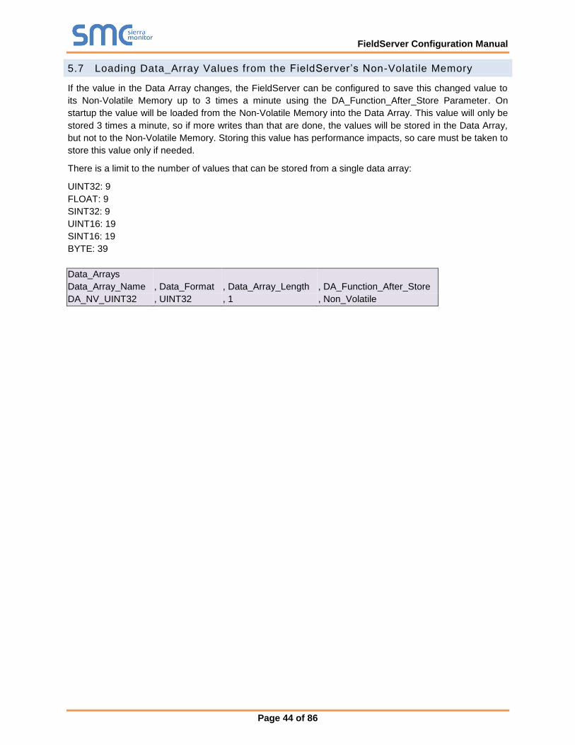
FieldServer Configuration Manual
Page 44 of 86
5.7 Loading Data_Array Values from the FieldServer’s Non-Volatile Memory
If the value in the Data Array changes, the FieldServer can be configured to save this changed value to
its Non-Volatile Memory up to 3 times a minute using the DA_Function_After_Store Parameter. On
startup the value will be loaded from the Non-Volatile Memory into the Data Array. This value will only be
stored 3 times a minute, so if more writes than that are done, the values will be stored in the Data Array,
but not to the Non-Volatile Memory. Storing this value has performance impacts, so care must be taken to
store this value only if needed.
There is a limit to the number of values that can be stored from a single data array:
UINT32: 9
FLOAT: 9
SINT32: 9
UINT16: 19
SINT16: 19
BYTE: 39
Data_Arrays
Data_Array_Name , Data_Format , Data_Array_Length , DA_Function_After_Store
DA_NV_UINT32 , UINT32 , 1 , Non_Volatile
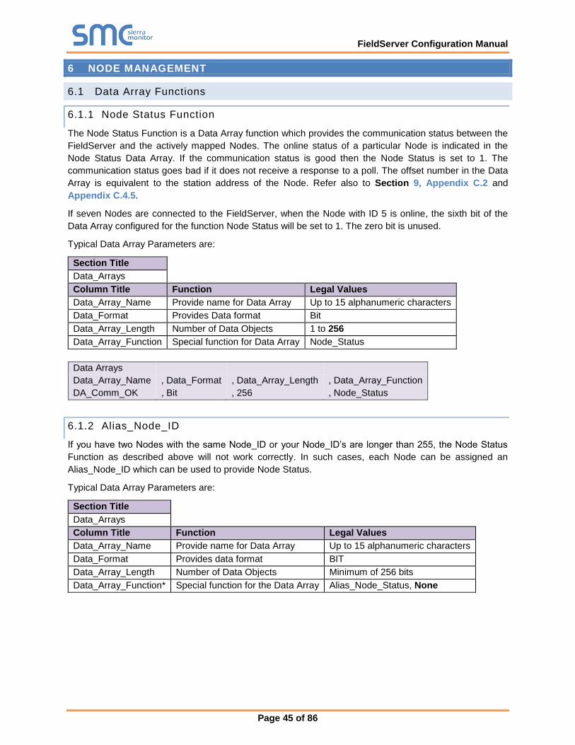
FieldServer Configuration Manual
Page 45 of 86
6 NODE MANAGEMENT
6.1 Data Array Functions
6.1.1 Node Status Function
The Node Status Function is a Data Array function which provides the communication status between the
FieldServer and the actively mapped Nodes. The online status of a particular Node is indicated in the
Node Status Data Array. If the communication status is good then the Node Status is set to 1. The
communication status goes bad if it does not receive a response to a poll. The offset number in the Data
Array is equivalent to the station address of the Node. Refer also to Section 9, Appendix C.2 and
Appendix C.4.5.
If seven Nodes are connected to the FieldServer, when the Node with ID 5 is online, the sixth bit of the
Data Array configured for the function Node Status will be set to 1. The zero bit is unused.
Typical Data Array Parameters are:
Section Title
Data_Arrays
Column Title Function Legal Values
Data_Array_Name Provide name for Data Array Up to 15 alphanumeric characters
Data_Format Provides Data format Bit
Data_Array_Length Number of Data Objects 1 to 256
Data_Array_Function Special function for Data Array Node_Status
Data Arrays
Data_Array_Name , Data_Format , Data_Array_Length , Data_Array_Function
DA_Comm_OK , Bit , 256 , Node_Status
6.1.2 Alias_Node_ID
If you have two Nodes with the same Node_ID or your Node_ID’s are longer than 255, the Node Status
Function as described above will not work correctly. In such cases, each Node can be assigned an
Alias_Node_ID which can be used to provide Node Status.
Typical Data Array Parameters are:
Section Title
Data_Arrays
Column Title Function Legal Values
Data_Array_Name Provide name for Data Array Up to 15 alphanumeric characters
Data_Format Provides data format BIT
Data_Array_Length Number of Data Objects Minimum of 256 bits
Data_Array_Function* Special function for the Data Array Alias_Node_Status, None
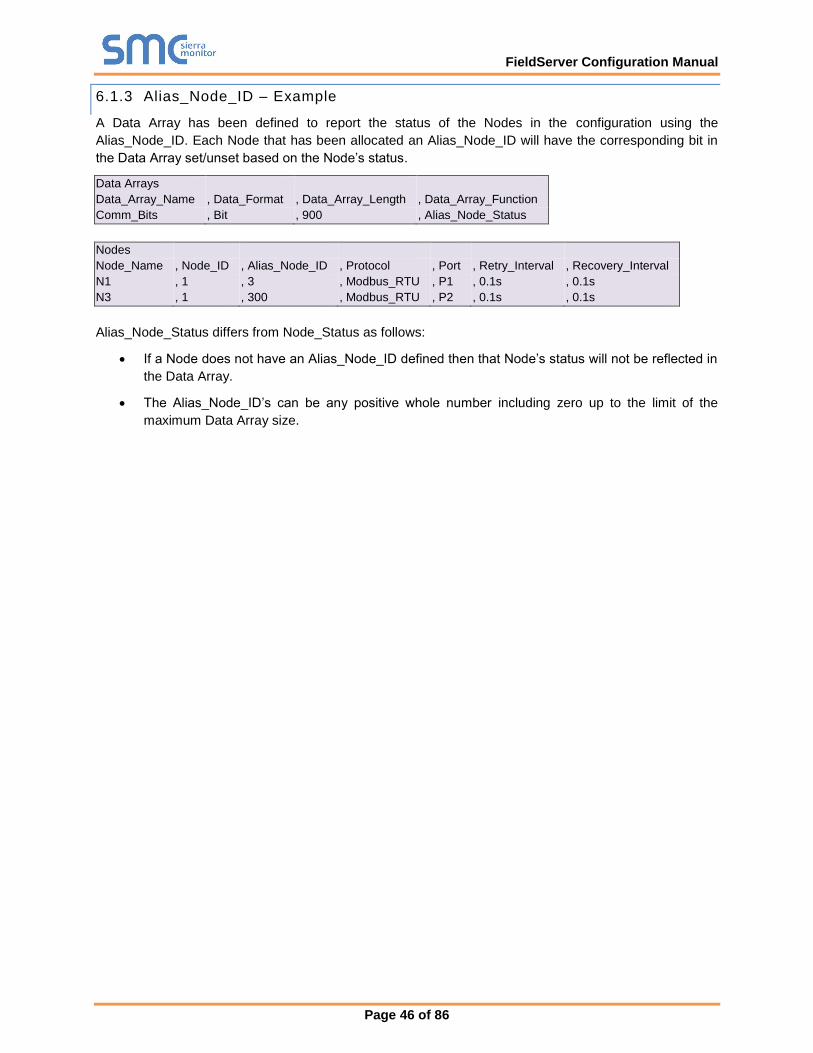
FieldServer Configuration Manual
Page 46 of 86
6.1.3 Alias_Node_ID – Example
A Data Array has been defined to report the status of the Nodes in the configuration using the
Alias_Node_ID. Each Node that has been allocated an Alias_Node_ID will have the corresponding bit in
the Data Array set/unset based on the Node’s status.
Data Arrays
Data_Array_Name , Data_Format , Data_Array_Length , Data_Array_Function
Comm_Bits , Bit , 900 , Alias_Node_Status
Nodes
Node_Name , Node_ID , Alias_Node_ID , Protocol , Port , Retry_Interval , Recovery_Interval
N1 , 1 , 3 , Modbus_RTU , P1 , 0.1s , 0.1s
N3 , 1 , 300 , Modbus_RTU , P2 , 0.1s , 0.1s
Alias_Node_Status differs from Node_Status as follows:
• If a Node does not have an Alias_Node_ID defined then that Node’s status will not be reflected in
the Data Array.
• The Alias_Node_ID’s can be any positive whole number including zero up to the limit of the
maximum Data Array size.
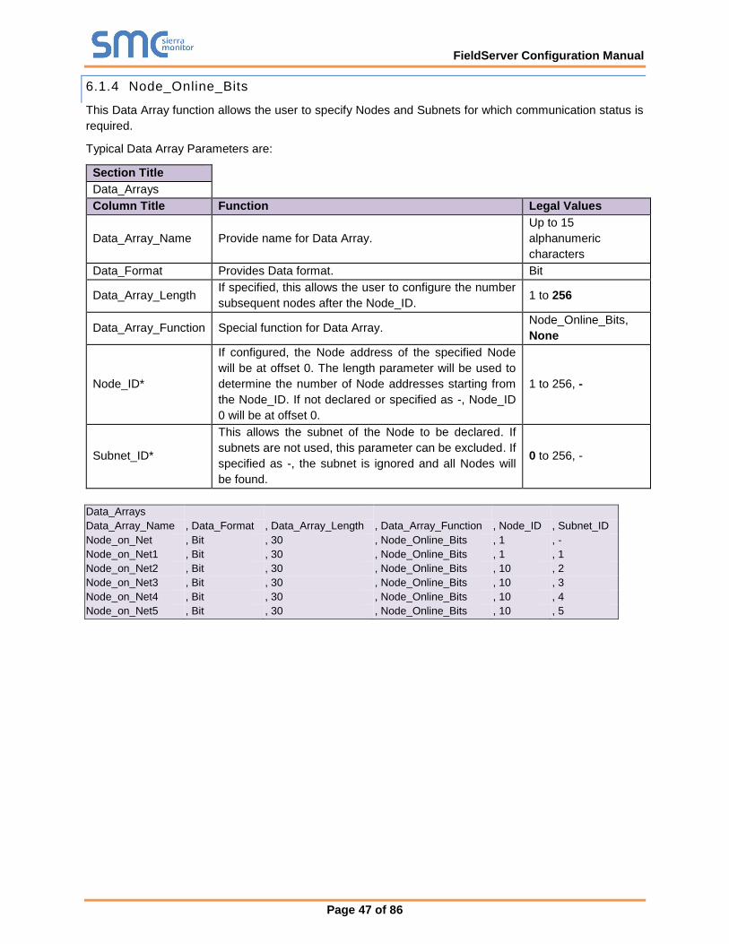
FieldServer Configuration Manual
Page 47 of 86
6.1.4 Node_Online_Bits
This Data Array function allows the user to specify Nodes and Subnets for which communication status is
required.
Typical Data Array Parameters are:
Section Title
Data_Arrays
Column Title Function Legal Values
Data_Array_Name Provide name for Data Array.
Up to 15
alphanumeric
characters
Data_Format Provides Data format. Bit
Data_Array_Length If specified, this allows the user to configure the number
subsequent nodes after the Node_ID. 1 to 256
Data_Array_Function Special function for Data Array. Node_Online_Bits,
None
Node_ID*
If configured, the Node address of the specified Node
will be at offset 0. The length parameter will be used to
determine the number of Node addresses starting from
the Node_ID. If not declared or specified as -, Node_ID
0 will be at offset 0.
1 to 256, -
Subnet_ID*
This allows the subnet of the Node to be declared. If
subnets are not used, this parameter can be excluded. If
specified as -, the subnet is ignored and all Nodes will
be found.
0 to 256, -
Data_Arrays
Data_Array_Name , Data_Format , Data_Array_Length , Data_Array_Function , Node_ID , Subnet_ID
Node_on_Net , Bit , 30 , Node_Online_Bits , 1 , -
Node_on_Net1 , Bit , 30 , Node_Online_Bits , 1 , 1
Node_on_Net2 , Bit , 30 , Node_Online_Bits , 10 , 2
Node_on_Net3 , Bit , 30 , Node_Online_Bits , 10 , 3
Node_on_Net4 , Bit , 30 , Node_Online_Bits , 10 , 4
Node_on_Net5 , Bit , 30 , Node_Online_Bits , 10 , 5
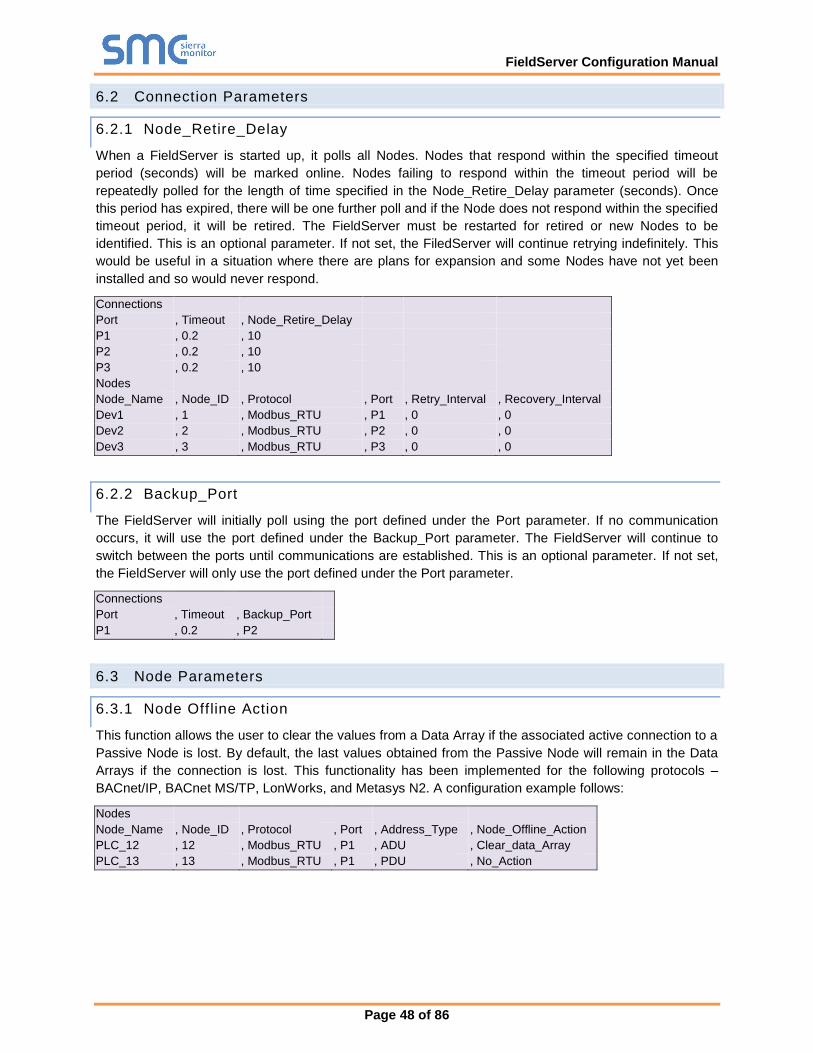
FieldServer Configuration Manual
Page 48 of 86
6.2 Connection Parameters
6.2.1 Node_Retire_Delay
When a FieldServer is started up, it polls all Nodes. Nodes that respond within the specified timeout
period (seconds) will be marked online. Nodes failing to respond within the timeout period will be
repeatedly polled for the length of time specified in the Node_Retire_Delay parameter (seconds). Once
this period has expired, there will be one further poll and if the Node does not respond within the specified
timeout period, it will be retired. The FieldServer must be restarted for retired or new Nodes to be
identified. This is an optional parameter. If not set, the FiledServer will continue retrying indefinitely. This
would be useful in a situation where there are plans for expansion and some Nodes have not yet been
installed and so would never respond.
Connections
Port , Timeout , Node_Retire_Delay
P1 , 0.2 , 10
P2 , 0.2 , 10
P3 , 0.2 , 10
Nodes
Node_Name , Node_ID , Protocol , Port , Retry_Interval , Recovery_Interval
Dev1 , 1 , Modbus_RTU , P1 , 0 , 0
Dev2 , 2 , Modbus_RTU , P2 , 0 , 0
Dev3 , 3 , Modbus_RTU , P3 , 0 , 0
6.2.2 Backup_Port
The FieldServer will initially poll using the port defined under the Port parameter. If no communication
occurs, it will use the port defined under the Backup_Port parameter. The FieldServer will continue to
switch between the ports until communications are established. This is an optional parameter. If not set,
the FieldServer will only use the port defined under the Port parameter.
Connections
Port , Timeout , Backup_Port
P1 , 0.2 , P2
6.3 Node Parameters
6.3.1 Node Offline Action
This function allows the user to clear the values from a Data Array if the associated active connection to a
Passive Node is lost. By default, the last values obtained from the Passive Node will remain in the Data
Arrays if the connection is lost. This functionality has been implemented for the following protocols –
BACnet/IP, BACnet MS/TP, LonWorks, and Metasys N2. A configuration example follows:
Nodes
Node_Name , Node_ID , Protocol , Port , Address_Type , Node_Offline_Action
PLC_12 , 12 , Modbus_RTU , P1 , ADU , Clear_data_Array
PLC_13 , 13 , Modbus_RTU , P1 , PDU , No_Action
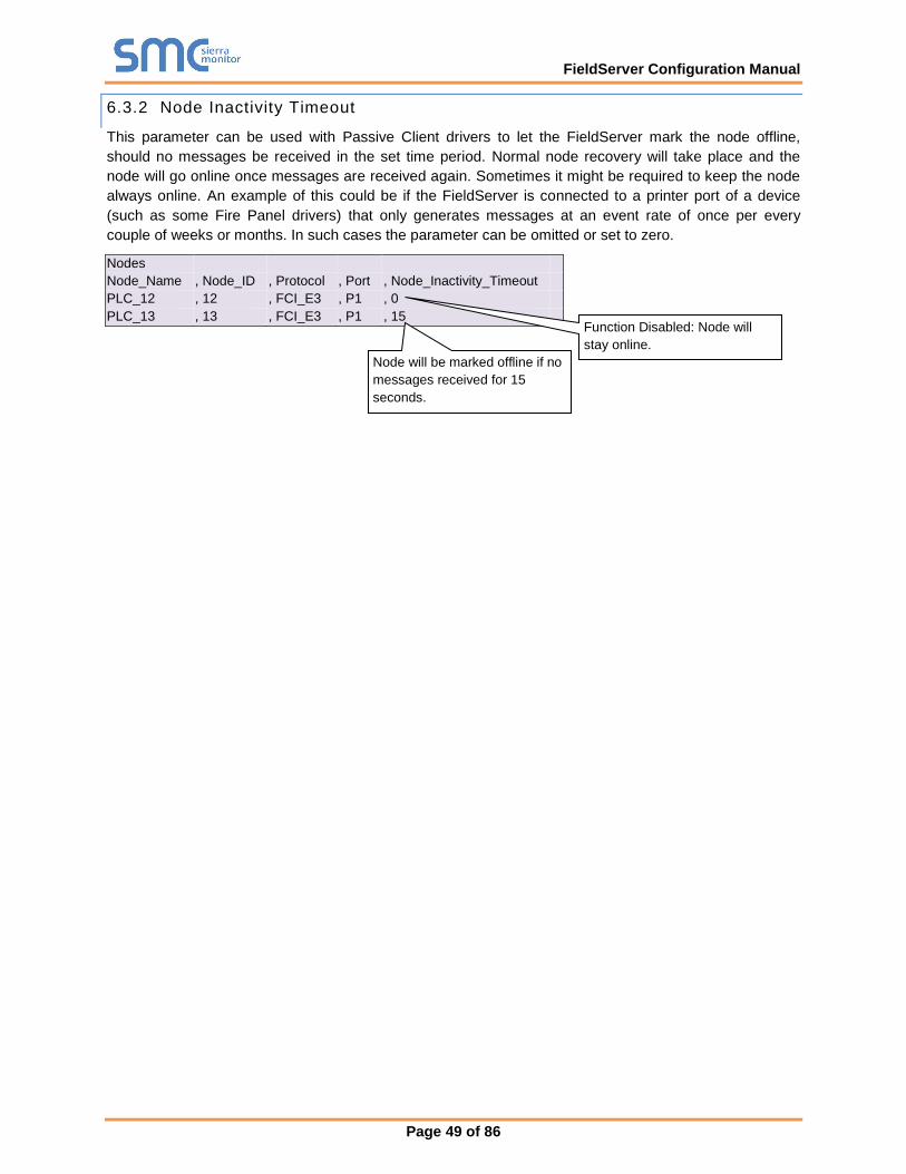
FieldServer Configuration Manual
Page 49 of 86
6.3.2 Node Inactivity Timeout
This parameter can be used with Passive Client drivers to let the FieldServer mark the node offline,
should no messages be received in the set time period. Normal node recovery will take place and the
node will go online once messages are received again. Sometimes it might be required to keep the node
always online. An example of this could be if the FieldServer is connected to a printer port of a device
(such as some Fire Panel drivers) that only generates messages at an event rate of once per every
couple of weeks or months. In such cases the parameter can be omitted or set to zero.
Nodes
Node_Name , Node_ID , Protocol , Port , Node_Inactivity_Timeout
PLC_12 , 12 , FCI_E3 , P1 , 0
PLC_13 , 13 , FCI_E3 , P1 , 15
Node will be marked offline if no
messages received for 15
seconds.
Function Disabled: Node will
stay online.
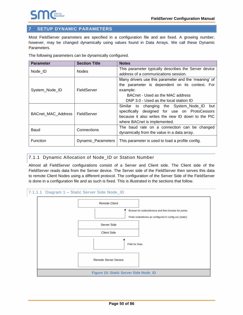
FieldServer Configuration Manual
Page 50 of 86
7 SETUP DYNAMIC PARAMETERS
Most FieldServer parameters are specified in a configuration file and are fixed. A growing number,
however, may be changed dynamically using values found in Data Arrays. We call these Dynamic
Parameters.
The following parameters can be dynamically configured.
Parameter Section Title Notes
Node_ID Nodes This parameter typically describes the Server device
address of a communications session.
System_Node_ID FieldServer
Many drivers use this parameter and the ‘meaning’ of
the parameter is dependent on its context. For
example:
BACnet - Used as the MAC address
DNP 3.0 - Used as the local station ID
BACnet_MAC_Address FieldServer
Similar to changing the System_Node_ID but
specifically designed for use on ProtoCessors
because it also writes the new ID down to the PIC
where BACnet is implemented.
Baud Connections The baud rate on a connection can be changed
dynamically from the value in a data array.
Function Dynamic_Parameters This parameter is used to load a profile config.
7.1.1 Dynamic Allocation of Node_ID or Station Number
Almost all FieldServer configurations consist of a Server and Client side. The Client side of the
FieldServer reads data from the Server device. The Server side of the FieldServer then serves this data
to remote Client Nodes using a different protocol. The configuration of the Server Side of the FieldServer
is done in a configuration file and as such is fixed. This is illustrated in the sections that follow.
7.1.1.1 Diagram 1 – Static Server Side Node_ID
Remote Client
Remote Server Device
Client Side
Server Side
Browse for nodes/devices and then browse for points.
Polls for Data
Finds node/device as configured in config.csv (static)
Figure 10: Static Server Side Node_ID
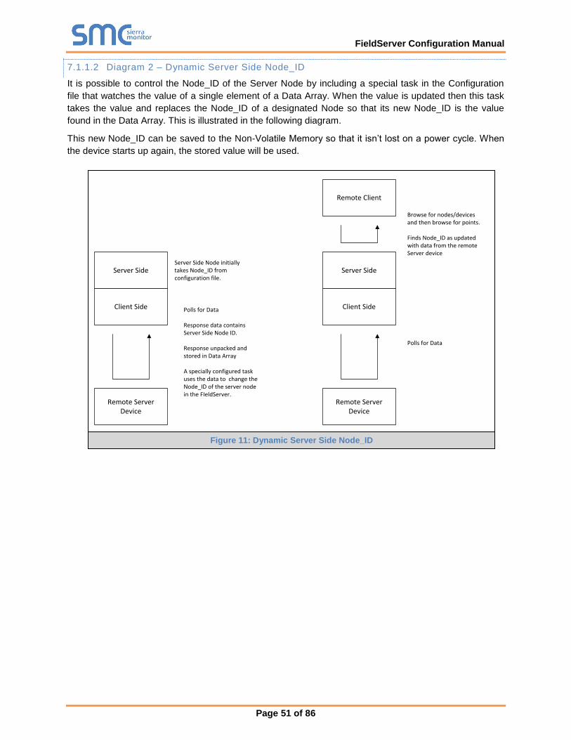
FieldServer Configuration Manual
Page 51 of 86
7.1.1.2 Diagram 2 – Dynamic Server Side Node_ID
It is possible to control the Node_ID of the Server Node by including a special task in the Configuration
file that watches the value of a single element of a Data Array. When the value is updated then this task
takes the value and replaces the Node_ID of a designated Node so that its new Node_ID is the value
found in the Data Array. This is illustrated in the following diagram.
This new Node_ID can be saved to the Non-Volatile Memory so that it isn’t lost on a power cycle. When
the device starts up again, the stored value will be used.
Remote Server Device
Client Side
Server Side
Polls for Data
Response data contains Server Side Node ID.
Response unpacked and stored in Data Array
A specially configured task uses the data to change the Node_ID of the server node in the FIeldServer.
Remote Client
Remote Server Device
Client Side
Server Side
Browse for nodes/devices and then browse for points.
Finds Node_ID as updated with data from the remote Server device
Polls for Data
Server Side Node initially takes Node_ID from configuration file.
Figure 11: Dynamic Server Side Node_ID
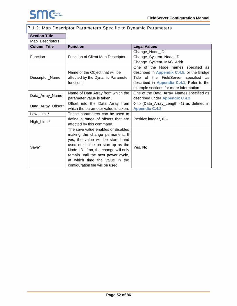
FieldServer Configuration Manual
Page 52 of 86
7.1.2 Map Descriptor Parameters Specific to Dynamic Parameters
Section Title
Map_Descriptors
Column Title Function Legal Values
Function Function of Client Map Descriptor.
Change_Node_ID
Change_System_Node_ID
Change_System_MAC_Addr
Descriptor_Name
Name of the Object that will be
affected by the Dynamic Parameter
function.
One of the Node names specified as
described in Appendix C.4.5, or the Bridge
Title of the FieldServer specified as
described in Appendix C.4.1; Refer to the
example sections for more information
Data_Array_Name Name of Data Array from which the
parameter value is taken.
One of the Data_Array_Names specified as
described under Appendix C.4.2
Data_Array_Offset* Offset into the Data Array from
which the parameter value is taken.
0 to (Data_Array_Length -1) as defined in
Appendix C.4.2
Low_Limit* These parameters can be used to
define a range of offsets that are
affected by this command.
Positive integer, 0, - High_Limit*
Save*
The save value enables or disables
making the change permanent. If
yes, the value will be stored and
used next time on start-up as the
Node_ID. If no, the change will only
remain until the next power cycle,
at which time the value in the
configuration file will be used.
Yes, No
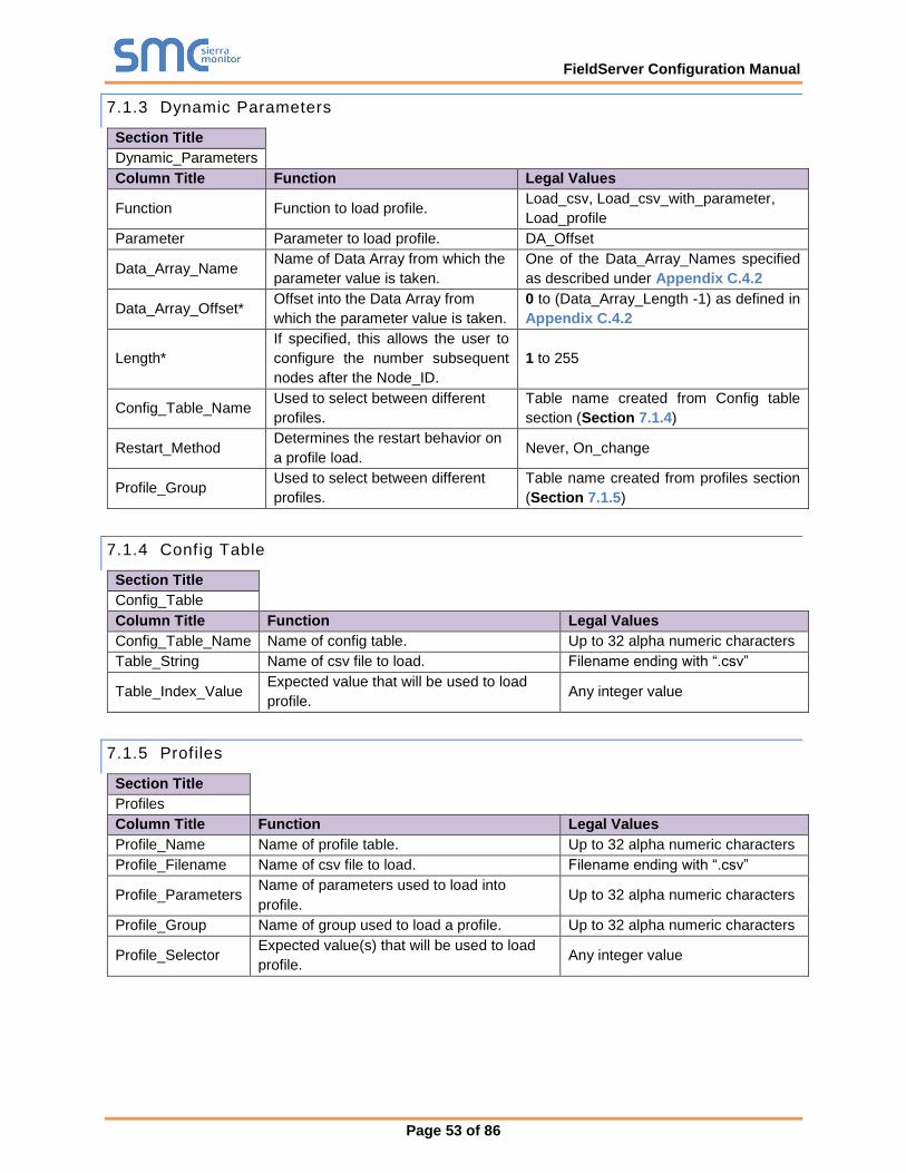
FieldServer Configuration Manual
Page 53 of 86
7.1.3 Dynamic Parameters
Section Title
Dynamic_Parameters
Column Title Function Legal Values
Function Function to load profile. Load_csv, Load_csv_with_parameter,
Load_profile
Parameter Parameter to load profile. DA_Offset
Data_Array_Name Name of Data Array from which the
parameter value is taken.
One of the Data_Array_Names specified
as described under Appendix C.4.2
Data_Array_Offset* Offset into the Data Array from
which the parameter value is taken.
0 to (Data_Array_Length -1) as defined in
Appendix C.4.2
Length*
If specified, this allows the user to
configure the number subsequent
nodes after the Node_ID.
1 to 255
Config_Table_Name Used to select between different
profiles.
Table name created from Config table
section (Section 7.1.4)
Restart_Method Determines the restart behavior on
a profile load. Never, On_change
Profile_Group Used to select between different
profiles.
Table name created from profiles section
(Section 7.1.5)
7.1.4 Config Table
Section Title
Config_Table
Column Title Function Legal Values
Config_Table_Name Name of config table. Up to 32 alpha numeric characters
Table_String Name of csv file to load. Filename ending with “.csv”
Table_Index_Value Expected value that will be used to load
profile. Any integer value
7.1.5 Profiles
Section Title
Profiles
Column Title Function Legal Values
Profile_Name Name of profile table. Up to 32 alpha numeric characters
Profile_Filename Name of csv file to load. Filename ending with “.csv”
Profile_Parameters Name of parameters used to load into
profile. Up to 32 alpha numeric characters
Profile_Group Name of group used to load a profile. Up to 32 alpha numeric characters
Profile_Selector Expected value(s) that will be used to load
profile. Any integer value
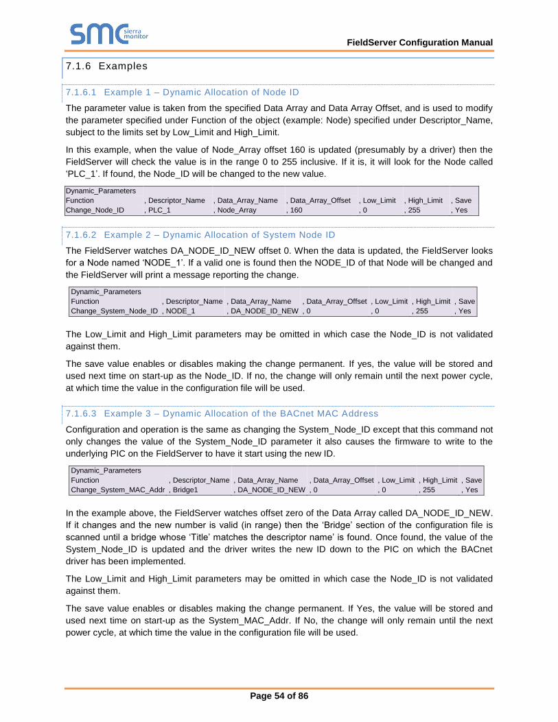
FieldServer Configuration Manual
Page 54 of 86
7.1.6 Examples
7.1.6.1 Example 1 – Dynamic Allocation of Node ID
The parameter value is taken from the specified Data Array and Data Array Offset, and is used to modify
the parameter specified under Function of the object (example: Node) specified under Descriptor_Name,
subject to the limits set by Low_Limit and High_Limit.
In this example, when the value of Node_Array offset 160 is updated (presumably by a driver) then the
FieldServer will check the value is in the range 0 to 255 inclusive. If it is, it will look for the Node called
‘PLC_1’. If found, the Node_ID will be changed to the new value.
Dynamic_Parameters
Function , Descriptor_Name , Data_Array_Name , Data_Array_Offset , Low_Limit , High_Limit , Save
Change_Node_ID , PLC_1 , Node_Array , 160 , 0 , 255 , Yes
7.1.6.2 Example 2 – Dynamic Allocation of System Node ID
The FieldServer watches DA_NODE_ID_NEW offset 0. When the data is updated, the FieldServer looks
for a Node named ‘NODE_1’. If a valid one is found then the NODE_ID of that Node will be changed and
the FieldServer will print a message reporting the change.
Dynamic_Parameters
Function , Descriptor_Name , Data_Array_Name , Data_Array_Offset , Low_Limit , High_Limit , Save
Change_System_Node_ID , NODE_1 , DA_NODE_ID_NEW , 0 , 0 , 255 , Yes
The Low_Limit and High_Limit parameters may be omitted in which case the Node_ID is not validated
against them.
The save value enables or disables making the change permanent. If yes, the value will be stored and
used next time on start-up as the Node_ID. If no, the change will only remain until the next power cycle,
at which time the value in the configuration file will be used.
7.1.6.3 Example 3 – Dynamic Allocation of the BACnet MAC Address
Configuration and operation is the same as changing the System_Node_ID except that this command not
only changes the value of the System_Node_ID parameter it also causes the firmware to write to the
underlying PIC on the FieldServer to have it start using the new ID.
Dynamic_Parameters
Function , Descriptor_Name , Data_Array_Name , Data_Array_Offset , Low_Limit , High_Limit , Save
Change_System_MAC_Addr , Bridge1 , DA_NODE_ID_NEW , 0 , 0 , 255 , Yes
In the example above, the FieldServer watches offset zero of the Data Array called DA_NODE_ID_NEW.
If it changes and the new number is valid (in range) then the ‘Bridge’ section of the configuration file is
scanned until a bridge whose ‘Title’ matches the descriptor name’ is found. Once found, the value of the
System_Node_ID is updated and the driver writes the new ID down to the PIC on which the BACnet
driver has been implemented.
The Low_Limit and High_Limit parameters may be omitted in which case the Node_ID is not validated
against them.
The save value enables or disables making the change permanent. If Yes, the value will be stored and
used next time on start-up as the System_MAC_Addr. If No, the change will only remain until the next
power cycle, at which time the value in the configuration file will be used.

FieldServer Configuration Manual
Page 55 of 86
7.1.6.4 Example 4 – Dynamic Allocation of the Connection Baud Rate
The Baud Rate on a connection can be dynamically changed from a Data Array Value by one of the
following methods.
Method 1: Using pre-mapped Data Array values to Baud Rates
By defining the Data Array format as Baud, a responsible Map Descriptor can be used to dynamically
change the Baud Rate on the associated connection. In the Example the below the Baud Rate on the R1
connection will be set to 9600 at startup, and will be changed to one of the following Baud Rates (if
supported) whenever the Map Descriptor stores a value in the Data Array.
Data Array Value Baud Rate
0 Default
1 110
2 300
3 600
4 1200
5 2400
6 4800
7 9600
8 19200
9 20833
10 28800
11 38400
12 57600
13 76800
14 115200
Specify the Data Format as Baud. This forces the use of the Values/Baud Rate table above.
Data_Arrays Data_Array_Name , Data_Format , Data_Array_Length DA_BAUD , BAUD , 1
The Connection, Node and Map Descriptor examples below apply to both methods.
Connections Port , Baud , Parity , Data_Bits , Stop_Bits , Protocol R1 , 9600 , None , 8 , 1 , Modbus_RTU
Node_Name , Node_ID , Protocol , Port MB_RTU , 11 , Modbus_RTU , R1
Map_Descriptors Map_Descriptor_Name , Scan_Interval , Data_Array_Name , Data_Array_Offset , Function , Node_Name , Address , Length CMD_AO1 , 1.0s , DA_BAUD , 0 , RDBC , MB_RTU , 40001 , 1
Method 2: Using actual Baud Rate Values
Specify the Data Format as a conventional value data type (for example - Byte, Uint16, Uint32)
Data_Arrays Data_Array_Name , Data_Format , Data_Array_Length DA_BAUD , UINT32 , 1
Only for this method, specify a dynamic parameter of Function Baud_Rate to allow the use of actual Baud
Rate values in the Data Array to change the Baud Rate Dynamically stored in the Data Array will cause
the Baud Rate to be changed.
Dynamic_Parameters
Function , Descriptor_Name , Data_Array_Name , Data_Array_offset
Baud_Rate , R1 , DA_BAUD , 0

FieldServer Configuration Manual
Page 56 of 86
7.1.7 Error Messages
Message Description
DynParam:#1 Err. Validation
impossible. Lo=%f Hi=%f
Desc=%s"
The low validation value is greater than the high value.8
DynParam:#2 Err.
DescName=%s too long.
This message is printed when evaluating a Dynamic parameters task
where the function = ‘Change_Node_ID’. The maximum length of the
descriptor is 32 characters.8
DynParam:#3 Err. Node_ID
Set from DA. Node=%s not
found
While trying to change the Node_ID, the FieldServer could not find a
Node whose name matches the task’s ‘Descriptor_Name’ parameter.8
DynParam:#4 Err. Node_ID
Validation failed. Lo=%ld
Hi=%ld Rqd=%d Node=%s
The Node_ID was not changed because the dynamic value extracted
from a DA did not satisfy the validation. Check that the devices have
been correctly configured. Possibly mapping of DA and offset need
adjustment.
DynParam:#5 FYI. Node=%s
Id=%d changed to %d
(%s:%d=DA:off)
This message is printed each time the Node_ID is successfully updated
dynamically. You may ignore this message if it confirms your
expectations.
DynParam:#6 Err.
DescName=%s too long.
This message is printed when evaluating a Dynamic parameters task
where the function = ‘Change_System_Node_ID’ or
‘Change_System_MAC_Add’. The maximum length of the descriptor is
32 characters.8
DynParam:#7 Err.
System_Node_Id Validtn
failed. Lo=%ld Hi=%ld
Rqd=%d Node=%s
The value extracted from the DA to be used as a dynamic parameter is
out of range (based on the low and high values specified). Review the
validation range in the configuration file and also review your mapping.
Perhaps the DA:offset does not contain the new ID.
DynParam:#8 FYI.
Bridge=%s(%d) Id=%d
changed to %d
(%s:%d=DA:off)
This is confirmation of a change of a symnica parameter where the
function is ‘Change_System_Node_ID’ or ‘Change_System_MAC_Add’.
You may ignore this message if it confirms your expectations.
DynParam:#9 FYI. Cant write
MAC_ADDR to PIC with this
firmware
This message will be printed immediately after #8. If the platform is not
a ProtoCessor, it can be ignored.
8 Edit the configuration, download the modified configuration and reset the FieldServer for the changes to take effect.

FieldServer Configuration Manual
Page 57 of 86
8 PORT EXPANDER MODE – PEX MODE
Under certain conditions the FieldServer can be configured in a Port Expander Mode where statically
configured Map Descriptors are not required to retrieve data from a Server Node.
8.1 How Port Expansion Works
When the FieldServer receives a poll from the Client Node, it scans its internal tables looking for a Map
Descriptor that matches the poll. If such a Map Descriptor is found, the FieldServer responds with data
from the appropriate Data Array. If no Map Descriptor is found, the FieldServer scans the list of
configured Nodes and creates a Map Descriptor (cache) to fetch the data from that Node and returns this
data to the Client. The FieldServer will continue to retrieve data from the Node for future polls from the
Client Node. If the Client Node does not access the data for longer than the time configured under
Cache_Time_To_Live, (refer to Appendix C.4) then the FieldServer will stop reading the data and
remove the Map Descriptor (cache).
8.2 Advantages of Port Expander Mode
Configuration is simpler - the FieldServer automatically creates and deletes Map Descriptors as required.
If mapping changes are made to a Client, the FieldServer usually does not need to be reconfigured.
8.3 Limitations of Port Expander Mode
Port Expander Mode does not work with all combinations of drivers.
If the FieldServer is used as a Pure Port Expander (Single Protocol) there is no restriction at all (such as
Modbus RTU Port Expander).
The following families of drivers support Port Expansion within the family:
• Modbus RTU
8.4 Port Expander Write Options
Three possible scenarios exist for Writes in Port Expansion Mode:
• A Temporary Read Map Descriptor already exists for the point being written.
• A Temporary Write Map Descriptor already exists for the point being written.
• No Temporary Map Descriptor exists for the point being written.
In the first two cases data is simply written through the FieldServer to the Server using the existing
Temporary Data Arrays. In the third case, temporary Map Descriptors are created.
The Node parameter Write_Ack_Option needs to be configured. By default, the FieldServer will wait for a
write to complete before sending an acknowledgement of a write. However, it is possible to configure the
FieldServer to send acknowledgement of the write when the write is received and not wait for upstream
device to acknowledge it. Refer to Appendix C.4.
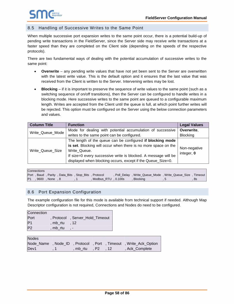
FieldServer Configuration Manual
Page 58 of 86
8.5 Handling of Successive Writes to the Same Point
When multiple successive port expansion writes to the same point occur, there is a potential build-up of
pending write transactions in the FieldServer, since the Server side may receive write transactions at a
faster speed than they are completed on the Client side (depending on the speeds of the respective
protocols).
There are two fundamental ways of dealing with the potential accumulation of successive writes to the
same point:
• Overwrite – any pending write values that have not yet been sent to the Server are overwritten
with the latest write value. This is the default option and it ensures that the last value that was
received from the Client is written to the Server. Intervening writes may be lost.
• Blocking – if it is important to preserve the sequence of write values to the same point (such as a
switching sequence of on/off transitions), then the Server can be configured to handle writes in a
blocking mode. Here successive writes to the same point are queued to a configurable maximum
length. Writes are accepted from the Client until the queue is full, at which point further writes will
be rejected. This option must be configured on the Server using the below connection parameters
and values.
Column Title Function Legal Values
Write_Queue_Mode Mode for dealing with potential accumulation of successive
writes to the same point can be configured.
Overwrite,
Blocking
Write_Queue_Size
The length of the queue can be configured if blocking mode
is set. Blocking will occur when there is no more space on the
Write_Queue.
If size=0 every successive write is blocked. A message will be
displayed when blocking occurs, except if the Queue_Size=0.
Non-negative
integer, 0
Connections
Port , Baud , Parity , Data_Bits , Stop_Bits , Protocol , Poll_Delay , Write_Queue_Mode , Write_Queue_Size , Timeout
P1 , 9600 , None , 8 , 1 , Modbus_RTU , 0.100s , Blocking , 5 , 8s
8.6 Port Expansion Configuration
The example configuration file for this mode is available from technical support if needed. Although Map
Descriptor configuration is not required, Connections and Nodes do need to be configured.
Connection
Port , Protocol , Server_Hold_Timeout
P1 , mb_rtu , 12
P2 , mb_rtu , -
Nodes
Node_Name , Node_ID , Protocol , Port , Timeout , Write_Ack_Option
Dev1 , 1 , mb_rtu , P2 , 12 , Ack_Complete

FieldServer Configuration Manual
Page 59 of 86
9 TIMING PARAMETERS
Under normal operation, the FieldServer will send a poll request to a Server device and that device will
reply with a response. The amount of time between successive poll requests is called the Scan_Interval.
The time between receiving a response from a Server device and the next poll request is called the
Poll_Delay.
If the FieldServer sends a poll request, and the Server device does not send a response, it is considered
a timeout. The time the FieldServer waits before declaring a timeout can be adjusted by the Timeout
parameter. If a timeout occurs, then the FieldServer will retry the poll request (number of times retried is
specified by the retries parameter). The interval between Retries is specified by the Retry_Interval. The
FieldServer will send poll requests at the end of each Retry_Interval. Once the specified numbers of
Retries have been sent, the FieldServer will mark the Node offline. Once a Node has been marked
offline, it will wait for a period specified by Recovery_Interval before sending another poll request.
Once the communications have been re-established, the FieldServer will wait for a period called
Probation_Delay, before marking the Node as online.
NOTE: The Ic_Timeout parameter monitors the time between characters in a response. If the time
exceeds the Ic_Timeout, the response is discarded and is considered a Timeout.
NOTE: All parameters in bold above are configurable. See table below for where they are configured,
and what the defaults will be if they are not configured. Refer also to Appendix C.2.
Parameter Default Value Where Used
Scan_Interval 2 seconds Map Descriptor, Node, Connection
Poll_Delay 0.05 seconds Connection
Timeout 2 seconds Map Descriptor, Node, Connection
Retry_Interval 10 seconds Node
Retries 3 times Node
Recovery_Interval 30 seconds Node
Probation_Delay 1 minute Node
Ic_Timeout 0.5 seconds Map Descriptor, Node, Connection
Node_Inactivity_Timeout 0 seconds Node (see Section 6.3.2)
NOTE: In the case of parameters that may be declared at the Connection, Node or Map Descriptor level,
when the parameter is declared at more than one level, the Map Descriptor declaration takes
highest priority, followed by the Node declaration and then the Connection declaration.
NOTE: A non-response from the remote Server device causes a Timeout. The driver does nothing until a
response is received or the timeout period has expired. Thus if a connection has two Nodes and
one Node is producing Timeouts this will have the effect of slowing down communication for the
other Node in the sense that the driver does nothing while the timeout timer is counting up to its
setpoint. Once there is a timeout on one Node, the driver will not retry any Map Descriptors on
that Node until the Retry_Interval has expired. Thus during the Retry_Interval the other Node will
get 100% of the service.
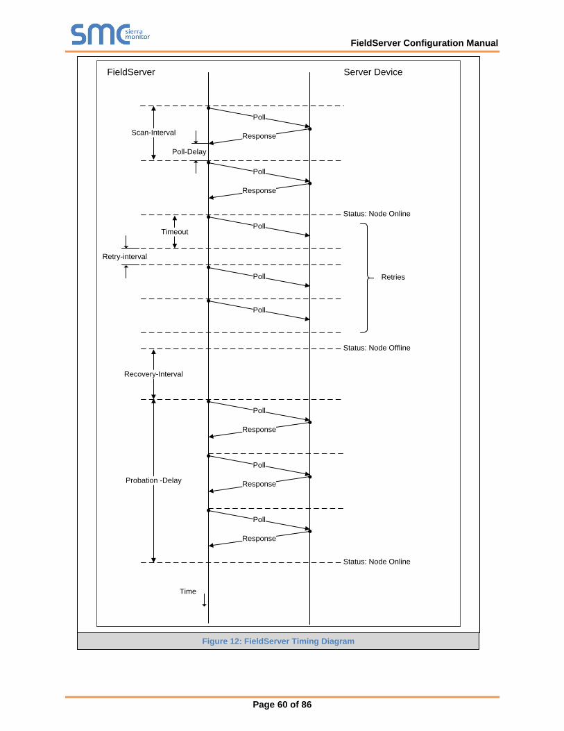
FieldServer Configuration Manual
Page 60 of 86
FieldServer Server Device
Poll
ResponseScan-Interval
Poll-Delay
Poll
Response
PollTimeout
Retry-interval
Poll
Poll
Recovery-Interval
Status: Node Online
Status: Node Offline
Poll
Response
Poll
Response
Poll
Response
Probation -Delay
Status: Node Online
Time
Retries
Figure 12: FieldServer Timing Diagram
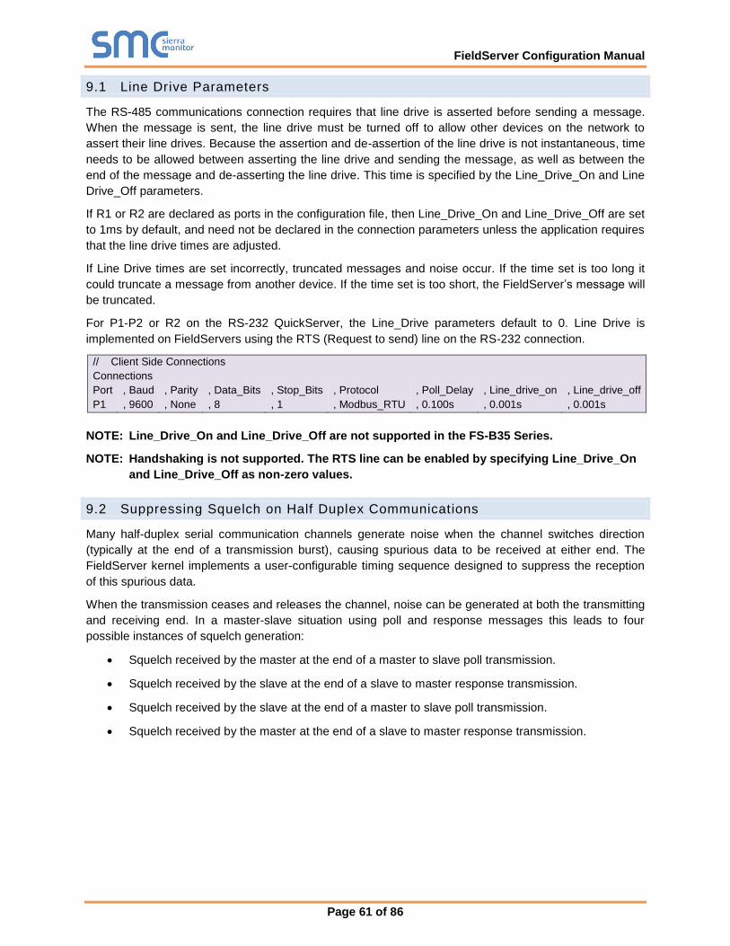
FieldServer Configuration Manual
Page 61 of 86
9.1 Line Drive Parameters
The RS-485 communications connection requires that line drive is asserted before sending a message.
When the message is sent, the line drive must be turned off to allow other devices on the network to
assert their line drives. Because the assertion and de-assertion of the line drive is not instantaneous, time
needs to be allowed between asserting the line drive and sending the message, as well as between the
end of the message and de-asserting the line drive. This time is specified by the Line_Drive_On and Line
Drive_Off parameters.
If R1 or R2 are declared as ports in the configuration file, then Line_Drive_On and Line_Drive_Off are set
to 1ms by default, and need not be declared in the connection parameters unless the application requires
that the line drive times are adjusted.
If Line Drive times are set incorrectly, truncated messages and noise occur. If the time set is too long it
could truncate a message from another device. If the time set is too short, the FieldServer’s message will
be truncated.
For P1-P2 or R2 on the RS-232 QuickServer, the Line_Drive parameters default to 0. Line Drive is
implemented on FieldServers using the RTS (Request to send) line on the RS-232 connection.
// Client Side Connections
Connections
Port , Baud , Parity , Data_Bits , Stop_Bits , Protocol , Poll_Delay , Line_drive_on , Line_drive_off
P1 , 9600 , None , 8 , 1 , Modbus_RTU , 0.100s , 0.001s , 0.001s
NOTE: Line_Drive_On and Line_Drive_Off are not supported in the FS-B35 Series.
NOTE: Handshaking is not supported. The RTS line can be enabled by specifying Line_Drive_On
and Line_Drive_Off as non-zero values.
9.2 Suppressing Squelch on Half Duplex Communications
Many half-duplex serial communication channels generate noise when the channel switches direction
(typically at the end of a transmission burst), causing spurious data to be received at either end. The
FieldServer kernel implements a user-configurable timing sequence designed to suppress the reception
of this spurious data.
When the transmission ceases and releases the channel, noise can be generated at both the transmitting
and receiving end. In a master-slave situation using poll and response messages this leads to four
possible instances of squelch generation:
• Squelch received by the master at the end of a master to slave poll transmission.
• Squelch received by the slave at the end of a slave to master response transmission.
• Squelch received by the slave at the end of a master to slave poll transmission.
• Squelch received by the master at the end of a slave to master response transmission.
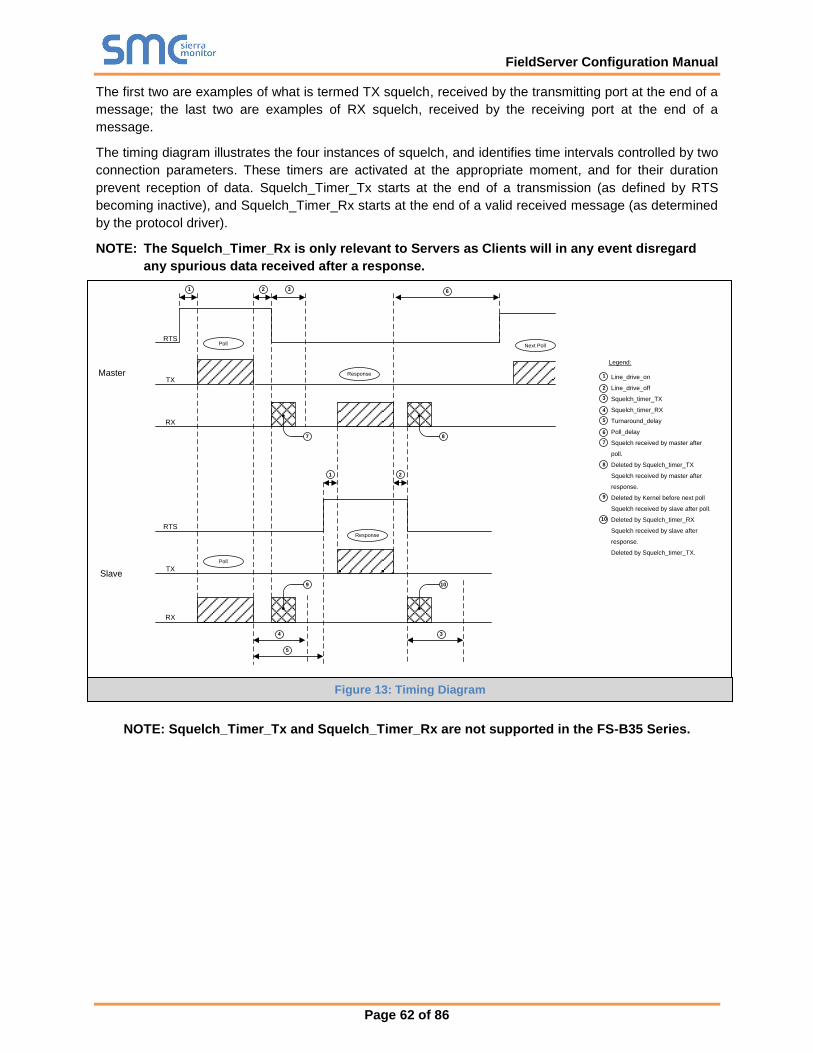
FieldServer Configuration Manual
Page 62 of 86
The first two are examples of what is termed TX squelch, received by the transmitting port at the end of a
message; the last two are examples of RX squelch, received by the receiving port at the end of a
message.
The timing diagram illustrates the four instances of squelch, and identifies time intervals controlled by two
connection parameters. These timers are activated at the appropriate moment, and for their duration
prevent reception of data. Squelch_Timer_Tx starts at the end of a transmission (as defined by RTS
becoming inactive), and Squelch_Timer_Rx starts at the end of a valid received message (as determined
by the protocol driver).
NOTE: The Squelch_Timer_Rx is only relevant to Servers as Clients will in any event disregard
any spurious data received after a response.
Master
Slave
Legend:
Line_drive_on
Line_drive_off
Squelch_timer_TX
Squelch_timer_RX
Turnaround_delay
Poll_delay
Squelch received by master after
poll.
Deleted by Squelch_timer_TX
Squelch received by master after
response.
Deleted by Kernel before next poll
Squelch received by slave after poll.
Deleted by Squelch_timer_RX
Squelch received by slave after
response.
Deleted by Squelch_timer_TX.
10
9
8
7
6
5
4
3
2
1
RTS
TX
RX
RTS
TX
RX
6321
Next PollPoll
Poll
Response
Response
7 8
21
9 10
4
5
3
.
NOTE: Squelch_Timer_Tx and Squelch_Timer_Rx are not supported in the FS-B35 Series.
Figure 13: Timing Diagram
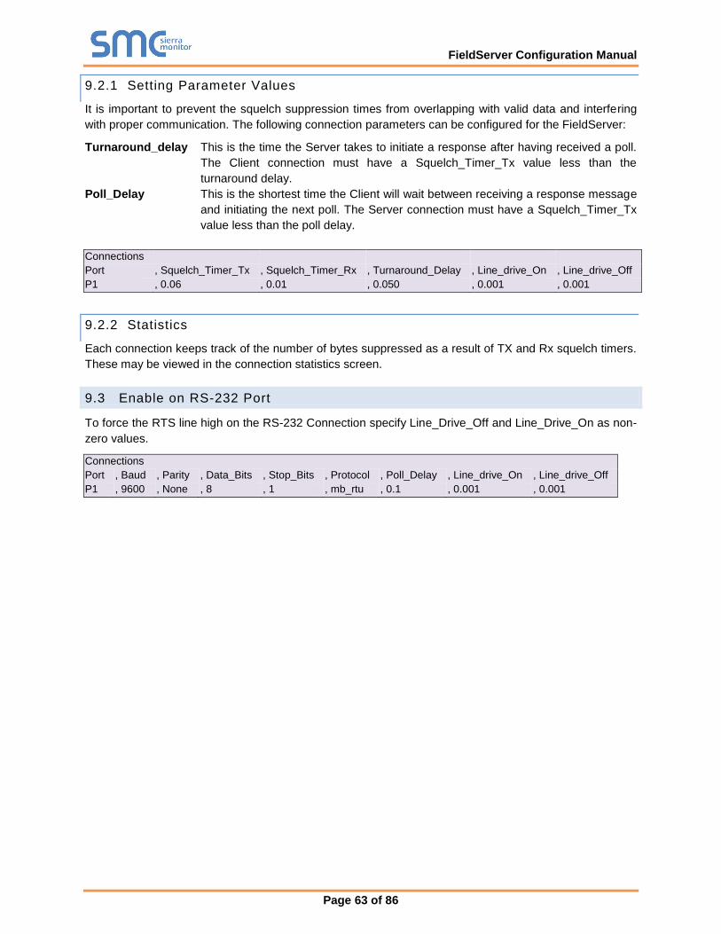
FieldServer Configuration Manual
Page 63 of 86
9.2.1 Setting Parameter Values
It is important to prevent the squelch suppression times from overlapping with valid data and interfering
with proper communication. The following connection parameters can be configured for the FieldServer:
Turnaround_delay This is the time the Server takes to initiate a response after having received a poll.
The Client connection must have a Squelch_Timer_Tx value less than the
turnaround delay.
Poll_Delay This is the shortest time the Client will wait between receiving a response message
and initiating the next poll. The Server connection must have a Squelch_Timer_Tx
value less than the poll delay.
Connections
Port , Squelch_Timer_Tx , Squelch_Timer_Rx , Turnaround_Delay , Line_drive_On , Line_drive_Off
P1 , 0.06 , 0.01 , 0.050 , 0.001 , 0.001
9.2.2 Statistics
Each connection keeps track of the number of bytes suppressed as a result of TX and Rx squelch timers.
These may be viewed in the connection statistics screen.
9.3 Enable on RS-232 Port
To force the RTS line high on the RS-232 Connection specify Line_Drive_Off and Line_Drive_On as non-
zero values.
Connections
Port , Baud , Parity , Data_Bits , Stop_Bits , Protocol , Poll_Delay , Line_drive_On , Line_drive_Off
P1 , 9600 , None , 8 , 1 , mb_rtu , 0.1 , 0.001 , 0.001
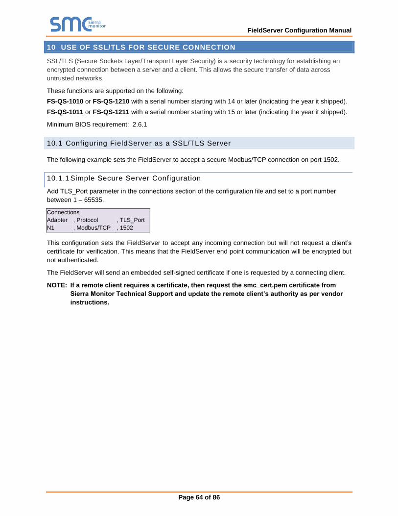
FieldServer Configuration Manual
Page 64 of 86
10 USE OF SSL/TLS FOR SECURE CONNECTION
SSL/TLS (Secure Sockets Layer/Transport Layer Security) is a security technology for establishing an
encrypted connection between a server and a client. This allows the secure transfer of data across
untrusted networks.
These functions are supported on the following:
FS-QS-1010 or FS-QS-1210 with a serial number starting with 14 or later (indicating the year it shipped).
FS-QS-1011 or FS-QS-1211 with a serial number starting with 15 or later (indicating the year it shipped).
Minimum BIOS requirement: 2.6.1
10.1 Configuring FieldServer as a SSL/TLS Server
The following example sets the FieldServer to accept a secure Modbus/TCP connection on port 1502.
10.1.1 Simple Secure Server Configuration
Add TLS_Port parameter in the connections section of the configuration file and set to a port number
between 1 – 65535.
Connections
Adapter , Protocol , TLS_Port
N1 , Modbus/TCP , 1502
This configuration sets the FieldServer to accept any incoming connection but will not request a client’s
certificate for verification. This means that the FieldServer end point communication will be encrypted but
not authenticated.
The FieldServer will send an embedded self-signed certificate if one is requested by a connecting client.
NOTE: If a remote client requires a certificate, then request the smc_cert.pem certificate from
Sierra Monitor Technical Support and update the remote client’s authority as per vendor
instructions.
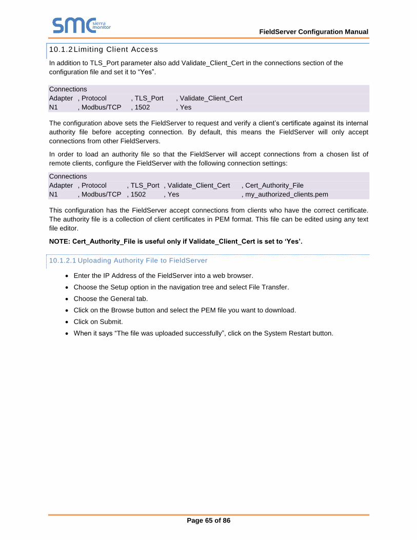
FieldServer Configuration Manual
Page 65 of 86
10.1.2 Limiting Client Access
In addition to TLS_Port parameter also add Validate_Client_Cert in the connections section of the
configuration file and set it to “Yes”.
Connections
Adapter , Protocol , TLS_Port , Validate_Client_Cert
N1 , Modbus/TCP , 1502 , Yes
The configuration above sets the FieldServer to request and verify a client’s certificate against its internal
authority file before accepting connection. By default, this means the FieldServer will only accept
connections from other FieldServers.
In order to load an authority file so that the FieldServer will accept connections from a chosen list of
remote clients, configure the FieldServer with the following connection settings:
Connections
Adapter , Protocol , TLS_Port , Validate_Client_Cert , Cert_Authority_File
N1 , Modbus/TCP , 1502 , Yes , my_authorized_clients.pem
This configuration has the FieldServer accept connections from clients who have the correct certificate.
The authority file is a collection of client certificates in PEM format. This file can be edited using any text
file editor.
NOTE: Cert_Authority_File is useful only if Validate_Client_Cert is set to ‘Yes’.
10.1.2.1 Uploading Authority File to FieldServer
• Enter the IP Address of the FieldServer into a web browser.
• Choose the Setup option in the navigation tree and select File Transfer.
• Choose the General tab.
• Click on the Browse button and select the PEM file you want to download.
• Click on Submit.
• When it says “The file was uploaded successfully”, click on the System Restart button.

FieldServer Configuration Manual
Page 66 of 86
10.1.3 Certif icate Validation Options
If connections must be limited to only a particular domain (vendor devices), include Check_Remote_Host
to specify the domain/host name.
Connections
Adapter , Protocol , TLS_Port , Validate_Client_Cert , Cert_Authority_File , Check_Remote_Host
N1 , Modbus/TCP , 1502 , Yes , my_authorized_clients.pem , SMC
The configuration above tells the FieldServer to only accept connections that have the correct certification
and is coming from the specified host.
The Check_Remote_Host value is synonymously known as common name, host name or domain etc.
The common name can be obtained by the following methods:
• Ask the certificate issuer for the host name.
• Use online tools to decode the certificate (for example: https://www.sslshopper.com/certificate-
decoder.html).
• If the program openssl is installed on the local PC, then run the following command to get the
common name: openssl x509 -in certificate.pem -text -noout
10.1.4 Set up Server Certif icate
Make sure the certificate is in PEM format. Otherwise, convert it to PEM format (reference the link below).
support.ssl.com/Knowledgebase/Article
Configure the FieldServer to use a custom certificate as shown below:
Connections
Adapter , Protocol , TLS_Port , Server_Cert_File
N1 , Modbus/TCP , 1502 , my_server_cert.pem
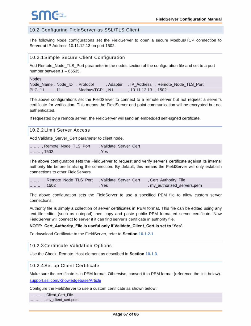
FieldServer Configuration Manual
Page 67 of 86
10.2 Configuring FieldServer as SSL/TLS Client
The following Node configurations set the FieldServer to open a secure Modbus/TCP connection to
Server at IP Address 10.11.12.13 on port 1502.
10.2.1 Simple Secure Client Configuration
Add Remote_Node_TLS_Port parameter in the nodes section of the configuration file and set to a port
number between 1 – 65535.
Nodes
Node_Name , Node_ID , Protocol , Adapter , IP_Address , Remote_Node_TLS_Port
PLC_11 , 11 , Modbus/TCP , N1 , 10.11.12.13 , 1502
The above configurations set the FieldServer to connect to a remote server but not request a server’s
certificate for verification. This means the FieldServer end point communication will be encrypted but not
authenticated.
If requested by a remote server, the FieldServer will send an embedded self-signed certificate.
10.2.2 Limit Server Access
Add Validate_Server_Cert parameter to client node.
……. , Remote_Node_TLS_Port , Validate_Server_Cert
…….. , 1502 , Yes
The above configuration sets the FieldServer to request and verify server’s certificate against its internal
authority file before finalizing the connection. By default, this means the FieldServer will only establish
connections to other FieldServers.
……. , Remote_Node_TLS_Port , Validate_Server_Cert , Cert_Authority_File
…….. , 1502 , Yes , my_authorized_servers.pem
The above configuration sets the FieldServer to use a specified PEM file to allow custom server
connections.
Authority file is simply a collection of server certificates in PEM format. This file can be edited using any
text file editor (such as notepad) then copy and paste public PEM formatted server certificate. Now
FieldServer will connect to server if it can find server’s certificate in authority file.
NOTE: Cert_Authority_File is useful only if Validate_Client_Cert is set to ‘Yes’.
To download Certificate to the FieldServer, refer to Section 10.1.2.1.
10.2.3 Certif icate Validation Options
Use the Check_Remote_Host element as described in Section 10.1.3.
10.2.4 Set up Client Certif icate
Make sure the certificate is in PEM format. Otherwise, convert it to PEM format (reference the link below).
support.ssl.com/Knowledgebase/Article
Configure the FieldServer to use a custom certificate as shown below:
……… , Client_Cert_File
……… , my_client_cert.pem

FieldServer Configuration Manual
Page 68 of 86
Appendix A. Useful Features
Using Comments
Configuration file comments are either lines or line segments that start with “//”. These allow notation
within the code for reference or organization. See Examples below.
Nodes // Main building Node
Node_Name , Node_ID , Protocol
Test_A , 1 , Modbus_RTU
Nodes // Main building Node
Node_Name , Node_ID , Protocol
Test_A , 1 , Modbus_RTU
NOTE: It is recommended to keep a good margin of space between the code and the comment
when you follow code with a comment on the same line. This prevents confusion.
However, never place comments in the middle of a segment of code. This will prevent the code from
running properly.
Nodes // Main building Node
Node_Name ,Node_ID , Protocol
Test_A , 1 , Modbus_RTU
Using Conditional Process Statements
The Client or Server sides of a configuration can be disabled using the following keywords:
Keyword Function
Ignore All lines will be ignored after this statement until a process statement is encountered.
Process Causes lines after this statement to be processed again.
End Configuration stops here, ignoring all further lines.
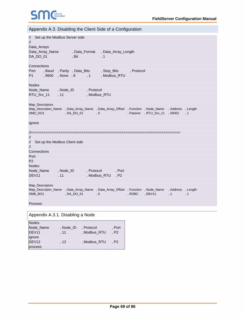
FieldServer Configuration Manual
Page 69 of 86
Disabling the Client Side of a Configuration
// Set up the Modbus Server side
//
Data_Arrays
Data_Array_Name , Data_Format , Data_Array_Length
DA_DO_01 , Bit , 1
Connections
Port , Baud , Parity , Data_Bits , Stop_Bits , Protocol
P1 , 9600 , None , 8 , 1 , Modbus_RTU
Nodes
Node_Name , Node_ID , Protocol
RTU_Srv_11 , 11 , Modbus_RTU
Map_Descriptors
Map_Descriptor_Name , Data_Array_Name , Data_Array_Offset , Function , Node_Name , Address , Length
SMD_DO1 , DA_DO_01 , 0 , Passive , RTU_Srv_11 , 00001 , 1
ignore
//=======================================================================
//
// Set up the Modbus Client side
//
Connections
Port
P2
Nodes
Node_Name , Node_ID , Protocol , Port
DEV11 , 11 , Modbus_RTU , P2
Map_Descriptors
Map_Descriptor_Name , Data_Array_Name , Data_Array_Offset , Function , Node_Name , Address , Length
SMB_BO1 , DA_DO_01 , 0 , RDBC , DEV11 , 1 , 1
Process
Appendix A.3.1. Disabling a Node
Nodes
Node_Name , Node_ID , Protocol , Port
DEV11 , 11 , Modbus_RTU , P2
ignore
DEV12 , 12 , Modbus_RTU , P2
process
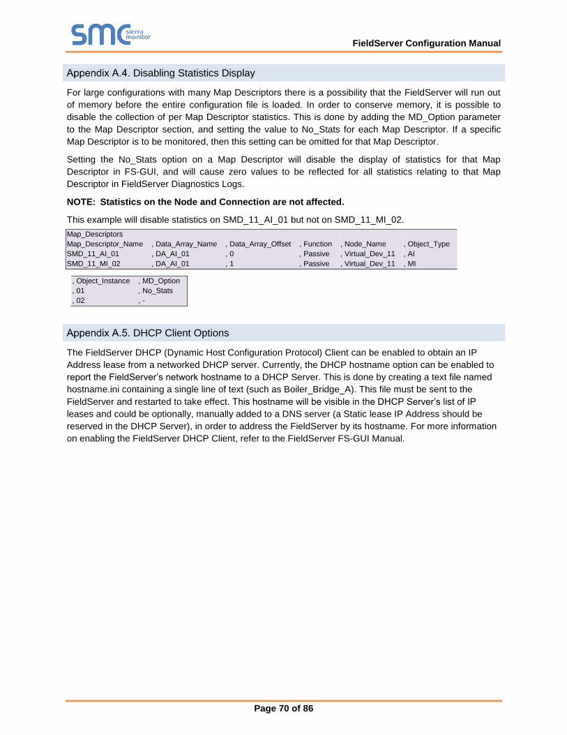
FieldServer Configuration Manual
Page 70 of 86
Disabling Statistics Display
For large configurations with many Map Descriptors there is a possibility that the FieldServer will run out
of memory before the entire configuration file is loaded. In order to conserve memory, it is possible to
disable the collection of per Map Descriptor statistics. This is done by adding the MD_Option parameter
to the Map Descriptor section, and setting the value to No_Stats for each Map Descriptor. If a specific
Map Descriptor is to be monitored, then this setting can be omitted for that Map Descriptor.
Setting the No_Stats option on a Map Descriptor will disable the display of statistics for that Map
Descriptor in FS-GUI, and will cause zero values to be reflected for all statistics relating to that Map
Descriptor in FieldServer Diagnostics Logs.
NOTE: Statistics on the Node and Connection are not affected.
This example will disable statistics on SMD_11_AI_01 but not on SMD_11_MI_02.
Map_Descriptors
Map_Descriptor_Name , Data_Array_Name , Data_Array_Offset , Function , Node_Name , Object_Type
SMD_11_AI_01 , DA_AI_01 , 0 , Passive , Virtual_Dev_11 , AI
SMD_11_MI_02 , DA_AI_01 , 1 , Passive , Virtual_Dev_11 , MI
, Object_Instance , MD_Option
, 01 , No_Stats
, 02 , -
DHCP Client Options
The FieldServer DHCP (Dynamic Host Configuration Protocol) Client can be enabled to obtain an IP
Address lease from a networked DHCP server. Currently, the DHCP hostname option can be enabled to
report the FieldServer’s network hostname to a DHCP Server. This is done by creating a text file named
hostname.ini containing a single line of text (such as Boiler_Bridge_A). This file must be sent to the
FieldServer and restarted to take effect. This hostname will be visible in the DHCP Server’s list of IP
leases and could be optionally, manually added to a DNS server (a Static lease IP Address should be
reserved in the DHCP Server), in order to address the FieldServer by its hostname. For more information
on enabling the FieldServer DHCP Client, refer to the FieldServer FS-GUI Manual.
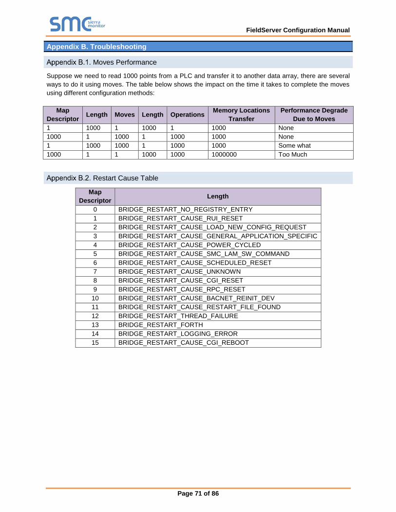
FieldServer Configuration Manual
Page 71 of 86
Appendix B. Troubleshooting
Moves Performance
Suppose we need to read 1000 points from a PLC and transfer it to another data array, there are several
ways to do it using moves. The table below shows the impact on the time it takes to complete the moves
using different configuration methods:
Map
Descriptor Length Moves Length Operations
Memory Locations
Transfer
Performance Degrade
Due to Moves
1 1000 1 1000 1 1000 None
1000 1 1000 1 1000 1000 None
1 1000 1000 1 1000 1000 Some what
1000 1 1 1000 1000 1000000 Too Much
Restart Cause Table
Map
Descriptor Length
0 BRIDGE_RESTART_NO_REGISTRY_ENTRY
1 BRIDGE_RESTART_CAUSE_RUI_RESET
2 BRIDGE_RESTART_CAUSE_LOAD_NEW_CONFIG_REQUEST
3 BRIDGE_RESTART_CAUSE_GENERAL_APPLICATION_SPECIFIC
4 BRIDGE_RESTART_CAUSE_POWER_CYCLED
5 BRIDGE_RESTART_CAUSE_SMC_LAM_SW_COMMAND
6 BRIDGE_RESTART_CAUSE_SCHEDULED_RESET
7 BRIDGE_RESTART_CAUSE_UNKNOWN
8 BRIDGE_RESTART_CAUSE_CGI_RESET
9 BRIDGE_RESTART_CAUSE_RPC_RESET
10 BRIDGE_RESTART_CAUSE_BACNET_REINIT_DEV
11 BRIDGE_RESTART_CAUSE_RESTART_FILE_FOUND
12 BRIDGE_RESTART_THREAD_FAILURE
13 BRIDGE_RESTART_FORTH
14 BRIDGE_RESTART_LOGGING_ERROR
15 BRIDGE_RESTART_CAUSE_CGI_REBOOT

FieldServer Configuration Manual
Page 72 of 86
Appendix C. Reference
Working with the Driver Manuals
Appendix C.1.1. Introduction
The purpose of the Driver Manual is to provide driver specific configuration information. When drivers are
installed in the FieldServer the specific combination is assigned a Driver Configuration Code (DCC). The
DCC covers the combination of drivers listed on the cover. In addition to the specific configuration
instructions for each driver, these manuals provide drawings and default configuration files for the
combination of drivers.
The Driver Manual contains a section for both the Client and Server side software drivers. Each section of
this supplement is split into two parts. The first describes the hardware and software included with the
FieldServer, as well as providing additional information relating to getting the FieldServer set-up and
connected. The next part discusses the configuration file in detail, and provides all the information needed
to configure the driver related parameters.
Appendix C.1.2. Driver Manuals as Part of the Documentation Set
In order to install and configure the FieldServer, proceed through the instructions in the Start-up Guide.
Refer to the Driver Manual for connection information. If the default file is all that is needed then nothing
further is required, it is already loaded onto the FieldServer. If it is necessary to modify the Configuration
Files to suit specific needs, refer to Section 2 of this manual for a general overview of the configuration
file, and then refer to the specific driver supplements for configuration information on the drivers.
Default Settings for Parameters
Parameter Default Setting
Default response timeouts 2000 ms = 2 sec
Inter character timeout 500 ms
SCADA hold 2000 ms = 2 sec
Data cache age limit for acceptable data 20000 ms = 20 sec
Cache 80
Retry Interval 10000 ms = 10 sec
Recovery Interval 30000 ms = 30 sec
Probation Delay 60000 ms = 1 min
Scan Interval 1 second
Poll Delay 50 ms
Retries 3
Activity Timer 120000 ms = 2 hour
Parity None
Baud 9600
Data Bits 8
Stop Bits 1
Handshake Timeout 2000 ms = 2 sec
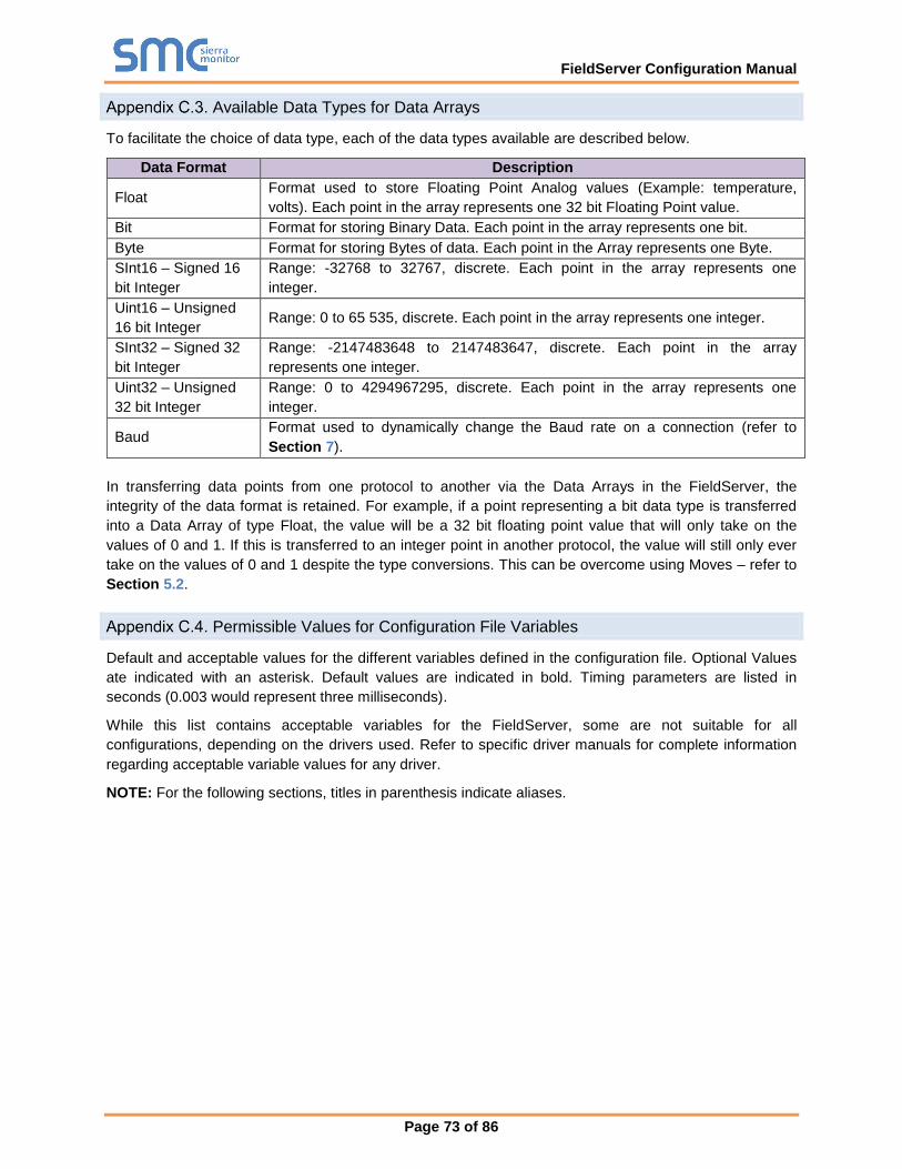
FieldServer Configuration Manual
Page 73 of 86
Available Data Types for Data Arrays
To facilitate the choice of data type, each of the data types available are described below.
Data Format Description
Float Format used to store Floating Point Analog values (Example: temperature,
volts). Each point in the array represents one 32 bit Floating Point value.
Bit Format for storing Binary Data. Each point in the array represents one bit.
Byte Format for storing Bytes of data. Each point in the Array represents one Byte.
SInt16 – Signed 16
bit Integer
Range: -32768 to 32767, discrete. Each point in the array represents one
integer.
Uint16 – Unsigned
16 bit Integer Range: 0 to 65 535, discrete. Each point in the array represents one integer.
SInt32 – Signed 32
bit Integer
Range: -2147483648 to 2147483647, discrete. Each point in the array
represents one integer.
Uint32 – Unsigned
32 bit Integer
Range: 0 to 4294967295, discrete. Each point in the array represents one
integer.
Baud Format used to dynamically change the Baud rate on a connection (refer to
Section 7).
In transferring data points from one protocol to another via the Data Arrays in the FieldServer, the
integrity of the data format is retained. For example, if a point representing a bit data type is transferred
into a Data Array of type Float, the value will be a 32 bit floating point value that will only take on the
values of 0 and 1. If this is transferred to an integer point in another protocol, the value will still only ever
take on the values of 0 and 1 despite the type conversions. This can be overcome using Moves – refer to
Section 5.2.
Permissible Values for Configuration File Variables
Default and acceptable values for the different variables defined in the configuration file. Optional Values
ate indicated with an asterisk. Default values are indicated in bold. Timing parameters are listed in
seconds (0.003 would represent three milliseconds).
While this list contains acceptable variables for the FieldServer, some are not suitable for all
configurations, depending on the drivers used. Refer to specific driver manuals for complete information
regarding acceptable variable values for any driver.
NOTE: For the following sections, titles in parenthesis indicate aliases.

FieldServer Configuration Manual
Page 74 of 86
Appendix C.4.1. Common Information
Section Title
FieldServer
Column Title Function Legal Values
Title Allows user to specify the title of the FieldServer. Title Text
Cache_Age;
(Cache_Age_Timeout)*
When poll block caching is used, data previously polled and stored in an
internal data buffer is returned to the Server, providing the data is not too
old. This parameter specifies the length of time cached data is valid.
Time in
seconds, 300s
Cache_Size* Specify size of Cache. 0-1000; 80
Cache_Time_To_Live*
Used for Port Expansion. A cache is created for data from a Node for
which no Map Descriptor is configured. If this data is not accessed for
longer that the time specified by this parameter, the cache will be
cleared.
Time in
seconds, 300s
Tier*
FieldServers have the ability to run as “multiple” FieldServers on one
platform. To differentiate between the different running applications,
each of the applications is referred to as a Tier with a specific name.
2
FieldServer_Name* A name by which a FieldServer is identified - need not be unique. Default value
blank
Cache_Age_Limit* Maximum age of data in a cache Map Descriptor for immediate response
to poll. 5 minutes
System_Node_ID
(System_ station_address
or System_station) *
Use is driver dependent. Generally used to identify the FieldServer as a
Node when it is configured as a Server. 1
Network_number* Displayed where a protocol requires the FieldServer to be assigned a
network number (such as BACnet). 5
Hot_Standby_Mode*
Where specified, this parameter defines the behavior of the standby
FieldServer in Hot Standby mode. In Mode 1 the FieldServer is
completely passive; in Mode 2 the standby FieldServer polls the
connected devices through alternate communication paths.
Default value
blank
Port_Expander_Mode* Indicates whether the port expander mode function is enabled or not. Default value
blank
Cache_Map_Descriptor_Sc
an_Interval*
If the value 65535 is displayed, then this is an error and it indicates that
there is no setting. 2 seconds
Hot_Standby_Designation*
Primary or Secondary. On boot the primary tries to become the active
and the secondary tries to become the standby FieldServer. This
behavior may be different if the so called secondary FieldServer gets re-
booted first.
Primary
Hot_Standby_Pair_Name*
A name by which a pair of FieldServers configured as a Hot Standby pair
is known. When one of a pair boots, it broadcasts a message with its
pair name in order to try and locate the other FieldServer that forms the
hot standby pair.
Default value
blank
Pex_Mode* Specify if Pex_Mode should be enabled or disabled. Refer to Section 8.
Default value
blank or
Enabled,
Disabled
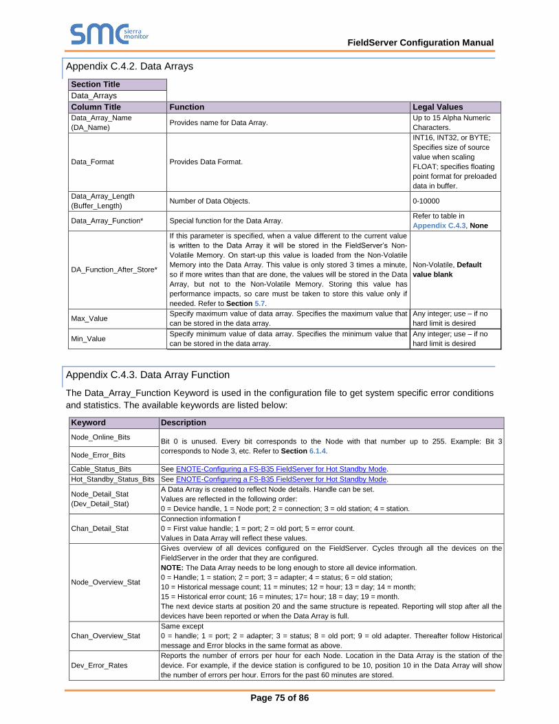
FieldServer Configuration Manual
Page 75 of 86
Appendix C.4.2. Data Arrays
Section Title
Data_Arrays
Column Title Function Legal Values
Data_Array_Name
(DA_Name) Provides name for Data Array.
Up to 15 Alpha Numeric
Characters.
Data_Format Provides Data Format.
INT16, INT32, or BYTE;
Specifies size of source
value when scaling
FLOAT; specifies floating
point format for preloaded
data in buffer.
Data_Array_Length
(Buffer_Length) Number of Data Objects. 0-10000
Data_Array_Function* Special function for the Data Array. Refer to table in
Appendix C.4.3, None
DA_Function_After_Store*
If this parameter is specified, when a value different to the current value
is written to the Data Array it will be stored in the FieldServer’s Non-
Volatile Memory. On start-up this value is loaded from the Non-Volatile
Memory into the Data Array. This value is only stored 3 times a minute,
so if more writes than that are done, the values will be stored in the Data
Array, but not to the Non-Volatile Memory. Storing this value has
performance impacts, so care must be taken to store this value only if
needed. Refer to Section 5.7.
Non-Volatile, Default
value blank
Max_Value Specify maximum value of data array. Specifies the maximum value that
can be stored in the data array.
Any integer; use – if no
hard limit is desired
Min_Value Specify minimum value of data array. Specifies the minimum value that
can be stored in the data array.
Any integer; use – if no
hard limit is desired
Appendix C.4.3. Data Array Function
The Data_Array_Function Keyword is used in the configuration file to get system specific error conditions
and statistics. The available keywords are listed below:
Keyword Description
Node_Online_Bits Bit 0 is unused. Every bit corresponds to the Node with that number up to 255. Example: Bit 3
corresponds to Node 3, etc. Refer to Section 6.1.4. Node_Error_Bits
Cable_Status_Bits See ENOTE-Configuring a FS-B35 FieldServer for Hot Standby Mode.
Hot_Standby_Status_Bits See ENOTE-Configuring a FS-B35 FieldServer for Hot Standby Mode.
Node_Detail_Stat
(Dev_Detail_Stat)
A Data Array is created to reflect Node details. Handle can be set.
Values are reflected in the following order:
0 = Device handle, 1 = Node port; 2 = connection; 3 = old station; 4 = station.
Chan_Detail_Stat
Connection information f
0 = First value handle; 1 = port; 2 = old port; 5 = error count.
Values in Data Array will reflect these values.
Node_Overview_Stat
Gives overview of all devices configured on the FieldServer. Cycles through all the devices on the
FieldServer in the order that they are configured.
NOTE: The Data Array needs to be long enough to store all device information.
0 = Handle; 1 = station; 2 = port; 3 = adapter; 4 = status; 6 = old station;
10 = Historical message count; 11 = minutes; 12 = hour; 13 = day; 14 = month;
15 = Historical error count; 16 = minutes; 17= hour; 18 = day; 19 = month.
The next device starts at position 20 and the same structure is repeated. Reporting will stop after all the
devices have been reported or when the Data Array is full.
Chan_Overview_Stat
Same except
0 = handle; 1 = port; 2 = adapter; 3 = status; 8 = old port; 9 = old adapter. Thereafter follow Historical
message and Error blocks in the same format as above.
Dev_Error_Rates
Reports the number of errors per hour for each Node. Location in the Data Array is the station of the
device. For example, if the device station is configured to be 10, position 10 in the Data Array will show
the number of errors per hour. Errors for the past 60 minutes are stored.
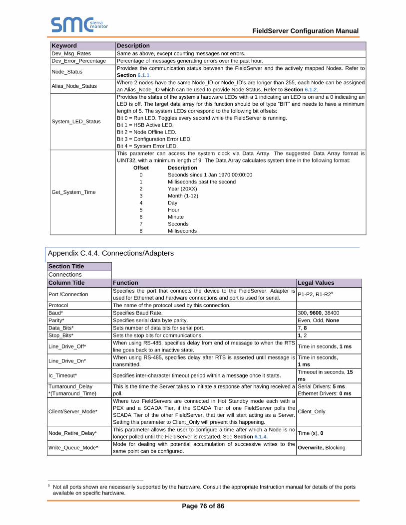
FieldServer Configuration Manual
Page 76 of 86
Keyword Description
Dev_Msg_Rates Same as above, except counting messages not errors.
Dev_Error_Percentage Percentage of messages generating errors over the past hour.
Node_Status Provides the communication status between the FieldServer and the actively mapped Nodes. Refer to
Section 6.1.1.
Alias_Node_Status Where 2 nodes have the same Node_ID or Node_ID’s are longer than 255, each Node can be assigned
an Alias_Node_ID which can be used to provide Node Status. Refer to Section 6.1.2.
System_LED_Status
Provides the states of the system’s hardware LEDs with a 1 indicating an LED is on and a 0 indicating an
LED is off. The target data array for this function should be of type “BIT” and needs to have a minimum
length of 5. The system LEDs correspond to the following bit offsets:
Bit 0 = Run LED. Toggles every second while the FieldServer is running.
Bit 1 = HSB Active LED.
Bit 2 = Node Offline LED.
Bit 3 = Configuration Error LED.
Bit 4 = System Error LED.
Get_System_Time
This parameter can access the system clock via Data Array. The suggested Data Array format is
UINT32, with a minimum length of 9. The Data Array calculates system time in the following format:
Offset
0
1
2
3
4
5
6
7
8
Description
Seconds since 1 Jan 1970 00:00:00
Milliseconds past the second
Year (20XX)
Month (1-12)
Day
Hour
Minute
Seconds
Milliseconds
Appendix C.4.4. Connections/Adapters
Section Title
Connections
Column Title Function Legal Values
Port /Connection Specifies the port that connects the device to the FieldServer. Adapter is
used for Ethernet and hardware connections and port is used for serial. P1-P2, R1-R29
Protocol The name of the protocol used by this connection.
Baud* Specifies Baud Rate. 300, 9600, 38400
Parity* Specifies serial data byte parity. Even, Odd, None
Data_Bits* Sets number of data bits for serial port. 7, 8
Stop_Bits* Sets the stop bits for communications. 1, 2
Line_Drive_Off* When using RS-485, specifies delay from end of message to when the RTS
line goes back to an inactive state. Time in seconds, 1 ms
Line_Drive_On* When using RS-485, specifies delay after RTS is asserted until message is
transmitted.
Time in seconds,
1 ms
Ic_Timeout* Specifies inter-character timeout period within a message once it starts. Timeout in seconds, 15
ms
Turnaround_Delay
*(Turnaround_Time)
This is the time the Server takes to initiate a response after having received a
poll.
Serial Drivers: 5 ms
Ethernet Drivers: 0 ms
Client/Server_Mode*
Where two FieldServers are connected in Hot Standby mode each with a
PEX and a SCADA Tier, if the SCADA Tier of one FieldServer polls the
SCADA Tier of the other FieldServer, that tier will start acting as a Server.
Setting this parameter to Client_Only will prevent this happening.
Client_Only
Node_Retire_Delay* This parameter allows the user to configure a time after which a Node is no
longer polled until the FieldServer is restarted. See Section 6.1.4. Time (s), 0
Write_Queue_Mode* Mode for dealing with potential accumulation of successive writes to the
same point can be configured. Overwrite, Blocking
9 Not all ports shown are necessarily supported by the hardware. Consult the appropriate Instruction manual for details of the ports
available on specific hardware.

FieldServer Configuration Manual
Page 77 of 86
Write_Queue_Size*
The length of the queue can be configured if blocking mode is set. Blocking
will occur when there is no more space on the Write_Queue.
If size=0 every successive write is blocked. A message will be displayed
when blocking occurs, except if the Queue_Size=0.
Non-negative integer, 0
Bias_Mode*
Only relevant to ProtoNode. If this parameter is set to Yes or Enabled, it
loads the RS-485 line by placing additional resistance on it This has the
benefit of making the signals cleaner in a noisy environment but may reduce
the maximum number of devices possible in a multidrop configuration.
Enabled, Yes, Disabled,
No
Poll_Delay*
The minimum amount of time that must pass between one Client Map
Descriptor completing its task and the next Client Map Descriptor being
serviced. Refer to Driver Manuals.
.05 seconds
Low_Pri_Poll_Delay* The poll delay used for lower priority Map Descriptors. Protocol dependent
Server_Hold_Timeout*
When an upstream device polls the FieldServer, and the data is unavailable
or too old, the driver generates a poll to the downstream device for fresh
data, (port expansion). The Server_Hold_Timeout defines the time available
for this transaction to complete before an error is returned.
2 seconds
IP_Address* An IP Address for the connection if applicable.
Remote_IP_Address* A remote IP Address for the connection if applicable.
Timeout* The timeout defined for the connection. 2 seconds
Recovery_Interval* The time after a node goes off-line before the driver tries to poll the device
again. 30 seconds
Probation_Delay* The length of time communication needs to be re-established for before an
offline Client node is marked on-line again. 1 minute
Multidrop_Mode* Indicates whether Multidrop mode is enabled or not. Multidrop mode allows a
server to ignore requests to nodes that are not configured.
Enabled for RS-485,
disabled for RS-232
IP_port*
Determined by specific driver or protocol used. See Driver Manual.
Remote_IP_Port*
Max_Master*
Max_Info_Frames*
Connection_Type*
Application*
TLS_Port
Refer to Section 10.
Validate_Client_Cert
Cert_Authority_File
Check_Remote_Host
Server_Cert_File
Section Title
Adapter
Column Title Function Legal Values
Adapter Adaptor name DH+, Modbus+, PROFIBUS, etc
MAC_Address (Net_number) Specify Network MAC address
Appendix C.4.5. Nodes
Section Title
Nodes
Column Title Function Legal Values
Node_Name (Device_Name) The node name specified in the CSV file. Up to 32 Alpha Numeric Characters
Node_ID*
The station number or address of the node. The actual
meaning is dependent on the driver and protocol – refer to the
Driver Manual.
1-255
Protocol The protocol being used to update the data for that node. Refer
to the Driver Manual. Modbus/TCP etc.
IP_Address* IP Address of the Server Device. Valid IP Address, -
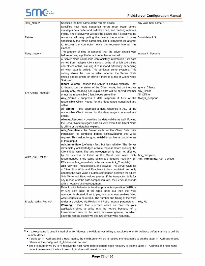
FieldServer Configuration Manual
Page 78 of 86
Host_Name* Specifies the host name of the remote device. Any valid host name10, -
Retries*
Specifies how many sequential errors must occur before
marking a data buffer and poll block bad, and marking a device
offline. The FieldServer will poll the device and if it receives no
response will retry polling the device the number of times
specified by the retries parameter. The FieldServer will attempt
to recover the connection once the recovery interval has
elapsed.
Count default 3
Retry_Interval* The amount of time in seconds that the driver should wait
before retrying a poll after a timeout has occurred. Interval in Seconds
Srv_Offline_Method*
A Server Node could send contradictory information if its data
comes from multiple Client Nodes, some of which are offline
and others online, causing it to respond differently depending
on what data is polled. This confuses some systems. This
setting allows the user to select whether the Server Node
should appear online or offline if there is a mix of Client Node
Statuses.
Ignore_Clients - causes the Server to behave explicitly – not
to depend on the status of the Client Node, but on the data
validity only. Meaning non-expired data will be served whether
or not the responsible Client Nodes are online.
Any_Offline - suppress a data response if ANY of the
responsible Client Nodes for the data range concerned are
offline
All_Offline - only suppress a data response if ALL of the
responsible Client Nodes for the data range concerned are
offline.
Always_Respond - overrides the data validity as well. Forcing
the Server Node to regard data as valid even if the Client Node
is offline or the data has expired.
Ignore_Clients
Any_Offline
All_Offline
Always_Respond
Write_Ack_Option*
Ack_Complete - the Server waits for the Client Side write
transaction to complete before acknowledging the Write
request. This makes for good reliability but has a cost in terms
of throughput.
Ack_Immediate (default) - fast, but less reliable. The Server
immediately acknowledges a Write request before queuing the
Client Side Write. The acknowledgement is thus not affected
by the success or failure of the Client Side Write. Only
recommended if the same points are updated regularly. (In
PEX mode Ack_Immediate is the same as Ack_Complete).
Ack_Verified - most reliable, and slowest. The Server waits for
a Client Side Write and Readback to be completed, and only
updates the data value if a data comparison between the Client
Side Write and Read values passes. If the transaction fails for
any reason or if the data comparison fails, the Server responds
with a negative acknowledgement.
Ack_Complete,
Ack_Immediate, Ack_Verified
Enable_Write_Retries*
Default write behavior is to attempt a write operation (WRB or
WRBX) only once. If the write times out then the write
operation is aborted. If set to yes, this parameter enables failed
write requests to be retried. The number and timing of the write
retries are decided via Retries and Retry_Interval parameters.
Warning: Ensure that repeated writes are safe for your
application since a Write may be retried because of a
transmission error in the Write acknowledgement, in which
case the remote device will see two similar write requests.
Yes, No
10 ▪ If a Host name is used instead of an IP Address, the FieldServer will try to resolve it to an IP_Address before starting to poll the
remote device.
▪ If using an IP_Address and a Host_Name, the FieldServer will try to resolve the host name to get the latest IP_Address to use,
otherwise the configured IP_Address will be used.
▪ The FieldServer will try to re-resolve the host name before starting node recovery to get the latest IP_Address. If a host name
cannot be resolved, the last known IP_Address will remain in use.

FieldServer Configuration Manual
Page 79 of 86
Node_Offline_Action*
If this parameter is defined, when a Client Node goes offline,
all Data Array values of Map Descriptors defined on this Node
will be set to zero.
Clear_Data_Array, No_Action, -
Remote_IP_Address* The remote IP Address used by this node. Required for protocols that use it
Node_Type* Specified in the configuration file as the PLC_Type. - Consult
the driver manual for additional information. Required for protocols that use it
Port* Port number for a serial connection.
Readback_Option*
This Client Side parameter enables the user to configure the
timing of a read after a write. The Readback operation will
apply to all drivers that support Active Reads and Write-
Through operations.
Readback_Asynchronously - When a write occurs, the read
will occur when scheduled.
Readback_On_Write - When a write occurs, set the timer to 0,
so Responsible Map Descriptor gets queued in the next cycle.
Readback_Immediately_On_Write - Prioritize both write and
read to happen in a higher priority queue than normal reads.
The Readback operation will apply to all drivers that support
Active Reads and Write-Through operation.
Readback_On_Write,
Readback_Asynchronously,
Readback_Immediately_On_Write
MAC_Address* Required for protocols that use it, not needed for other.
Specified by remote Mac Address of the device. Required for protocols that use it
Node_Offline_response* The type of response the Server side of the driver sends when
it finds the Server node to be offline.
No_Response, Old_Data,
Zero_Data, FFFF_Data (not valid for
all protocols)
Timeout* The timeout specified for the node. 2 seconds
Recovery_Interval* The time in seconds after a node goes off-line before the driver
tries to poll the device again. 30 seconds
Probation_Delay* The length of time communication needs to be re-established
for before an offline Client node is marked on-line again. 1 minute
Server_Name*
An alternate to specifying the IP Address. Used when the user
wants two nodes to talk to each other. When specified, the
FieldServer sends out a broadcast with the server name and
uses the reply to fill in the IP Address for the node. Until the
reply has been received all polling for the node is disabled. The
server name given should correspond to the pair_name
specified in the remote FieldServer’s bridge settings.
Only applies to the SMT protocol
Alias_Node_ID*
Used to distinguish between different nodes connected to the
FieldServer when a PLC does not support the allocation of
different None_ID’s. Each node is given a different alias.
Upstream devices poll the Alias_Node_ID and the FieldServer
routes the poll to the correct PLC, polled using the Node_ID.
Any integer, -
Ports_on_PLC* For hot standby operation. This field is used to control which
port on a PLC to poll.
See ENOTE-Configuring a FS-B35
FieldServer for Hot Standby Mode
Remote_Node_TLS_Port
Refer to Section 10.
Validate_Server_Cert
Cert_Authority_File
Check_Remote_Host
Client_Cert_File
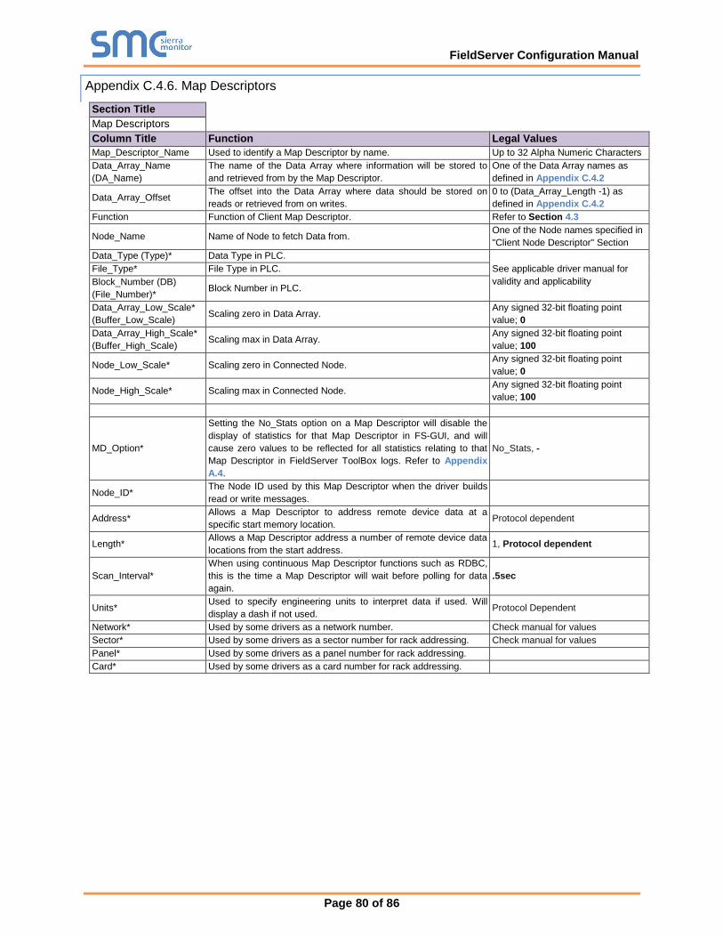
FieldServer Configuration Manual
Page 80 of 86
Appendix C.4.6. Map Descriptors
Section Title
Map Descriptors
Column Title Function Legal Values
Map_Descriptor_Name Used to identify a Map Descriptor by name. Up to 32 Alpha Numeric Characters
Data_Array_Name
(DA_Name)
The name of the Data Array where information will be stored to
and retrieved from by the Map Descriptor.
One of the Data Array names as
defined in Appendix C.4.2
Data_Array_Offset The offset into the Data Array where data should be stored on
reads or retrieved from on writes.
0 to (Data_Array_Length -1) as
defined in Appendix C.4.2
Function Function of Client Map Descriptor. Refer to Section 4.3
Node_Name Name of Node to fetch Data from. One of the Node names specified in
"Client Node Descriptor" Section
Data_Type (Type)* Data Type in PLC.
See applicable driver manual for
validity and applicability
File_Type* File Type in PLC.
Block_Number (DB)
(File_Number)* Block Number in PLC.
Data_Array_Low_Scale*
(Buffer_Low_Scale) Scaling zero in Data Array.
Any signed 32-bit floating point
value; 0
Data_Array_High_Scale*
(Buffer_High_Scale) Scaling max in Data Array.
Any signed 32-bit floating point
value; 100
Node_Low_Scale* Scaling zero in Connected Node. Any signed 32-bit floating point
value; 0
Node_High_Scale* Scaling max in Connected Node. Any signed 32-bit floating point
value; 100
MD_Option*
Setting the No_Stats option on a Map Descriptor will disable the
display of statistics for that Map Descriptor in FS-GUI, and will
cause zero values to be reflected for all statistics relating to that
Map Descriptor in FieldServer ToolBox logs. Refer to Appendix
A.4.
No_Stats, -
Node_ID* The Node ID used by this Map Descriptor when the driver builds
read or write messages.
Address* Allows a Map Descriptor to address remote device data at a
specific start memory location. Protocol dependent
Length* Allows a Map Descriptor address a number of remote device data
locations from the start address. 1, Protocol dependent
Scan_Interval*
When using continuous Map Descriptor functions such as RDBC,
this is the time a Map Descriptor will wait before polling for data
again.
.5sec
Units* Used to specify engineering units to interpret data if used. Will
display a dash if not used. Protocol Dependent
Network* Used by some drivers as a network number. Check manual for values
Sector* Used by some drivers as a sector number for rack addressing. Check manual for values
Panel* Used by some drivers as a panel number for rack addressing.
Card* Used by some drivers as a card number for rack addressing.
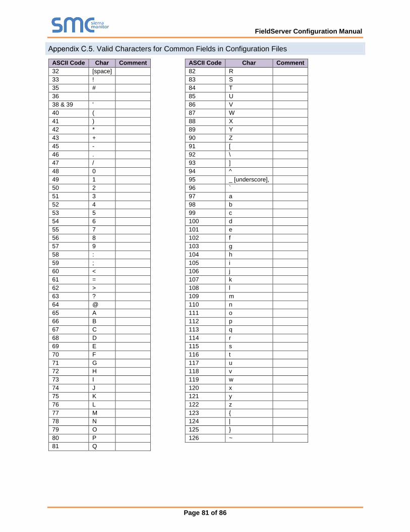
FieldServer Configuration Manual
Page 81 of 86
Valid Characters for Common Fields in Configuration Files
ASCII Code Char Comment ASCII Code Char Comment
32 [space] 82 R
33 ! 83 S
35 # 84 T
36 85 U
38 & 39 ‘ 86 V
40 ( 87 W
41 ) 88 X
42 * 89 Y
43 + 90 Z
45 - 91 [
46 . 92 \
47 / 93 ]
48 0 94 ^
49 1 95 _ [underscore],
50 2 96 `
51 3 97 a
52 4 98 b
53 5 99 c
54 6 100 d
55 7 101 e
56 8 102 f
57 9 103 g
58 : 104 h
59 ; 105 i
60 < 106 j
61 = 107 k
62 > 108 l
63 ? 109 m
64 @ 110 n
65 A 111 o
66 B 112 p
67 C 113 q
68 D 114 r
69 E 115 s
70 F 116 t
71 G 117 u
72 H 118 v
73 I 119 w
74 J 120 x
75 K 121 y
76 L 122 z
77 M 123 {
78 N 124 |
79 O 125 }
80 P 126 ~
81 Q
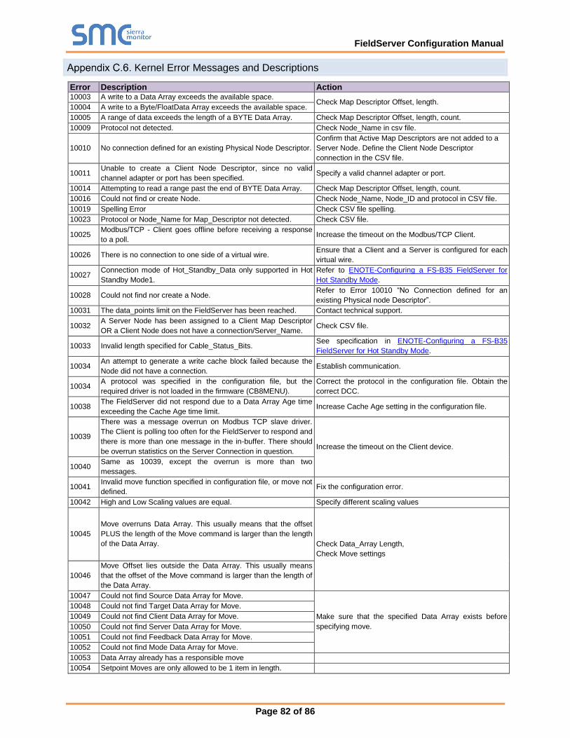
FieldServer Configuration Manual
Page 82 of 86
Kernel Error Messages and Descriptions
Error Description Action 10003 A write to a Data Array exceeds the available space.
Check Map Descriptor Offset, length. 10004 A write to a Byte/FloatData Array exceeds the available space.
10005 A range of data exceeds the length of a BYTE Data Array. Check Map Descriptor Offset, length, count.
10009 Protocol not detected. Check Node_Name in csv file.
10010 No connection defined for an existing Physical Node Descriptor.
Confirm that Active Map Descriptors are not added to a
Server Node. Define the Client Node Descriptor
connection in the CSV file.
10011 Unable to create a Client Node Descriptor, since no valid
channel adapter or port has been specified. Specify a valid channel adapter or port.
10014 Attempting to read a range past the end of BYTE Data Array. Check Map Descriptor Offset, length, count.
10016 Could not find or create Node. Check Node_Name, Node_ID and protocol in CSV file.
10019 Spelling Error Check CSV file spelling.
10023 Protocol or Node_Name for Map_Descriptor not detected. Check CSV file.
10025 Modbus/TCP - Client goes offline before receiving a response
to a poll. Increase the timeout on the Modbus/TCP Client.
10026 There is no connection to one side of a virtual wire. Ensure that a Client and a Server is configured for each
virtual wire.
10027 Connection mode of Hot_Standby_Data only supported in Hot
Standby Mode1.
Refer to ENOTE-Configuring a FS-B35 FieldServer for
Hot Standby Mode.
10028 Could not find nor create a Node. Refer to Error 10010 “No Connection defined for an
existing Physical node Descriptor”.
10031 The data_points limit on the FieldServer has been reached. Contact technical support.
10032 A Server Node has been assigned to a Client Map Descriptor
OR a Client Node does not have a connection/Server_Name. Check CSV file.
10033 Invalid length specified for Cable_Status_Bits. See specification in ENOTE-Configuring a FS-B35
FieldServer for Hot Standby Mode.
10034 An attempt to generate a write cache block failed because the
Node did not have a connection. Establish communication.
10034 A protocol was specified in the configuration file, but the
required driver is not loaded in the firmware (CB8MENU).
Correct the protocol in the configuration file. Obtain the
correct DCC.
10038 The FieldServer did not respond due to a Data Array Age time
exceeding the Cache Age time limit. Increase Cache Age setting in the configuration file.
10039
There was a message overrun on Modbus TCP slave driver.
The Client is polling too often for the FieldServer to respond and
there is more than one message in the in-buffer. There should
be overrun statistics on the Server Connection in question. Increase the timeout on the Client device.
10040 Same as 10039, except the overrun is more than two
messages.
10041 Invalid move function specified in configuration file, or move not
defined. Fix the configuration error.
10042 High and Low Scaling values are equal. Specify different scaling values
10045
Move overruns Data Array. This usually means that the offset
PLUS the length of the Move command is larger than the length
of the Data Array. Check Data_Array Length,
Check Move settings
10046
Move Offset lies outside the Data Array. This usually means
that the offset of the Move command is larger than the length of
the Data Array.
10047 Could not find Source Data Array for Move.
Make sure that the specified Data Array exists before
specifying move.
10048 Could not find Target Data Array for Move.
10049 Could not find Client Data Array for Move.
10050 Could not find Server Data Array for Move.
10051 Could not find Feedback Data Array for Move.
10052 Could not find Mode Data Array for Move.
10053 Data Array already has a responsible move
10054 Setpoint Moves are only allowed to be 1 item in length.
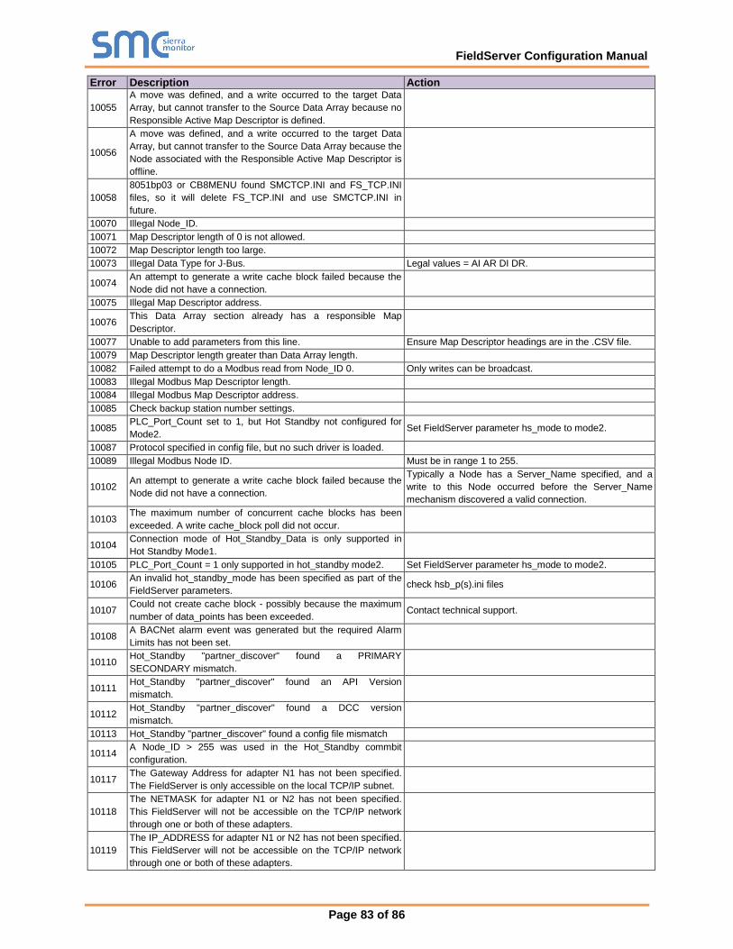
FieldServer Configuration Manual
Page 83 of 86
Error Description Action
10055
A move was defined, and a write occurred to the target Data
Array, but cannot transfer to the Source Data Array because no
Responsible Active Map Descriptor is defined.
10056
A move was defined, and a write occurred to the target Data
Array, but cannot transfer to the Source Data Array because the
Node associated with the Responsible Active Map Descriptor is
offline.
10058
8051bp03 or CB8MENU found SMCTCP.INI and FS_TCP.INI
files, so it will delete FS_TCP.INI and use SMCTCP.INI in
future.
10070 Illegal Node_ID.
10071 Map Descriptor length of 0 is not allowed.
10072 Map Descriptor length too large.
10073 Illegal Data Type for J-Bus. Legal values = AI AR DI DR.
10074 An attempt to generate a write cache block failed because the
Node did not have a connection.
10075 Illegal Map Descriptor address.
10076 This Data Array section already has a responsible Map
Descriptor.
10077 Unable to add parameters from this line. Ensure Map Descriptor headings are in the .CSV file.
10079 Map Descriptor length greater than Data Array length.
10082 Failed attempt to do a Modbus read from Node_ID 0. Only writes can be broadcast.
10083 Illegal Modbus Map Descriptor length.
10084 Illegal Modbus Map Descriptor address.
10085 Check backup station number settings.
10085 PLC_Port_Count set to 1, but Hot Standby not configured for
Mode2. Set FieldServer parameter hs_mode to mode2.
10087 Protocol specified in config file, but no such driver is loaded.
10089 Illegal Modbus Node ID. Must be in range 1 to 255.
10102 An attempt to generate a write cache block failed because the
Node did not have a connection.
Typically a Node has a Server_Name specified, and a
write to this Node occurred before the Server_Name
mechanism discovered a valid connection.
10103 The maximum number of concurrent cache blocks has been
exceeded. A write cache_block poll did not occur.
10104 Connection mode of Hot_Standby_Data is only supported in
Hot Standby Mode1.
10105 PLC_Port_Count = 1 only supported in hot_standby mode2. Set FieldServer parameter hs_mode to mode2.
10106 An invalid hot_standby_mode has been specified as part of the
FieldServer parameters. check hsb_p(s).ini files
10107 Could not create cache block - possibly because the maximum
number of data_points has been exceeded. Contact technical support.
10108 A BACNet alarm event was generated but the required Alarm
Limits has not been set.
10110 Hot_Standby "partner_discover" found a PRIMARY
SECONDARY mismatch.
10111 Hot_Standby "partner_discover" found an API Version
mismatch.
10112 Hot_Standby "partner_discover" found a DCC version
mismatch.
10113 Hot_Standby "partner_discover" found a config file mismatch
10114 A Node_ID > 255 was used in the Hot_Standby commbit
configuration.
10117 The Gateway Address for adapter N1 has not been specified. The FieldServer is only accessible on the local TCP/IP subnet.
10118
The NETMASK for adapter N1 or N2 has not been specified.
This FieldServer will not be accessible on the TCP/IP network
through one or both of these adapters.
10119
The IP_ADDRESS for adapter N1 or N2 has not been specified.
This FieldServer will not be accessible on the TCP/IP network
through one or both of these adapters.
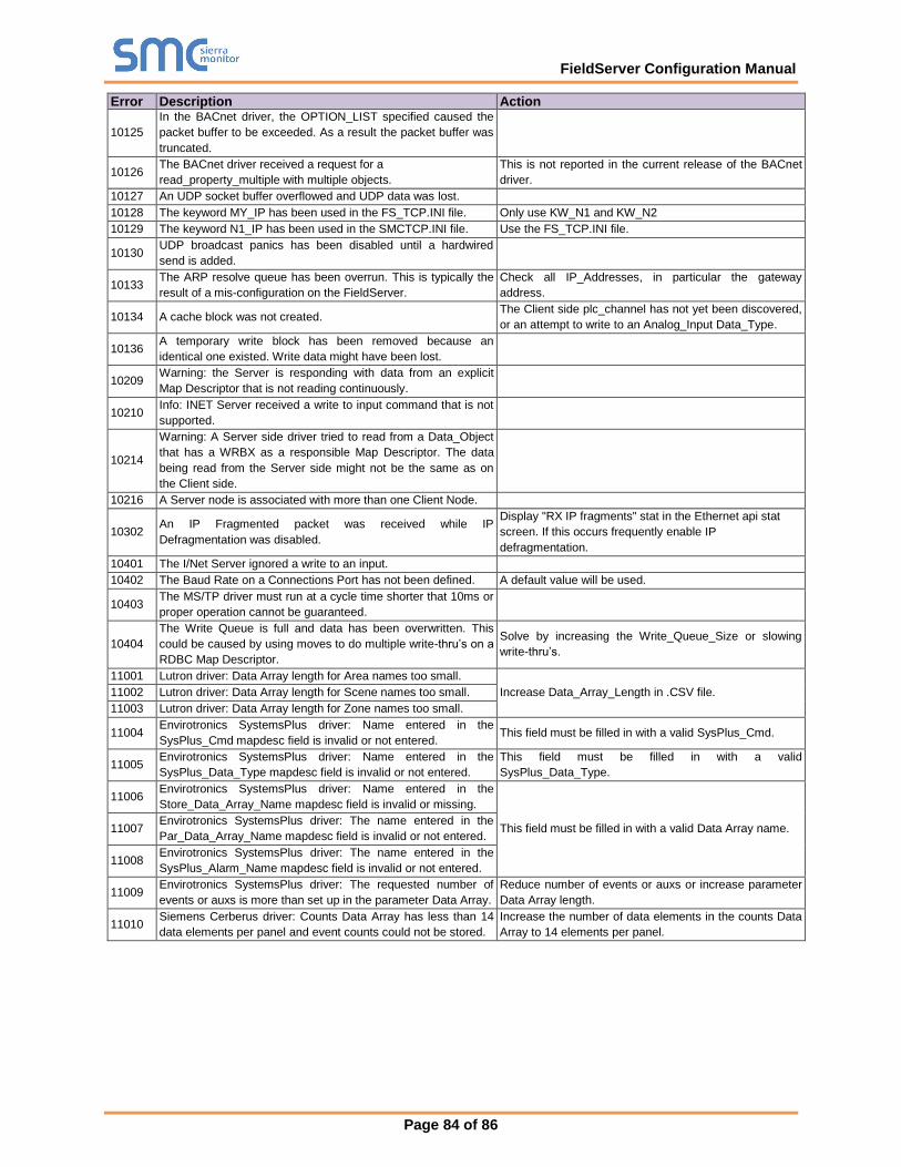
FieldServer Configuration Manual
Page 84 of 86
Error Description Action
10125
In the BACnet driver, the OPTION_LIST specified caused the
packet buffer to be exceeded. As a result the packet buffer was
truncated.
10126 The BACnet driver received a request for a
read_property_multiple with multiple objects.
This is not reported in the current release of the BACnet
driver.
10127 An UDP socket buffer overflowed and UDP data was lost.
10128 The keyword MY_IP has been used in the FS_TCP.INI file. Only use KW_N1 and KW_N2
10129 The keyword N1_IP has been used in the SMCTCP.INI file. Use the FS_TCP.INI file.
10130 UDP broadcast panics has been disabled until a hardwired
send is added.
10133 The ARP resolve queue has been overrun. This is typically the
result of a mis-configuration on the FieldServer.
Check all IP_Addresses, in particular the gateway
address.
10134 A cache block was not created. The Client side plc_channel has not yet been discovered,
or an attempt to write to an Analog_Input Data_Type.
10136 A temporary write block has been removed because an
identical one existed. Write data might have been lost.
10209 Warning: the Server is responding with data from an explicit
Map Descriptor that is not reading continuously.
10210 Info: INET Server received a write to input command that is not
supported.
10214
Warning: A Server side driver tried to read from a Data_Object
that has a WRBX as a responsible Map Descriptor. The data
being read from the Server side might not be the same as on
the Client side.
10216 A Server node is associated with more than one Client Node.
10302 An IP Fragmented packet was received while IP
Defragmentation was disabled.
Display "RX IP fragments" stat in the Ethernet api stat
screen. If this occurs frequently enable IP
defragmentation.
10401 The I/Net Server ignored a write to an input.
10402 The Baud Rate on a Connections Port has not been defined. A default value will be used.
10403 The MS/TP driver must run at a cycle time shorter that 10ms or
proper operation cannot be guaranteed.
10404
The Write Queue is full and data has been overwritten. This
could be caused by using moves to do multiple write-thru’s on a
RDBC Map Descriptor.
Solve by increasing the Write_Queue_Size or slowing
write-thru’s.
11001 Lutron driver: Data Array length for Area names too small.
Increase Data_Array_Length in .CSV file. 11002 Lutron driver: Data Array length for Scene names too small.
11003 Lutron driver: Data Array length for Zone names too small.
11004 Envirotronics SystemsPlus driver: Name entered in the
SysPlus_Cmd mapdesc field is invalid or not entered. This field must be filled in with a valid SysPlus_Cmd.
11005 Envirotronics SystemsPlus driver: Name entered in the
SysPlus_Data_Type mapdesc field is invalid or not entered.
This field must be filled in with a valid
SysPlus_Data_Type.
11006 Envirotronics SystemsPlus driver: Name entered in the
Store_Data_Array_Name mapdesc field is invalid or missing.
This field must be filled in with a valid Data Array name. 11007 Envirotronics SystemsPlus driver: The name entered in the
Par_Data_Array_Name mapdesc field is invalid or not entered.
11008 Envirotronics SystemsPlus driver: The name entered in the
SysPlus_Alarm_Name mapdesc field is invalid or not entered.
11009 Envirotronics SystemsPlus driver: The requested number of
events or auxs is more than set up in the parameter Data Array.
Reduce number of events or auxs or increase parameter
Data Array length.
11010 Siemens Cerberus driver: Counts Data Array has less than 14
data elements per panel and event counts could not be stored.
Increase the number of data elements in the counts Data
Array to 14 elements per panel.

FieldServer Configuration Manual
Page 85 of 86
Error Description Action
11011
Siemens Cerberus driver: Client driver could not find a suitable
Map Descriptor to store the incoming event. The error message
reported the event's panel, module and device numbers.
Use the event's panel, module and device numbers to
define a Map Descriptor with Node_Name = panel.
Example: For message: DRIVER-> CER : No mapdesc
for panel 2, module 15, device 4,
Create a mapdesc that will map to an address of15*256 +
4 = 3844, since there are always 256 devices per module
for Cerberus. The mapdesc field block_number
represents the Cerberus module number. A Cerberus
mapdesc maps to addresses from module*256 + 0 to
module*256 + (length-1). For example, the following
addresses are defined for a mapdesc of module 15 and
length 4: (15*256 +0); (15*256 +1) ; (15*256 +2); (15*256
+3). Our example event will cause this error message
since the greatest address is (15*256 +3) = 3843 and we
need an address of 3844. A mapdesc with module 15 and
length 5 will store the event ok, since (15*256 + (5-1)) =
(15*256 +4) = 3844.
11012
Envirotronics SystemsPlus driver: The SystemsPlus panel
replied with "Not Monitored" when the driver tried to edit read
scan alarm or tried to read alarm status. The driver message
screen records the specific alarm's name.
Refer to the SystemsPlus user manual to set up the alarm
for monitoring in the panel. This message can only be
solved in the panel and is not a driver problem.
11013 A BACnet Ethernet packet was received on a network adapter
that is not configured in the CSV file. Message will be ignored.
If BACnet comms fail, check the configuration and
network connection.
11014 An 802.3 (Hot Standby) packet was received on an incorrectly
configured network adapter. Packet will be discarded.
11015 GE SRTP - SD016 message indicates NAK error.
Networking Glossary of Terms
Term Description
10Base2
10Base2 is the implementation of the IEEE 802.3 Ethernet standard on thin coaxial cable. Thin Ethernet or
thinnet, as it is commonly called, runs at 10Mbps. Stations are daisy chained and the maximum segment
length is 200 meters.
10Base5
10Base5 is the implementation of the IEEE 802.3 Ethernet standard on thick coaxial cable. Thick or standard
Ethernet, as it is commonly called, runs at 10Mbps. It uses bus topology and the maximum segment length is
500 meters.
10BaseT
10BaseT is the implementation of the IEEE 802.3 Ethernet standard on unshielded twisted-pair wiring. It
uses star topology, with stations directly connected to a multi-port hub. It runs at 10Mbps, and has a
maximum segment length of 100 meters.
802.3
This IEEE standard governs the Carrier Sense Multiple Access/Collision Detection (CSMA/CD) networks,
which are more commonly called Ethernet. 802.3 networks operate at varying speeds and over different
cable types. See 10Base2, 10Base5 and 10BaseT.
Bandwidth
Bandwidth is the amount of data that can be transmitted over a channel, measured in bits per second. For
example, Ethernet has a 10Mbps bandwidth and FDDI has a 100 Mbps bandwidth. Actual throughput may
be different than the theoretical bandwidth.
FieldServer
A FieldServer connects two networks of the same access method, for example, Ethernet to Ethernet or
Token Ring to Token Ring. A FieldServer works at the OSI’s Media Access Layer, and is transparent to
upper-layer devices and protocols. FieldServers operate by filtering packets according to their destination
addresses. Most FieldServers automatically learn where these addresses are located, and thus are called
learning FieldServers.
Ethernet
Ethernet is a 10Mbps CSMA/CD network that runs over thick coax, thin coax, twisted-pair, and fiber-optic
cable. A thick coax Ethernet uses a bus topology. A thin coax Ethernet uses a daisy chain topology. A fiber
Ethernet is point-to-point. DIX or Blue Book Ethernet is the name of the Digital Equipment Corp., Intel and
Xerox specification; 8802/3 is the ISO’s specification.
Gateway
In OSI terminology, a gateway is a hardware and software device that connects two dissimilar systems such
as a LAN and a mainframe. It operates at the fourth through seventh layers of the OSI model. In Internet
terminology, a gateway is another name for a router.
GUI (FS-GUI) Graphical User Interface.
Hub
A concentrator is a hub repeater or concentrator that brings together the connections from multiple network
Nodes. Hubs have moved past their origins as wire concentrator centers, and often house FieldServers,
routers, and network-management devices.
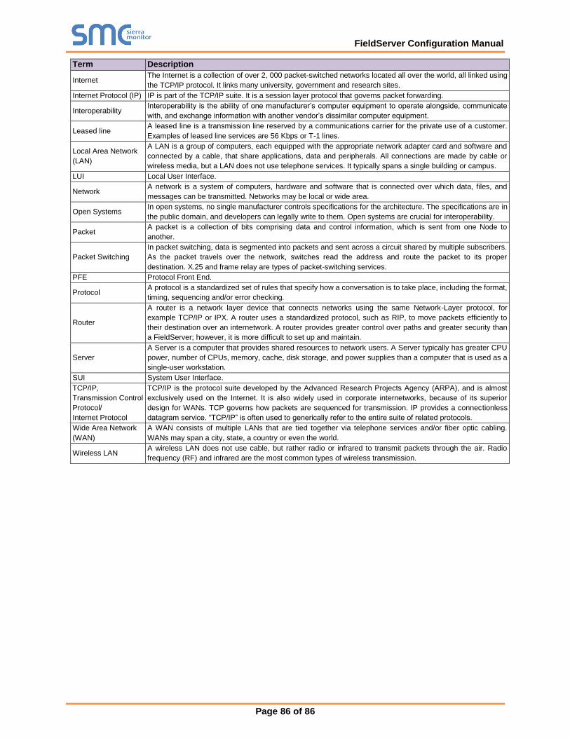
FieldServer Configuration Manual
Page 86 of 86
Term Description
Internet The Internet is a collection of over 2, 000 packet-switched networks located all over the world, all linked using
the TCP/IP protocol. It links many university, government and research sites.
Internet Protocol (IP) IP is part of the TCP/IP suite. It is a session layer protocol that governs packet forwarding.
Interoperability Interoperability is the ability of one manufacturer’s computer equipment to operate alongside, communicate
with, and exchange information with another vendor’s dissimilar computer equipment.
Leased line A leased line is a transmission line reserved by a communications carrier for the private use of a customer.
Examples of leased line services are 56 Kbps or T-1 lines.
Local Area Network
(LAN)
A LAN is a group of computers, each equipped with the appropriate network adapter card and software and
connected by a cable, that share applications, data and peripherals. All connections are made by cable or
wireless media, but a LAN does not use telephone services. It typically spans a single building or campus.
LUI Local User Interface.
Network A network is a system of computers, hardware and software that is connected over which data, files, and
messages can be transmitted. Networks may be local or wide area.
Open Systems In open systems, no single manufacturer controls specifications for the architecture. The specifications are in
the public domain, and developers can legally write to them. Open systems are crucial for interoperability.
Packet A packet is a collection of bits comprising data and control information, which is sent from one Node to
another.
Packet Switching
In packet switching, data is segmented into packets and sent across a circuit shared by multiple subscribers.
As the packet travels over the network, switches read the address and route the packet to its proper
destination. X.25 and frame relay are types of packet-switching services.
PFE Protocol Front End.
Protocol A protocol is a standardized set of rules that specify how a conversation is to take place, including the format,
timing, sequencing and/or error checking.
Router
A router is a network layer device that connects networks using the same Network-Layer protocol, for
example TCP/IP or IPX. A router uses a standardized protocol, such as RIP, to move packets efficiently to
their destination over an internetwork. A router provides greater control over paths and greater security than
a FieldServer; however, it is more difficult to set up and maintain.
Server
A Server is a computer that provides shared resources to network users. A Server typically has greater CPU
power, number of CPUs, memory, cache, disk storage, and power supplies than a computer that is used as a
single-user workstation.
SUI System User Interface.
TCP/IP,
Transmission Control
Protocol/
Internet Protocol
TCP/IP is the protocol suite developed by the Advanced Research Projects Agency (ARPA), and is almost
exclusively used on the Internet. It is also widely used in corporate internetworks, because of its superior
design for WANs. TCP governs how packets are sequenced for transmission. IP provides a connectionless
datagram service. “TCP/IP” is often used to generically refer to the entire suite of related protocols.
Wide Area Network
(WAN)
A WAN consists of multiple LANs that are tied together via telephone services and/or fiber optic cabling.
WANs may span a city, state, a country or even the world.
Wireless LAN A wireless LAN does not use cable, but rather radio or infrared to transmit packets through the air. Radio
frequency (RF) and infrared are the most common types of wireless transmission.