Embed Size (px)
Citation preview

the comprehensive selection for your installationfieldbus technology
2
Ex ic (nL)or Ex d, nA
Discrete Devices
Ex i
Ex d/m
Fieldbus Devices
Ex i/FISCO
Fieldbus Devices
Fieldbus Devices
Zone 2 Ex n FDC
Fieldbus
Power
Supply
Diagnostics
PLC/DCS
(host)
Terminator
Zone 1 Ex i FDC
Zone 2 Ex i FDC
Zone 1 Ex e FDC
Digital I/O Coupler
Asset ManagementLevel
Contro lLevel
F ie ld LevelZone 2
F ie ld LevelZone 1
12x Ex ic (nL)
8x Ex ia/FISCO
Fiel
dbus
FF
H1 h
igh
pow
er tr
unk
(Ex
e/N.
I.)Ba
ckbo
ne
Fieldbus FF H1
8x Ex ia/FISCO
4x Ex i output
8x Ex i input
8x Ex e
(12x Ex d, nA)
Modern and effective High Power Trunk installation
Proactive physical layer diagnostics
Trend monitoring
Reactive physical layer diagnostics
Optimized for Zone 2 / Zone 1
Power management with softstart
softstart
Online physical layer diagnostics
EDDLDTM
Reactive physical layer diagnostics
Proactive physical layer diagnostics
Online physical layer diagnostics
Trend monitoring
Power management with softstart
Optimized for Zone 2 / Zone 1

3
Fieldbus solutions
1
2
3
4
5
6
7
8
Three generations of field devices are in use in the process industries and hazardous areas today. There are the conventional sensors and actuators with analogue 4...20 mA signals and the HART field devices. Besides the point to point solutions with isolators, this does of course relate to explosion protected remote I/O systems where conventional and HART devices can be interfaced efficiently with automation systems using digital communication technologies like PROFIBUS DP or Fast Industrial Ethernet.
With FOUNDATION™ Fieldbus H1 and Profibus PA the third generation of field devices was introduced some years ago. The predominant types of protection for explosion protected sensors and actuators continue to be intrinsically safe “Ex i” and flameproof “Ex d” in Zone 1 and Division 1. The FISCO specification was developed for an intrinsical-ly safe fieldbus to increase the number of fieldbus devices per seg-ment. However, the number of connectable fieldbus devices is still small when using a pure FISCO fieldbus installation.
Far more power can be provided for much more fieldbus devices with the so-called “High Power Trunk” concept that utilizes a non-intrinsically safe fieldbus trunk that is connected to FISCO fieldbus devices via iso-lating device couplers. Today this is the best way of implementing an efficient and economical installation to power an adequately large number of fieldbus devices.
R.STAHL has made it business to provide efficient and economical solutions with suitable device couplers, fieldbus power supplies and advanced physical layer diagnostics tools for fieldbus installations. Customized solutions with enclosures in different materials and sizes, extensive accessories plus the long-time engineering experience for hazardous area applications round up the fieldbus product range of ISbus.
1 ISbus Fieldbus Power Supply2 ISbus Fieldbus Zone 1 Field Device Coupler3 ISbus Fieldbus Zone 2 Field Device Coupler4 ISbus Fieldbus Zone 1 Digital I/O Coupler
5 ISbus Fieldbus Diagnosis DTM6 Diagnosis Communicaton Module DCM7 Field Device Coupler, Zone 2 field enclosure8 Customized solution integrating
remote I/O and fieldbus FF H1

4
The ISbus Fielbus Power Supplies series 9412 serve for energy supply and signal conditio-ning of simple and redundant FOUNDATION™ Fieldbus H1 segments.
All 9412 Fieldbus Power Supplies feature inte-grated advanced physical layer diagnostics to measure the electrical bus quality with signal level, noise, jitter and unbalance down to the single fieldbus device. A front-side service interface allows direct connection of a PC to display these values on the screen.
The Advanced Fieldbus Power Supply uses the physical layer diagnostics to detect quality changes of the fieldbus and to generate adjustable pro-active warning messages via “traffic light” LEDs and relay contact.
For online access to the parameters, a Diagnosis Communication Module (DCM 9415) is available to connect host and asset management systems via the H1 network and DTM or EDD.
The devices can either be fitted onto the DIN-rail or engaged securely into the special bus-Carriers. With each bus-Carrier it is possible to connect up to 8 segments with simplex or redundant supply to a host by means of pre-assembled system cables.
èè galavanic isolation between fieldbus segment and power
èè high output power of up to 28 V and 500 mA or 1 A (boost mode)
èè integrated diagnostics for supply, signal, noise, jitter and unbalance
èè alarm contact for failures
èè optional with adjustable alarm levels and 3 LED indicators
èè display of diagnostic information on PC
èè integrated, switchable terminator
èè various bus-Carriers for 4 or 8 segments, simplex and redundant available
Ex ic (nL) orEx d nA
TC/RTD
Ex d/m
Ex i
Ex n FDC
Ex e FDC
Digital I/OCoupler
T
Zone
1Zo
ne 2
Non-
Ex
Ex i FDC
Ex i FDC
Fieldbus Power Supply
DiagnosisModule
PLC/DCS(host)
PC
Fieldbus power supply & diagnosticsfor simple and redundant segment supply
Fieldbus Power Supply
Highlights
Proactive physical layer diagnostics
Trend monitoring
Reactive physical layer diagnostics
Optimized for Zone 2 / Zone 1
Power management with softstart
softstart
Online physical layer diagnostics
EDDLDTM
Proactive physical layer diagnostics
Trend monitoring
Reactive physical layer diagnostics
Optimized for Zone 2 / Zone 1
Power management with softstart
softstart
Online physical layer diagnostics
EDDLDTM
WebCode 9412A WebCode 9419B

5
Highlights
Ex ic (nL) orEx d nA
TC/RTD
Ex d/m
Ex i
Ex n FDC
Ex e FDC
Digital I/OCoupler
T
Zone
1Zo
ne 2
Non-
Ex
Ex i FDC
Ex i FDC
Fieldbus Power Supply
DiagnosisModule
DiagnosisModule
PLC/DCS(host)
PC
Diagnosis communication moduleadvanced physical layer diagnostics via H1 network
The Diagnosis Communication Module (DCM) transmits advanced physical layer diagnostics data, measured by the ISbus Fieldbus Power Supplies, to a host and/or asset management system via FF H1 communication.
All the ISbus Fieldbus Power Supplies are continuously measuring the relevant physical layer values according to NAMUR NE 123, like supply, noise, signal level, jitter and unbalance. The DCM reads the values from the Fieldbus Power Supplies for up to 8 segments and transmits all the diagnostics information according to FF-912 and NAMUR NE107 over a freely definable FF H1 segment.
The online integration into host and asset management tools is done either via an EDD or a DTM, offering sophisticated possibi-lities for setting alarm and pre-alarm levels, obtaining life maintenance data from the bus and creating detailed reports.
The DCM is installed on the same bus-Carrier as the Fieldbus Power Supplies on a dedicated slot in safe areas or Zone 2.
èè for FOUNDATIONTM Fieldbus H1
èè transmission of diagnostics data from up to 8 FF H1 segments
èè physical layer diagnostics: voltage/current values, jitter, noise, signal level, unbalance
èè simple integration into asset management systems via FF H1 and EDD or DTM
èè diagnostics handling according to NAMUR NE 107 and FF-912
èè LEDs for diagnostics and operation
Power supply9 – 32 VDC
Volt
age
Time
Noise
Fieldbus message
Jitterideal signalmeasured signal
Signal level0,75 – 1,0 VPP
<– 3,2 ul s
Proactive physical layer diagnostics
Trend monitoring
Reactive physical layer diagnostics
Optimized for Zone 2 / Zone 1
Power management with softstart
softstart
Online physical layer diagnostics
EDDLDTM
Proactive physical layer diagnostics
Trend monitoring
Reactive physical layer diagnostics
Optimized for Zone 2 / Zone 1
Power management with softstart
softstart
Online physical layer diagnostics
EDDLDTM
WebCode 9415A

6
The Zone 1 Ex i Field Device Coupler (FDC) connects 4 or 8 FISCO or entity fieldbus devices to the non-intrinsically safe High Power Trunk.
Fieldbus devices are powered with up to 41 mA each. The intrinsically safe spurs are galvanically isolated from the trunk and a feedback effect is prevented in the case of short circuits by 50 mA current limiting per spur. LEDs clearly indicate status and failure of the spurs and a switchable terminator is integrated.
All the R.STAHL Field Device Couplers feature a power management (see page 7) that simplifies engineering and commissioning and maximizes cable lengths and number of field devices per segment.
The coupler is mounted on a DIN rail in GRP, aluminium or stainless steel enclosures. The cables are connected with screw termi-nals, detachable screw terminals or with spring clamp terminals. The cable shields can be earthed capacitively or directly at the inte-grated shielding bar. Hot work in hazardous areas can be carried out on the intrinsically safe spurs due to an IP 30 cover that protects the non-intrinsically safe connections of the trunk.
The Zone 1 Ex i Field Device Coupler can be installed in Zone 1 or Division 2 and connected to fieldbus devices in Zone 1 or Division 1.
èè for FOUNDATIONTM Fieldbus H1 or Profibus PA
èè 4 and 8 spur versions available
èè galvanic isolation between fieldbus devices and trunk
èè spur protection for each spur
èè power management with softstart and short circuit limitation
èè LED indication of status and faults on each spur
èè switchable termination on board
èè screw, detachable screw or spring clamp terminals
Highlights
Ex ic (nL) orEx d nA
TC/RTD
Ex d/m
Ex i
Ex n FDC
Ex e FDC
Digital I/OCoupler
T
Zone
1Zo
ne 2
Non-
Ex
Ex i FDC
Zone 1 Ex i FDC
Fieldbus Power Supply
DiagnosisModule
PLC/DCS(host)
PC
Field device couplerfor Zone 1 installations and Ex i devices
Ex i FDC
Proactive physical layer diagnostics
Trend monitoring
Reactive physical layer diagnostics
Optimized for Zone 2 / Zone 1
Power management with softstart
softstart
Online physical layer diagnostics
EDDLDTM
Proactive physical layer diagnostics
Trend monitoring
Reactive physical layer diagnostics
Optimized for Zone 2 / Zone 1
Power management with softstart
softstart
Online physical layer diagnostics
EDDLDTM
WebCode 9411C WebCode 9411D
7
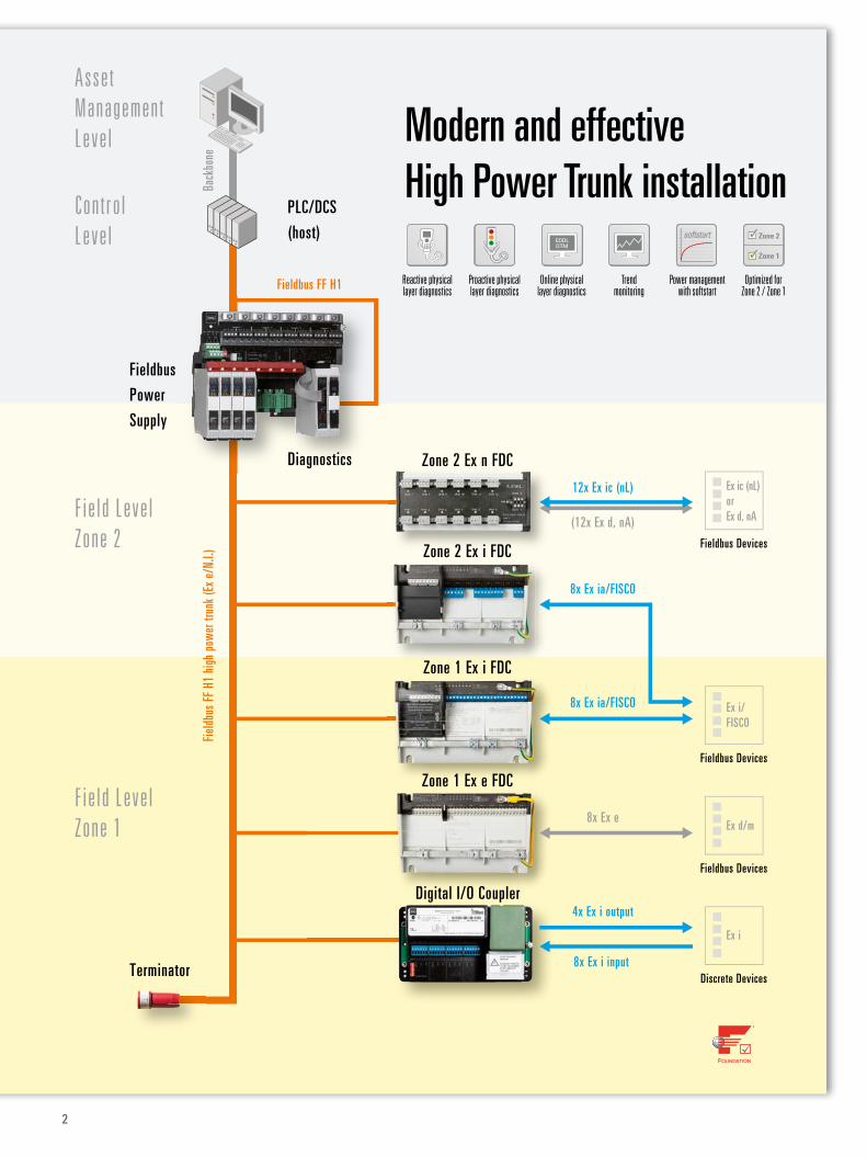
The Zone 1 Ex e Field Device Coupler connects 4 or 8 non-intrinsically safe fieldbus devices to the High Power Trunk.
The fieldbus devices in type of protection Ex d, Ex q or Ex m can each be powered with up to 41 mA. Each spur features 50 mA current limiting in order to prevent feedback effects on the trunk in the event of short circuits. A red LED per spur clearly indicates such a failure condition. Installation, wiring, enclosures, terminals and shielding etc. are designed as for the Ex i Field Device Couplers.
Power MangementAll R.STAHL Field Device Couplers feature two functionalities to lower the current con-sumption on the trunk under all conditions as much as possible:
èèThe softstart function – as soon as the trunk voltage at the couplers exceeds 16 V, the spurs are activated one after the other which results in a significantly lower inrush current during start-up for longer cable runs and more fieldbus devices per segment.
èèShort circuit limitation – in the event of multiple spur short circuits, all spurs are de-energized until the failure is eliminated. Even with multiple short circuits, the trunk is loaded with a maximum of only one short circuit current at a time.
èè for FOUNDATIONTM Fieldbus H1 or Profibus PA
èè 4 and 8 spur versions available
èè spur protection for each spur
èè power management with softstart and short circuit limitation
èè LED indication of faults on each spur
èè switchable termination on board
èè screw or spring clamp terminals
Highlights
Ex ic (nL) orEx d nA
TC/RTD
Ex d/m
Ex i
Ex n FDC
Zone 1 Ex e FDCEx e FDC
Digital I/OCoupler
T
Zone
1Zo
ne 2
Non-
Ex
Ex i FDC
Ex i FDC
Fieldbus Power Supply
DiagnosisModule
PLC/DCS(host)
PC
Field device couplerfor Zone 1 installations and Ex d/m/q devices
Proactive physical layer diagnostics
Trend monitoring
Reactive physical layer diagnostics
Optimized for Zone 2 / Zone 1
Power management with softstart
softstart
Online physical layer diagnostics
EDDLDTM
WebCode 9411B
8
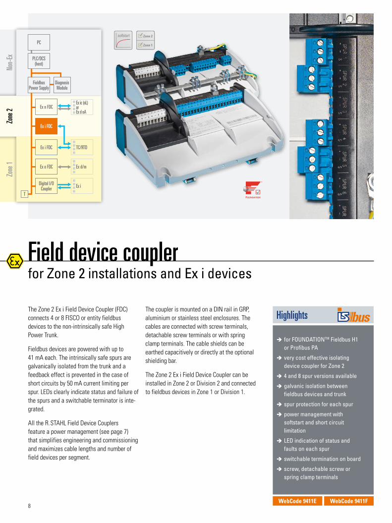
The Zone 2 Ex i Field Device Coupler (FDC) connects 4 or 8 FISCO or entity fieldbus devices to the non-intrinsically safe High Power Trunk.
Fieldbus devices are powered with up to 41 mA each. The intrinsically safe spurs are galvanically isolated from the trunk and a feedback effect is prevented in the case of short circuits by 50 mA current limiting per spur. LEDs clearly indicate status and failure of the spurs and a switchable terminator is inte-grated.
All the R.STAHL Field Device Couplers feature a power management (see page 7) that simplifies engineering and commissioning and maximizes cable lengths and number of field devices per segment.
The coupler is mounted on a DIN rail in GRP, aluminium or stainless steel enclosures. The cables are connected with screw terminals, detachable screw terminals or with spring clamp terminals. The cable shields can be earthed capacitively or directly at the optional shielding bar.
The Zone 2 Ex i Field Device Coupler can be installed in Zone 2 or Division 2 and connected to fieldbus devices in Zone 1 or Division 1.
èè for FOUNDATIONTM Fieldbus H1 or Profibus PA
èè very cost effective isolating device coupler for Zone 2
èè 4 and 8 spur versions available
èè galvanic isolation between fieldbus devices and trunk
èè spur protection for each spur
èè power management with softstart and short circuit limitation
èè LED indication of status and faults on each spur
èè switchable termination on board
èè screw, detachable screw or spring clamp terminals
Highlights
Ex ic (nL) orEx d nA
TC/RTD
Ex d/m
Ex i
Ex n FDC
Ex e FDC
Digital I/OCoupler
T
Zone
1Zo
ne 2
Non-
Ex
Zone 2 Ex i FDCEx i FDC
Ex i FDC
Fieldbus Power Supply
DiagnosisModule
PLC/DCS(host)
PC
Field device couplerfor Zone 2 installations and Ex i devices
Proactive physical layer diagnostics
Trend monitoring
Reactive physical layer diagnostics
Optimized for Zone 2 / Zone 1
Power management with softstart
softstart
Online physical layer diagnostics
EDDLDTM
Proactive physical layer diagnostics
Trend monitoring
Reactive physical layer diagnostics
Optimized for Zone 2 / Zone 1
Power management with softstart
softstart
Online physical layer diagnostics
EDDLDTM
WebCode 9411E WebCode 9411F
9
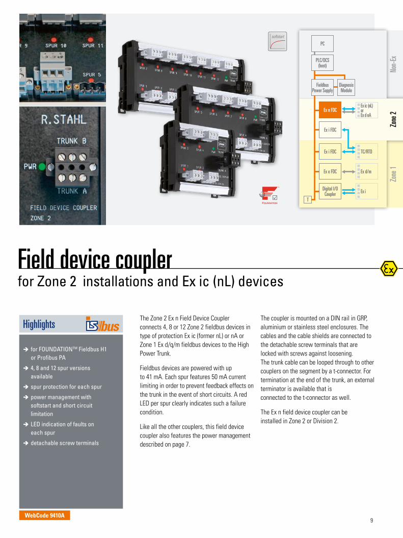
The Zone 2 Ex n Field Device Coupler connects 4, 8 or 12 Zone 2 fieldbus devices in type of protection Ex ic (former nL) or nA or Zone 1 Ex d/q/m fieldbus devices to the High Power Trunk.
Fieldbus devices are powered with up to 41 mA. Each spur features 50 mA current limiting in order to prevent feedback effects on the trunk in the event of short circuits. A red LED per spur clearly indicates such a failure condition.
Like all the other couplers, this field device coupler also features the power management described on page 7.
The coupler is mounted on a DIN rail in GRP, aluminium or stainless steel enclosures. The cables and the cable shields are connected to the detachable screw terminals that are locked with screws against loosening. The trunk cable can be looped through to other couplers on the segment by a t-connector. For termination at the end of the trunk, an external terminator is available that is connected to the t-connector as well.
The Ex n field device coupler can be installed in Zone 2 or Division 2.
èè for FOUNDATIONTM Fieldbus H1 or Profibus PA
èè 4, 8 and 12 spur versions available
èè spur protection for each spur
èè power management with softstart and short circuit limitation
èè LED indication of faults on each spur
èè detachable screw terminals
Highlights
Ex ic (nL) orEx d nA
TC/RTD
Ex d/m
Ex i
Zone 2Ex n FDCEx n FDC
Ex e FDC
Digital I/OCoupler
T
Zone
1Zo
ne 2
Non-
Ex
Ex i FDC
Ex i FDC
Fieldbus Power Supply
DiagnosisModule
PLC/DCS(host)
PC
Field device couplerfor Zone 2 installations and Ex ic (nL) devices
Proactive physical layer diagnostics
Trend monitoring
Reactive physical layer diagnostics
Optimized for Zone 2 / Zone 1
Power management with softstart
softstart
Online physical layer diagnostics
EDDLDTM
WebCode 9410A
10
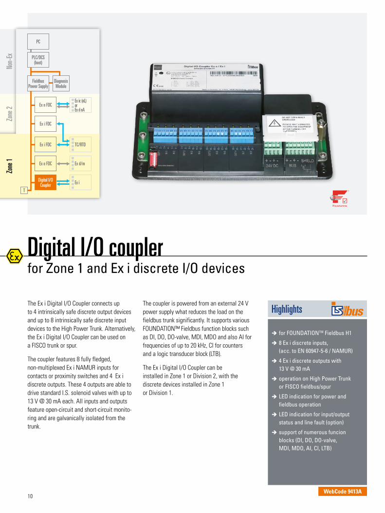
The Ex i Digital I/O Coupler connects up to 4 intrinsically safe discrete output devices and up to 8 intrinsically safe discrete input devices to the High Power Trunk. Alternatively, the Ex i Digital I/O Coupler can be used on a FISCO trunk or spur.
The coupler features 8 fully fledged, non-multiplexed Ex i NAMUR inputs for contacts or proximity switches and 4 Ex i discrete outputs. These 4 outputs are able to drive standard I.S. solenoid valves with up to 13 V @ 30 mA each. All inputs and outputs feature open-circuit and short-circuit monito-ring and are galvanically isolated from the trunk.
The coupler is powered from an external 24 V power supply what reduces the load on the fieldbus trunk significantly. It supports various FOUNDATION™ Fieldbus function blocks such as DI, DO, DO-valve, MDI, MDO and also AI for frequencies of up to 20 kHz, CI for counters and a logic transducer block (LTB).
The Ex i Digital I/O Coupler can be installed in Zone 1 or Division 2, with the discrete devices installed in Zone 1 or Division 1.
èè for FOUNDATIONTM Fieldbus H1
èè 8 Ex i discrete inputs, (acc. to EN 60947-5-6 / NAMUR)
èè 4 Ex i discrete outputs with 13 V @ 30 mA
èè operation on High Power Trunk or FISCO fieldbus/spur
èè LED indication for power and fieldbus operation
èè LED indication for input/output status and line fault (option)
èè support of numerous funcion blocks (DI, DO, DO-valve, MDI, MDO, AI, CI, LTB)
Highlights
Ex ic (nL) orEx d nA
TC/RTD
Ex d/m
Ex i
Ex n FDC
Ex e FDC
Digital I/OCoupler
T
Zone
1Zo
ne 2
Non-
Ex
Ex i FDC
Ex i FDC
Fieldbus Power Supply
DiagnosisModule
PLC/DCS(host)
PC
Digital I/O coupler for Zone 1 and Ex i discrete I/O devices
WebCode 9413A
11
Highlights
Fieldbus accessoriesfor hazardous areas and harsh environments
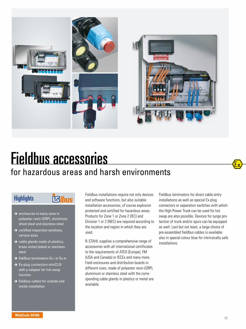
Fieldbus installations require not only devices and software functions, but also suitable installation accessories; of course explosion protected and certified for hazardous areas. Products for Zone 1 or Zone 2 (IEC) and Division 1 or 2 (NEC) are required according to the location and region in which they are used.
R.STAHL supplies a comprehensive range of accessories with all international certificates to the requirements of ATEX (Europe), FM (USA and Canada) or IECEx and many more. Field enclosures and distribution boards in different sizes, made of polyester resin (GRP), aluminium or stainless steel with the corre-sponding cable glands in plastics or metal are available.
Fieldbus terminators for direct cable entry installations as well as special Ex-plug connectors or separation switches with which the High Power Trunk can be used for hot swap are also possible. Devices for surge pro-tection of trunk and/or spurs can be equipped as well. Last but not least, a large choice of pre-assembled fieldbus cables is available also in special colour blue for intrinsically safe installations.
èè enclosures in many sizes in polyester resin (GRP), aluminium, sheet steel and stainless steel
èè certified inspection windows, various sizes
èè cable glands made of plastics, brass nickel plated or stainless steel
èè fieldbus terminators Ex i or Ex m
èè Ex-plug connectors miniCLIX with y-adapter for hot-swap function
èè fieldbus cables for outside and inside installation
WebCode 9418A

12
Fieldbus engeneering customized solutions to meet your requirements
42
3
1
1 Fieldbus junction boxes for mega project in India2 Zone 1 Fieldstation with fieldbus and remote I/O3 Very compact 16 spur design for Zone 1 Ex i FDC
with maintenance switch and inspection windows4 Customized solution integrating remote I/O,
fieldbus FF H1 and valve islands
Today, differing applications and diverse custo-mer requirements lead to simultaneous use of several fieldbuses. In addition, mechanical concepts matched to the required tasks and ambient conditions are required. R.STAHL, together with its customers, plans the selection of the components, bus systems and field-compliant enclosures, matched to the required tasks and ambient conditions. We are able to supply the optimum all-in solution for the interface between field devices and automation system: for conventional sensors and actuators, for HART field devices, for field-bus devices, and for any combination of them.
Integration of third party components like e.g. solenoid valve islands and special designs for extreme ambient temperatures is our daily work. And of course, all customized R.STAHL system solutions come certified for installation in the respective hazardous area – ready to run!
èè more than 30 years of experience with system solutions for haza- dous areas
èè one of the largest product offerings for installations in Zone 1, Zone 2, Div. 1 and Div. 2
èè highly qualified personnel for fiel- bus and remote I/O engineering
èè inspection of installations with FF H1, PROFIBUS and Ethernet
èè testing and documentation for GAMP and FDA
èè customer seminars and training for explosion protection
èè after sales support, hotline and on-site support
èè international certification network for all explosion protection topics
Highlights
www.fieldbus-solutions.com
13
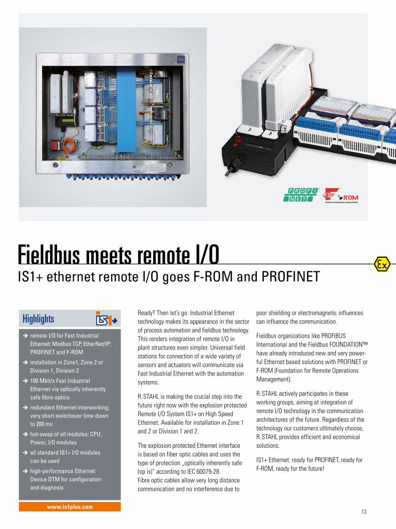
Highlightsèè remote I/O for Fast Industrial Ethernet: Modbus TCP, EtherNet/IP; PROFINET and F-ROM
èè installation in Zone1, Zone 2 or Division 1, Division 2
èè 100 Mbit/s Fast Industrial Ethernet via optically inherently safe fibre-optics
èè redundant Ethernet interworking; very short switchover time down to 200 ms
èè hot-swap of all modules: CPU, Power, I/O modules
èè all standard IS1+ I/O modules can be used
èè high-performance Ethernet Device DTM for configuration and diagnosis
Ready? Then let’s go: Industrial Ethernet technology makes its appearance in the sector of process automation and fieldbus technology. This renders integration of remote I/O in plant structures even simpler. Universal field stations for connection of a wide variety of sensors and actuators will communicate via Fast Industrial Ethernet with the automation systems.
R.STAHL is making the crucial step into the future right now with the explosion protected Remote I/O System IS1+ on High Speed Ethernet. Available for installation in Zone 1 and 2 or Division 1 and 2.
The explosion protected Ethernet interface is based on fiber optic cables and uses the type of protection „optically inherently safe (op is)” according to IEC 60079-28. Fibre optic cables allow very long distance communication and no interference due to
poor shielding or electromagnetic influences can influence the communication.
Fieldbus organizations like PROFIBUS International and the Fieldbus FOUNDATION™ have already introduced new and very power-ful Ethernet based solutions with PROFINET or F-ROM (Foundation for Remote Operations Management).
R.STAHL actively participates in these working groups, aiming at integration of remote I/O technology in the communication architectures of the future. Regardless of the technology our customers ultimately choose, R.STAHL provides efficient and economical solutions.
IS1+ Ethernet: ready for PROFINET, ready for F-ROM, ready for the future!
Fieldbus meets remote I/OIS1+ ethernet remote I/O goes F-ROM and PROFINET
www.is1plus.com
14
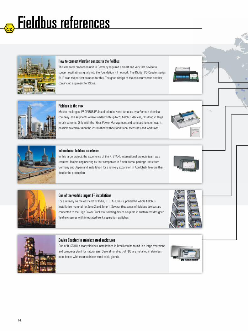
Fieldbus references
One of the world‘s largest FF installationsFor a refinery on the east cost of India, R. STAHL has supplied the whole fieldbus
installation material for Zone 2 and Zone 1. Several thousands of fieldbus devices are
connected to the High Power Trunk via isolating device couplers in customized designed
field enclosures with integrated trunk separation switches.
International fieldbus excellenceIn this large project, the experience of the R. STAHL international projects team was
required: Project engineering by four companies in South Korea, package units from
Germany and Japan and installation for a refinery expansion in Abu Dhabi to more than
double the production.
How to connect vibration sensors to the fieldbusThis chemical production unit in Germany required a smart and very fast device to
convert oscillating signals into the Foundation H1 network. The Digital I/O Coupler series
9413 was the perfect solution for this. The good design of the enclosures was another
convincing argument for ISbus.
Fieldbus to the maxMaybe the largest PROFIBUS PA installation in North America by a German chemical
company. The segments where loaded with up to 20 fieldbus devices, resulting in large
inrush currents. Only with the ISbus Power Management and softstart function was it
possible to commission the installation without additional measures and work load.
Device Couplers in stainless steel enclosuresOne of R. STAHL‘s many fieldbus installations in Brazil can be found in a large treatment
and compress plant for natural gas. Several hundreds of FDC are installed in stainless
steel boxes with even stainless steel cable glands.
Proactive physical layer diagnostics
Trend monitoring
Reactive physical layer diagnostics
Optimized for Zone 2 / Zone 1
Power management with softstart
softstart
Online physical layer diagnostics
EDDLDTM
15
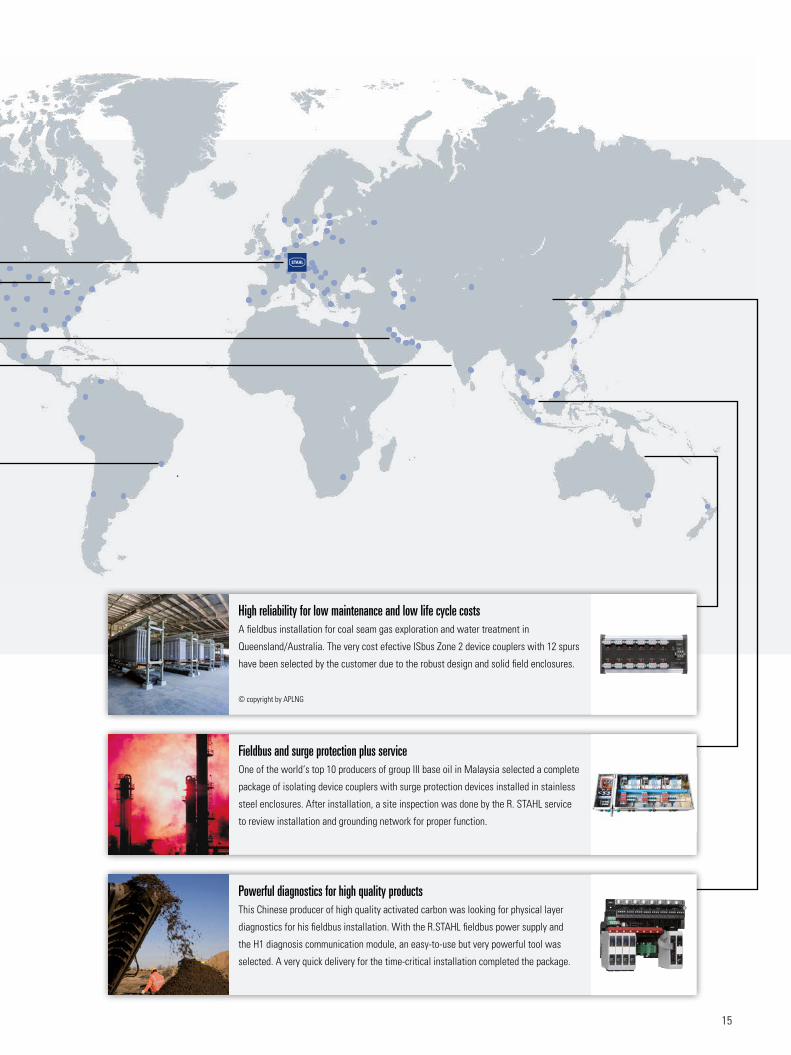
Fieldbus and surge protection plus serviceOne of the world‘s top 10 producers of group III base oil in Malaysia selected a complete
package of isolating device couplers with surge protection devices installed in stainless
steel enclosures. After installation, a site inspection was done by the R. STAHL service
to review installation and grounding network for proper function.
High reliability for low maintenance and low life cycle costsA fieldbus installation for coal seam gas exploration and water treatment in
Queensland/Australia. The very cost efective ISbus Zone 2 device couplers with 12 spurs
have been selected by the customer due to the robust design and solid field enclosures.
© copyright by APLNG
Powerful diagnostics for high quality productsThis Chinese producer of high quality activated carbon was looking for physical layer
diagnostics for his fieldbus installation. With the R.STAHL fieldbus power supply and
the H1 diagnosis communication module, an easy-to-use but very powerful tool was
selected. A very quick delivery for the time-critical installation completed the package.
R.STAHL
Am Bahnhof 30,
74638 Waldenburg, Germany
T +49 7942 943-0
F +49 7942 943-4333
www.stahl.de
ID 102617
2014-09 / EN-04 - Printed in Germany
ISbus videos


![Profibus PA Fieldbus Display [ Revision 2 ] and Fieldbus ... Instruments... · Profibus PA Fieldbus Display [ Revision 2 ] and Fieldbus Indicator Fieldbus Interface Guide. ... Siemens](https://img.pdfslide.us/doc/110x75/5b2fe38e7f8b9ae16e8da83d/profibus-pa-fieldbus-display-revision-2-and-fieldbus-instruments.jpg)