Embed Size (px)
Citation preview
Field Wire Conversion Module for Modicon B804-116 to 1756-OA16 orB824-016 to 1756-OB16E(Cat 1492-CM800-LD002)
10000021853 (Version 00)Printed in Germany
Local language (French, Italian, German & Spanish) versions of this document can be downloaded by going to www.ab.com. In the left margin click on Publications Library and Literature Library. In the Search Area (right margin), Search by Catalog Number and in the Search box type in the catalog number of the conversion system component.
I. Module Description
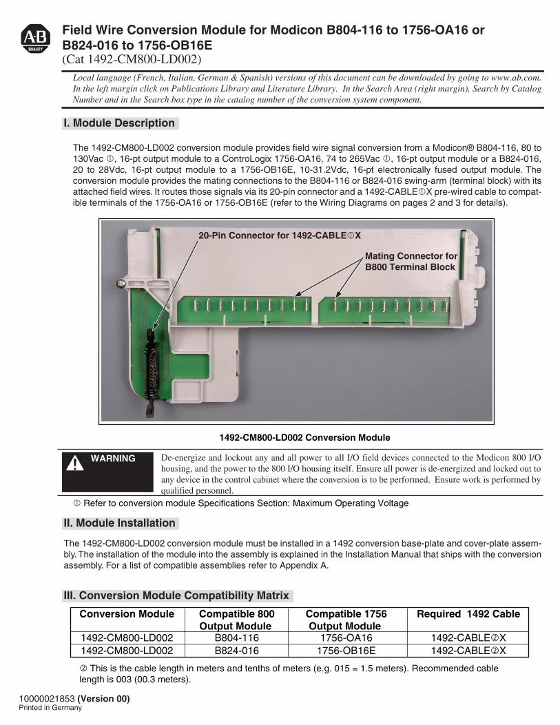
The 1492-CM800-LD002 conversion module provides field wire signal conversion from a Modicon® B804-116, 80 to 130Vac , 16-pt output module to a ControLogix 1756-OA16, 74 to 265Vac , 16-pt output module or a B824-016, 20 to 28Vdc, 16-pt output module to a 1756-OB16E, 10-31.2Vdc, 16-pt electronically fused output module. The conversion module provides the mating connections to the B804-116 or B824-016 swing-arm (terminal block) with its attached field wires. It routes those signals via its 20-pin connector and a 1492-CABLEX pre-wired cable to compat-ible terminals of the 1756-OA16 or 1756-OB16E (refer to the Wiring Diagrams on pages 2 and 3 for details).
II. Module Installation
The 1492-CM800-LD002 conversion module must be installed in a 1492 conversion base-plate and cover-plate assem-bly. The installation of the module into the assembly is explained in the Installation Manual that ships with the conversion assembly. For a list of compatible assemblies refer to Appendix A.
III. Conversion Module Compatibility Matrix
This is the cable length in meters and tenths of meters (e.g. 015 = 1.5 meters). Recommended cable length is 003 (00.3 meters).
20-Pin Connector for 1492-CABLEX
Mating Connector forB800 Terminal Block
Conversion Module Compatible 800Output Module
Compatible 1756Output Module
Required 1492 Cable
1492-CM800-LD002 B804-116 1756-OA16 1492-CABLEX1492-CM800-LD002 B824-016 1756-OB16E 1492-CABLEX
De-energize and lockout any and all power to all I/O field devices connected to the Modicon 800 I/O housing, and the power to the 800 I/O housing itself. Ensure all power is de-energized and locked out to any device in the control cabinet where the conversion is to be performed. Ensure work is performed by qualified personnel.
WARNING
1492-CM800-LD002 Conversion Module
Refer to conversion module Specifications Section: Maximum Operating Voltage
(2)10000021853 (Version 00)
IV. Conversion Module Wiring Diagram
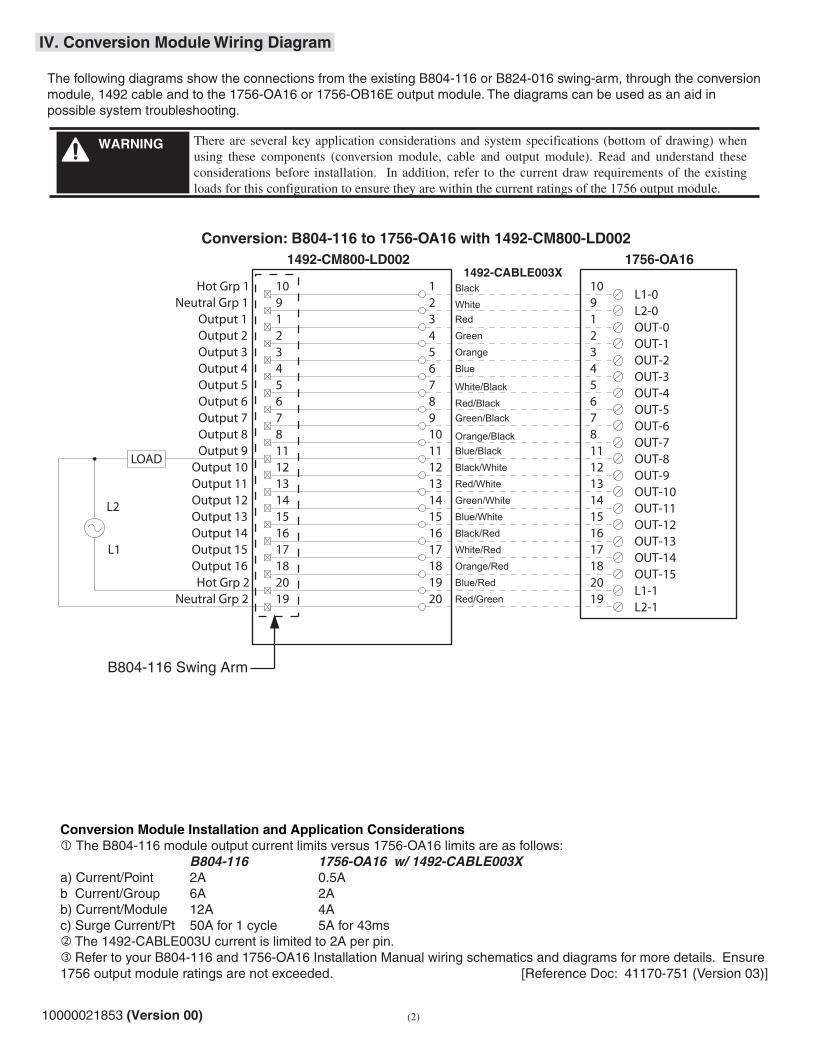
The following diagrams show the connections from the existing B804-116 or B824-016 swing-arm, through the conversion module, 1492 cable and to the 1756-OA16 or 1756-OB16E output module. The diagrams can be used as an aid in possible system troubleshooting.
Conversion Module Installation and Application Considerations The B804-116 module output current limits versus 1756-OA16 limits are as follows: B804-116 1756-OA16 w/ 1492-CABLE003Xa) Current/Point 2A 0.5Ab Current/Group 6A 2Ab) Current/Module 12A 4Ac) Surge Current/Pt 50A for 1 cycle 5A for 43ms
1756-OA161492-CABLE003X
1492-CM800-LD002
Conversion: B804-116 to 1756-OA16 with 1492-CM800-LD002
B804-116 Swing Arm
The 1492-CABLE003U current is limited to 2A per pin. Refer to your B804-116 and 1756-OA16 Installation Manual wiring schematics and diagrams for more details. Ensure 1756 output module ratings are not exceeded. [Reference Doc: 41170-751 (Version 03)]
10L1-0
OUT-01
OUT-12
OUT-23
OUT-34
OUT-45
OUT-56
OUT-67
OUT-78
OUT-811
OUT-912
OUT-1013
OUT-1114
OUT-1215
OUT-1316
OUT-1417
OUT-1518
Black
WhiteRed
Green
Orange
Blue
White/Black
Red/BlackGreen/Black
Orange/BlackBlue/Black
Black/White
Red/White
Green/White
Blue/White
Black/Red
White/Red
Orange/Red
Blue/Red
10 19 21 32 43 54 65 76 87 98 1011 1112 1213 131415 1516 1617 1718 1820 1919 20
14
Red/GreenL1-1
20
9L2-0
19L2-1
LOAD
L1
L2
Hot Grp 1
Output 13
Output 15Output 14
Output 16
Neutral Grp 2
Output 5
Output 7Output 6
Output 8
Output 1
Output 3Output 2
Output 4
Output 9
Output 11Output 10
Output 12
Hot Grp 2
Neutral Grp 1
There are several key application considerations and system specifications (bottom of drawing) when using these components (conversion module, cable and output module). Read and understand these considerations before installation. In addition, refer to the current draw requirements of the existing loads for this configuration to ensure they are within the current ratings of the 1756 output module.
WARNING
(3)10000021853 (Version 00)
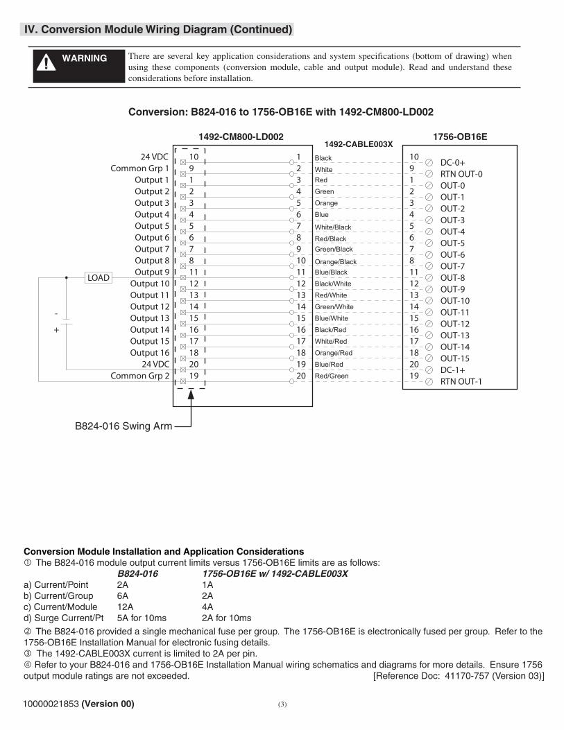
IV. Conversion Module Wiring Diagram (Continued)
1756-OB16E1492-CABLE003X
1492-CM800-LD002
Conversion: B824-016 to 1756-OB16E with 1492-CM800-LD002
B824-016 Swing Arm
10 19 21 32 43 54 65 76 87 98 1011 1112 1213 131415 1516 1617 1718 1820 1919 20
14
24 VDC
Output 13
Output 15Output 14
Output 16
Common Grp 2
Output 5
Output 7Output 6
Output 8
Output 1
Output 3Output 2
Output 4
Output 9
Output 11Output 10
Output 12
24 VDC
Common Grp 110
DC-0+
OUT-01
OUT-12
OUT-23
OUT-34
OUT-45
OUT-56
OUT-67
OUT-78
OUT-811
OUT-912
OUT-1013
OUT-1114
OUT-1215
OUT-1316
OUT-1417
OUT-1518
Black
WhiteRed
Green
Orange
Blue
White/Black
Red/BlackGreen/Black
Orange/BlackBlue/Black
Black/White
Red/White
Green/White
Blue/White
Black/Red
White/Red
Orange/Red
Blue/Red
Red/GreenDC-1+
20
9RTN OUT-0
19RTN OUT-1
+
-
LOAD
Conversion Module Installation and Application Considerations The B824-016 module output current limits versus 1756-OB16E limits are as follows: B824-016 1756-OB16E w/ 1492-CABLE003Xa) Current/Point 2A 1Ab) Current/Group 6A 2Ac) Current/Module 12A 4Ad) Surge Current/Pt 5A for 10ms 2A for 10ms
The B824-016 provided a single mechanical fuse per group. The 1756-OB16E is electronically fused per group. Refer to the 1756-OB16E Installation Manual for electronic fusing details. The 1492-CABLE003X current is limited to 2A per pin. Refer to your B824-016 and 1756-OB16E Installation Manual wiring schematics and diagrams for more details. Ensure 1756 output module ratings are not exceeded. [Reference Doc: 41170-757 (Version 03)]
There are several key application considerations and system specifications (bottom of drawing) when using these components (conversion module, cable and output module). Read and understand these considerations before installation.
WARNING
10000021853 (Version 00)Printed in Germany
Article No. 4351850000
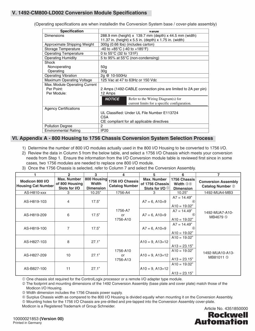
V. 1492-CM800-LD002 Conversion Module Specifications
(Operating specifications are when installedin the Conversion System base / cover-plate assembly)
VI. Appendix A - 800 Housing to 1756 Chassis Conversion System Selection Process
1) Determine the number of 800 I/O modules actually used in the 800 I/O Housing to be converted to 1756 I/O.2) Review the data in Column 5 from the below table, and select a 1756 I/O Chassis which meets your conversion
needs from Step 1. Ensure the information from the I/O Conversion module table is reviewed first since in some cases, two 1756 modules are needed to replace one 800 I/O module.
3) Once the 1756 Chassis is selected, refer to Column 7 and select the Conversion Assembly.
One chassis slot required for the ControlLogix processor or a remote I/O adapter type module. The footprint and mounting dimensions of the 1492 Conversion Assembly (base plate and cover plate) match those of the
Modicon I/O Housing. Width dimension includes the 1756 Chassis power supply. Surplus Chassis width as compared to the 800 I/O Housing is divided equally when mounting it on the Conversion Assembly. Mounting holes for the 1756 I/O Chassis are pre-drilled and pre-tapped into the Conversion Assembly cover-plate.Modicon is a Registered Trademark of Group Schneider.
Specification Value Dimensions 288.9 mm (height) x 139.7 mm (depth) x 44.5 mm (width)
11.37 in. (height) x 5.5 in. (depth) x 1.75 in. (width) Approximate Shipping Weight 300g (0.66 lbs) (includes carton) Storage Temperature -40 to +85°C (-40 to +185°F) Operating Temperature 0 to 55°C (32 to 131F) Operating Humidity 5 to 95% at 55°C (non-condensing) Shock Non-operating Operating
50g 30g
Operating Vibration 2g @ 10-500Hz Maximum Operating Voltage 125 Vac at 47 to 63Hz or 150 Vdc Max. Module Operating Current Per Point: Per Module:
2 Amps (1492-CABLE connection pins are limited to 2A per pin) 12 Amps
Agency Certifications
UL Classified: Under UL File Number E113724 CSA CE: compliant for all applicable directives
Pollution Degree 2 Environmental Rating IP20
AS-H810-xxx
AS-H819-103
AS-H819-209
AS-H819-100
AS-H827-103
AS-H827-209
AS-B827-100
Modicon 800 I/O Housing Cat Number
1492-MUA4-MB3
1492-MUA7-A10-MB4679
1492-MUA10-A13-MB81011
Conversion AssemblyCatalog Number
3
4
6
7
8
10
11
10.25”
17.5”
17.5”
17.5”
27.1”
27.1”
27.1”
10.25”A7 = 14.49”
A10 = 19.02”A7 = 14.49”
A10 = 19.02” A7 = 14.49”
A10 = 19.02”A10 = 19.02”
A13 = 23.15”A10 = 19.02”
A13 = 23.15”A10 = 19.02”
A13 = 23.15”
1756 ChassisWidth Dimension
3
A7 = 6, A10=9
A7 = 6, A10=9
A7 = 6, A10=9
A10 = 9, A13=12
A10 = 9, A13=12
A10 = 9, A13=12
1756 I/O ChassisCatalog Number
1 72 3 654
1756-A4
1756-A7or
1756-A10
1756-A10or
1756-A13
Max. Numberof 800 Housing
Slots for I/O
800 HousingWidth
Dimension
Max. Numberof 1756 Chassis
Slots for I/O
Refer to the Wiring Diagram(s) for current limits for a specific configuration.
NOTICE

CONFIDENTIAL AND PROPRIETARY INFORMATION. THIS DOCUMENT CONTAINS CONFIDENTIAL AND PROPRIETARY INFORMATION OF
ROCKWELL AUTOMATION, INC. AND MAY NOT BE USED, COPIED OR DISCLOSED TO OTHERS, EXCEPT WITH THE AUTHORIZED WRITTEN
PERMISSION OF ROCKWELL AUTOMATION, INC.
Sheet
Size Ver
Of 11
A 0010000028320Dr. DateG. USHAKOW 8-19-08
MATERIALSIZE
FOLD
TO BE DETERMINEDBY STRATEGIC PARTNER
TO BE DETERMINEDBY STRATEGIC PARTNER
TO BE DETERMINEDBY STRATEGIC PARTNER
FLAT
Note: If folding---instruction sheet number should be visible.
SPECIFICATIONS FORINSTRUCTION SHEET CREATED BY STRATEGIC PARTNER
This Instruction Sheet is Being Printed by Strategic Partner