Embed Size (px)
Citation preview

Field Top Mounted Condensing Unit
IMPORTANT Keep in store for future reference!
ED5/ED5-N INSTALLATION & OPERATIONS MANUAL

REVISION HISTORY VERSION 1.0 • New manual
This manual is specific to the field top mounted condensing unit. For standard display case, please refer to standard case installation & Operations Manual.

TABEL OF CONTENTS
GENERAL INFORMATION .................................................................................... 4 Safety Notice General Information INSTALLATION ...................................................................................................... 5 Condensing Unit Pump Evaporating Heater Pan Condensing Unit Cover START UP / OPERATION ....................................................................................... 22 Open CDU Valves ELECTRICAL ………………………………………………………………………………………………..……. 23 Wiring Diagrams OPERATION …………………………………………………….……..…………………………………….…. 25 Digital Controller APPENDIX ............................................................................................................. 28 ED5/ED5-N Electrical Data & Case Dimensions

SAFETY NOTICE All warning messages will inform you of the potential hazard; how to reduce the risk of case damage, personal injury or death; and what may happen if the instructions are not properly followed. • DANGER – Indicate[s] a hazardous situation which, if not avoided, will result in death or serious injury. • WARNING – Indicate[s] a hazardous situation which, if not avoided, could result in death or serious injury. • CAUTION – Indicate[s] a hazardous situation which, if not avoided, could result in minor or moderate injury.
GENERAL INFORMATION
GENERAL INFORMATION • STORE CONDITIONS Cases are designed to operate in an air-conditioned store that maintains a 75°F (24°C) store temperature and 55% (max) relative humidity. Case operation will be adversely affected by exposure to excessively high ambient temperatures and/or humidity. ANSI/NSF-7 Type I – Display Refrigerator / Freezer Intended for 75°F / 55%RH Ambient Application • REFRIGERATION SYSTEM OPERATION Adequate ventilation must be provided to dissipate rejected heat from the top of unit for proper performance. Clearance between top of Condensing unit covers and ceiling should be more than 30”. • EXTERIOR LOADING Do not walk on top of merchandisers. It could damage the cases and serious personal injury could occur. They are not structurally designed to support excessive external loading such as the weight of a person. Do not place heavy objects on the merchandiser. • SERIAL NUMBER LOCATION The serial number is located in left top inside of cabinets. • SHIPPING DAMAGE All equipment should be thoroughly examined for shipping damage before and during unloading. Any claim for loss or damage must be made to the carrier. The carrier will provide any necessary inspection reports and/or claim forms. Claims for obvious damage must be noted on either the freight bill or the express receipt and signed by the carrier's agent; otherwise, the carrier may refuse the claim. If damage becomes apparent after the equipment is unpacked, retain all packing materials and submit a written request to the carrier for inspection within 14 days of receipt of the equipment. • LOST/MISSING ITEMS Any claim for missing items must be made to Texaking within 48 hours of receipt of the equipment.

INSTALLATION
CONDENSING UNIT
PIPE INSULATION (2) MOUNTING SCREW (4) WASHER (4)
CABLE TIE (6)
CONDENSING UNIT
1) Open Condensing Unit Package
WARNING • Refrigeration lines are under pressure and should be depressurized before attempting to make any connections. • Always wear safety glasses and protective gloves when working with refrigerants. Contact with refrigerant may cause injury. Disconnect pipes with extreme caution. All pipes may contain liquid refrigerant under high pressure. • Avoid breathing refrigerant and lubrication vapor or mist. Exposure may irritate eyes, nose and throat. If accidental system discharge occurs, ventilate work area before resuming service. • Be sure that any room where you are working is thoroughly ventilated, especially if a leak is suspected. Refrigerant vapor is hazardous to your health and can cause death.
INSTALLATION
a b d c
Front View After Mounting Rear View After Mounting
CONDENSING UNIT
2) Mount Condensing Unit on top of the case.
• Place Condensing Unit on the top of the case, then use provided mounting screws and washers to secure. • Make sure to mount condensing unit at the corresponding location, so that the quick connects are facing
each others.
b
c
d
a
a
b d
c
Quick Connects

INSTALLATION
3) Wiring-Power
DO NOT ENERGIZE POWER DURING THE INSTALLATION Step 1: Locate lead wire for Condensing Unit at the top of the case, next to electrical box. It should be 2 yellows (male and female connectors), red, black, and green. Step 2: Remove screws to open the electrical box cover.
1
2
ELECTRONIC UNIT CONTROLLER (EUC)
ELECTRICAL BOX COVER
3
Step 3: Navigate wires through the hole of electrical box of the Condensing Unit.
CONDENSING UNIT

INSTALLATION
Step 5: Tighten the Conduit Washer to anchor the lead wire to the electrical box of condensing unit.
TO ELECTRONIC UNIT CONTROLLER (EUC) (YELLOW-MALE) (YELLOW-FEMALE)
TO CONTACTOR (BLACK, RED)
TO GROUND TERMINAL (GREEN)
CONDUIT
CONDUIT WASHER
CONDENSING UNIT
5
4
CONTACTOR
GROUND TERMINAL
BLACK
Step 4: Connect power supply wires (black and red) to the contactor, and green wire to the ground terminal.

INSTALLATION
Step 3: Disconnect #14(yellow) and #17(yellow) terminal connection.
Step 1: Pop out the controller bracket. Step 2: Locate terminal #14(yellow) and #17(yellow) connection of EUC.
1
2
4) Wiring-EUC
CONTROLLER BRACKET
EUC
CONDENSING UNIT
3
#17 #14

INSTALLATION
TO ELECTRONIC UNIT CONTROLLER (EUC) (YELLOW-MALE), (YELLOW-FEMALE)
#17 #14
Step 4: Find male and female yellow wires from the conduit. Connect yellow-female wire to #17 male terminal, and yellow-male wire to #14 female terminal.
4
Step 5: Complete wiring of EUC. Close the controller bracket and electrical box cover.
YELLOW YELLOW
5
#17 (EUC) #14 (EUC) YELLOW YELLOW
CONDENSING UNIT
Before wiring EUC After wiring EUC

INSTALLATION
Step 1: Find quick connects on the back of the unit.
5) Quick Connects
CONDENSING UNIT
Step 5: Use piece of insulation provided to cover quick connect coupling of the suction pipe. Tighten insulation using provided cable tie.
Step 2: Mount the condensing unit with quick connects facing each other.
Step 3: Remove the quick connects cover.
Step 4: Align and pre-lubricate the quick connects. Tighten coupling connections with hand first. Use a torque wrench to tighten the quick connect couplings until seated. No thread should be visible for complete seal. (Leak test required) 2
3
4 CDU Unit
CDU Unit
Unit
CDU Unit
5

INSTALLATION
2) Assemble T-trap to the case.
1 3 2
Step 1: Tighten T-trap to the drain at the bottom of the case. Step 2: Assemble T-trap adaptor and T-trap hose. Step 3: Run T-trap hose through the base to the desired pump location.
1) Find Pump and T-Trap assembly parts.
T- TRAP T- TRAP ADAPTOR
PUMP PUMP BUCKET
PUMP ADAPTOR T-TRAP HOSE (4ft) CABLE TIES
PUMP
Closed with drain plug

INSTALLATION
3) Pump installation. PUMP HOSE
4
BACK OF THE CASE
Step 4: Tighten pump adaptor to the pump, and install pump hose from the pump to the top of the case, secure at the back of the case using screw-cable tie.
Step 5: Locate the pump bucket at the desired pump location, and place the pump inside. Step 6: Install T-trap hose from T-trap to the pump bucket, and secure using cable ties. Make sure T-trap hose is not directed upward, so drain water can flow to the pump bucket. Step 7: Make sure T-trap hose is 2 inches above from the base of the pump bucket, to avoid blocking the drain path.
PUMP
5
6
PUMP HOSE
T-TRAP HOSE
7
2”
T-TRAP HOSE PUMP
HOSE

INSTALLATION
Step 8: Make sure to open the breath nose (red cap) from the power cord. Step 9: Plug power cord to the pump receptacle, which can be found at the bottom left corner of the case.
9
8
PUMP

INSTALLATION
1) Find Condensate Pan Heater parts
PUMP HOSE
SCREW (4) CONDENSATE PAN HEATER
HOSE CLAMP
Step 1: Find 206mm X 508mm condensate pan heater mounting holes on top of the case. Step 2: Fasten the condensate pan heater. Step 3: Using hose clamp, tighten the pump hose to the pan heater inlet.
2) Install Condensate Pan Heater
1
2 3
PUMP HOSE
CONDENSATE PAN HEATER
Length of case 4ft 6ft 8ft 12ft
# of pan heater 1 2 2 3
Condensate Pan Heater

INSTALLATION
Step 5: Use available hole to enter electrical box.
Step 6: Connect wires as shown above. Use circled three terminals for the condensate pan heaters wiring.
Step 4: Find power supply wire of the condensate pan heater. Make sure folk terminals are applied to black and red wires.
3) Wiring Condensate Pan Heater.
4
5
CONDENSATE PAN HEATER
RED
BLACK
GREEN

INSTALLATION
NOTE: different models has different number of Condensate Pan Heater, so it is very important to divide water path equally.
4) Using Tee adapter for multiple path
CONDENSATE PAN HEATER
Length of case 4ft 6ft 8ft 12ft
# of pan heater 1 2 2 3
# of Tee Adapter 0 1 1 2
Model with 3 Condensate Pan Heaters
Model with 2 Condensate Pan Heaters

INSTALLATION CONDENSING UNIT COVER
1) Install Supports. CDU COVER SUPT LH SIDE
CDU COVER SUPT RH SIDE CDU COVER SUPT FRT
CDU COVER SUPT FRT (OPTIONAL)
“A”
“B”
“A” “B”
STEP 1: Install CDU COVER SUPT LH SIDE and CDU COVER SUPT RH SIDE using embosses on foam body top cover. (“A”)
STEP 2: Install CDU COVER SUPT FRT on the CANOPY SUPT BRKT. (“B”) Shoulder screws need to be installed on CDU COVER SUPT FRT for 8, 12ft and 4, 5door cases.
CANOPY SUPT BRKT

INSTALLATION
2) Install CDU cover side.
CDU COVER SIDE RH CDU COVER SIDE LH
“C”
CDU COVER FRONT
“C”
CONDENSING UNIT COVER
STEP 3: Install CDU COVER SIDE LH and CDU COVER SIDE RH using embosses on foam body top cover. Fasten CDU COVER SIDE LH and CDU COVER SIDE RH to CDU COVER SUPT LH SIDE and CDU COVER SUPT.
STEP 4: Secure the CDU COVER FRONT to the CDU COVER SUPT FRT and CDU COVER SIDES. Fasten CDU COVER FRONT to CDU COVER SIDE.

“D”
INSTALLATION
3) Install CDU cover front.
“D”
CDU CORNER BRKT
CDU COVER FRONT
CONDENSING UNIT COVER
STEP 5: Install CDU CORNER BRKT to secure CDU COVER FRONT to CDU COVER SIDE. Optional CDU COVER REAR: Install CDU CORNER CRKT to secure CDU COVER SIDE to optional CDU COVER REAR.
“D”

INSTALLATION
4) Optional: CDU Cover Rear
CONDENSING UNIT COVER
CDU COVER REAR
Optional CDU COVER REAR: Secure CDU COVER REAR to the CDU COVER SUPT FRT by lifting the cover rear and inserting shoulder screw through large hole. Then push it down to secure. Fasten CDU COVER SIDE to CDU COVER REAR.

START UP / OPERATION
1) Open CDU valves.
Step 1: Locate two valves at the CDU. Use appropriate sized wrench to open both valves.

ELCTRICAL
WIRING DIAGRAM Junction Box mounted top
FIELD WIRING • Field wiring must be sized for component amperes stamped on the data label in left top inside of case. • Electrical hookups are made to a junction box located at top of case
ED5/ED5-N Model

ELCTRICAL
Case
WIRING DIAGRAM ED5/ED5-N Model

CAREL PJEZ CONTROLLER
Parameter Description Type min max UOM. Factory Recommended
Settings
MODEL: ED5 PS Password F 0 200 - 22 /5 Select °C / °F ( 0 = °C; 1 = °F) C 0 1 - 1 St Set point S r1 r2 °C/°F 28 rd Control differential F 0.0 19.0 °C/°F 7
d0 Type of defrost (0= heater; 1= hot gas; 2=heater by time; 3= hot gas by time; 4= heater by time with temp. cont.)
C 0 4 - 0
dI Interval between two defrosts F 0 199 h/min (see dC) 4 dt End defrost temperature F -50 130 °C/°F 48 dP Max. or effective defrost duration F 1 199 min/s (see dC) 45
dC Time base (for defrost only; 0= h/min; 1= min/s) C 0 1 - 0
AL Low temperature alarm threshold/deviation (AL= 0; alarm disabled)
F -50 250 °C/°F -10
AH High temperature alarm threshold/deviation (AH= 0; alarm disabled)
F -50 250 °C/°F 20
Ad Low and high temperature alarm delay C 0 199 min 30
FACTORY RECOMMENDED CONTROL SETTINGS
OPERATION
1) Recommended control settings
DIGITAL CONTROLLER

Setting the set point (desired temperature) • press SET for 1 s, the set value will start flashing after a few moments; • increase or decrease the value using UP or DOWN; • press SET to confirm the new value.
Switching the device ON/OFF Press UP for more than 3 s. The control and defrost algorithms are now disabled and the instrument displays the message “OFF” alternating with the temperature read by the set probe.
Manual defrost Press for DOWN more than 3 s (the defrost starts only the temperature conditions are valid).
Access and setting type F (frequent) and type C (configuration) parameters 1. press SET for 3 s (the display will show “PS”); 2. • to access the type F and C parameter menu, enter the password “22” using UP/DOWN; • to access the F parameter menu only, press SET (without entering the password); scroll inside the parameter menu using UP/DOWN; 3. • to display/set the values of the parameter displayed, press SET, then UP/DOWN and finally SET to confirm the changes (returning to the parameter menu). To save all the new values and exit the parameter menu, press SET for 3 s; To exit the menu without saving the changed values (exit by timeout) do not press any button for at least 60 s.
For more detail instruction for the controller, please visit CAREL’s website, and look for the user manual.
Wiring Diagram
OPERATION
2) Setting the parameters and display functions. Refer to controller manual for more detail.
DIGITAL CONTROLLER
OPERATION
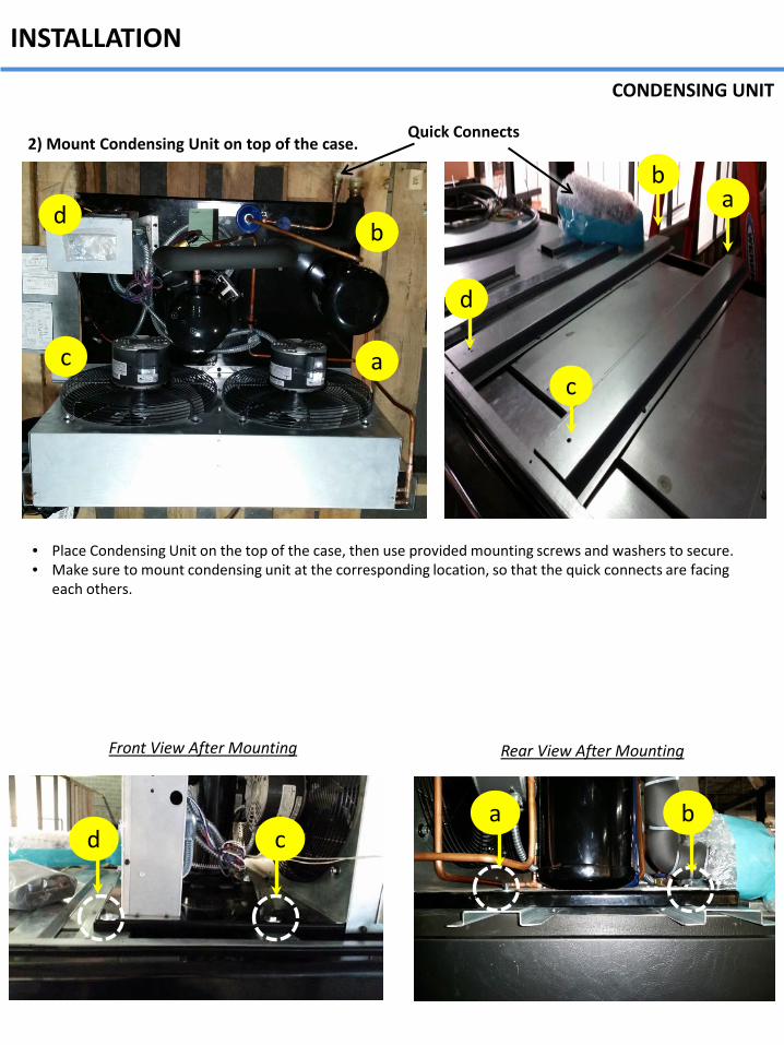
3) Table of parameters Refer to controller manual for more detail.
DIGITAL CONTROLLER

Condensing Unit
ED5 MODELS APPENDIX Top Field Mounted Condensing Unit
4' 6' 8' 12' Condensing Unit Model FFAP-015Z-CFV-072 FFAP-022Z-CFV-071 FFAP-022Z-CFV-071 FFAP-032Z-CFV-071 Refrigerant Charge (R404a, lbs) 4.0 6.0 8.0 10.0
Electrical Rating 115V/208V-1PH-60Hz : Red & Black power, white neutral, green ground MOCP (amps) 1 25 40 45 60 MCA (amps) 2 19.5 34.1 40.1 52.1 Notes: 1. MOCP: Maximum over-current protection, Including condensing unit and condensate removal system. 2. MCA: Minimum circuit ampacity , Including condensing unit and condensate removal system
Lighting Data
Fans 4' 6' 8' 12' Fans Per Case 2 3 3 4 Volts 120 120 120 120 Amps 0.6 0.9 0.9 1.2 Watts 40 60 60 80
LED Lighting 4' 6' 8' 12'
Lights Per Row 1 2 2 3
Light Length 4' 3' 4' 4'
Canopy Amps 0.24 0.36 0.48 0.72 Watts 28.8 43.2 57.6 86.4
Shelf Amps 0.12 0.18 0.24 0.36 Watts 14.4 21.6 28.8 43.2
Refrigeration Data
Defrost Data
Evaporator (°F) 26 Discharge Air (°F) 32 Superheat Set point at Bulb (°F) 6~8
BTUH/ft Parallel Conventional
ED5, ED5-H 1350 1450 ED5-U 1700 1800
Type Timed-Off
Frequency (Hr) 6
Electrical Data (ED5-U) Fans 4' 6' 8' 12' Fans Per Case 2 3 4 6 Volts 120 120 120 120 Amps 0.6 0.9 1.2 1.8 Watts 40 60 80 120
Electrical Data (ED5, ED5-H)

CASE DIMENSIONS
ED5 MODELS APPENDIX Top Field Mounted Condensing Unit
Case L A
4' case 48-1/16" (1221) 24" (610)
6' case 72-1/8" (1831) 45-9/16" (1157)
8' case 96-1/8" (2442) 55 15/16" (1421)
12' case 144-3/16" (3663) 80" (2031.5)
Drain Pipe (in) 1
Liquid Line (in) 3/8
Suction Line (in) 7/8
H
ED5, ED5-H 5 3/8 (135)
ED5-U 3 3/8 (85)

ED5-N MODELS APPENDIX Top Field Mounted Condensing Unit
Condensing Unit installed 4' 6' 8' 12'
Condensing Unit Model FFAP-015Z-CFV-072 FFAP-022Z-CFV-071 FFAP-022Z-CFV-071 FFAP-032Z-CFV-071 Refrigerant Charge (R404a, lbs) 4.0 6.0 8.0 10.0
Electrical Rating 115V/208V-1PH-60Hz : Red & Black power, white neutral, green ground MOCP (amps) 1 25 40 45 60 MCA (amps) 2 19.5 34.1 40.1 52.1
Notes: 1. MOCP: Maximum over-current protection, Including condensing unit and condensate removal system. 2. MCA: Minimum circuit ampacity , Including condensing unit and condensate removal system
Electrical Data
Lighting Data
Fans 4' 6' 8' 12'
Fans Per Case 2 3 3 4
Volts 120 120 120 120
Amps 0.6 0.9 0.9 1.2
Watts 40 60 60 80
Refrigeration Data
Defrost Data
Evaporator (°F) *1) 26 Discharge Air (°F) 32 Superheat Set point at Bulb (°F) 6~8
BTUH/ft *2) Parallel Conventional
1460 1560
Type Timed-Off Frequency (Hr) 6
LED Lighting 4' 6' 8' 12'
Lights Per Row 1 2 2 3
Light Length 4' 3' 4' 4'
Canopy Amps 0.24 0.36 0.48 0.72 Watts 28.8 43.2 57.6 86.4
Shelf Amps 0.12 0.18 0.24 0.36
Watts 14.4 21.6 28.8 43.2

ED5-N MODELS APPENDIX Top Field Mounted Condensing Unit
Case L A
4' case 48-1/16" (1221) 24" (610)
6' case 72-1/8" (1831) 45-9/16" (1157)
8' case 96-1/8" (2442) 55 15/16" (1421)
12' case 144-3/16" (3663) 80" (2031.5)
Drain Pipe (in) 1
Liquid Line (in) 3/8
Suction Line (in) 7/8
CASE DIMENSIONS

WARRANTY
LIMITED WARRANTY Texaking warrants to the original purchaser of every new cases to be free from defects in material and workmanship under normal use and maintenance for a period of twelve months from the date of original installation or fifteen months after shipment date from Texaking, whichever occurs first. Any parts covered by this warrant that are examined and determined by Texaking to have been defective within fourteen months from the date of original installation or seventeen months after shipment date from Texaking, whichever occurs first, shall be repaired or replaced as stated below. Texaking shall be deemed to have fully complied with its obligation under the foregoing warranties by electing either one of the following procedures, at the sole discretion of Texaking. 1. Furnishing a replacement part, freight collect, in even exchange for the returned part, freight collect. 2. Receiving the defective part, freight collect; repairing it: and returning it, freight collect
WHAT IS NOT COVERED BY THIS WARRANTY 1. To any unit or any part thereof which has been subject to accident, alteration, negligence, misuse or abuse, operation on improper voltage, or which has not been operated in accordance with the Manufacturer’s recommendation, or if the serial number of the unit has been altered, defaced, or removed. 2. When the unit, or any part thereof, is damaged by fire, flood, or other act of god. 3. To labor cost for replacement of parts, or for freight, shipping expenses, sales tax or upgrading. 4. When the operation is impaired due to improper installation. 5. When installation and startup forms are not properly complete or returned within two weeks after startup. 6. Outside the continental united states. This plan does not cover consequential damages. Manufacturer shall not be liable under any circumstances for any consequential damages, including loss of profit, additional labor cost, loss of refrigerant or food products, or injury to personnel or property caused by defective material or parts or for any delay in its performance hereunder due to causes beyond its control. The foregoing shall constitute the sole and exclusive remedy of any purchases and the sole and exclusive liability of manufacturer in connection with this product. All claims should include: Model number, the serial number of case, proof of purchase, date of installation and all pertinent information supporting the existence of the alleged defect. Any action or breach of these warranty provisions must be commenced within one year after the cause of action has accused. MAIL CLAIM TO: Texaking 1800 s. Great SW Pkwy., Grand Prairie, TX 75051 Tel: 214-723-7206 / Fax : 214-723-7215 www.turboairinc.com

1800 s. Great SW Pkwy., Grand Prairie, TX 75051 Tel: (800) 828-2706 / Fax : 214-723-7215
www.turboairinc.com.com


![WALL MOUNTED Models CONDENSING GAS BOILER DKVLT …WALL MOUNTED CONDENSING GAS BOILER PARTS, KITS & OPTIONAL ACCESSORIES An ISO 9001-2008 Certified Company P/N# 240008889, Rev. A [05/2011]](https://img.pdfslide.us/doc/110x75/5e8dd2c8d2ace20b630a7ddd/wall-mounted-models-condensing-gas-boiler-dkvlt-wall-mounted-condensing-gas-boiler.jpg)