Embed Size (px)
Citation preview
SHERMAN & REILLY, INC.P.O. Box 11267 • 400 West 33rd StreetChattanooga, TN 37401 USAPhone 423•756•5300Fax No. 423•756•2948Toll-free 800•251•7780Web Site www.sherman-reilly.com
© Copyright December 8, 2011 Sherman & Reilly, Inc.
FIBER OPTIC CABLEPLACING EQUIPMENT
MANUAL

December 8, 2011 I
INTRODUCTIONImportant Information . . . . . . . . . . . . . . . . . . . . . 1.1Cablejet Terms You Need To Know . . . . . . . . . . . 1.2Superjet Terms You Need To Know . . . . . . . . . . . 1.3
SAFETYImportant Information . . . . . . . . . . . . . . . . . . . . . 2.1Warning Terms . . . . . . . . . . . . . . . . . . . . . . . . . . . 2.1Operator Safety Precautions . . . . . . . . . . . . . . . . . 2.2
OPERATIONSet-up of Inserts . . . . . . . . . . . . . . . . . . . . . . . . . . 3.1Hydraulic Superjet Set-up. . . . . . . . . . . . . . . . . . . 3.2Using HRC-10 Hydraulic Remote Control . . . . . 3.9Starting Intermediate Superjets . . . . . . . . . . . . . . 3.11End of Duct System . . . . . . . . . . . . . . . . . . . . . . 3.11Slack Coil Locations . . . . . . . . . . . . . . . . . . . . . . 3.12Pneumatic Superjet Set-up . . . . . . . . . . . . . . . . . 3.13Starting Intermediate Pneumatic Superjets . . . . . 3.17End of Duct System . . . . . . . . . . . . . . . . . . . . . . 3.17Cascading . . . . . . . . . . . . . . . . . . . . . . . . . . . . . . 3.19DC-10 Coupler Installation . . . . . . . . . . . . . . . . 3.21
SERVICEGeneral Service . . . . . . . . . . . . . . . . . . . . . . . . . . . 4.1Important Information . . . . . . . . . . . . . . . . . . . . . 4.1Safety Precautions . . . . . . . . . . . . . . . . . . . . . . . . . 4.2Tools Required to Disassemble/Assemble . . . . . . . 4.2Superjet Service Requirements . . . . . . . . . . . . . . . 4.3Cablejet Service Requirements . . . . . . . . . . . . . . . 4.4Lower Gear Case Disassembly . . . . . . . . . . . . . . . 4.5Lower Gear Case Assembly . . . . . . . . . . . . . . . . . . 4.6Chain Assembly Instructions . . . . . . . . . . . . . . . . 4.7Upper Cable Feeder Disassembly . . . . . . . . . . . . . 4.8Upper Cable Feeder Assembly . . . . . . . . . . . . . . . 4.9Cablejet Disassembly . . . . . . . . . . . . . . . . . . . . . 4.10Drive Motor Disassembly . . . . . . . . . . . . . . . . . . 4.11Drive Motor Assembly . . . . . . . . . . . . . . . . . . . . 4.12Counter Removal . . . . . . . . . . . . . . . . . . . . . . . . 4.13Battery Replacement . . . . . . . . . . . . . . . . . . . . . . 4.13Resetting the Meters . . . . . . . . . . . . . . . . . . . . . . 4.13Indicator Reassembly . . . . . . . . . . . . . . . . . . . . . 4.14Testing the Distance Counter . . . . . . . . . . . . . . . 4.14Resetting Distance Indicator . . . . . . . . . . . . . . . . 4.14
TROUBLESHOOTINGTroubleshooting Chart . . . . . . . . . . . . . . . . . . . . . 5.1
PARTSWater Separator Assembly. . . . . . . . . . . . . . . . . . . 6.2Lubricator Assembly . . . . . . . . . . . . . . . . . . . . . . . 6.411⁄4" and 2" Air Cutoff Valve . . . . . . . . . . . . . . . . . 6.61", 11⁄4", 11⁄2", 2" Air Cutoff Valve . . . . . . . . . . . . . 6.8Base Plate and Air Motor Assembly . . . . . . . . . . 6.10Air Inlet and Drive Roller Assembly . . . . . . . . . . 6.12Upper Gear Case Assembly (DF21 Style) . . . . . . 6.14Lower Gear Case and Chain (DF21 Style) . . . . . 6.16Upper Gear Case Assembly (DF22 Style) . . . . . . 6.18Lower Gear Case and Chain (DF22 Style) . . . . . 6.20Chain Wheel Set. . . . . . . . . . . . . . . . . . . . . . . . . 6.22Hydraulic and Pneumatic Pressure Tube
Assembly. . . . . . . . . . . . . . . . . . . . . . . . . . . . 6.23Pneumatic Motor and Air Fittings . . . . . . . . . . . 6.24Air Inlet Chamber Assembly. . . . . . . . . . . . . . . . 6.26Footage Counter/Speed Indicator . . . . . . . . . . . . 6.28Exhaust Chamber Upper and Lower. . . . . . . . . . 6.30Air Control Module Controls . . . . . . . . . . . . . . . 6.32Water Separator Assembly
(ACM-10 Control Module) . . . . . . . . . . . . . 6.34Lubricator Assembly
(ACM-10 Control Module) . . . . . . . . . . . . . 6.36Air Cooler Assembly . . . . . . . . . . . . . . . . . . . . . . 6.38Filter/Regulator/Lubricator Assembly (AC-10) . . 6.40Air Cooler Controls (551535) . . . . . . . . . . . . . . 6.42HRC-10 Hydraulic Remote Control (370403) . 6.44Control Valve Assembly . . . . . . . . . . . . . . . . . . . 6.46Oil Cooler/Air Supply Fittings . . . . . . . . . . . . . . 6.47Hydraulic Oil Cooler Assembly . . . . . . . . . . . . . 6.48Hydraulic Fluid Reservoir, Power Pack 5.5 . . . . . 6.50Frame Assembly, Power Pack 5.5 . . . . . . . . . . . . 6.51Reservoir and Frame Assembly, Power Pack 8/9 . 6.52Engine/Pump Assembly, Power Pack 5.5 . . . . . . 6.53Engine/Pump Assembly, Power Pack 8/9 . . . . . . 6.54Cable Sealing Inserts and Cable Seals . . . . . . . . . 6.55Duct Sealing Inserts . . . . . . . . . . . . . . . . . . . . . . 6.56Miscellaneous Parts . . . . . . . . . . . . . . . . . . . . . . . 6.57Sonic Head Assembly . . . . . . . . . . . . . . . . . . . . . 6.58Tools and Accessories . . . . . . . . . . . . . . . . . . . . . 6.60Bundle Jetting Kit Track Configurations. . . . . . . 6.64
Table of Contents

II
Cablejet SP Drive Roller Assemblyfor MicroCables . . . . . . . . . . . . . . . . . . . . . . 6.65
ASKC-10 Air Support Kit (553109). . . . . . . . . . 6.66MDPK 10-12 Air Pressuring Kit (555044) . . . . 6.68Pressuring Kit Single 10mm (553802) . . . . . . . . 6.70Pressuring Kit Single 12mm (553825) . . . . . . . . 6.72Pressuring Kit Single 16mm (555076) . . . . . . . . 6.74ASM Coiled Pressure Hose 10mm (555074) . . . 6.76ASM Coiled Pressure Hose 12mm (554531) . . . 6.77ASM Coiled Pressure Hose 16mm (550559) . . . 6.78MDP-10-12 Proofing Kit (550685) . . . . . . . . . . 6.79QDPK 10-12mm Duct Prep Kit (550196) . . . . 6.80Duct Sealing Inserts Complete Sets . . . . . . . . . . 6.81
Cable Sealing Inserts . . . . . . . . . . . . . . . . . . . . . . 6.81Cable Seals . . . . . . . . . . . . . . . . . . . . . . . . . . . . . 6.81Duct Sealing Insert Individual Parts . . . . . . . . . . 6.82Superjet & Cablejet Standard
Tools & Accessories . . . . . . . . . . . . . . . . . . . 6.83Sonic Heads . . . . . . . . . . . . . . . . . . . . . . . . . . . . 6.85S&R Accessories . . . . . . . . . . . . . . . . . . . . . . . . . 6.85S&R DC-10 Couplers . . . . . . . . . . . . . . . . . . . . 6.86S&R DC-10 Transition Couplers . . . . . . . . . . . . 6.87S&R Push-2-Connects . . . . . . . . . . . . . . . . . . . . 6.89S&R MicroJet Accessories. . . . . . . . . . . . . . . . . . 6.89S&R MicroJet Couplers & End Stops . . . . . . . . 6.90Y-Branch Connectors . . . . . . . . . . . . . . . . . . . . . 6.90

1.1
SUPERJET
CABLEJET
INTRODUCTION
IMPORTANT INFORMATION
Publication of this manual and the safety precautionsin it does not in any way represent an all inclusive list.It is the operator’s responsibility to make sure themachine is operated in accordance with all state andlocal safety requirements and codes, including allapplicable OSHA (Occupational Safety and HealthAct) and ANSI (American National Standards Institute)regulations.
Should a problem or unsafe condition arise, shutthe machine down using the normal shut-downprocedure. In the event of an emergency, use theemergency stop procedure. Notify the properauthority or follow your employer’s prescribed proce-dure for an emergency situation.
Sherman & Reilly strongly recommendsthat only persons literate and under-standing the English language be con-sidered as operators or service person-nel for Cablejet/Superjet equipment.

1.2
INTRODUCTION
1.2
Exhaust Chamber
Drive Roller Cover/Air Inlet Chamber
HalfFlangeUnder
Half Flange Upper
Exhaust Chamber/Footage Counter
Lubricator DripFeed Adjustment
Air Motor PressureAdjustment
WaterSeparator
Lubricator
CABLEJETTERMS YOU NEED TO KNOW
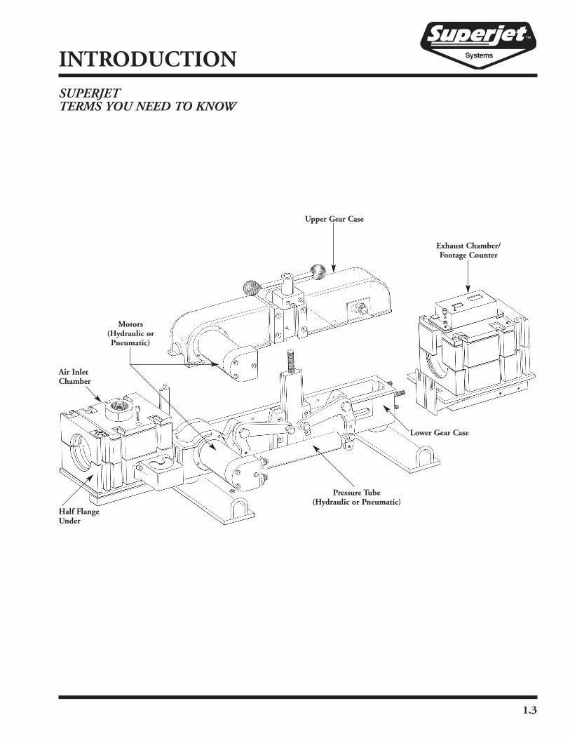
SUPERJETTERMS YOU NEED TO KNOW
1.3
INTRODUCTION
Air InletChamber
Half FlangeUnder
Pressure Tube(Hydraulic or Pneumatic)
Motors(Hydraulic orPneumatic)
Upper Gear Case
Exhaust Chamber/Footage Counter
Lower Gear Case

1.4
INTRODUCTION
IMPORTANT INFORMATION
It is very important to all of us at Sherman & Reillythat every machine is operated in a safe manner. Wehave taken every precaution to guard against the pos-sibility of an accident. To properly, safely operate thismachine, it is necessary and important that operatorsand service people read and understand the informa-tion in this and the engine manufacturer’s manual.ANYONE working around the machine shouldread the safety precautions in the manuals. Be awareeach warning and precaution is to help protect againstneedless injury. Taking unnecessary risks and ignoringwarnings is the primary cause of personal injury andfatal accidents in the work place. If you have any ques-tions regarding operation or safety of a procedure orsituation, contact the Sherman & Reilly CustomerService Manager at 1-800-251-7780.
This manual was prepared to help the operator useand service the machine in a safe manner. Responsi-bility for safety during operation and service rests withthe person(s) doing the work. Be alert, observe, andpractice all safety measures, including OSHA require-ments and ANSI standards, to help prevent the possi-bility of an accident.
This manual is of no value if the operator does notread and understand the instructions and precautions(before starting and trying to operate themachine). The operator must be awareof the capacities and limitations of themachine. It is the operator’sresponsibility to watch forsituations and conditionswhich could affect thenormal performance ofthe machine and safetyin the work area.
2.1
SAFETY
WARNING TERMS
Signal words in this manual call the operator’s atten-tion to safety concerns.
The word DANGER indicates the information relatesto a specific immediate hazard which, if disregarded,will result in severe personal injury or death.
The word WARNING indicates the informationrelates to a specific immediate hazard or unsafe prac-tice which, if disregarded, could result in personalinjury or death.
The word CAUTION indicates the information per-tains to a potential hazard or unsafe practice which, ifdisregarded, may result in minor personal injury orequipment damage.
The word NOTE indicates the information is impor-tant to the correct operation or maintenance of themachine.
2.2
SAFETY
2.2
OPERATOR SAFETY PRECAUTIONS
Do not place any part of the body into a potentialpinch point. The machine must be turned off andlocked out in accordance with OSHA regulationsbefore attempting to correct a problem, working on themachine, or performing regularly scheduled service.
� Do not attempt to operate Sherman & Reillyequipment without proper instruction, includingreading and understanding the manual.
� Obey and enforce all warnings including OSHArequirements and ANSI standards.
� Always wear proper safety equip-ment as required by employer.A respirator or particle mask isalso recommended.
� Never bypass safety switches or operateequipment with faulty safety devices.
� Be sure all guards and access covers are secure inplace when the machine is being operated.
� Be aware of people in the work area who may be atrisk during operation.
� Know all emergency shutdown procedures.
� Refer to the engine manufacturer’s manual for allinformation regarding the safe operation of theengine, including starting, operation and service.
� Be sure all air and hydraulic hoses and fittings aresecure.
� Safety clip or wire air fittings after connected.
� Ensure communications are working at all stationsand that start and stop signals are understood.
� Always warn downstream personnel when air is tobe sent through the system.
� Stay clear of exit end of duct when under pressure.
� Keep hands clear of hydraulic pusher while operat-ing.
� Never operate equipment while under the influ-ence of any substance which could impair operatorability or judgement. This presents a safety hazardin the work place.
� Do not operate equipment if work ability isimpaired by fatigue, illness, or other causes.
� Avoid contact with power unit engine andhydraulic fittings during operation and after use,until the unit has had time to cool.
� Do not refuel unit while the engine is running.
� Cable Route Construction• Use quality pre-lubricated duct with a duct tocable ratio of 2:1 if possible.
� • Do not kink or overstress duct during installa-tion.
� • Use only air tight couplers such as S&R DC-10couplers at duct splice points.
� • Plug ends of duct to keep water, mud and otherdebris out.
� • Remove plugs immediately prior to installation.
� Equipment Settings for Maximum Efficiency� • Air compressor sized to fit installation parameters
(185 CFMminimum, 750 CFMmaximum) 375CFM average requirement for 11⁄4" ID duct.
� • Air pressure at compressor (110 to 175 PSI).� • Air pressure at Superjet (100 to 175 PSI).
� Keep all body parts, head, and limbs away from allmoving parts.
� Know location and function of all controls, gauges,instruments, and protective devices.
� Never use controls or hoses for hand holds.
� Do not exceed unit specifications andlimitations for weight.
� Know where to get help in theevent of an emergency or injury.

3.1
OPERATIONSET-UP OF INSERTS

3.2
OPERATIONHYDRAULIC SUPERJET SET-UP
� Measure the duct. Select proper size duct clampand secure with screw. Use a duct clamp that isequal to or smaller than the duct to insure a goodmechanical connection.
Do not tape around duct in the duct clamp area.
� Select proper duct sealing insert. Make sure thelower one has the groove for the small rubber gas-ket and secure with proper screw in lower half of airinlet chamber. If duct diameter is in between ductsealing inserts, use the next larger size and applytape just to the end of the duct for a snug fit. Installthe large round rubber gasket and trim with sharpknife.
Duct Clamp should be smaller than the outsidediameter of the duct.
Duct Sealing Insert should be larger than the out-side diameter of the duct.
DUCT SEALING INSERTSMetric Inch25 0.9832 1.2634 1.3437 1.4640 1.5742 1.6548 1.8950 1.9560 2.3663 2.48
COMPRESSOR SIZESDuct Size (I.D.) Compressor.625" to 1.00" 185 CFM1.00" to 1.25" 250 CFM1.25" to 1.50" 375 CFM1.50" to 2.00" 450 CFM
2.00" 600 to 700 CFM
DUCT CLAMPSMetric Inch25 0.9832 1.2634 1.3437 1.4640 1.5742 1.6548 1.8950 1.9560 2.3663 2.48
DuctClamp
Screw
DuctSealingInsert
LargeRoundRubberGasket

3.3
OPERATION
� Measure the diameter of the cable. Install correctsize threaded cable end cap by screwing it on theend of the cable. Sometimes it is necessary to trima little of the cover at the end of the cable.
� Select proper size cable sealing insert and securewith screw in lower half of air inlet chamber. Use acable sealing insert that is just larger than the cableto insure the cable slides free.
� Install two correct size half round seals. Careshould be taken that the open “V” should be facingthe direction of air flow open to the duct side. Usea cable seal that is just larger than the cable toinsure the cable slides free.
� Place small round rubber gasket in the groove inthe cable sealing insert and along the sides of thebottom section of the air inlet chamber and intothe duct sealing insert.
Cable Sealing Inserts should be larger than the outsidediameter of the cable. It may be necessary to go to thenext larger size seal or insert in cases of borderlinecable or insert diameters
Cable Seals should be larger than the outside diameterof the cable (usually within 1mm). It may be necessaryto go to the next larger size seal or insert in cases of bor-derline cable or insert diameters.
CABLE SEALSMetric Inch Insert#10 .36 to .39 9 to 11#12 .40 to .47 11 to 12.5#14 .48 to .55 12.5 to 14#15 .56 to .59 14 to 15.5#16 .60 to .62 15.5 to 18#18 .63 to .70 17.5 to 22#19 .71 to .74 15.5 to 18#20 .75 to .76 17.5 to 22#22 .79 to .86 17.5 to 22#23 .87 to .90 22 to 24#25 .91 to .98 24 to 28#28 .99 to 1.10 24 to 28#30 1.11 to 1.18 28 to 32#32 1.19 to 1.25 28 to 32#35 1.26 to 1.37 32 to 36#38 1.38 to 1.49 32 to 36
CABLE END CAPSReorder Number
CEC-41CEC-49CEC-54CEC-60CEC-67CEC-74CEC-88CEC-92CEC-101
CABLE SEALING INSERTSMetric Inch6 to 9 .24 to .359 to 11 .35 to .43
11 to 12.5 .43 to .4912.5 to 14 .49 to .5514 to 15.5 .55 to .6115.5 to 18 .61 to .7117.5 to 22 .69 to .8722 to 24 .87 to .9424 to 28 .94 to 1.10
28 to 32 1.10 to 1.2532 to 36 1.25 to 1.41
ThreadedCableEnd Cap
HalfRoundSeal
CableSealingInsert
Groove
RoundRubberGasket
Air InletChamber

3.4
OPERATION
� Repeat seal installation procedure for the upperportion of the air inlet chamber. The upper ductsealing and cable sealing inserts do not have thesmall rubber gasket grooves.
� Insert lower guide for the counter in the lower por-tion of the exhaust chamber. Secure in place withlocking screws.
� Lubricate the duct. Pour Cablejet Lube in the endof the duct (see chart for quantities), then insertJetCoat Spreader “foam plug” (see chart for sizes).
� Secure the duct in the duct clamp with the end ofthe duct firmly seated in the duct sealing insert.Insert the white or green dummy cable plug incable groove.
Duct Qty. perI.D. 1000 ft.1 inch 3 fl. oz.
1.25 inch 4 fl. oz.1.5 inch 5 fl. oz.2 inch 6 fl. oz.
Reorder Duct I.D.Number to Fit
JCS-10-100 .75" to 1.125"JCS-10-125 1.25" to 1.50"JCS-10-150 1.50" to 2.00"
LowerGuide

3.5
OPERATION
The wire grip “catch” must be installed over the exitof the duct before pressurizing the system.
� Place top half of duct clamp and secure with bolts.Place top half of air inlet chamber and secure withbolts. Connect compressor air hose being sure toinsert both safety pins.
� Make sure air inlet valve is in closed position (hor-izontal). Start compressor. Open compressor airvalve. Wait for pressure to build to 100 psi mini-mum at the Superjet. Then open air inlet valve.This will advance foam plug at approximately 100feet per second in the duct. Be sure foam plug isout of duct before proceeding.
� After advancing the plug to the end of the ductrun, be sure to turn off the air valve on the com-pressor as well as the Superjet. In some instances itmay be necessary to shut the compressor off as well.Now, slowly open the valve at the Superjet to“bleed off” the air in the line, then return the valveat the Superjet to the “off position” before recharg-ing the line. The air valve handle on the compres-sor should be perpendicular to the valve in order toshut the valve off.
� Take top off of air inlet chamber. Remove dummycable plug. Insert cable guides in grooves of air inletchamber. Insert cable. Advance cable by hand intoduct 5 feet. Replace top of air inlet chamber.

3.6
OPERATION
� Be sure cable is resting in caterpillar tracks and thatit is centered in the cable guide opening. If not,adjust air inlet chamber by loosening the three nutsand center the air inlet chamber.
Pneumatic Superjet operators skip to page 3.13 forfinal set-up and operating instructions.
See page 4.3 for Superjet service requirements.
� Place the top of the cable pusher and tighten all theway until handle will not tighten anymore.
� Install the counter distance/speed indicator andtighten the four bolts. Reset the counter. Hold inplace until it shows zero.
� Connect the remote kill switch (when applicable)to the hydraulic power pack. Connect hydraulichoses from Superjet to hydraulic source usingquick disconnect couplings.

3.7
OPERATION
Do not exceed 800 PSI hydraulic pressure when jet-ting small dielectric cables under .60 inches O.D.There are some applications for cables under .50inches, do not exceed 500 PSI or use a Cablejet. Usea maximum of 1200 PSI when jetting larger, morerigid armored cables.
� Close hydraulic flow control handle (vertical posi-tion). “Back off” hydraulic pressure control (fullcounter clockwise position).
� Start engine. Engine should run at maximumRPM. Adjust the throttle control if necessary.Advance hydraulic pressure to pre-determined set-ting by rotating pressure control in the clockwisedirection. 800 PSI is recommended for dielectriccables under .6" diameter. Maximum of 1200 PSIfor larger and more rigid cables.
� Without air pressure, slowly advance the hydraulicflow control counter clockwise toward the horizon-tal position. At this point air compressor should berunning with the indicated pressure at the SUPER-JET at least 100 psi.

3.8
OPERATION
� Watching the distance indicator, at 150 feet startair flow by rotating the air inlet valve at theSuperjet to the vertical position.
� At intermediate position, all of the above steps areto be accomplished as outlined. The only differencewill be that the exhaust manifold will be fitted withthe proper size duct clamp in both bottom and top(See page 3.19 for cascading units).
� Duct sealing insert is secured in place in both thelower and upper sections. It is not necessary toplace the round rubber gasket in the exhaust man-ifold. Place the duct in the clamp and properly seatit in the duct sealing insert. Tighten the bolts onthe duct clamp.
� Place the exhaust module and tighten the bolts.The top of the pusher is left off until after the cablearrives.
DuctSealingInsert
ExhaustModule
3.9
OPERATION
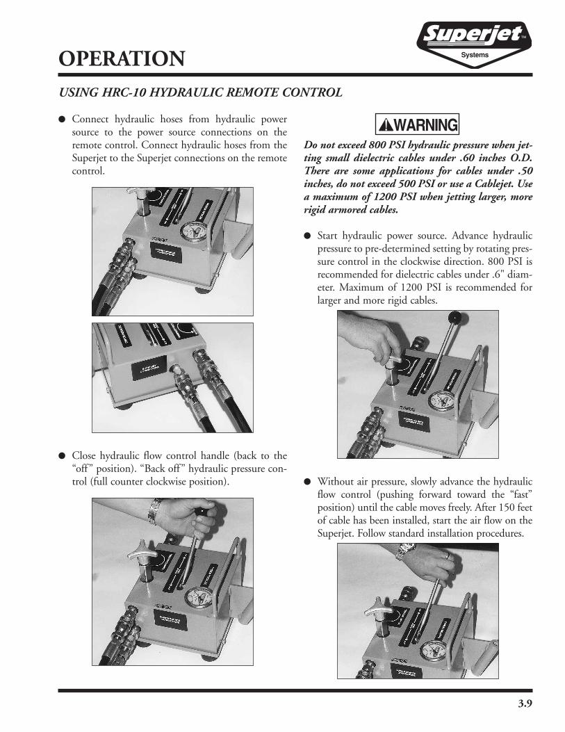
� Connect hydraulic hoses from hydraulic powersource to the power source connections on theremote control. Connect hydraulic hoses from theSuperjet to the Superjet connections on the remotecontrol.
� Close hydraulic flow control handle (back to the“off” position). “Back off” hydraulic pressure con-trol (full counter clockwise position).
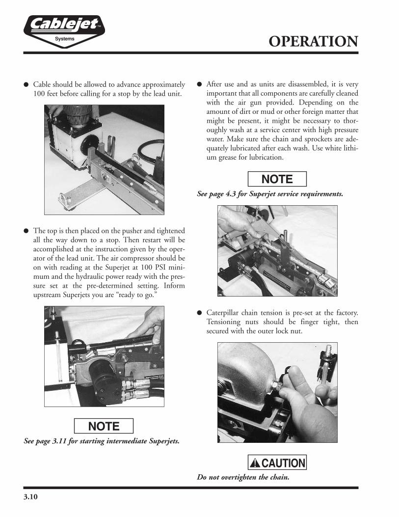
Do not exceed 800 PSI hydraulic pressure when jet-ting small dielectric cables under .60 inches O.D.There are some applications for cables under .50inches, do not exceed 500 PSI or use a Cablejet. Usea maximum of 1200 PSI when jetting larger, morerigid armored cables.
� Start hydraulic power source. Advance hydraulicpressure to pre-determined setting by rotating pres-sure control in the clockwise direction. 800 PSI isrecommended for dielectric cables under .6" diam-eter. Maximum of 1200 PSI is recommended forlarger and more rigid cables.
� Without air pressure, slowly advance the hydraulicflow control (pushing forward toward the “fast”position) until the cable moves freely. After 150 feetof cable has been installed, start the air flow on theSuperjet. Follow standard installation procedures.
USING HRC-10 HYDRAULIC REMOTE CONTROL
3.10
OPERATION
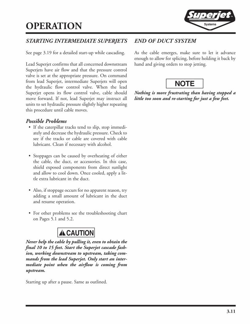
� Cable should be allowed to advance approximately100 feet before calling for a stop by the lead unit.
� The top is then placed on the pusher and tightenedall the way down to a stop. Then restart will beaccomplished at the instruction given by the oper-ator of the lead unit. The air compressor should beon with reading at the Superjet at 100 PSI mini-mum and the hydraulic power ready with the pres-sure set at the pre-determined setting. Informupstream Superjets you are “ready to go.”
See page 3.11 for starting intermediate Superjets.
� After use and as units are disassembled, it is veryimportant that all components are carefully cleanedwith the air gun provided. Depending on theamount of dirt or mud or other foreign matter thatmight be present, it might be necessary to thor-oughly wash at a service center with high pressurewater. Make sure the chain and sprockets are ade-quately lubricated after each wash. Use white lithi-um grease for lubrication.
See page 4.3 for Superjet service requirements.
� Caterpillar chain tension is pre-set at the factory.Tensioning nuts should be finger tight, thensecured with the outer lock nut.
Do not overtighten the chain.
3.11
OPERATIONSTARTING INTERMEDIATE SUPERJETS
See page 3.19 for a detailed start-up while cascading.
Lead Superjet confirms that all concerned downstreamSuperjets have air flow and that the pressure controlvalve is set at the appropriate pressure. On commandfrom lead Superjet, intermediate Superjets will openthe hydraulic flow control valve. When the leadSuperjet opens its flow control valve, cable shouldmove forward. If not, lead Superjet may instruct allunits to set hydraulic pressure slightly higher repeatingthis procedure until cable moves.
Possible Problems• If the caterpillar tracks tend to slip, stop immedi-ately and decrease the hydraulic pressure. Check tosee if the tracks or cable are covered with cablelubricant. Clean if necessary with alcohol.
• Stoppages can be caused by overheating of eitherthe cable, the duct, or accessories. In this case,shield exposed components from direct sunlightand allow to cool down. Once cooled, apply a lit-tle extra lubricant in the duct.
• Also, if stoppage occurs for no apparent reason, tryadding a small amount of lubricant in the ductand resume operation.
• For other problems see the troubleshooting charton Pages 5.1 and 5.2.
Never help the cable by pulling it, even to obtain thefinal 10 to 15 feet. Start the Superjet cascade fash-ion, working downstream to upstream, taking com-mands from the lead Superjet. Only start an inter-mediate point when the airflow is coming fromupstream.
Starting up after a pause. Same as outlined.
END OF DUCT SYSTEM
As the cable emerges, make sure to let it advanceenough to allow for splicing, before holding it back byhand and giving orders to stop jetting.
Nothing is more frustrating than having stopped alittle too soon and re-starting for just a few feet.
3.12
OPERATIONSLACK COIL LOCATIONS
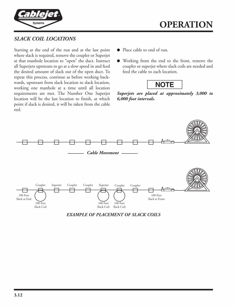
Starting at the end of the run and at the last pointwhere slack is required, remove the coupler or Superjetat that manhole location to “open” the duct. Instructall Superjets upstream to go at a slow speed in and feedthe desired amount of slack out of the open duct. Torepeat this process, continue as before working back-wards, upstream from slack location to slack location,working one manhole at a time until all locationrequirements are met. The Number One Superjetlocation will be the last location to finish, at whichpoint if slack is desired, it will be taken from the cablereel.
� Place cable to end of run.
� Working from the end to the front, remove thecoupler or superjet where slack coils are needed andfeed the cable to each location.
Superjets are placed at approximately 3,000 to6,000 foot intervals.
EXAMPLE OF PLACEMENT OF SLACK COILS
3.13
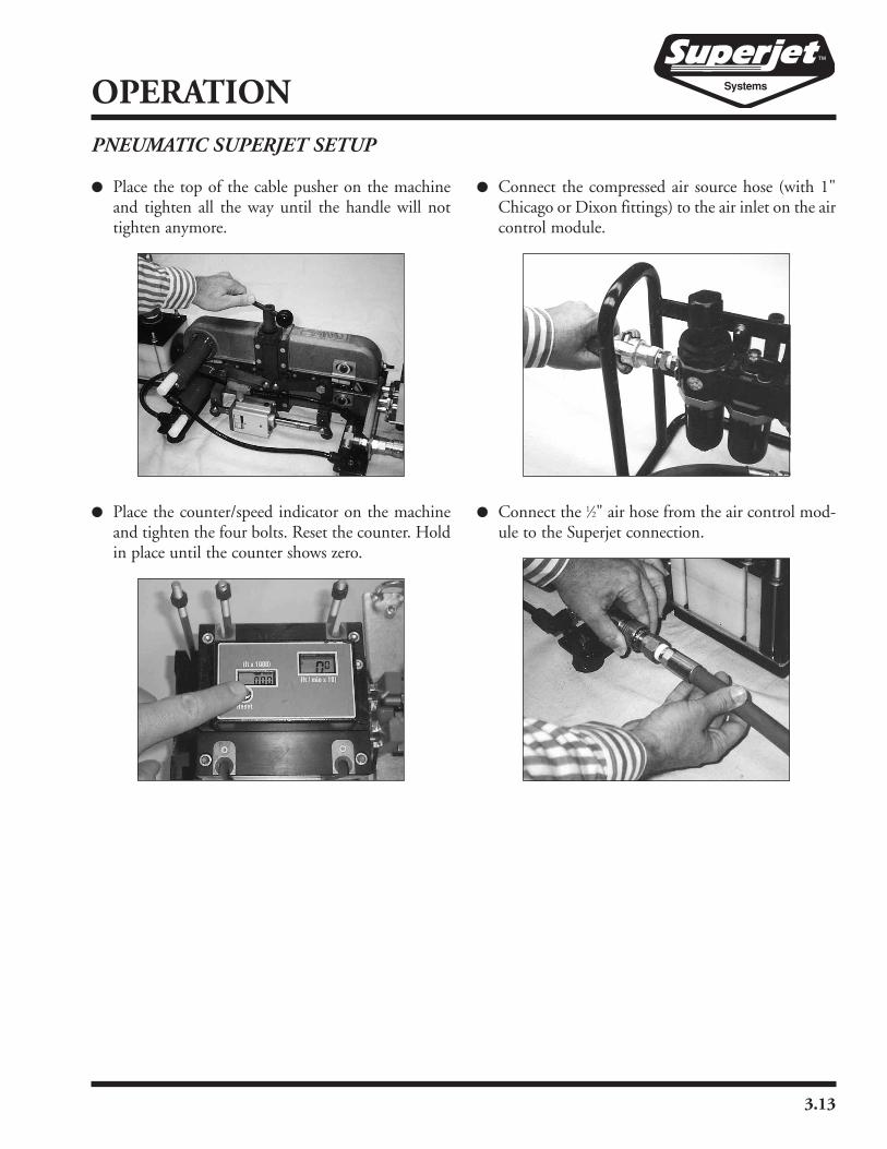
OPERATIONPNEUMATIC SUPERJET SETUP
� Place the top of the cable pusher on the machineand tighten all the way until the handle will nottighten anymore.
� Place the counter/speed indicator on the machineand tighten the four bolts. Reset the counter. Holdin place until the counter shows zero.
� Connect the compressed air source hose (with 1"Chicago or Dixon fittings) to the air inlet on the aircontrol module.
� Connect the 1⁄2" air hose from the air control mod-ule to the Superjet connection.
3.14
OPERATION
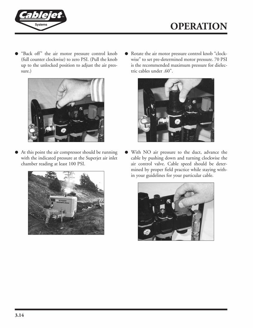
� “Back off” the air motor pressure control knob(full counter clockwise) to zero PSI. (Pull the knobup to the unlocked position to adjust the air pres-sure.)
� At this point the air compressor should be runningwith the indicated pressure at the Superjet air inletchamber reading at least 100 PSI.
� Rotate the air motor pressure control knob “clock-wise” to set pre-determined motor pressure. 70 PSIis the recommended maximum pressure for dielec-tric cables under .60".
� With NO air pressure to the duct, advance thecable by pushing down and turning clockwise theair control valve. Cable speed should be deter-mined by proper field practice while staying with-in your guidelines for your particular cable.
3.15
OPERATION
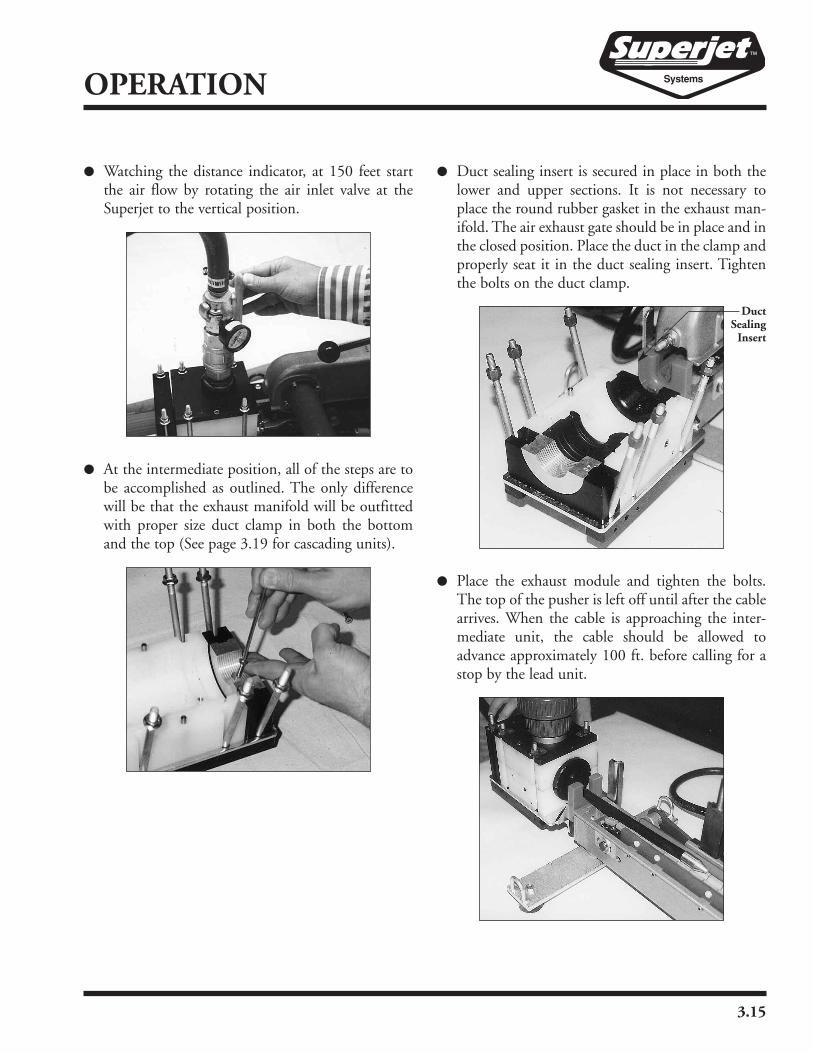
� Watching the distance indicator, at 150 feet startthe air flow by rotating the air inlet valve at theSuperjet to the vertical position.
� At the intermediate position, all of the steps are tobe accomplished as outlined. The only differencewill be that the exhaust manifold will be outfittedwith proper size duct clamp in both the bottomand the top (See page 3.19 for cascading units).
� Duct sealing insert is secured in place in both thelower and upper sections. It is not necessary toplace the round rubber gasket in the exhaust man-ifold. The air exhaust gate should be in place and inthe closed position. Place the duct in the clamp andproperly seat it in the duct sealing insert. Tightenthe bolts on the duct clamp.
� Place the exhaust module and tighten the bolts.The top of the pusher is left off until after the cablearrives. When the cable is approaching the inter-mediate unit, the cable should be allowed toadvance approximately 100 ft. before calling for astop by the lead unit.
DuctSealingInsert

3.16
OPERATION
� The top is then placed on the pusher and tightenedall the way down to a stop. Then restart will beaccomplished, as outlined, at the instruction givenby the operator of the lead unit. Air compressorshould be on with the air control valve open, withreading at the Superjet at 100 PSI minimum andthe air motor pressure setting at the pre-deter-mined setting. Inform upstream Superjets that youare “ready to go.”
� When operating the unit, (on older models) checkthe water separator for condensation. If necessary,“bleed off” the excess water by turning the valve onthe bottom of the reservoir counter-clockwise.When unit is stopped and there is NO air pressureon the system, remove the reservoir and empty.Reconnect the reservoir and continue.
Keep fingers clear of the air stream.
� While operating, check to be sure the drip feed onthe oil reservoir is set for 1 to 2 drops per minute.Increase or decrease by turning the clear lubricatorknob. The clear knob also acts as a drip viewer.
Be sure the reservoir never runs dry.
Use Texaco Regal Oil R&O 32 (premium grade) orconsult the operator’s manual for alternates.

3.17
OPERATIONSTARTING INTERMEDIATEPNEUMATIC SUPERJETS
See page 3.19 for a detailed start-up while cascading.
Lead Superjet confirms that all concerned downstreamSuperjets have air flow and that the air motor pressurecontrol valve is set at the appropriate pressure.Intermediate unit pressures should be 2 to 5 PSI belowthat of preceding units when “in-line”. On commandfrom lead Superjet, intermediate Superjets will openair motor control valve. When lead Superjet opens itsflow control valve, cable should move forward. If not,lead Superjet may instruct all units to set air motorpressure slightly higher, repeating this procedure untilcable moves.
Possible Problems• If the caterpillar tracks tend to slip, stop immedi-ately and decrease the air motor pressure. Check tosee if the tracks or cable are covered with cablelubricant. Clean if necessary with alcohol.
• Stoppages can be caused by overheating of eitherthe cable, the duct, or accessories. In this case,shield exposed components from direct sunlightand allow to cool down. Once cooled, apply a lit-tle extra lubricant in duct.
• Also, if stoppage occurs for no apparent reason, tryadding a small amount of lubricant in duct andresume operation.
• For other problems see the troubleshooting charton Pages 5.1 and 5.2.
Never help the cable by pulling it, even to obtain thefinal 10 to 15 feet. Start the Superjets cascade fash-ion, working downstream to upstream, taking com-mands from lead Superjet. Only start an interme-diate point when the airflow is coming fromupstream.
Starting up after a pause. Same as outlined.
END OF DUCT SYSTEM
As the cable emerges, make sure to let it advanceenough to allow for splicing, before holding it back byhand and giving orders to stop jetting.
Nothing is more frustrating than having stopped alittle too soon and re-starting for just a few feet.

3.18
OPERATION
� After use and as units are disassembled, it is veryimportant that all components are carefully cleanedwith the air gun provided. Depending on theamount of dirt or mud or other foreign matter thatmight be present, it might be necessary to thor-oughly wash at a service center with high pressurewater. Make sure the chain and sprockets are ade-quately lubricated after each wash. Use white lithi-um grease for lubrication.
Keep grease and cable lubricants off of the rubbertracks as they may cause the cable to slip in thetracks, especially at intermediate positions. Rub-bing alcohol (Isopropyl) may be used to wipe sili-cone based lubricants and grease off of the rubbertracks.
� Caterpillar chain tension is pre-set at the factory,however, if the chain ever needs to be adjusted, thetensioning nut should only be finger tight.
Do not overtighten the chain.
� Pneumatic Superjet Set-up. Superjet pneumaticcontrols may be operated on the ground, in a man-hole, or secured to the case with the mounting rodsupplied.

3.19
OPERATIONCASCADING
Cascading In Line Below GroundSet-up of Intermediate Positions
� Check duct integrity and lubricate prior to cablearrival at intermediate position.
� Connect exhaust module and flexible hose whennecessary.
� Wait for #1 control to inform you of cable locationas it approaches #2 location with top of pusherremoved, but unit in place.
� Guide cable through unit and into duct. Let go 30to 100 feet and ask for stop.
� Place top on unit and await order from #1 to start.
� Turn on air full, start power pack.
� Unit #1 will instruct what hydraulic pressure to set,follow instruction, and proceed.
� For all successive Superjets follow same procedure.
Cascading Above Ground with Duct Loop
� Set up intermediate unit(s) above ground behindmanhole or handhole.
� Bring upstream inner duct above ground and forma loop so duct can be installed in duct clamp andexhaust module at rear of unit.
� Bring downstream inner duct above ground andplace in front duct clamp as in regular set-up pro-cedure.
� Follow same operating procedure as Cascading inline.
When cascading above ground, it may be necessaryto make extension tubes of spare inner duct and anairtight coupler. After the installation, the extensiontube may be stripped off and slack cable exposed.
Duct
Air Hose
Power Pack
Superjet
DC-10
Duct
Air Hose
Power Pack
Superjet

3.20
OPERATION
Cascading Above Ground with Cable Loop
� Set up intermediate unit above ground behindmanhole or handhole.
� With this method, the duct clamps on the exhaustend of the Superjet are not needed and should beremoved.
� Bring upstream inner duct up to top of manholeaway from any obstructions, i.e. ladders, otherducts, cables, etc.
� Bring downstream inner duct up above ground andconnect to front duct clamp as in regular set-upprocedure.
� To operate:� (a) Each unit will now operate independent of each
other.� (b) When #1 unit feeds cable, intermediate units
will form a slack cable loop.
� Monitor the loop size and adjust individual speedaccordingly to increase or decrease the diameter ofthe slack loop. This method is ideal for use at “slackcoil locations.”
End of Installation
� When cable reaches the end point, do not stopuntil all slack has been taken.
� Stop cable by holding at inner duct end or stoppingSuperjets by command.
Cable
Air Hose
Power Pack
Superjet
DC-10
3.21
OPERATIONDC-10 COUPLER INSTALLATION
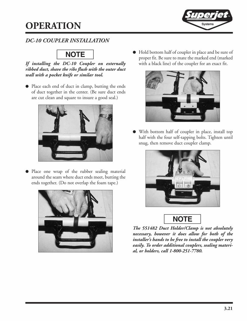
If installing the DC-10 Coupler on externallyribbed duct, shave the ribs flush with the outer ductwall with a pocket knife or similar tool.
� Place each end of duct in clamp, butting the endsof duct together in the center. (Be sure duct endsare cut clean and square to insure a good seal.)
� Place one wrap of the rubber sealing materialaround the seam where duct ends meet, butting theends together. (Do not overlap the foam tape.)
� Hold bottom half of coupler in place and be sure ofproper fit. Be sure to mate the marked end (markedwith a black line) of the coupler for an exact fit.
� With bottom half of coupler in place, install tophalf with the four self-tapping bolts. Tighten untilsnug, then remove duct coupler clamp.
The 551482 Duct Holder/Clamp is not absolutelynecessary, however it does allow for both of theinstaller’s hands to be free to install the coupler veryeasily. To order additional couplers, sealing materi-al, or holders, call 1-800-251-7780.

3.22
OPERATION

4.1
SERVICEGENERAL SERVICE
Close attention to proper preventive measures and ser-vice procedures will ensure and extend trouble-freeoperation of equipment. Proper lubrication and care-ful attention to the hydraulic system suction filter aretwo vital areas. The objective of scheduled serviceshould be to anticipate and prevent operational prob-lems before they require extended shutdown forrepairs.
IMPORTANT INFORMATION
The service guidelines outlined in this manual areeffective methods. These guidelines are not all inclu-sive. Anyone who performs service or repair on aSherman & Reilly machine must be completely sat-isfied that no one’s safety will be jeopardized andtake responsibility for these actions.
This manual will guide you in disassembling yourHydraulic or Pneumatic Superjet for repairs or routinemaintenance. If there are any questions about safety,procedure or precautions, contact Sherman & Reillyat 800-251-7780 before attempting to do the work.
Service should be scheduled to allowadequate time so the procedure canbe completed correctly. It must bedone by skilled, trained servicepersonnel with a good basicknowledge of equipment, pro-cedures, and safety practices.Accurate records should be keptof all service and repairs.
SUPERJET
CABLEJET

4.2
SERVICESAFETY PRECAUTIONS
� Make sure the machine is locked out in accordancewith OSHA requirements.
� Make sure that all precautions are taken to supportcomponents before loosening or removing bolts.
� When working on any hydraulic connection orpart:
� • Be sure there is no pressure on fluid at the loca-tion of the work.
� • Make sure nothing will move or drop when loos-ening a connection.
� • Collect all the hydraulic fluid which will drainfrom the loosened connection.
� • Use oil-dry or some absorbentmaterial to soak up any fluidspills to keep working surfacesfrom becoming slippery.
� • Cover all open connectionsto prevent loss and contam-ination to the hydraulicsystem.
TOOLS REQUIRED TO DISASSEMBLE/ASSEMBLE SUPERJET AND CABLEJET
• 13mm T-handle Allen Wrench• 17-22mm Open End Wrench• 10mm Open End Wrench• 4mm T-handle Allen Wrench• 5mm T-handle Allen Wrench• Needle Nose Pliers• Circle Clip Pliers• Small Hammer• Adjustable Wrench• Flathead Screw Driver• Phillipshead Screw Driver• White Lithium Grease
� Take all fire prevention safetymeasures before using a welderor cutting device, includinggrinders. Have a fully chargedfire extinguisher near thelocation of the work.
� Be sure everyone involved in the maintenance, ser-vice or repair process understands what is beingdone and all of the safety precautions which needto be taken during the procedure.
� Make sure all lifting devices, chains, slings, andhooks are in good condition and have the ratedcapacity to do the job. Use guide lines when neces-sary for control during the lifting process.
� Always wear proper protectiveclothing and equipment whenperforming service: gloves,safety glasses, etc.
4.2

4.3
SERVICESUPERJET SERVICE REQUIREMENTS
� • Keep the Superjet clean and well lubricated.
� • Replace any worn or broken parts with factoryoriginal parts as soon as they are detected.
DAILY SERVICE REQUIREMENTS
Follow daily service procedures when unit is in con-stant use.
� Hydraulic Superjet� • Thoroughly pressure wash (with soap) both
chains, inlet and exhaust chambers (excludingthe footage counter) after each use. Running theunit at a low speed will aid in cleaning thechains. Allow to dry.
� • Check for proper chain tension: 1⁄4" to 1⁄2" slack atthe center of the chains.
� • Grease the chains, slide pads and sprockets withwhite lithium grease. The grease can be spreadmore evenly if the unit is running at a low rate ofspeed.
� • Spray a light lubricant (WD-40) on the toptightening screw, the tension adjusting linkageand rod, and the top and bottom of the cham-bers tightening nuts and bolts.
� • Note the condition of the drive chains.� • Remove any dirt or debris from the quick cou-
plers.� • Check oil, fuel and hydraulic fluid levels in the
power pack. See operating instructions for powerpack maintenance.
� Pneumatic Superjet� • Thoroughly pressure wash (with soap) both
chains, inlet and exhaust chambers (excludingthe footage counter) after each use. Running theunit at a low speed will aid in cleaning thechains. Allow to dry.
� • Check for proper chain tension: 1⁄4" to 1⁄2" slack atthe center of the chains.
� • Grease the chains, slide pads and sprockets withwhite lithium grease. The grease can be spreadmore evenly if the unit is running at a low rate ofspeed.
� • Spray a light lubricant (WD-40) on the toptightening screw, the tension adjusting linkageand rod, and the top and bottom of the cham-bers tightening nuts and bolts.
� • Note the condition of the drive chains.� • Remove any dirt or debris from the quick cou-
plers.� • Check the air control module for water and
empty as necessary.� • Check the air control module lubricator reser-
voir oil level. Oil must be maintained in thereservoir at all times or serious damage will occurto the air motors if not oiled properly.
� • Check the drip feed for the oiler and make surethe motors are getting at least 1 to 2 drips perminute. If not, adjust as necessary. Air motorsare expensive!
� • Check the air motor mufflers. If the mufflers areclogged or dirty, poor performance can beexpected.
EVERY 100 HOURS OF SERVICEHydraulic and Pneumatic Superjet� • Repeat Daily service requirements.� • Loosen the chains, inspect the slide pads and
make sure the chain rollers turn freely. Replacepads and chain if necessary.
EVERY 500 HOURS OF SERVICEHydraulic and Pneumatic Superjet� • Repeat Daily and 100-Hour service require-
ments.� • Remove the chains, inspect, thoroughly clean,
and check that the idler sprocket turns freely.Replace any item showing accelerated wear.Grease and reassemble.

4.4
SERVICECABLEJET SERVICE REQUIREMENTS
� • Keep the Cablejet clean and well lubricated.
� • Replace any worn or broken parts with factoryoriginal parts as soon as they are detected.
DAILY SERVICE REQUIREMENTS
Follow daily service procedures when unit is in con-stant use.
� • Thoroughly pressure wash (with soap) both thetop and base of the Cablejet, especially the driveroller assembly in the base and the air inletchamber.
� • Check the condition of the drive washers andreplace as necessary. Worn out drive washerscause poor performance.
� • Grease the drive roller assembly thoroughly withwhite lithium grease.
� • Spray a light lubricant (WD-40) on the top andbottom of the chambers tightening nuts andbolts.
� • Check the water separator for water and emptyas necessary. On certain occasions during opera-tion, the water separator may need to be emptiedevery 15 to 20 minutes.
� • Check the motor lubricator reservoir oil level.Oil must be maintained in the reservoir at alltimes or serious damage will occur to the airmotor if not oiled properly.
� • Check the drip feed for the oiler and make surethe motors are getting at least 1 to 2 drips perminute. If not, adjust as necessary. Air motors forthe Cablejet are expensive!
EVERY 100 HOURS OF SERVICE� • Repeat Daily service requirements.� • Remove the air motor and the drive roller assem-
bly from both the top and base of the Cablejetand thoroughly clean with soap and water.
� • Check the condition of the drive washers andreplace as necessary. Worn out drive washerscause poor performance.
� • Check the condition of the drive roller assemblysprockets as well as the air motor sprocket.
� • Grease the drive roller assembly thoroughly withwhite lithium grease and reassemble.
EVERY 500 HOURS OF SERVICE� • Repeat Daily and 100-Hour service require-
ments.� • Remove the air hoses, air motor, and the drive
roller assembly, from both the top and base ofthe Cablejet and thoroughly clean with soap andwater.
� • Completely disassemble the four driver rollerassemblies and clean all parts.
The assembly is under a preload of about 22 lbs.
� • Check the condition of the drive washers andreplace as necessary. Worn out drive washerscause poor performance.
� • Check the condition of the drive roller assemblysprockets as well as the air motor sprocket.
� • Grease the drive roller assembly with white lithi-um grease.
� • When reassembling the drive roller assembly inthe top and base of the Cablejet, inspect thenylatron housing for excessive wear. If the driveroller assembly has a lot of play in the base ortop, it may be necessary to replace the nylatrontop or base or both.
4.5
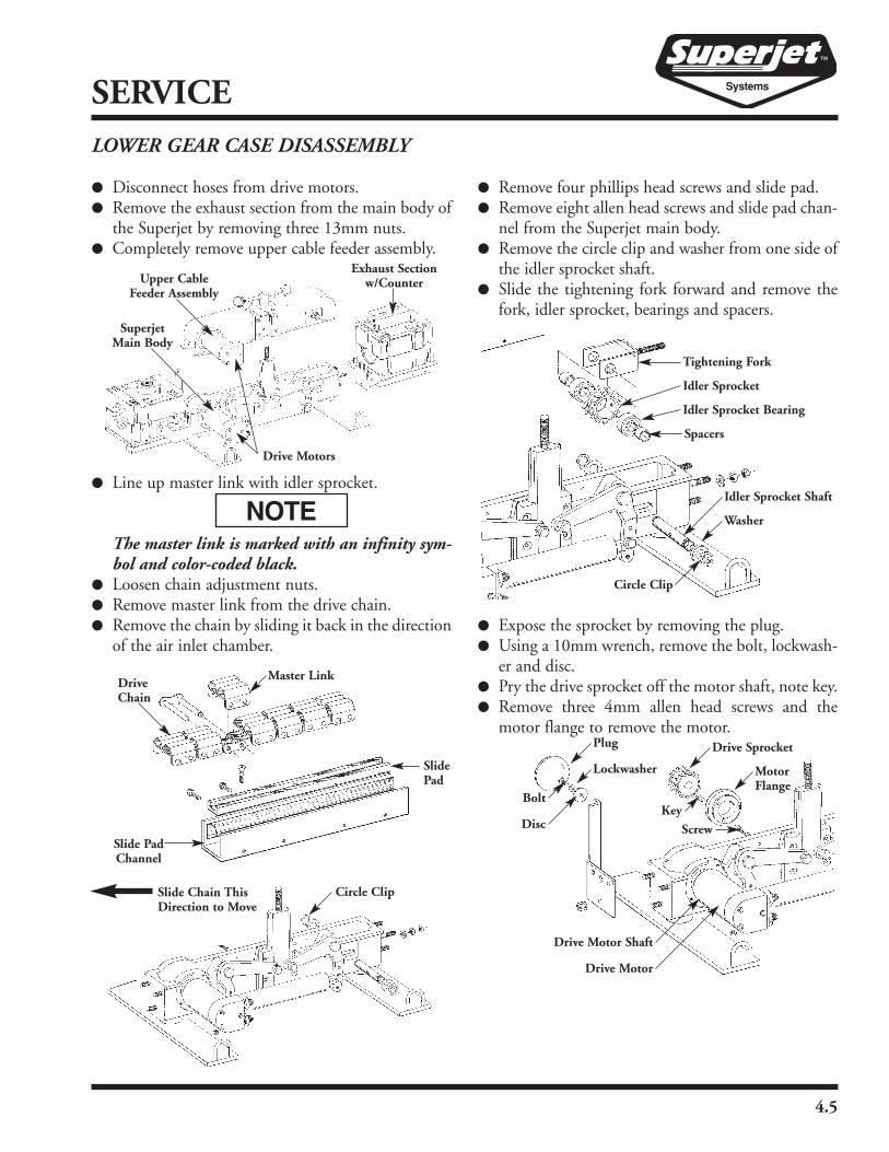
SERVICELOWER GEAR CASE DISASSEMBLY
� Disconnect hoses from drive motors.� Remove the exhaust section from the main body of
the Superjet by removing three 13mm nuts.� Completely remove upper cable feeder assembly.
� Line up master link with idler sprocket.
The master link is marked with an infinity sym-bol and color-coded black.
� Loosen chain adjustment nuts.� Remove master link from the drive chain.� Remove the chain by sliding it back in the direction
of the air inlet chamber.
� Remove four phillips head screws and slide pad.� Remove eight allen head screws and slide pad chan-
nel from the Superjet main body.� Remove the circle clip and washer from one side of
the idler sprocket shaft.� Slide the tightening fork forward and remove the
fork, idler sprocket, bearings and spacers.
� Expose the sprocket by removing the plug.� Using a 10mm wrench, remove the bolt, lockwash-
er and disc.� Pry the drive sprocket off the motor shaft, note key.� Remove three 4mm allen head screws and the
motor flange to remove the motor.
Exhaust Sectionw/Counter
Drive Motors
SuperjetMain Body
Upper CableFeeder Assembly
Master LinkDriveChain
SlidePad
Slide PadChannel
Tightening Fork
Idler Sprocket
Idler Sprocket Bearing
Spacers
Circle Clip
Idler Sprocket Shaft
Washer
Plug
Lockwasher
Disc
Bolt
Drive Motor
Drive Motor Shaft
Drive Sprocket
MotorFlange
Screw
Key
Circle ClipSlide Chain ThisDirection to Move

4.6
SERVICELOWER GEAR CASE ASSEMBLY
� Bolt the motor to the main body using three 4mmallen head screws and the motor flange.
� Place the key in the motor shaft and mount thedrive sprocket to the motor.
� Secure the sprocket with the disc, bolt and lockwasher.
� Insert the plug into the main body.
� Position the tightening fork in the main body.
� Put the idler sprocket bearings in the sprocket,position the sprocket and spacers inside the tight-ening fork.
� Insert the idler sprocket shaft through the bearingsand secure with washers and circle clips.
� Insert the slide pad channel into the main body,and belt in place with eight allen head screws.
� Put the slide pad inside the channel and secure withfour phillips head screws.
� Slide the drive chain in place in the slide pad.
� Connect the chain with the master link.
The master link is marked with an infinity symboland color-coded black.
� Install both chain adjustment nuts on the tighten-ing fork threaded rod.
� Tension the chain by rotating the chain manually asyou tighten the chain tightening fork with the nutuntil the chain will not move. Loosen the nut 11⁄4revolutions. This will give you the proper chaintension on the upper gear case.
Overtightening the chain will cause excessive pre-mature wear. Leaving the chain too loose maycause the chain to bind or lock up.
Plug
Lockwasher
Disc
Bolt
Drive Motor
Drive Motor Shaft
Drive Sprocket
MotorFlange
Screw
Key
Tightening Fork
Idler Sprocket
Idler Sprocket Bearing
Spacers
Circle Clip
Idler Sprocket Shaft
Washer
Master LinkDriveChain
SlidePad
Slide PadChannel
Circle ClipSlide Chain ThisDirection to Move

4.7
SERVICE
� Install the upper cable feed assembly.
� Attach the exhaust section to the main body withthree 13mm nuts.
� Connect drive motor hoses.
CHAIN ASSEMBLY
� Position the chain so the connector can be startedin the two end links.
� Insert and align spacer links. The center spacer linkwill be one thick spacer or two thin spacers; theoutside spacer link will always be one thin spacer.
� Push connector through the center spacer link(s).Continue pushing connector until you are able toattach the outside spacer link to the connector.Both chain ends should be connected with connec-tor and spacer links in place.
� Align master link over the assembled connector.Push the master link down on the connector. Thiswill require some effort to get the master link tosnap over and hold the connector. Make sure theoutside spacer link is captured and held into placeby the master link. The two pins on the connectorshould be aligned with the holes on the master linkon both sides of the chain.
The master link is marked with an infinity sym-bol and color-coded black.
Exhaust Sectionw/Counter
Drive Motors
SuperjetMain Body
Upper CableFeeder Assembly
Master LinkConnector
Center Spacer Link
Outside Spacer Link

4.8
SERVICEUPPER CABLE FEEDER DISASSEMBLY
� Disconnect drive motor hoses.
� Line up the master link with the idler sprocket.
The master link is marked with an infinity sym-bol and color-coded black.
� Loosen and remove chain adjustment nuts andwasher.
� Remove the master link from the drive chain.
� Slide the drive chain back and remove.
� Remove four phillips head screws and the upperslide pad.
� Remove the 5mm allen head screw and the slidepad pivot bushing, allowing the slide pad pivot tobe removed.
� Remove the circle clip and washer from one side ofthe idler sprocket shaft.
� Slide the tightening fork forward and remove thefork, idler sprocket bearings and spacers.
� Remove the plug to expose the sprocket.
� Use a 10mm wrench to remove the bolt, lockwash-er and disc.
� Pry the drive sprocket from the motor shaft notekey.
� Remove three 4mm allen head screws and motorflange to remove the motor.
Slide Pad Pivot
5mm Allenhead
Pivot Bushing
Slide Pad
FrameUpper Cable Feeder
Master Link
Drive Chain
Upper Cable Feeder Cable Adjustment Nuts
Idler Sprocket
Idler Sprocket Bearing
Spacer
IdlerSprocket
Shaft
Washer
CircleClip
Tightening
Plug
Lockwasher
Disc
Bolt
Drive Motor
AllenheadScrew
MotorFlange
Key
DriveSprocket
Upper Cable Feeder
4.9
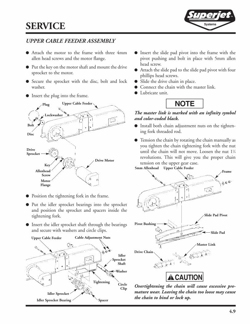
SERVICEUPPER CABLE FEEDER ASSEMBLY
� Attach the motor to the frame with three 4mmallen head screws and the motor flange.
� Put the key on the motor shaft and mount the drivesprocket to the motor.
� Secure the sprocket with the disc, bolt and lockwasher.
� Insert the plug into the frame.
� Position the tightening fork in the frame.
� Put the idler sprocket bearings into the sprocketand position the sprocket and spacers inside thetightening fork.
� Insert the idler sprocket shaft through the bearingsand secure with washers and circle clips.
� Insert the slide pad pivot into the frame with thepivot pushing and bolt in place with 5mm allenhead screw.
� Attach the slide pad to the slide pad pivot with fourphillips head screws.
� Slide the drive chain in place.� Connect the chain with the master link.� Lubricate unit.
The master link is marked with an infinity symboland color-coded black.
� Install both chain adjustment nuts on the tighten-ing fork threaded rod.
� Tension the chain by rotating the chain manually asyou tighten the chain tightening fork with the nutuntil the chain will not move. Loosen the nut 11⁄4revolutions. This will give you the proper chaintension on the upper gear case.
Overtightening the chain will cause excessive pre-mature wear. Leaving the chain too loose may causethe chain to bind or lock up.
Plug
Lockwasher
Disc
Bolt
Drive Motor
AllenheadScrew
MotorFlange
Key
DriveSprocket
Upper Cable Feeder
Upper Cable Feeder Cable Adjustment Nuts
Idler Sprocket
Idler Sprocket Bearing Spacer
IdlerSprocket
Shaft
Washer
CircleClip
Tightening
Slide Pad Pivot
5mm Allenhead
Pivot Bushing
Slide Pad
FrameUpper Cable Feeder
Master Link
Drive Chain

4.10
SERVICECABLEJET DISASSEMBLY
� Remove air inlet and exhaust chamber upperhalves.
� Remove all air lines by pressing in on blue lockingrings and pulling the hose out of the fitting.
� Remove hex screws, pillow cover and motor fromthe frame under. With hex screws removed, pullmotor. It may require some force to unseat theassembly.
� Remove the cover.
� Gently pry the drive roller assemblies away fromthe “frame upper” and “frame under”.
� Clean all components thoroughly.
� Remove the circle clip from the gear end of thedrive roller assembly.
The drive roller assembly is under a spring load.
� Use the gear puller to remove the gear wheel fromthe drive shaft.
� Inspect the drive roller assembly and replace wornparts as necessary.
� Remove three T-10 torx head screws to remove thedrive washer from the brass drive roller.
� Check drive washers for excessive wear. Check shaftand brass driving roller for wear, movement orloose fit.
Air Inlet Chamber
Exhaust Chamber
Base Plate
Pillow Cover
Pneumatic Motor
Frame Under
HexScrew
Cover
O-Ring
Frame UpperO-Ring
Cover
HexScrew
Drive Roller Assembly

4.11
SERVICE
� Check bearings for wear and movement.
� Check all gear wheels for tooth wear. The wheelshould move with very little play.
When reassembling the drive roller assembly, useholding clamps to contain the parts and compres-sion springs while inserting circle clips.
Check for movement when inserting the drive rollerassembly into the frame upper/frame under. If thefit is loose the Nylatron Frame may need to bereplaced.
DRIVE MOTOR DISASSEMBLY
� Remove the sock-screw, spring washerand washer from motor shaft end.
� Use gear puller to remove gear wheelfrom motor shaft (note key).
� Unscrew the motor from the pillowcover.
Circle Clip
Washer
Socket, Green
Brass Driving Roller
Brass Driving Roller
Oil Seal
Socket, Green
Washer Circle Clip
Washer
Leaning Socket
Compression Spring
Driving Washer
Drive Shaft
Driving Washer
Compression Spring
Gear Wheel
Bearing
Sock-screw
Spring Washer
Washer
Gear Wheel
Key
Washer
Hex Screw
Pillow Cover
Pneumatic Motor
Pivot
Sock-screw
Spring Pin

4.12
SERVICEDRIVE MOTOR ASSEMBLY
� Screw the motor into the pillow cover.
� Insert key on motor shaft and install gear wheel.
� Position washer, spring washer and secure the gearwheel to the motor shaft with sock-screw.
When reassembling the drive motor assembly andframe under, take care to line up teeth on the gearwheel to prevent damage to the unit when the boltsare tightened.
� Check the water separator filter and wash or replaceit as necessary. Make sure the o-ring is on top of thereservoir during reassembly.
Pillow Cover
Pneumatic Motor
Frame Under
HexScrew
Check
Filter
O-Ring
Reservoir

4.13
SERVICECOUNTER REMOVAL� The Footage Counter
and Speed Indicatorcounters are locateddirectly behind the rec-tangular cover on theindicator. Use the3mm allen wrenchprovided with the stan-dard tool package toremove the two sockethead cap screws on thecorners of the cover.
� The counters are nowexposed.
BATTERY REPLACEMENT(Meter batteries — Use Eveready E-CR2032, 3 voltlithium or equal)
� In order to expose the battery, the socket on theback of the countersmust be removed bysliding them up-ward.
� Remove the cover onthe back of the counterby inserting a coin andturning counterclock-wise.
� Remove the old batteryand insert a new onewith the positive (+)pole facing upward.
� Replace the cover.
BATTERY REPLACEMENT(Transmitter battery — Use Energizer A23 or anyequal alkaline 12 volt battery)
� Remove the fourscrews from the bot-tom of the footagecounter using the TorxDriver provided withthe standard tool pack-age.
� Remove the cover byturning a flat headscrew driver counter-clockwise.
� Remove the old batteryand insert a new onewith the positive (+)pole facing outward.
� Replace the cover withthe four screws.
RESETTING THE METERS� Push the AC button on
the back of the meterto clear and reset thecomputer. The ODOdisplay will appearwith a zero (0) figure.
� Press and hold the redbutton until a fourdigit number appearswith the last numberflashing.
� Press the yellow button to increase and decrease theflashing number and the red button to change theposition.
Distance Counter in feet (left) 0526Speed Counter in feet (right) 0876
Distance Counter in meters (left) 1596Speed Counter in meters (right) 1596
� Press the red button several times until returning to

4.14
SERVICEa screen with only (1) zero and the letters ODO inthe bottom left corner.
� Press the yellow button (4) times. The letters DSTshould appear in the bottom left corner.
INDICATOR REASSEMBLY
� Reverse the steps fol-lowed in sections 1 and2.
� Be sure to place thetwo washers under thecover plate.
TESTING THE DISTANCE COUNTER
� In order to test the distance counter for accuracy aftersetting, put a mark on the counter wheel and rotate it20 times. The distanceshould increase by tenfeet (20 rotations equalsten feet). If the distancedoes not increase by tenfeet after 20 or 21 revo-lutions of the wheel, goback and reset the counter and check the setting val-ues.
RESETTINGDISTANCEINDICATOR
� Press and hold down thered button on the top ofthe outside cover.
If the counter stands idle on a job, the display willblank out. The footage number is in memory and willshow up again when the counter is used the next time.

5.1
TROUBLESHOOTINGPROBLEM POSSIBLE CAUSE(S) REMEDY
No Cable Movement • Obstruction in duct • Remove obstruction and repair duct asnecessary.
• Cable in bind in Superjet • Remove cover, realign cable, install cover.
• Duct needs lubricating • Add proper amount of lubricant to ductand re-start.
• Air leakage in duct causing • Check duct splice points (couplers)loss of energy in system • and repair as necessary.
Slow Cable Movement • Overheating of cable, (due to • Shield cable reel from direct sunlightexposure), duct or equipment • Allow duct or equipment to cool,
• lubricate and resume.
• Low air inlet pressure • Increase compressor pressure or getshould be 100 PSI minimum • another compressor.
Caterpillar Tracks Slip • Overdriving the system • Decrease the hydraulic or pneumaticmotor pressure.
• Lubricant on tracks • Remove with rag, use proper amount oflubricant.
• Tracks are loose • Tighten adjusting nuts on track mecha-nism. Chain should be firm and fingertight but not overtight.
• Too low of compression setting • Adjust cylinder to higher setting.Hydraulic Superjet only.
Air Leakage at Air • Improper size duct sealing insert • Check diameter of duct for proper ductInlet Chamber • sealing insert size. See chart inside of
Superjet case or in manual and installproper size.
• Duct is in between duct sealing • If duct is slightly smaller than closest• insert sizes • insert size, place a few wraps of vinyl tape
around duct for proper seal.
• Sealing materials not properly • Check rubber cord in air inlet chamber.installed, or worn • Check rubber cord at duct sealing inserts.
Be sure ends are cut flush.• Check that cable seals are in place.• Replace cords and seals when necessary.
• No cable or dummy cable plug • Insert cable thru Superjet and into plugsealing air inlet chamber • duct, or use dummy cable plug to seal
chamber.
5.2
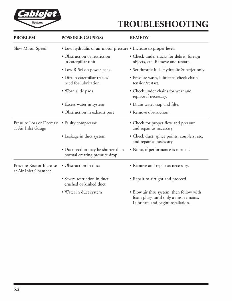
TROUBLESHOOTINGPROBLEM POSSIBLE CAUSE(S) REMEDY
Slow Motor Speed • Low hydraulic or air motor pressure • Increase to proper level.
• Obstruction or restriction • Check under tracks for debris, foreign• in caterpillar unit • objects, etc. Remove and restart.
• Low RPM on power-pack • Set throttle full. Hydraulic Superjet only.
• Dirt in caterpillar tracks/ • Pressure wash, lubricate, check chain• need for lubrication • tension/restart.
• Worn slide pads • Check under chains for wear and• replace if necessary.
• Excess water in system • Drain water trap and filter.
• Obstruction in exhaust port • Remove obstruction.
Pressure Loss or Decrease • Faulty compressor • Check for proper flow and pressureat Air Inlet Gauge • and repair as necessary.
• Leakage in duct system • Check duct, splice points, couplers, etc.and repair as necessary.
• Duct section may be shorter than • None, if performance is normal.normal creating pressure drop.
Pressure Rise or Increase • Obstruction in duct • Remove and repair as necessary.at Air Inlet Chamber
• Severe restriction in duct, • Repair to airtight and proceed.• crushed or kinked duct
• Water in duct system • Blow air thru system, then follow withfoam plugs until only a mist remains.Lubricate and begin installation.
PARTS
Water Separator Assembly. . . . . . . . . . . . . . . . . . . 6.2Lubricator Assembly . . . . . . . . . . . . . . . . . . . . . . . 6.411⁄4" and 2" Air Cutoff Valve . . . . . . . . . . . . . . . . . 6.61", 11⁄4", 11⁄2", 2" Air Cutoff Valve . . . . . . . . . . . . . 6.8Base Plate and Air Motor Assembly . . . . . . . . . . 6.10Air Inlet and Drive Roller Assembly . . . . . . . . . . 6.12Upper Gear Case Assembly (DF21 Style) . . . . . . 6.14Lower Gear Case and Chain (DF21 Style) . . . . . 6.16Upper Gear Case Assembly (DF22 Style) . . . . . . 6.18Lower Gear Case and Chain (DF22 Style) . . . . . 6.20Chain Wheel Set. . . . . . . . . . . . . . . . . . . . . . . . . 6.22Hydraulic and Pneumatic Pressure Tube
Assembly. . . . . . . . . . . . . . . . . . . . . . . . . . . . 6.23Pneumatic Motor and Air Fittings . . . . . . . . . . . 6.24Air Inlet Chamber Assembly. . . . . . . . . . . . . . . . 6.26Footage Counter/Speed Indicator . . . . . . . . . . . . 6.28Exhaust Chamber Upper and Lower. . . . . . . . . . 6.30Air Control Module Controls . . . . . . . . . . . . . . . 6.32Water Separator Assembly
(ACM-10 Control Module) . . . . . . . . . . . . . 6.34Lubricator Assembly
(ACM-10 Control Module) . . . . . . . . . . . . . 6.36Air Cooler Assembly . . . . . . . . . . . . . . . . . . . . . . 6.38Filter/Regulator/Lubricator Assembly (AC-10) . . 6.40Air Cooler Controls (551535) . . . . . . . . . . . . . . 6.42HRC-10 Hydraulic Remote Control (370403) . 6.44Control Valve Assembly . . . . . . . . . . . . . . . . . . . 6.46Oil Cooler/Air Supply Fittings . . . . . . . . . . . . . . 6.47Hydraulic Oil Cooler Assembly . . . . . . . . . . . . . 6.48Hydraulic Fluid Reservoir, Power Pack 5.5 . . . . . 6.50Frame Assembly, Power Pack 5.5 . . . . . . . . . . . . 6.51Reservoir and Frame Assembly, Power Pack 8/9 . 6.52Engine/Pump Assembly, Power Pack 5.5 . . . . . . 6.53
Engine/Pump Assembly, Power Pack 8/9 . . . . . . 6.54Cable Sealing Inserts and Cable Seals . . . . . . . . . 6.55Duct Sealing Inserts . . . . . . . . . . . . . . . . . . . . . . 6.56Miscellaneous Parts . . . . . . . . . . . . . . . . . . . . . . . 6.57Sonic Head Assembly . . . . . . . . . . . . . . . . . . . . . 6.58Tools and Accessories . . . . . . . . . . . . . . . . . . . . . 6.60Bundle Jetting Kit Track Configurations. . . . . . . 6.64Cablejet SP Drive Roller Assembly
for MicroCables . . . . . . . . . . . . . . . . . . . . . . 6.65ASKC-10 Air Support Kit (553109). . . . . . . . . . 6.66MDPK 10-12 Air Pressuring Kit (555044) . . . . 6.68Pressuring Kit Single 10mm (553802) . . . . . . . . 6.70Pressuring Kit Single 12mm (553825) . . . . . . . . 6.72Pressuring Kit Single 16mm (555076) . . . . . . . . 6.74ASM Coiled Pressure Hose 10mm (555074) . . . 6.76ASM Coiled Pressure Hose 12mm (554531) . . . 6.77ASM Coiled Pressure Hose 16mm (550559) . . . 6.78MDP-10-12 Proofing Kit (550685) . . . . . . . . . . 6.79QDPK 10-12mm Duct Prep Kit (550196) . . . . 6.80Duct Sealing Inserts Complete Sets . . . . . . . . . . 6.81Cable Sealing Inserts . . . . . . . . . . . . . . . . . . . . . . 6.81Cable Seals . . . . . . . . . . . . . . . . . . . . . . . . . . . . . 6.81Duct Sealing Insert Individual Parts . . . . . . . . . . 6.82Superjet & Cablejet Standard
Tools & Accessories . . . . . . . . . . . . . . . . . . . 6.83Sonic Heads . . . . . . . . . . . . . . . . . . . . . . . . . . . . 6.85S&R Accessories . . . . . . . . . . . . . . . . . . . . . . . . . 6.85S&R DC-10 Couplers . . . . . . . . . . . . . . . . . . . . 6.86S&R DC-10 Transition Couplers . . . . . . . . . . . . 6.87S&R Push-2-Connects . . . . . . . . . . . . . . . . . . . . 6.89S&R MicroJet Accessories. . . . . . . . . . . . . . . . . . 6.89S&R MicroJet Couplers & End Stops . . . . . . . . 6.90Y-Branch Connectors . . . . . . . . . . . . . . . . . . . . . 6.90
Table of Contents
December 8, 2011 6.1
6.2
PARTS
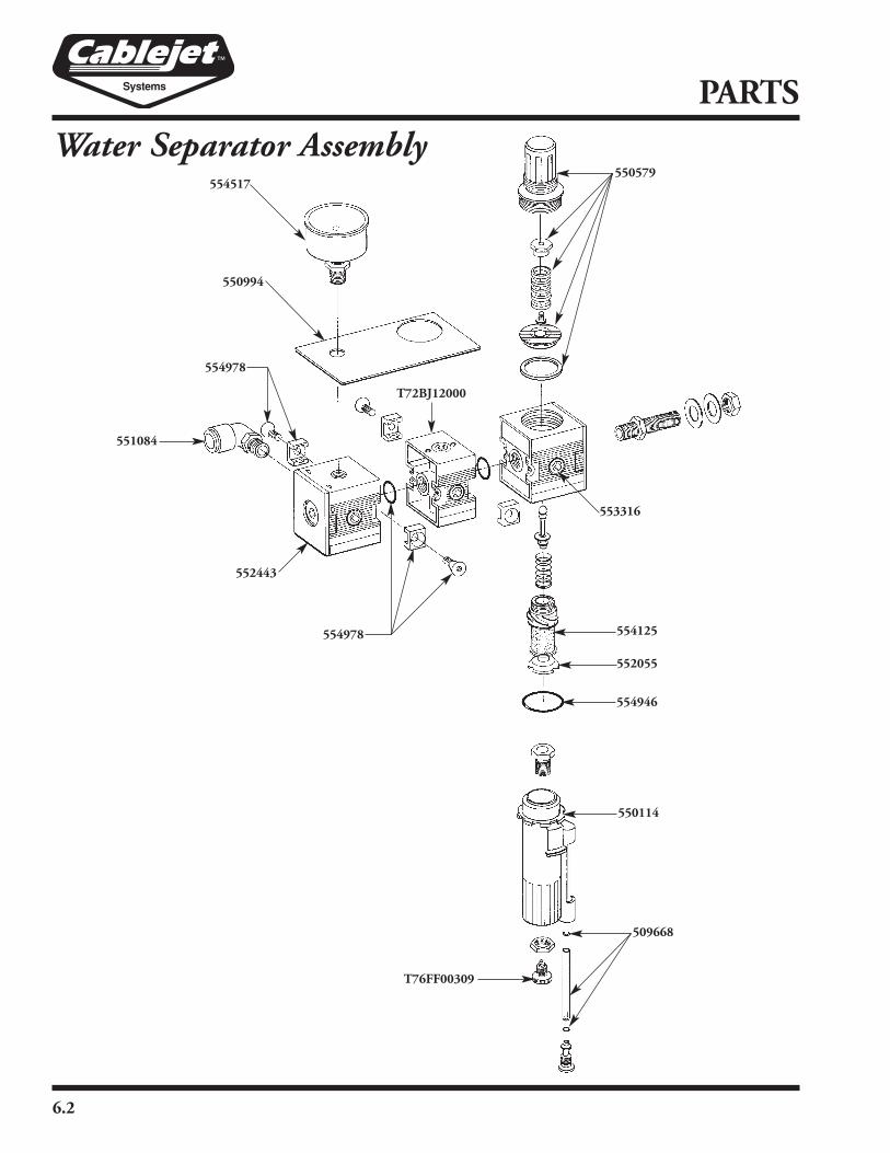
Water Separator Assembly554517
550579
551084
554978
550994
553316
T72BJ12000
552443
554125
552055
554946
550114
509668
554978
T76FF00309
6.3
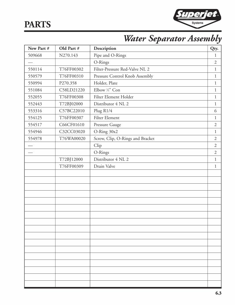
New Part # Old Part # Description Qty.
509668 N270.143 Pipe and O-Rings 1
— O-Rings 2
550114 T76FF00302 Filter-Pressure Red-Valve NL 2 1
550579 T76FF00310 Pressure Control Knob Assembly 1
550994 P270.358 Holder, Plate 1
551084 C58LD21220 Elbow 1⁄4" Con 1
552055 T76FF00308 Filter Element Holder 1
552443 T72BJ02000 Distributor 4 NL 2 1
553316 C57BC22010 Plug R1/4 6
554125 T76FF00307 Filter Element 1
554517 C66CF01610 Pressure Gauge 2
554946 C32CC03020 O-Ring 30x2 1
554978 T76WA00020 Screw, Clip, O-Rings and Bracket 2
— Clip 2
— O-Rings 2
T72BJ12000 Distributor 4 NL 2 1
T76FF00309 Drain Valve 1
PARTS
Water Separator Assembly
6.3

6.4
PARTS
Lubricator Assembly554517
551368
C58UB00820
509669
554978
554946
509668
553922
554978551084
552443
PARTS
Lubricator Assembly
6.5
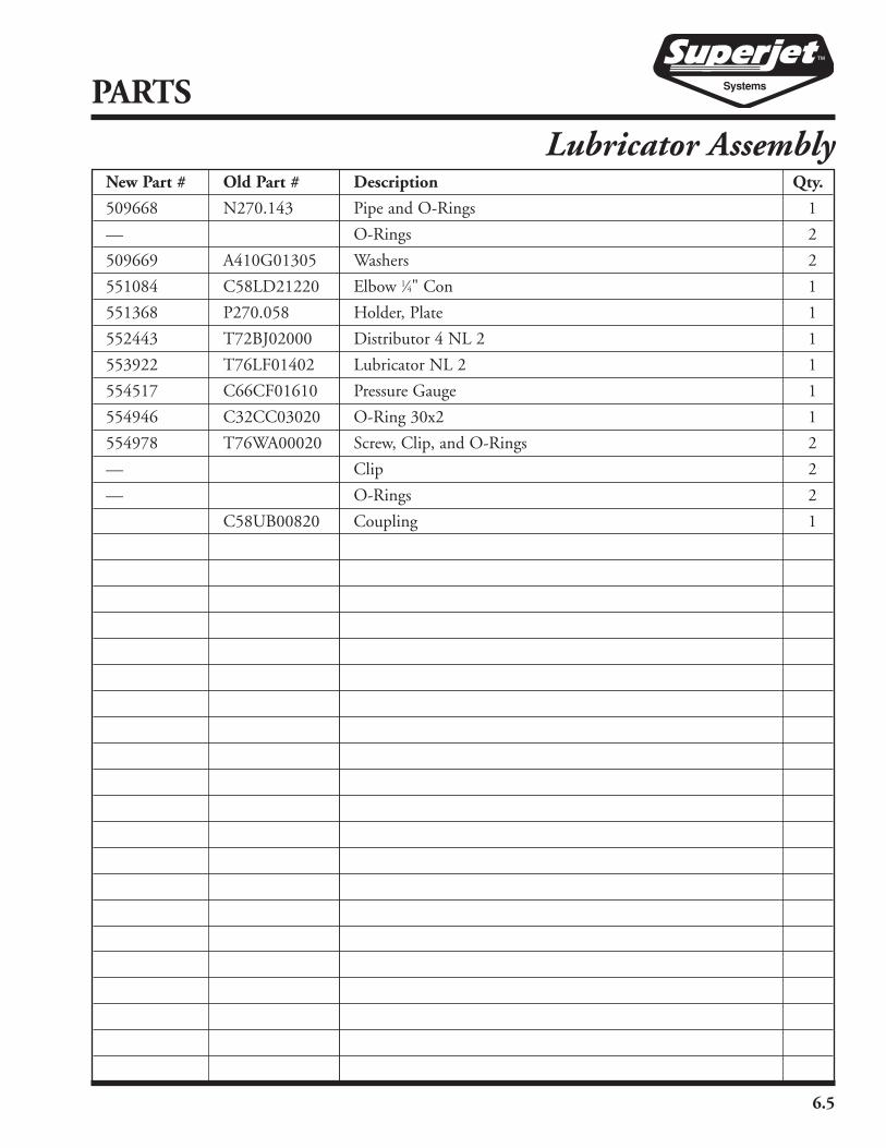
New Part # Old Part # Description Qty.
509668 N270.143 Pipe and O-Rings 1
— O-Rings 2
509669 A410G01305 Washers 2
551084 C58LD21220 Elbow 1⁄4" Con 1
551368 P270.058 Holder, Plate 1
552443 T72BJ02000 Distributor 4 NL 2 1
553922 T76LF01402 Lubricator NL 2 1
554517 C66CF01610 Pressure Gauge 1
554946 C32CC03020 O-Ring 30x2 1
554978 T76WA00020 Screw, Clip, and O-Rings 2
— Clip 2
— O-Rings 2
C58UB00820 Coupling 1

6.6
PARTS
11⁄4" and 2" Air Cutoff Valve
551618
555755
553375
550932
553375
551618
552787
552354
555012
555012
555012
552354
554032

6.7
New Part # Old Part # Description Qty.
550932 5-340-004 Clip, Safety, Air King No. AC1 8
551618 5-339-004 Coupling, Universal Air, Air King No. AM-12 3
552354 5-722-004 Coupling, Universal Air 2", Air King 3
552787 1-474-004 Bushing, 11⁄4" NPT Male – 1" NPT Female Brass 1
553375 C58VJ02000 Large Rubber Grommets 3
554032 4-394-004 Valve, Ball w/Lever Handle, 11⁄4" 90° Open, NPT 1
555012 5-723-004 Nipple, 11⁄4" NPT x Close Brass 2
555755 4-238-004 Valve, Ball w/Lever Handle, 1" 90° Open, 1" NPT 1
PARTS
11⁄4" and 2" Air Cutoff Valve

6.8
PARTS
1", 11⁄4", 11⁄2", 2" Air Cutoff Valve
551618
553947
552905
553375
550932
555755
554317
552787
554466
552250555012
554032553088
552905
553947
550932551332552354
552250555012

6.9
New Part # Old Part # Description Qty.
550028 5-756-004 Air Valve Assembly, 2" (11⁄2") 1
550932 5-340-004 Clip, Safety, Air King No. AC1 2
551332 5-716-004 Coupling, Universal Air 2", Air King AM-23 1
551618 5-339-004 Coupling, Universal Air, Air King No. AM-12 1
551706 5-755-004 Air Valve Assembly, 2" (11⁄4") 1
551919 5-754-004 Air Valve Assembly, 1" 1
552250 5-718-004 Nipple, 11⁄2" NPT x Close Brass 1
552354 5-722-004 Coupling, Universal Air 2", Air King No. AM-18 1
552787 1-474-004 Bushing, 11⁄4" NPT Male - 1" NPT Female Brass 1
552905 2-529-004 Elbow, 1⁄8" NPT 45 1
553088 5-717-004 Ball Valve, w/Lever Handle, 11⁄2" 90° Open NPT 1
553375 C58VJ02000 Large Rubber Grommet 1
553947 5-414-004 Gauge, Air Monnier 13524, 1-160 PSI, 1.5" Face, 1⁄8" NPT 1
554032 4-394-004 Ball Valve, w/Lever Handle, 11⁄4" 90° Open NPT 1
554317 5-431-004 Nipple, 1" NPT x Close Brass 1
554466 5-719-004 Bushing, 11⁄2" NPT Male - 11⁄4" NPT Female Brass 1
555012 5-723-004 Nipple, 11⁄4" NPT x Close Brass 1
555755 4-238-004 Ball Valve, w/Lever Handle, 1" 90° Open, 1" NPT 1
PARTS
1", 11⁄4", 11⁄2", 2" Air Cutoff Valve

6.10
PARTS
Base Plate and Air Motor Assembly555175
554488
553537
550994550096
509673
551964
554138
509671
551635
553037550693 550693
551545
551315
553164
551084
551084
553764
550025
554547
551084
550462
555784
550462
554038
550926
509670
552594
552594552125
552748
509672
559306
552963
550693
550796
552179
KEY
550017
553835
6.11
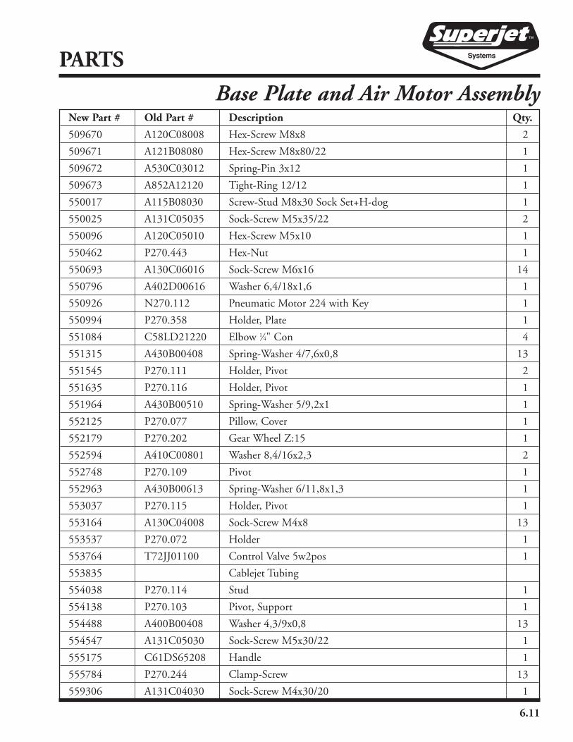
New Part # Old Part # Description Qty.
509670 A120C08008 Hex-Screw M8x8 2
509671 A121B08080 Hex-Screw M8x80/22 1
509672 A530C03012 Spring-Pin 3x12 1
509673 A852A12120 Tight-Ring 12/12 1
550017 A115B08030 Screw-Stud M8x30 Sock Set+H-dog 1
550025 A131C05035 Sock-Screw M5x35/22 2
550096 A120C05010 Hex-Screw M5x10 1
550462 P270.443 Hex-Nut 1
550693 A130C06016 Sock-Screw M6x16 14
550796 A402D00616 Washer 6,4/18x1,6 1
550926 N270.112 Pneumatic Motor 224 with Key 1
550994 P270.358 Holder, Plate 1
551084 C58LD21220 Elbow 1⁄4" Con 4
551315 A430B00408 Spring-Washer 4/7,6x0,8 13
551545 P270.111 Holder, Pivot 2
551635 P270.116 Holder, Pivot 1
551964 A430B00510 Spring-Washer 5/9,2x1 1
552125 P270.077 Pillow, Cover 1
552179 P270.202 Gear Wheel Z:15 1
552594 A410C00801 Washer 8,4/16x2,3 2
552748 P270.109 Pivot 1
552963 A430B00613 Spring-Washer 6/11,8x1,3 1
553037 P270.115 Holder, Pivot 1
553164 A130C04008 Sock-Screw M4x8 13
553537 P270.072 Holder 1
553764 T72JJ01100 Control Valve 5w2pos 1
553835 Cablejet Tubing
554038 P270.114 Stud 1
554138 P270.103 Pivot, Support 1
554488 A400B00408 Washer 4,3/9x0,8 13
554547 A131C05030 Sock-Screw M5x30/22 1
555175 C61DS65208 Handle 1
555784 P270.244 Clamp-Screw 13
559306 A131C04030 Sock-Screw M4x30/20 1
PARTS
Base Plate and Air Motor Assembly
6.12
PARTS
Air Inlet and Drive Roller Assembly
552660
553098
509676
509679
553671
550711
509675
559483551010
555409
509677
509677
555409555404
559483551010
509675
550711
553671
550394
553098
552660
509676
554818
550684
550693
509678
509674
552503
552477
550462
554495
509680
552631
554569
550842
551309
551624
551084
550684
6.13
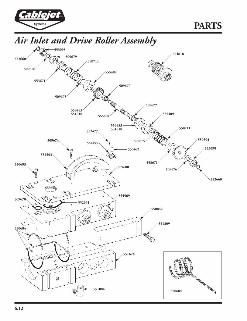
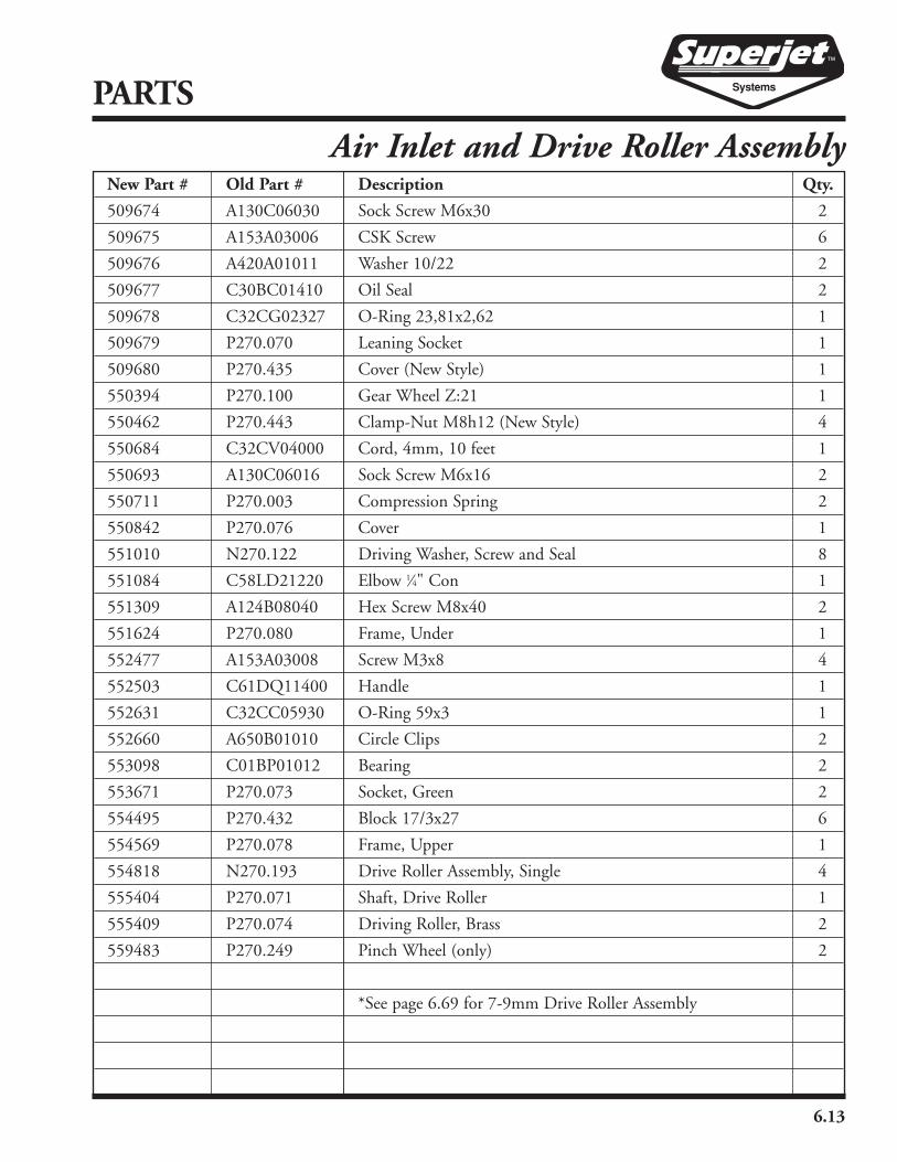
New Part # Old Part # Description Qty.
509674 A130C06030 Sock Screw M6x30 2
509675 A153A03006 CSK Screw 6
509676 A420A01011 Washer 10/22 2
509677 C30BC01410 Oil Seal 2
509678 C32CG02327 O-Ring 23,81x2,62 1
509679 P270.070 Leaning Socket 1
509680 P270.435 Cover (New Style) 1
550394 P270.100 Gear Wheel Z:21 1
550462 P270.443 Clamp-Nut M8h12 (New Style) 4
550684 C32CV04000 Cord, 4mm, 10 feet 1
550693 A130C06016 Sock Screw M6x16 2
550711 P270.003 Compression Spring 2
550842 P270.076 Cover 1
551010 N270.122 Driving Washer, Screw and Seal 8
551084 C58LD21220 Elbow 1⁄4" Con 1
551309 A124B08040 Hex Screw M8x40 2
551624 P270.080 Frame, Under 1
552477 A153A03008 Screw M3x8 4
552503 C61DQ11400 Handle 1
552631 C32CC05930 O-Ring 59x3 1
552660 A650B01010 Circle Clips 2
553098 C01BP01012 Bearing 2
553671 P270.073 Socket, Green 2
554495 P270.432 Block 17/3x27 6
554569 P270.078 Frame, Upper 1
554818 N270.193 Drive Roller Assembly, Single 4
555404 P270.071 Shaft, Drive Roller 1
555409 P270.074 Driving Roller, Brass 2
559483 P270.249 Pinch Wheel (only) 2
*See page 6.69 for 7-9mm Drive Roller Assembly
PARTS
Air Inlet and Drive Roller Assembly

New Part # Old Part # Description Qty.
509681 P270.309 Chain-Wheel Z:12 1
550080 P265.145 Hex Screw M8x55/22 2
550506 A131B06060 Sock-Screw M6x60/24 1
550573 A401B00816 Washer 8,4/15x1,6 1
550699 N265.042 Chain Wheel, Set 1
550720 A120C06016 Hex Screw M6x16 1
550748 C33KK02410 V-Seal 24-27/W4x9 1
6.14
PARTS
Upper Gear Case Assembly (DF21 Style)
554134
554827
554424
554316
554134 552747
553599 554134
553599552747
554539
552492
552279
551070
509681
552279551070
552123
552492 551307 550080555094
550748
553333
551588
553398551869
551588
550573
554333
551609550506
552963
550936
552963
550720
553770
552830555594
553708554489
552187553968
551062
554229
551206554238551558

6.15
New Part # Old Part # Description Qty.
550936 A410B00702 Washer 7/25x1,8 1
551062 P265.141 Spacing-Bushing 1
551070 C01BP01510 Ball Bearing 15/32x9 2rs 2
551206 P265.201 Washer 2
551307 A430A00816 Spring-Washer 8/14,9x1,6 2
551558 P265.200 Spacing-Bushing 2
551588 C61DF03530 Spheric Handle 35/10 2
551609 P265.215 Gear-Case, Upper 1
551869 P265.144 Barrel 1
552123 P265.116 Slide-Bar 2
552187 A150B05012 CSK Screw M5x12 Cross 4
552279 P265.168 Spacing-Bushing 2
552492 A152A06018 CSK Screw M6x18 Sock Head 10
552747 5-343-004 Quick Connect 3⁄8" Female ANV-38-NPT-F 3
552830 P270.309 Chain Wheel Z:12 Hydraulic Superjet Only 1
552963 A430A00613 Spring-Washer 6/11,8x1,3 2
553333 P265.165 Adjusting-Nut 1
553398 P265.167 Tightening Fork 1
553599 5-342-004 Quick Connect 3⁄8" Male ANV-38-NPT-M 3
553708 A600A05520 Flat Key 5/5x20A Pneumatic Superjet Only 1
553770 C37BD06320 Plug 1
553968 P265.195 Chain-Guide 1
554134 5-413-004 Hose Assy #6JIC Female Swivel Both Ends x60" long 2
554229 P265.122 Holder, Guiding, Upper 1
554238 P265.202 Washer 2
554316 5-412-004 Hose Assy #6JIC Female Swivel Both Ends x25" long 1
554333 A300C00800 Hex Nut M8 2
554424 5-411-004 3⁄8" British Standard Pipe Male w/O-Ring #6JIC Male 4
554489 P265.203 Key Hydraulic Superjet Only 1
554539 P265.213 Flange, Hydraulic Motor Only 2
554827 T08RE19331 Hydraulic Motor Danfoss OMM32 2
555094 P265.119 Block-Guide 1
555138 5-753-004 Extension Hose Assembly Complete w/Fittings, 10' 2
555594 P270.309 Chain Wheel Z:12 Pneumatic Superjet Only 1
PARTS
Upper Gear Case Assembly (DF21 Style)

6.16
PARTS
Lower Gear Case and Chain Assembly (DF21 Style)
New Part # Old Part # Description Qty.
304873 SJ-1 Stabilizing Foot 2
509681 P265.133 Chain-Wheel Z:12 1
550573 A401B00816 Washer 8,4/15x1,6 1
550699 N265.042 Chain Wheel, Set 1
550720 A120C06016 Hex Screw M6x16 1
550936 A410B00702 Washer 7/25x1,8 1
552321
552279
551941
551070
509681
553987
554852
552187 553968
552953
550573
554333
553398
552279
551070
550955
555217
552492
555711
553525555300
553708554489
552830553770
550720
552963
550936
552344
555002554686
553251
554169 555045
555270
554944
304873553246
555412
551715

6.17
New Part # Old Part # Description Qty.
550955 A100B00811 Stud M8x35/10/22 3
551070 C01BP01510 Ball Bearing 15/32x9 2rs 2
551715 Connecting Link
552187 A150B05012 CSK Screw M5x12 Cross 4
551941 P265.117 Slide 1
552279 P265.168 Spacing-Bushing 2
552321 N265.049 Chain 2 12,7/7,75x8,51-63, with Master Link 1
552344 P265.089 Fork, Guiding 1
552492 A152A06018 CSK Screw M6x18 Socket Head 4
552830 P270.309 Chain Wheel Z:12, Hydraulic Superjet Only 1
552953 P265.164 Rope Guide, Green 2
552963 A430A00613 Spring-Washer 6/11,8x1,3 1
553246 P265.214 Gear-Case, Under 1
553251 5-466-004 Screw 12mm x 30 2
553525 A430A00510 Spring-Washer 5/9,2x1 8
553398 P265.167 Tightening Fork 1
553708 A600A05520 Flat Key 5/5x20A Pneumatic Superjet Only 1
553770 C37BD06320 Plug 1
553968 P265.195 Chain-Guide 1
553987 T53LS22612 Snap-On V-Shaped Rubber 1
554169 Circle Clip 15 x 1
554333 A300C00800 Hex Nut M8 2
554489 P265.203 Key, Hydraulic Superjet Only 1
554686 A100B00820 Stud 3
554852 A120F05008 Hex Screw M5x8 8
554944 5-353-004 Bumper, Rubber Stud, McMaster 9377 K42 4
555002 A305B00800 Hex Nut M8 3
555045 Washer 15/28 x 2.5
555217 P265.115 Slide-Bar 2
555270 3-651-004 Nut, HH Lock, 5⁄16" UNC, STL, Pltd 4
555300 A130C05010 Sock Screw M5x10 Head Cap 8
555412 P265.209 Rope Guide, Hydraulic and Pneumatic Superjet 1
555594 P270.309 Chain Wheel Z:12, Pneumatic Superjet Only 1
555711 P265.166 Holder, Guiding, Under 1
PARTS
Lower Gear Case and Chain Assembly (DF21 Style)

6.18
PARTS
Upper Gear Case and Chain (DF22 Style)
555094
550080
550748
551307
553333
551588551869
509683
554873555519
552738
552123
555469
509684
555388
550720
552963
550936
552830
551277
551516
555770
550239
553968
509681
551070
553876
554169
551203
509682
552594
552490
552321
553987
New Part # Old Part # Description Qty.
509681 P265.133 Chain Wheel 1
509682 A311B00800 Nut 1
551715
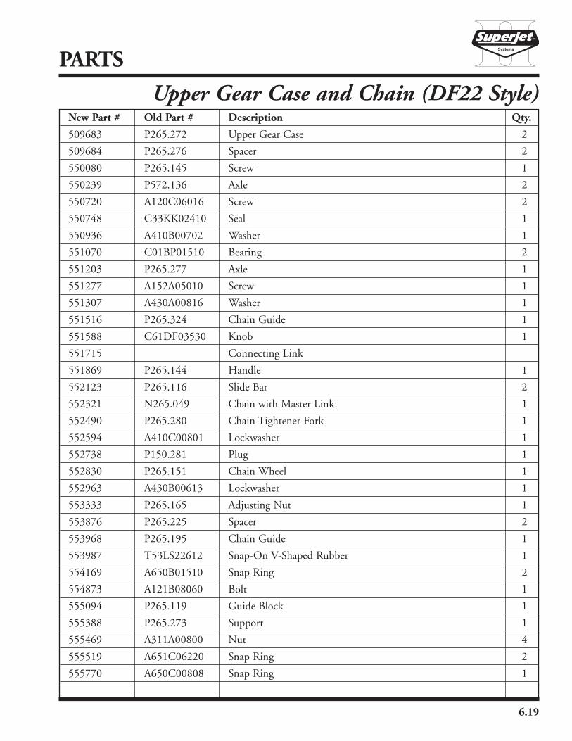
6.19
PARTS
New Part # Old Part # Description Qty.
509683 P265.272 Upper Gear Case 2
509684 P265.276 Spacer 2
550080 P265.145 Screw 1
550239 P572.136 Axle 2
550720 A120C06016 Screw 2
550748 C33KK02410 Seal 1
550936 A410B00702 Washer 1
551070 C01BP01510 Bearing 2
551203 P265.277 Axle 1
551277 A152A05010 Screw 1
551307 A430A00816 Washer 1
551516 P265.324 Chain Guide 1
551588 C61DF03530 Knob 1
551715 Connecting Link
551869 P265.144 Handle 1
552123 P265.116 Slide Bar 2
552321 N265.049 Chain with Master Link 1
552490 P265.280 Chain Tightener Fork 1
552594 A410C00801 Lockwasher 1
552738 P150.281 Plug 1
552830 P265.151 Chain Wheel 1
552963 A430B00613 Lockwasher 1
553333 P265.165 Adjusting Nut 1
553876 P265.225 Spacer 2
553968 P265.195 Chain Guide 1
553987 T53LS22612 Snap-On V-Shaped Rubber 1
554169 A650B01510 Snap Ring 2
554873 A121B08060 Bolt 1
555094 P265.119 Guide Block 1
555388 P265.273 Support 1
555469 A311A00800 Nut 4
555519 A651C06220 Snap Ring 2
555770 A650C00808 Snap Ring 1
Upper Gear Case and Chain (DF22 Style)

6.20
PARTS
Lower Gear Case and Chain (DF22 Style)
552963
555217
554944
552882
550720
552492
551761
509686
553251
304873
554686
555270 555519
552738
509684
555388
550720
552963
550936
552830
509685
553968
552953
551761551070
553876
554169
551203
555469
552594552490
509681
551941
552321
553987
551715

6.21
PARTS
New Part # Old Part # Description Qty.
304873 SJ-1 Stabilizer 2
509681 P265.133 Chain Wheel 1
509684 P265.276 Spacer 2
509685 A139B04010 Screw 1
509686 P265.271 Lower Gear Case 1
550720 A120C06016 Screw 2
550936 A410B00702 Washer 1
551070 C01BP01510 Bearing 2
551203 P265.277 Axle 2
551715 Connecting Link 1
551761 P265.278 Guard 3
551941 P265.117 Slide 1
552321 N265.049 Chain with Master Link 2
552490 P265.282 Chain Tightener Fork 1
552492 A152A06018 Screw 1
552594 A410C00801 Lockwasher 1
552738 P150.281 Plug 1
552830 P265.151 Chain Wheel 1
552882 P265.282 Stop 3
552953 P265.164 Rope Guide 1
552963 A430B00613 Lockwasher 2
553251 5-466-004 Hex Head Cap Screw 2
553876 P265.225 Spacer 1
553968 P265.195 Slide Pad 1
553987 T53LS22612 Snap-On V-Shaped Rubber 1
554169 A650B01510 Snap Ring 1
554686 A100B00820 Stud 3
554944 5-353-004 Rubber Bumper 4
555217 P265.115 Slide Guide 1
555270 3-651-004 Nut 8
555388 P265.273 Support 4
555469 A311B00800 Nut 2
555519 A651C06220 Snap Ring 2
Lower Gear Case and Chain (DF22 Style)

New Part # Old Part # Description Qty.
550699 N265.042 Chain Wheel Set 1
*Included in set
6.22
PARTS
Chain Wheel Set*
*
*

6.23
550305
550305
555230
555230
551344
551344
555836
552461
554921
553393 555230
550305
551344
551344
551344
555230
551344550305
550716
552666
509687
550053
New Part # Old Part # Description Qty.
509687 T76SB00410 Damper G 1⁄8" 1
550053 P265.205 Lever, Right 1
550305 P265.137 Screw M10x22 2
550716 T44DC05050 Pneumatic Thruster 2-Action 50x50 1
551344 P265.134 Screw 4
552461 P265.127 Lever, Left 1
552666 5-460-004 1⁄8" NPT Male, 3⁄8" OD Tee 1
553393 P265.123 Lever, Right 1
554921 P265.127 Lever, Left 1
555230 P265.146 Washer 12/18x0,5 2
555836 N265.034 Pressure Tube 1
PARTS
Hydraulic and Pneumatic Pressure Tube Assembly

6.24
PARTS
Pneumatic Motor and Air Fittings
555270
552199
554944
553613
551031
553613
551942
555002550624
553190
555412
554654
554753
553613
551623
554115
509688
KEY

6.25
New Part # Old Part # Description Qty.
509688 P270.359 Flange, Air Motor 2
550624 P264.008 Spacing-Bushing 3
551031 5-458-004 1⁄4" NPT Female Tee 1
551623 5-563-004 3⁄8" OD Plastic Tubing 3ft
551942 5-456-004 Coupling, Quick Connect 1
552199 5-457-004 1⁄2" NPT Male, 1⁄4" NPT Male, Straight Adapter 1
553190 P270.318 Holder 1
553613 5-459-004 1⁄4" NPT Male, 3⁄8" OD Tube 90° 4
554115 5-462-004 Air Muffler, Allied Witan No. B28 2
554654 A130C06012 Sock-Screw M6x12 8
554753 N270.232 Pneumatic Motor 226 (Key Included) 2
554944 5-353-004 Bumper, Rubber Stud, McMaster C 9377 K42 4
555002 A305B00800 Hex Nut M8 3
555270 3-651-004 Nut, HH Lock, 5⁄16" UNC, STL, Pltd 4
555412 P265.209 Rope Guide, Hydraulic and Pneumatic Superjet 1
PARTS
Pneumatic Motor and Air Fittings
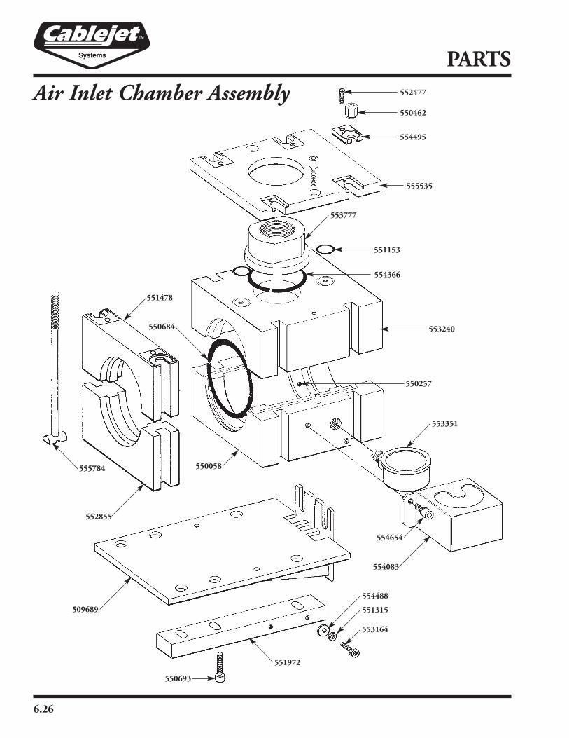
6.26
PARTS
Air Inlet Chamber Assembly
553777
555784
509689
551972
550684
554366
552477
550462
554495
555535
551153
553240
550257
554654
554083
553351
552855
551478
550693
553164
551315
554488
550058

6.27
New Part # Old Part # Description Qty.
509689 P270.138 Holder 1
550058 P270.409 Holder, Rope-Guide, Under 1
550257 A374D00609 Threaded Socket
550462 P270.443 Clamp-Nut M8h12 4
550684 C32CV04000 Cord 4 NBR70SH A (10 feet) 1
550693 A130C06016 Sock-Screw M6x16 2
551153 C32CG01526 O-Ring 15,08x2,62 4
551315 A430B00408 Spring-Washer 4/7,6x0,8 6
551478 P270.437 Half Flange, Upper (New Style) 1
551972 P270.140 Pivot Holder 1
552477 A153A03008 Screw M3x8 4
552855 P270.084 Half Flange, Under 1
553164 A130C04008 Sock-Screw M4x8 6
553240 P270.085 Holder, Rope Guide, Upper 1
553351 C66CP01600 Pressure Gauge 16 Bar 1
553777 P270.137 Connection 1
554083 P270.407 Protection, Gauge 1
554366 C32CC05740 O-Ring 57x4 1
554488 A400B00408 Washer 4,3/9x0,8 6
554495 P270.432 Block 17/3x27 4
554654 A130C06012 Sock-Screw M6x12 HD Cap 2
555535 P270.434 Cover (New Style) 1
555784 P270.244 Clamp-Screw (Sold four per pack) 4
PARTS
Air Inlet Chamber Assembly

6.28
PARTS
Footage Counter/Speed Indicator
A141B05010
P270.510
A131C04040
554495
552477
550693
553083
559818
A115B06016
P270.212
A116C06010
P270.213
P270.211
P270.246
555770 C15HD01251
E451010003
P270.512
C01BN00810
P177.659
550462
P270.511

6.29
PARTS
New Part # Old Part # Description Qty.
550462 P270.443 Clamp Nut 4
550693 A130C06016 Socket Screw 4
552202 N270.268 Conversion Kit for VL-10
552477 A153A03008 Screw 4
553083 P270.436 New Style Top Cover
553694 N270.267 New VL-10 Footage Counter Complete
554495 P270.432 Block 4
555770 A650C00808 Snap Ring 4
559504 CR126005E 3V Lithium Battery 1
559818 N403.000 Counter VL110 1
A115B06016 Screw 1
A116C06010 Screw 1
A131C04040 Screw 4
A141B05010 Screw 4
C01BN00810 Bearing Bushing 2
C15HD01251 Bearing Bushing 2
E451010003 Magnet 2
P177.659 Spring 1
P270.211 Spacer Bushing 1
P270.212 Pivot Pin 1
P270.213 Frame 1
P270.246 Spindle 1
P270.510 Adapter 2
P270.511 Lever 1
P270.512 Sensor Roller 1
Footage Counter/Speed Indicator

6.30
PARTS
Exhaust Chamber, Upper and Lower
509690
550773
552477
550462
554495
550693
550058
554366555784
551478
552855
509689
551972
550693
553164
551315554488
554357
553240
555535

6.31
New Part # Old Part # Description Qty.
509689 P270.138 Holder 1
509690 P270.010 Connection, Exhaust 1
550058 P270.409 Holder, Rope Guide, Lower 1
550462 P270.443 Clamp-Nut M8h12 4
550693 A130C06016 Sock-Screw M6x16 2
550773 P270.011 Exhaust Tube 1
— O-Ring (Included with Item 550773) 1
— Lower Mount (Included with Item 550773) 1
551315 A430B00408 Spring-Washer 4/7,6x0,8 6
551478 P270.437 Half-Flange, Upper 1
551972 P270.140 Pivot Holder 2
552477 A153A03008 Screw M3x8 4
552855 P270.084 Half Flange, Under 1
553164 A130C04008 Sock-Screw M4x8 6
553240 P270.085 Holder, Rope Guide, Upper 1
554357 A501C06050 Cylinder Pin 4
554366 C32CC05740 O-Ring 57x4 1
554488 A400B00408 Washer 4,3/9x0,8 6
554495 P270.432 Block 17/3x27 4
555535 P270.434 Cover (New Style) 1
555784 P270.244 Clamp-Screw (Sold four per pack) 6
PARTS
Exhaust Chamber, Upper and Lower

6.32
PARTS
Air Control Module Controls
551863
550434554290
551718
555042
554958
552136
551994
554865
550570
553560
550776
555263
550625
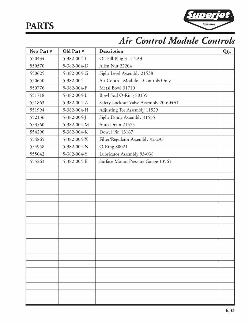
6.33
New Part # Old Part # Description Qty.
550434 5-382-004-I Oil Fill Plug 31512A3
550570 5-382-004-D Allen Nut 22204
550625 5-382-004-G Sight Level Assembly 21538
550650 5-382-004 Air Control Module – Controls Only
550776 5-382-004-F Metal Bowl 31710
551718 5-382-004-L Bowl Seal O-Ring 80135
551863 5-382-004-Z Safety Lockout Valve Assembly 20-604A1
551994 5-382-004-H Adjusting Tee Assembly 11529
552136 5-382-004-J Sight Dome Assembly 31535
553560 5-382-004-M Auto Drain 21575
554290 5-382-004-K Dowel Pin 13167
554865 5-382-004-X Filter/Regulator Assembly 92-293
554958 5-382-004-N O-Ring 80021
555042 5-382-004-Y Lubricator Assembly 93-038
555263 5-382-004-E Surface Mount Pressure Gauge 13561
PARTS
Air Control Module Controls
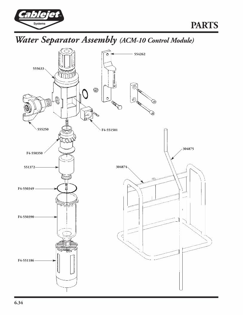
6.34
PARTS
Water Separator Assembly (ACM-10 Control Module)
F4-550350
F4-550349
551372
F4-550390
F4-551186
304875
555633
555250
554262
F4-551501
304874

6.35
New Part # Old Part # Description Qty.
304874 CS-4 Control Stand Weldment 1
304875 CS-7 Control Stand Rod 1
555633 5-382-004-C Regulator, Filter with Float #703-W3000-10N 1
554262 5-385-004 T-Bracket Assembly 2
555250 5-386-004 Air King AMB-3⁄8" NPT Male 1
551372 5-946-004 F4-550678 Flout Drain 1
F4-550349 O-Ring, Bowl 1
F4-550350 Element, Standard 5 Micron 1
F4-550390 Bowl, Poly 1
F4-551186 Bowl, Guard 1
F4-551501 Pressure Gauge 1
PARTS
Water Separator Assembly (ACM-10 Control Module)

6.36
PARTS
Lubricator Assembly (ACM-10 Control Module)
551430
F3-550349
F3-550330
F3-551220
Fill Plug
F4-550091
553894 550278
554907
550278
550703
Adjusting Dome

6.37
New Part # Old Part # Description Qty.
550278 5-388-004 Hose 1
550703 5-384-004 Valve, Lock Out, Miller #703-V3010-10N 1
551430 5-383-004 Lubricator, Miller #703-L3000-10N 1
553894 5-389-004 Connect, Quick, Faster Male #TNL-08-NPT-M 1
554907 5-387-004 Fitting 1
F3-550330 Bowl, Poly 1
F3-550349 O-Ring, Bowl 1
F3-551220 Bowl, Guard
F4-550091 O-Ring, Fill Plug 1
— Adjusting Dome 1
— Fill Plug 1
PARTS
Lubricator Assembly (ACM-10 Control Module)

6.38
PARTS
Air Cooler Assembly304878
304877
304876
553967
552523
550207
552196
550957
552193
550345
553298303580
300816
552343
303581/303582
550450555022
551886
550009
304879
553437
555441
554780
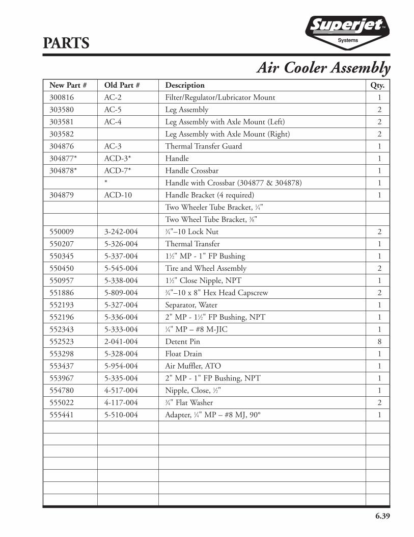
6.39
New Part # Old Part # Description Qty.
300816 AC-2 Filter/Regulator/Lubricator Mount 1
303580 AC-5 Leg Assembly 2
303581 AC-4 Leg Assembly with Axle Mount (Left) 2
303582 Leg Assembly with Axle Mount (Right) 2
304876 AC-3 Thermal Transfer Guard 1
304877* ACD-3* Handle 1
304878* ACD-7* Handle Crossbar 1
* Handle with Crossbar (304877 & 304878) 1
304879 ACD-10 Handle Bracket (4 required) 1
Two Wheeler Tube Bracket, 1⁄4"
Two Wheel Tube Bracket, 3⁄8"
550009 3-242-004 3⁄4"–10 Lock Nut 2
550207 5-326-004 Thermal Transfer 1
550345 5-337-004 11⁄2" MP - 1" FP Bushing 1
550450 5-545-004 Tire and Wheel Assembly 2
550957 5-338-004 11⁄2" Close Nipple, NPT 1
551886 5-809-004 3⁄4"–10 x 8" Hex Head Capscrew 2
552193 5-327-004 Separator, Water 1
552196 5-336-004 2" MP - 11⁄2" FP Bushing, NPT 1
552343 5-333-004 1⁄4" MP – #8 M-JIC 1
552523 2-041-004 Detent Pin 8
553298 5-328-004 Float Drain 1
553437 5-954-004 Air Muffler, ATO 1
553967 5-335-004 2" MP - 1" FP Bushing, NPT 1
554780 4-517-004 Nipple, Close, 1⁄2" 1
555022 4-117-004 3⁄4" Flat Washer 2
555441 5-510-004 Adapter, 1⁄4" MP – #8 MJ, 90° 1
PARTS
Air Cooler Assembly

6.40
PARTS
Filter/Regulator/Lubricator Assembly (AC-10)
552482
F4-551186
F4-550349
F4-550350
554957
552902
554262
F4-551501
551430
552902
552305
554780
F4-550091
F3-550349
F3-550330
F3-551228
Adjusting Dome

6.41
New Part # Old Part # Description Qty.
551778 5-329-004-C Filter/Regulator/Lubricator Assembly, Complete *
551430 5-383-004 Lubricator, Miller 703-L3000-10 N 1
551535 5-329-004 Complete New Filter, Regulator, Lubricator Assy 1
552305 5-330-004 Valve, Brass Ball with Lever Handle 1⁄2" 1
552482 5-331-004 3⁄8" 100R2, #8FS-JIC, #8FS-JIC, 17" 1
554780 4-517-004 #8 Close Nipple, NPT 1
552902 5-334-004 8MP, 8MJ 90° 2
554262 5-385-004 “T” Bracket Assembly 2
554957 5-332-004 3⁄8" 100R2, #8FS-JIC, #8FS-JIC, 20" 1
F3-550330 Bowl, Lubricator 1
F3-550349 O-Ring, Bowl 1
F3-551228 Guard, Bowl 1
F4-550091 O-Ring, Fill Plug 1
F4-550349 O-Ring, Bowl 1
F4-550350 Element, 5 Micron 1
F4-551186 Guard, Bowl 1
F4-551501 Gauge, Pressure 1
Dome, Adjusting 1
PARTS
Filter/Regulator/Lubricator Assembly (AC-10)
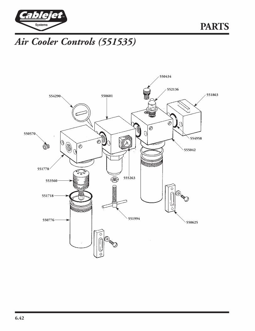
6.42
PARTS
Air Cooler Controls (551535)
551863554290
550434
555263
555042
554958
550601
550570
553560
551718
550776
551778
550625551994
552136
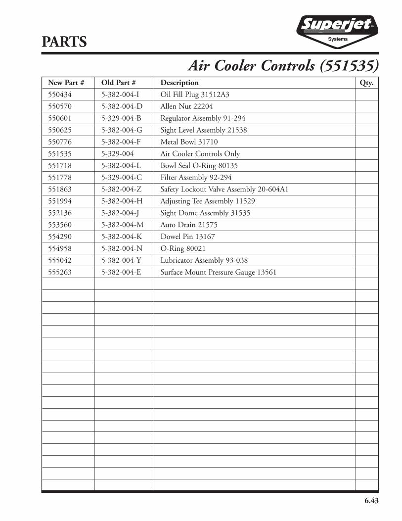
6.43
New Part # Old Part # Description Qty.
550434 5-382-004-I Oil Fill Plug 31512A3
550570 5-382-004-D Allen Nut 22204
550601 5-329-004-B Regulator Assembly 91-294
550625 5-382-004-G Sight Level Assembly 21538
550776 5-382-004-F Metal Bowl 31710
551535 5-329-004 Air Cooler Controls Only
551718 5-382-004-L Bowl Seal O-Ring 80135
551778 5-329-004-C Filter Assembly 92-294
551863 5-382-004-Z Safety Lockout Valve Assembly 20-604A1
551994 5-382-004-H Adjusting Tee Assembly 11529
552136 5-382-004-J Sight Dome Assembly 31535
553560 5-382-004-M Auto Drain 21575
554290 5-382-004-K Dowel Pin 13167
554958 5-382-004-N O-Ring 80021
555042 5-382-004-Y Lubricator Assembly 93-038
555263 5-382-004-E Surface Mount Pressure Gauge 13561
PARTS
Air Cooler Controls (551535)
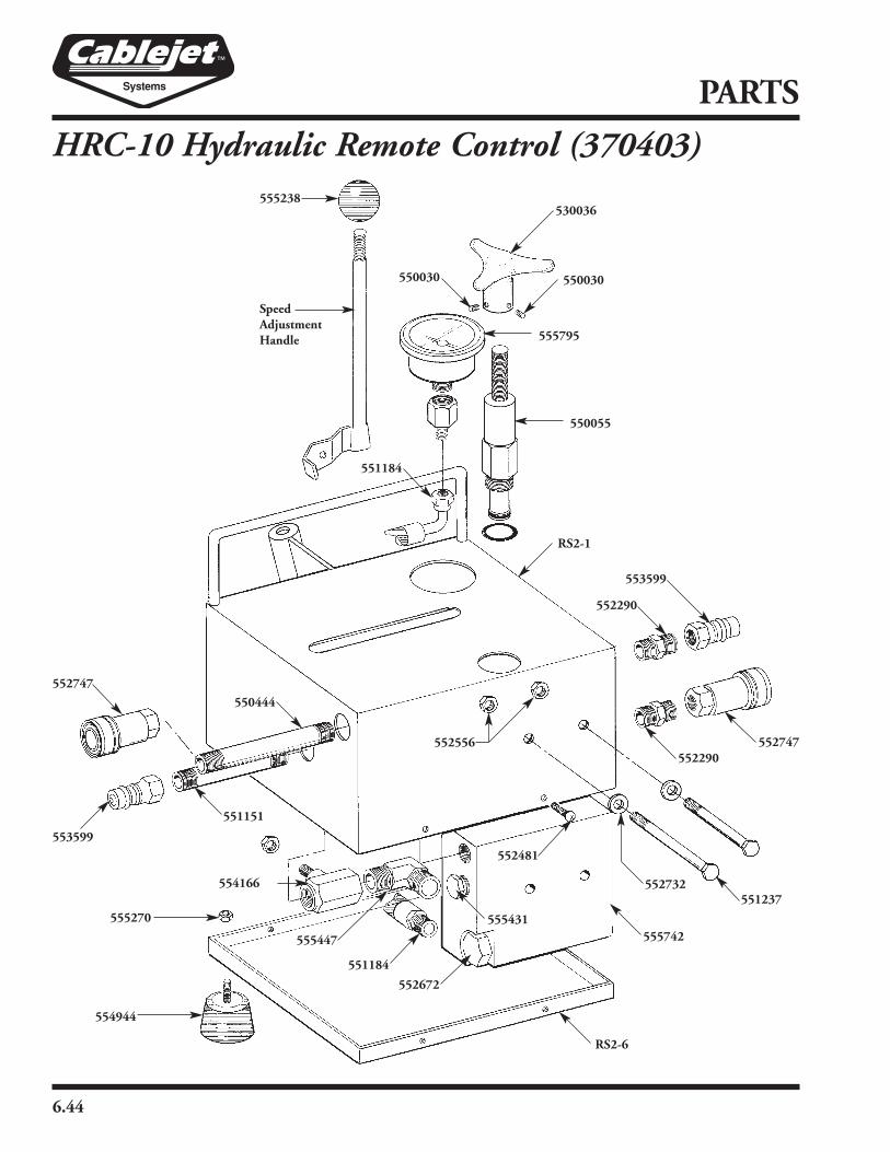
6.44
PARTS
HRC-10 Hydraulic Remote Control (370403)
SpeedAdjustmentHandle
530036
555795
550030 550030
550055
551184
RS2-1
552290
553599
552747552290
552481
RS2-6
555742
551184
555431
555447
554166
554944
555270
553599
551151
552747
550444
555238
552672
552732551237
552556

6.45
New Part # Old Part # Description Qty.
370403 HRC-10-5, Complete 1
530036 1-020-002 Hand Knob for AIA Machined for PP & HRC-10 1
550030 4-220-004 Screw, Set 10-32x1⁄4" Cup Point 2
550055 5-728-004 Relief Cartridge, HRC-10-5, DF-FCP-00-5.0 1
550444 5-348-004 Nipple, Black Pipe 3⁄8" NPT x 5" Long 1
551151 5-347-004 Nipple, Black Pipe 3⁄8" NPT x 31⁄2" Long 1
551184 5-350-004 Hose, 10" Long 1
551237 3-279-004 Bolt, 1⁄4" NF x 21⁄4" Long 2
551862 5-352-004 Decal Package - ID Products No. HRC-10 1
552290 5-344-004 Adapter, Straight 3⁄8" NPT Male-3⁄8" NPT Male 2
552481 Screw 1
552556 120-004 Nut, Hex Head, 1⁄4"-20 UNC, Steel Plated 2
552672 5-727-004 Flow Splitter Only, HRC-10-5, DF-FCP-00-5 1
552732 175-004 Washer, Lock 1⁄4" Steel Plated 2
552747 5-343-004 Quick Connect, 3⁄8" Female, ANV-38 NPT-F 2
553599 5-342-004 Quick Connect, 3⁄8" Male, ANV-38 NPT-M 2
554166 5-349-004 Valve, Steel Ball, 3⁄8" NPT Female 1
554944 5-353-004 Bumper, Rubber Stud, McMaster C9377 K42 4
555238 Handle Knob 1
555270 3-651-004 Nut, Hex Head Lock, 5⁄16" UNC, STL, PLTD 4
555431 5-345-004 Plug, Hex Head 3⁄8" NPT 2
555447 5-346-004 Fitting, 3⁄8" NPT Male-3⁄8" NPT Male 90° 1
555742 5-341-004 Manifold, HRC-10 1
555795 5-351-004 Gauge, Pressure, 0-2000 PSI, Wika 1
RS2-1 Housing Weldment 1
RS-6 Housing Cover Weldment 1
— Speed Adjustment Handle 1
HRC-10 Hydraulic Remote Control (370403)
PARTS

6.46
PARTS
New Part # Old Part # Description Qty.
530056 1-020-002 Hand Knob 1
550020 5-399-004 Fitting, 3⁄8" MP x #6 MJ 2
550030 4-220-004 Screw, Set 10-32 x 1⁄4" Cup Point 2
550204 5-404-004 Hose, 3⁄8" x 10" Long (5.5HP) 1
550947 5-400-004 Fitting, 3⁄8" FP x 3⁄8" FP x 3⁄8" FP Tee 1
551118 5-689-004 Hose, 3⁄8" x 26" Long (8HP & 9HP) 1
551286 5-684-004 Relief Cartridge, Delta DE-RVD 00-2000 1
551591 5-291-004 Bushing, 3⁄8" MP x 1⁄4" FP 1
552183 5-394-004 Valve Body, Delta 30102006 1
552290 5-344-004 Adapter, 3⁄8" MP - 3⁄8" MP 2
552674 5-405-004 Hose, 3⁄8" x 181⁄2" Long (5.5HP) 1
552732 175-004 Washer, Lock 1⁄4" 2
553599 5-342-004 Quick Connect, 3⁄8" ANV - 38 NPT-M 1
553768 5-218-004 Fitting, 3⁄8" MP x 6 MJ 90° 1
554031 5-688-004 Hose, 3⁄8" x 15" Long (8HP & 9HP) 1
554166 5-349-004 Valve, Steel Ball with Lever, 3⁄8" NPT 1
554750 2-282-004 Bolt, HHCS 1⁄4" NF x 2" 2
555335 5-393-004 Gauge, Pressure, 0-2000 PSI 1
555447 5-346-004 Fitting, 3⁄8" MP x 3⁄8" MP 90° 2
552674(5.5HP)
553768
550947
551591
555335
552290
550204(5.5HP)
550020
552183
530056
550030
551286
554166
552290 555447
552732 553599
554750
Control Valve Assembly
551118(8HP & 9HP)
554031(8HP & 9HP)

6.47
PARTS
New Part # Old Part # Description Qty.
550932 5-340-004 Clip, Safety Air King –
551618 5-339-004 Coupling, Universal Air King 1" MP 4
1" Rubber Grommet –
552354 5-722-004 Coupling, Universal 2" Air King 2
2" Rubber Grommet –
552632 6-036-004 Hose Assembly
553364 5-724-004 11⁄4" FP – 11⁄4" FP – 11⁄4" FP Tee 1
554986 3-525-004 16 FP – 16 FP – 16 FP Tee 1
555012 5-723-004 Nipple, 11⁄4" NPT Close, Bypass 2
550932
551618
554986
552354
555012
555012
552354
553364
551618
550932
551618
Oil Cooler/Air Supply Fittings
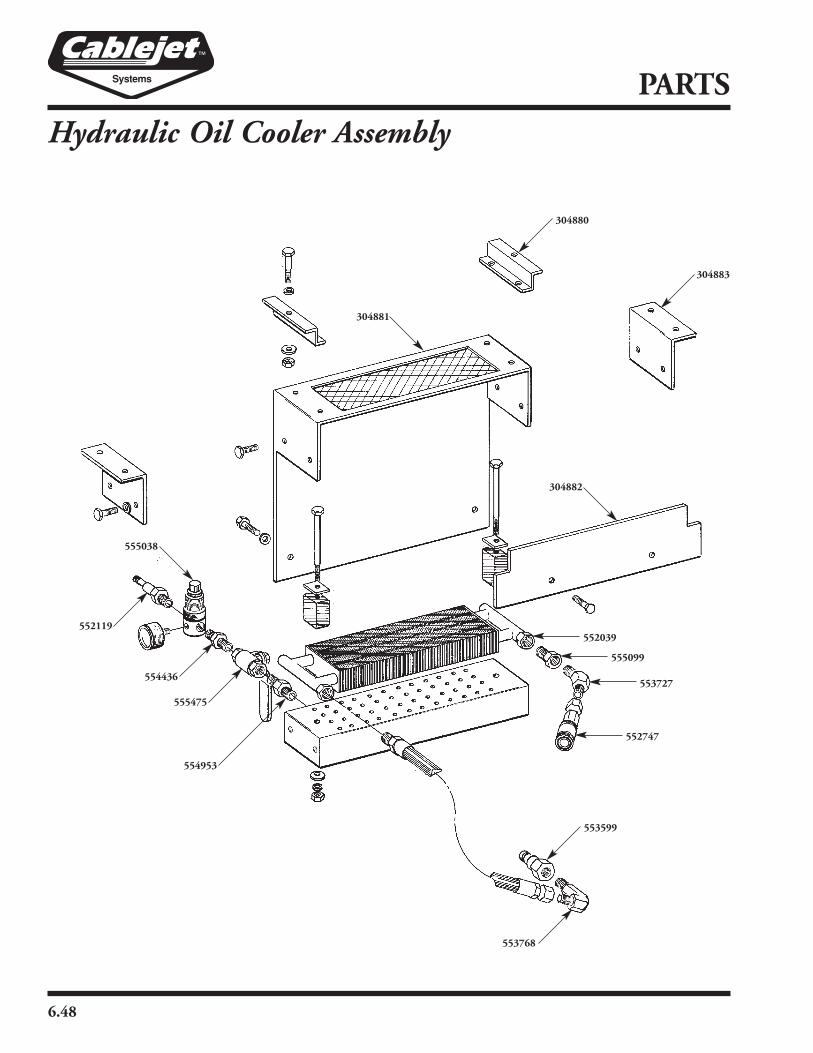
6.48
PARTS
Hydraulic Oil Cooler Assembly
304881
553599
304882
555038
552119
554436
555475
554953
553768
552747
553727
555099
552039
304883
304880

6.49
PARTS
New Part # Old Part # Description Qty.
304880 OC-6 5.5 HP/Clamp Mount 2
304881 OC-9 Cooler Cover Weldment 1
304882 OC-12 Fin Cover Plate 1
304883 OC-13 8HP/Clamp Mount 1
552039 5-657-004 Heat Exchanger 1
Rubber Mount 2
Bolt, HHCS, 5⁄16" x 5" NF 2
Washer, Square 2
552119 5-663-004 Quick Connect, 1⁄4" Male 1
552747 5-343-004 Coupler, Quick Connect, 3⁄8" Female 1
553599 5-342-004 Coupler, Quick Connect, 3⁄8" Male 1
553727 5-664-004 3⁄8" MP – 3⁄8" MP, 45° 1
553768 5-218-004 3⁄8" MP – #6 MJ, 90° 1
554436 5-667-004 Adapter, 1⁄4" MP – 1⁄4" MP 1
554953 5-666-004 Adapter, 3⁄8" MP – 1⁄4" MP 1
555099 5-665-004 Bushing, 3⁄8" FMP – 1⁄2" MP 1
555475 5-659-004 Ball Valve, Brass with Lever, 1⁄4" 1
555038 5-660-004 Regulator, 1⁄4" 1
Gauge 1
Vent Block
Hydraulic Oil Cooler Assembly

6.50
PARTS
Hydraulic Fluid Reservoir, Power Pack 5.5
New Part # Old Part # Description Qty.
304886 PP-14 Hydraulic Fluid Reservoir Weldment 1
550204 5-404-004 3⁄8" 100R2, #6FS-JIC, #6FS-JIC Hose 10" 1
552747 5-343-004 Quick Connect 3⁄8" Female 1
552852 5-896-004 Female Dripless Fitting 1
553066 1-499-004 Filler/Breather Cap Assembly 1
553558 5-615-004 3⁄4" MP – #8 MJ Adapter 1
553984 5-603-004 #6FP – #6FP – #6MP Tee 1
554338 5-895-004 Male Dripless Fitting 1
555447 5-346-004 3⁄8" MP – 3⁄8" MP Adapter, 90° 1
555559 5-602-004 #6MP – #6 MJ, 45° 1
555778 5-403-004 Bushing 12MP – 6 FP 1
304886
553066
553558
550204
553984
555559
555778
555447
552747
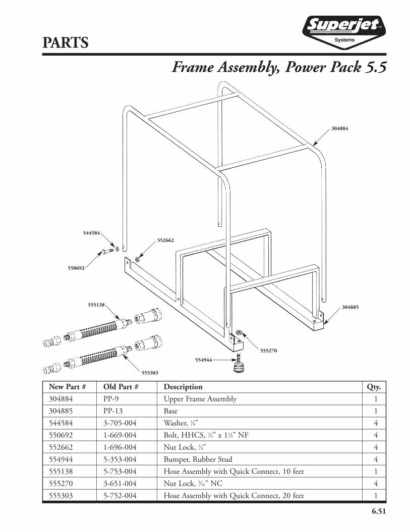
6.51
PARTS
Frame Assembly, Power Pack 5.5
New Part # Old Part # Description Qty.
304884 PP-9 Upper Frame Assembly 1
304885 PP-13 Base 1
544584 3-705-004 Washer, 1⁄4" 4
550692 1-669-004 Bolt, HHCS, 1⁄4" x 11⁄4" NF 4
552662 1-696-004 Nut Lock, 1⁄4" 4
554944 5-353-004 Bumper, Rubber Stud 4
555138 5-753-004 Hose Assembly with Quick Connect, 10 feet 1
555270 3-651-004 Nut Lock, 5⁄16" NC 4
555303 5-752-004 Hose Assembly with Quick Connect, 20 feet 1
555138
554944
555270
552662
304885
550692
304884
555303
544584

6.52
PARTS
New Part # Old Part # Description Qty.
304887 9PP-1 Reservoir 1
304888 9PP-2 Power Pack Frame 1
550194 5-658-004-A Filter Element 1
550722 5-691-004 12MP – 12FP – 12FP Street Tee 1
552747 5-343-004 Quick Connect 3⁄8" Female 1
553066 1-499-004 Filler/Breather Cap Assembly 1
553530 5-658-004 Filter Assembly 1
553896 4-284-004 Magnetic Plug 1
554031 5-688-004 3⁄8" 100R2, #6FS-JIC, #6FS-JIC Hose, 171⁄2" 1
554424 5-399-004 6MP – 6MJ Nipple 1
554616 5-687-004 3⁄4" MP – #10 MJ Adapter 1
554944 5-353-004 Bumper, Rubber Stud 4
555447 5-346-004 6 MP – 6 MP 90° 2
555778 5-403-004 Bushing, 12MP – 6 FP 2
555270 3-651-004 Nut, Lock 5⁄16" NC .4
555447
550194
554031
555447
554944
552747
304887
304888
555270
553530
555778
550020
555778
550722
553896
554616
Reservoir and Frame Assembly, Power Pack 8/9 hp
553066

6.53
PARTS
New Part # Old Part # Description Qty.
551137 911-004 Bolt, HHCS 5⁄16" x 4 4
551572 5-469-004 Fitting, 3⁄8" MP x #8 MJ 1
551651 5-397-004 Coupling, 7⁄16" x 3⁄32" 1
551737 540-004 Bolt, HHCS, 5⁄16" x 1" .4
551985 5-390-004 Pump, Mount 1
552674 5-405-004 Hose, 3⁄8" x 181⁄2" 1
552706 5-391-004 Engine, Honda 5.5 HP with Pull Start 1
552788 5-392-004 Pump 1
552907 113-004 Washer, Lock 5⁄16" 1
554218 4-816-004 Coupling, Insert, Flexible 1
554424 5-399-004 Fitting, 3⁄8" MP x #6 MJ 1
555281 4-944-004 Coupling, Flex, 3⁄4" Bore, 3⁄16" Key 1
555491 5-406-004 1⁄2" 100R1, #8FS-JIC, #8FS-JIC, 90°, 21" 1
555281
551651
554218
551737
552907
551985
552788
552706
555491
551572
551137
552674
554424
Engine/Pump Assembly, Power Pack 5.5 hp
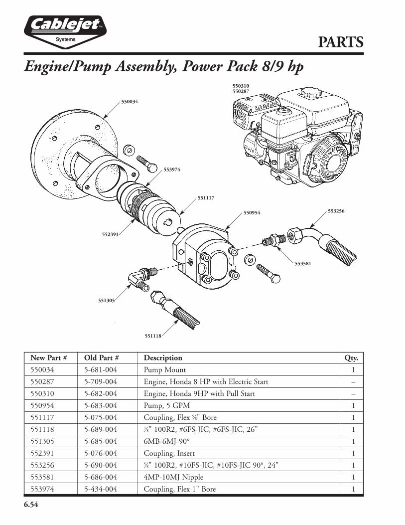
6.54
PARTS
Engine/Pump Assembly, Power Pack 8/9 hp
New Part # Old Part # Description Qty.
550034 5-681-004 Pump Mount 1
550287 5-709-004 Engine, Honda 8 HP with Electric Start –
550310 5-682-004 Engine, Honda 9HP with Pull Start –
550954 5-683-004 Pump, 5 GPM 1
551117 5-075-004 Coupling, Flex 5⁄8" Bore 1
551118 5-689-004 3⁄8" 100R2, #6FS-JIC, #6FS-JIC, 26" 1
551305 5-685-004 6MB-6MJ-90° 1
552391 5-076-004 Coupling, Insert 1
553256 5-690-004 5⁄8" 100R2, #10FS-JIC, #10FS-JIC 90°, 24" 1
553581 5-686-004 4MP-10MJ Nipple 1
553974 5-434-004 Coupling, Flex 1" Bore 1
552391
550034
553974
551117
550954 553256
551118
551305
553581
550310550287

6.55
PARTS
Cable Sealing Inserts and Cable Seals
New Inserts Used Inserts
Cable Cable CableInsert Part # Qty. Insert Part # Seal Part # Qty.
6-9mm 554126 6-9mm 550486 #7 554713
#8.5 551280
#9 552432
#10B 555473
9-11mm 551170 9-11mm 554285 #10 552983
11-12.5mm 552295 11-12.5mm 550183 #12 550251
#13 553371
12.5-14mm 550178 12.5-14mm 552230 #14 550568
14-15.5mm 553870 14-15.5mm 551421 #14 550568
#15 551429
15.5-18mm 551107 15.5-18mm 555302 #16 553761
#17 552892
#19 553274
17.5-22mm 552532 17.5-22mm 552239 #18 551909
#20 553822
#21 550864
#22 552941
22-24mm 553842 22-24mm 553159 #23 550297
#24 552888
24-28mm 553266 24-28mm 551440 #25 554814
#26 552085
#27 554344
28-32mm 554267 28-32mm 554869 #28 553182
#30 550165
32-36mm 551388 32-36mm 552775 #32 551190
#35 554546
#38 551246
Cable Sealing Insert (Red)& Cable Seal
Rope Guide, OuterInsert (Black)
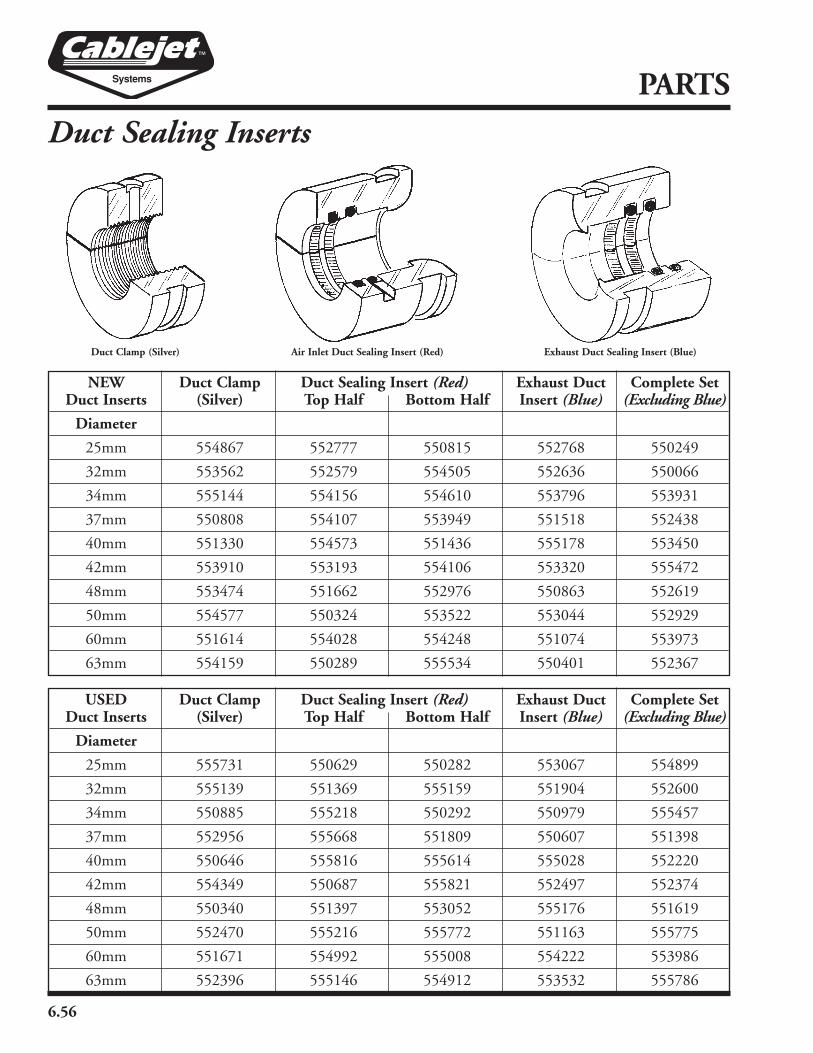
6.56
PARTS
Duct Sealing Inserts
USED Duct Clamp Duct Sealing Insert (Red) Exhaust Duct Complete SetDuct Inserts (Silver) Top Half Bottom Half Insert (Blue) (Excluding Blue)
Diameter
25mm 555731 550629 550282 553067 554899
32mm 555139 551369 555159 551904 552600
34mm 550885 555218 550292 550979 555457
37mm 552956 555668 551809 550607 551398
40mm 550646 555816 555614 555028 552220
42mm 554349 550687 555821 552497 552374
48mm 550340 551397 553052 555176 551619
50mm 552470 555216 555772 551163 555775
60mm 551671 554992 555008 554222 553986
63mm 552396 555146 554912 553532 555786
NEW Duct Clamp Duct Sealing Insert (Red) Exhaust Duct Complete SetDuct Inserts (Silver) Top Half Bottom Half Insert (Blue) (Excluding Blue)
Diameter
25mm 554867 552777 550815 552768 550249
32mm 553562 552579 554505 552636 550066
34mm 555144 554156 554610 553796 553931
37mm 550808 554107 553949 551518 552438
40mm 551330 554573 551436 555178 553450
42mm 553910 553193 554106 553320 555472
48mm 553474 551662 552976 550863 552619
50mm 554577 550324 553522 553044 552929
60mm 551614 554028 554248 551074 553973
63mm 554159 550289 555534 550401 552367
Duct Clamp (Silver) Air Inlet Duct Sealing Insert (Red) Exhaust Duct Sealing Insert (Blue)
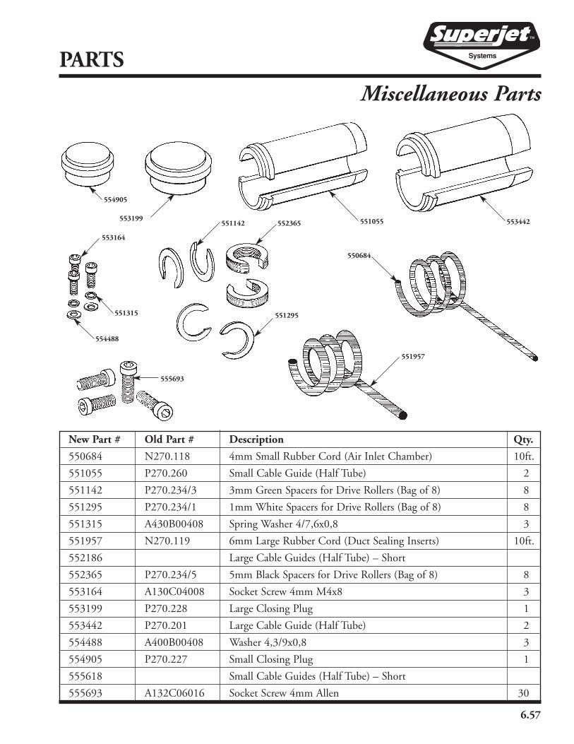
6.57
PARTS
Miscellaneous Parts
New Part # Old Part # Description Qty.
550684 N270.118 4mm Small Rubber Cord (Air Inlet Chamber) 10ft.
551055 P270.260 Small Cable Guide (Half Tube) 2
551142 P270.234/3 3mm Green Spacers for Drive Rollers (Bag of 8) 8
551295 P270.234/1 1mm White Spacers for Drive Rollers (Bag of 8) 8
551315 A430B00408 Spring Washer 4/7,6x0,8 3
551957 N270.119 6mm Large Rubber Cord (Duct Sealing Inserts) 10ft.
552186 Large Cable Guides (Half Tube) – Short
552365 P270.234/5 5mm Black Spacers for Drive Rollers (Bag of 8) 8
553164 A130C04008 Socket Screw 4mm M4x8 3
553199 P270.228 Large Closing Plug 1
553442 P270.201 Large Cable Guide (Half Tube) 2
554488 A400B00408 Washer 4,3/9x0,8 3
554905 P270.227 Small Closing Plug 1
555618 Small Cable Guides (Half Tube) – Short
555693 A132C06016 Socket Screw 4mm Allen 30
553199
550684
551957
551315
554488
553164
552365551142
551295
555693
554905
553442551055

6.58
PARTS
Sonic Head Assembly
A116C06006
P271.028
P271.029
P271.040
P271.027
P271.074
P271.073
P271.026
A116C06008
P271.036
P270.039
P271.034
P271.076
P271.075
P271.033
P271.071
P271.028
A116C06008
A116C06006
P271.035
P271.047
P271.050
P271.045
P271.044
P271.072
P271.046
A116C06008
A116C06006
P271.035
N271.004
N271.003
N271.005
New Part # Old Part # Description Qty.
A116C06006 Set Screw M6x6 Sock Set+cup 6
A116C06008 Set Screw M6x8 Sock Set+cup 6
551960 Hex Socket-wrench 3 1
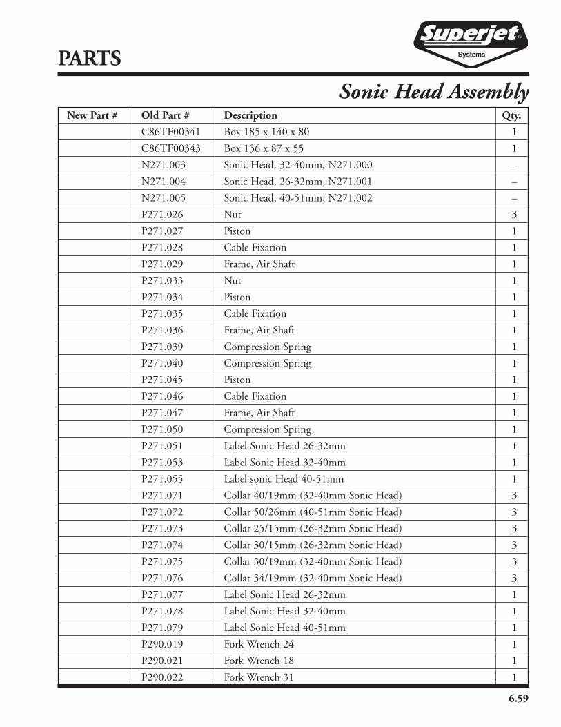
6.59
PARTS
New Part # Old Part # Description Qty.
C86TF00341 Box 185 x 140 x 80 1
C86TF00343 Box 136 x 87 x 55 1
N271.003 Sonic Head, 32-40mm, N271.000 –
N271.004 Sonic Head, 26-32mm, N271.001 –
N271.005 Sonic Head, 40-51mm, N271.002 –
P271.026 Nut 3
P271.027 Piston 1
P271.028 Cable Fixation 1
P271.029 Frame, Air Shaft 1
P271.033 Nut 1
P271.034 Piston 1
P271.035 Cable Fixation 1
P271.036 Frame, Air Shaft 1
P271.039 Compression Spring 1
P271.040 Compression Spring 1
P271.045 Piston 1
P271.046 Cable Fixation 1
P271.047 Frame, Air Shaft 1
P271.050 Compression Spring 1
P271.051 Label Sonic Head 26-32mm 1
P271.053 Label Sonic Head 32-40mm 1
P271.055 Label sonic Head 40-51mm 1
P271.071 Collar 40/19mm (32-40mm Sonic Head) 3
P271.072 Collar 50/26mm (40-51mm Sonic Head) 3
P271.073 Collar 25/15mm (26-32mm Sonic Head) 3
P271.074 Collar 30/15mm (26-32mm Sonic Head) 3
P271.075 Collar 30/19mm (32-40mm Sonic Head) 3
P271.076 Collar 34/19mm (32-40mm Sonic Head) 3
P271.077 Label Sonic Head 26-32mm 1
P271.078 Label Sonic Head 32-40mm 1
P271.079 Label Sonic Head 40-51mm 1
P290.019 Fork Wrench 24 1
P290.021 Fork Wrench 18 1
P290.022 Fork Wrench 31 1
Sonic Head Assembly

6.60
PARTS
Tools and Accessories
550272
Safety Basket
553772
555191
554076
550571
CEC-(size)
552436
552572
554829
551482554640
555610
552549
550187552113
DC-20-(size)
DC-10-(size)
550967

6.61
PARTS
New Part # Old Part # Description Qty.
302230 Cable End Cap, .82" (CEC-82) 1
302231 Cable End Cap, .49" (CEC-49) 1
302232 Cable End Cap, 1.01" (CEC-101) 1
302233 Cable End Cap, .88" (CEC-88) 1
302234 Cable End Cap, .41" (CEC-41) 1
302239 Cable End Cap, .92" (CEC-92) 1
302241 Cable End Cap, .60" (CEC-60) 1
302242 Cable End Cap, .74" (CEC-74) 1
302243 Cable End Cap, .67" (CEC-67) 1
302244 Cable End Cap, .54" (CEC-54) 1
550187 FT-50 Foam Tape – 50 Ft. Roll 1
550272 RSB-1 Replacement Blade for 555191 Cutter 1
550464 Jet Coat Spreaders (JCS-10-150) 1
550571 RSB-2 Replacement Blade for 554076 Cutter 1
550876 AMOWG-10 Air Motor Oil Winter Grade, 16 oz.
550967 6-016-004 ALIS Advanced Longitudinal Interduct Slitter 1
551482 DH-10 Duct Holder Tool 1
552113 CJL-1032 Cablejet Lube Quart 1
552436 5-416-004 9" Rubber Straps 4
552549 AMO-10 Air Motor Oil – 16 Oz. Bottle 1
552572 4-659-004 ALIS Double-Sided Replacement Blade for Slitter 1
553772 CAL-6 6" Digital Calipers 1
554076 RS-2 Duct Cutters for up to 2.37" OD 1
554230 Jet Coat Spreaders (JCS-10-100) 1
554640 5-677-004 Grease Gun 1
554829 4-658-004 Duct Slitter (Longitudinal Cutting) 1
554969 Super Jet Box 1
555191 RS-1 Duct Cutters for up to 1.66" OD 1
555466 Jet Coat Spreaders (JCS-10-125) 1
555610 5-678-004 Grease Replacement Cartridges (2-pack) 1
DC-10-(size) Duct Coupler for 1.06" to 1.97" OD Ducts 1
DC-20-(size) Duct Coupler for 2.24" to 2.45" OD Ducts 1
Safety Basket 1
Tools and Accessories

6.62
PARTS
Tools and Accessories
*550455
551273
554997
552508
*551224
*552711 555784
*552097
552730
551960
551885
553003
552224
552520
554903
553103
553313

6.63
PARTS
New Part # Old Part # Description Qty.
550455 C86JE01010 Circle Clip Pliers 1
551224 P290.003 Spacer Tool 1
551273 C86ES05000 5mm Allen T-Handle 1
551885 C86FH02100 Torx Driver T-10 1
551960 C86EI03000 3mm Allen Wrench 1
552097 6-009-004 4" Flat Head Screwdriver 1
552224 P290.016 Aluminum Accessory/Tool Box 1
552508 C86CS01355 13mm Hex Socket T-Handle 1
552520 N270.116 Air Spray Gun 1
552711 6-002-004 Needle Nose Pliers 1
552730 C86ES04000 4mm Allen T-Handle 1
553003 C86CQ01315 13mm to 17mm Open End Wrench 1
553103 P290.016-05 Foam Tray for Tools and Seals, Top 1
553313 P290.016-03 Foam Tray for Air Gun/Oil, Center 1
554903 P290.016-02 Foam Tray for Inserts, Bottom 1
554997 P290.002 Insert Removal Tool 1
555784 P270.244 Clamp Screw (Sold four per pack) 2
*Cablejet Only
Tools and Accessories
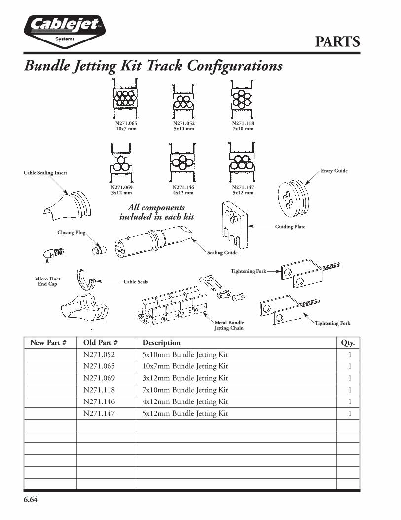
6.64
PARTS
Bundle Jetting Kit Track Configurations
All componentsincluded in each kit
New Part # Old Part # Description Qty.
N271.052 5x10mm Bundle Jetting Kit 1
N271.065 10x7mm Bundle Jetting Kit 1
N271.069 3x12mm Bundle Jetting Kit 1
N271.118 7x10mm Bundle Jetting Kit 1
N271.146 4x12mm Bundle Jetting Kit 1
N271.147 5x12mm Bundle Jetting Kit 1
Entry Guide
Closing PlugGuiding Plate
Tightening Fork
Tightening Fork
Metal BundleJetting Chain
Sealing Guide
Cable Sealing Insert
Micro DuctEnd Cap Cable Seals
N271.06510x7 mm
N271.0525x10 mm
N271.1187x10 mm
N271.0693x12 mm
N271.1464x12 mm
N271.1475x12 mm
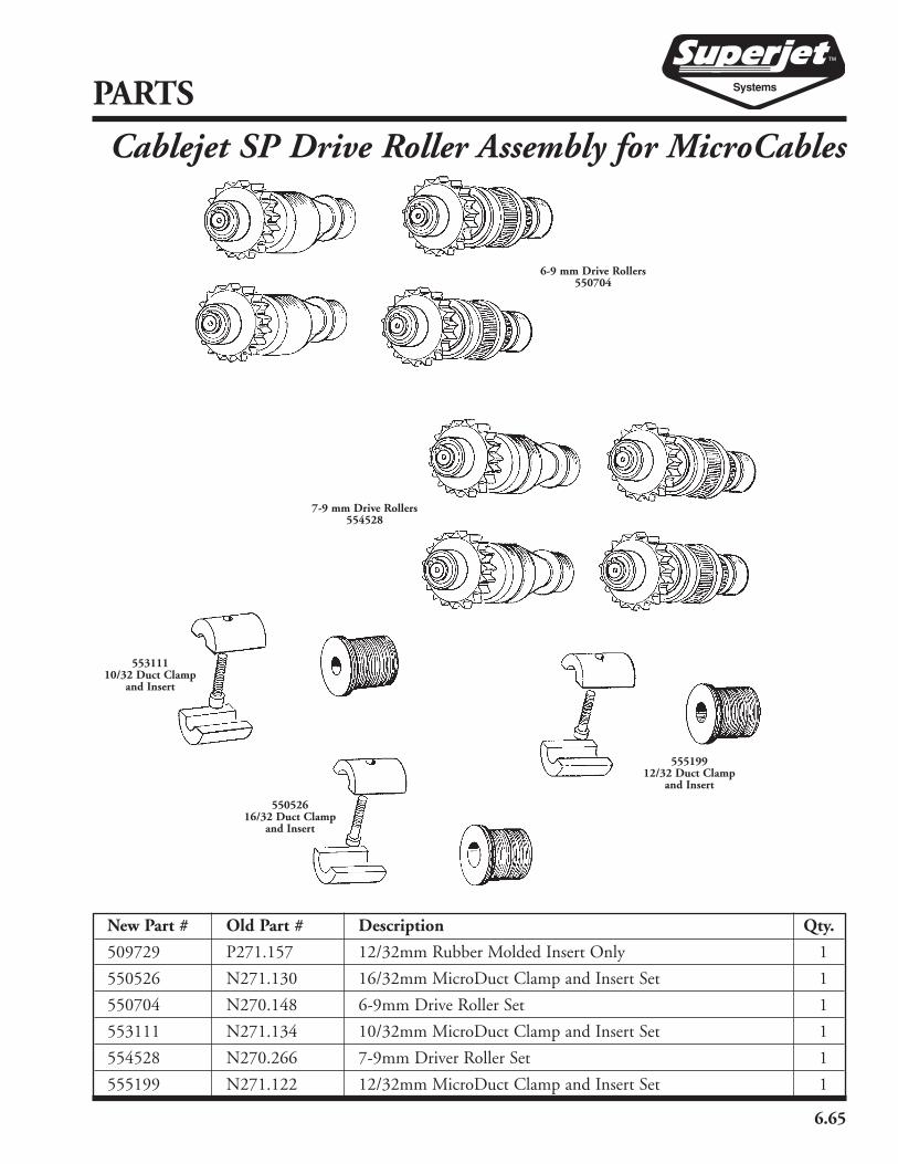
6.65
New Part # Old Part # Description Qty.
509729 P271.157 12/32mm Rubber Molded Insert Only 1
550526 N271.130 16/32mm MicroDuct Clamp and Insert Set 1
550704 N270.148 6-9mm Drive Roller Set 1
553111 N271.134 10/32mm MicroDuct Clamp and Insert Set 1
554528 N270.266 7-9mm Driver Roller Set 1
555199 N271.122 12/32mm MicroDuct Clamp and Insert Set 1
PARTS
Cablejet SP Drive Roller Assembly for MicroCables
6-9 mm Drive Rollers550704
7-9 mm Drive Rollers554528
55519912/32 Duct Clamp
and Insert
55052616/32 Duct Clamp
and Insert
55311110/32 Duct Clamp
and Insert

6.66
PARTS
ASKC-10 Air Support Kit (553109)555313
555277
552633
554287555136
555277
554509
552245
555739
551618
555006
551618
554986
553154550554
550753
552633
553041
555277555099
552305
NA-3
553775
NA-1554953
555605
550421
554780
NA-2 554436
552633
555277 555313
550932

6.67
PARTS
New Part # Old Part # Description Qty.
550421 5-665-004 1⁄2" x 1⁄4" Reducer Bushing 1
550554 BB-12 Test BB #12/10 Microduct (per full box)
550753 6-575-004 BB Catcher (hose with screen) 1
550932 5-340-004 Safety Pin 6
551618 5-339-004 AM12 Coupling 3
552245 6-574-004 Storage Bag 1
552305 5-330-004 1⁄2" Brass Ball Valve 1
552633 5-662-004 1⁄4" Female Quick Connect 21
553041 6-547-004 Pressure Gauge 1
553109 6-576-004 Air Supply Kit, Complete 1
553154 BB-10 Test BB #10/8 Microduct (per full box)
553775 6-545-004 Manifold Block 1
554287 6-554-004 12mm Quick Connect 5
554436 5-667-004 1⁄4" NPT Nipple 5
554509 6-556-004 1⁄4" x 25' Hose 250 PSI 1
554780 4-517-004 1⁄2" Close Nipple 1
554953 5-666-004 3⁄8" x 1⁄4" Male Nipple 1
554986 3-525-004 1⁄2" Female T 1
555006 5-464-004 AM1 Coupling 1
555099 6-549-004 1⁄2" x 3⁄8" Reducer Bushing 1
555136 6-555-004 10mm Quick Connect 5
555277 6-551-004 Foster Plug 16
555313 6-553-004 1⁄4" x 25' Coil Hose 10
555605 6-550-004 1⁄2" NPT Female T 1
555739 6-552-004 1⁄4" Ball Valve 5
NA-1 1⁄2" NPT Plug 1
NA-2 1⁄4" NPT Plug 1
NA-3 1⁄4" NPT Street El 1
ASKC-10 Air Support Kit (553109)
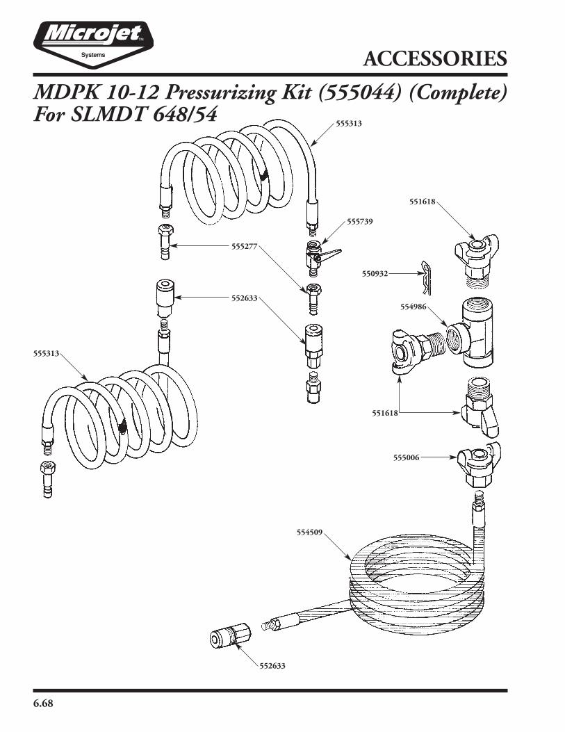
6.68
ACCESSORIES
MDPK 10-12 Pressurizing Kit (555044) (Complete)For SLMDT 648/54
555313
555277
552633
554509
555739
551618
555006
551618
554986
552633
555313
550932
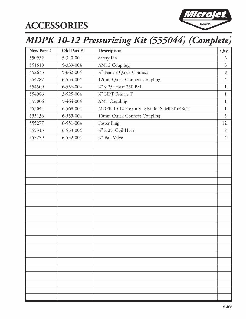
6.69
ACCESSORIES
MDPK 10-12 Pressurizing Kit (555044) (Complete)New Part # Old Part # Description Qty.
550932 5-340-004 Safety Pin 6
551618 5-339-004 AM12 Coupling 3
552633 5-662-004 1⁄4" Female Quick Connect 9
554287 6-554-004 12mm Quick Connect Coupling 4
554509 6-556-004 1⁄4" x 25' Hose 250 PSI 1
554986 3-525-004 1⁄2" NPT Female T 1
555006 5-464-004 AM1 Coupling 1
555044 6-568-004 MDPK-10-12 Pressurizing Kit for SLMDT 648/54 1
555136 6-555-004 10mm Quick Connect Coupling 5
555277 6-551-004 Foster Plug 12
555313 6-553-004 1⁄4" x 25' Coil Hose 8
555739 6-552-004 1⁄4" Ball Valve 4

6.70
ACCESSORIES
Pressurizing Kit Single 10mm (553802)555313
555277
552633
555136
554509
555739
551618
555006
551618
554986
552633
555313
550932
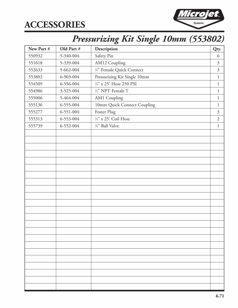
6.71
ACCESSORIES
Pressurizing Kit Single 10mm (553802)New Part # Old Part # Description Qty.
550932 5-340-004 Safety Pin 6
551618 5-339-004 AM12 Coupling 3
552633 5-662-004 1⁄4" Female Quick Connect 3
553802 6-903-004 Pressurizing Kit Single 10mm 1
554509 6-556-004 1⁄4" x 25' Hose 250 PSI 1
554986 3-525-004 1⁄2" NPT Female T 1
555006 5-464-004 AM1 Coupling 1
555136 6-555-004 10mm Quick Connect Coupling 1
555277 6-551-004 Foster Plug 3
555313 6-553-004 1⁄4" x 25' Coil Hose 2
555739 6-552-004 1⁄4" Ball Valve 1

Pressurizing Kit Single 12mm (553802)555313
555277
552633
554287
554509
555739
551618
555006
551618
554986
552633
555313
550932
6.72
ACCESSORIES

6.73
ACCESSORIES
Pressurizing Kit Single 12mm (553802)New Part # Old Part # Description Qty.
550932 5-340-004 Safety Pin 6
551618 5-339-004 AM12 Coupling 3
552633 5-662-004 1⁄4" Female Quick Connect 3
553825 6-904-004 Pressurizing Kit Single 12mm 1
554287 6-554-004 12mm Quick Connect Coupling 1
554509 6-556-004 1⁄4" x 25' Hose 250 PSI 1
554986 3-525-004 1⁄2" NPT Female T 1
555006 5-464-004 AM1 Coupling 1
555277 6-551-004 Foster Plug 3
555313 6-553-004 1⁄4" x 25' Coil Hose 2
555739 6-552-004 1⁄4" Ball Valve 1

555313
555277
551804
550426
554509
555739
551618
555006
551618
554986
552633
555313
550932
6.74
ACCESSORIES
Pressurizing Kit Single 16mm (555076)
552633

6.75
ACCESSORIES
Pressurizing Kit Single 16mm (555076)New Part # Old Part # Description Qty.
550426 6-645-004 16mm Quick Connect Coupling 1
550932 5-340-004 Safety Pin 6
551618 5-339-004 AM12 Coupling 3
551804 6-647-004 3⁄8" Female Quick Connect 1
552633 5-662-004 1⁄4" Female Quick Connect 3
554509 6-556-004 1⁄4" x 25' Hose 250 PSI 1
554986 3-525-004 1⁄2" NPT Female T 1
555006 5-464-004 AM1 Coupling 1
555017 6-646-004 Adapt All Adapter (not pictured) 1
555076 6-587-004 Pressurizing Kit Single 16mm 1
555277 6-551-004 Foster Plug 3
555313 6-553-004 1⁄4" x 25' Coil Hose 2
555739 6-552-004 1⁄4" Ball Valve 1

6.76
New Part # Old Part # Description Qty.
552633 5-662-004 1⁄4" Female Quick Connect 2
555074 6-534-004 ASM Coiled Pressure Hose – 10mm 1
555136 6-555-004 10mm Quick Connect Coupling 1
555277 6-551-004 Foster Plug 3
555313 6-553-004 1⁄4" x 25' Coil Hose 2
555739 6-552-004 1⁄4" Ball Valve 1
ACCESSORIES
ASM Coiled Pressure Hose 10mm (555074)
555313
555277
555739
555136
552633
555313
555277
552633

6.77
New Part # Old Part # Description Qty.
552633 5-662-004 1⁄4" Female Quick Connect 2
554287 6-554-004 12mm Quick Connect Coupling 1
554531 6-537-004 ASM Coiled Pressure Hose – 12mm 1
555277 6-551-004 Foster Plug 3
555313 6-553-004 1⁄4" x 25' Coil Hose 2
555739 6-552-004 1⁄4" Ball Valve 1
ASM Coiled Pressure Hose 12mm (554531)
ACCESSORIES
555313
555277
555739
554287
552633
555313
555277
552633

6.78
New Part # Old Part # Description Qty.
550426 6-645-004 16mm Quick Connect Coupling 1
550559 6-935-004 ASM Coiled Pressure Hose – 16mm 1
551804 6-647-004 3⁄8" Female Quick Connect 1
555277 6-551-004 Foster Plug 3
552633 5-662-004 1⁄4" Female Quick Connect 2
555017 6-646-004 Adapt All Adapter (not pictured) 1
555313 6-553-004 1⁄4" x 25' Coil Hose 2
555739 6-552-004 1⁄4" Ball Valve 1
ACCESSORIES
ASM Coiled Pressure Hose 16mm (550559)
555313
555277
555739
550426
551804
555313
555277
552633

6.79
ACCESSORIES
New Part # Old Part # Description Qty.
550554 BB-12 Test BB #12/10 Microduct with Box (per full box) 1
550685 6-569-004 MDP-10-12 Proofing Kit 1
550753 6-575-004 BB Catcher (hose with screen) 1
552113 CJL-1032 Cablejet Lube (1 quart) 9
553527 6-479-004 Micro Duct Cutter 1
554233 6-500-004 12mm Micro Spreaders (bag of 20) 10
554641 6-498-004 Microjet Lube (8 oz) 3
552113
554233
553527
550753
MDP-10-12 Proofing Kit (550685)
550554
554641

6.80
New Part # Old Part # Description Qty.
302229 DEC-12 12mm Microduct End Caps 10
550196 6-576-004 QDPK-10-12mm Duct Preparation Kit 1
550730 6-502-004 Microduct Ring Cutter 1
551853 6-492-004 12mm End Stops 50
551996 6-482-004 12mm Straight Couplers 100
553527 6-479-004 Microduct Cutter 1
554829 4-658-004 Duct Slitter 1
555191 RS-1 Duct Cutter (up to 1.66) 1
QDPK 10-12mm Duct Preparation Kit (550196)
555191
554829
553527
550730
302229551853
551996
ACCESSORIES

6.81
Part # Description Qty.
Duct Sealing Insert Complete Sets
550249 25mm duct sealing insert (excludes exhaust-blue)
550066 32mm duct sealing insert (excludes exhaust-blue)
553931 34mm duct sealing insert (excludes exhaust-blue)
552438 37mm duct sealing insert (excludes exhaust-blue)
553450 40mm duct sealing insert (excludes exhaust-blue)
555472 42mm duct sealing insert (excludes exhaust-blue)
552619 48mm duct sealing insert (excludes exhaust-blue)
552929 50mm duct sealing insert (excludes exhaust-blue)
553973 60mm duct sealing insert (excludes exhaust-blue)
552367 63mm duct sealing insert (excludes exhaust-blue)
Cable Sealing Inserts
554126 6-9mm set of Cable Sealing Inserts
551170 9-11mm set of Cable Sealing Inserts
552295 11-12.5mm set of Cable Sealing Inserts
550178 12.5-14mm set of Cable Sealing Inserts
553870 14-15.5mm set of Cable Sealing Inserts
551107 15.5-18mm set of Cable Sealing Inserts
552532 17.5-22mm set of Cable Sealing Inserts
553842 22-24mm set of Cable Sealing Inserts
553266 24-28mm set of Cable Sealing Inserts
554267 28-32mm set of Cable Sealing Inserts
551388 32-36mm set of Cable Sealing Inserts
Cable Seals
554713 7mm cable seals (20-half seals)
551280 8.5mm cable seals (20-half seals)
552432 9mm cable seals (20-half seals)
555473 10Bmm cable seals (20-half seals)
552983 10mm cable seals (20-half seals)
550251 12mm cable seals (20-half seals)
553371 13mm cable seals (20-half seals)
550568 14mm cable seals (20-half seals)
PARTS
Tools & Accessories

6.82
PARTS
Tools & AccessoriesPart # Description Qty.
Cable Seals (continued)
551429 15mm cable seals (20-half seals)
553761 16mm cable seals (20-half seals)
552892 17mm cable seals (20-half seals)
553274 18mm cable seals (20-half seals)
551909 19mm cable seals (20-half seals)
553822 20mm cable seals (20-half seals)
550864 21mm cable seals (20-half seals)
552941 22mm cable seals (20-half seals)
550297 23mm cable seals (20-half seals)
552888 24mm cable seals (20-half seals)
554814 25mm cable seals (20-half seals)
552085 26mm cable seals (20-half seals)
554344 27mm cable seals (20-half seals)
553182 28mm cable seals (20-half seals)
550165 30mm cable seals (20-half seals)
551190 32mm cable seals (20-half seals)
554546 35mm cable seals (8-half seals)
551246 38mm cable seals (8-half seals)
Duct Sealing Insert Individual Parts
554867 25mm half duct clamp
552777 25mm bottom half duct sealing insert (red)
550815 25mm top half duct sealing insert (red)
552768 25mm half duct sealing insert (blue)
553562 32mm half duct clamp
552579 32mm bottom half duct sealing insert (red)
554505 32mm top half duct sealing insert (red)
552636 32mm half duct sealing insert (blue)
555144 34mm half duct clamp
554156 34mm bottom half duct sealing insert (red)
554610 34mm top half duct sealing insert (red)
553796 34mm half duct sealing insert (blue)
550808 37mm half duct clamp

6.83
PARTS
Tools & AccessoriesPart # Description Qty.
Duct Sealing Insert Individual Parts (continued)
554107 37mm bottom half duct sealing insert (red)
553949 37mm top half duct sealing insert (red)
551518 37mm half duct sealing insert (blue)
551330 40mm half duct clamp
554573 40mm bottom half duct sealing insert (red)
551436 40mm top half duct sealing insert (red)
555178 40mm half duct sealing insert (blue)
553910 42mm half duct clamp
553193 42mm bottom half duct sealing insert (red)
554106 42mm top half duct sealing insert (red)
553320 42mm half duct sealing insert (blue)
553474 48mm half duct clamp
551662 48mm bottom half duct sealing insert (red)
552976 48mm top half duct sealing insert (red)
550863 48mm half duct sealing insert (blue)
554577 50mm half duct clamp
550324 50mm bottom half duct sealing insert (red)
553522 50mm top half duct sealing insert (red)
553044 50mm half duct sealing insert (blue)
551614 60mm half duct clamp
554028 60mm bottom half duct sealing insert (red)
554248 60mm top half duct sealing insert (red)
551074 60mm half duct sealing insert (blue)
554159 63mm half duct clamp
550289 63mm bottom half duct sealing insert (red)
555534 63mm top half duct sealing insert (red)
550401 63mm half duct sealing insert (blue)
Superjet & CableJet Standard Tools & Accessories
550684 4mm Small Rubber Cord (for air inlet chamber)
551957 6mm Large Rubber Cord (for duct sealing inserts)
551960 3mm Allen Wrench
552730 4mm Allen t-handle

6.84
PARTS
Tools & AccessoriesPart # Description Qty.
Superjet & CableJet Standard Tools & Accessories (continued)
551273 5mm Allen t-handle
553003 17-13mm open end wrench
552508 13mm Hexagon Socket t-handle
551885 T-10 Screw Driver
554997 Insert Removal Tool
551224 Spacer Tool
552029 Flat head screwdriver
552097 Needle nose pliers
554905 Small Closing plug
553199 Large Closing plug
555618 Small Cable Guide (half tube)-short
552186 Large Cable Guide (half tube)-short
551055 Small Cable Guide (half tube)-long
553442 Large Cable Guide (half tube)-long
551295 1mm White Spacers for Drive Rollers (per spacer)
551142 3mm Green Spacers for Drive Rollers (per spacer)
552365 5mm Black Spacers for Drive Rollers (per spacer)
552520 Air Spray Gun
552549 Air motor oil (for Pneumatic Superjet)
550876 Air motor oil winter grade(for Pneumatic Superjet)
552224 Aluminum Box (Accessories)
553103 Foam Tray for Tools & Seals (top)
553313 Foam Tray for Air Gun & Oil (middle)
554903 Foam Tray for Inserts (bottom)
552436 9" Rubber Straps
555610 White lithium grease for chain
553375 Large Rubber Gromets for compressor hose
555693 4mm Hex Head Screw for Inserts
550462 Clamp Nut (with purchased unit)
555784 Clamp Screws (sold 4 per pack)

6.85
PARTS
Tools & AccessoriesPart # Description Qty.
Sonic Heads
554133 Sonic Head 26-32mm
555545 Sonic Head 32-40mm
553865 Sonic Head 40-51mm
Sherman & Reilly Accessories
554829 Longitudinal duct slitting tool (Petrocom)
552572 Replacement blades for slitting tool
550967 ALIS Tool
555191 Reed Duct Cutters for up to 1.66" OD
554076 Reed Duct Cutters for up to 2.37" OD
550272 Replacement Blade for RS-1 duct cutter
550571 Replacement Blade for RS-2 duct cutter
555610 White Lithium Grease for drive chain (2 Pack)
552549 Air Motor Oil (16 oz. Bottle)
550876 Air Motor Oil Winter Grade (16 oz. Bottle)
551482 Duct holder for use in installing DC-10 couplers
550187 50ft. roll of foam sealing material for DC-10 couplers
302234 .41" Cable end cap
302231 .49" Cable end cap
302244 .54" Cable end cap
302241 .60" Cable end cap
302243 .67" Cable end cap
302242 .74" Cable end cap
302230 .82" Cable end cap
302233 .88" Cable end cap
302239 .92" Cable end cap
302232 1.01" Cable end cap
552113 Cablejet Lube (1 qt.)
553772 6" Digital Calipers for measuring duct & cable
554230 JetCoat Spreaders for .75” - 1.25” duct (bag of 10)
555466 JetCoat Spreaders for 1.25” - 1.50” duct (bag of 10)
550464 JetCoat Spreaders for 1.50” - 2.00” duct (bag of 10)
554640 Grease Gun

6.86
PARTS
Tools & AccessoriesPart # Description Qty.
Sherman & Reilly DC-10 Couplers
700991 DC-10-1.06 (minimum of 20 couplers)
700959 DC-10-1.062
700794 DC-10-1.14
700027 DC-10-1.19
700954 DC-10-1.23
700557 DC-10-1.28
554191 DC-10-1.26
700999 DC-10-1.30
700990 DC-10-1.33
701070 DC-10-1.34
700138 DC-10-1.35
700676 DC-10-1.38
700210 DC-10-1.40
700635 DC-10-1.42
701030 DC-10-1.45
701118 DC-10-1.47
700695 DC-10-1.50
701079 DC-10-1.52
700773 DC-10-1.55
700063 DC-10-1.57
701032 DC-10-1.61
701073 DC-10-1.64
701095 DC-10-1.66
701026 DC-10-1.68
700109 DC-10-1.70
700250 DC-10-1.76
700443 DC-10-1.80
700753 DC-10-1.82
700297 DC-10-1.88
701013 DC-10-1.90
700282 DC-10-1.94
701128 DC-10-1.97
700216 DC-10-2.10
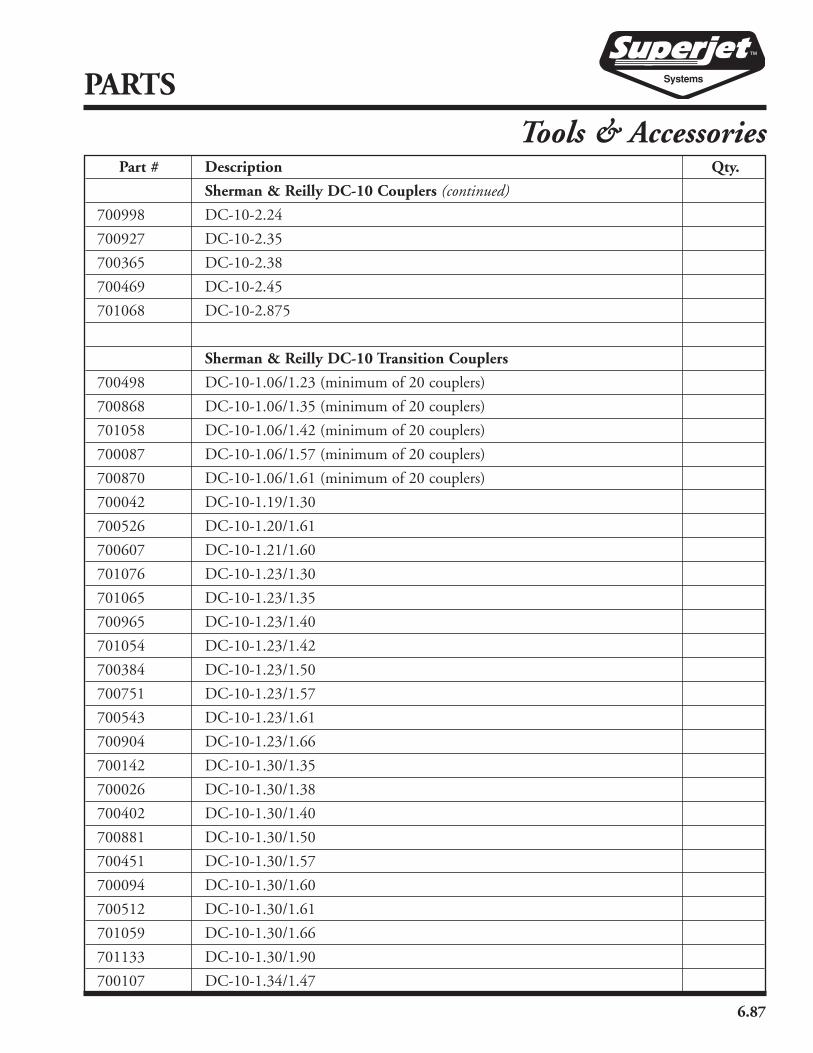
6.87
PARTS
Tools & AccessoriesPart # Description Qty.
Sherman & Reilly DC-10 Couplers (continued)
700998 DC-10-2.24
700927 DC-10-2.35
700365 DC-10-2.38
700469 DC-10-2.45
701068 DC-10-2.875
Sherman & Reilly DC-10 Transition Couplers
700498 DC-10-1.06/1.23 (minimum of 20 couplers)
700868 DC-10-1.06/1.35 (minimum of 20 couplers)
701058 DC-10-1.06/1.42 (minimum of 20 couplers)
700087 DC-10-1.06/1.57 (minimum of 20 couplers)
700870 DC-10-1.06/1.61 (minimum of 20 couplers)
700042 DC-10-1.19/1.30
700526 DC-10-1.20/1.61
700607 DC-10-1.21/1.60
701076 DC-10-1.23/1.30
701065 DC-10-1.23/1.35
700965 DC-10-1.23/1.40
701054 DC-10-1.23/1.42
700384 DC-10-1.23/1.50
700751 DC-10-1.23/1.57
700543 DC-10-1.23/1.61
700904 DC-10-1.23/1.66
700142 DC-10-1.30/1.35
700026 DC-10-1.30/1.38
700402 DC-10-1.30/1.40
700881 DC-10-1.30/1.50
700451 DC-10-1.30/1.57
700094 DC-10-1.30/1.60
700512 DC-10-1.30/1.61
701059 DC-10-1.30/1.66
701133 DC-10-1.30/1.90
700107 DC-10-1.34/1.47

6.88
PARTS
Tools & AccessoriesPart # Description Qty.
Sherman & Reilly DC-10 Transition Couplers (continued)
700483 DC-10-1.35/1.40
700719 DC-10-1.35/1.47
700015 DC-10-1.35/1.52
700610 DC-10-1.35/1.57
700231 DC-10-1.35/1.61
700948 DC-10-1.35/1.66
700082 DC-10-1.40/1.47
700417 DC-10-1.40/1.50
701075 DC-10-1.40/1.61
700309 DC-10-1.40/1.66
701091 DC-10-1.45/1.66
700918 DC-10-1.47/1.57
700906 DC-10-1.47/1.64
700887 DC-10-1.47/1.66
700043 DC-10-1.47/1.70
700134 DC-10-1.50/1.66
701137 DC-10-1.50/1.70
700162 DC-10-1.50/1.76
700531 DC-10-1.50/1.80
700081 DC-10-1.51/1.66
700175 DC-10-1.52/1.61
700564 DC-10-1.52/1.66
700534 DC-10-1.52/1.90
700511 DC-10-1.52/2.38
700129 DC-10-1.56/1.70
700530 DC-10-1.57/1.61
700281 DC-10-1.57/1.66
700910 DC-10-1.57/2.45
700164 DC-10-1.60/1.66
701042 DC-10-1.61/1.66
700525 DC-10-1.61/1.88
700734 DC-10-1.61/1.90
700490 DC-10-1.61/2.35

6.89
Part # Description Qty.
Sherman & Reilly DC-10 Transition Couplers (continued)
700222 DC-10-1.64/1.89
700006 DC-10-1.66/1.88
701124 DC-10-1.66/1.90
700688 DC-10-1.66/1.97
700331 DC-10-1.66/2.35
700712 DC-10-1.66/2.38
700165 DC-10-1.66/2.45
700177 DC-10-1.88/2.35
700540 DC-10-1.88/2.38
700726 DC-10-1.90/1.97
700229 DC-10-1.90/2.35
700193 DC-10-1.90/2.38
700074 DC-10-2.35/2.64
700510 DC-10-2.35/3.53
Sherman & Reilly Push-2-Connects
553259 Push-2-Connect 1.58
554019 Push-2-Connect 1.66
551756 Push-2-Connect Transition 1.58/1.66
Sherman & Reilly MicroJet Accessories
554641 MicroJet Lube (8 oz. bottle)
550044 7mm MicroDuct Spreaders
551507 10mm MicroDuct Spreaders
554233 12mm MicroDuct Spreaders
550654 7mm MicroDuct End Caps
550831 10mm MicroDuct End Caps
552350 12mm MicroDuct End Caps
551726 16mm MicroDuct End Caps
553527 MicroDuct Cutters
550730 MicroDuct Ring Cutters
Replacement Blades for Cutter
552521 MicroDuct Coupler Quick Release Tool
PARTS
Tools & Accessories

6.90
PARTS
Tools & AccessoriesPart # Description Qty.
Sherman & Reilly MicroJet Couplers & End Stops
552764 5mm MicroDuct Airtight Coupler
550588 7mm MicroDuct Airtight Coupler
552735 8mm MicroDuct Airtight Coupler
555373 8.5mm MicroDuct Airtight Coupler
552836 10mm MicroDuct Airtight Coupler
551996 12mm MicroDuct Airtight Coupler
552015 12.7mm MicroDuct Airtight Coupler
554057 14mm MicroDuct Airtight Coupler
555638 16mm MicroDuct Airtight Coupler
550999 5mm-7mm MicroDuct Transition Airtight Coupler
554998 5mm-8mm MicroDuct Transition Airtight Coupler
554597 7mm-10mm MicroDuct Transition Airtight Coupler
553497 10mm-12mm MicroDuct Transition Airtight Coupler
553478 12mm-12.7mm MicroDuct Transition Airtight Coupler
552346 7mm MicroDuct End Stops
551020 8mm MicroDuct End Stops
552585 10mm MicroDuct End Stops
551853 12mm MicroDuct End Stops
553421 12.7mm MicroDuct End Stops
553061 14mm MicroDuct End Stops
Y-Branch Connectors
555564 40mm-40mm-25mm Y-Branch Connectors
550378 42mm-42mm-42mm Y-Branch Connectors
551417 50mm-50mm-25mm Y-Branch Connectors
551700 50mm-50mm-50mm Y-Branch Connectors
554719 60mm-60mm-60mm Y-Branch Connectors
553321 50mm-32mm Y-Port Reducers
550088 60mm-40mm Y-Port Reducers


SHERMAN & REILLY, INC.P.O. Box 11267 • 400 West 33rd StreetChattanooga, TN 37401 USAPhone 423•756•5300Fax No. 423•756•2948Toll-free 800•251•7780Web Site www.sherman-reilly.com
Manual No. SuperjetCablejetMicrojet Printed in the U.S.A. by Rogers Printing Solutions