Embed Size (px)
DESCRIPTION
transmisor net safety
Citation preview

Part Number: MAN-0076 Rev Aprl
2008
MILLENNIUM II
Multi-Channel Transmitter
User Manual
Single or Dual Channel
Part Number: MAN-0076 Rev 05
December 07, 2012

2
MAN-0076 Rev 05 Millennium II
December 07, 2012
Net Safety Monitoring Inc
IMPORTANT INFORMATION This manual is for informational purposes only. Although every effort has been made to ensure the correctness of the
information, technical inaccuracies may occur and periodic changes may be made without notice. Net Safety
Monitoring Inc., assumes no responsibility for any errors contained within this manual.
If the products or procedures are used for purposes other than as described in the manual, without receiving prior
confirmation of validity or suitability, Net Safety Monitoring Inc., does not guarantee the results and assumes no
obligation or liability. No part of this manual may be copied, disseminated or distributed without the express written
consent of Net Safety Monitoring Inc.
Net Safety Monitoring Inc., products are carefully designed and manufactured from high quality components and can
be expected to provide many years of trouble free service. Each product is thoroughly tested, inspected and calibrated
prior to shipment. Failures can occur which are beyond the control of the manufacturer. Failures can be minimized by
adhering to the operating and maintenance instructions herein. Where the absolute greatest of reliability is required,
redundancy should be designed into the system.
WARRANTY Net Safety Monitoring Inc warrants its electronic assemblies against defective parts and workmanship for a period of
36 months from date of purchase. No other warranties or liability, expressed or implied, will be honored by Net Safety
Monitoring Inc. Contact Net Safety Monitoring Inc. or an authorized representative for details.
We welcome your input at Net Safety Monitoring. If you have any comments please contact us at the phone/ address
below or visit our web site and complete our on-line customer survey: www.net-safety.com/
If further language translation for this manual is required please contact:
CONTACT INFORMATION Net Safety Monitoring Inc Direct: (403) 219-0688
Corporate Headquarters Facsimile: (403) 219-0694
2721 Hopewell Place NE E-mail: [email protected]
Calgary, AB Canada T1Y 7J7 Web-site: www.net-safety.com/
3
MAN-0076 Rev 05 Millennium II
December 07, 2012
Net Safety Monitoring Inc
TABLE OF CONTENTS
IMPORTANT INFORMATION ...................................................................................................................................................... 2
WARRANTY ...................................................................................................................................................................................... 2
CONTACT INFORMATION ........................................................................................................................................................... 2
INTRODUCTION .............................................................................................................................................................................. 5
THE PRODUCT .............................................................................................................................................................................. 5 TRANSMITTER/CONTROLLER.................................................................................................................................................. 5 THE MANUAL ............................................................................................................................................................................... 5
Special conditions of use: ........................................................................................................................................................... 5 Housing Dimensions ................................................................................................................................................................... 6
SECTION 1: INSTALLATION ....................................................................................................................................................... 7
1.1 UNPACK ..................................................................................................................................................................................... 7 1.2 MOUNTING ................................................................................................................................................................................. 7
1.2.1 Transmitter Orientation Option ......................................................................................................................................... 7 1.2.2 Transmitter electronics module and Relay options ........................................................................................................... 8 1.2.3 Rotating electronics module relative to enclosure and conduit entries ............................................................................. 9
SECTION 2: WIRING AND INSTALLATION .......................................................................................................................... 10
2.1 FIELD INSTALLATION ............................................................................................................................................................... 10 Guidelines ................................................................................................................................................................................. 10 2.1.1 Seals ................................................................................................................................................................................. 10 Guidelines ................................................................................................................................................................................. 10 2.1.2 Cable choice and guidelines ............................................................................................................................................ 11 2.1.3 Analog output, isolated supply, non-isolated supply and jumper configuration ............................................................. 13 2.1.4 Remotely mounted sensors jumper configuration ............................................................................................................ 14 2.1.5 Sensor and Transmitter terminals ................................................................................................................................... 15 2.1.6 Remote Reset ................................................................................................................................................................... 16 2.1.7 Sensor Separation/ Remote mounting of sensor .............................................................................................................. 16 2.1.8 Wiring drawings .............................................................................................................................................................. 17 2.1.9 Installation Checklist ....................................................................................................................................................... 19
SECTION 3: TRANSMITTER AND FACEPLATE DESCRIPTION....................................................................................... 20
3.1 TRANSMITTER POWER UP ........................................................................................................................................................ 20 3.2 DISPLAY ................................................................................................................................................................................... 20 3.3 STATUS LED ............................................................................................................................................................................ 21 3.4 CURRENT LOOP MEASUREMENT (TEST JACKS) ......................................................................................................................... 21 3.5 MENU BUTTONS AND ACCESS ................................................................................................................................................... 21
3.5.1 Intrusive Access ............................................................................................................................................................... 21 3.5.2 Non-Intrusive Access/Magnetic Reed switch Access ....................................................................................................... 21
SECTION 4: OPERATION ........................................................................................................................................................... 22
4.1 MENU OPTIONS ......................................................................................................................................................................... 22 4.2 NAVIGATING MAIN MENU ......................................................................................................................................................... 22
4.2.1 Full calibration (Normal calibration) procedure ............................................................................................................ 24 4.2.2 (Cont’d) Zero calibration option ..................................................................................................................................... 25 4.2.3 Enable / Disable channels ............................................................................................................................................... 27 4.2.4 Viewing and setting alarm levels (points) ........................................................................................................................ 27 4.2.5 Setting Relay options ....................................................................................................................................................... 28 4.2.6 Relay Assignment ............................................................................................................................................................. 28 4.2.7 Relay Alarm Mode setting (for Oxygen sensors only) ..................................................................................................... 30
4
MAN-0076 Rev 05 Millennium II
December 07, 2012
Net Safety Monitoring Inc
4.2.8 Select Display Language ................................................................................................................................................. 30 4.2.9 MODBUS Setup ............................................................................................................................................................... 30 4.3.0 Setup Current Date .......................................................................................................................................................... 31 4.3.1 Setup Current Time .......................................................................................................................................................... 31 4.3.2 View Event Log ................................................................................................................................................................ 32 4.3.3 Manual Reset ................................................................................................................................................................... 33 4.3.4 Self Test Relay ................................................................................................................................................................. 33 4.3.5 Sensor Upper Limit (Range) ............................................................................................................................................ 33 4.3.6 Select Gas Type ............................................................................................................................................................... 34 4.3.7 Calibration gas value ...................................................................................................................................................... 34 4.3.8 Serial Number & Firmware Version ............................................................................................................................... 34
SECTION 5: MONITORING AND OUTPUTS .......................................................................................................................... 35
5.1FAULT MONITORING .................................................................................................................................................................. 35 5.2 RELAYS .................................................................................................................................................................................... 35 5.3 ANALOG 4-20MA ..................................................................................................................................................................... 35
Sensor Status Registers, Transmitter Status LED, Current output and Meaning ..................................................................... 36 5.4 RS-485 MODBUS RTU ............................................................................................................................................................. 37 5.5 HART COMMUNICATION ......................................................................................................................................................... 39
SECTION 6: MAINTAINING ...................................................................................................................................................... 40
6.1 PERIODIC RESPONSE CHECK ...................................................................................................................................................... 40 6.2 TROUBLESHOOTING.................................................................................................................................................................. 40 6.3 STORAGE .................................................................................................................................................................................. 41 6.4 SPARE PARTS /ACCESSORIES .................................................................................................................................................... 41 6.5 HOW TO RETURN EQUIPMENT .................................................................................................................................................. 42
APPENDIX ....................................................................................................................................................................................... 43
APPENDIX A: ELECTROSTATIC SENSITIVE DEVICE (ESD) ............................................................................................. 43
APPENDIX B: RESISTANCE TABLE ......................................................................................................................................... 44
APPENDIX C: MILLENNIUM II TRANSMITTER SPECIFICATIONS ................................................................................ 45
5
MAN-0076 Rev 05 Millennium II
December 07, 2012
Net Safety Monitoring Inc
INTRODUCTION Building on the outstanding legacy of the Millennium Series, Net Safety’s latest innovation in this line of continuously
evolving industrial transmitters and sensors, the Millennium II, pushes the boundaries of what you can expect from
your detection system. Combined with state of the art “Smart” sensors, users will receive a detection system which is
both versatile and reliable for fast, accurate and continuous monitoring of gases in extreme environments.
THE PRODUCT
TRANSMITTER/CONTROLLER A Millennium II gas detection system is composed of a field mounted transmitter\controller and Millennium II
series sensors which may be integrally mounted to the controller or remotely mounted as far as 2000 feet away.
The transmitter is certified for use in hazardous locations and is available as a single or dual sensor system. All
operator controls including configuration and calibration can be accessed without opening the enclosure by using other
communication devices and the attached magnet to actuate reed switches. If the area is non-hazardous and the
enclosure (housing) is open then the operator may choose to use push-button switches and analog output test jacks on
the face of the electronics module. Available outputs are: conventional 0.0 to 20mA analog, Analog/HART,
electromechanical relays, solid-state relays or Modbus RTU digital.
A dual channel transmitter is available with "peak picking" functionality where there is only one analog output and this
analog output follows the signal from the sensor that is responding to the highest gas concentration. This is useful in
conserving analog input capacity on connected user equipment.
THE MANUAL This manual has been designed to guide users through each procedure, ensuring that transmitters and sensors are
configured, operated and maintained properly. Guidelines and warnings are included to ensure safe and proper
functioning of the equipment. The manual gives the overall operational and functional features of transmitters
with sensors and may not have sensor specific information. Refer to sensor manuals for information specific to
each sensor including detailed calibration instructions. If you encounter any problems, see the troubleshooting
section of this manual or contact factory.
Special conditions of use:
M2a-b-c, Millennium II Transmitter with enclosure:
1. In order to maintain the performance of the system, the sensor to which this instrument is connected
shall also comply with the requirements of EN 61779-1 and EN 61779-4
TX-M2a-b, Millennium II Transmitter Electronics module only (w/o enclosure):
1. If the Millennium II Transmitter is installed as Category 3 equipment, then it shall be installed in an
Enclosure which maintains an ingress protection rating of IP54 and meets the enclosure requirements
of EN 60079-0.
2. In order to maintain the performance of the system, the sensor to which the instrument is connected
shall also comply with requirements of EN 61779-1 and EN 61779-4
6
MAN-0076 Rev 05 Millennium II
December 07, 2012
Net Safety Monitoring Inc
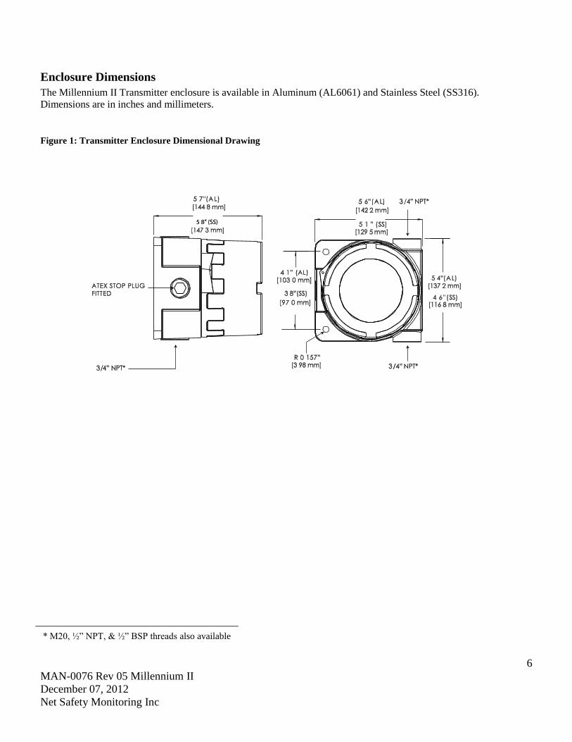
Enclosure Dimensions
The Millennium II Transmitter enclosure is available in Aluminum (AL6061) and Stainless Steel (SS316).
Dimensions are in inches and millimeters.
Figure 1: Transmitter Enclosure Dimensional Drawing
* M20, ½” NPT, & ½” BSP threads also available
7
MAN-0076 Rev 05 Millennium II
December 07, 2012
Net Safety Monitoring Inc
SECTION 1: Installation
1.1 Unpack
Carefully remove all components from the packaging and check them against the enclosed packing list. Inspect all
components for obvious damage such as broken or loose parts. If you find any components missing or damaged, notify
the representative or Net Safety Monitoring, immediately.
1.2 Mounting
Ensure transmitter and sensor are securely mounted, taking into consideration all requirements. Sensors may be
installed directly to transmitters or remotely using a Certified Net Safety junction box. See Figure 11 when mounting
sensor remotely.
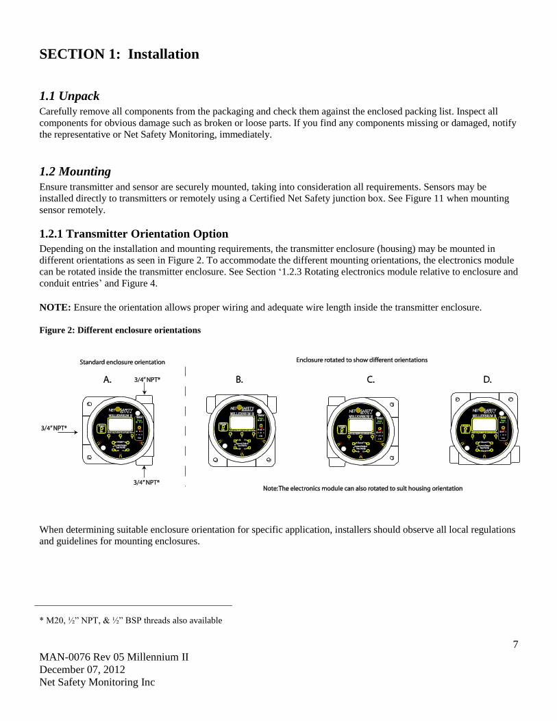
1.2.1 Transmitter Orientation Option
Depending on the installation and mounting requirements, the transmitter enclosure (housing) may be mounted in
different orientations as seen in Figure 2. To accommodate the different mounting orientations, the electronics module
can be rotated inside the transmitter enclosure. See Section ‘1.2.3 Rotating electronics module relative to enclosure and
conduit entries’ and Figure 4.
NOTE: Ensure the orientation allows proper wiring and adequate wire length inside the transmitter enclosure.
Figure 2: Different enclosure orientations
When determining suitable enclosure orientation for specific application, installers should observe all local regulations
and guidelines for mounting enclosures.
* M20, ½” NPT, & ½” BSP threads also available
8
MAN-0076 Rev 05 Millennium II
December 07, 2012
Net Safety Monitoring Inc
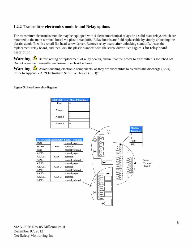
1.2.2 Transmitter electronics module and Relay options
The transmitter electronics module may be equipped with 4 electromechanical relays or 4 solid-state relays which are
mounted to the main terminal board via plastic standoffs. Relay boards are field replaceable by simply unlocking the
plastic standoffs with a small flat head screw driver. Remove relay board after unlocking standoffs, insert the
replacement relay board, and then lock the plastic standoff with the screw driver. See Figure 3 for relay board
description.
Warning Before wiring or replacement of relay boards, ensure that the power to transmitter is switched off.
Do not open the transmitter enclosure in a classified area.
Warning Avoid touching electronic components, as they are susceptible to electrostatic discharge (ESD).
Refer to Appendix A, “Electrostatic Sensitive Device (ESD)”.
Figure 3: Board assembly diagram

9
MAN-0076 Rev 05 Millennium II
December 07, 2012
Net Safety Monitoring Inc
1.2.3 Rotating electronics module relative to enclosure and conduit entries The electronics module consists of the relay board and faceplate (Display/CPU assembly) with main terminal board.
To rotate the electronics module, follow these instructions:
1. Turn off power to transmitter and ensure area is de-classified.
2. Remove the enclosure cover.
3. Unscrew both the locking knobs and free from two metal standoffs.
4. Lift transmitter faceplate from enclosure.
5. Disconnect existing wiring.
6. Unscrew the two metal standoffs using a ¼”hex tool.
7. Carefully remove the electronics module.
8. Rotate the electronics module to desired position.
9. Align metal standoffs with the mounting holes of the electronics module and enclosure base.
10. Insert metal standoffs in the appropriate mounting holes.
11. Tighten metal standoffs with ¼” hex tool to secure electronics module.
12. Reconnect wiring.
13. Replace faceplate, then fit and hand tighten locking knobs to metal standoffs by turning clockwise.
14. Replace enclosure cover.
Warning Before wiring or rotating electronics, ensure that the power to transmitter is switched off. Do not
open the transmitter enclosure in a classified area.
Warning Avoid touching electronic components, as they are susceptible to electrostatic discharge (ESD).
Refer to Appendix A, “Electrostatic Sensitive Device (ESD)”.
Figure 4: Rotating Electronics module
Note: To access enclosure grounding screw, remove the electronics module by following steps 1-7 above.

10
MAN-0076 Rev 05 Millennium II
December 07, 2012
Net Safety Monitoring Inc
SECTION 2: Wiring and installation
2.1 Field Installation
Warning Wiring codes and regulations may vary. ATEX requires that supply connection wiring must be rated
at least 5°C above the maximum ambient temperature of 85°C. Wiring must comply with all applicable regulations
relating to the installation of electrical equipment in a hazardous area and is the responsibility of the installer. If in
doubt, consult qualified personnel before wiring the system.
Warning Do not open the transmitter enclosure in a classified area (Do not open when an explosive
atmosphere may be present).
Guidelines
The safety ground connection of the transmitter is a Green screw found in the enclosure. See Figure 4 for
Ground screw location. Note: The electronics module has to be removed to access Ground screw. Follow steps
1-7 under Section ‘1.2.3 Rotating electronics module relative to enclosure and conduit entries’, when
removing electronics module.
If the 4-20mA signal is not used, connect a jumper between the 4 – 20mA terminal and the Common terminal
to allow analog current levels to be monitored at the Test Jacks on the faceplate.
The use of shielded cable is highly recommended for signal, input, output and power wires. Refer to Section
‘2.1.2 Cable choice and guidelines’ for recommended cable to help eliminate interference caused by
extraneous electrical or electromagnetic ‘noise’. To meet IEC 61000-1 and IEC 61000-4 EMI requirements,
follow the recommendations listed under Section ‘2.1.2 Cable choice and guidelines’.
In applications where wiring is installed in conduit, conduit must not be used for wiring to any other electrical
equipment.
For effective communication, Net Safety limits sensor separation to 2000 feet using 16AWG wires.
Modbus RS-485 connection 2-wire mode, multipoint serial line available. Up to 247 addresses allowed.
When developing a RS-485 chain of devices, the last device in the chain requires an end of line termination
resistor (120 Ohms).
Transmitter connector terminals accommodate wire from 14 to 20 AWG wires.
2.1.1 Seals
Warning The use of conduit wiring seals is recommended to protect the system against water ingression, and
equipment should be installed according to local electrical codes. Seals are especially recommended for installations
that use high-pressure or steam cleaning devices in proximity to the transmitter and/or sensor. The cementing material
used on the Millennium II sensors is suitable for an operating temperature range of
(-55°C to +85 °C).
Guidelines
It is recommended that explosion-proof drains and conduit breathers be used. In some applications, alternate
changes in temperature and barometric pressure can cause ‘breathing’ which allows moist air to enter and
circulate inside the conduit. Joints in the conduit system are seldom tight enough to prevent this ‘breathing’.
Threaded connections on the enclosure between the enclosure and conduit pipe need to be sealed with thread
tape, such as Teflon tape, or something similar.
Hydrophobic filters (IPF-001) may be used to protect sensors from water.

11
MAN-0076 Rev 05 Millennium II
December 07, 2012
Net Safety Monitoring Inc
It is the responsibility of the installer to install conduit seals where necessary, and to design conduit runs to
ensure that condensation does not accumulate and collect inside the enclosure.
2.1.2 Cable choice and guidelines
Radio Frequency Interference (RFI) can be caused by nearby electrical devices (transformers, high voltage equipment)
as well as handheld communications devices/radios, which when activated, may impede the proper functioning of the
transmitter and sensor. Selecting the right instrumentation cable and making proper grounding connections within the
junction box will reduce or eliminate interference. Visible symptoms of Radio Frequency Interference (RFI) include
inconsistent, incorrect and erratic LEL and PPM readings.
Important Wiring Guidelines
Fire and gas detection instruments are an important part of a safety alarm and shutdown system. The system is
composed of:
detection instruments
customer connected equipment
wiring
Net Safety designs and manufactures its detection equipment under rigid quality control management systems and
makes every effort to design for the harshest of industrial environments. The other components of the system – the
customer-connected equipment and wiring – are also important contributors to the overall quality and performance of
the safety system.
It is important to implement wiring that ensures the reliability and integrity of the safety system. Field wiring practices
and the choice of cable type specified vary from project to project. Poor practices and choices are often found to be the
source of unwanted system disruptions. Radio Frequency Interference (RFI) and Electro-Magnetic Interference (EMI)
are usually very powerful disruptive forces in industrial facilities and these forces act upon the system through the
wiring.
Follow the wiring specifications and guidelines in this manual carefully. The cable used should be a very high quality
instrument grade, certified for the application conditions, consisting of a rugged protective outer jacket, an overall
electrical shield of fine braided copper or metallic foil, and internal pairs or triads of foil shielded copper wire of
suitable gauge for the power conducted over the specified length.
The shields must be electrically continuous from the instrument junction box through other junction boxes and finally
to the connected equipment. The shield must be connected to a suitable ground sink as specified in the instrument
manual in order to protect the system from electrical disturbances.
Recommended cable and guidelines
The type of cable and shielding practices are especially important when sensor is separated from transmitter via
junction box. Net Safety recommends using CSA armored instrumentation cable (ACIC 2PR 16AWG, 300V, ISOS,
PVC) when rigid (steel) conduit is not used. See Figure 5. This cable should be used between the PLC/PANEL/DCS
and the Millennium II Transmitter, as well as between the Millennium II Transmitter and junction box.
Additional notes:
In general, communication cables and power cables should not run in parallel for any significant length, and should not
be carried in the same cable tray. Through inductance, high currents in power cables can induce significant ‘noise’ in
communication cables running parallel alongside power cables.
See cable preparation procedure on next page.

12
MAN-0076 Rev 05 Millennium II
December 07, 2012
Net Safety Monitoring Inc
Armored Cable preparation procedure:
1. Prepare the armored instrument cable as illustrated in Figure 5 and follow all assembly and/or preparation
instructions provided by the cable and/or cable gland manufacturer.
2. Install cable gland and reducer onto the cable.
3. Ensure four (4) inches of wire length is available for connecting to terminals inside the junction box.
4. Use a small flat head screw driver when connecting wires to connector terminals. See Figure 6.
5. Connect sensor wires to the appropriate terminals. See Figure 5C, Figure 9, Figure 12 and Figure 13.
Figure 5: Cable preparation
Note: If required, use cable glands which have been approved for hazardous locations.
4 Inches Hazloc cable gland
A: Drawing showing of cable without gland B. Picture of cable showing gland and insulation
C. Picture of cable wired to junction box and sensor
Millennium II
Sensor Cable gland &
Armored cable
Shield wires from each twisted pair
connected to “GND” (Earth Ground) on
terminal block.
Shield wire from flexible Armored
cable and sensor ground wire (Green
wire) connected to Earth grounding
screw in junction box ¾” NPT stopping
plug.
Net Safety
Junction Box
13
MAN-0076 Rev 05 Millennium II
December 07, 2012
Net Safety Monitoring Inc
Warning Before wiring, ensure that power to transmitter is switched off.
When connecting cable wires, use a small screwdriver to gently press down and hold the spring connector open. Insert
the appropriate wire into the open connector hole, releasing the screwdriver to secure the wire. See Figure 6.
Figure 6: Connecting wires
Warning Avoid touching electronic components, as they are susceptible to electrostatic discharge (ESD).
Refer to Appendix A, “Electrostatic Sensitive Device (ESD)”.
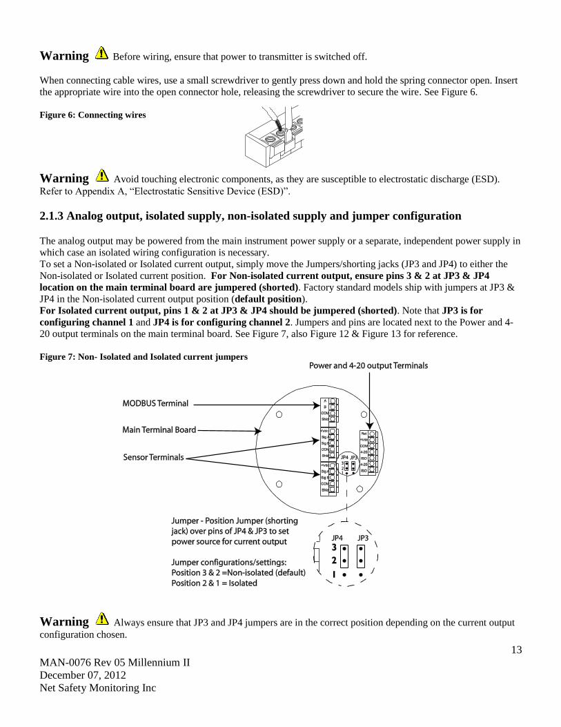
2.1.3 Analog output, isolated supply, non-isolated supply and jumper configuration The analog output may be powered from the main instrument power supply or a separate, independent power supply in
which case an isolated wiring configuration is necessary.
To set a Non-isolated or Isolated current output, simply move the Jumpers/shorting jacks (JP3 and JP4) to either the
Non-isolated or Isolated current position. For Non-isolated current output, ensure pins 3 & 2 at JP3 & JP4
location on the main terminal board are jumpered (shorted). Factory standard models ship with jumpers at JP3 &
JP4 in the Non-isolated current output position (default position).
For Isolated current output, pins 1 & 2 at JP3 & JP4 should be jumpered (shorted). Note that JP3 is for
configuring channel 1 and JP4 is for configuring channel 2. Jumpers and pins are located next to the Power and 4-
20 output terminals on the main terminal board. See Figure 7, also Figure 12 & Figure 13 for reference.
Figure 7: Non- Isolated and Isolated current jumpers
Warning Always ensure that JP3 and JP4 jumpers are in the correct position depending on the current output
configuration chosen.
14
MAN-0076 Rev 05 Millennium II
December 07, 2012
Net Safety Monitoring Inc
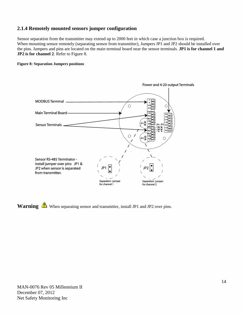
2.1.4 Remotely mounted sensors jumper configuration
Sensor separation from the transmitter may extend up to 2000 feet in which case a junction box is required.
When mounting sensor remotely (separating sensor from transmitter), Jumpers JP1 and JP2 should be installed over
the pins. Jumpers and pins are located on the main terminal board near the sensor terminals. JP1 is for channel 1 and
JP2 is for channel 2. Refer to Figure 8.
Figure 8: Separation Jumpers positions
Warning When separating sensor and transmitter, install JP1 and JP2 over pins.
15
MAN-0076 Rev 05 Millennium II
December 07, 2012
Net Safety Monitoring Inc
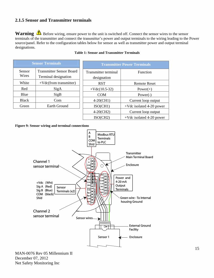
2.1.5 Sensor and Transmitter terminals
Warning Before wiring, ensure power to the unit is switched off. Connect the sensor wires to the sensor
terminals of the transmitter and connect the transmitter’s power and output terminals to the wiring leading to the Power
source/panel. Refer to the configuration tables below for sensor as well as transmitter power and output terminal
designations.
Table 1: Sensor and Transmitter Terminals
Sensor Terminals
Sensor
Wires
Transmitter Sensor Board
Terminal designation
White +Vdc(from transmitter)
Red SigA
Blue SigB
Black Com
Green Earth Ground
Figure 9: Sensor wiring and terminal connections
Transmitter Power Terminals
Transmitter terminal
designation
Function
RST Remote Reset
+Vdc(10.5-32) Power(+)
COM Power(-)
4-20(CH1) Current loop output
ISO(CH1) +Vdc isolated 4-20 power
4-20(CH2) Current loop output
ISO(CH2) +Vdc isolated 4-20 power
16
MAN-0076 Rev 05 Millennium II
December 07, 2012
Net Safety Monitoring Inc
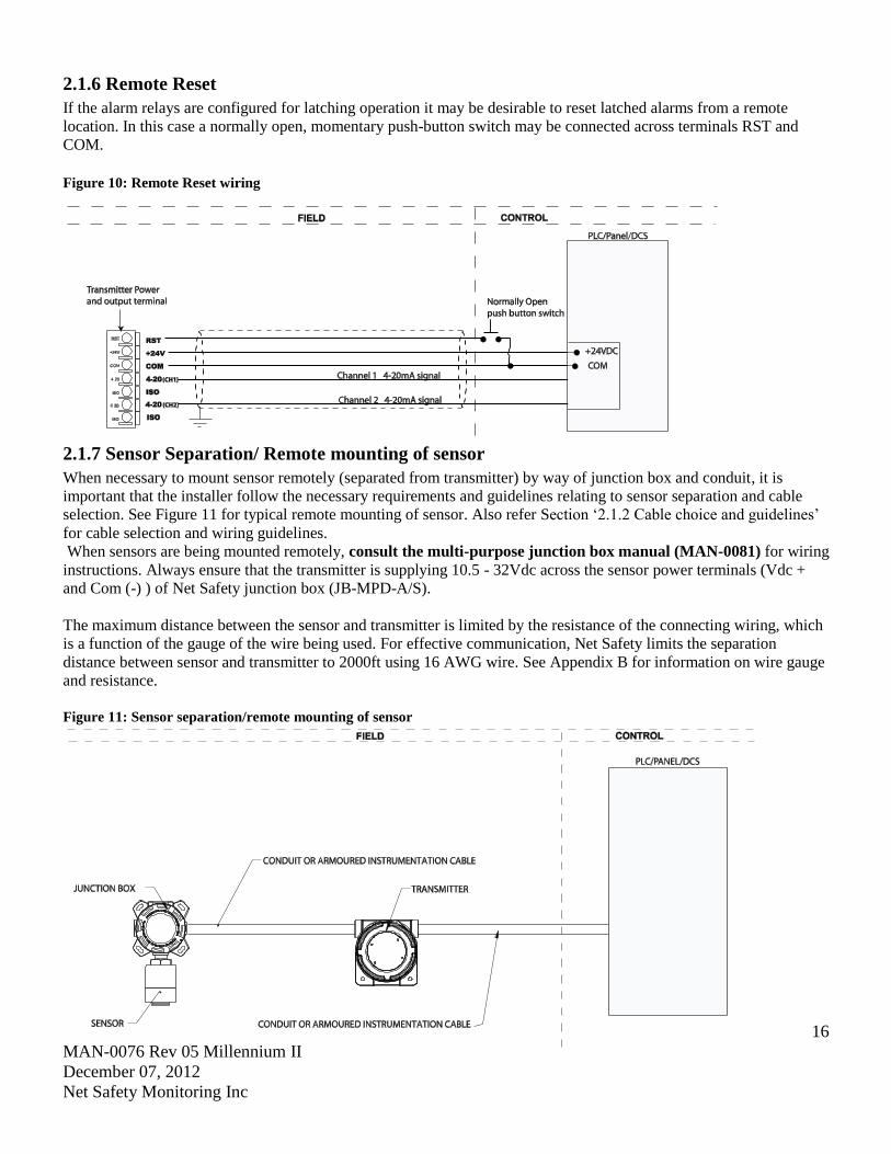
2.1.6 Remote Reset
If the alarm relays are configured for latching operation it may be desirable to reset latched alarms from a remote
location. In this case a normally open, momentary push-button switch may be connected across terminals RST and
COM.
Figure 10: Remote Reset wiring
2.1.7 Sensor Separation/ Remote mounting of sensor
When necessary to mount sensor remotely (separated from transmitter) by way of junction box and conduit, it is
important that the installer follow the necessary requirements and guidelines relating to sensor separation and cable
selection. See Figure 11 for typical remote mounting of sensor. Also refer Section ‘2.1.2 Cable choice and guidelines’
for cable selection and wiring guidelines.
When sensors are being mounted remotely, consult the multi-purpose junction box manual (MAN-0081) for wiring
instructions. Always ensure that the transmitter is supplying 10.5 - 32Vdc across the sensor power terminals (Vdc +
and Com (-) ) of Net Safety junction box (JB-MPD-A/S).
The maximum distance between the sensor and transmitter is limited by the resistance of the connecting wiring, which
is a function of the gauge of the wire being used. For effective communication, Net Safety limits the separation
distance between sensor and transmitter to 2000ft using 16 AWG wire. See Appendix B for information on wire gauge
and resistance.
Figure 11: Sensor separation/remote mounting of sensor
17
MAN-0076 Rev 05 Millennium II
December 07, 2012
Net Safety Monitoring Inc
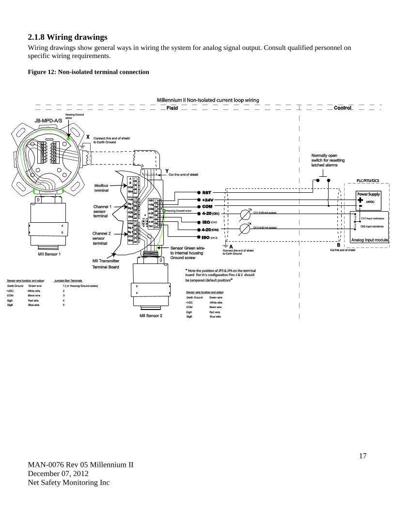
2.1.8 Wiring drawings
Wiring drawings show general ways in wiring the system for analog signal output. Consult qualified personnel on
specific wiring requirements.
Figure 12: Non-isolated terminal connection
18
MAN-0076 Rev 05 Millennium II
December 07, 2012
Net Safety Monitoring Inc
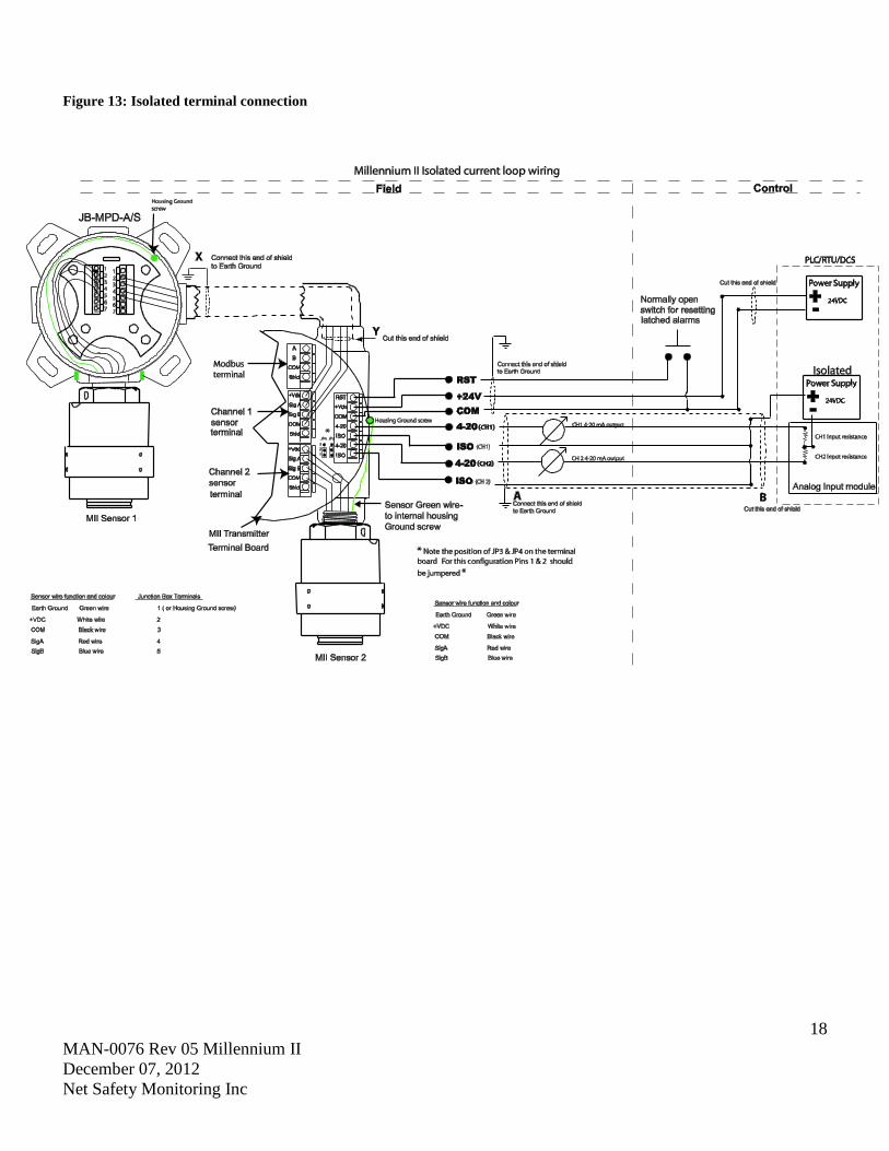
Figure 13: Isolated terminal connection
19
MAN-0076 Rev 05 Millennium II
December 07, 2012
Net Safety Monitoring Inc
2.1.9 Installation Checklist
Prior to operation, it is important to do the following checks.
Ensure transmitter and sensor are properly and firmly mounted.
Ensure that the enclosure certified stopping plug is tightened to unused conduit entry/opening, to maintain
ingress protection and flameproof type protection.
Ensure transmitter and sensor are not being obstructed; transmitter and sensor are accessible and target gas is
not inhibited from reaching sensor.
Remove sensor red protective plastic cap.
If hydrophobic filters (IPF-001) are being used, check for damage or debris. See the IP 66/67filter Instruction
guide (MAN-0109) for instructions.
If calibration cups (splash guards) are fitted to sensor, ensure a snug fit.
Ensure adherence to applicable local guidelines and requirements on wiring and sealing of equipment in
hazardous and non-hazardous areas.
Ensure that proper shielding and grounding practices are adhered to, and local codes are being followed.
Check system operational voltage and conditions. See Table 1 and Appendix C.
Check wiring at all termination and junction points; wiring at transmitter terminals, junction box and at power
supply. Refer to Table 1, also Figure 7, Figure 8, Figure 9, Figure 12 and Figure 13
20
MAN-0076 Rev 05 Millennium II
December 07, 2012
Net Safety Monitoring Inc
SECTION 3: Transmitter and faceplate description
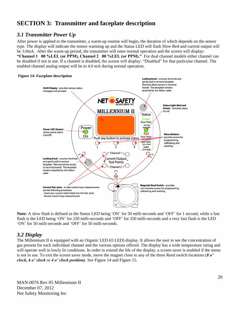
3.1 Transmitter Power Up
After power is applied to the transmitter, a warm-up routine will begin, the duration of which depends on the sensor
type. The display will indicate the sensor warming up and the Status LED will flash Slow Red and current output will
be 3.0mA. After the warm-up period, the transmitter will enter normal operation and the screen will display:
“Channel 1 00 %LEL (or PPM), Channel 2 00 %LEL (or PPM).” For dual channel models either channel can
be disabled if not in use. If a channel is disabled, the screen will display: “Disabled” for that particular channel. The
enabled channel analog output will be to 4.0 mA during normal operation.
Figure 14: Faceplate description
Note: A slow flash is defined as the Status LED being ‘ON’ for 50 milli-seconds and ‘OFF’ for 1 second, while a fast
flash is the LED being ‘ON’ for 250 milli-seconds and ‘OFF’ for 250 milli-seconds and a very fast flash is the LED
‘ON’ for 50 milli-seconds and ‘OFF’ for 50 milli-seconds.
3.2 Display The Millennium II is equipped with an Organic LED (O LED) display. It allows the user to see the concentration of
gas present for each individual channel and the various options offered. The display has a wide temperature rating and
will operate well in lowly lit conditions. In order to extend the life of the display, a screen saver is enabled if the menu
is not in use. To exit the screen saver mode, move the magnet close to any of the three Reed switch locations (8 o’
clock, 6 o’ clock or 4 o’ clock position). See Figure 14 and Figure 15.

21
MAN-0076 Rev 05 Millennium II
December 07, 2012
Net Safety Monitoring Inc
3.3 Status LED
The Status LED can be solid Red or Green, or flashing Red or Green to indicate various states of the transmitter and
sensor. Refer to “Sensor Status Registers, Status LEDs, Current Loop, and Display Messages”.
3.4 Current loop measurement (Test jacks) For convenience, a pair of test jacks for each analog output is provided on the front face of the display module. Attach
mA meter probes to these jacks to check loop current without opening the circuit to insert the meter. Refer to Figure 14
and Figure 15 for test jacks location.
Warning Do not open the transmitter enclosure in a classified area.
3.5 Menu buttons and access The main menu can be accessed in two ways: Intrusive (opening the enclosure and pressing menu buttons) and Non-
Intrusive (keeping the enclosure closed and using the magnet and reed switches).
3.5.1 Intrusive Access
The menu buttons provide access to the Millennium II’s Main Menu options allowing the user to review and configure
existing options under sub menus and perform calibration. There are three visible main menu buttons that are
located directly under the display screen. They are designated ‘1’, ‘2’ and ‘3’. See Figure 14 and Figure 15.
3.5.2 Non-Intrusive Access/Magnetic Reed switch Access Accessing the main menu and making a selection can also be done via an attached magnet and Reed switches.
The Reed switches are located in the 8 o’ clock, 6 o’ clock and 4 o’ clock positions on the face plate and indicated by
horse shoe shape print magnets. To select a Reed switch, place and hold the magnet close to the transmitter enclosure
at 8, 6 or 4 o’clock position. See Figure 14 and Figure 15.
Note: Menu buttons and reed switches provide the same functions. The term ‘switch’ is used throughout to represent
menu buttons and reed switches.
Figure 15: Switch positions
Note: menu buttons and reed
switch provide the same functions.
Menu button = reed switch,
indicated by ‘ ’
22
MAN-0076 Rev 05 Millennium II
December 07, 2012
Net Safety Monitoring Inc
SECTION 4: Operation
4.1 Menu options
The main menu provides access to various functional settings/options, as seen in the Table 2 below. Each menu option
has a submenu, whereby configuration is done.
Table 2: Main menu options
Calibrate Sensor Select Display Language Self-test Relay
Enable/Disable Channels Modbus Setup Sensor Upper Limit(Range)
Set Alarm Level Setup Current Date Select Gas Type
Set Relay Option Setup Current Time Cal. Gas Value
Relay Assignment View Events Log Serial Number and Firmware version
Relay Alarm Mode setting Manual Reset Exit
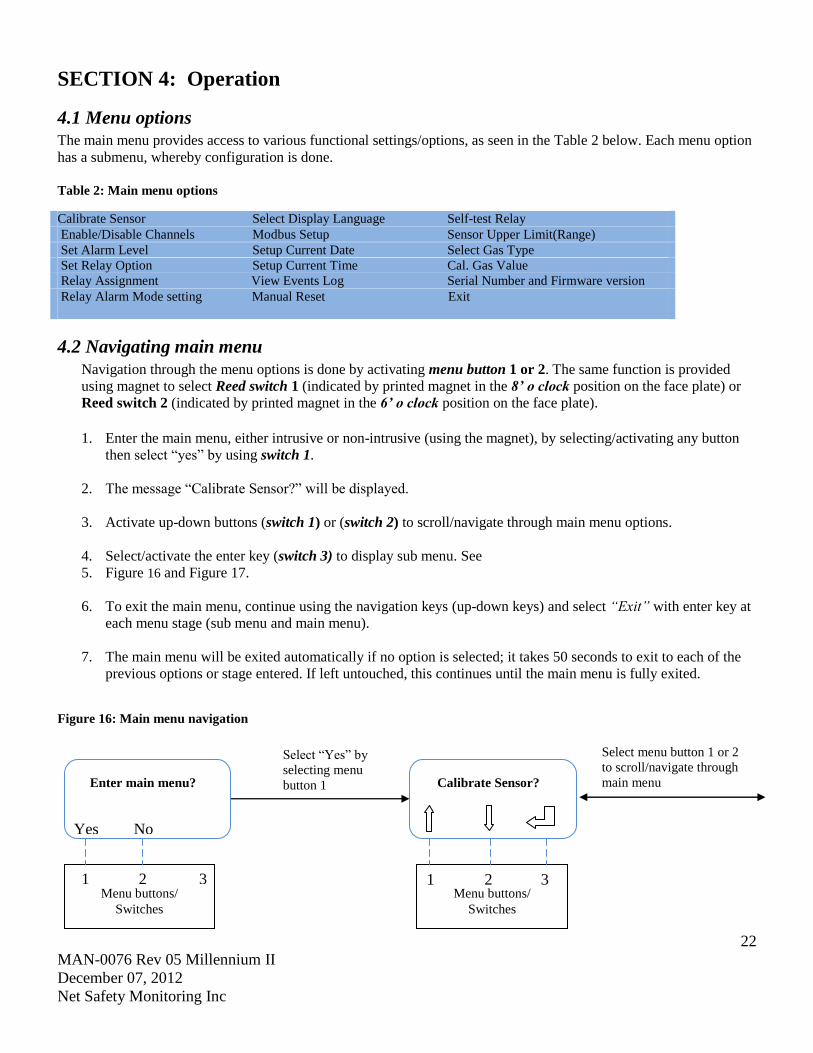
4.2 Navigating main menu
Navigation through the menu options is done by activating menu button 1 or 2. The same function is provided
using magnet to select Reed switch 1 (indicated by printed magnet in the 8’ o clock position on the face plate) or
Reed switch 2 (indicated by printed magnet in the 6’ o clock position on the face plate).
1. Enter the main menu, either intrusive or non-intrusive (using the magnet), by selecting/activating any button
then select “yes” by using switch 1.
2. The message “Calibrate Sensor?” will be displayed.
3. Activate up-down buttons (switch 1) or (switch 2) to scroll/navigate through main menu options.
4. Select/activate the enter key (switch 3) to display sub menu. See
5. Figure 16 and Figure 17.
6. To exit the main menu, continue using the navigation keys (up-down keys) and select “Exit” with enter key at
each menu stage (sub menu and main menu).
7. The main menu will be exited automatically if no option is selected; it takes 50 seconds to exit to each of the
previous options or stage entered. If left untouched, this continues until the main menu is fully exited.
Figure 16: Main menu navigation
Select “Yes” by
selecting menu
button 1
Select menu button 1 or 2
to scroll/navigate through
main menu Calibrate Sensor?
1 2 3
Menu buttons/
Switches
Enter main menu?
1 2 3
Yes No
Menu buttons/
Switches
23
MAN-0076 Rev 05 Millennium II
December 07, 2012
Net Safety Monitoring Inc
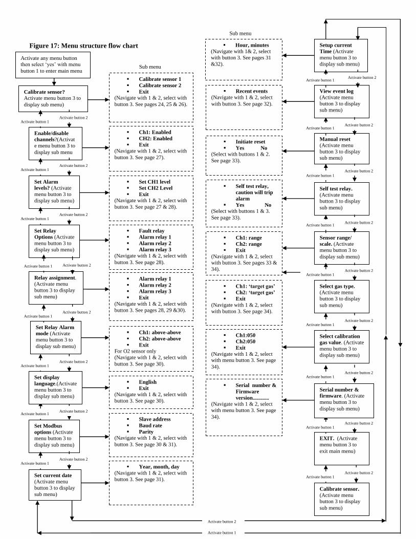
Figure 17: Menu structure flow chart
Serial number &
Firmware
version............
(Navigate with 1 & 2, select
with menu button 3. See page
34).
Ch1:050
Ch2:050
Exit
(Navigate with 1 & 2, select with menu button 3. See page
34).
Ch1: ‘target gas’
Ch2: ‘target gas’
Exit
(Navigate with 1 & 2, select
with button 3. See page 34).
Ch1: range
Ch2: range
Exit
(Navigate with 1 & 2, select
with button 3. See pages 33 &
34).
Self test relay,
caution will trip
alarm
Yes No
(Select with buttons 1 & 3.
See page 33).
Initiate reset
Yes No
(Select with buttons 1 & 2.
See page 33).
Recent events
(Navigate with 1 & 2, select
with button 3. See page 32).
Select calibration
gas value. (Activate
menu button 3 to
display sub menu)
Select gas type. (Activate menu
button 3 to display
sub menu)
Sensor range/
scale. (Activate menu button 3 to
display sub menu)
Self test relay. (Activate menu button 3 to display
sub menu)
Manual reset (Activate menu
button 3 to display
sub menu)
View event log (Activate menu
button 3 to display
sub menu)
Set Modbus
options (Activate menu button 3 to
display sub menu)
Set Relay Alarm
mode (Activate
menu button 3 to
display sub menu)
Relay assignment. (Activate menu
button 3 to display
sub menu)
Set Relay
Options (Activate
menu button 3 to
display sub menu)
Set Alarm
levels? (Activate
menu button 3 to
display sub menu)
Calibrate sensor? Activate menu button 3 to
display sub menu)
Ch1: Enabled
CH2: Enabled
Exit
(Navigate with 1 & 2, select with
button 3. See page 27).
Year, month, day
(Navigate with 1 & 2, select with
button 3. See page 31).
Slave address
Baud rate
Parity
(Navigate with 1 & 2, select with
button 3. See page 30 & 31).
English
Exit
(Navigate with 1 & 2, select with
button 3. See page 30).
Ch1: above-above
Ch2: above-above
Exit
For O2 sensor only
(Navigate with 1 & 2, select with
button 3. See page 30).
Alarm relay 1
Alarm relay 2
Alarm relay 3
Exit
(Navigate with 1 & 2, select with
button 3. See pages 28, 29 &30).
Fault relay
Alarm relay 1
Alarm relay 2
Alarm relay 3
(Navigate with 1 & 2, select with
button 3. See page 28).
Set CH1 level
Set CH2 Level
Exit
(Navigate with 1 & 2, select with
button 3. See page 27 & 28).
Calibrate sensor 1
Calibrate sensor 2
Exit
(Navigate with 1 & 2, select with
button 3. See pages 24, 25 & 26).
Set current date (Activate menu
button 3 to display
sub menu)
EXIT. (Activate
menu button 3 to
exit main menu)
Calibrate sensor. (Activate menu button 3 to display
sub menu)
Enable/disable
channels?(Activat
e menu button 3 to
display sub menu
Activate button 1 Activate button 2
Activate button 1 Activate button 2
Activate button 1 Activate button 2
Activate button 1 Activate button 2
Activate button 1 Activate button 2
Activate button 1 Activate button 2
Activate button 1 Activate button 2
Activate button 1 Activate button 2
Activate button 1 Activate button 2
Activate button 1 Activate button 2
Activate button 1 Activate button 2
Activate button 1 Activate button 2
Activate button 1 Activate button 2
Activate button 1 Activate button 2
Activate button 1 Activate button 2
Activate button 1 Activate button 2
Sub menu
Sub menu
Activate any menu button then select ‘yes’ with menu
button 1 to enter main menu
Activate button 2
Activate button 1
Serial number &
firmware. (Activate
menu button 3 to
display sub menu)
Set display
language.(Activate
menu button 3 to
display sub menu)
Setup current
Time (Activate
menu button 3 to
display sub menu)
Hour, minutes
(Navigate with 1& 2, select
with button 3. See pages 31
&32).
Activate button 2 Activate button 1

24
MAN-0076 Rev 05 Millennium II
December 07, 2012
Net Safety Monitoring Inc
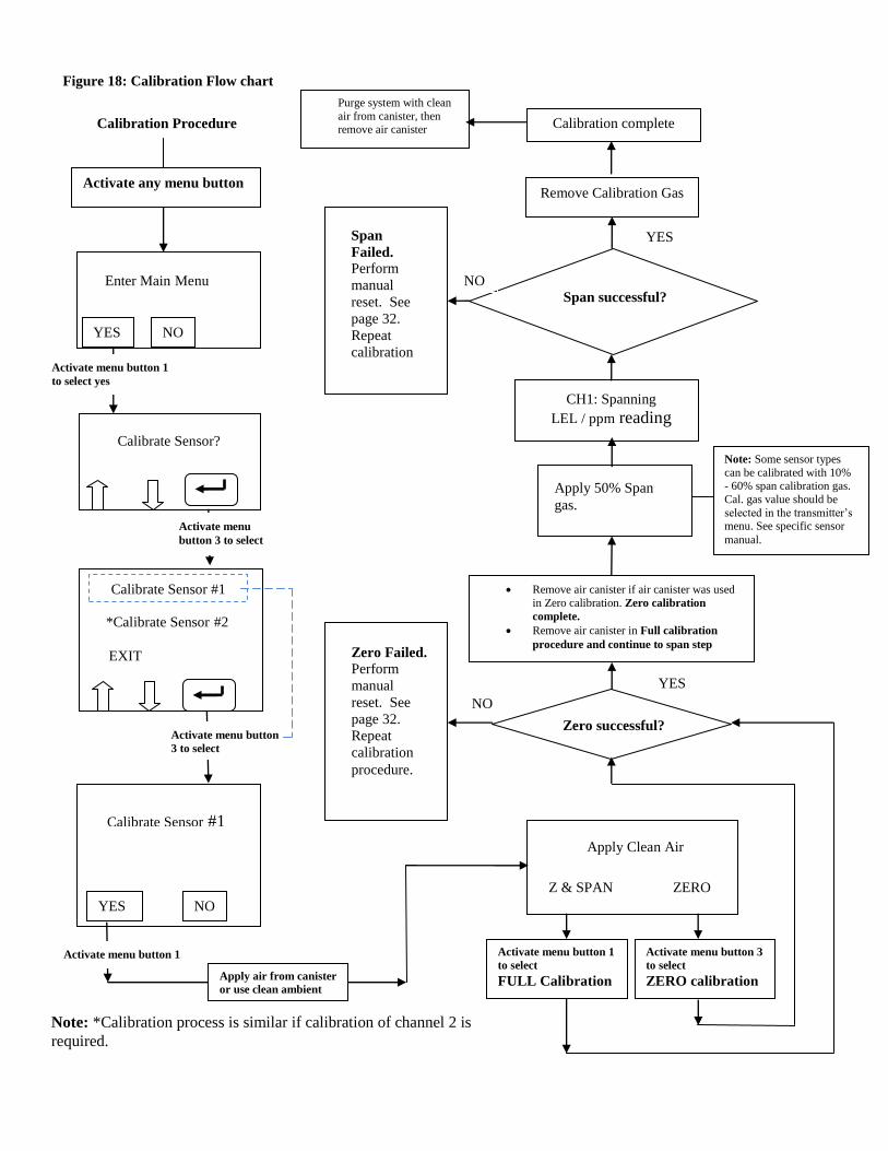
4.2.1 Full calibration (Normal calibration) procedure
Prior to attempting calibration read and understand the calibration procedure below. Also see Figure 18 for
additional reference.
The following calibration procedure should be followed to ensure an accurate correlation between the output signal
and the gas concentration. For accurate performance, the Millennium II is calibrated using 50% span gas. The
transmitter will however, allow some flexibility in the use of calibration gas with some sensors; calibration gas outside
of 50 % span (10% - 60% span gas) will be allowed on specific sensor models (see specific sensor manual for details).
The calibration gas value can be chosen by selecting it under “cal. gas value” in the main menu. A full calibration will
take approximately 5 minutes to complete.
Ensure the transmitter is functioning properly as indicated by the status LED and current output.
1. Enter the main menu by selecting/activating any key to get the “enter main menu” prompt, then activate
switch 1 to select “yes”.
2. When “Calibrate Sensor?” is displayed, activate the enter key (switch 3).
3. When “Calibrate Sensor #1?” is highlighted, activate the enter key (switch 3) if this is the sensor to be
calibrated.
4. If sensor #2 is to be calibrated, select the down arrow key (switch 2) to scroll to “Calibrate Sensor #2?”
5. Select the desired sensor to be calibrated (1 or 2) by activating the enter key (switch 3).
6. Select “YES” with switch 1 to confirm the selection, and then apply clean air (zero gas) from canister when
“Apply Clean Air” is displayed. Ensure no contaminant gases are around if ambient air is being used.
7. Select “Z & Span” using switch 1 for normal (full) calibration. “Setting zero” will be displayed as the sensor
is being zeroed.
8. Apply 50% calibration gas (* or % cal. gas value chosen) when prompted.
9. The display will show “Spanning” with the gas value (%LEL or PPM depending on the sensor) as the gas is
detected.
10. Remove the calibration gas when “Remove Cal Gas” is displayed.
11. “Cal Complete” will be displayed when calibration is complete.
12. Apply zero gas (clean air) to purge system. This is particularly important when using long tubing.
* Note: Selectable calibration gas value (% cal. gas value) is only available for some sensor types.
Warning Always apply test gas after any calibration to verify accuracy; do a bump test after calibration. When
applying test gas, make sure the system is bypassed to avoid unwanted shutdowns.
25
MAN-0076 Rev 05 Millennium II
December 07, 2012
Net Safety Monitoring Inc
4.2.2 (Cont’d) Zero calibration option The “Zero” calibration option is selected if the sensor is only being zeroed (this not a complete calibration)
It does not require the application of span gas, as only the sensor’s zero point is adjusted. Ensure that no contaminants
are present, if the surrounding air is to be used for Zeroing. If Zero calibration is needed, at step 7 above, select ‘Zero’
using switch 3).
Warning Air movement, drafts and wind can cause dilution of calibration gas flow which can cause an
erroneous calibration and inaccurate performance. To avoid this, use a Calibration Cup attached to the bottom of the
sensor. The cup doesn’t have to be removed for normal operation. When the cup is in place, inject calibration gas at a
rate of 0.5 – 1.0 liter per minute.
26
MAN-0076 Rev 05 Millennium II
December 07, 2012
Net Safety Monitoring Inc
Figure 18: Calibration Flow chart
YES NO
Activate menu button 1
to select yes
Calibrate Sensor?
Enter Main Menu rate Sensor?
Activate menu button
3 to select
Calibrate Sensor #1
*Calibrate Sensor #2
Calibrate Sensor #1
YES NO
Activate menu button 1
Apply Clean Air
Z & SPAN ZERO
Apply air from canister
or use clean ambient
air
Remove Calibration Gas
Remove air canister if air canister was used
in Zero calibration. Zero calibration
complete.
Remove air canister in Full calibration
procedure and continue to span step
Activate menu button 1
to select
FULL Calibration
Activate menu button 3
to select
ZERO calibration
Note: Some sensor types
can be calibrated with 10% - 60% span calibration gas.
Cal. gas value should be
selected in the transmitter’s menu. See specific sensor
manual.
CH1: Spanning
LEL / ppm reading
Span
Failed. Perform
manual
reset. See
page 32.
Repeat
calibration
.proceure.
Zero Failed. Perform
manual
reset. See
page 32.
Repeat
calibration
procedure.
Activate any menu button
NO
YES
Span successful?
Calibration complete
NO
YES
Calibration Procedure
Purge system with clean
air from canister, then
remove air canister
Zero successful?
Apply 50% Span
gas.
EXIT
Activate menu
button 3 to select
Note: *Calibration process is similar if calibration of channel 2 is
required.

27
MAN-0076 Rev 05 Millennium II
December 07, 2012
Net Safety Monitoring Inc
4.2.3 Enable / Disable channels
This option allows the Millennium II Transmitter channels to be enabled or disabled. The default value is channel
1(CH1) enabled for single sensor models while channel 2(CH2) is permanently disabled. Both channels are enabled for
two sensor models.
1. Enter the main menu by selecting/activating any key to get the “enter main menu” prompt, then activate switch 1
to select “yes”.
2. Select the down arrow key (switch 2) with the magnet, and scroll to “Enable/Disable Channel?”
3. Activate the enter key (switch 3) to enter the option. The sub menu options: ‘CH 1 Enabled’ and ‘CH 2 Enabled’
will be highlighted.
4. To disable a channel 1, Activate the enter key (switch 3). “CH1 disabled” will now be highlighted / displayed.
5. To disable channel 2, highlight ‘CH2 Enabled’ use switch 2, then activate the enter key (switch 3) to configure to
‘CH2 disabled’.
6. To exit the main menu, select “Exit” with enter key at each menu stage (sub menu and main menu).
4.2.4 Viewing and setting alarm levels (points)
This option enables the channel low and high alarm levels to be viewed and set-up. Alarm levels (points) for each
channel are user determined. Alarm Point 1 and Point 2 for channel 1 does not relate to Alarm Point 1 and Point 2 for
channel 2.
1. Enter the main menu by selecting/activating any key to get the “enter main menu” prompt, then activate switch 1
to select “yes”.
2. Activate the up key (switch 1) or the down key (switch 2) until “Set Alarm Level?” is highlighted / displayed.
3. Activate switch 3 to enter the “Set Alarm Level” option. Sub menu options ‘Set CH1 Level’, ‘Set CH2 Level’ and
‘Exit’ will be displayed. ‘Set CH1 Level’ being highlighted.
4. To view channel 1 alarm points, activate switch 3. ‘CH1 Point 1’ and ‘CH1 Point 2’ will be displayed.
5. To view channel 2 alarm points use switch 2, at step 3, highlight ‘Set CH2 Level’, then activate switch 3. ‘CH2
Point 1’ and ‘CH2 Point 2’ will be displayed.
6. To configure channel 1 alarm levels (Point 1 or Point 2), after step 4, use switch 3 to select CH 1 Point 1
(already highlighted) then proceed to step 8, or highlight CH1 Point 2 using switch 2 , then activate switch 3 and
proceed to step 8.
7. To configure channel 2 alarm levels (Point 1 or Point 2), after step 5, use switch 3 to select CH2 Point 1 then
proceed to step 8, or use switch 2 to highlight CH2 Point 2, then activate switch 3 to make a selection. Proceed to
step 8.
8. Use switch 1 to increase the existing values representing previously set alarm levels/points and switch 2 to
highlight and scroll across values.
9. After setting desired alarm points, select “Exit” at each menu stage (sub menu and main menu).

28
MAN-0076 Rev 05 Millennium II
December 07, 2012
Net Safety Monitoring Inc
10. Apply test gas to confirm alarm level settings.
Important: Alarm Point 1 and Alarm Point 2 are values completely under the control of the user. If the user chooses,
Alarm Point 1 can be assigned a value corresponding to a high alarm condition and Alarm Point 2 assigned a value
corresponding to a low alarm condition.
To avoid confusion however, most users may want to assign Alarm Point 1 as the low alarm condition and Alarm point
2 as the high alarm condition.
4.2.5 Setting Relay options This option allows the Alarm relay coils to be configured as energized or de-energized and latching or non-latching.
• FAULT RELAY: The Fault relay is Energized and Non-Latching. This relay is not configurable.
• ALARM RELAYS 1, 2 and 3: Factory set as De-energized and Non-Latching. These relays are configurable.
1. Enter the main menu by activating any key to get the “enter main menu” prompt, then activate switch 1 to select
“yes”.
2. Activate the up key (switch 1) or down key (switch 2) until, “Set Relay Options?” is displayed.
3. Activate the enter key (switch 3) to enter the option. The sub menu options are: ‘Fault relay’, ‘Alarm relay 1’,
‘Alarm relay 2’, ‘Alarm relay 3’.
4. Activate the down key (switch 2) or up key (switch 1) to highlight configurable Alarm relays (‘Alarm relay 1’,
‘Alarm relay 2’, ‘Alarm relay 3’).
5. Activate the enter key (switch 3) to configure the desired Alarm relay.
6. ‘Norm. Energized’ or ‘Norm.De-Energized’ will be highlighted at the top of the display screen. To change the
Energized or De-Energized setting, activate the enter key (switch 3).
7. To change the Latching or Non-Latching setting, activate the down key (switch 2) to highlight ‘Latching’ or
‘Non- Latching’, then activate the enter key (switch 3).
8. Once the desired relay settings have been made, select “Exit” at each menu stage (sub menu and main menu).
4.2.6 Relay Assignment
This option allows the transmitter two (2) channels (with alarm levels/points) to be configured under the three (3)
Alarm relays. When configuring under sub menu Alarm relay 1, “RL1:CH1 (Point 1, Point 2, Disabled)” and “RL1:
CH2 (Point 1, Point 2, Disabled)” is displayed. Under sub menu Alarm relay 2, “RL2:CH1 (Point 1, Point 2,
Disabled)” and “RL2:CH2 (Point 1, Point 2, Disabled)” is displayed, and under sub menu Alarm relay 3, “RL3:CH1
(Point 1, Point 2, Disabled)” and “RL3:CH2 (Point 1, Point 2, Disabled)”is displayed.
Note 1: RL1, RL2 and RL3 represents Alarm relays 1, 2 and 3. CH1 and CH2 represent channel1 and channel 2. Point
1 and Point 2 are Alarm level 1 and Alarm level 2. Alarm levels (points) are user determined and are unique to the
specific channel.
Note 2: Prior to assigning relays, configure the alarm levels (points). See Section ‘4.2.4 Viewing and setting alarm
levels (points)’, and then follow the steps and example below to configure the Alarm relays. Also see Table 3,
Example and Table 4.
29
MAN-0076 Rev 05 Millennium II
December 07, 2012
Net Safety Monitoring Inc
1. Enter the main menu by activating any key to get the “enter main menu” prompt, then activate switch 1 to
select “yes”.
2. Activate the up key (switch 1) or down key (switch 2) until “Relay Assignment?” is displayed.
3. Activate the enter key (switch 3) to enter the option. The sub menu: ‘Alarm Relay 1’, ‘Alarm Relay 2’, ‘Alarm
Relay 3’ as well as ‘Exit’ will be displayed.
4. Choose the Alarm relay (Alarm relay 1, Alarm relay 2, Alarm relay 3) for configuration, by using the up-
down arrow keys.
5. Activate the enter key (switch 3) to make the selection. The relay (RL) and channel (CH) with alarm level
setting will be highlighted. The alarm level settings available are: Point 1, Point 2, and Disabled.
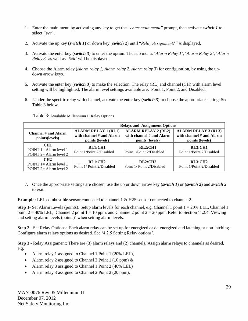
6. Under the specific relay with channel, activate the enter key (switch 3) to choose the appropriate setting. See
Table 3 below.
Table 3: Available Millennium II Relay Options
7. Once the appropriate settings are chosen, use the up or down arrow key (switch 1) or (switch 2) and switch 3
to exit.
Example: LEL combustible sensor connected to channel 1 & H2S sensor connected to channel 2.
Step 1- Set Alarm Levels (points): Setup alarm levels for each channel, e.g. Channel 1 point 1 = 20% LEL, Channel 1
point 2 = 40% LEL, Channel 2 point 1 = 10 ppm, and Channel 2 point 2 = 20 ppm. Refer to Section ‘4.2.4: Viewing
and setting alarm levels (points)’ when setting alarm levels.
Step 2 - Set Relay Options: Each alarm relay can be set up for energized or de-energized and latching or non-latching.
Configure alarm relays options as desired. See ‘4.2.5 Setting Relay options’.
Step 3 - Relay Assignment: There are (3) alarm relays and (2) channels. Assign alarm relays to channels as desired,
e.g.
Alarm relay 1 assigned to Channel 1 Point 1 (20% LEL),
Alarm relay 2 assigned to Channel 2 Point 1 (10 ppm) &
Alarm relay 3 assigned to Channel 1 Point 2 (40% LEL)
Alarm relay 3 assigned to Channel 2 Point 2 (20 ppm).
Relays and Assignment Options
Channel # and Alarm
points(levels)
ALARM RELAY 1 (RL1)
with channel # and Alarm
points (levels)
ALARM RELAY 2 (RL2)
with channel # and Alarm
points (levels)
ALARM RELAY 3 (RL3)
with channel # and Alarm
points (levels)
CH1
POINT 1= Alarm level 1
POINT 2= Alarm level 2
RL1:CH1
Point 1/Point 2/Disabled RL2:CH1
Point 1/Point 2/Disabled RL3:CH1
Point 1/Point 2/Disabled
CH2
POINT 1= Alarm level 1
POINT 2= Alarm level 2
RL1:CH2
Point 1/ Point 2/Disabled RL2:CH2
Point 1/ Point 2/Disabled RL3:CH2
Point 1/Point 2/Disabled

30
MAN-0076 Rev 05 Millennium II
December 07, 2012
Net Safety Monitoring Inc
Table 4: Typical Millennium II Relay Configurations
Note 1: In above example, alarm relay 3 (RL3) will trigger whenever any alarm level 2(point 2) is reached.
Note 2: For the single channel relay model transmitter, all (3) alarm relays are available for channel 1.
4.2.7 Relay Alarm Mode setting (for Oxygen sensors only)
This option is available for detecting oxygen levels. The user is allowed to set up two Alarm points/level (normal
oxygen level is 20.9 %) under three available Alarm Modes. These Alarm Modes are: Above-Above, Below-Below
and Below-Above. The Alarm Mode chosen by the user depends on the particular application/operation. If
surrounding air is to be used for calibration, ensure that no contaminants are present. Refer to the Oxygen Sensor
Manual (MAN-0093) for detailed information.
4.2.8 Select Display Language
This option allows the display language to be selected. The default language is English. There are also options for
Spanish, French, and Portuguese.
1. Enter the main menu by activating any key to get the “enter main menu” prompt then activate switch 1 to
select “yes”.
2. Activate the up key (switch 1) or down key (switch 2) until “Select Display Language?” is displayed.
3. Activate the enter key (switch 3). The default language, ‘English’, will be displayed.
4. Locate other languages by activating the enter key (switch 3).
5. Once the desired language is displayed, select “Exit” at each menu stage (sub menu and main menu).
4.2.9 MODBUS Setup
This option enables the following MODBUS parameters to be set:
• Addressing: From 001 (default) to 247
• Baud Rate: 02400 bps, 04800 bps, 09600 bps (default), 19200 bps, and 57600 bps.
• Frame Format: EVEN Parity (default), ODD Parity, NO Parity.
1. Enter the main menu by activating any key to get the “enter main menu” prompt, then activate switch 1 to
select “yes”.
2. Select the up arrow key (switch 1) or down arrow key (switch 2) until “Modbus Setup” option is displayed.
Relay Assignment Example
Channel # and selected
Alarm points (levels) ALARM RELAY 1 (RL1) ALARM RELAY 2 (RL2) ALARM RELAY 3 (RL3)
CH1
POINT 1=20% lel
POINT 2=40% lel
RL1:CH1
POINT 1=20% lel
RL2:CH1
Disabled
RL3:CH1
POINT 2=40% lel
CH2
POINT 1=10 ppm
POINT 2=20 ppm
RL1:CH2
Disabled
RL2:CH2
POINT 1=10 ppm
RL3:CH2
POINT 2=20 ppm

31
MAN-0076 Rev 05 Millennium II
December 07, 2012
Net Safety Monitoring Inc
3. Activate the enter key (switch 3) to display ‘slave address’ (default address: 001).
4. Use the up key (switch 1) to increase the address and the down key (switch 2) to decrease the value. The value
range is 001-247.
5. Activate the enter key (switch 3) when the desired value is displayed.
6. After setting the Slave Address, exit to this sub menu option using switch 3.
7. Activate the down key (switch 2) to highlight ‘baud rate’, then activate the enter key (switch 3) to display the
current baud rate.
8. Use the up key (switch 1) to increase the baud rate and the down key (switch 2) to decrease it.
9. Activate the enter key (switch 3) when the desired value is displayed.
10. After setting the baud rate, exit this sub menu option using switch 3, and then activate the down arrow key
(switch 2) to highlight ‘Parity Bit’.
11. Activate switch 3, then activate the up key (switch 2), or the down key (switch 1) to choose a value.
12. Activate the exit key (switch 3) when the desired value is displayed, then select “Exit” at each menu stage
(sub menu and main menu).
4.3.0 Setup Current Date
This option allows you to set the current date for event logging. The default date is set at the factory in Mountain Time
(MT).
1. Enter the main menu by selecting/activating any key to get the “enter main menu” prompt, then activate
switch 1 to select “yes”.
2. Activate the up key (switch 1) or down key (switch 2) until “Setup Current Date?” option is displayed.
3. Activate the enter key (switch 3) to display the sub menu option ‘year’, ‘month’, ‘day’.
4. Activate the up key (switch 1) to change the current year/month/day settings and switch 2 to cycle across
‘year’, ‘month’, ‘day’ values and ‘OK’.
13. After desired setting are made, navigate to “OK?” and activate the enter key (switch 3) to confirm. To exit
main menu, select “Exit” at each menu stage (sub menu and main menu).
4.3.1 Setup Current Time
This option allows you to set the current time for event logging. The default time is in Mountain Time (MT)
1. Enter the main menu by activating any key to get the “enter main menu” prompt, then activate switch 1 to
select “yes”.
2. Activate the up key (switch 1) or down (switch 2) until “Setup Current Time?” option is displayed.
32
MAN-0076 Rev 05 Millennium II
December 07, 2012
Net Safety Monitoring Inc
3. Activate the enter key (switch 3) to display the sub menu: hour’, ‘minute’, ‘seconds’.
4. Activate the up arrow key (switch 1) to change the current hour/minute/second settings, then use switch 2 to
cycle across ‘hour’, ‘minute’, ‘seconds’ values and ‘OK’.
5. After desired settings are made, navigate to ‘OK’ and activate the enter key (switch 3) to confirm. To exit main
menu, select “Exit” at each menu stage (sub menu and main menu).
4.3.2 View Event Log
The Millennium II Transmitter has the ability to store up to 980 events. Events can be viewed by navigating through
this menu option. The most recent events are shown first.
1. Enter the main menu by activating any key to get the “enter main menu” prompt, then activate switch 1 to
select “yes”.
2. Navigate through the main menu using switch1 or switch 2 until “View Event Log?” is displayed.
3. Activate the enter key (switch 3) to display the sub menu. The most recent event will be displayed.
4. Select the up arrow key (switch 1) and the down arrow key (switch 2) to toggle through all past events.
6. After viewing, select “Exit” at each menu stage (sub menu and main menu).
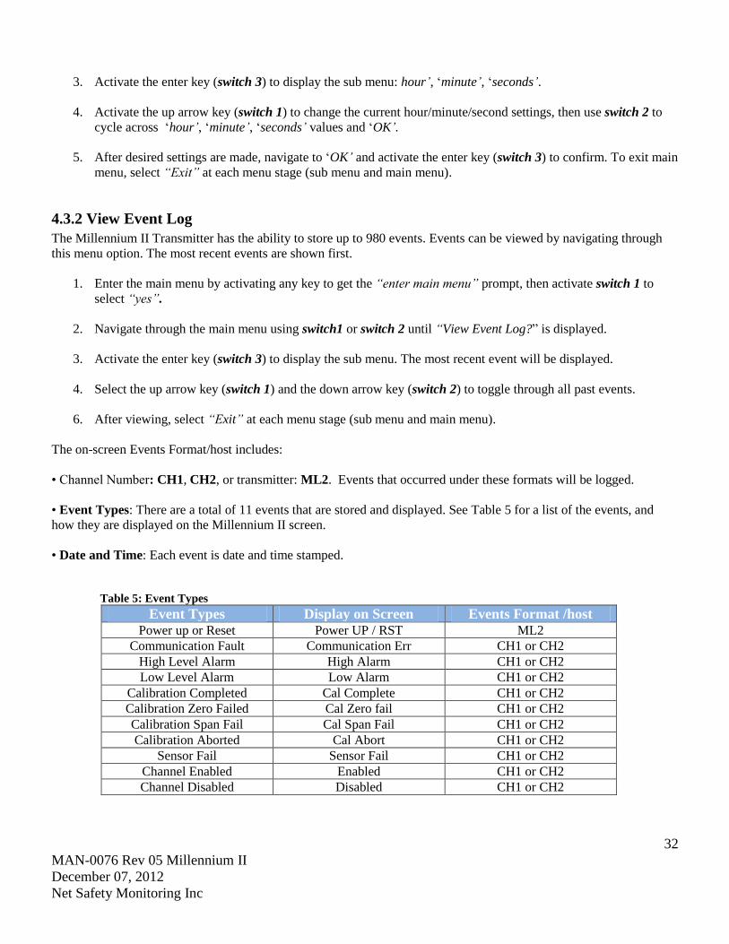
The on-screen Events Format/host includes:
• Channel Number: CH1, CH2, or transmitter: ML2. Events that occurred under these formats will be logged.
• Event Types: There are a total of 11 events that are stored and displayed. See Table 5 for a list of the events, and
how they are displayed on the Millennium II screen.
• Date and Time: Each event is date and time stamped.
Table 5: Event Types
Event Types Display on Screen Events Format /host Power up or Reset Power UP / RST ML2
Communication Fault Communication Err CH1 or CH2
High Level Alarm High Alarm CH1 or CH2
Low Level Alarm Low Alarm CH1 or CH2
Calibration Completed Cal Complete CH1 or CH2
Calibration Zero Failed Cal Zero fail CH1 or CH2
Calibration Span Fail Cal Span Fail CH1 or CH2
Calibration Aborted Cal Abort CH1 or CH2
Sensor Fail Sensor Fail CH1 or CH2
Channel Enabled Enabled CH1 or CH2
Channel Disabled Disabled CH1 or CH2
33
MAN-0076 Rev 05 Millennium II
December 07, 2012
Net Safety Monitoring Inc
4.3.3 Manual Reset
A Manual Reset is required after a calibration failure or to clear a latched Alarm relay. When a manual reset is done,
the transmitter will return to normal operation.
1. Enter the main menu by activating any key to get the “enter main menu” prompt, then activate switch 1 to
select “yes”.
2. Activate the up key (switch 1) or down key (switch 2) until “Manual Reset?” option is displayed.
3. Activate the enter key (switch 3) to display the sub menu: ‘Initiate Reset’.
4. Select “yes” using switch 1 to reset.
4.3.4 Self Test Relay
The Self test relay option continuously turns relays on and off to ensure that they are functioning properly. The
Fault Relay is tested first, automatically followed tests on Relay 1, 2, and 3. After the relays have been tested,
“Relay Test Complete” will be displayed. See steps to initiate relay self test below.
Proper functioning electromechanical relays have a clicking sound during this test. If the Millennium II
Transmitter is equipped with Solid State relays, then an Ohm meter must be used to check the changes in
resistance values between contacts.
Warning When checking self-test relay function, ensure all external equipment is disabled to prevent
unwanted alarm activation. Enable external equipment once testing is completed.
1. Enter the main menu by activating any key to get the “enter main menu” prompt, then activate switch 1 to
select “yes”.
2. Activate the up arrow key (switch 1) or down arrow key (switch 2) until “Self test Relay?” option is displayed.
3. Activate the enter key (switch 3) to display the sub menu: ‘Self Test Relay. Caution, will trip alarm’.
4. Select “yes” using switch 1. ‘Ensure alarm response items are disconnected’ will be displayed.
5. Ensure all external alarm devices are de-activated, and then select “yes” using switch 1.
6. After test is successfully completed, select “Exit”.
If a relay is malfunctioning, the transmitter should be sent to Net Safety’s Service Department for repair.
4.3.5 Sensor Upper Limit (Range)
This option is used to set the upper limit (range) of the gas being detected. The upper limit will vary depending on the
sensor used and may not be selectable for all sensors.
1. Enter the main menu by activating any key to get the “enter main menu” prompt, then activate switch 1 to
select “yes”.
2. Activate the up key (switch 1) or down key (switch 2), until “Sensor Upper Limit (Range)”option is displayed.
3. Activate the enter key (switch 3) to display the sub menu: ‘CH1: range’, ‘CH2: range’.
34
MAN-0076 Rev 05 Millennium II
December 07, 2012
Net Safety Monitoring Inc
4. Select the channel (sensor) to be configured and adjust the sensor’s range using the up-down arrow keys
(switch 1) or (switch 2). The specific sensor provides the upper limits/ranges.
Note: If no selections appear when activating the up/down arrow keys at this stage, the specific sensor only has
one upper limit/range, which cannot be altered.
5. Activate the enter key (switch 3) when the desired upper limit/range is reached.
6. To exit, select “Exit” at each menu stage (sub menu and main menu).
4.3.6 Select Gas Type “Select Gas Type” option allows the user to select a particular target gas and/or Correction (“K”) Factor in the case of
Catalytic Bead sensors or choose the type of LEL gas (gas curve) in the case of IR sensors. See specific sensor manual
in relation to this menu option.
4.3.7 Calibration gas value
This option allows the user to select the calibration gas value in the transmitter main menu. Although it is
recommended that 50% span gas should be used for calibration, for some sensors, the transmitter will allow
tolerance/flexibility in the calibration gas available; 10% to 60% span gas allowed for some sensor types. See specific
sensor manual.
1. Enter the main menu by activating any key to get the “enter main menu” prompt, then activate switch 1 to
select “yes”.
2. Activate the up key (switch 1) or down key (switch 2), until “Cal. Gas value” option is displayed.
3. Activate the enter key (switch 3). Channel1 and channel 2 existing calibration gas values will be displayed in
three numeric groups: ‘hundreds’, ‘tens’, and ‘ones’. For example: 0 5 0 indicates a calibration gas value of
50% span.
4. Highlight the required channel with calibration gas value using the navigation keys (switch1) or (switch 2),
then select using switch 3. Switch 1 is used to increase /change a value in each numeric group, while switch 2
is used to cycle across the numeric groups.
5. To exit, select “Exit” at each menu stage (sub menu and main menu).
4.3.8 Serial Number & Firmware Version
This option is used when the serial number or firmware version of the Millennium II Transmitter is required.
1. Enter the main menu by activating any key to get the “enter main menu” prompt, then activate switch 1 to
select “yes”.
2. Activate the up key (switch 1) or down key (switch 2), until “Serial Number and Firmware Version” option is
displayed.
3. Activate the enter key (switch 3). The firmware version and serial number will be displayed.
4. To exit, select “Exit” at each menu stage (sub menu and main menu).
35
MAN-0076 Rev 05 Millennium II
December 07, 2012
Net Safety Monitoring Inc
SECTION 5: Monitoring and outputs
5.1Fault monitoring
Self-testing circuitry continuously checks for problems that could prevent proper response. When power is applied to
the Millennium II Transmitter, a micro controller automatically tests the system to ensure that it is functioning
properly. During normal operation, it continuously monitors the signal from the internal sensor source. In addition, a
“watchdog” timer is maintained to ensure the program is running correctly. When a system fault is detected, the Status
LED will have a Red fast flash and the fault signal will output a 2.5 mA signal. The transmitter’s event log may be
viewed in order to distinguish the fault condition. Refer to the Event Log menu option.
Warning The fault detection circuitry does not monitor the operation of external response equipment or
external wiring to the transmitter. It is important that external equipment and wiring be checked periodically to ensure
they are operational.
5.2 Relays
Standard electro-mechanical relays have Form C SPDT contacts rated 5 Amps at 30 VDC/ 250 VAC. There are four
physical relays; one Fault and three Alarm relays. These relays have Normally Open and Normally Closed contacts at
the output terminals. Solid State relays are Form A contacts rated 2.5 Amps at 60 VAC/DC. These relays also have one
Fault and three Alarm relays.
Alarm relays are configurable and can be assigned values; the user is allowed to assign values corresponding to desired
alarm conditions, under Relay 1, Relay 2 or Relay 3 for each channel. Relays can be selected to be ‘Energized’ or
‘De-energized’ and ‘Latching’ or ‘Non-latching’. See “relay assignment” option for reference.
NOTE: The fault relay output is not commonly used to imitate an automatic shutdown. The fault output indicates a
potential problem with the transmitter not an alarm condition.
5.3 Analog 4-20mA
A 4-20 mA current output is used to transmit the transmitter and sensor status and fault codes to other devices. This
output can be wired for isolated or non-isolated operation. A 4.0 mA output indicates normal operation; the
transmitter’s output current range is 4.0 - 20.0 mA. For a full list of output current values and what they indicate, see
“Sensor Status Registers, Status LEDs, Current Loop, and Display Messages”
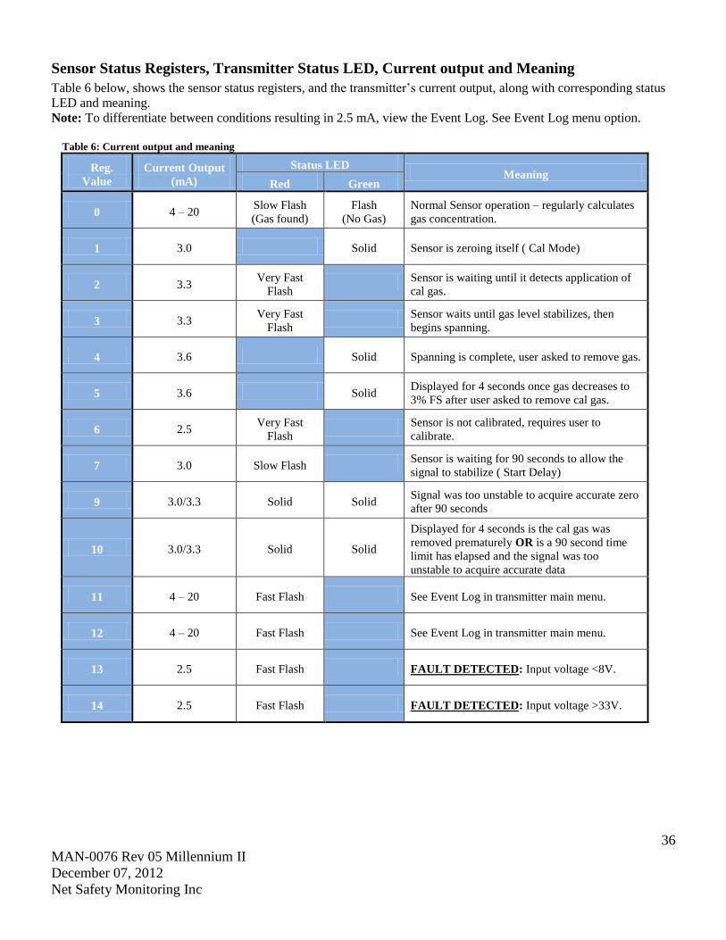
36
MAN-0076 Rev 05 Millennium II
December 07, 2012
Net Safety Monitoring Inc
Sensor Status Registers, Transmitter Status LED, Current output and Meaning
Table 6 below, shows the sensor status registers, and the transmitter’s current output, along with corresponding status
LED and meaning.
Note: To differentiate between conditions resulting in 2.5 mA, view the Event Log. See Event Log menu option.
Table 6: Current output and meaning
Reg.
Value
Current Output
(mA)
Status LED Meaning
Red Green
0 4 – 20 Slow Flash
(Gas found)
Flash
(No Gas)
Normal Sensor operation – regularly calculates
gas concentration.
1 3.0 Solid Sensor is zeroing itself ( Cal Mode)
2 3.3 Very Fast
Flash
Sensor is waiting until it detects application of
cal gas.
3 3.3 Very Fast
Flash
Sensor waits until gas level stabilizes, then
begins spanning.
4 3.6 Solid Spanning is complete, user asked to remove gas.
5 3.6 Solid Displayed for 4 seconds once gas decreases to
3% FS after user asked to remove cal gas.
6 2.5 Very Fast
Flash
Sensor is not calibrated, requires user to
calibrate.
7 3.0 Slow Flash Sensor is waiting for 90 seconds to allow the
signal to stabilize ( Start Delay)
9 3.0/3.3 Solid Solid Signal was too unstable to acquire accurate zero
after 90 seconds
10 3.0/3.3 Solid Solid
Displayed for 4 seconds is the cal gas was
removed prematurely OR is a 90 second time
limit has elapsed and the signal was too
unstable to acquire accurate data
11 4 – 20 Fast Flash See Event Log in transmitter main menu.
12 4 – 20 Fast Flash See Event Log in transmitter main menu.
13 2.5 Fast Flash FAULT DETECTED: Input voltage <8V.
14 2.5 Fast Flash FAULT DETECTED: Input voltage >33V.
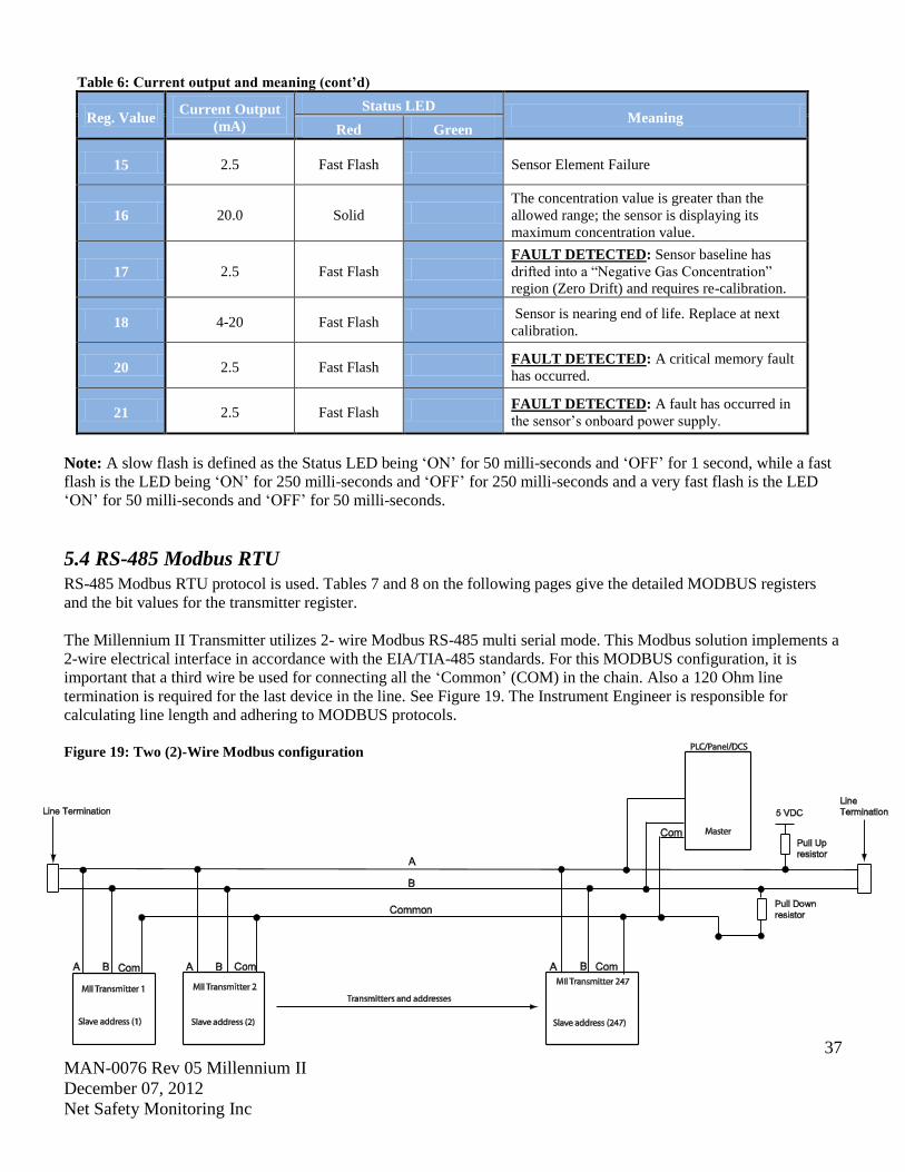
37
MAN-0076 Rev 05 Millennium II
December 07, 2012
Net Safety Monitoring Inc
Table 6: Current output and meaning (cont’d)
Reg. Value Current Output
(mA)
Status LED Meaning
Red Green
15 2.5 Fast Flash Sensor Element Failure
16 20.0 Solid
The concentration value is greater than the
allowed range; the sensor is displaying its
maximum concentration value.
17 2.5 Fast Flash
FAULT DETECTED: Sensor baseline has
drifted into a “Negative Gas Concentration”
region (Zero Drift) and requires re-calibration.
18 4-20 Fast Flash Sensor is nearing end of life. Replace at next
calibration.
20 2.5 Fast Flash FAULT DETECTED: A critical memory fault
has occurred.
21 2.5 Fast Flash FAULT DETECTED: A fault has occurred in
the sensor’s onboard power supply.
Note: A slow flash is defined as the Status LED being ‘ON’ for 50 milli-seconds and ‘OFF’ for 1 second, while a fast
flash is the LED being ‘ON’ for 250 milli-seconds and ‘OFF’ for 250 milli-seconds and a very fast flash is the LED
‘ON’ for 50 milli-seconds and ‘OFF’ for 50 milli-seconds.
5.4 RS-485 Modbus RTU
RS-485 Modbus RTU protocol is used. Tables 7 and 8 on the following pages give the detailed MODBUS registers
and the bit values for the transmitter register.
The Millennium II Transmitter utilizes 2- wire Modbus RS-485 multi serial mode. This Modbus solution implements a
2-wire electrical interface in accordance with the EIA/TIA-485 standards. For this MODBUS configuration, it is
important that a third wire be used for connecting all the ‘Common’ (COM) in the chain. Also a 120 Ohm line
termination is required for the last device in the line. See Figure 19. The Instrument Engineer is responsible for
calculating line length and adhering to MODBUS protocols.
Figure 19: Two (2)-Wire Modbus configuration
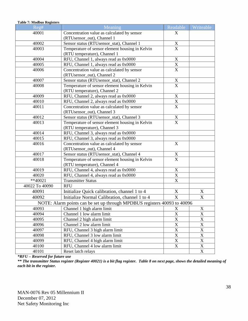
38
MAN-0076 Rev 05 Millennium II
December 07, 2012
Net Safety Monitoring Inc
Table 7: Modbus Registers
Reg# Meaning Readable Writeable 40001 Concentration value as calculated by sensor
(RTUsensor_out), Channel 1
X
40002 Sensor status (RTUsensor_stat), Channel 1 X
40003 Temperature of sensor element housing in Kelvin
(RTU temperature), Channel 1
X
40004 RFU, Channel 1, always read as 0x0000 X
40005 RFU, Channel 1, always read as 0x0000 X
40006 Concentration value as calculated by sensor
(RTUsensor_out), Channel 2
X
40007 Sensor status (RTUsensor_stat), Channel 2 X
40008 Temperature of sensor element housing in Kelvin
(RTU temperature), Channel 2
X
40009 RFU, Channel 2, always read as 0x0000 X
40010 RFU, Channel 2, always read as 0x0000 X
40011 Concentration value as calculated by sensor
(RTUsensor_out), Channel 3
X
40012 Sensor status (RTUsensor_stat), Channel 3 X
40013 Temperature of sensor element housing in Kelvin
(RTU temperature), Channel 3
X
40014 RFU, Channel 3, always read as 0x0000
40015 RFU, Channel 3, always read as 0x0000
40016 Concentration value as calculated by sensor
(RTUsensor_out), Channel 4
X
40017 Sensor status (RTUsensor_stat), Channel 4 X
40018 Temperature of sensor element housing in Kelvin
(RTU temperature), Channel 4
X
40019 RFU, Channel 4, always read as 0x0000 X
40020 RFU, Channel 4, always read as 0x0000 X
**40021 Transmitter Status X
40022 To 40090 RFU
40091 Initialize Quick calibration, channel 1 to 4 X X
40092 Initialize Normal Calibration, channel 1 to 4 X X
NOTE: Alarm points can be set up through MPDBUS registers 40093 to 40096 40093 Channel 1 high alarm limit X X
40094 Channel 1 low alarm limit X X
40095 Channel 2 high alarm limit X X
40096 Channel 2 low alarm limit X X
40097 RFU, Channel 3 high alarm limit X X
40098 RFU, Channel 3 low alarm limit X X
40099 RFU, Channel 4 high alarm limit X X
40100 RFU, Channel 4 low alarm limit X X
40101 Reset latch relays X *RFU – Reserved for future use
** The transmitter Status register (Register 40021) is a bit flag register. Table 8 on next page, shows the detailed meaning of
each bit in the register.
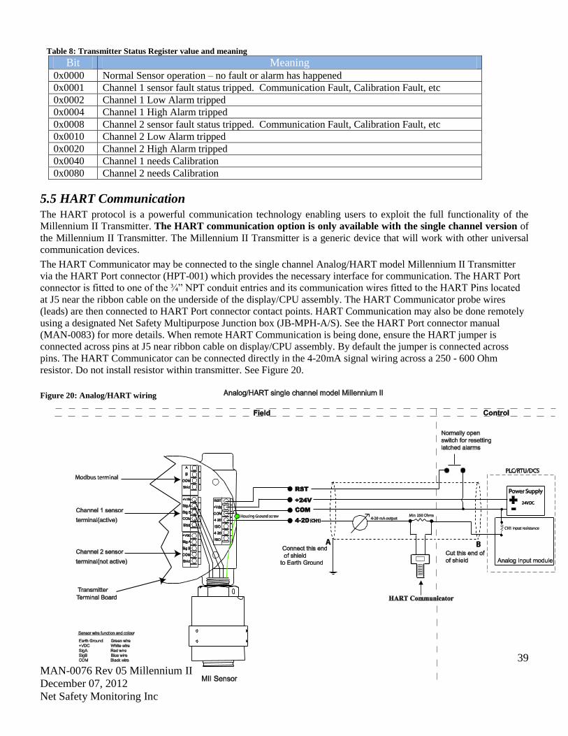
39
MAN-0076 Rev 05 Millennium II
December 07, 2012
Net Safety Monitoring Inc
Table 8: Transmitter Status Register value and meaning
Bit Meaning 0x0000 Normal Sensor operation – no fault or alarm has happened
0x0001 Channel 1 sensor fault status tripped. Communication Fault, Calibration Fault, etc
0x0002 Channel 1 Low Alarm tripped
0x0004 Channel 1 High Alarm tripped
0x0008 Channel 2 sensor fault status tripped. Communication Fault, Calibration Fault, etc
0x0010 Channel 2 Low Alarm tripped
0x0020 Channel 2 High Alarm tripped
0x0040 Channel 1 needs Calibration
0x0080 Channel 2 needs Calibration
5.5 HART Communication
The HART protocol is a powerful communication technology enabling users to exploit the full functionality of the
Millennium II Transmitter. The HART communication option is only available with the single channel version of
the Millennium II Transmitter. The Millennium II Transmitter is a generic device that will work with other universal
communication devices.
The HART Communicator may be connected to the single channel Analog/HART model Millennium II Transmitter
via the HART Port connector (HPT-001) which provides the necessary interface for communication. The HART Port
connector is fitted to one of the ¾” NPT conduit entries and its communication wires fitted to the HART Pins located
at J5 near the ribbon cable on the underside of the display/CPU assembly. The HART Communicator probe wires
(leads) are then connected to HART Port connector contact points. HART Communication may also be done remotely
using a designated Net Safety Multipurpose Junction box (JB-MPH-A/S). See the HART Port connector manual
(MAN-0083) for more details. When remote HART Communication is being done, ensure the HART jumper is
connected across pins at J5 near ribbon cable on display/CPU assembly. By default the jumper is connected across
pins. The HART Communicator can be connected directly in the 4-20mA signal wiring across a 250 - 600 Ohm
resistor. Do not install resistor within transmitter. See Figure 20.
Figure 20: Analog/HART wiring
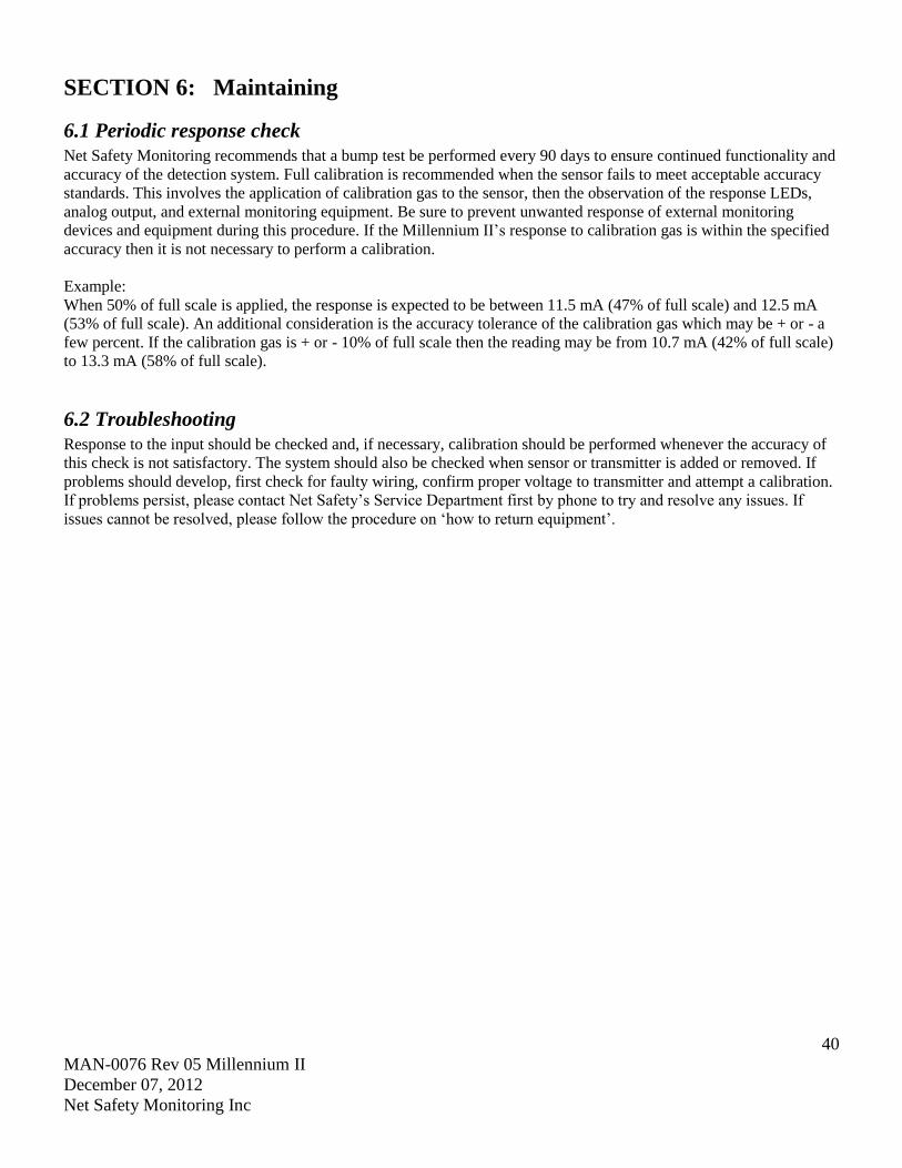
40
MAN-0076 Rev 05 Millennium II
December 07, 2012
Net Safety Monitoring Inc
SECTION 6: Maintaining
6.1 Periodic response check Net Safety Monitoring recommends that a bump test be performed every 90 days to ensure continued functionality and
accuracy of the detection system. Full calibration is recommended when the sensor fails to meet acceptable accuracy
standards. This involves the application of calibration gas to the sensor, then the observation of the response LEDs,
analog output, and external monitoring equipment. Be sure to prevent unwanted response of external monitoring
devices and equipment during this procedure. If the Millennium II’s response to calibration gas is within the specified
accuracy then it is not necessary to perform a calibration.
Example:
When 50% of full scale is applied, the response is expected to be between 11.5 mA (47% of full scale) and 12.5 mA
(53% of full scale). An additional consideration is the accuracy tolerance of the calibration gas which may be + or - a
few percent. If the calibration gas is + or - 10% of full scale then the reading may be from 10.7 mA (42% of full scale)
to 13.3 mA (58% of full scale).
6.2 Troubleshooting Response to the input should be checked and, if necessary, calibration should be performed whenever the accuracy of
this check is not satisfactory. The system should also be checked when sensor or transmitter is added or removed. If
problems should develop, first check for faulty wiring, confirm proper voltage to transmitter and attempt a calibration.
If problems persist, please contact Net Safety’s Service Department first by phone to try and resolve any issues. If
issues cannot be resolved, please follow the procedure on ‘how to return equipment’.

41
MAN-0076 Rev 05 Millennium II
December 07, 2012
Net Safety Monitoring Inc
6.3 Storage
The transmitter and its electronic components/parts should be stored in locations free from dust and
moisture. The storage temperature should be well within the limits of the certified temperatures. See
Appendix C for certified temperatures.
6.4 Spare Parts /Accessories
Table 9: Spare Parts Numbering
Net Safety Part Number Description
CCS-1 Calibration Cup/Splash Guard
DSC-1 Dust Filter Assembly
IPF-001 IP66/67 Hydrophobic Filter
JB-MPD-A or JB-MPD-S Separation Kit
TX-M21-A Single channel transmitter w/analog output
TX-M21-AR Single channel transmitter w/analog & mech. relay outputs
TX-M21-ARS Single channel transmitter w/analog & solid state relay output
TX-M21-AD Single channel transmitter w/analog &digital Modbus outputs
TX-M21-ARD Single channel transmitter w/analog , mech. relay &digital Modbus output
TX-M21-AH Single channel transmitter w/ analog / Hart communication output
TX-M21-AHR Single channel transmitter w/analog /Hart communication & relay output
TX-M22-A Dual channel transmitter w/analog output
TX-M22-AR Dual channel transmitter w/analog and mech. relay output
TX-M22-ARS Dual channel transmitter w/analog & solid state relay output
TX-M22-AD Dual channel transmitter w/analog & digital Modbus output
TX-M22-ARD Dual channel transmitter w/analog, relay & digital Modbus output

42
MAN-0076 Rev 05 Millennium II
December 07, 2012
Net Safety Monitoring Inc
6.5 How to Return Equipment
A Material Return Authorization number is required in order to return equipment. Please contact Net Safety
Monitoring at (403) 219-0688, before returning equipment or consult our Service Department to possibly avoid
returning equipment.
If you are required to return equipment, include the following information:
1. A Material Return Authorization number (provided over the phone to you by Net Safety).
2. A detailed description of the problem. The more specific you are regarding the problem, the quicker our
Service Department can determine and correct the problem.
3. A company name, contact name and telephone number.
4. A purchase order, from your company, authorizing repairs or request for quote.
5. Ship all equipment, prepaid to: Net Safety Monitoring Inc.,
2721 Hopewell Place NE,
Calgary, Alberta, Canada, T1Y 7J7
6. Mark all packages: RETURN for REPAIR.
7. Waybills, for shipment outside Canada, must state: Equipment being returned for repair
All charges to be billed to the sender
Ensure a duplicate copy of the packing slip is enclosed inside the box indicating item 1 – 4 along with the courier
and account number for returning the goods.
Pack items to protect them from damage and use anti-static bags or Aluminum-backed cardboard as protection
from electro-static discharge.
ALL equipment must be shipped prepaid. Collect shipments will not be accepted.

43
MAN-0076 Rev 05 Millennium II
December 07, 2012
Net Safety Monitoring Inc
Appendix
Appendix A: ELECTROSTATIC SENSITIVE DEVICE (ESD) Definition: Electrostatic discharge (ESD) is the transfer, between bodies, of an electrostatic charge caused by direct
contact or induced by an electrostatic field.
The most common cause of ESD is physical contact. Touching an object can cause a discharge of electrostatic
energy—ESD! If the charge is sufficient and occurs near electronic components, it can damage or destroy those
components.
In some cases, damage is instantaneous and an immediate malfunction occurs. However, symptoms are not always
immediate—performance may be marginal or seemingly normal for an indefinite period of time, followed by a sudden
failure.
To eliminate potential ESD damage, review the following guidelines:
• Handle boards by metal shields—taking care not to touch electronic components
• Wear grounded wrist or foot straps, or ESD shoes or heel grounders to dissipate unwanted static energy
• Prior to handling boards, dispel any charge in your body or equipment
• Ensure components are transported and stored in static safe packaging
• When returning boards, carefully package in the original carton and static protective wrapping
• Ensure ALL personnel are educated and trained in ESD Control Procedures
In general, exercise accepted and proven precautions normally observed when handling electrostatic sensitive devices.
A warning label is placed on the packaging, identifying product using electrostatic sensitive semiconductor devices.
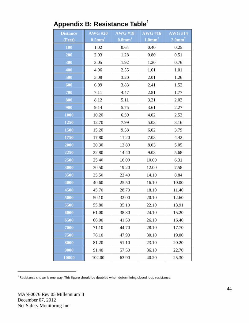
44
MAN-0076 Rev 05 Millennium II
December 07, 2012
Net Safety Monitoring Inc
Appendix B: Resistance Table1
Distance
(Feet)
AWG #20
0.5mm2
AWG #18
0.8mm2
AWG #16
1.0mm2
AWG #14
2.0mm2
100 1.02 0.64 0.40 0.25
200 2.03 1.28 0.80 0.51
300 3.05 1.92 1.20 0.76
400 4.06 2.55 1.61 1.01
500 5.08 3.20 2.01 1.26
600 6.09 3.83 2.41 1.52
700 7.11 4.47 2.81 1.77
800 8.12 5.11 3.21 2.02
900 9.14 5.75 3.61 2.27
1000 10.20 6.39 4.02 2.53
1250 12.70 7.99 5.03 3.16
1500 15.20 9.58 6.02 3.79
1750 17.80 11.20 7.03 4.42
2000 20.30 12.80 8.03 5.05
2250 22.80 14.40 9.03 5.68
2500 25.40 16.00 10.00 6.31
3000 30.50 19.20 12.00 7.58
3500 35.50 22.40 14.10 8.84
4000 40.60 25.50 16.10 10.00
4500 45.70 28.70 18.10 11.40
5000 50.10 32.00 20.10 12.60
5500 55.80 35.10 22.10 13.91
6000 61.00 38.30 24.10 15.20
6500 66.00 41.50 26.10 16.40
7000 71.10 44.70 28.10 17.70
7500 76.10 47.90 30.10 19.00
8000 81.20 51.10 23.10 20.20
9000 91.40 57.50 36.10 22.70
10000 102.00 63.90 40.20 25.30
1 Resistance shown is one way. This figure should be doubled when determining closed loop resistance.
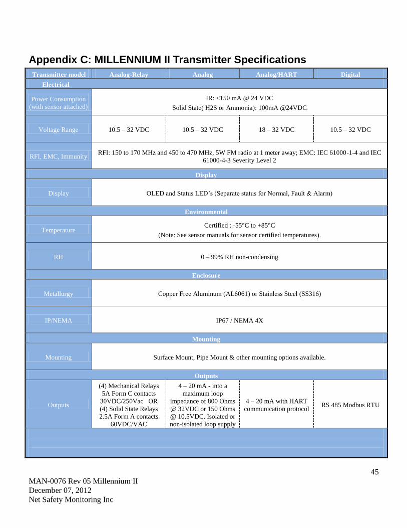
45
MAN-0076 Rev 05 Millennium II
December 07, 2012
Net Safety Monitoring Inc
Appendix C: MILLENNIUM II Transmitter Specifications
Transmitter model Analog-Relay Analog Analog/HART Digital
Electrical
Power Consumption
(with sensor attached)
IR: <150 mA @ 24 VDC
Solid State( H2S or Ammonia): 100mA @24VDC
Voltage Range 10.5 – 32 VDC 10.5 – 32 VDC 18 – 32 VDC 10.5 – 32 VDC
RFI, EMC, Immunity RFI: 150 to 170 MHz and 450 to 470 MHz, 5W FM radio at 1 meter away; EMC: IEC 61000-1-4 and IEC
61000-4-3 Severity Level 2
Display
Display OLED and Status LED’s (Separate status for Normal, Fault & Alarm)
Environmental
Temperature Certified : -55°C to +85°C
(Note: See sensor manuals for sensor certified temperatures).
RH 0 – 99% RH non-condensing
Enclosure
Metallurgy Copper Free Aluminum (AL6061) or Stainless Steel (SS316)
IP/NEMA IP67 / NEMA 4X
Mounting
Mounting Surface Mount, Pipe Mount & other mounting options available.
Outputs
Outputs
(4) Mechanical Relays
5A Form C contacts
30VDC/250Vac OR
(4) Solid State Relays
2.5A Form A contacts
60VDC/VAC
4 – 20 mA - into a
maximum loop
impedance of 800 Ohms
@ 32VDC or 150 Ohms
@ 10.5VDC. Isolated or
non-isolated loop supply
4 – 20 mA with HART
communication protocol RS 485 Modbus RTU
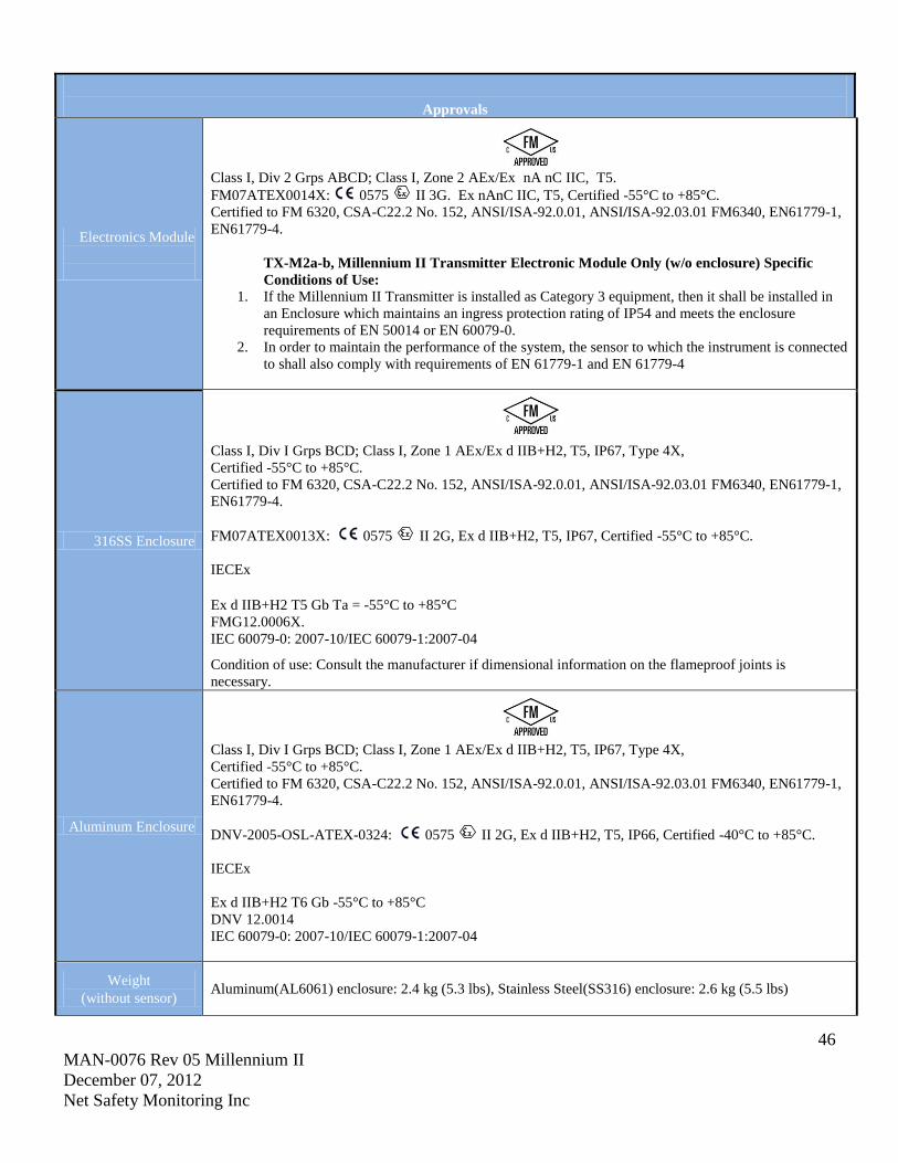
46
MAN-0076 Rev 05 Millennium II
December 07, 2012
Net Safety Monitoring Inc
Approvals
Electronics Module
Class I, Div 2 Grps ABCD; Class I, Zone 2 AEx/Ex nA nC IIC, T5.
FM07ATEX0014X: 0575 II 3G. Ex nAnC IIC, T5, Certified -55°C to +85°C.
Certified to FM 6320, CSA-C22.2 No. 152, ANSI/ISA-92.0.01, ANSI/ISA-92.03.01 FM6340, EN61779-1,
EN61779-4.
TX-M2a-b, Millennium II Transmitter Electronic Module Only (w/o enclosure) Specific
Conditions of Use: 1. If the Millennium II Transmitter is installed as Category 3 equipment, then it shall be installed in
an Enclosure which maintains an ingress protection rating of IP54 and meets the enclosure
requirements of EN 50014 or EN 60079-0.
2. In order to maintain the performance of the system, the sensor to which the instrument is connected
to shall also comply with requirements of EN 61779-1 and EN 61779-4
316SS Enclosure
Class I, Div I Grps BCD; Class I, Zone 1 AEx/Ex d IIB+H2, T5, IP67, Type 4X,
Certified -55°C to +85°C.
Certified to FM 6320, CSA-C22.2 No. 152, ANSI/ISA-92.0.01, ANSI/ISA-92.03.01 FM6340, EN61779-1,
EN61779-4.
FM07ATEX0013X: 0575 II 2G, Ex d IIB+H2, T5, IP67, Certified -55°C to +85°C.
IECEx
Ex d IIB+H2 T5 Gb Ta = -55°C to +85°C
FMG12.0006X.
IEC 60079-0: 2007-10/IEC 60079-1:2007-04
Condition of use: Consult the manufacturer if dimensional information on the flameproof joints is
necessary.
Aluminum Enclosure
Class I, Div I Grps BCD; Class I, Zone 1 AEx/Ex d IIB+H2, T5, IP67, Type 4X,
Certified -55°C to +85°C.
Certified to FM 6320, CSA-C22.2 No. 152, ANSI/ISA-92.0.01, ANSI/ISA-92.03.01 FM6340, EN61779-1,
EN61779-4.
DNV-2005-OSL-ATEX-0324: 0575 II 2G, Ex d IIB+H2, T5, IP66, Certified -40°C to +85°C.
IECEx
Ex d IIB+H2 T6 Gb -55°C to +85°C
DNV 12.0014
IEC 60079-0: 2007-10/IEC 60079-1:2007-04
Weight
(without sensor) Aluminum(AL6061) enclosure: 2.4 kg (5.3 lbs), Stainless Steel(SS316) enclosure: 2.6 kg (5.5 lbs)

47
MAN-0076 Rev 05 Millennium II
December 07, 2012
Net Safety Monitoring Inc
Net Safety Monitoring Inc.
2721 Hopewell Place NE, Calgary, AB Canada T1Y 7J7
1-866-FIREGAS (347-3427) | ph. (403) 219-0688 | fx. (403) 219-0694
http://www.net-safety.com | Email: [email protected]
PRODUCT SERVICES CONTACT INFORMATION
Telephone [ 8am - 5pm MDT ]: (403) 769-6074 | (403) 717-8219
Fax: (403) 219-0694 Email: [email protected]
http://www.net-safety.com/service/product_services.html