Embed Size (px)
Citation preview
NIE Standard Efficiency and IE2/IE3 High EfficiencyVariable Speed and Fixed Speed
Frame Size 71 to 160Power 0.25 to 15 kW
IMfinity®
FFB Brake Motors
2 LS FFB - LSES FFB Brake Motors - 5329 en - 2015.10 / b
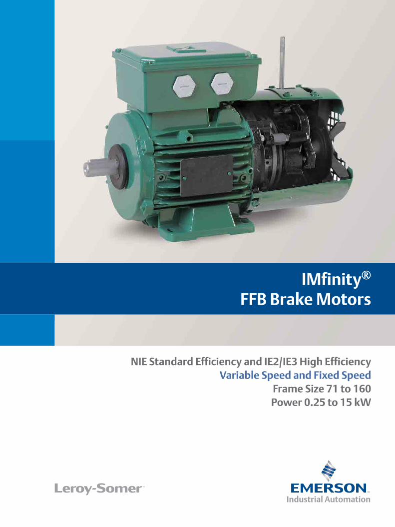
LS FFB - LSES FFB Brake Motors
Brake Ranges
FFB Brake Motors Offer
EnvironmentNormal Dust-protected
CommissioningFFB
brochureFFB
catalogFFB
installationFFB
maintenance
II3D II2D
5281 5329 5286 5287 Pending
Fixed speed
4-pole brakes
90 kW FCPL
65 --> 2400 N.m
15 kWFFB
11 kW9 kW
4.5 --> 200 N.m0.37 kW
FMD0.25 kW0.06 kW 3.5 N.m
Fr. size --> 56 --> 71 71 --> 160 160 --> 280
2, 4, 6P0.25 --> 15 kW
2.5 --> 120 N.mPlease consult LSUT: Translation
UG: General
NORMAL
PROTECTED ATEX
2, 4, 6P0.25 --> 15 kW
4P0.25 --> 15 kW
LS, LS IFT/NIELSES IFT IE2/IE3
Please consult LS
Please consult LS21
22
ZONE
4P0.25 --> 15 kW
2,400 rpm4.8 --> 36 kW
LS, LS IFT/NIELSES IFT IE2/IE3
LSRPMPlease consult LSSYNCHRONOUS
ASYNCHRONOUS
SOLUTION
FIXED
SPEED
BRAKE MOTORS ENVIRONMENT
4P0.25 --> 11 kW
LS, LS IFT/NIELSES IFT IE2/IE3
Please consult LS
CABINET-MOUNTED
INTEGRATED
SOLUTION
4P0.25 --> 15 kW
4P0.75 --> 15 kW
LS, LS IFT/NIELSES IFT IE2/IE3
FLSES IFT IE2/IE3Please consult LSCAST IRON
ALUMINUM
FRAME
APPLICATION UL: Hoisting
VARIABLE
VMA
INTRODUCTION
All brake motors in this catalogue that don‘t fall within the scope of regulation 640/2009 in directive 2009/125/EC can be offered for sale* on the European Union market.* according to the definition relating to application of European Union regulations concerning products.
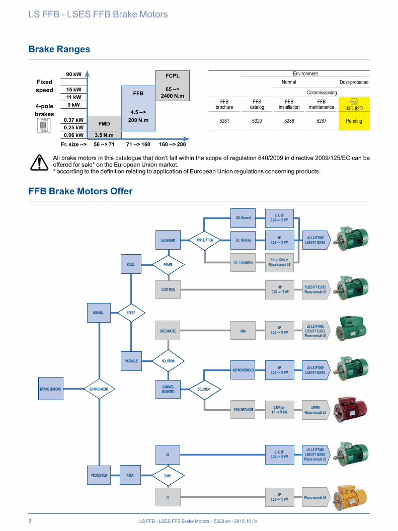
3LS FFB - LSES FFB Brake Motors - 5329 en - 2015.10 / b
LS FFB - LSES FFB Brake Motors
Associated Gearbox Ranges
Associated Drive Ranges
LS IFT/NIE,LSES IFT/IE2/IE3
Variable speed
110 kW DIGISTART UNIDRIVE M POWERDRIVE75 kW --> M700 MD2M45 kW --> M400--> 22 kW M600 FX--> 11 kW M300 --> 11 kW VMA T
7.5 kW PROXIDRIVE F300 7.5 kW VMA TL
2.2 kW --> M100 M200 2.2 kW -->1.1 kW 1.5 kW VMA M0.37 kW 0.37 kW -->0.25 kW 0.25 kW --> VARMECA
Starter Cabinet-mounted variable speed Built-in variable speed
AXIAL
PERPENDICULAR
HELICAL GEARS
WORM GEARS
SOLID SHAFT
HOLLOW SHAFTSOLID SHAFT
HOLLOW SHAFTSOLID SHAFT
HOLLOW SHAFTSOLID SHAFT
--> 110 kW--> 16,000 N.m
--> 110 kW--> 14,500 N.m
--> 9 kW--> 1,500 N.m
--> 132 kW--> 23,000 N.m
COMPABLOC
MANUBLOC
MULTIBLOC
ORTHOBLOC
DIRECT DRIVE
LOW
VERY HIGH
REVERSIBILITY
FOOT OR FLANGE
MOUNTING
SHAFT
ELECTRO-MECHANICAL ASSEMBLIES
HELICAL BEVEL GEARS
HELICAL GEARS
FOOT OR FLANGE
OUTPUT
4 LS FFB - LSES FFB Brake Motors - 5329 en - 2015.10 / b
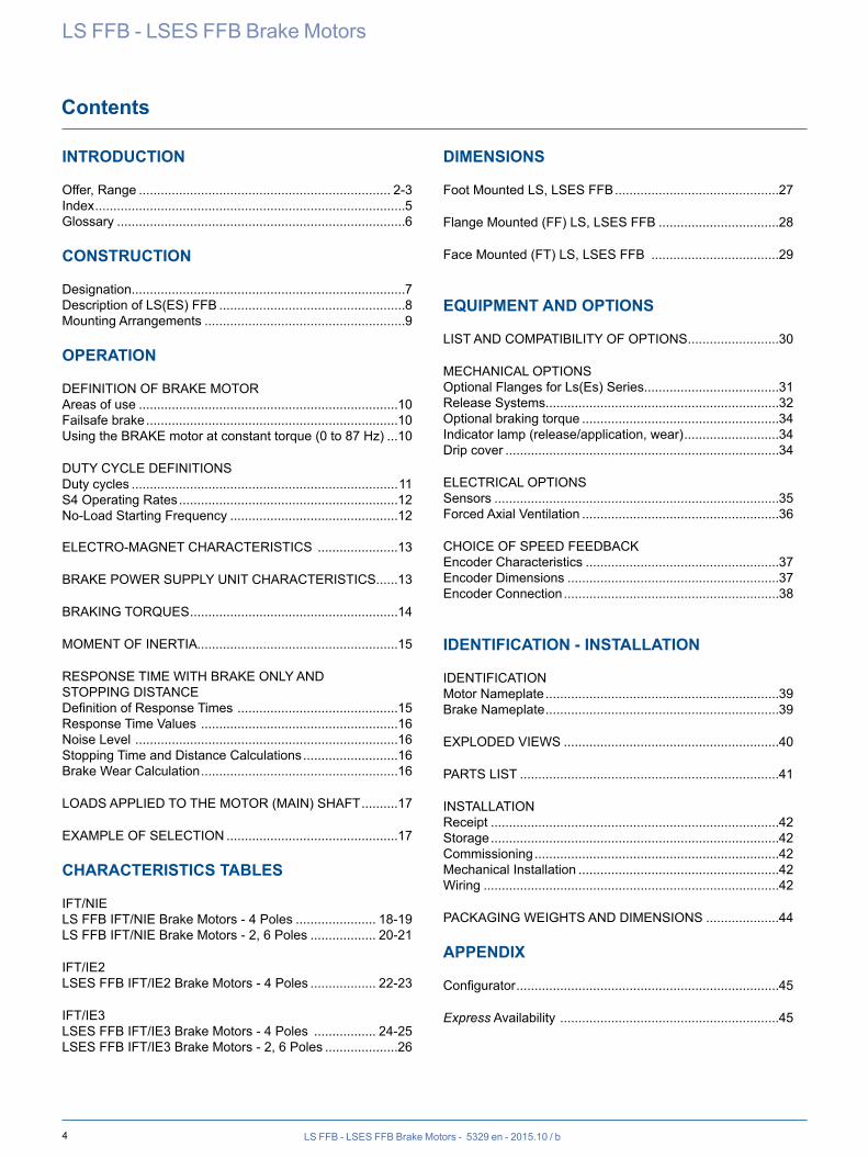
Contents
LS FFB - LSES FFB Brake Motors
INTRODUCTION
Offer, Range ..................................................................... 2-3Index .....................................................................................5Glossary ...............................................................................6
CONSTRUCTION
Designation...........................................................................7Description of LS(ES) FFB ...................................................8Mounting Arrangements .......................................................9
OPERATION
DEFINITION OF BRAKE MOTORAreas of use .......................................................................10Failsafe brake .....................................................................10Using the BRAKE motor at constant torque (0 to 87 Hz) ...10
DUTY CYCLE DEFINITIONSDuty cycles .........................................................................11S4 Operating Rates ............................................................12No-Load Starting Frequency ..............................................12
ELECTRO-MAGNET CHARACTERISTICS ......................13
BRAKE POWER SUPPLY UNIT CHARACTERISTICS......13
BRAKING TORQUES .........................................................14
MOMENT OF INERTIA .......................................................15
RESPONSE TIME WITH BRAKE ONLY AND STOPPING DISTANCEDefinition of Response Times ............................................15Response Time Values ......................................................16Noise Level ........................................................................16Stopping Time and Distance Calculations ..........................16Brake Wear Calculation ......................................................16
LOADS APPLIED TO THE MOTOR (MAIN) SHAFT ..........17
EXAMPLE OF SELECTION ...............................................17
CHARACTERISTICS TABLES
IFT/NIELS FFB IFT/NIE Brake Motors - 4 Poles ...................... 18-19LS FFB IFT/NIE Brake Motors - 2, 6 Poles .................. 20-21
IFT/IE2LSES FFB IFT/IE2 Brake Motors - 4 Poles .................. 22-23
IFT/IE3LSES FFB IFT/IE3 Brake Motors - 4 Poles ................. 24-25LSES FFB IFT/IE3 Brake Motors - 2, 6 Poles ....................26
DIMENSIONS
Foot Mounted LS, LSES FFB .............................................27
Flange Mounted (FF) LS, LSES FFB .................................28
Face Mounted (FT) LS, LSES FFB ...................................29
EQUIPMENT AND OPTIONS
LIST AND COMPATIBILITY OF OPTIONS .........................30
MECHANICAL OPTIONSOptional Flanges for Ls(Es) Series.....................................31Release Systems................................................................32Optional braking torque ......................................................34Indicator lamp (release/application, wear) ..........................34Drip cover ...........................................................................34
ELECTRICAL OPTIONSSensors ..............................................................................35Forced Axial Ventilation ......................................................36
CHOICE OF SPEED FEEDBACKEncoder Characteristics .....................................................37Encoder Dimensions ..........................................................37Encoder Connection ...........................................................38
IDENTIFICATION - INSTALLATION
IDENTIFICATIONMotor Nameplate ................................................................39Brake Nameplate ................................................................39
EXPLODED VIEWS ...........................................................40
PARTS LIST .......................................................................41
INSTALLATIONReceipt ...............................................................................42Storage ...............................................................................42Commissioning ...................................................................42Mechanical Installation .......................................................42Wiring .................................................................................42
PACKAGING WEIGHTS AND DIMENSIONS ....................44
APPENDIX
Configurator ........................................................................45
Express Availability ............................................................45
5LS FFB - LSES FFB Brake Motors - 5329 en - 2015.10 / b
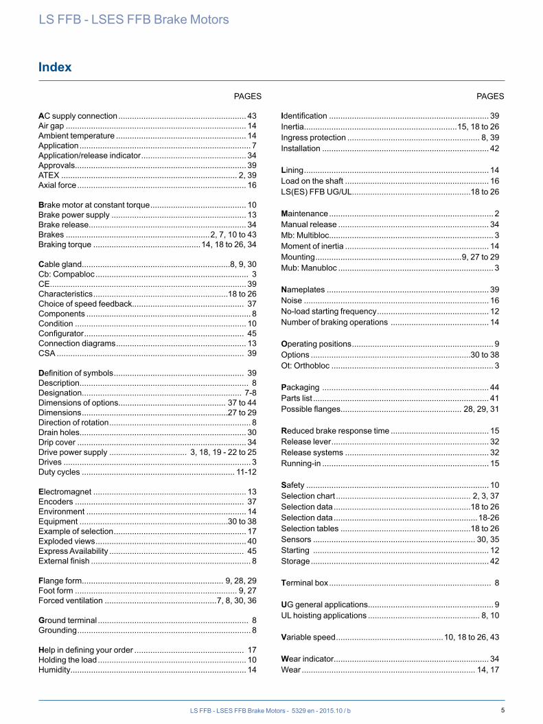
Index
LS FFB - LSES FFB Brake Motors
AC supply connection ........................................................ 43Air gap ............................................................................... 14Ambient temperature ......................................................... 14Application ........................................................................... 7Application/release indicator .............................................. 34Approvals........................................................................... 39ATEX ............................................................................. 2, 39Axial force .......................................................................... 16
Brake motor at constant torque .......................................... 10Brake power supply ........................................................... 13Brake release..................................................................... 34Brakes ...............................................................2, 7, 10 to 43Braking torque ...............................................14, 18 to 26, 34
Cable gland.................................................................8, 9, 30Cb: Compabloc ................................................................... 3CE...................................................................................... 39Characteristics ...........................................................18 to 26Choice of speed feedback................................................. 37Components ........................................................................ 8Condition ........................................................................... 10Configurator ...................................................................... 45Connection diagrams ......................................................... 13CSA .................................................................................. 39
Definition of symbols ......................................................... 39Description.......................................................................... 8Designation...................................................................... 7-8Dimensions of options............................................... 37 to 44Dimensions ................................................................27 to 29Direction of rotation .............................................................. 8Drain holes......................................................................... 30Drip cover .......................................................................... 34Drive power supply .................................. 3, 18, 19 - 22 to 25Drives .................................................................................. 3Duty cycles ................................................................... 11-12
Electromagnet ................................................................... 13Encoders .......................................................................... 37Environment ...................................................................... 14Equipment .................................................................30 to 38Example of selection .......................................................... 17Exploded views .................................................................. 40Express Availability ........................................................... 45External finish ...................................................................... 8
Flange form.............................................................. 9, 28, 29Foot form ....................................................................... 9, 27Forced ventilation .................................................7, 8, 30, 36
Ground terminal .................................................................. 8Grounding ............................................................................ 8
Help in defining your order ................................................ 17Holding the load ................................................................. 10Humidity............................................................................. 14
Identification ...................................................................... 39Inertia...................................................................15, 18 to 26Ingress protection .......................................................... 8, 39Installation ......................................................................... 42
Lining ................................................................................. 14Load on the shaft ............................................................... 16LS(ES) FFB UG/UL ....................................................18 to 26
Maintenance ........................................................................ 2Manual release .................................................................. 34Mb: Multibloc........................................................................ 3Moment of inertia ............................................................... 14Mounting ................................................................9, 27 to 29Mub: Manubloc .................................................................... 3
Nameplates ....................................................................... 39Noise ................................................................................. 16No-load starting frequency ................................................. 12Number of braking operations ........................................... 14
Operating positions .............................................................. 9Options ......................................................................30 to 38Ot: Orthobloc ....................................................................... 3
Packaging ......................................................................... 44Parts list ............................................................................. 41Possible flanges..................................................... 28, 29, 31
Reduced brake response time ........................................... 15Release lever ..................................................................... 32Release systems ............................................................... 32Running-in ......................................................................... 15
Safety ................................................................................ 10Selection chart ........................................................... 2, 3, 37Selection data ............................................................18 to 26Selection data ...............................................................18-26Selection tables .........................................................18 to 26Sensors ....................................................................... 30, 35Starting ............................................................................. 12Storage .............................................................................. 42
Terminal box ....................................................................... 8
UG general applications....................................................... 9UL hoisting applications ................................................. 8, 10
Variable speed ...............................................10, 18 to 26, 43
Wear indicator.................................................................... 34Wear ............................................................................ 14, 17
PAGES PAGES
6 LS FFB - LSES FFB Brake Motors - 5329 en - 2015.10 / b
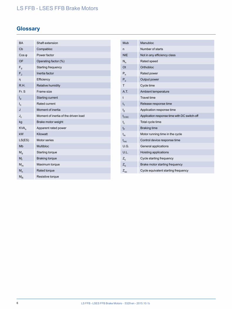
Glossary
LS FFB - LSES FFB Brake Motors
BA Shaft extension
Cb Compabloc
Cos φ Power factor
OF Operating factor (%)
Fd Starting frequency
FJ Inertia factor
η Efficiency
R.H. Relative humidity
Fr. S Frame size
Id Starting current
In Rated current
J Moment of inertia
Jc Moment of inertia of the driven load
kg Brake motor weight
KVAn Apparent rated power
kW Kilowatt
LS(ES) Motor series
Mb Multibloc
Md Starting torque
Mf Braking torque
Mm Maximum torque
Mn Rated torque
MR Resistive torque
Mub Manubloc
n Number of starts
NIE Not in any efficiency class
Nn Rated speed
Ot Orthobloc
Pn Rated power
Pu Output power
T Cycle time
A.T. Ambient temperature
t Travel time
t1 Release response time
t2 Application response time
t2 DC Application response time with DC switch-off
tc Total cycle time
tF Braking time
tm Motor running time in the cycle
troc Control device response time
U.G. General applications
U.L. Hoisting applications
Zc Cycle starting frequency
Zo Brake motor starting frequency
Zoc Cycle equivalent starting frequency
7LS FFB - LSES FFB Brake Motors - 5329 en - 2015.10 / b
LS FFB - LSES FFB Brake Motors
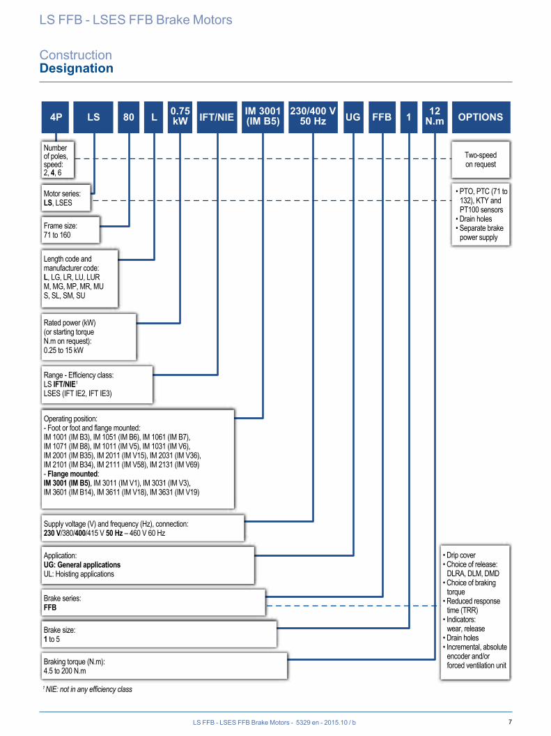
ConstructionDesignation
4P LS 80 L 0.75kW FFB 1 12
N.m OPTIONSIM 3001(IM B5)IFT/NIE UG
Number of poles,speed:2, 4, 6
Two-speed on request
• PTO, PTC (71 to 132), KTY and PT100 sensors
• Drain holes• Separate brake
power supply
• Drip cover• Choice of release:
DLRA, DLM, DMD• Choice of braking
torque• Reduced response
time (TRR)• Indicators:
wear, release• Drain holes• Incremental, absolute
encoder and/or forced ventilation unit
Motor series:LS, LSES
Frame size:71 to 160
Supply voltage (V) and frequency (Hz), connection:230 V/380/400/415 V 50 Hz – 460 V 60 Hz
Brake series:FFB
Brake size:1 to 5
Braking torque (N.m):4.5 to 200 N.m
Length code and manufacturer code:L, LG, LR, LU, LURM, MG, MP, MR, MUS, SL, SM, SU
Rated power (kW)(or starting torque N.m on request):0.25 to 15 kW
Range - Efficiency class:LS IFT/NIE1
LSES (IFT IE2, IFT IE3)
Application:UG: General applicationsUL: Hoisting applications
Operating position:- Foot or foot and flange mounted:IM 1001 (IM B3), IM 1051 (IM B6), IM 1061 (IM B7),IM 1071 (IM B8), IM 1011 (IM V5), IM 1031 (IM V6),IM 2001 (IM B35), IM 2011 (IM V15), IM 2031 (IM V36),IM 2101 (IM B34), IM 2111 (IM V58), IM 2131 (IM V69)- Flange mounted:IM 3001 (IM B5), IM 3011 (IM V1), IM 3031 (IM V3),IM 3601 (IM B14), IM 3611 (IM V18), IM 3631 (IM V19)
230/400 V50 Hz
1 NIE: not in any efficiency class
8 LS FFB - LSES FFB Brake Motors - 5329 en - 2015.10 / b
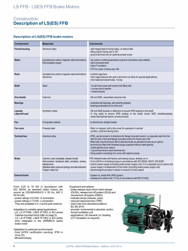
Description of LS(ES) FFB brake motors
Component Materials Comments
Finned housing Aluminum alloy - with integral feet (4 fixing holes), or without feet- lifting ring for frame size ≥ 100 - ground terminal with an optional jumper screw
Stator Insulated low-carbon magnetic steel laminationsElectroplated copper
- low carbon content guarantees long-term lamination pack stability- semi-enclosed slots- class F insulation- PTC for motor ≥ frame size 160
Rotor Insulated low-carbon magnetic steel laminationsAluminum
- inclined cage bars- rotor cage pressure die-cast in aluminum (or alloy for special applications)- rotor balanced dynamically, 1/2 key
Shaft Steel - for all frame sizes with centre hole fitted with:• a screw and a washer• closed keyway
End shields Cast iron - DE and NDE, assembled using tie rods
Bearings - protected ball bearings, permanently greased- bearings preloaded at non drive end
LipsealsLabyrinth seal
Synthetic rubber - DE and NDE lipseals or deflectors to ensure IP55 sealing on the shaft- O ring seals to ensure IP55 sealing of the brake (motor NDE shield/backplate, brake disk/splined sleeve, armature/yoke)
Fan Composite material - bi-directional: straight blades
Fan cover Pressed steel - fitted, on request, with a drip cover for operation in vertical position, shaft end facing down
Terminal box Aluminum alloy - IP55, can be turned in 4 directions for flange mounted version, on opposite side from the feet for foot or foot and flange mounted version for frame size ≥ 80
- fitted with a terminal block with 6 steel terminals as standard (brass as an option)- terminal box fitted with threaded plugs (supplied without cable glands) (cable glands as an option)
- 1 ground terminal in each terminal box- fixing system consisting of a cover with captive screws
Brake Cast iron: yoke, backplate, release handleAnti-corrosion hardened steel: armature, screws, release leverStainless steel: pressure springs, encoder extensionCopper: brake coil
FFB: failsafe brake with factory-set braking torque, already run in• 4.5 to 200 N.m of braking torque in accordance with IEC 60034, 60072, EN 50281• built-in power supply (including brake power supply unit); if it is separate (as an option) the
power supply is independent of the motor (including brake power supply unit)• electromagnet encased in plastic to ensure it is fully sealed
External finish - System Ia, shade RAL 6000 (green)- resistance to saline mist: 72 hrs (in accordance with NFX 41002)
From 0.25 to 15 kW in accordance with IEC 60034, as standard brake motors are wound as 230/380/400/415 V 50 Hz, 460 V 60 Hz with:- power ratings ≤ 5.5 kW:
Y
connection- power ratings ≥ 7.5 kW: ∆ connection They are available in 2, 4 and 6-pole versions.
Adaptation to variable speed applications:- LS, LS IFT/NIE, LSES IFT/IE2 or IE3 series Cabinet-mounted drive (offer on page 3):
- LS, LS IFT/NIE, LSES IFT/IE2 or IE3 series drive integrated in the VARMECA series brake motor
Adaptation to particular environments:- Dust (ATEX certification pending, IP55 in zone 22)
- Mineral industry
Equipment and options:- brake release (auto-return hand release (DLRA), release lock off system (DLM) and remote lock off system (DMD))
- indicator lamps (release, wear)- reduced response time (TRR)- drain hole (non-standard positions: B3, B5, B14)
- encoder: incremental or absolute, and/or forced ventilation unit
- applications: UG General, UL Hoisting (UT Translation on request)
LS FFB - LSES FFB Brake Motors
ConstructionDescription of LS(ES) FFB
9
IM 3001 (IM B5) IM 3011 (IM V1) IM 3031 (IM V3) IM 2001 (IM B35) IM 2011 (IM V15) IM 2031 (IM V36)
IM 1001 (IM B3) IM 1051 (IM B6) IM 1061 (IM B7) IM 1071 (IM B8) IM 1011 (IM V5) IM 1031 (IM V6)
IM 3601 (IM B14) IM 3611 (IM V18) IM 3631 (IM V19) IM 2101 (IM B34) IM 2111 (IM V58) IM 2131 (IM V69)
LS FFB - LSES FFB Brake Motors - 5329 en - 2015.10 / b
LS FFB - LSES FFB Brake Motors
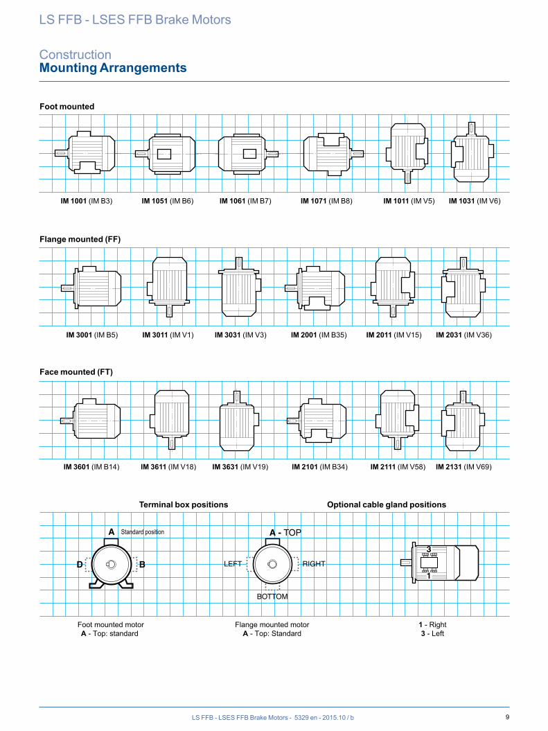
ConstructionMounting Arrangements
Foot mounted
Flange mounted (FF)
Face mounted (FT)
Terminal box positions Optional cable gland positions
Foot mounted motorA - Top: standard
Flange mounted motorA - Top: Standard
1 - Right3 - Left
A - TOP
BOTTOM
RIGHTLEFT
1
3
A
BD
Standard position
10 LS FFB - LSES FFB Brake Motors - 5329 en - 2015.10 / b
The brake motor combines, in a single electromechanical assembly- a motor: rotor + stator which forms the
drive mechanism- a control device: electromagnet +
springs which apply or release the brake- friction: lining + mating surface which
provide the braking action
Areas of useIntermittent duty: a mechanical device driven by a motor on its own takes a long time to stop if there is little friction. The brake motor ensures shorter, accurate and safe stopping times. It is used in handling where accuracy on stopping is required, and on production lines where the basic operations should be as done as quickly as possible.Emergency stops: on dangerous machinery such as presses, machine-tools, woodworking machines, the brake motor brings the machinery to a stop almost instantly and ensures the operator's safety. The brake motor can also improve product quality and the machine usage rate.Indeed, on machines operating at continuous flow (printing or production line), stopping quickly when a defect or fault appears limits the effects and reduces the time taken to get started again.Holding a device under load: the brake motor can be used to hold the motor in standstill position, even if torque is still applied. Since the motor is powered off in UL hoisting applications (hoists, elevators, elevating platforms, etc.), the brake stops and then holds the load.
Failsafe brakeIt brakes when the power is switched off, and can stop the motor and the driven machine and keep them immobile.When the brake motor power is switched on, the electromagnet attracts the armature, compresses the springs and releases the brake.
When the brake motor power is switched off, the electromagnet lets the armature go. The thrust from the springs generates friction between the brake disk, the armature and the backplate, resulting in braking.Braking is brought about by the thrust from the springs, hence without external energy input. This is safety braking: it is the most commonly used control mode.
Use with variable speed: The brake must be supplied separately from the motor. The brake is controlled by the drive (see Installation section).
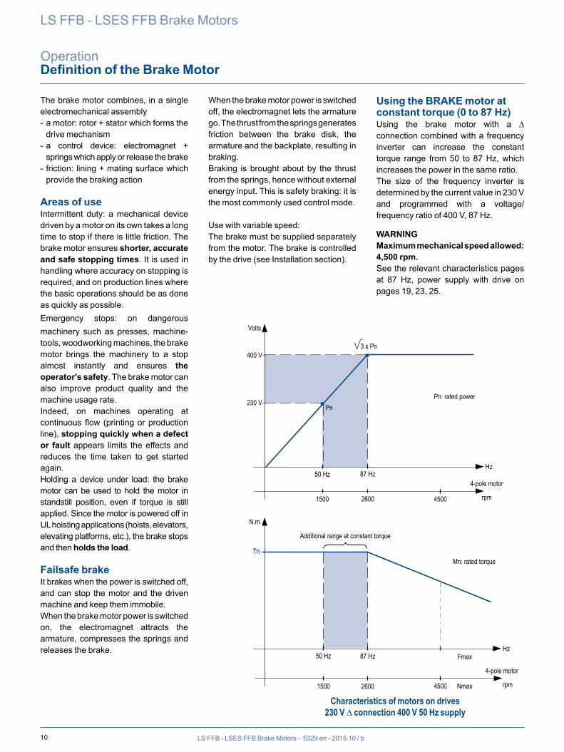
Using the BRAKE motor at constant torque (0 to 87 Hz)Using the brake motor with a ∆ connection combined with a frequency inverter can increase the constant torque range from 50 to 87 Hz, which increases the power in the same ratio.The size of the frequency inverter is determined by the current value in 230 V and programmed with a voltage/frequency ratio of 400 V, 87 Hz.
WARNINGMaximum mechanical speed allowed: 4,500 rpm.See the relevant characteristics pages at 87 Hz, power supply with drive on pages 19, 23, 25.
LS FFB - LSES FFB Brake Motors
OperationDefinition of the Brake Motor
Volts
400 V
Pn
50 Hz 87 HzHz
230 V
1500 2600
Pn: rated power
3 x Pn
4-pole motor
rpm
N.m
Tn
Additional range at constant torque
50 Hz 87 Hz Fmax
Nmax4500
Hz
4-pole motor
rpm1500 2600
4500
Mn: rated torque
Characteristics of motors on drives 230 V ∆ connection 400 V 50 Hz supply
11LS FFB - LSES FFB Brake Motors - 5329 en - 2015.10 / b
LS FFB - LSES FFB Brake Motors
OperationDuty Cycle Definitions
CONDITIONS AND DUTY CYCLESCONDITIONSBy “condition”, we mean all the electrical and mechanical values that typify machine operation at a given time.
DUTY CYCLES (according to IEC 60034-1)By “duty”, we mean the stipulated conditions to which the machine is subjected, their respective durations and order of succession over time.
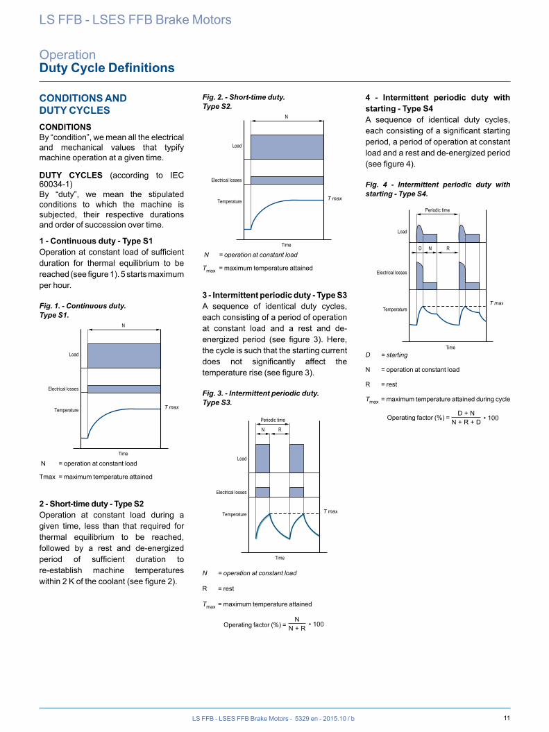
1 - Continuous duty - Type S1Operation at constant load of sufficient duration for thermal equilibrium to be reached (see figure 1). 5 starts maximum per hour.
Fig. 1. - Continuous duty.Type S1.
Load
Electrical losses
Temperature
Time
N
T max
N = operation at constant load
Tmax = maximum temperature attained
2 - Short-time duty - Type S2Operation at constant load during a given time, less than that required for thermal equilibrium to be reached, followed by a rest and de-energized period of sufficient duration to re-establish machine temperatures within 2 K of the coolant (see figure 2).
Fig. 2. - Short-time duty.Type S2.
Load
Electrical losses
Temperature
Time
N
T max
Load
Electrical losses
Temperature
Time
N
T max
N = operation at constant load
Tmax = maximum temperature attained
3 - Intermittent periodic duty - Type S3A sequence of identical duty cycles, each consisting of a period of operation at constant load and a rest and de-energized period (see figure 3). Here, the cycle is such that the starting current does not significantly affect the temperature rise (see figure 3).
Fig. 3. - Intermittent periodic duty.Type S3.
Load
Electrical losses
Temperature
Time
N
T max
R
Periodic time
N = operation at constant load
R = rest
Tmax = maximum temperature attained
Operating factor (%) = N
• 100N + R
N• 100N + V
D + N1 100 %D + N1 + F1 + N2 + F2 + N3
F1 + N2 100 %D + N1 + F1 + N2 + F2 + N3
F2 + N3 100 %D + N1 + F1 + N2 + F2 + N3
LN
D + N• 100N + R + D
D + N + F• 100D + N + F + R
4 - Intermittent periodic duty with starting - Type S4A sequence of identical duty cycles, each consisting of a significant starting period, a period of operation at constant load and a rest and de-energized period (see figure 4).
Fig. 4 - Intermittent periodic duty with starting - Type S4.
Load
Electrical losses
Temperature
Time
N
T max
R
Periodic time
D
D = starting
N = operation at constant load
R = rest
Tmax = maximum temperature attained during cycle
Operating factor (%) = N
• 100N + R
N• 100N + V
D + N1 100 %D + N1 + F1 + N2 + F2 + N3
F1 + N2 100 %D + N1 + F1 + N2 + F2 + N3
F2 + N3 100 %D + N1 + F1 + N2 + F2 + N3
LN
D + N• 100N + R + D
D + N + F• 100D + N + F + R
Duty cycles
12 LS FFB - LSES FFB Brake Motors - 5329 en - 2015.10 / b
LS FFB - LSES FFB Brake Motors
OperationDuty Cycle Definitions
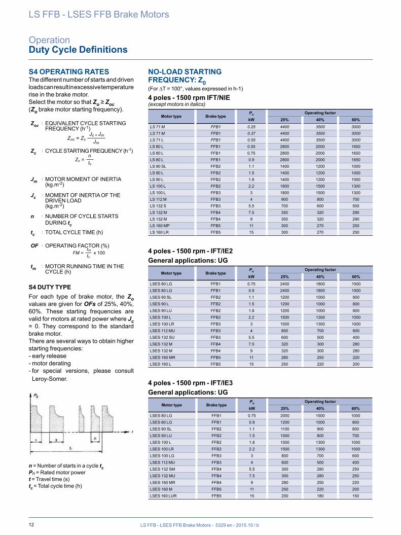
S4 OPERATING RATESThe different number of starts and driven loads can result in excessive temperature rise in the brake motor.Select the motor so that Zo ≥ Zoc (Zo brake motor starting frequency).
Zoc : EQUIVALENT CYCLE STARTING FREQUENCY (h-1)
Zoc = Zc Jc + Jm
Jm
Zc = ntc
FM = x 100tmtc
Zc : CYCLE STARTING FREQUENCY (h-1)
Zoc = Zc Jc + Jm
Jm
Zc = ntc
FM = x 100tmtcJm : MOTOR MOMENT OF INERTIA
(kg.m-2)
Jc : MOMENT OF INERTIA OF THE DRIVEN LOAD(kg.m-2)
n : NUMBER OF CYCLE STARTS DURING tc
tc : TOTAL CYCLE TIME (h)
OF : OPERATING FACTOR (%)
Zoc = Zc Jc + Jm
Jm
Zc = ntc
FM = x 100tmtc
tm : MOTOR RUNNING TIME IN THE CYCLE (h)
S4 DUTY TYPEFor each type of brake motor, the Zo values are given for OFs of 25%, 40%, 60%. These starting frequencies are valid for motors at rated power where Jc = 0. They correspond to the standard brake motor.There are several ways to obtain higher starting frequencies:- early release- motor derating- for special versions, please consult Leroy-Somer.
n = Number of starts in a cycle tcPn = Rated motor powert = Travel time (s)tc = Total cycle time (h)
NO-LOAD STARTING FREQUENCY: Z0(For ∆T = 100°, values expressed in h-1)
4 poles - 1500 rpm IFT/NIE(except motors in italics)
Motor type Brake typePn Operating factorkW 25% 40% 60%
LS 71 M FFB1 0.25 4400 3500 3000LS 71 M FFB1 0.37 4400 3500 3000LS 71 L FFB1 0.55 4400 3500 3000LS 80 L FFB1 0.55 2800 2000 1650LS 80 L FFB1 0.75 2800 2000 1650LS 80 L FFB1 0.9 2800 2000 1650LS 90 SL FFB2 1.1 1400 1200 1000LS 90 L FFB2 1.5 1400 1200 1000LS 90 L FFB2 1.8 1400 1200 1000LS 100 L FFB2 2.2 1800 1500 1300LS 100 L FFB3 3 1800 1500 1300LS 112 M FFB3 4 900 800 700LS 132 S FFB3 5.5 700 600 500LS 132 M FFB4 7.5 350 320 290LS 132 M FFB4 9 350 320 290LS 160 MP FFB5 11 300 270 250LS 160 LR FFB5 15 300 270 250
4 poles - 1500 rpm - IFT/IE2General applications: UG
Motor type Brake typePn Operating factorkW 25% 40% 60%
LSES 80 LG FFB1 0.75 2400 1800 1500LSES 80 LG FFB1 0.9 2400 1800 1500LSES 90 SL FFB2 1.1 1200 1000 800LSES 90 L FFB2 1.5 1200 1000 800LSES 90 LU FFB2 1.8 1200 1000 800LSES 100 L FFB2 2.2 1500 1300 1000LSES 100 LR FFB3 3 1500 1300 1000LSES 112 MU FFB3 4 800 700 600LSES 132 SU FFB3 5.5 600 500 400LSES 132 M FFB4 7.5 320 300 280LSES 132 M FFB4 9 320 300 280LSES 160 MR FFB5 11 280 250 220LSES 160 L FFB5 15 250 220 200
4 poles - 1500 rpm - IFT/IE3General applications: UG
Motor type Brake typePn Operating factorkW 25% 40% 60%
LSES 80 LG FFB1 0.75 2000 1500 1000LSES 80 LG FFB1 0.9 1200 1000 800LSES 90 SL FFB2 1.1 1100 900 800LSES 90 LU FFB2 1.5 1000 800 700LSES 100 L FFB2 1.8 1500 1300 1000LSES 100 LR FFB2 2.2 1500 1300 1000LSES 100 LG FFB3 3 800 700 600LSES 112 MU FFB3 4 600 500 400LSES 132 SM FFB4 5.5 300 280 250LSES 132 MU FFB4 7.5 300 280 250LSES 160 MR FFB4 9 280 250 220LSES 160 M FFB5 11 250 220 200LSES 160 LUR FFB5 15 200 180 150
13LS FFB - LSES FFB Brake Motors - 5329 en - 2015.10 / b
LS FFB - LSES FFB Brake Motors
OperationElectromagnet Characteristics
The DC electromagnet consists of a resin-coated coil in a cast iron yoke.The yoke and the armature form the magnetic circuit.All our coils are made for a DC voltage of 180 VDC (400 or 230 VAC supply) or
20 VDC (24 VAC supply). All the electromagnets are class F and can be continuously supplied with power.Since it is difficult to distinguish between some DC coils by size alone, the coil resistance should be measured with an
appropriately rated ohmmeter and compared with the value given in the table below.These values are theoretical, calculated for an ambient temperature of 20°C.
Electromagnet characteristics ±5%, at 20°CType 180 V coil 20 V coil
brake CurrentA
ResistanceΩ
PowerW
CurrentA
ResistanceΩ
PowerW
FFB1 0.232 776 42 1.974 10.1 39FFB2 0.295 610 53 2.633 7.6 53FFB3 0.345 522 62 2.793 7.2 56FFB4 0.339 530 61 3.602 5.6 72FFB5 0.547 329 98 4.211 4.8 84
Brake Power Supply Unit Characteristics
OPERATING PRINCIPLE
Brake coilDC output voltage
AC input voltage Power supply unit
DEFINITION OF BUILT-IN OR SEPARATE POWER SUPPLY Built-in power supply:The rectifier power supply unit is connected in parallel on the motor power supply.S08 cubicle, 180 VDC coil for standard single-speed brake motor.
DEB
RA
NC
HER
LE BLO
C R
EDR
ESSEUR
POU
R ESSA
I D'ISO
LEMEN
T OU
DIELEC
TRIQ
UE
DISC
ON
NEC
T THE R
ECTIFIER
CELL W
HEN
TESTING
FOR
CU
RR
ENT IN
SULATIO
N O
R D
IELECTR
IC.
634118 fr-en/f
IMPO
RTA
NT
1 vitesse - 2 tensions (rapport 1.732) 1 bobinage1 speed- 2 voltage (ratio 1.732) 1 w
inding
W2 T6
U1 T1
U2 T4
V1 T2
V2 T5
W1 T3
W2 T6
U1 T1
U2 T4
V1 T2
V2 T5
W1 T3
**S08
**S08
**débrancher les shunts dans le cas d'une alimentation séparée**disconnect the shunts for separate power supply
(A) coupure sur continu : temps de réponse réduitobligatoire en levage : ENLEVER LE STRAP
(A) DC braking : shorter response timeMandatory for lifting application : REMOVE WIRE
Schéma de branchem
ent frein / Brake connection diagram
AlimentationPower supply
BobineCoil
400V AC230V AC
230V AC127V AC
180V DC100V DC
180V DC100V DC
Câblage*Cabling*
2
1
Bobine/coilAlimentationPower supply
S O8~
~
~ _ -+ ++
(A)±15%
2
1
*suivant alimentation et bobine* according power supply and coil*suivant alimentation et bobine* according power supply and coil
Separate power supply:The motor and rectifier unit power supplies are independent. In this instance the AC input voltage to be used to supply the rectifier unit should be stated.S06 cubicle, 20 VDC coil, 24 V separate power supply
IMPORTANTDébrancher le bloc redresseur
pour essai d’isolement ou diélectriqueDisconnect the rectifier cell when testing
for current insulation or dielectric
Schéma de branchementConnection diagram
FREIN - BRAKECoupure sur le continu(obligatoire en levage)ENLEVER LE STRAPConnection for shorter
response time(mandatory for hoisting)REMOVE THE STRAP
24V
20V
E FS O6
~
~
~ -+
ELECTRO-MAGNET CHARACTERISTICS
14 LS FFB - LSES FFB Brake Motors - 5329 en - 2015.10 / b
LS FFB - LSES FFB Brake Motors
OperationBraking Torques
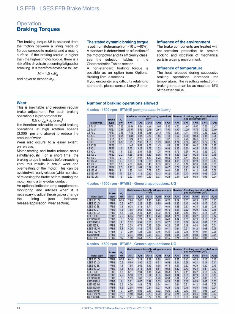
The braking torque Mf is obtained from the friction between a lining made of fibrous composite material and a mating surface. If the braking torque is higher than the highest motor torque, there is a risk of the drivetrain becoming fatigued or breaking. It is therefore advisable to use:
Mf = 1.5 x Mnand never to exceed MD.
The stated dynamic braking torque is optimum (tolerance from -10 to +40%).A standard is determined as a function of the motor power and its efficiency class: see the selection tables in the Characteristics Tables section.A non-standard braking torque is possible as an option (see Optional Braking Torque section).If you encounter any difficulty relating to standards, please consult Leroy-Somer.
Influence of the environmentThe brake components are treated with anti-corrosion protection to prevent sticking and oxidation of mechanical parts in a damp environment.
Influence of temperatureThe heat released during successive braking operations increases the temperature. The resulting reduction in braking torque can be as much as 15% of the rated value.
WearThis is inevitable and requires regular brake adjustment. For each braking operation it is proportional to:
0.5 x (Jm + Jc) x ωN2
It is therefore advisable to avoid braking operations at high rotation speeds (3,000 pm and above) to reduce the amount of wear.Wear also occurs, to a lesser extent, on release.Motor starting and brake release occur simultaneously. For a short time, the braking torque is reduced before reaching zero; this results in brake wear and overheating of the motor. This can be avoided with early release (which consists of releasing the brake before starting the motor, using a time-delay contact.An optional indicator lamp supplements monitoring and advises when it is necessary to adjust the air gap or change the lining (see Indicator: release/application, wear section).
Number of braking operations allowed4 poles - 1500 rpm - IFT/NIE (except motors in italics)
Motor typeBrake type
PnkW
Maximum number of braking operations (106)
Number of braking operations before air gap adjustment (106)
FJ=1 FJ=5 FJ=10 FJ=15 FJ=20 FJ=1 FJ=5 FJ=10 FJ=15 FJ=20LS 71 M FFB1 0.25 24.64 8.21 4.48 3.08 2.35 4.93 1.64 0.90 0.62 0.47LS 71 M FFB1 0.37 20.87 6.96 3.79 2.61 1.99 4.17 1.39 0.76 0.52 0.40LS 71 L FFB1 0.55 17.03 5.68 3.10 2.13 1.62 3.41 1.14 0.62 0.43 0.32LS 80 L FFB1 0.55 14.84 4.95 2.70 1.85 1.41 2.97 0.99 0.54 0.37 0.28LS 80 L FFB1 0.75 11.24 3.75 2.04 1.41 1.07 2.25 0.75 0.41 0.28 0.21LS 80 L FFB1 0.9 8.71 2.90 1.58 1.09 0.83 1.74 0.58 0.32 0.22 0.17LS 90 SL FFB2 1.1 11.46 3.82 2.08 1.43 1.09 2.29 0.76 0.42 0.29 0.22LS 90 L FFB2 1.5 9.75 3.25 1.77 1.22 0.93 1.95 0.65 0.35 0.24 0.19LS 90 L FFB2 1.8 8.67 2.89 1.58 1.08 0.83 1.73 0.58 0.32 0.22 0.17LS 100 L FFB2 2.2 7.66 2.55 1.39 0.96 0.73 1.53 0.51 0.28 0.19 0.15LS 100 L FFB3 3 6.21 2.07 1.13 0.78 0.59 1.24 0.41 0.23 0.16 0.12LS 112 M FFB3 4 5.23 1.74 0.95 0.65 0.50 1.05 0.35 0.19 0.13 0.10LS 132 S FFB3 5.5 2.66 0.89 0.48 0.33 0.25 0.53 0.18 0.10 0.07 0.05LS 132 M FFB4 7.5 4.91 1.64 0.89 0.61 0.47 0.74 0.25 0.13 0.09 0.07LS 132 M FFB4 9 4.23 1.41 0.77 0.53 0.40 0.63 0.21 0.12 0.08 0.06LS 160 MP FFB5 11 3.41 1.14 0.62 0.43 0.32 0.51 0.17 0.09 0.06 0.05LS 160 LR FFB5 15 2.92 0.97 0.53 0.37 0.28 0.44 0.15 0.08 0.05 0.04
4 poles - 1500 rpm - IFT/IE2 - General applications: UG
Motor typeBrake type
PnkW
Maximum number of braking operations (106)
Number of braking operations before air gap adjustment (106)
FJ=1 FJ=5 FJ=10 FJ=15 FJ=20 FJ=1 FJ=5 FJ=10 FJ=15 FJ=20LSES 80 LG FFB1 0.75 7.96 2.65 1.45 0.99 0.76 1.59 0.53 0.29 0.20 0.15LSES 80 LG FFB1 0.9 6.77 2.26 1.23 0.85 0.65 1.35 0.45 0.25 0.17 0.13LSES 90 SL FFB2 1.1 9.38 3.13 1.71 1.17 0.89 1.88 0.63 0.34 0.23 0.18LSES 90 L FFB2 1.5 7.85 2.62 1.43 0.98 0.75 1.57 0.52 0.29 0.20 0.15LSES 90 LU FFB2 1.8 7.38 2.46 1.34 0.92 0.70 1.48 0.49 0.27 0.18 0.14LSES 100 L FFB2 2.2 6.05 2.02 1.10 0.76 0.58 1.21 0.40 0.22 0.15 0.12LSES 100 LR FFB3 3 5.18 1.73 0.94 0.65 0.49 1.04 0.35 0.19 0.13 0.10LSES 112 MU FFB3 4 2.82 0.94 0.51 0.35 0.27 0.56 0.19 0.10 0.07 0.05LSES 132 SU FFB3 5.5 2.33 0.78 0.42 0.29 0.22 0.47 0.16 0.08 0.06 0.04LSES 132 M FFB4 7.5 4.25 1.42 0.77 0.53 0.41 0.64 0.21 0.12 0.08 0.06LSES 132 M FFB4 9 3.69 1.23 0.67 0.46 0.35 0.55 0.18 0.10 0.07 0.05LSES 160 MR FFB5 11 2.94 0.98 0.53 0.37 0.28 0.44 0.15 0.08 0.06 0.04LSES 160 L FFB5 15 1.59 0.53 0.29 0.20 0.15 0.24 0.08 0.04 0.03 0.02
4 poles - 1500 rpm - IFT/IE3 - General applications: UG
Motor typeBrake type
PnkW
Maximum number of braking operations (106)
Number of braking operations before air gap adjustment (106)
FJ=1 FJ=5 FJ=10 FJ=15 FJ=20 FJ=1 FJ=5 FJ=10 FJ=15 FJ=20LSES 80 LG FFB1 0.75 6.42 2.14 1.17 0.80 0.61 1.28 0.43 0.23 0.16 0.12LSES 80 LG FFB1 0.9 5.69 1.90 1.03 0.71 0.54 1.14 0.38 0.21 0.14 0.11LSES 90 SL FFB2 1.1 7.85 2.62 1.43 0.98 0.75 1.57 0.52 0.29 0.20 0.15LSES 90 LU FFB2 1.5 6.48 2.16 1.18 0.81 0.62 1.30 0.43 0.24 0.6 0.12LSES 100 L FFB2 1.8 6.11 2.04 1.11 0.76 0.58 1.22 0.41 0.22 0.15 0.12LSES 100 LR FFB2 2.2 5.18 1.73 0.94 0.65 0.49 1.04 0.35 0.19 0.13 0.10LSES 100 LG FFB3 3 3.19 1.06 0.58 0.40 0.30 0.64 0.21 0.12 0.08 0.06LSES 112 MU FFB3 4 2.61 0.87 0.47 0.33 0.25 0.52 0.17 0.09 0.07 0.05LSES 132 SM FFB4 5.5 4.30 1.43 0.78 0.54 0.41 0.64 0.21 0.12 0.08 0.06LSES 132 MU FFB4 7.5 2.98 0.99 0.54 0.37 0.28 0.45 0.15 0.08 0.06 0.04LSES 160 MR FFB4 9 2.59 0.86 0.47 0.32 0.25 0.39 0.13 0.07 0.05 0.04LSES 160 M FFB5 11 1.59 0.53 0.29 0.20 0.15 0.24 0.08 0.04 0.03 0.02LSES 160 LUR FFB5 15 1.21 0.40 0.22 0.15 0.11 0.18 0.06 0.03 0.02 0.02
MOMENT OF INERTIA
15LS FFB - LSES FFB Brake Motors - 5329 en - 2015.10 / b
LS FFB - LSES FFB Brake Motors
OperationBraking Torques
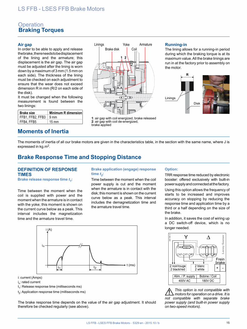
DEFINITION OF RESPONSE TIMES Brake release response time t1:
Time between the moment when the coil is supplied with power and the moment when the armature is in contact with the yoke; this moment is shown on the current curve below as a peak. This interval includes the magnetization time and the armature travel time.
Brake application (engage) response time t2: Time between the moment when the coil power supply is cut and the moment when the armature is in contact with the disk; this moment is shown on the current curve below as a peak. This interval includes the demagnetization time and the armature travel time.
Option: TRR response time reduced by electronic booster: offered exclusively with built-in power supply and connected at the factory.Using this option allows the frequency of starts to be increased and improves accuracy on stopping by reducing the response time and application time by a third or a half depending on the size of the brake.In addition, it saves the cost of wiring up a DC switch-off device, which is no longer needed.
Freinbrake
2 noir/rouge2 black/red
Alim. / P. supply400V AC
Bobine / Coil180V DC
+ -2 blanc2 white
634
108
/ b
W2 U2 V2
U1 V1 W1
W2 U2 V2
V1 W1U1
This option is not compatible with motors for operation on a drive. It is
not compatible with separate brake power supply (and built-in power supply on two-speed motors).
t (ms)
i (A)
in
t2 t1
i: current (Amps)in: rated currentt1: Release response time (milliseconds ms)t2: Application response time (milliseconds ms)
The brake response time depends on the value of the air gap adjustment. It should therefore be checked regularly (see above).
Brake Response Time and Stopping Distance
Moments of InertiaThe moments of inertia of all our brake motors are given in the characteristics table, in the section with the same name, where J is expressed in kg.m2.
Air gapIn order to be able to apply and release the brake, there needs to be displacement of the lining and the armature; this displacement is the air gap. The air gap must be adjusted after the lining is worn down by a maximum of 3 mm (1.5 mm on each side). The thickness of the lining must be checked on each adjustment to ensure that the wear does not exceed dimension R in mm (R/2 on each side of the disk).It must be changed when the following measurement is found between the two linings:
Brake size Minimum R dimensionFFB1, FFB2, FFB3 9 mmFFB4, FFB5 15 mm
1: air gap with coil energized, brake released2: air gap with coil de-energized, brake applied
Running-inThe lining allows for a running-in period during which the braking torque is at its maximum value. All the brake linings are run in at the factory prior to assembly on the motor.
R
LiningsDisk
LiningsBrake disk
YokeCoil
Armature
1 2
RESPONSE TIME WITH BRAKE ONLY AND STOPPING DISTANCE
16 LS FFB - LSES FFB Brake Motors - 5329 en - 2015.10 / b
LS FFB - LSES FFB Brake Motors
OperationBrake Response Time and Stopping Distance
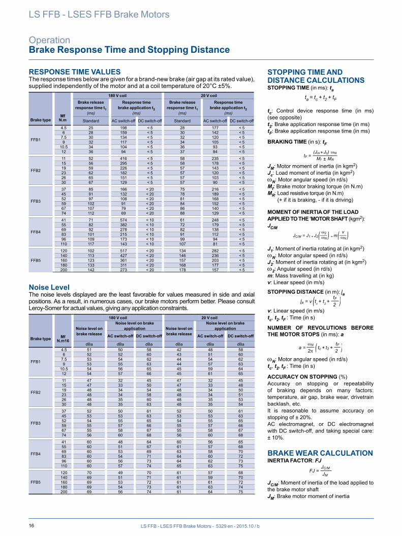
RESPONSE TIME VALUES The response times below are given for a brand-new brake (air gap at its rated value), supplied independently of the motor and at a coil temperature of 20°C ±5%.
Brake typeMf
N.m
180 V coil 20 V coilBrake release
response time t1 (ms)
Response timebrake application t2
(ms)
Brake release response time t1
(ms)
Response timebrake application t2
(ms)
Standard AC switch-off DC switch-off Standard AC switch-off DC switch-off
FFB1
4.5 25 198 < 5 28 177 < 56 28 159 < 5 30 142 < 5
7.5 30 134 < 5 32 120 < 59 32 117 < 5 34 105 < 5
10.5 34 104 < 5 36 93 < 512 36 94 < 5 37 84 < 5
FFB2
11 52 416 < 5 58 235 < 515 56 295 < 5 58 178 < 519 59 226 < 5 57 143 < 523 62 182 < 5 57 120 < 526 65 151 < 5 57 103 < 530 67 129 < 5 57 90 < 5
FFB3
37 85 166 < 20 75 216 < 545 91 132 < 20 78 189 < 552 97 108 < 20 81 168 < 559 102 91 < 20 84 152 < 567 107 79 < 20 86 140 < 574 112 69 < 20 88 129 < 5
FFB4
41 71 574 < 10 61 248 < 555 82 382 < 10 72 179 < 569 92 278 < 10 82 138 < 583 101 215 < 10 91 112 < 596 109 173 < 10 99 94 < 5110 117 143 < 10 107 81 < 5
FFB5
120 102 517 < 20 134 282 < 5140 113 427 < 20 146 236 < 5160 123 361 < 20 157 203 < 5180 133 311 < 20 168 177 < 5200 142 273 < 20 178 157 < 5
Noise Level The noise levels displayed are the least favorable for values measured in side and axial positions. As a result, in numerous cases, our brake motors perform better. Please consult Leroy-Somer for actual values, giving any application constraints.
180 V coil 20 V coil
Noise level on brake release
Noise level on brake application Noise level on
brake release
Noise level on brake application
Brake type MfN.m16
AC switch-off DC switch-off AC switch-off DC switch-off
dBa dBa dBa dBa dBa dBa
FFB1
4.5 51 50 58 42 48 586 52 52 60 43 51 60
7.5 53 54 62 44 54 629 53 55 63 44 57 63
10.5 54 56 65 45 59 6412 54 57 66 45 61 65
FFB2
11 47 32 45 47 32 4515 47 33 50 47 33 4819 48 34 54 48 34 5023 48 34 58 48 34 5126 48 35 60 48 35 5330 48 35 63 48 35 54
FFB3
37 52 50 61 52 50 6145 53 53 63 53 53 6352 54 55 65 54 55 6559 55 57 66 55 57 6667 55 58 67 55 58 6774 56 60 68 56 60 68
FFB4
41 60 48 64 60 56 6555 60 51 67 61 57 6869 60 53 69 63 58 7083 60 54 71 64 60 7296 60 56 73 64 62 73110 60 57 74 65 63 75
FFB5
120 70 49 70 61 57 68140 69 51 71 61 59 70160 69 53 72 61 61 72180 69 54 73 61 63 74200 69 56 74 61 64 75
STOPPING TIME AND DISTANCE CALCULATIONSSTOPPING TIME (in ms): ta
ta = tc + t2 + tF
tc: Control device response time (in ms) (see opposite)t2: Brake application response time (in ms)tF: Brake application response time (in ms)
BRAKING TIME (in s): tF
tF = (Jm Jc) ωN
Mf MR
+±
JM: Motor moment of inertia (in kgm2)Jc: Load moment of inertia (in kgm2)wN: Motor angular speed (in rd/s)Mf: Brake motor braking torque (in N.m)MR: Load resistive torque (in N.m)
(+ if it is braking, - if it is driving)
MOMENT OF INERTIA OF THE LOAD APPLIED TO THE ’MOTOR SHAFT (kgm2): JC/M
JC/M = J1 + J2 + m
ω2ωN
vωN
J1: Moment of inertia rotating at (in kgm2)wN: Motor angular speed (in rd/s)J2: Moment of inertia rotating at (in kgm2)w2: Angular speed (in rd/s)m: Mass travelling at (in kg)v: Linear speed (in m/s)
STOPPING DISTANCE (in m): ɭaɭa =
v tc + t2 +
tF2
v: Linear speed (in m/s)tc, t2, tF : Time (in s)
NUMBER OF REVOLUTIONS BEFORE THE MOTOR STOPS (in ms): a
a =
tc + t2 +ωN
2πtF
2
wN: Motor angular speed (in rd/s)tc, t2, tF : Time (in s)
ACCURACY ON STOPPING (%)Accuracy on stopping or repeatability of braking depends on many factors: temperature, air gap, brake wear, drivetrain backlash, etc.It is reasonable to assume accuracy on stopping of ± 20%.AC electromagnet, or DC electromagnet with DC switch-off, and taking special care: ± 10%.
BRAKE WEAR CALCULATIONINERTIA FACTOR: FJ
FJ =JC/M
JM
JC/M: Moment of inertia of the load applied to the brake motor shaftJM: Brake motor moment of inertia
17LS FFB - LSES FFB Brake Motors - 5329 en - 2015.10 / b
LS FFB - LSES FFB Brake Motors
OperationBrake Response Time and Stopping Distance
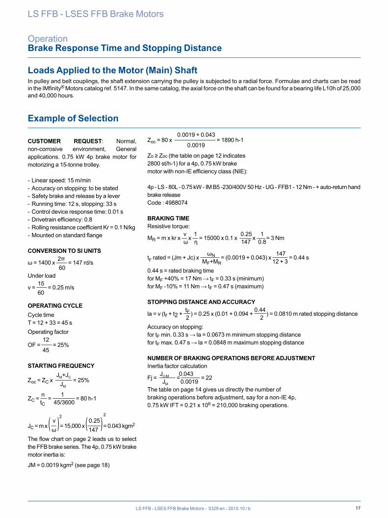
Loads Applied to the Motor (Main) ShaftIn pulley and belt couplings, the shaft extension carrying the pulley is subjected to a radial force. Formulae and charts can be read in the IMfinity® Motors catalog ref. 5147. In the same catalog, the axial force on the shaft can be found for a bearing life L10h of 25,000 and 40,000 hours.
CUSTOMER REQUEST: Normal, non-corrosive environment, General applications. 0.75 kW 4p brake motor for motorizing a 15-tonne trolley.
- Linear speed: 15 m/min- Accuracy on stopping: to be stated- Safety brake and release by a lever- Running time: 12 s, stopping: 33 s- Control device response time: 0.01 s- Drivetrain efficiency: 0.8- Rolling resistance coefficient Kr = 0.1 N/kg- Mounted on standard flange
CONVERSION TO SI UNITS 2πω = 1400 x = 147 rd/s 60Under load 15v = = 0.25 m/s 60
OPERATING CYCLECycle timeT = 12 + 33 = 45 sOperating factor 12OF = = 25% 45
STARTING FREQUENCY JM+JCZoc = ZC x = 25% JM
n 1ZC = = = 80 h-1 tC 45/3600
v 2 0.25 2 JC = m x ( ) = 15,000 x ( ) = 0.043 kgm2 ω 147The flow chart on page 2 leads us to select the FFB brake series. The 4p, 0.75 kW brake motor inertia is:
JM = 0.0019 kgm2 (see page 18)
Example of Selection
4p - LS - 80L - 0.75 kW - IM B5 -230/400V 50 Hz - UG - FFB1 - 12 Nm - + auto-return hand brake releaseCode : 4988074
BRAKING TIMEResistive torque: v 1 0.25 1MR = m x kr x x = 15000 x 0.1 x x = 3 Nm ω ƞ 147 0.8
ωN 147tF rated = (Jm + Jc) x = (0.0019 + 0.043) x = 0.44 s MF+MR 12 + 30.44 s = rated braking timefor MF +40% = 17 Nm → tF = 0.33 s (minimum)for MF -10% = 11 Nm → tF = 0.47 s (maximum)
STOPPING DISTANCE AND ACCURACY tF 0.44la = v (tr + t2 + ) = 0.25 x (0.01 + 0.094 + ) = 0.0810 m rated stopping distance 2 2Accuracy on stopping:for tF min. 0.33 s → la = 0.0673 m minimum stopping distancefor tF max. 0.47 s → la = 0.0848 m maximum stopping distance
NUMBER OF BRAKING OPERATIONS BEFORE ADJUSTMENTInertia factor calculation JC/M 0.043Fj = = = 22 JM 0.0019The table on page 14 gives us directly the number of braking operations before adjustment, say for a non-IE 4p, 0.75 kW IFT = 0.21 x 106 = 210,000 braking operations.
0.0019 + 0.043Zoc = 80 x = 1890 h-1 0.0019
Zo ≥ Zoc (the table on page 12 indicates 2800 st/h-1) for a 4p, 0.75 kW brake motor with non-IE efficiency class (NIE):
18 LS FFB - LSES FFB Brake Motors - 5329 en - 2015.10 / b
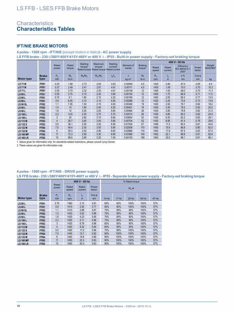
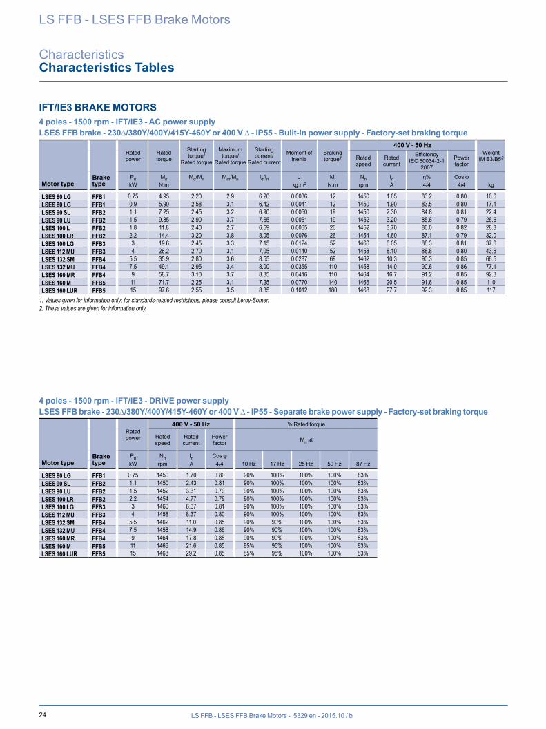
IFT/NIE BRAKE MOTORS 4 poles - 1500 rpm - IFT/NIE (except motors in italics) - AC power supplyLS FFB brake - 230∆/380Y/400Y/415Y-460Y or 400 V ∆ - IP55 - Built-in power supply - Factory-set braking torque
Motor typeBrake type
Rated power
Rated torque
Starting torque/
Rated torque
Maximum torque/
Rated torque
Starting current/
Rated current
Moment of inertia
Braking torque1
400 V - 50 HzWeight
IM B3/B52Rated speed
Rated current
EfficiencyIEC 60034-2-1
2007
Power factor
Pn Mn Md/Mn Mm/Mn Id/In J Mf Nn In η % Cos φkW N.m kg.m2 N.m rpm A 4/4 4/4 kg
4 poles - 1500 rpm - IFT/NIE - DRIVE power supplyLS FFB brake - 230∆/380Y/400Y/415Y-460Y or 400 V ∆ - IP55 - Separate brake power supply - Factory-set braking torque
Motor typeBrake type
Rated power
400 V - 50 Hz % Rated torque
Rated speed
Rated current
Power factor Mn at
Pn Nn In Cos φkW rpm A 4/4 10 Hz 17 Hz 25 Hz 50 Hz 87 Hz
LS FFB - LSES FFB Brake Motors
CharacteristicsCharacteristics Tables
LS 71 M FFB1 0.25 1.68 2.73 2.93 4.63 0.00094 4.5 1425 0.80 67.0 0.65 9.4LS 71 M FFB1 0.37 2.49 2.41 2.81 4.91 0.00111 4.5 1420 1.06 70.0 0.70 10.3LS 71 L FFB1 0.55 3.75 2.32 2.53 4.81 0.00136 12 1400 1.62 68.0 0.70 11.3LS 80 L FFB1 0.55 3.75 2.15 2.30 3.90 0.00154 12 1405 1.70 66.9 0.71 11.5LS 80 L FFB1 0.75 5.1 1.80 2.15 4.25 0.00190 12 1400 2.05 69.3 0.77 13.5LS 80 L FFB1 0.9 6.05 3.10 3.10 5.55 0.00266 12 1425 2.45 73.0 0.73 13.9LS 90 SL FFB2 1.1 7.35 1.50 2.15 4.50 0.00349 19 1425 2.50 76.1 0.84 18.2LS 90 L FFB2 1.5 10 1.90 2.40 5.25 0.00421 19 1430 3.30 79.2 0.83 20.0LS 90 L FFB2 1.8 12 2.00 2.55 5.60 0.00464 26 1435 3.95 79.9 0.82 21.0LS 100 L FFB2 2.2 14.6 2.30 2.70 5.70 0.00514 26 1435 4.80 80.2 0.82 24.9LS 100 L FFB3 3 20 2.60 3.10 6.65 0.00654 52 1435 6.35 82.2 0.83 29.1LS 112 M FFB3 4 26.7 2.65 3.05 5.85 0.00704 52 1430 8.95 81.4 0.79 29.6LS 132 S FFB3 5.5 36.1 2.55 3.20 6.95 0.01534 67 1456 11.5 85.4 0.81 44.6LS 132 M FFB4 7.5 49.4 2.30 3.00 5.90 0.02508 110 1450 15.6 86.8 0.80 62.5LS 132 M FFB4 9 59.3 2.40 2.95 6.60 0.02868 110 1450 17.8 87.5 0.83 67.4LS 160 MP FFB5 11 72.3 2.90 3.30 6.85 0.03366 140 1452 22.1 88.8 0.81 82.9LS 160 LR FFB5 15 98.5 2.85 3.35 7.45 0.04153 180 1454 30.0 89.1 0.81 96.1
1. Values given for information only; for standards-related restrictions, please consult Leroy-Somer.2. These values are given for information only.
LS 80 L FFB1 0.75 1380 2.10 0.81 65% 80% 100% 100% 57%LS 80 L FFB1 0.9 1415 2.50 0.77 65% 80% 100% 100% 57%LS 90 SL FFB2 1.1 1410 2.68 0.87 75% 85% 90% 100% 57%LS 90 L FFB2 1.5 1420 3.52 0.86 75% 85% 90% 100% 57%LS 90 L FFB2 1.8 1425 4.23 0.85 75% 85% 90% 100% 57%LS 100 L FFB2 2.2 1425 5.11 0.86 75% 85% 90% 100% 57%LS 100 L FFB3 3 1425 6.78 0.86 60% 85% 90% 100% 57%LS 112 M FFB3 4 1420 9.32 0.84 60% 85% 90% 100% 57%LS 132 S FFB3 5.5 1450 11.9 0.86 70% 85% 100% 100% 57%LS 132 M FFB4 7.5 1445 15.7 0.82 90% 100% 100% 100% 57%LS 132 M FFB4 9 1440 18.8 0.86 90% 100% 100% 100% 57%LS 160 MP FFB5 11 1450 22.3 0.83 90% 100% 100% 100% 57%LS 160 LR FFB5 15 1450 30.3 0.83 90% 100% 100% 100% 57%
19LS FFB - LSES FFB Brake Motors - 5329 en - 2015.10 / b
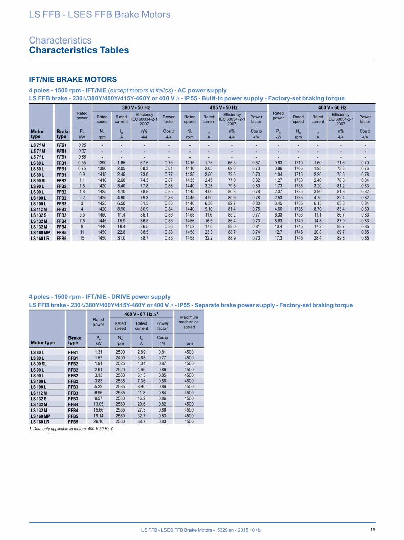
IFT/NIE BRAKE MOTORS 4 poles - 1500 rpm - IFT/NIE (except motors in italics) - AC power supplyLS FFB brake - 230∆/380Y/400Y/415Y-460Y or 400 V ∆ - IP55 - Built-in power supply - Factory-set braking torque
Motor type
Brake type
Rated power
380 V - 50 Hz 415 V - 50 HzRated power
460 V - 60 Hz
Rated speed
Rated current
EfficiencyIEC 60034-2-1
2007
Power factor
Rated speed
Rated current
EfficiencyIEC 60034-2-1
2007
Power factor
Rated speed
Rated current
EfficiencyIEC 60034-2-1
2007
Power factor
Pn Nn In η% Cos φ Nn In η% Cos φ Pn Nn In η% Cos φkW rpm A 4/4 4/4 rpm A 4/4 4/4 kW rpm A 4/4 4/4
4 poles - 1500 rpm - IFT/NIE - DRIVE power supplyLS FFB brake - 230∆/380Y/400Y/415Y-460Y or 400 V ∆ - IP55 - Separate brake power supply - Factory-set braking torque
Motor typeBrake type
Rated power
400 V - 87 Hz ∆1Maximum
mechanical speed
Rated speed
Rated current
Power factor
Pn Nn In Cos φkW rpm A 4/4 rpm
LS FFB - LSES FFB Brake Motors
CharacteristicsCharacteristics Tables
LS 71 M FFB1 0.25 - - - - - - - - - - - - -LS 71 M FFB1 0.37 - - - - - - - - - - - - -LS 71 L FFB1 0.55 - - - - - - - - - - - - -LS 80 L FFB1 0.55 1390 1.65 67.5 0.75 1415 1.75 65.5 0.67 0.63 1710 1.60 71.6 0.70LS 80 L FFB1 0.75 1380 2.05 68.3 0.81 1410 2.05 69.0 0.73 0.86 1705 1.95 73.3 0.76LS 80 L FFB1 0.9 1415 2.45 73.0 0.77 1435 2.50 72.0 0.70 1.04 1715 2.20 75.5 0.78LS 90 SL FFB2 1.1 1410 2.60 74.3 0.87 1435 2.45 77.0 0.82 1.27 1730 2.40 78.8 0.84LS 90 L FFB2 1.5 1420 3.40 77.8 0.86 1440 3.25 79.5 0.80 1.73 1735 3.20 81.2 0.83LS 90 L FFB2 1.8 1425 4.10 78.8 0.85 1445 4.00 80.3 0.78 2.07 1735 3.90 81.8 0.82LS 100 L FFB2 2.2 1425 4.90 79.3 0.86 1445 4.90 80.6 0.78 2.53 1735 4.70 82.4 0.82LS 100 L FFB3 3 1425 6.50 81.3 0.86 1440 6.30 82.7 0.80 3.45 1735 6.15 83.8 0.84LS 112 M FFB3 4 1420 8.90 80.9 0.84 1440 9.10 81.4 0.75 4.60 1735 8.70 83.4 0.80LS 132 S FFB3 5.5 1450 11.4 85.1 0.86 1458 11.6 85.2 0.77 6.33 1756 11.1 86.7 0.83LS 132 M FFB4 7.5 1445 15.9 86.5 0.83 1456 16.5 86.4 0.73 8.63 1740 14.8 87.9 0.83LS 132 M FFB4 9 1440 18.4 86.5 0.86 1452 17.6 88.0 0.81 10.4 1745 17.2 88.7 0.85LS 160 MP FFB5 11 1450 22.8 88.5 0.83 1458 23.3 88.7 0.74 12.7 1745 20.8 89.7 0.85LS 160 LR FFB5 15 1450 31.0 88.7 0.83 1458 32.2 88.9 0.73 17.3 1745 28.4 89.8 0.85
LS 80 L FFB1 1.31 2500 2.89 0.81 4500LS 80 L FFB1 1.57 2490 3.65 0.77 4500LS 90 SL FFB2 1.91 2525 4.34 0.87 4500LS 90 L FFB2 2.61 2520 4.66 0.86 4500LS 90 L FFB2 3.13 2530 6.13 0.85 4500LS 100 L FFB2 3.83 2535 7.36 0.86 4500LS 100 L FFB3 5.22 2535 8.90 0.86 4500LS 112 M FFB3 6.96 2535 11.8 0.84 4500LS 132 S FFB3 9.57 2530 16.2 0.86 4500LS 132 M FFB4 13.05 2560 20.6 0.82 4500LS 132 M FFB4 15.66 2555 27.3 0.86 4500LS 160 MP FFB5 19.14 2550 32.7 0.83 4500LS 160 LR FFB5 26.10 2560 38.7 0.83 4500
1. Data only applicable to motors: 400 V 50 Hz Y.
20 LS FFB - LSES FFB Brake Motors - 5329 en - 2015.10 / b
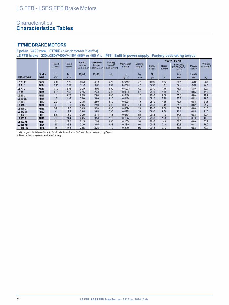
IFT/NIE BRAKE MOTORS 2 poles - 3000 rpm - IFT/NIE (except motors in italics)LS FFB brake - 230∆/380Y/400Y/415Y-460Y or 400 V ∆ - IP55 - Built-in power supply - Factory-set braking torque
Motor typeBrake type
Rated power
Rated torque
Starting torque/
Rated torque
Maximum torque/
Rated torque
Starting current/
Rated current
Moment of inertia
Braking torque1
400 V - 50 HzWeight
IM B3/B52Rated speed
Rated current
EfficiencyIEC 60034-2-1
2007
Power factor
Pn Mn Md/Mn Mm/Mn Id/In J Mf Nn In η% Cos φkW N.m kg.m2 N.m rpm A 4/4 4/4 kg
LS FFB - LSES FFB Brake Motors
CharacteristicsCharacteristics Tables
LS 71 M FFB1 0.37 1.26 3.30 3.14 5.20 0.00060 4.5 2800 0.98 50.0 0.60 9.4LS 71 L FFB1 0.55 1.88 3.24 2.91 5.98 0.00066 4.5 2800 1.32 68.4 0.80 10.3LS 71 L FFB1 0.75 2.58 3.29 3.92 6.00 0.00079 4.5 2780 1.70 75.7 0.80 12.1LS 80 L FFB1 0.75 2.55 2.15 2.40 5.05 0.00096 4.5 2820 1.75 73.0 0.85 11.2LS 80 L FFB1 1.1 3.70 2.35 2.60 5.30 0.00116 12 2830 2.50 75.0 0.84 12.7LS 90 SL FFB1 1.5 4.95 2.50 3.00 6.10 0.00166 12 2880 3.35 77.2 0.84 16.5LS 90 L FFB2 2.2 7.30 2.75 2.90 6.10 0.00294 19 2870 4.65 79.7 0.86 21.8LS 100 L FFB2 3 10.0 2.85 2.90 6.00 0.00304 19 2860 6.45 81.5 0.82 25.7LS 100 L FFB2 3.7 12.2 3.65 3.90 8.05 0.00374 26 2905 7.80 82.7 0.83 31.0LS 112 M FFB2 4 13.2 3.55 3.55 7.90 0.00374 26 2890 8.20 83.1 0.85 31.0LS 132 S FFB3 5.5 18.0 2.30 3.15 7.35 0.00874 52 2925 11.0 84.7 0.85 42.4LS 132 S FFB3 7.5 24.4 2.65 3.50 7.70 0.01044 52 2930 15.8 86.5 0.79 46.0LS 132 M FFB4 9 29.3 2.15 2.95 6.55 0.01688 96 2935 18.0 86.8 0.83 65.2LS 160 MP FFB4 11 35.8 2.20 3.05 6.65 0.01846 96 2935 22.4 87.6 0.81 76.2LS 160 LR FFB4 15 48.8 2.65 3.25 7.70 0.02086 96 2935 28.3 88.7 0.86 87.0
1. Values given for information only; for standards-related restrictions, please consult Leroy-Somer.2. These values are given for information only.
21LS FFB - LSES FFB Brake Motors - 5329 en - 2015.10 / b
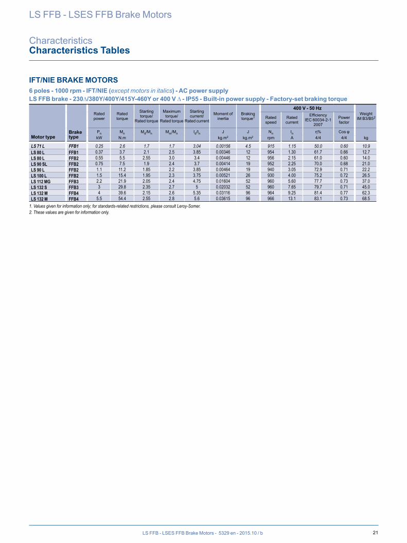
IFT/NIE BRAKE MOTORS 6 poles - 1000 rpm - IFT/NIE (except motors in italics) - AC power supplyLS FFB brake - 230∆/380Y/400Y/415Y-460Y or 400 V ∆ - IP55 - Built-in power supply - Factory-set braking torque
Motor typeBrake type
Rated power
Rated torque
Starting torque/
Rated torque
Maximum torque/
Rated torque
Starting current/
Rated current
Moment of inertia
Braking torque1
400 V - 50 HzWeight
IM B3/B52Rated speed
Rated current
EfficiencyIEC 60034-2-1
2007
Power factor
Pn Mn Md/Mn Mm/Mn Id/In J J Nn In η% Cos φkW N.m kg.m2 kg.m2 rpm A 4/4 4/4 kg
LS FFB - LSES FFB Brake Motors
CharacteristicsCharacteristics Tables
LS 71 L FFB1 0.25 2.6 1.7 1.7 3.04 0.00156 4.5 915 1.15 50.0 0.60 10.9LS 80 L FFB1 0.37 3.7 2.1 2.5 3.85 0.00346 12 954 1.30 61.7 0.66 12.7LS 80 L FFB2 0.55 5.5 2.55 3.0 3.4 0.00446 12 956 2.15 61.0 0.60 14.0LS 90 SL FFB2 0.75 7.5 1.9 2.4 3.7 0.00414 19 952 2.25 70.0 0.68 21.0LS 90 L FFB2 1.1 11.2 1.85 2.2 3.85 0.00464 19 940 3.05 72.9 0.71 22.2LS 100 L FFB2 1.5 15.4 1.95 2.3 3.75 0.00521 26 930 4.00 75.2 0.72 26.5LS 112 MG FFB3 2.2 21.9 2.05 2.4 4.75 0.01604 52 960 5.60 77.7 0.73 37.0LS 132 S FFB3 3 29.8 2.35 2.7 5 0.02032 52 960 7.65 79.7 0.71 45.0LS 132 M FFB4 4 39.6 2.15 2.6 5.35 0.03116 96 964 9.25 81.4 0.77 62.3LS 132 M FFB4 5.5 54.4 2.55 2.8 5.6 0.03615 96 966 13.1 83.1 0.73 68.5
1. Values given for information only; for standards-related restrictions, please consult Leroy-Somer.2. These values are given for information only.
22 LS FFB - LSES FFB Brake Motors - 5329 en - 2015.10 / b
LS FFB - LSES FFB Brake Motors
CharacteristicsCharacteristics Tables
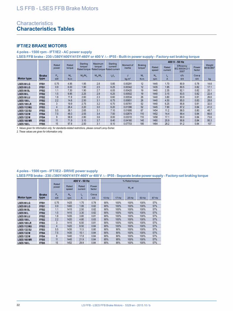
IFT/IE2 BRAKE MOTORS 4 poles - 1500 rpm - IFT/IE2 - AC power supplyLSES FFB brake - 230∆/380Y/400Y/415Y-460Y or 400 V ∆ - IP55 - Built-in power supply - Factory-set braking torque
Motor typeBrake type
Rated power
Rated torque
Starting torque/
Rated torque
Maximum torque/
Rated torque
Starting current/
Rated current
Moment of inertia
Braking torque1
400 V - 50 HzWeight
IM B3/B52Rated speed
Rated current
EfficiencyIEC 60034-2-1
2007
Power factor
Pn Mn Md/Mn Mm/Mn Id/In J Mf Nn In η% Cos φkW N.m kg.m2 N.m rpm A 4/4 4/4 kg
4 poles - 1500 rpm - IFT/IE2 - DRIVE power supplyLSES FFB brake - 230∆/380Y/400Y/415Y-460Y or 400 V ∆ - IP55 - Separate brake power supply - Factory-set braking torque
Motor typeBrake type
Rated power
400 V - 50 Hz % Rated torque
Rated speed
Rated current
Power factor Mn at
Pn Nn In Cos φkW rpm A 4/4 10 Hz 17 Hz 25 Hz 50 Hz 87 Hz
LSES 80 LG FFB1 0.75 4.95 1.95 2.8 5.85 0.00291 12 1445 1.70 80.9 0.78 14.6LSES 80 LG FFB1 0.9 6.00 1.90 2.5 6.25 0.00342 12 1435 1.95 80.5 0.82 17.1LSES 90 SL FFB2 1.1 7.30 1.90 2.7 6.05 0.00420 19 1440 2.35 82.1 0.82 20.1LSES 90 L FFB2 1.5 9.95 2.25 2.9 6.25 0.00502 19 1440 3.15 83.5 0.82 22.4LSES 90 LU FFB2 1.8 11.9 2.60 2.3 6.60 0.00534 26 1440 3.80 83.9 0.81 26.6LSES 100 L FFB2 2.2 14.6 2.50 3.1 6.75 0.00651 26 1440 4.50 85.0 0.83 28.8LSES 100 LR FFB3 3 19.9 2.75 3.2 6.70 0.00761 52 1440 6.25 85.8 0.81 32.0LSES 112 MU FFB3 4 26.4 2.20 3.0 6.20 0.01396 52 1445 7.90 87.2 0.84 41.0LSES 132 SU FFB3 5.5 36.1 2.65 3.1 7.10 0.01695 67 1454 11.2 88.5 0.80 48.7LSES 132 M FFB4 7.5 49.3 2.55 3.4 7.50 0.02874 110 1452 14.4 89.4 0.84 66.6LSES 132 M FFB4 9 58.9 2.80 3.6 8.00 0.03310 110 1458 17.1 90.0 0.84 73.6LSES 160 MR FFB5 11 71.9 3.10 3.7 8.40 0.04160 140 1460 20.9 90.6 0.84 95.3LSES 160 L FFB5 15 97.8 2.50 3.1 8.10 0.07703 180 1464 28.2 91.2 0.84 107
1. Values given for information only; for standards-related restrictions, please consult Leroy-Somer.2. These values are given for information only.
LSES 80 LG FFB1 0.75 1425 1.75 0.78 90% 100% 100% 100% 57%LSES 80 LG FFB1 0.9 1400 1.95 0.82 90% 100% 100% 100% 57%LSES 90 SL FFB2 1.1 1415 2.50 0.82 90% 100% 100% 100% 57%LSES 90 L FFB2 1.5 1415 3.30 0.82 90% 100% 100% 100% 57%LSES 90 LU FFB2 1.8 1435 3.80 0.81 90% 100% 100% 100% 57%LSES 100 L FFB2 2.2 1420 4.80 0.83 90% 100% 100% 100% 57%LSES 100 LR FFB3 3 1415 6.50 0.81 90% 100% 100% 100% 57%LSES 112 MU FFB3 4 1420 8.50 0.84 90% 100% 100% 100% 57%LSES 132 SU FFB3 5.5 1435 11.5 0.80 90% 90% 100% 100% 57%LSES 132 M FFB4 7.5 1435 15.1 0.84 90% 90% 100% 100% 57%LSES 132 M FFB4 9 1440 17.8 0.84 90% 90% 100% 100% 57%LSES 160 MR FFB5 11 1445 21.9 0.84 85% 95% 100% 100% 57%LSES 160 L FFB5 15 1452 29.9 0.84 85% 95% 100% 100% 57%
23LS FFB - LSES FFB Brake Motors - 5329 en - 2015.10 / b
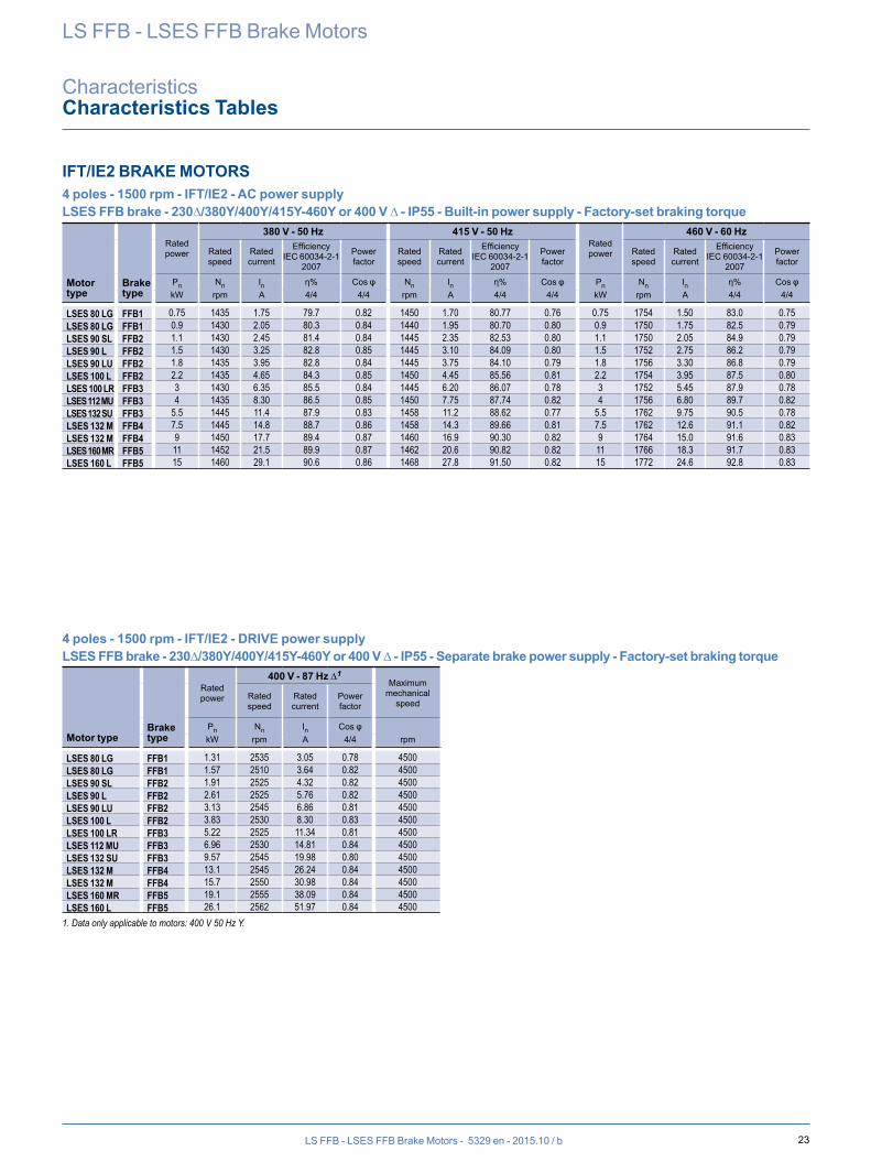
IFT/IE2 BRAKE MOTORS 4 poles - 1500 rpm - IFT/IE2 - AC power supplyLSES FFB brake - 230∆/380Y/400Y/415Y-460Y or 400 V ∆ - IP55 - Built-in power supply - Factory-set braking torque
Motor type
Brake type
Rated power
380 V - 50 Hz 415 V - 50 HzRated power
460 V - 60 Hz
Rated speed
Rated current
EfficiencyIEC 60034-2-1
2007
Power factor
Rated speed
Rated current
EfficiencyIEC 60034-2-1
2007
Power factor
Rated speed
Rated current
EfficiencyIEC 60034-2-1
2007
Power factor
Pn Nn In η% Cos φ Nn In η% Cos φ Pn Nn In η% Cos φkW rpm A 4/4 4/4 rpm A 4/4 4/4 kW rpm A 4/4 4/4
4 poles - 1500 rpm - IFT/IE2 - DRIVE power supplyLSES FFB brake - 230∆/380Y/400Y/415Y-460Y or 400 V ∆ - IP55 - Separate brake power supply - Factory-set braking torque
Motor typeBrake type
Rated power
400 V - 87 Hz ∆1Maximum
mechanical speed
Rated speed
Rated current
Power factor
Pn Nn In Cos φkW rpm A 4/4 rpm
LS FFB - LSES FFB Brake Motors
CharacteristicsCharacteristics Tables
LSES 80 LG FFB1 0.75 1435 1.75 79.7 0.82 1450 1.70 80.77 0.76 0.75 1754 1.50 83.0 0.75LSES 80 LG FFB1 0.9 1430 2.05 80.3 0.84 1440 1.95 80.70 0.80 0.9 1750 1.75 82.5 0.79LSES 90 SL FFB2 1.1 1430 2.45 81.4 0.84 1445 2.35 82.53 0.80 1.1 1750 2.05 84.9 0.79LSES 90 L FFB2 1.5 1430 3.25 82.8 0.85 1445 3.10 84.09 0.80 1.5 1752 2.75 86.2 0.79LSES 90 LU FFB2 1.8 1435 3.95 82.8 0.84 1445 3.75 84.10 0.79 1.8 1756 3.30 86.8 0.79LSES 100 L FFB2 2.2 1435 4.65 84.3 0.85 1450 4.45 85.56 0.81 2.2 1754 3.95 87.5 0.80LSES 100 LR FFB3 3 1430 6.35 85.5 0.84 1445 6.20 86.07 0.78 3 1752 5.45 87.9 0.78LSES 112 MU FFB3 4 1435 8.30 86.5 0.85 1450 7.75 87.74 0.82 4 1756 6.80 89.7 0.82LSES 132 SU FFB3 5.5 1445 11.4 87.9 0.83 1458 11.2 88.62 0.77 5.5 1762 9.75 90.5 0.78LSES 132 M FFB4 7.5 1445 14.8 88.7 0.86 1458 14.3 89.66 0.81 7.5 1762 12.6 91.1 0.82LSES 132 M FFB4 9 1450 17.7 89.4 0.87 1460 16.9 90.30 0.82 9 1764 15.0 91.6 0.83LSES 160 MR FFB5 11 1452 21.5 89.9 0.87 1462 20.6 90.82 0.82 11 1766 18.3 91.7 0.83LSES 160 L FFB5 15 1460 29.1 90.6 0.86 1468 27.8 91.50 0.82 15 1772 24.6 92.8 0.83
LSES 80 LG FFB1 1.31 2535 3.05 0.78 4500LSES 80 LG FFB1 1.57 2510 3.64 0.82 4500LSES 90 SL FFB2 1.91 2525 4.32 0.82 4500LSES 90 L FFB2 2.61 2525 5.76 0.82 4500LSES 90 LU FFB2 3.13 2545 6.86 0.81 4500LSES 100 L FFB2 3.83 2530 8.30 0.83 4500LSES 100 LR FFB3 5.22 2525 11.34 0.81 4500LSES 112 MU FFB3 6.96 2530 14.81 0.84 4500LSES 132 SU FFB3 9.57 2545 19.98 0.80 4500LSES 132 M FFB4 13.1 2545 26.24 0.84 4500LSES 132 M FFB4 15.7 2550 30.98 0.84 4500LSES 160 MR FFB5 19.1 2555 38.09 0.84 4500LSES 160 L FFB5 26.1 2562 51.97 0.84 4500
1. Data only applicable to motors: 400 V 50 Hz Y.
24 LS FFB - LSES FFB Brake Motors - 5329 en - 2015.10 / b
LS FFB - LSES FFB Brake Motors
CharacteristicsCharacteristics Tables
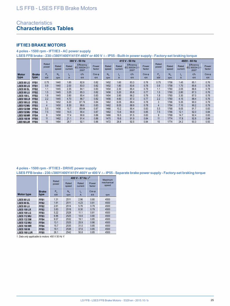
IFT/IE3 BRAKE MOTORS 4 poles - 1500 rpm - IFT/IE3 - AC power supplyLSES FFB brake - 230∆/380Y/400Y/415Y-460Y or 400 V ∆ - IP55 - Built-in power supply - Factory-set braking torque
Motor typeBrake type
Rated power
Rated torque
Starting torque/
Rated torque
Maximum torque/
Rated torque
Starting current/
Rated current
Moment of inertia
Braking torque1
400 V - 50 HzWeight
IM B3/B52Rated speed
Rated current
EfficiencyIEC 60034-2-1
2007
Power factor
Pn Mn Md/Mn Mm/Mn Id/In J Mf Nn In η% Cos φkW N.m kg.m2 N.m rpm A 4/4 4/4 kg
4 poles - 1500 rpm - IFT/IE3 - DRIVE power supplyLSES FFB brake - 230∆/380Y/400Y/415Y-460Y or 400 V ∆ - IP55 - Separate brake power supply - Factory-set braking torque
Motor typeBrake type
Rated power
400 V - 50 Hz % Rated torque
Rated speed
Rated current
Power factor Mn at
Pn Nn In Cos φkW rpm A 4/4 10 Hz 17 Hz 25 Hz 50 Hz 87 Hz
LSES 80 LG FFB1 0.75 4.95 2.20 2.9 6.20 0.0036 12 1450 1.65 83.2 0.80 16.6LSES 80 LG FFB1 0.9 5.90 2.58 3.1 6.42 0.0041 12 1450 1.90 83.5 0.80 17.1LSES 90 SL FFB2 1.1 7.25 2.45 3.2 6.90 0.0050 19 1450 2.30 84.8 0.81 22.4LSES 90 LU FFB2 1.5 9.85 2.90 3.7 7.65 0.0061 19 1452 3.20 85.6 0.79 26.6LSES 100 L FFB2 1.8 11.8 2.40 2.7 6.59 0.0065 26 1452 3.70 86.0 0.82 28.8LSES 100 LR FFB2 2.2 14.4 3.20 3.8 8.05 0.0076 26 1454 4.60 87.1 0.79 32.0LSES 100 LG FFB3 3 19.6 2.45 3.3 7.15 0.0124 52 1460 6.05 88.3 0.81 37.6LSES 112 MU FFB3 4 26.2 2.70 3.1 7.05 0.0140 52 1458 8.10 88.8 0.80 43.6LSES 132 SM FFB4 5.5 35.9 2.80 3.6 8.55 0.0287 69 1462 10.3 90.3 0.85 66.5LSES 132 MU FFB4 7.5 49.1 2.95 3.4 8.00 0.0355 110 1458 14.0 90.6 0.86 77.1LSES 160 MR FFB4 9 58.7 3.10 3.7 8.85 0.0416 110 1464 16.7 91.2 0.85 92.3LSES 160 M FFB5 11 71.7 2.25 3.1 7.25 0.0770 140 1466 20.5 91.6 0.85 110LSES 160 LUR FFB5 15 97.6 2.55 3.5 8.35 0.1012 180 1468 27.7 92.3 0.85 117
1. Values given for information only; for standards-related restrictions, please consult Leroy-Somer.2. These values are given for information only.
LSES 80 LG FFB1 0.75 1450 1.70 0.80 90% 100% 100% 100% 83%LSES 90 SL FFB2 1.1 1450 2.43 0.81 90% 100% 100% 100% 83%LSES 90 LU FFB2 1.5 1452 3.31 0.79 90% 100% 100% 100% 83%LSES 100 LR FFB2 2.2 1454 4.77 0.79 90% 100% 100% 100% 83%LSES 100 LG FFB3 3 1460 6.37 0.81 90% 100% 100% 100% 83%LSES 112 MU FFB3 4 1458 8.37 0.80 90% 100% 100% 100% 83%LSES 132 SM FFB4 5.5 1462 11.0 0.85 90% 90% 100% 100% 83%LSES 132 MU FFB4 7.5 1458 14.9 0.86 90% 90% 100% 100% 83%LSES 160 MR FFB4 9 1464 17.8 0.85 90% 90% 100% 100% 83%LSES 160 M FFB5 11 1466 21.6 0.85 85% 95% 100% 100% 83%LSES 160 LUR FFB5 15 1468 29.2 0.85 85% 95% 100% 100% 83%
25LS FFB - LSES FFB Brake Motors - 5329 en - 2015.10 / b
IFT/IE3 BRAKE MOTORS 4 poles - 1500 rpm - IFT/IE3 - AC power supplyLSES FFB brake - 230∆/380Y/400Y/415Y-460Y or 400 V ∆ - IP55 - Built-in power supply - Factory-set braking torque
Motor type
Brake type
Rated power
380 V - 50 Hz 415 V - 50 HzRated power
460V - 60 Hz
Rated speed
Rated current
EfficiencyIEC 60034-2-1
2007
Power factor
Rated speed
Rated current
EfficiencyIEC 60034-2-1
2007
Power factor
Rated speed
Rated current
EfficiencyIEC 60034-2-1
2007
Power factor
Pn Nn In η% Cos φ Nn In η% Cos φ Pn Nn In η% Cos φkW rpm A 4/4 4/4 rpm A 4/4 4/4 kW rpm A 4/4 4/4
4 poles - 1500 rpm - IFT/IE3 - DRIVE power supplyLSES FFB brake - 230∆/380Y/400Y/415Y-460Y or 400 V ∆ - IP55 - Separate brake power supply - Factory-set braking torque
Motor typeBrake type
Rated power
400 V - 87 Hz ∆1Maximum
mechanical speed
Rated speed
Rated current
Power factor
Pn Nn In Cos φkW rpm A 4/4 rpm
LS FFB - LSES FFB Brake Motors
CharacteristicsCharacteristics Tables
LSES 80 LG FFB1 0.75 1440 1.65 82.6 0.82 1452 1.60 83.3 0.78 0.75 1758 1.45 85.1 0.76LSES 80 LG FFB1 0.9 1440 2.00 83.0 0.82 1452 1.80 83.6 0.78 0.9 1758 1.70 85.6 0.76LSES 90 SL FFB2 1.1 1445 2.35 84.1 0.83 1454 2.30 85.4 0.79 1.1 1760 2.05 86.6 0.78LSES 90 LU FFB2 1.5 1445 3.25 85.3 0.82 1456 3.20 85.8 0.77 1.5 1760 2.80 87.3 0.76LSES 100 L FFB2 1.8 1445 3.90 85.4 0.83 1454 3.90 86.2 0.79 1.8 1760 3.30 87.0 0.78LSES 100 LR FFB2 2.2 1445 4.70 86.7 0.82 1456 4.60 87.3 0.77 2.2 1760 4.15 88.4 0.76LSES 100 LG FFB3 3 1452 6.20 87.74 0.84 1462 6.05 88.4 0.78 3 1766 5.35 90.0 0.79LSES 112 MU FFB3 4 1450 8.30 88.6 0.83 1462 8.05 88.9 0.78 4 1764 7.10 90.2 0.79LSES 132 SM FFB4 5.5 1456 10.7 89.64 0.87 1466 10.2 90.4 0.83 5.5 1768 9.05 91.7 0.83LSES 132 MU FFB4 7.5 1450 14.5 90.4 0.87 1462 13.6 90.9 0.85 7.5 1766 12.1 92.0 0.84LSES 160 MR FFB4 9 1458 17.4 90.6 0.86 1466 16.5 91.5 0.83 9 1768 14.7 92.4 0.83LSES 160 M FFB5 11 1462 21.1 91.4 0.86 1470 19.8 91.9 0.84 11 1774 17.8 92.8 0.84LSES 160 LUR FFB5 15 1464 28.7 92.1 0.86 1472 26.8 92.5 0.84 15 1774 24.2 93.3 0.93
LSES 80 LG FFB1 1.31 2511 2.96 0.80 4500LSES 90 SL FFB2 1.91 2511 4.23 0.81 4500LSES 90 LU FFB2 2.61 2514 5.76 0.79 4500LSES 100 LR FFB2 3.83 2518 8.30 0.79 4500LSES 100 LG FFB3 5.22 2528 11.1 0.81 4500LSES 112 MU FFB3 6.96 2525 14.6 0.80 4500LSES 132 SM FFB4 9.57 2532 19.1 0.85 4500LSES 132 MU FFB4 13.1 2525 25.9 0.86 4500LSES 160 MR FFB4 15.7 2535 31.0 0.85 4500LSES 160 M FFB5 19.1 2538 37.6 0.85 4500LSES 160 LUR FFB5 26.1 2542 50.8 0.85 4500
1. Data only applicable to motors: 400 V 50 Hz Y.
26 LS FFB - LSES FFB Brake Motors - 5329 en - 2015.10 / b
LS FFB - LSES FFB Brake Motors
CharacteristicsCharacteristics Tables
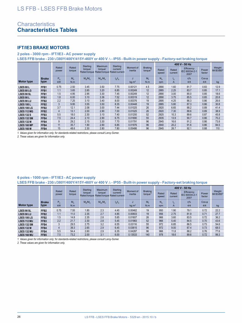
IFT/IE3 BRAKE MOTORS 2 poles - 3000 rpm - IFT/IE3 - AC power supplyLSES FFB brake - 230∆/380Y/400Y/415Y-460Y or 400 V ∆ - IP55 - Built-in power supply - Factory-set braking torque
Motor typeBrake type
Rated power
Rated torque
Starting torque/
Rated torque
Maximum torque/
Rated torque
Starting current/
Rated current
Moment of inertia
Braking torque1
400 V - 50 HzWeight
IM B3/B52Rated speed
Rated current
EfficiencyIEC 60034-2-1
2007
Power factor
Pn Mn Md/Mn Mm/Mn Id/In J Mf Nn In η% Cos φkW N.m kg.m2 N.m rpm A 4/4 4/4 kg
LSES 80 L FFB1 0.75 2.50 3.45 3.50 7.75 0.00121 4.5 2890 1.60 81.7 0.83 12.9LSES 80 LG FFB1 1.1 3.65 2.65 3.20 6.85 0.00249 12 2885 2.25 83.7 0.85 17.1LSES 90 SL FFB1 1.5 4.95 2.95 3.30 7.45 0.00249 12 2890 3.00 85.0 0.85 18.6LSES 90 L FFB1 1.8 6.00 3.10 3.36 7.52 0.00319 12 2890 3.75 85.5 0.85 20.8LSES 90 LU FFB2 2.2 7.25 3.10 3.40 8.00 0.00376 19 2895 4.25 86.3 0.86 26.6LSES 100 L FFB2 3 9.95 3.55 3.50 8.35 0.00448 19 2885 5.80 87.3 0.86 30.8LSES 100 LG FFB2 3.7 12.1 2.08 3.00 7.44 0.01025 26 2920 6.65 88.2 0.89 41.4LSES 112 MG FFB2 4 13.1 2.00 2.90 7.00 0.01025 26 2920 7.30 88.6 0.89 38.9LSES 132 S FFB3 5.5 18.0 2.30 3.10 7.40 0.01200 52 2925 10.3 89.6 0.87 45.8LSES 132 SM FFB4 7.5 24.4 2.10 2.90 6.75 0.01690 55 2935 13.9 90.7 0.86 70.2LSES 132 M FFB4 9 29.2 2.15 3.30 7.70 0.01791 96 2945 16.6 91.2 0.86 73.8LSES 160 MP FFB4 11 35.7 1.90 2.90 6.85 0.01976 96 2940 20.2 91.6 0.86 84.5LSES 160 M FFB4 15 48.6 2.30 2.80 7.80 0.05486 96 2945 26.7 92.1 0.88 110
1. Values given for information only; for standards-related restrictions, please consult Leroy-Somer.2. These values are given for information only.
LSES 90 SL FFB2 0.75 7.55 1.85 2.3 4.45 0.00462 19 950 1.90 79.1 0.72 22.2LSES 90 LU FFB2 1.1 11.0 2.35 2.7 4.85 0.00603 19 956 2.75 81.9 0.71 27.7LSES 100 LG FFB2 1.5 14.8 2.35 2.8 5.65 0.01607 26 966 3.60 83.5 0.72 36.2LSES 112 MU FFB3 2.2 21.7 2.30 2.8 5.45 0.01983 52 966 5.40 84.5 0.70 43.6LSES 132 SM FFB4 3 29.5 2.75 3.2 6.55 0.03116 55 972 6.85 86.5 0.73 54.6LSES 132 M FFB4 4 39.3 2.65 2.9 6.45 0.03615 96 972 9.00 87.4 0.73 68.5LSES 132 MU FFB4 5.5 54.4 2.60 2.9 6.35 0.04287 96 966 11.8 88.2 0.76 77.6LSES 160 MU FFB5 7.5 73.2 2.00 3.1 6.00 0.13533 140 978 18.6 89.6 0.72 99.3
1. Values given for information only; for standards-related restrictions, please consult Leroy-Somer.2. These values are given for information only.
6 poles - 1000 rpm - IFT/IE3 - AC power supplyLSES FFB brake - 230∆/380Y/400Y/415Y-460Y or 400 V ∆ - IP55 - Built-in power supply - Factory-set braking torque
Motor typeBrake type
Rated power
Rated torque
Starting torque/
Rated torque
Maximum torque/
Rated torque
Starting current/
Rated current
Moment of inertia
Braking torque1
400 V - 50 HzWeight
IM B3/B52Rated speed
Rated current
EfficiencyIEC 60034-2-1
2007
Power factor
Pn Mn Md/Mn Mm/Mn Id/In J Mf Nn In η% Cos φkW N.m kg.m2 N.m rpm A 4/4 4/4 kg
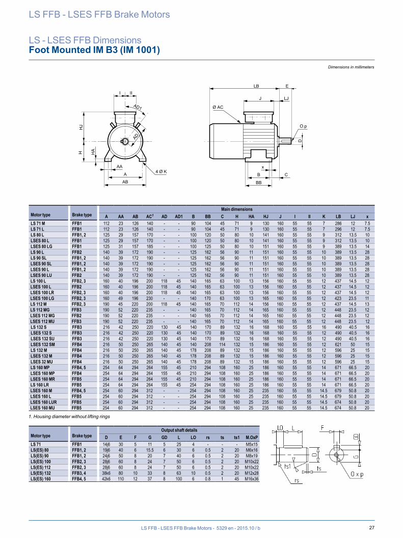
27
Ø AC
x
B C
BB
AD
LB
LJJ
E
O.p
D
I IIH
AHH
J
A
AB
AA
AD1
4 Ø K
LS FFB - LSES FFB Brake Motors - 5329 en - 2015.10 / b
Dimensions in millimeters
LS FFB - LSES FFB Brake Motors
LS - LSES FFB DimensionsFoot Mounted IM B3 (IM 1001)
Motor type Brake typeMain dimensions
A AA AB AC1 AD AD1 B BB C H HA HJ J I II K LB LJ xLS 71 M FFB1 112 23 126 140 - - 90 104 45 71 9 130 160 55 55 7 286 12 7.5LS 71 L FFB1 112 23 126 140 - - 90 104 45 71 9 130 160 55 55 7 296 12 7.5LS 80 L FFB1, 2 125 29 157 170 - - 100 120 50 80 10 141 160 55 55 9 312 13.5 10LSES 80 L FFB1 125 29 157 170 - - 100 120 50 80 10 141 160 55 55 9 312 13.5 10LSES 80 LG FFB1 125 31 157 185 - - 100 125 50 80 10 151 160 55 55 9 389 13.5 14LS 90 L FFB2 140 39 172 190 - - 125 162 56 90 11 151 160 55 55 10 389 13.5 28LS 90 SL FFB1, 2 140 39 172 190 - - 125 162 56 90 11 151 160 55 55 10 389 13.5 28LSES 90 SL FFB1, 2 140 39 172 190 - - 125 162 56 90 11 151 160 55 55 10 389 13.5 28LSES 90 L FFB1, 2 140 39 172 190 - - 125 162 56 90 11 151 160 55 55 10 389 13.5 28LSES 90 LU FFB2 140 39 172 190 - - 125 162 56 90 11 151 160 55 55 10 389 13.5 28LS 100 L FFB2, 3 160 40 196 200 118 45 140 165 63 100 13 156 160 55 55 12 437 14.5 12LSES 100 L FFB2 160 40 196 200 118 45 140 165 63 100 13 156 160 55 55 12 437 14.5 12LSES 100 LR FFB2, 3 160 40 196 200 118 45 140 165 63 100 13 156 160 55 55 12 437 14.5 12LSES 100 LG FFB2, 3 160 49 196 230 - - 140 170 63 100 13 165 160 55 55 12 423 23.5 11LS 112 M FFB2, 3 190 45 220 200 118 45 140 165 70 112 14 156 160 55 55 12 437 14.5 13LS 112 MG FFB3 190 52 220 235 - - 140 165 70 112 14 165 160 55 55 12 448 23.5 12LSES 112 MG FFB2 190 52 220 235 - - 140 165 70 112 14 165 160 55 55 12 448 23.5 12LSES 112 MU FFB3 190 52 220 235 - - 140 165 70 112 14 165 160 55 55 12 448 23.5 12LS 132 S FFB3 216 42 250 220 130 45 140 170 89 132 16 168 160 55 55 16 490 40.5 16LSES 132 S FFB3 216 42 250 220 130 45 140 170 89 132 16 168 160 55 55 12 490 40.5 16LSES 132 SU FFB3 216 42 250 220 130 45 140 170 89 132 16 168 160 55 55 12 490 40.5 16LSES 132 SM FFB4 216 50 250 265 140 45 140 208 114 132 15 186 160 55 55 12 621 50 15LS 132 M FFB4 216 50 250 265 140 45 178 208 89 132 15 186 160 55 55 12 596 25 15LSES 132 M FFB4 216 50 250 265 140 45 178 208 89 132 15 186 160 55 55 12 596 25 15LSES 32 MU FFB4 216 50 250 265 140 45 178 208 89 132 15 186 160 55 55 12 596 25 15LS 160 MP FFB4, 5 254 64 294 264 155 45 210 294 108 160 25 186 160 55 55 14 671 66.5 20LSES 160 MP FFB4 254 64 294 264 155 45 210 294 108 160 25 186 160 55 55 14 671 66.5 20LSES 160 MR FFB5 254 64 294 264 155 45 210 294 108 160 25 186 160 55 55 14 671 66.5 20LS 160 LR FFB5 254 64 294 264 155 45 254 294 108 160 25 186 160 55 55 14 671 66.5 20LSES 160 M FFB4, 5 254 60 294 312 - - 254 294 108 160 25 235 160 55 55 14.5 679 50.8 20LSES 160 L FFB5 254 60 294 312 - - 254 294 108 160 25 235 160 55 55 14.5 679 50.8 20LSES 160 LUR FFB5 254 60 294 312 - - 254 294 108 160 25 235 160 55 55 14.5 674 50.8 20LSES 160 MU FFB5 254 60 294 312 - - 254 294 108 160 25 235 160 55 55 14.5 674 50.8 20
1. Housing diameter without lifting rings
Motor type Brake typeOutput shaft details
D E F G GD L LO rs ts ts1 M.OxPLS 71 FFB1 14j6 30 5 11 5 25 4 - - - M5x15LS(ES) 80 FFB1, 2 19j6 40 6 15.5 6 30 6 0.5 2 20 M6x16LS(ES) 90 FFB1, 2 24j6 50 8 20 7 40 6 0.5 2 20 M8x19LS(ES) 100 FFB2, 3 28j6 60 8 24 7 50 6 0.5 2 20 M10x22LS(ES) 112 FFB2, 3 28j6 60 8 24 7 50 6 0.5 2 20 M10x22LS(ES) 132 FFB3, 4 38k6 80 10 33 8 63 10 0.5 2 20 M12x28LS(ES) 160 FFB4, 5 42k6 110 12 37 8 100 6 0.8 1 45 M16x36
DIMENSIONSFoot Mounted LS, LSES FFB
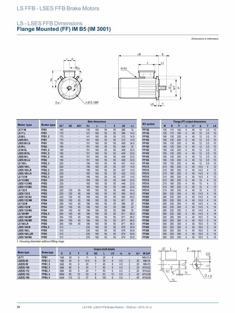
28
n Ø S / ØM
N Pj6
α
AD
AD1
LA
J LJ
T
Ø AC
LB E
D
O.p
III
HJ
LS FFB - LSES FFB Brake Motors - 5329 en - 2015.10 / b
Dimensions in millimeters
LS FFB - LSES FFB Brake Motors
LS - LSES FFB DimensionsFlange Mounted (FF) IM B5 (IM 3001)
Main dimensionsIEC symbol
Flange (FF) output dimensionsMotor type Brake type AC1 AD AD1 HJ J I II LB LJ M N P n α° S T LALS 71 M FFB1 140 - - 130 160 55 55 286 12 FF130 130 110 160 4 45 10 3.5 10LS 71 L FFB1 170 - - 141 160 55 55 296 14.5 FF130 130 110 160 4 45 10 3.5 10LS 80 L FFB1, 2 170 - - 141 160 55 55 312 14.5 FF165 165 130 200 4 45 12 3.5 10LSES 80 L FFB1 170 - - 141 160 55 55 312 13.5 FF165 165 130 200 4 45 12 3.5 10LSES 80 LG FFB1 185 - - 151 160 55 55 409 34.5 FF165 165 130 200 4 45 12 3.5 10LS 90 L FFB2 190 - - 151 160 55 55 409 33 FF165 165 130 200 4 45 12 3.5 10LS 90 SL FFB1, 2 190 - - 151 160 55 55 409 33.5 FF165 165 130 200 4 45 12 3.5 10LSES 90 SL FFB1, 2 190 - - 151 160 55 55 409 33.5 FF165 165 130 200 4 45 12 3.5 10LSES 90 L FFB1, 2 190 - - 151 160 55 55 409 33.5 FF165 165 130 200 4 45 12 3.5 10LSES 90 LU FFB2 190 - - 151 160 55 55 409 33.5 FF165 165 130 200 4 45 12 3.5 10LS 100 L FFB2, 3 200 - - 156 160 55 55 437 14.5 FF165 165 130 200 4 45 12 3.5 10LSES 100 L FFB2 200 - - 156 160 55 55 437 14.5 FF215 215 180 250 4 45 14.5 4 12LSES 100 LR FFB2, 3 200 - - 156 160 55 55 437 14.5 FF215 215 180 250 4 45 14.5 4 12LSES 100 LG FFB2, 3 235 - - 165 160 55 55 423 13.5 FF215 215 180 250 4 45 14.5 4 12LS 112 M FFB2, 3 200 - - 156 160 55 55 437 14.5 FF215 215 180 250 4 45 14.5 4 12LS 112 MG FFB3 235 - - 165 160 55 55 448 23.5 FF215 215 180 250 4 45 15 4 12LSES 112 MG FFB2 235 - - 165 160 55 55 448 23.5 FF215 215 180 250 4 45 15 4 12LSES 112 MU FFB3 235 - - 165 160 55 55 448 23.5 FF215 215 180 250 4 45 15 4 12LS 132 S FFB3 220 130 45 168 160 55 55 490 40.5 FF215 215 180 250 4 45 15 4 12LSES 132 S FFB3 220 130 45 168 160 55 55 490 40.5 FF265 265 230 300 4 45 14.5 4 14LSES 132 SU FFB3 220 130 45 168 160 55 55 490 40.5 FF265 265 230 300 4 45 14.5 4 14LSES 132 SM FFB4 265 140 45 186 160 55 55 621 50 FF265 265 230 300 4 45 14.5 4 14LS 132 M FFB4 265 140 45 186 160 55 55 596 25 FF265 265 230 300 4 45 14.5 4 14LSES 132 M FFB4 265 140 45 186 160 55 55 596 25 FF265 265 230 300 4 45 14.5 4 14LSES 132 MU FFB4 265 140 45 186 160 55 55 596 25 FF265 265 230 300 4 45 14.5 4 14LS 160 MP FFB4, 5 264 155 45 186 160 55 55 671 66.5 FF265 265 230 300 4 45 14.5 4 14LSES 160 MP FFB4 264 155 45 186 160 55 55 671 66.5 FF300 300 250 350 4 45 18.5 5 14LSES 160 MR FFB5 264 155 45 186 160 55 55 671 66.5 FF300 300 250 350 4 45 18.5 5 14LS 160 LR FFB5 264 155 45 186 160 55 55 671 66.5 FF300 300 250 350 4 45 18.5 5 14LSES 160 M FFB4, 5 312 - - 235 160 55 55 679 50.8 FF300 300 250 350 4 45 18.5 5 14LSES 160 L FFB5 312 - - 235 160 55 55 679 50.8 FF300 300 250 350 4 45 18.5 5 14LSES 160 LUR FFB5 312 - - 235 160 55 55 674 50.8 FF300 300 250 350 4 45 18.5 5 14LSES 160 MU FFB5 312 - - 235 160 55 55 674 50.8 FF300 300 250 350 4 45 18.5 5 14
1. Housing diameter without lifting rings
Motor type Brake typeOutput shaft details
D E F G GD L LO rs ts ts1 M.OxPLS 71 FFB1 14j6 30 5 11 5 25 4 - - - M5x12.4LS(ES) 80 FFB1, 2 19j6 40 6 15.5 6 30 6 0.5 2 20 M6x16LS(ES) 90 FFB1, 2 24j6 50 8 20 7 40 6 0.5 2 20 M8x19LS(ES) 100 FFB2, 3 28j6 60 8 24 7 50 6 0.5 2 20 M10x22LS(ES) 112 FFB2, 3 28j6 60 8 24 7 50 6 0.5 2 20 M10x22LS(ES) 132 FFB3, 4 38k6 80 10 33 8 63 10 0.5 2 20 M12x28LS(ES) 160 FFB4, 5 42k6 110 12 37 8 100 6 0.8 1 45 M16x36
Flange Mounted (FF) LS, LSES FFB
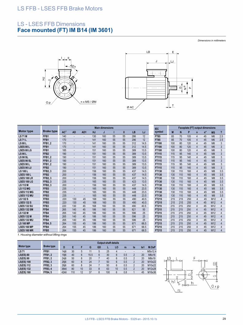
29
N Pj6
Ø AC
n x MS / ØM
AD
HJ
AD1
O.p
D
T
I II
α
LB E
J LJ
LS FFB - LSES FFB Brake Motors - 5329 en - 2015.10 / b
Dimensions in millimeters
LS FFB - LSES FFB Brake Motors
LS - LSES FFB DimensionsFace mounted (FT) IM B14 (IM 3601)
Main dimensions IEC symbol
Faceplate (FT) output dimensionsMotor type Brake type AC1 AD AD1 HJ J I II LB LJ M N P n α° MS TLS 71 M FFB1 140 - - 130 160 55 55 286 12 FT85 85 70 105 4 45 M6 2.5LS 71 L FFB1 170 - - 141 160 55 55 296 12 FT85 85 70 105 4 45 M6 2.5LS 80 L FFB1, 2 170 - - 141 160 55 55 312 14.5 FT100 100 80 120 4 45 M6 3LSES 80 L FFB1 170 - - 141 160 55 55 312 14.5 FT100 100 80 120 4 45 M6 3LSES 80 LG FFB1 185 - - 151 160 55 55 389 13.5 FT100 100 80 120 4 45 M6 3LS 90 L FFB2 190 - - 151 160 55 55 389 13.5 FT115 115 95 140 4 45 M8 3LS 90 SL FFB1, 2 190 - - 151 160 55 55 389 13.5 FT115 115 95 140 4 45 M8 3LSES 90 SL FFB1, 2 190 - - 151 160 55 55 389 13.5 FT115 115 95 140 4 45 M8 3LSES 90 L FFB1, 2 190 - - 151 160 55 55 389 13.5 FT115 115 95 140 4 45 M8 3LSES 90 LU FFB2 190 - - 151 160 55 55 389 13.5 FT115 115 95 140 4 45 M8 3LS 100 L FFB2, 3 200 - - 156 160 55 55 437 14.5 FT130 130 110 160 4 45 M8 3.5LSES 100 L FFB2 200 - - 156 160 55 55 437 14.5 FT130 130 110 160 4 45 M8 3.5LSES 100 LR FFB2, 3 200 - - 156 160 55 55 437 14.5 FT130 130 110 160 4 45 M8 3.5LSES 100 LG FFB2, 3 235 - - 165 160 55 55 423 13.5 FT130 130 110 160 4 45 M8 3.5LS 112 M FFB2, 3 200 - - 156 160 55 55 437 14.5 FT130 130 110 160 4 45 M8 3.5LS 112 MG FFB3 235 - - 165 160 55 55 448 23.5 FT130 130 110 160 4 45 M8 3.5LSES 112 MG FFB2 235 - - 165 160 55 55 448 23.5 FT130 130 110 160 4 45 M8 3.5LSES 112 MU FFB3 235 - - 165 160 55 55 448 23.5 FT130 130 110 160 4 45 M8 3.5LS 132 S FFB3 220 130 45 168 160 55 55 490 40.5 FT215 215 215 250 4 45 M12 4LSES 132 S FFB3 220 130 45 168 160 55 55 490 40.5 FT215 215 215 250 4 45 M12 4LSES 132 SU FFB3 220 130 45 168 160 55 55 490 40.5 FT215 215 215 250 4 45 M12 4LSES 132 SM FFB4 265 140 45 186 160 55 55 621 50 FT215 215 215 250 4 45 M12 4LS 132 M FFB4 265 140 45 186 160 55 55 596 25 FT215 215 215 250 4 45 M12 4LSES 132 M FFB4 265 140 45 186 160 55 55 596 25 FT215 215 215 250 4 45 M12 4LSES 132 MU FFB4 265 140 45 186 160 55 55 596 25 FT215 215 215 250 4 45 M12 4LS 160 MP FFB4, 5 264 155 45 186 160 55 55 671 66.5 FT215 215 215 250 4 45 M12 4LSES 160 MP FFB4 264 155 45 186 160 55 55 671 66.5 FT215 215 215 250 4 45 M12 4LSES 160 MR FFB5 264 155 45 186 160 55 55 671 66.5 FT215 215 215 250 4 45 M12 4
1. Housing diameter without lifting rings
Motor type Brake typeOutput shaft details
D E F G GD L LO rs ts ts1 M.OxPLS 71 FFB1 14j6 30 5 11 5 25 4 - - - M5x12.4LS(ES) 80 FFB1, 2 19j6 40 6 15.5 6 30 6 0.5 2 20 M6x16LS(ES) 90 FFB1, 2 24j6 50 8 20 7 40 6 0.5 2 20 M8x19LS(ES) 100 FFB2, 3 28j6 60 8 24 7 50 6 0.5 2 20 M10x22LS(ES) 112 FFB2, 3 28j6 60 8 24 7 50 6 0.5 2 20 M10x22LS(ES) 132 FFB3, 4 38k6 80 10 33 8 63 10 0.5 2 20 M12x28LS(ES) 160 FFB4, 5 42k6 110 12 37 8 100 6 0.8 1 45 M16x36
Face Mounted (FT) LS, LSES FFB
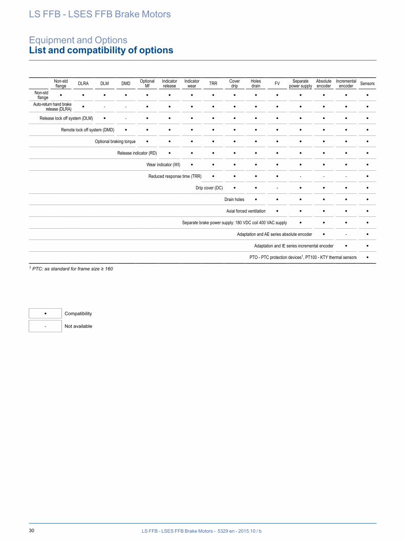
30 LS FFB - LSES FFB Brake Motors - 5329 en - 2015.10 / b
LS FFB - LSES FFB Brake Motors
Equipment and OptionsList and compatibility of options
Non-std flange DLRA DLM DMD Optional
MfIndicatorrelease
Indicatorwear TRR Cover
dripHolesdrain FV Separate
power supplyAbsolute encoder
Incremental encoder Sensors
Non-std flange • • • • • • • • • • • • • • •
Auto-return hand brake release (DLRA) • - - • • • • • • • • • • •
Release lock off system (DLM) • - • • • • • • • • • • •Remote lock off system (DMD) • • • • • • • • • • • •
Optional braking torque • • • • • • • • • • •Release indicator (RD) • • • • • • • • • •
Wear indicator (WI) • • • • • • • • •Reduced response time (TRR) • • • • - - - •
Drip cover (DC) • • - • • • •Drain holes • • • • • •Axial forced ventilation • • • • •
Separate brake power supply: 180 VDC coil 400 VAC supply • • • •Adaptation and AE series absolute encoder • - •
Adaptation and IE series incremental encoder • •PTO - PTC protection devices1, PT100 - KTY thermal sensors •
1 PTC: as standard for frame size ≥ 160
• Compatibility
- Not available
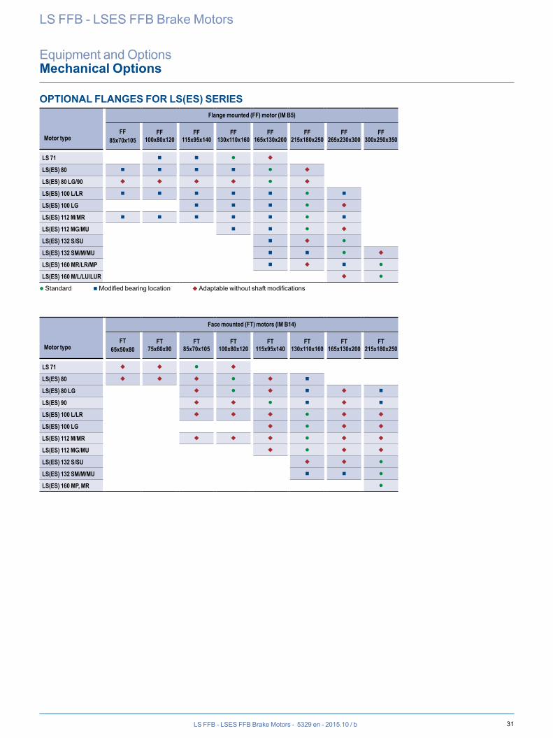
31LS FFB - LSES FFB Brake Motors - 5329 en - 2015.10 / b
OPTIONAL FLANGES FOR LS(ES) SERIES
Motor type
Flange mounted (FF) motor (IM B5)
FF85x70x105
FF100x80x120
FF115x95x140
FF130x110x160
FF165x130x200
FF215x180x250
FF265x230x300
FF300x250x350
LS 71 n n l u
LS(ES) 80 n n n n l u
LS(ES) 80 LG/90 u u u u l u
LS(ES) 100 L/LR n n n n n l n
LS(ES) 100 LG n n n l u
LS(ES) 112 M/MR n n n n n l n
LS(ES) 112 MG/MU n n l u
LS(ES) 132 S/SU n u l
LS(ES) 132 SM/M/MU n n l u
LS(ES) 160 MR/LR/MP n u n l
LS(ES) 160 M/L/LU/LUR u l
l Standard n Modified bearing location u Adaptable without shaft modifications
Motor type
Face mounted (FT) motors (IM B14)
FT65x50x80
FT75x60x90
FT85x70x105
FT100x80x120
FT115x95x140
FT130x110x160
FT165x130x200
FT215x180x250
LS 71 u u l u
LS(ES) 80 u u u l u n
LS(ES) 80 LG u l u n u n
LS(ES) 90 u u l n u n
LS(ES) 100 L/LR u u u l u u
LS(ES) 100 LG u l u u
LS(ES) 112 M/MR u u u l u u
LS(ES) 112 MG/MU u l u u
LS(ES) 132 S/SU u u l
LS(ES) 132 SM/M/MU n n l
LS(ES) 160 MP, MR l
LS FFB - LSES FFB Brake Motors
Equipment and OptionsMechanical Options
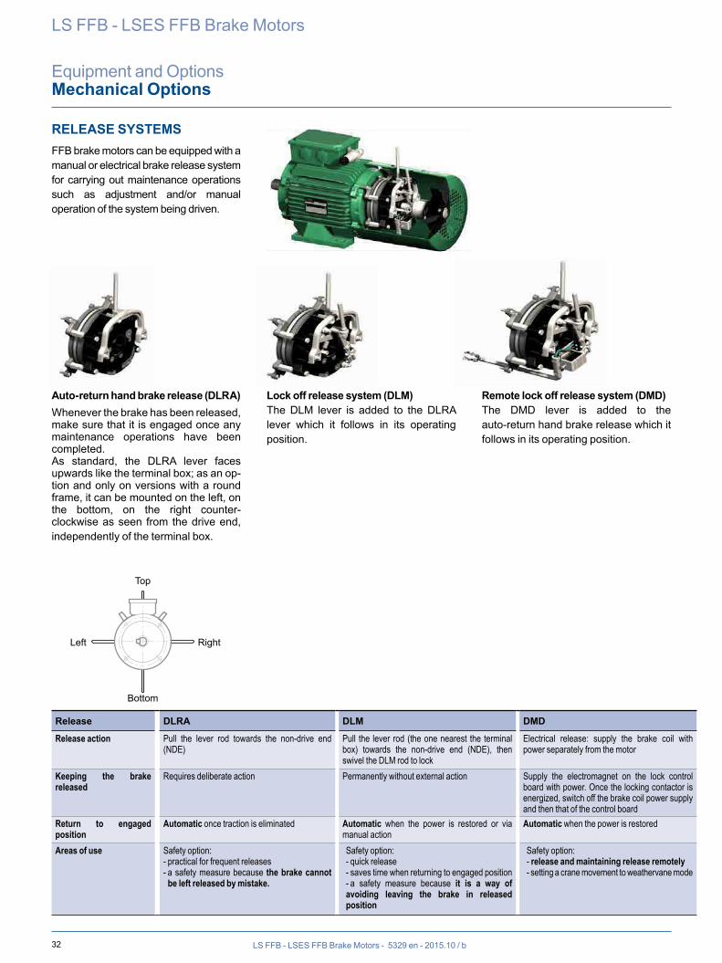
32 LS FFB - LSES FFB Brake Motors - 5329 en - 2015.10 / b
LS FFB - LSES FFB Brake Motors
Equipment and OptionsMechanical Options
RELEASE SYSTEMSFFB brake motors can be equipped with a manual or electrical brake release system for carrying out maintenance operations such as adjustment and/or manual operation of the system being driven.
Auto-return hand brake release (DLRA)Whenever the brake has been released, make sure that it is engaged once any maintenance operations have been completed.As standard, the DLRA lever faces upwards like the terminal box; as an op-tion and only on versions with a round frame, it can be mounted on the left, on the bottom, on the right counter-clockwise as seen from the drive end, independently of the terminal box.
Lock off release system (DLM)The DLM lever is added to the DLRA lever which it follows in its operating position.
Remote lock off release system (DMD)The DMD lever is added to the auto-return hand brake release which it follows in its operating position.
Release DLRA DLM DMD
Release action Pull the lever rod towards the non-drive end (NDE)
Pull the lever rod (the one nearest the terminal box) towards the non-drive end (NDE), then swivel the DLM rod to lock
Electrical release: supply the brake coil with power separately from the motor
Keeping the brake released
Requires deliberate action Permanently without external action Supply the electromagnet on the lock control board with power. Once the locking contactor is energized, switch off the brake coil power supply and then that of the control board
Return to engaged position
Automatic once traction is eliminated Automatic when the power is restored or via manual action
Automatic when the power is restored
Areas of use Safety option:- practical for frequent releases- a safety measure because the brake cannot be left released by mistake.
Safety option:- quick release- saves time when returning to engaged position- a safety measure because it is a way of avoiding leaving the brake in released position
Safety option:- release and maintaining release remotely- setting a crane movement to weathervane mode
Top
Bottom
RightLeft
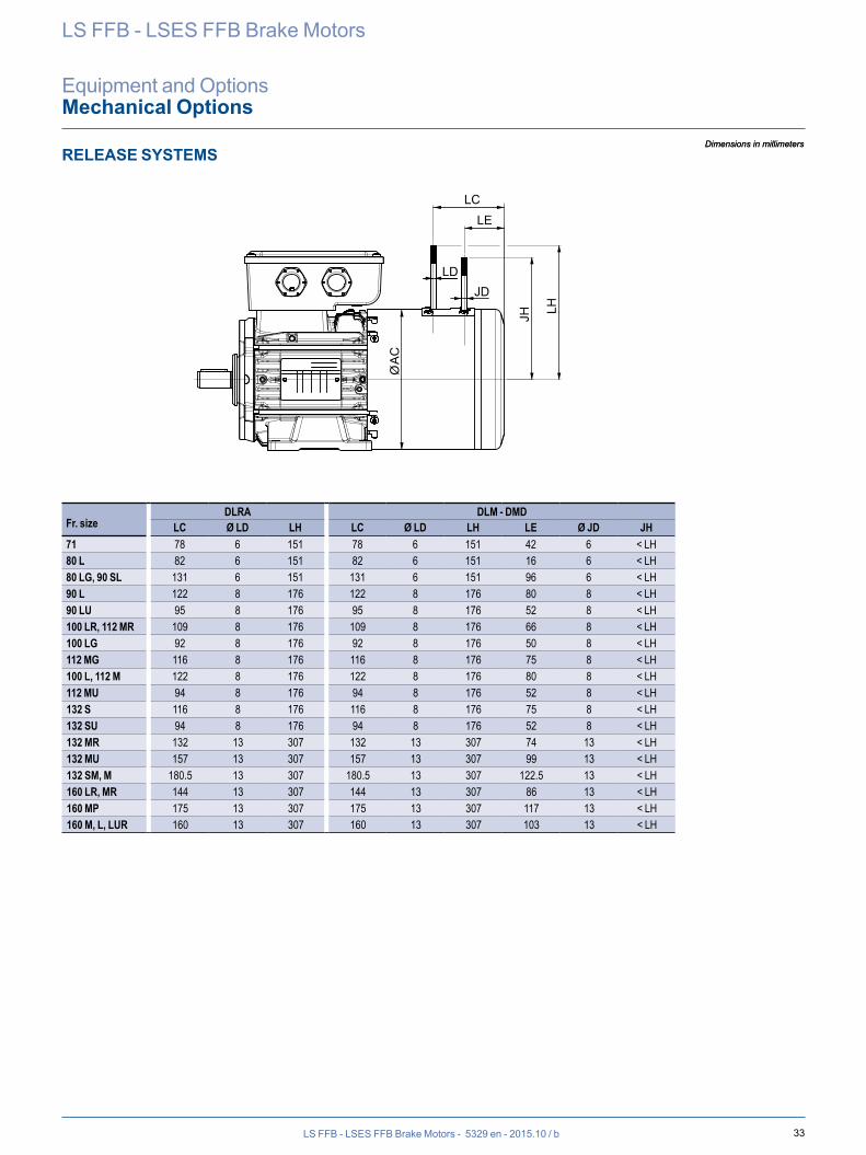
33LS FFB - LSES FFB Brake Motors - 5329 en - 2015.10 / b
Dimensions in millimeters
LS FFB - LSES FFB Brake Motors
Equipment and OptionsMechanical Options
RELEASE SYSTEMS
Fr. sizeDLRA DLM - DMD
LC Ø LD LH LC Ø LD LH LE Ø JD JH71 78 6 151 78 6 151 42 6 < LH80 L 82 6 151 82 6 151 16 6 < LH80 LG, 90 SL 131 6 151 131 6 151 96 6 < LH90 L 122 8 176 122 8 176 80 8 < LH90 LU 95 8 176 95 8 176 52 8 < LH100 LR, 112 MR 109 8 176 109 8 176 66 8 < LH100 LG 92 8 176 92 8 176 50 8 < LH112 MG 116 8 176 116 8 176 75 8 < LH100 L, 112 M 122 8 176 122 8 176 80 8 < LH112 MU 94 8 176 94 8 176 52 8 < LH132 S 116 8 176 116 8 176 75 8 < LH132 SU 94 8 176 94 8 176 52 8 < LH132 MR 132 13 307 132 13 307 74 13 < LH132 MU 157 13 307 157 13 307 99 13 < LH132 SM, M 180.5 13 307 180.5 13 307 122.5 13 < LH160 LR, MR 144 13 307 144 13 307 86 13 < LH160 MP 175 13 307 175 13 307 117 13 < LH160 M, L, LUR 160 13 307 160 13 307 103 13 < LH
Dimensions in millimeters
LCLE
LDJD
JH LH
ØA
C
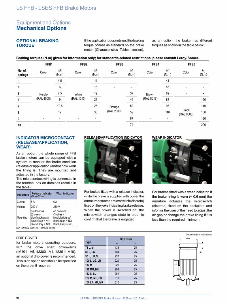
34 LS FFB - LSES FFB Brake Motors - 5329 en - 2015.10 / b
LS FFB - LSES FFB Brake Motors
Equipment and OptionsMechanical Options
OPTIONAL BRAKING TORQUE
If the application does not need the braking torque offered as standard on the brake motor (Characteristics Tables section),
as an option, the brake has different torques as shown in the table below.
Braking torques (N.m) given for information only; for standards-related restrictions, please consult Leroy-Somer.
FFB1 FFB2 FFB3 FFB4 FFB5
No. of springs Color Mf
(N.m) Color Mf(N.m) Color Mf
(N.m) Color Mf(N.m) Color Mf
(N.m)
3
Purple(RAL 4008)
4.5
White(RAL 1013)
11 - -
Brown(RAL 8017)
41 - -
4 6 15 - - 55 - -
5 7.5 19
Orange(RAL 2000)
37 69 - -
6 9 23 45 83
Black(RAL 9005)
120
7 10.5 26 52 96 140
8 12 30 59 110 160
9 - - - - 67 - - 180
10 - - - - 74 - - 200
INDICATOR MICROCONTACT (RELEASE/APPLICATION, WEAR)As an option, the whole range of FFB brake motors can be equipped with a system to monitor the brake condition (release or application) and/or how worn the lining is. They are mounted and adjusted in the factory.The microcontact wiring is connected in the terminal box on dominos (details in the table).
Indicators Release indicator(Open/Close)
Wear indicator
Current 6 A 6 AVoltage 250 V 250 V
Mounting
on dominos(3 wires - blue/black/gray)Black/Blue = NOBlack/Gray = NC
on dominos(3 wires - blue/black/gray)Black/Blue = NOBlack/Gray = NC
NO: normally open; NC: normally closed
RELEASE/APPLICATION INDICATOR
For brakes fitted with a release indicator, while the brake is supplied with power the armature actuates a microswitch (discrete) fixed on the yoke indicating brake release.When the power is switched off, the microswitch changes state in order to confirm that the brake is engaged.
WEAR INDICATOR
For brakes fitted with a wear indicator, if the brake lining is worn (+ 0.6 mm) the armature actuates the microswitch (discrete) fixed on the backplate and informs the user of the need to adjust the air gap or change the brake lining if it is less than the required minimum.
DRIP COVERfor brake motors operating outdoors, with the drive shaft downwards (IM1011 V5, IM3001 V1, IM3611 V18), an optional drip cover is recommended. This is an option and should be specified on the order if required.
TypeDrip cover
a b71 L, M 138 2580 L, LG 184 2590 L, LU, SL 220 25100 L, LG, LR 220 25112 M 220 25112 MG, MU 264 25132 S, SU 264 25132 M, MU, SM 310 25160 LR, MP, MR 310 25
Dimensions in millimeters
b
ø a
35LS FFB - LSES FFB Brake Motors - 5329 en - 2015.10 / b
LS FFB - LSES FFB Brake Motors
Equipment and OptionsElectrical Options
SENSORSMotors are protected by a manual or automatic overcurrent relay, placed between the isolating switch and the motor. This relay can in turn be protected by fuses. These protection devices provide total protection of the motor against non-transient overloads.
If a shorter reaction time is required, if you want to detect transient overloads, or if you wish to monitor temperature rises at “hot spots” in the motor or at strategic points in the installation for maintenance purposes, it is advisable to install heat sensors at sensitive points. The various types are shown in the table below, with a description of each.
We offer PTO, PTC, KTY and PT100 heat sensors. It must be emphasized that under no circumstances can these sensors be used to carry out direct regulation of the brake motor operating cycles.
Built-in indirect thermal protection
Type Operating principle Operating curve Breaking capacity (A) Protection provided Mounting
Number of devices*
Normally closed thermal protection
PTO
Bimetallic strip, indirectly heated, with normally closed (NC) contact
I
O TNFT
2.5 A at 250 Vwith cos j 0.4
general surveillancefor non-transient overloads
Mounted in control circuit
3 in series
Positive temperature coefficient thermistor
PTC
Non-linear variable resistor, indirectly heated
R
TTNF
0 general surveillancefor transient overloads
Mounted with associated relay in control circuit
3 in series
Temperature sensorKT U
Resistance depends on the winding temperature
R
T
0high accuracy continuous
surveillance of key hot spots
Mounted in control boards with associated reading equipment
(or recorder)
1 per hot spot
Platinum resistance thermometer
PT 100Linear variable resistor,
indirectly heated
R
T
0high accuracy continuous
surveillance of key hot spots
Mounted in control boards with associated reading equipment
(or recorder)
1 per hot spot
- NRT: nominal running temperature- The NRTs are chosen according to the position of the sensor in the motor and the temperature rise class.- PTC: as standard on frame size ≥160- KT U 84/130 as standard * The number of devices relates to the winding protection.
Fitting thermal protection- PTO or PTF, in the control circuits- PTC, with relay, in the control circuits- PT 100 or thermocouples, with reading equipment or recorder, in the installation control panel for continuous surveillance
Alarm and early warningAll protective equipment can be backed up by another type of protection (with different NRTs). The first device will then act as an early warning (light or sound signals given without shutting down the power circuits), and the second device will be an alarm (which shuts down the power circuits).
Built-in direct thermal protectionFor low rated currents, bimetallic strip-type protection can be used. The line current passes through the strip, which shuts down or restores the supply circuit as necessary. The design of this type of protection allows for manual or automatic reset.
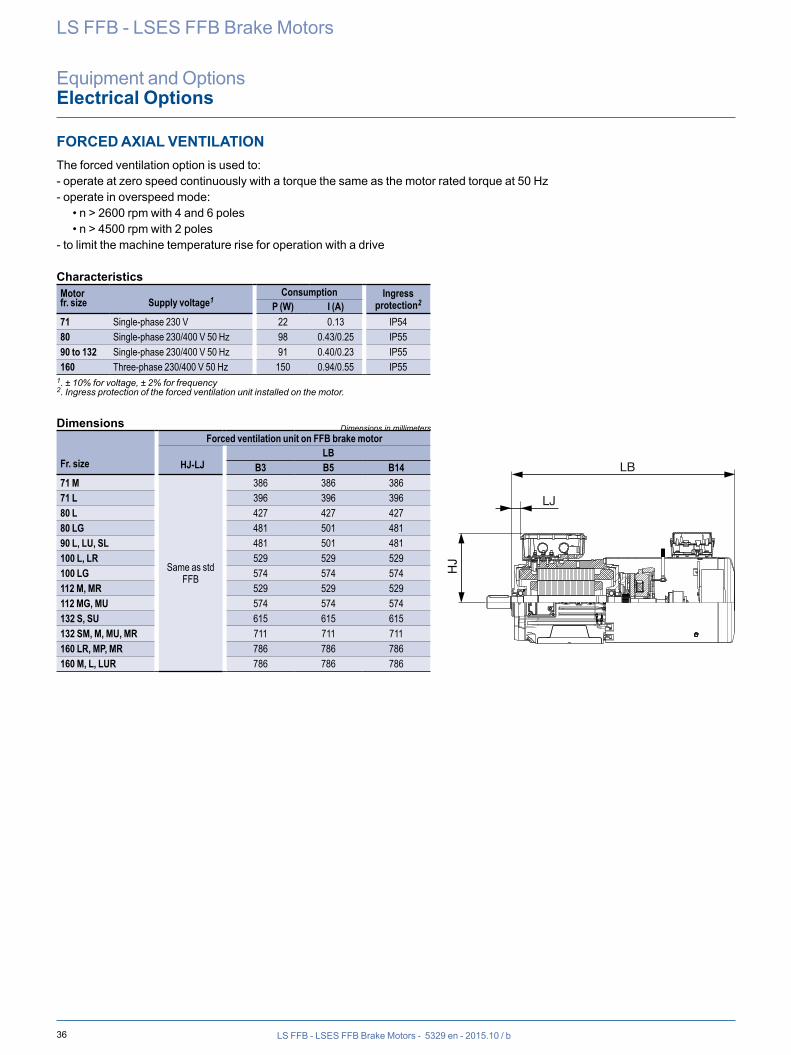
36 LS FFB - LSES FFB Brake Motors - 5329 en - 2015.10 / b
LS FFB - LSES FFB Brake Motors
Equipment and OptionsElectrical Options
FORCED AXIAL VENTILATIONThe forced ventilation option is used to:- operate at zero speed continuously with a torque the same as the motor rated torque at 50 Hz- operate in overspeed mode: • n > 2600 rpm with 4 and 6 poles • n > 4500 rpm with 2 poles- to limit the machine temperature rise for operation with a drive
CharacteristicsMotor fr. size Supply voltage1
Consumption Ingress protection2P (W) I (A)
71 Single-phase 230 V 22 0.13 IP5480 Single-phase 230/400 V 50 Hz 98 0.43/0.25 IP5590 to 132 Single-phase 230/400 V 50 Hz 91 0.40/0.23 IP55160 Three-phase 230/400 V 50 Hz 150 0.94/0.55 IP55
1. ± 10% for voltage, ± 2% for frequency2. Ingress protection of the forced ventilation unit installed on the motor.
Dimensions
Fr. size
Forced ventilation unit on FFB brake motor
HJ-LJLB
B3 B5 B1471 M
Same as std FFB
386 386 38671 L 396 396 39680 L 427 427 42780 LG 481 501 48190 L, LU, SL 481 501 481100 L, LR 529 529 529100 LG 574 574 574112 M, MR 529 529 529112 MG, MU 574 574 574132 S, SU 615 615 615132 SM, M, MU, MR 711 711 711160 LR, MP, MR 786 786 786160 M, L, LUR 786 786 786
Dimensions in millimeters
HJ
LB
LJ
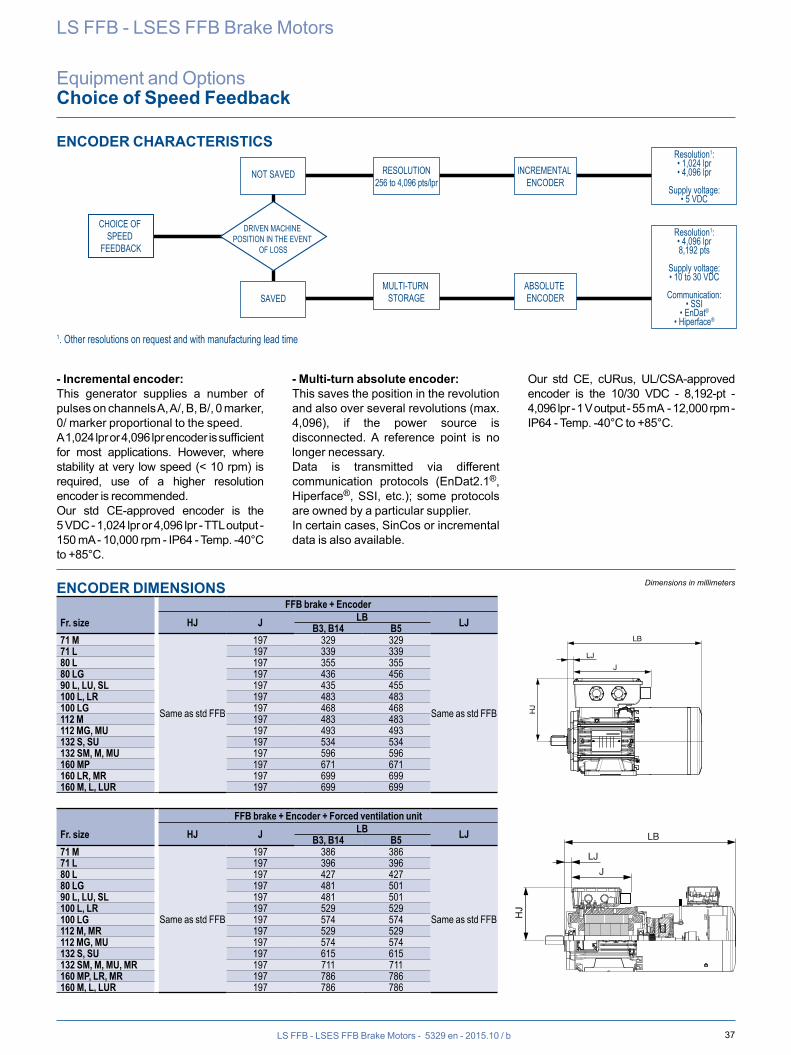
37LS FFB - LSES FFB Brake Motors - 5329 en - 2015.10 / b
LS FFB - LSES FFB Brake Motors
Equipment and OptionsChoice of Speed Feedback
ENCODER CHARACTERISTICS
NOT SAVED
SAVED
RESOLUTION256 to 4,096 pts/lpr
MULTI-TURN STORAGE
INCREMENTAL ENCODER
Resolution1:• 1,024 lpr• 4,096 lpr
Supply voltage:• 5 VDC
CHOICE OF SPEED
FEEDBACK
DRIVEN MACHINE POSITION IN THE EVENT
OF LOSS
ABSOLUTE ENCODER
1. Other resolutions on request and with manufacturing lead time
Resolution1:• 4,096 lpr8,192 pts
Supply voltage:• 10 to 30 VDC
Communication:• SSI
• EnDat®
• Hiperface®
- Incremental encoder:This generator supplies a number of pulses on channels A, A/, B, B/, 0 marker, 0/ marker proportional to the speed.A 1,024 lpr or 4,096 lpr encoder is sufficient for most applications. However, where stability at very low speed (< 10 rpm) is required, use of a higher resolution encoder is recommended.Our std CE-approved encoder is the 5 VDC - 1,024 lpr or 4,096 lpr - TTL output - 150 mA - 10,000 rpm - IP64 - Temp. -40°C to +85°C.
- Multi-turn absolute encoder:This saves the position in the revolution and also over several revolutions (max. 4,096), if the power source is disconnected. A reference point is no longer necessary.Data is transmitted via different communication protocols (EnDat2.1®, Hiperface®, SSI, etc.); some protocols are owned by a particular supplier.In certain cases, SinCos or incremental data is also available.
Our std CE, cURus, UL/CSA-approved encoder is the 10/30 VDC - 8,192-pt - 4,096 lpr - 1 V output - 55 mA - 12,000 rpm - IP64 - Temp. -40°C to +85°C.
ENCODER DIMENSIONS
Fr. sizeFFB brake + Encoder
HJ J LB LJB3, B14 B571 M
Same as std FFB
197 329 329
Same as std FFB
71 L 197 339 33980 L 197 355 35580 LG 197 436 45690 L, LU, SL 197 435 455100 L, LR 197 483 483100 LG 197 468 468112 M 197 483 483112 MG, MU 197 493 493132 S, SU 197 534 534132 SM, M, MU 197 596 596160 MP 197 671 671160 LR, MR 197 699 699160 M, L, LUR 197 699 699
Fr. sizeFFB brake + Encoder + Forced ventilation unit
HJ J LB LJB3, B14 B571 M
Same as std FFB
197 386 386
Same as std FFB
71 L 197 396 39680 L 197 427 42780 LG 197 481 50190 L, LU, SL 197 481 501100 L, LR 197 529 529100 LG 197 574 574112 M, MR 197 529 529112 MG, MU 197 574 574132 S, SU 197 615 615132 SM, M, MU, MR 197 711 711160 MP, LR, MR 197 786 786160 M, L, LUR 197 786 786
Dimensions in millimeters
HJ
LB
JLJ
HJ
LB
JLJ
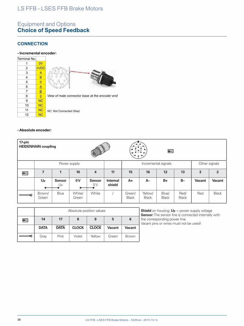
38 LS FFB - LSES FFB Brake Motors - 5329 en - 2015.10 / b
LS FFB - LSES FFB Brake Motors
Equipment and OptionsChoice of Speed Feedback
CONNECTION
- Incremental encoder:
- Absolute encoder:
Identification Process : POC 2 Classement / File : T10C003
CAHIER DES CHARGES CODEURS / ENCODER TECHNICAL SPECIFICATIONS
Révision : F
Date: 24/02/2014 Page : 3 / 9
DEPARTEMENT Annule et remplace / Cancels and replaces :
Q1T053 Révision E du/of 07/05/2013 Doc type : S6T002 Rev A du/of 12/12/2011 M R I
1.2.2 Connectique LEROY-SOMER
Vue sur l'embase connecteur mâle coté codeur
* NC = Non Connecté(libre)
Blindage / carter connecteur
1.2.3 Raccordement des masses
La connexion de masse dans les connecteurs doit respecter les règles de la CEM via une reprise de masse à 360°C au niveau du presse-étoupe sur le corps du codeur et dans le PE du connecteur.
1.2.4 Étiquettes signalétiques
Il doit y avoir 2 étiquettes de même matière comportant au moins le n° de série, type, tension, nombre de points:
- Une étiquette sur le corps du produit- Une étiquette en drapeau sur le câble du codeur à 50mm du connecteur
(Texte lisible facilement)
N° borne
1 0V 2 +VCC3 A 4 B 5 0 6 A 7 B 8 0 9 NC
10 NC 11 NC 12 NC
Terminal No.1 0V2 +VDC3 A4 B5 06 A7 B8 09 NC
10 NC11 NC12 NC
View of male connector base at the encoder end
NC: Not Connected (free)
����������������������������������������������������������� ���� ���������������� ������������� �������� �����������������������������
����������������
Pin layout17-pinHEIDENHAIN coupling
Power supply Incremental signals Other signals
7 1 10 4 11 15 16 12 13 3 2
UP SensorUP
0 V Sensor0 V
Internal shield
A+ A– B+ B– Vacant Vacant
Brown/Green
Blue White/Green
White / Green/Black
Yellow/Black
Blue/Black
Red/Black
Red Black
Absolute position values Shield on housing; UP = power supply voltageSensor: The sensor line is connected internally with the corresponding power line.Vacant pins or wires must not be used!
14 17 8 9 5 6
DATA DATA CLOCK CLOCK Vacant Vacant
Gray Pink Violet Yellow Green Brown
Fore more Information seeCatalog Rotary encoders•
Electrical Connection
519 974 · 01 · A · 22 · pdf · 7/2008 · Subject to change without notice
��������������������������� �������������������� � ��������������� ����������� ������������������������������������
�����������������
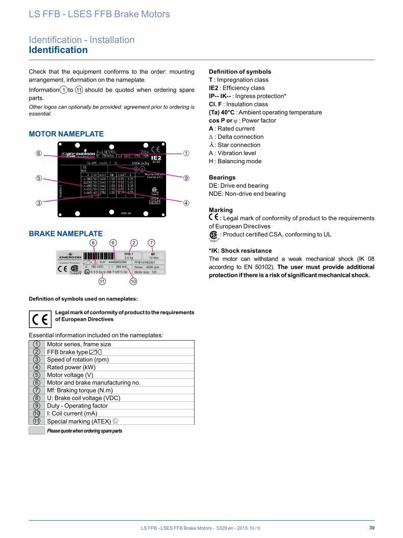
39LS FFB - LSES FFB Brake Motors - 5329 en - 2015.10 / b
LS FFB - LSES FFB Brake Motors
Identification - InstallationIdentification
Check that the equipment conforms to the order: mounting arrangement, information on the nameplate.Information 1 to 11 should be quoted when ordering spare parts.Other logos can optionally be provided: agreement prior to ordering is essential.
MOTOR NAMEPLATE
BRAKE NAMEPLATE
FFB141NU001
Mf : 12 Nm
S N° : 4446893/000 U : 180 VDC I : 295 mA
Motor size : 125 Nmax : 4500 rpm
II 3 D Ex tc IIIB T125°C Dc
FFB 1 2.4 kg
26 78
11 10
Definition of symbols used on nameplates:
Legal mark of conformity of product to the requirements of European Directives
Essential information included on the nameplates:1 Motor series, frame size2 FFB brake type 3 Speed of rotation (rpm) 4 Rated power (kW) 5 Motor voltage (V) 6 Motor and brake manufacturing no.7 Mf: Braking torque (N.m)8 U: Brake coil voltage (VDC) 9 Duty - Operating factor
10 I: Coil current (mA)11 Special marking (ATEX)
Please quote when ordering spare parts
Definition of symbolsT : Impregnation class IE2 : Efficiency class IP-- IK-- : Ingress protection*Cl. F : Insulation class(Ta) 40°C : Ambient operating temperaturecos P or j : Power factorA : Rated current∆ : Delta connectionY
: Star connectionA : Vibration levelH : Balancing mode
BearingsDE: Drive end bearingNDE: Non-drive end bearing
Marking : Legal mark of conformity of product to the requirements
of European Directives
C US166631
® : Product certified CSA, conforming to UL
*IK: Shock resistanceThe motor can withstand a weak mechanical shock (IK 08 according to EN 50102). The user must provide additional protection if there is a risk of significant mechanical shock.
➅ ➀
➄ ➈
➂ ➃
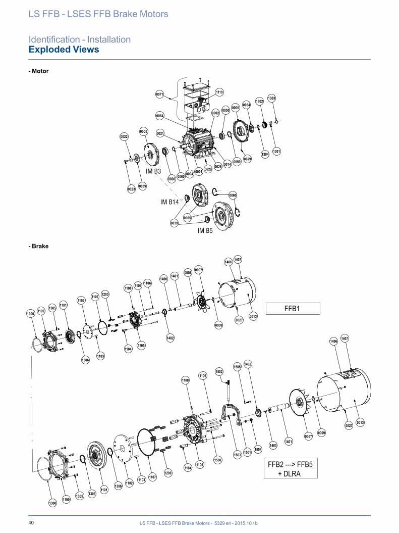
40 LS FFB - LSES FFB Brake Motors - 5329 en - 2015.10 / b
LS FFB - LSES FFB Brake Motors
Identification - InstallationExploded Views
- Motor
1300
13031302
005400060050
0002
11100071
0084
00210022
0005
00230039
00390005
0030 0060
0060
0004 0001 0629 0026 0014 00590629
13041301
13001100
1305 13061101
13061102
1103 11071200
11041105
15001503 1501
15041400
14010007
0009
00270013
14071406
14021505
15021106
1108
13051101
11021107 1200
1108 1109 11061400
14010008
0007
1406 1407
00130027
0009
1402
11051104
11031306
1100 FFB1
FFB2 ---> FFB5 + DLRA
IM B14
IM B3
IM B5
- Brake
1300
13031302
0054000600500002
11100071
0084
00210022
0005
00230039
00390005
0030 0060
0060
0004 0001 0629 0026 0014 0059 06291304
1301
13001100
1305 13061101
13061102
1103 11071200
11041105
15001503 1501
15041400
14010007
0009
00270013
14071406
140215051502
11061108
13051101
11021107 1200
1108 1109 11061400
14010008 0007
1406 1407
00130027
0009
1402
11051104
11031306
1100 FFB1
FFB2 ---> FFB5 + DLRA
IM B14
IM B3
IM B5
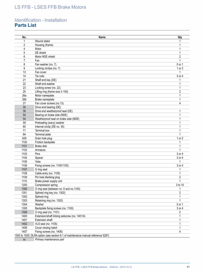
41LS FFB - LSES FFB Brake Motors - 5329 en - 2015.10 / b
LS FFB - LSES FFB Brake Motors
Identification - InstallationParts List
No. Name Qty1 Wound stator 12 Housing (frame) 14 Rotor 15 DE shield 16 Motor NDE shield 27 Fan 18 Fan washer (no. 7) 0 or 19 Locking circlips (no. 7) 1 or 2
13 Fan cover 114 Tie rods 3 or 421 Shaft end key (DE) 122 Shaft end washer 123 Locking screw (no. 22) 125 Lifting ring (frame size ≥ 100) 2
26a Motor nameplate 126b Brake nameplate 127 Fan cover screws (no.13) 430 Drive end bearing (DE)39 Drive end weatherproof seal (DE) 150 Bearing on brake side (NDE) 154 Weatherproof seal on brake side (NDE) 159 Preloading (wavy) washer 160 Internal circlip (DE no. 30) 171 Terminal box 184 Terminal plate 1
629 Drain hole plug 1 or 21100 Friction backplate 11101 Brake disk 11102 Armature 11103 Pins 3 or 41104 Spacer 3 or 41105 Yoke 11106 Fixing screws (no. 1105/1100) 3 or 41107 O ring seal 11108 Cable entry (no. 1105) 11109 Pin hole blanking plug 21110 Brake power supply unit 11200 Compression spring 3 to 101300 O ring seal (between no. 6 and no.1100) 11301 Splined ring key (no. 1302) 21302 Splined ring 11303 Retaining ring (no. 1302) 11304 Washer 0 or 11305 Backplate fixing screws (no. 1100) 3 or 41306 O ring seal (no. 1101) 21400 Extension/shaft linking setscrew (no. 1401/4) 11401 Extension shaft 11402 VLS seal (no. 1105) 11406 Cover closing hatch 11407 Fixing screws (no. 1406) 4
1500 to 1505: DLRA option (see section 6.1 of maintenance manual reference 5287)xx Primary maintenance part
42 LS FFB - LSES FFB Brake Motors - 5329 en - 2015.10 / b
LS FFB - LSES FFB Brake Motors
Identification - InstallationInstallation
The following information is given for guidance only, and should never be used as a substitute for the current standards, nor does it relieve the installation company of its responsibility.Depending on the installation, more optional elements can be added to the installation:
RECEIPTCheck the state of the brake motor; if there is any damage to the motor or even its packaging, contact the carrier.Check that the brake motor conforms to the order (mounting arrangement, information on the nameplates).
STORAGEStore the equipment in a clean, dry location, protected from shocks, vibrations, variations in temperature and in an environment with relative humidity of less than 90%.Storage for longer than 6 months leads to special conditions, we will be happy to discuss these with you.After storage for a period of more than 6 months, disconnect the brake power supply unit and check the winding insulation resistance (phase/earth resistance higher than 10 MΩ).Drain any condensation water.
COMMISSIONINGThe brake motor is designed to operate at the speeds indicated on the nameplate (do not exceed the maximum speed stated on the brake nameplate: Nmax).Comply with the voltages and frequencies indicated on the nameplate.(Do not deviate by more than 5% from the voltage extremes on the nameplate and by more than 1% from the frequencies).For hoisting applications, do not use a motor that is not rated S3 (except for variable speed). Do not use a motor with a different duty type from that on the nameplate no. ⑨ (see Motor Nameplate section on page 39).
MECHANICAL INSTALLATIONSee manuals ref. 5286 (FFB brake motor installation manual) and ref. 1889 (Recommendations for storing and commissioning AC motors manual).If the brake motor has been stored at a temperature lower than -10°C, heat it and turn the shaft manually before starting up the machine.If the brake motor is to be used at a temperature lower than -25°C, it must not be fitted with a sensor. It can be fitted with thermocouples.Ensure there is minimum clearance (corresponding to the length of the cover) at the non-drive end of the brake motor so it can be put down (inspections and brake adjustment).Install the brake motor in conditions conforming to those on the order (temperature, relative humidity, altitude).When the brake motor is fitted with lifting rings, these are for lifting the brake motor on its own.Mount the brake motor in the position specified on the order, on a flat, rigid base in order to prevent distortion and vibration.Ensure the fixing screws are tightened to the correct tightening torque (class 8.8 minimum according to ISO 898-1), the screw diameter must be the right size for the fixing holes.Ensure the mechanical shafts are aligned and the coupling and pulley are mounted in accordance with good practice.Do not knock the motor (terminal box, cover), the shaft or the coupling during mounting, do not crush the seal, do not project beyond the shoulder of the shaft.Ensure correct brake motor cooling, the air intakes and outlets must be kept clear.Check that the loads applied to the motor shaft (especially the belt tension) are compatible with the values stated in our technical catalogues.
WIRINGDrive power supply cablesThese cables do not necessarily need shielding. Their cross-section is recommended in the drive documentation, however, it can be adapted according to the type of cable, installation method, the cable length (voltage drop), etc. See the Sizing power cables section below.
Motor power supply cablesThese cables must be shielded to ensure EMC conformance of the installation. The cable shielding must be connected over 360° at both ends. At the motor end, special EMC cable glands are available as an option. The cable cross-section is recommended in the motor documentation, however, it can be adapted according to the type of cable, installation method, the cable length (voltage drop), etc. See the Sizing power cables section below.
Encoder cablesShielding the sensor cables is important due to the high voltages and currents present at the drive output. This cable must be laid at least 30 cm away from any power cables. See the Encoders section.
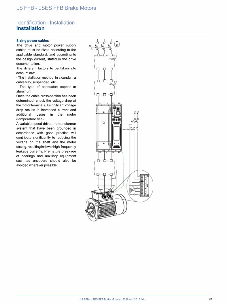
43LS FFB - LSES FFB Brake Motors - 5329 en - 2015.10 / b
LS FFB - LSES FFB Brake Motors
Identification - InstallationInstallation
Sizing power cablesThe drive and motor power supply cables must be sized according to the applicable standard, and according to the design current, stated in the drive documentation.The different factors to be taken into account are:- The installation method: in a conduit, a cable tray, suspended, etc.- The type of conductor: copper or aluminumOnce the cable cross-section has been determined, check the voltage drop at the motor terminals. A significant voltage drop results in increased current and additional losses in the motor (temperature rise).A variable speed drive and transformer system that have been grounded in accordance with good practice will contribute significantly to reducing the voltage on the shaft and the motor casing, resulting in fewer high-frequency leakage currents. Premature breakage of bearings and auxiliary equipment such as encoders should also be avoided wherever possible.
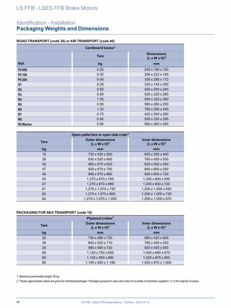
44 LS FFB - LSES FFB Brake Motors - 5329 en - 2015.10 / b
LS FFB - LSES FFB Brake Motors
Identification - InstallationPackaging Weights and Dimensions
ROAD TRANSPORT (code 30) or AIR TRANSPORT (code 40)
Cardboard boxes1
Ref.
Tare Dimensions(L x W x H)2
kg mm
P0 000 0.25 245 x 190 x 150P0 100 0.35 256 x 222 x 165P0 200 0.40 330 x 288 x 172R1 0.25 330 x 145 x 200R2 0.50 420 x 200 x 240R3 0.65 520 x 220 x 280R4 1.05 550 x 320 x 360R5 0.85 580 x 260 x 280R6 1.30 780 x 300 x 430R7 0.75 420 x 300 x 260R8 0.90 500 x 330 x 290R5 Marine 0.85 580 x 260 x 280
Open pallet box or open-slat crate1
Tare Outer dimensions(L x W x H)2
Inner dimensions(L x W x H)2
kg mm mm10 720 x 420 x 550 650 x 350 x 40026 830 x 520 x 660 760 x 450 x 50030 990 x 570 x 620 920 x 500 x 55047 920 x 870 x 700 850 x 800 x 55048 990 x 870 x 880 920 x 800 x 72045 1,270 x 870 x 700 1,200 x 800 x 55047 1,270 x 870 x 880 1,200 x 800 x 72061 1,270 x 1,070 x 730 1,200 x 1,000 x 55062 1,270 x 1,070 x 900 1,200 x 1,000 x 72064 1,270 x 1,070 x 1,050 1,200 x 1,000 x 870
PACKAGING FOR SEA TRANSPORT (code 10)Plywood crates1
Tare Outer dimensions(L x W x H)2
Inner dimensions(L x W x H)2
kg mm mm20 740 x 480 x 730 680 x 420 x 60026 840 x 520 x 710 760 x 440 x 53030 980 x 560 x 720 920 x 500 x 55058 1,120 x 750 x 850 1,040 x 680 x 67060 1,100 x 950 x 680 1,020 x 870 x 50080 1,100 x 950 x 1,180 1,020 x 870 x 1,000
1. Maximum permissible weight: 50 kg2. Theses approximate values are given for individual packages. Packages grouped in open slat crates for quantity of machines supplied > 5, in the majority of cases.
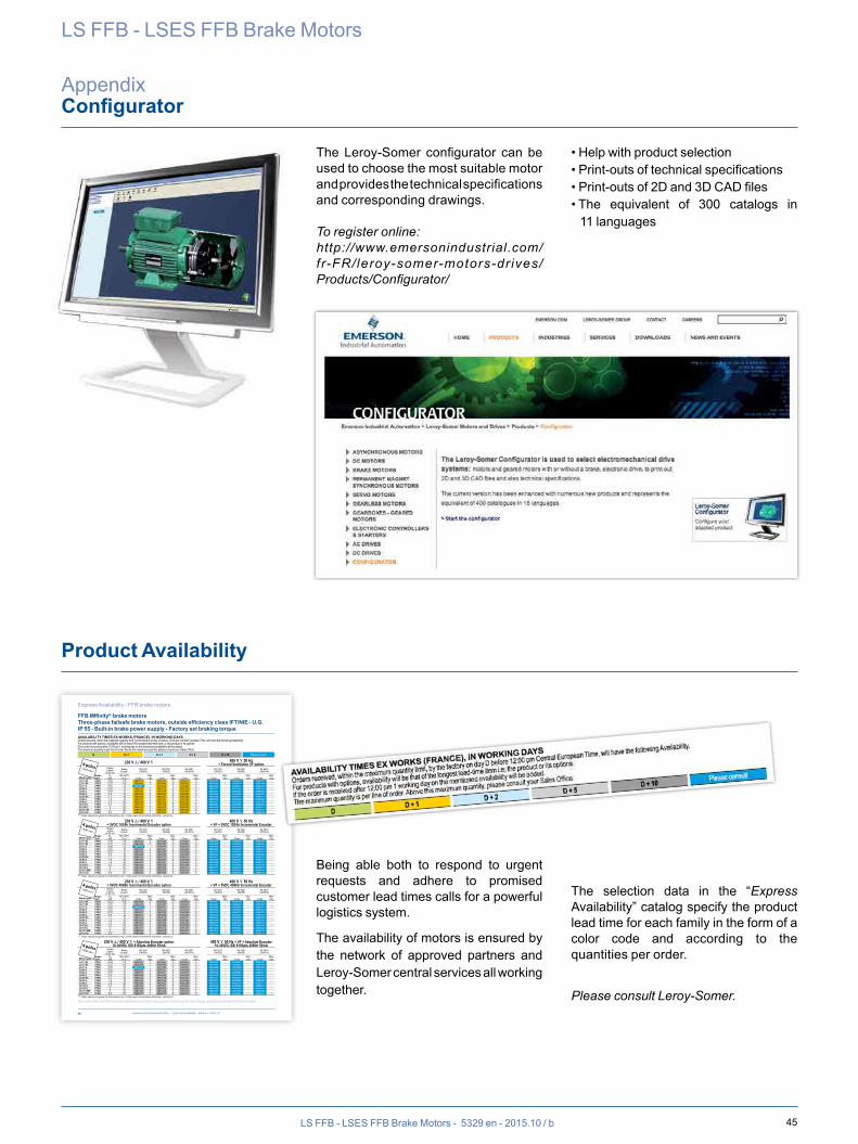
45LS FFB - LSES FFB Brake Motors - 5329 en - 2015.10 / b
66
Your sales office will offer every assistance and consider any enquiry concerning delivery of larger quantities and different delivery dates
Emerson Industrial Automation - Express Availability - 4904 en - 2015.10
AVAILABILITY TIMES EX WORKS (FRANCE), IN WORKING DAYSOrders received, within the maximum quantity limit, by the factory on day D before 12:00 pm Central European Time, will have the following Availability.For products with options, availability will be that of the longest lead-time item i.e; the product or its options. If the order is received after 12:00 pm 1 working day on the mentioned availability will be added.The maximum quantity is per line of order. Above this maximum quantity, please consult your Sales Office.
D D + 1 D + 2 D + 5 D + 10 Please consult
Express Availability - FFB brake motors
FFB IMfinity® brake motorsThree-phase failsafe brake motors, outside efficiency class IFT/NIE - U.G.IP 55 - Built-in brake power supply - Factory set braking torque
230 V Δ / 400 V Υ 400 V Υ 50 Hz+ Forced Ventilation VF option
Rated power
at 50 HzBrake
torque1IM 1001(IM B3)
IM 3001(IM B5)
IM 3601(IM B14)
IM 1001(IM B3)
IM 3001(IM B5)
IM 3601(IM B14)
Motor typeBraketype
PNkW
Mf ±20%N.m Code
Max.Qty Code
Max.Qty Code
Max.Qty Code
Max.Qty Code
Max.Qty Code
Max.Qty
LS 71 M FFB1 0.25 4.5 4969419 2 4969420 5 4969421 5 4969422 - 4969423 - 4969424 -LS 71 M FFB1 0.37 4.5 4969443 2 4969444 5 4969445 5 4969446 - 4969447 - 4969448 -LS 71 L FFB1 0.55 12 4969467 - 4969468 5 4969469 5 4969470 - 4969471 - 4969472 -LS 80 L FFB1 0.55 12 4965234 2 4965235 5 4965236 5 4965237 - 4965238 - 4965239 -LS 80 L FFB1 0.75 12 4965258 2 4965259 5 4965260 5 4965261 - 4965262 - 4965263 -LS 80 L FFB1 0.9 12 4965282 2 4965283 5 4965284 5 4965285 - 4965286 - 4965287 -LS 90 SL FFB2 1.1 19 4965306 2 4965307 5 4965308 5 4965309 - 4965310 - 4965311 -LS 90 L FFB2 1.5 19 4965330 2 4965331 5 4965332 5 4965333 - 4965334 - 4965335 -LS 90 L FFB2 1.8 26 4965354 2 4965355 5 4965356 5 4965357 - 4965358 - 4965359 -LS 100 L FFB2 2.2 26 4965378 2 4965379 5 4965380 5 4965381 - 4965382 - 4965383 -LS 100 L FFB3 3 52 4965402 2 4965403 5 4965404 5 4965405 - 4965406 - 4965407 -LS 112 M FFB3 4 52 4965426 2 4965427 5 4965428 5 4965429 - 4965430 - 4965431 -LS 132 S FFB3 5.5 67 4965450 2 4969300 5 4969301 5 4969302 - 4969303 - 4969304 -
(1) These values are given for information only ; in the event of normative restriction, consult us
230 V Δ / 400 V Υ+ 5VDC 1024tr Incremental Encoder option
400 V Υ 50 Hz+ VF + 5VDC 1024tr Incremental Encoder
Rated power
at 50 HzBrake
torque1IM 1001(IM B3)
IM 3001(IM B5)
IM 3601(IM B14)
IM 1001(IM B3)
IM 3001(IM B5)
IM 3601(IM B14)
Motor typeBraketype
PNkW
Mf ±20%N.m Code
Max.Qty Code
Max.Qty Code
Max.Qty Code
Max.Qty Code
Max.Qty Code
Max.Qty
LS 71 M FFB1 0.25 4.5 4969425 2 4969426 5 4969427 5 4969434 - 4969435 - 4969436 -LS 71 M FFB1 0.37 4.5 4969449 2 4969450 5 4969451 5 4969458 - 4969459 - 4969460 -LS 71 L FFB1 0.55 12 4969473 - 4969474 5 4969475 5 4969482 - 4969483 - 4969484 -LS 80 L FFB1 0.55 12 4965240 2 4965241 5 4965242 5 4965249 - 4965250 - 4965251 -LS 80 L FFB1 0.75 12 4965264 2 4965265 5 4965266 5 4965273 - 4965274 - 4965275 -LS 80 L FFB1 0.9 12 4965288 2 4965289 5 4965290 5 4965297 - 4965298 - 4965299 -LS 90 SL FFB2 1.1 19 4965312 2 4965313 5 4965314 5 4965321 - 4965322 - 4965323 -LS 90 L FFB2 1.5 19 4965336 2 4965337 5 4965338 5 4965345 - 4965346 - 4965347 -LS 90 L FFB2 1.8 26 4965360 2 4965361 5 4965362 5 4965369 - 4965370 - 4965371 -LS 100 L FFB2 2.2 26 4965384 2 4965385 5 4965386 5 4965393 - 4965394 - 4965395 -LS 100 L FFB3 3 52 4965408 2 4965409 5 4965410 5 4965417 - 4965418 - 4965419 -LS 112 MR FFB3 4 52 4965432 2 4965433 5 4965434 5 4965441 - 4965442 - 4965443 -LS 132 S FFB3 5.5 67 4969305 2 4969306 5 4969307 5 4969314 - 4969315 - 4969316 -
(1) These values are given for information only ; in the event of normative restriction, consult us
4 poles1500 min -1
4 poles1500 min -1
230 V Δ / 400 V Υ+ 5VDC 4096tr Incremental Encoder option
400 V Υ 50 Hz+ VF + 5VDC 4096tr Incremental Encoder
Rated power
at 50 HzBrake
torque1IM 1001(IM B3)
IM 3001(IM B5)
IM 3601(IM B14)
IM 1001(IM B3)
IM 3001(IM B5)
IM 3601(IM B14)
Motor typeBraketype
PNkW
Mf ±20%N.m Code
Max.Qty Code
Max.Qty Code
Max.Qty Code
Max.Qty Code
Max.Qty Code
Max.Qty
LS 71 M FFB1 0.25 4.5 4969428 2 4969426 5 4969430 5 4969437 - 4969438 - 4969439 -LS 71 M FFB1 0.37 4.5 4969452 2 4969453 5 4969454 5 4969461 - 4969462 - 4969463 -LS 71 L FFB1 0.55 12 4969476 - 4969477 5 4969478 5 4969485 - 4969486 - 4969487 -LS 80 L FFB1 0.55 12 4965243 2 4965244 5 4965245 5 4965252 - 4965253 - 4965254 -LS 80 L FFB1 0.75 12 4965267 2 4965268 5 4965269 5 4965276 - 4965277 - 4965278 -LS 80 L FFB1 0.9 12 4965291 2 4965292 5 4965293 5 4965300 - 4965301 - 4965302 -LS 90 SL FFB2 1.1 19 4965315 2 4965316 5 4965317 5 4965324 - 4965325 - 4965326 -LS 90 L FFB2 1.5 19 4965339 2 4965340 5 4965341 5 4965348 - 4965349 - 4965350 -LS 90 L FFB2 1.8 26 4965363 2 4965364 5 4965365 5 4965372 - 4965373 - 4965374 -LS 100 L FFB2 2.2 26 4965387 2 4965388 5 4965389 5 4965396 - 4965397 - 4965398 -LS 100 L FFB3 3 52 4965411 2 4965412 5 4965413 5 4965420 - 4965421 - 4965422 -LS 112 MR FFB3 4 52 4965435 2 4965436 5 4965437 5 4965444 - 4965445 - 4965446 -LS 132 S FFB3 5.5 67 4969308 2 4969309 5 4969310 5 4969317 - 4969318 - 4969319 -
(1) These values are given for information only ; in the event of normative restriction, consult us
230 V Δ / 400 V Υ + Absolute Encoder option10-30VDC SSI 8192pts 4096tr 55mA
400 V Υ 50 Hz + VF + Absolute Encoder10-30VDC SSI 8192pts 4096tr 55mA
Rated power
at 50 HzBrake
torque1IM 1001(IM B3)
IM 3001(IM B5)
IM 3601(IM B14)
IM 1001(IM B3)
IM 3001(IM B5)
IM 3601(IM B14)
Motor typeBraketype
PNkW
Mf ±20%N.m Code
Max.Qty Code
Max.Qty Code
Max.Qty Code
Max.Qty Code
Max.Qty Code
Max.Qty
LS 71 M FFB1 0.25 4.5 4969431 2 4969432 5 4969433 5 4969440 - 4969441 - 4969442 -LS 71 M FFB1 0.37 4.5 4969455 2 4969456 5 4969457 5 4969464 - 4969465 - 4969466 -LS 71 L FFB1 0.55 12 4969479 - 4969480 5 4969481 5 4969488 - 4969489 - 4969490 -LS 80 L FFB1 0.55 12 4965246 2 4965247 5 4965248 5 4965255 - 4965256 - 4965257 -LS 80 L FFB1 0.75 12 4965270 2 4965271 5 4965272 5 4965279 - 4965280 - 4965281 -LS 80 L FFB1 0.9 12 4965294 2 4965295 5 4965296 5 4965303 - 4965304 - 4965305 -LS 90 SL FFB2 1.1 19 4965318 2 4965319 5 4965320 5 4965327 - 4965328 - 4965329 -LS 90 L FFB2 1.5 19 4965342 2 4965343 5 4965344 5 4965351 - 4965352 - 4965353 -LS 90 L FFB2 1.8 26 4965366 2 4965367 5 4965368 5 4965375 - 4965376 - 4965377 -LS 100 L FFB2 2.2 26 4965390 2 4965391 5 4965392 5 4965399 - 4965400 - 4965401 -LS 100 L FFB3 3 52 4965414 2 4965415 5 4965416 5 4965423 - 4965424 - 4965425 -LS 112 MR FFB3 4 52 4965438 2 4965439 5 4965440 5 4965447 - 4965448 - 4965449 -LS 132 S FFB3 5.5 67 4969311 2 4969312 5 4969313 5 4969320 - 4969321 - 4969322 -
(1) These values are given for information only ; in the event of normative restriction, consult us
4 poles1500 min -1
4 poles1500 min -1
Configurator
Being able both to respond to urgent requests and adhere to promised customer lead times calls for a powerful logistics system.
The availability of motors is ensured by the network of approved partners and Leroy-Somer central services all working together.
The selection data in the “Express Availability” catalog specify the product lead time for each family in the form of a color code and according to the quantities per order.
Please consult Leroy-Somer.
The Leroy-Somer configurator can be used to choose the most suitable motor and provides the technical specifications and corresponding drawings.
To register online:http://www.emersonindustrial.com/fr-FR/leroy-somer-motors-dr ives/Products/Configurator/
• Help with product selection• Print-outs of technical specifications• Print-outs of 2D and 3D CAD files• The equivalent of 300 catalogs in
11 languages
Product Availability
LS FFB - LSES FFB Brake Motors
Appendix

46 LS FFB - LSES FFB Brake Motors - 5329 en - 2015.10 / b
Notes

47LS FFB - LSES FFB Brake Motors - 5329 en - 2015.10 / b
Notes
© Emerson 2014. The information in this brochure is provided for guidance only and is no way contractual. Emerson's continuous development policy means its accuracy cannot be guaranteed. Emerson reserves the right to modify the characteristics of its products without notice.
Control Techniques Limited. Registered office: The Gro, Newtown, Powys SY16 3BE. Company registered in England and Wales. Company registration no: 01236886.
Moteurs Leroy-Somer SAS. Registered office: Bd Marcellin Leroy, CS 10015, 16915 Angoulême Cedex 9, France. Registered capital: €65,800,512, RCS Angoulême 338 567 258.
www.emersonindustrial.com/automation
5329 en - 2015.10 / b