Embed Size (px)
Citation preview

Taking Shelter from the StormBuilding a Safe Room for Your Home or Small Business
Includes Construction Plans
FEMA P-320, Fourth Edition / December 2014

Taking Shelter from the Storm
Building a Safe Room for Your Home or Small Business
Includes Construction Plans
FEMA P-320, Fourth Edition / December 2014

Any opinions, findings, conclusions, or recommendations expressed in this publication do not necessarily reflect the views of FEMA. Additionally, neither FEMA nor any of its employees makes any warrantee, expressed or implied, or assumes any legal liability or responsibility for the accuracy, completeness, or usefulness of any information, product, or process included in this publication.
Users of information contained in this publication assume all liability arising from such use.

T A K I N G S H E L T E R F R O M T H E S T O R M i Building a Safe Room for Your Home or Small Business
PREFACE
The Federal Emergency Management Agency (FEMA) is pleased to have this opportunity to update and improve the guidance through this new edition of FEMA P-320, Taking Shelter from the Storm: Building a Safe Room for Your Home or Small Business. Since the first edition of FEMA P-320 was issued in 1998, more than 1 million copies of the publication have been distributed, and nearly 25,000 residential safe rooms have been constructed with FEMA funding assistance.
Other positive developments include but are not limited to:
• The construction of tens of thousands of safe rooms with private funds.
• The International Code Council’s (ICC’s) release of a consensus standard on the design and construction of storm shelters. This standard, the ICC/NSSA Standard for the Design and Construction of Storm Shelters (ICC 500) is a referenced standard in the 2009, 2012, and 2015 International Building Code and International Residential Code.

T A K I N G S H E L T E R F R O M T H E S T O R M iii Building a Safe Room for Your Home or Small Business
CONTENTS Preface .................................................................................................................................................................... i
Acronyms ................................................................................................................................................................. vii
Chapter 1.. Introduction ............................................................................................................................................. 1
Chapter 2. Understanding the Hazards .................................................................................................................... 5
2.1 Tornadoes ........................................................................................................................................ 5
2.2 Hurricanes ....................................................................................................................................... 8
2.3 Effects of Extreme Winds on a Building ......................................................................................10
2.4 Do You Need a Safe Room? ...........................................................................................................11
2.5 Assessing Your Risk ........................................................................................................................13
Chapter 3. Planning Your Safe Room ..................................................................................................................... 15
3.1 Design Basis ................................................................................................................................... 15
3.2 Flood Hazard Siting and Elevation ...............................................................................................163.2.1 Flood Hazard Siting Criteria .............................................................................................163.2.2 Flood Hazard Elevation Criteria .......................................................................................17
3.3 New versus Existing Homes or Buildings .....................................................................................17
3.4 Safe Room Size ...............................................................................................................................19
3.5 Safe Room Locations .................................................................................................................... 203.5.1 Siting Your Safe Room: Inside or Outside? ..................................................................... 203.5.2 Siting a Safe Room Inside a Home or Small Business .....................................................21
3.6 Floor Plans Showing Possible Safe Room Locations .................................................................. 233.6.1 Floor Plan 1: Basement ..................................................................................................... 233.6.2 Floor Plan 2: Safe Rooms on the Primary Level of a Home or Small Business ............ 233.6.3 Floor Plan 3: In-Ground Safe Rooms .............................................................................. 233.6.4 Floor Plan 4: Multipurpose Safe Rooms in a Small Business .........................................243.6.5 Selection of Safe Room Type and Location .....................................................................24
3.7 Foundation Type ........................................................................................................................... 263.7.1 Basement Foundation Applications ................................................................................. 263.7.2 Slab-on-Grade Applications ............................................................................................. 273.7.3 Crawlspace or Pile Applications ....................................................................................... 28

T A K I N G S H E L T E R F R O M T H E S T O R M iv Building a Safe Room for Your Home or Small Business
3.8 Construction Materials ................................................................................................................. 29
3.9 Safe Room Doors ........................................................................................................................... 303.9.1 What Should You Look for in a Door? ............................................................................. 303.9.2 Why Does the Door Cost So Much? ................................................................................. 32
3.10 Safe Room Cost ............................................................................................................................. 32
Chapter 4. Building Your Safe Room ...................................................................................................................... 35
4.1 Design Drawings ........................................................................................................................... 35
4.2 How to Use the Drawings ............................................................................................................. 364.2.1 Additional Requirements for Community Safe Rooms (Serving Small
Businesses or More Than 16 Residential Occupants) .................................................... 374.2.2 Seismic Risks ...................................................................................................................... 38
4.3 Consumer Guide ........................................................................................................................... 38
4.4 Emergency Planning and Emergency Supply Kit ....................................................................... 40
4.5 Additional Resources .................................................................................................................... 42
Chapter 5. Safe Rooms Save Lives ........................................................................................................................... 43
Chapter 6. References .............................................................................................................................................. 49
Appendix A. Acknowledgments ...................................................................................................................................51
Appendix B. Tornado Safe Room Door Fact Sheet ................................................................................................... 53
List of Figures
Figure 2-1: Typical tornado damage according to the EF Scale (wind speeds are estimated 3-second-gust wind speeds) ......................................................................................................................... 6
Figure 2-2: Recorded EF3, EF4, and EF5 tornadoes in the United States from 1950 to 2013 .................................... 7
Figure 2-3: Storm surge ................................................................................................................................................... 8
Figure 2-4: Typical damage associated with hurricane categories according to the Saffir-Simpson Hurricane Wind Scale (wind speeds are 1-minute sustained speeds) ..................................................... 9
Figure 2-5: Effect of extreme winds on building roof and walls .................................................................................10
Figure 2-6: Example of a garage door failure that initiated progressive failure, including loss of the garage roof ........................................................................................................................................10

T A K I N G S H E L T E R F R O M T H E S T O R M v Building a Safe Room for Your Home or Small Business
Figure 2-7: Wind Zones in the United States ............................................................................................................... 12
Figure 3-1: Exterior walls constructed of CMUs (New Smyrna Beach, FL, 2007) .....................................................18
Figure 3-2: In-home safe room under construction (New Smyrna Beach, FL, 2007) ...............................................19
Figure 3-3: An above-ground safe room constructed as an addition to a slab-on-grade home in a way that matches the aesthetics of the home (outside Tuscaloosa, AL, 2011) .....................................21
Figure 3-4: Core remnants of homes sometimes survive a tornado (Tuscaloosa, AL, 2011) ................................... 22
Figure 3-5: Above-ground residential safe room that was in the garage of a home hit by an EF5 tornado in Joplin, MO (2011) ....................................................................................................... 22
Figure 3-6: Floor Plan 1: Possible safe room locations in a basement ........................................................................ 23
Figure 3-7: Floor Plan 2: Home on a slab-on-grade or crawlspace foundation ......................................................... 23
Figure 3-8: Floor Plan 3: Possible in-ground safe room locations in a home without a basement ...........................24
Figure 3-9: Floor Plan 4: Multipurpose safe room locations in a fire station .............................................................24
Figure 3-10: Cross section: Typical new construction basement foundation with safe room .................................... 26
Figure 3-11: Cross section: Typical slab-on-grade foundation with safe room ........................................................... 27
Figure 3-12: Cross-section: Typical crawlspace foundation with safe room ................................................................ 29
Figure 3-13: Example door label for a product that has been tested to safe room criteria........................................ 32
Figure 4-1: Seismic risk map.......................................................................................................................................... 39
Figure 5-1: Safe room that remained standing after an EF5 tornado (Newcastle, OK, 2013) ................................. 45
Figure 5-2: Site-built safe room that withstood the impact of the Moore tornado (Moore, OK, 2013) .................. 47
List of Tables
Table 2-1: Safe Room Risk Based on Wind Zones .........................................................................................................13
Table 3-1: Appropriate Types of Safe Rooms for New and Existing Homes and Buildings ...................................... 25
Table 3-2: Construction, Applicability, and Access for Safe Rooms ............................................................................ 25
Table 4-1: Design Drawings Index .................................................................................................................................. 36

T A K I N G S H E L T E R F R O M T H E S T O R M vii Building a Safe Room for Your Home or Small Business
ACRONYMS
AHJ authority having jurisdiction
ASCE American Society of Civil Engineers
CMU concrete masonry unit
CR County Road
EF Scale Enhanced Fujita Scale
F Scale Fujita Scale
FEMA Federal Emergency Management Agency
FLASH Federal Alliance for Safe Homes
HMGP Hazard Mitigation Grant Program
IBC International Building Code
ICC International Code Council
ICF insulated concrete form
IRC International Residential Code
MAT Mitigation Assessment Team
NEHRP National Earthquake Hazard Reduction Program
NIST National Institute of Standards and Technology
NOAA National Oceanic and Atmospheric Administration
NSSA National Storm Shelter Association
NWR NOAA Weather Radio
NWS National Weather Service
OEM Oklahoma Department of Emergency Management
SFHA Special Flood Hazard Area

T A K I N G S H E L T E R F R O M T H E S T O R M 1 Building a Safe Room for Your Home or Small Business
CHAPTER 1Introduction
Every year, tornadoes, hurricanes, and other extreme windstorms cause injury, death, and property damage worth billions of dollars in the United States. Even so, more and more people build homes in tornado- and hurricane-prone areas, possibly putting themselves into the path of such storms.
Introduction
This publication is primarily intended for homeowners, builders, and contractors, but can also be used by design professionals and
local officials for decision-making guidance on tornado and hurricane safe rooms. Design professionals and other readers seeking more technical guidance should refer to the Federal Emergency Management Agency’s (FEMA’s) FEMA P-361, Safe Rooms for Tornadoes and Hurricanes: Guidance for Community and Residential Safe Rooms (2015), which provides the design criteria and commentary used to develop the prescriptive solutions and safe room planning guidance provided in this publication. The safe room designs in this publication were developed primarily for use in new homes and small businesses, but some can be used in existing buildings. This publication and FEMA P-361 supersede the FEMA National Performance Criteria for Tornado Shelters (1999) as well as any earlier versions of FEMA P-320.
In August 2008, the International Code Council (ICC), with the support of the National Storm Shelter Association (NSSA), released a consensus standard on the design and construction of storm shelters. This standard, the ICC/NSSA Standard for the Design and Construction of Storm Shelters (ICC 500, 2014), codifies much of the safe room recommendations of the early editions of FEMA P-320 and FEMA P-361. ICC 500 provides the minimum design and construction
requirements for extreme wind storm shelters and has been incorporated by referenced standard into the 2009, 2012, and 2015 International Building Code (IBC) and International Residential Code (IRC). Those involved in the design, construction, and maintenance of safe rooms should become knowledgeable of both FEMA guidance and ICC standards that pertain to sheltering from extreme winds.

T A K I N G S H E L T E R F R O M T H E S T O R M 2 Building a Safe Room for Your Home or Small Business
1. Introduction
Having a safe room for your home or small business can help provide near-absolute protection for you and your family or employees from injury or death caused by the dangerous forces of extreme winds. Near-absolute protection means that, based on our current knowledge of tornadoes and hurricanes, the occupants of a safe room built according to this publication will have a high probability of being protected from injury or death. Our knowledge of tornadoes and hurricanes is based on substantial meteorological records as well as extensive investigations of damage to structures from extreme winds. Having a safe room can also relieve some of the anxiety created by the threat of an oncoming tornado or hurricane. For examples of safe room success stories, see Chapter 5.
Should you consider building a safe room in your home or small business to provide protection for you, your family, or employees during a tornado or hurricane?
This publication will help you answer this and other questions so you can decide how best to provide that protection. It includes the results of research that has been underway for more than 30 years by Texas Tech University’s National Wind Institute and other wind engineering research facilities on the effects of extreme winds on buildings.
This publication includes safe room designs and shows you and your builder/contractor or local design professional how to construct a safe room for your home or small business. Design options include safe rooms located inside or outside of a new home or small business. Guidance is also provided on how to modify an existing home or small business to add a safe room in an existing space. The safe rooms discussed herein are designed to provide protection for you, your family, or employees from the extreme winds expected during tornadoes and hurricanes and from wind-borne debris associated with these events.
All guidance in this publication is applicable to residential safe rooms, but may also be useful for safe rooms in small businesses. However, safe rooms in small businesses (or in residences with greater
TERMINOLOGY
Residential safe room. A safe room serving occu-pants of dwelling units and having an occupant load not exceeding 16 persons.
Community safe soom. Any safe room not defined as a residential safe room.
The National Weather Service did not start keeping or-ganized records of tornadoes in the United States until 1950. Since then, the deadliest year for tornadoes was 2011, which claimed 553 lives.1 The single deadliest tor-nado to date was in Joplin, Missouri, on May 22, 2011, with 161 fatalities.
Compared with other natural hazards, single tornado events typically affect smaller geographical areas but occur more often and cause more deaths than hur-ricanes and earthquakes. From 1950 through 2011, tornadoes caused about 5,600 fatalities in the United States, more than hurricanes and earthquakes over the same time (NIST, 2014).
1 Source: NOAA National Severe Storms Laboratory
TORNADO OCCURRENCE AND RESULTANT LOSSES
This photograph from FEMA’s photo library shows the vivid reality of how lives are impacted by tornadoes (Lafayette, TN, February 5, 2008). SOURCE: JOCELYN AUGUSTINO/FEMA

T A K I N G S H E L T E R F R O M T H E S T O R M 3 Building a Safe Room for Your Home or Small Business
1. Introduction
SPRING 2011 TORNADO OUTBREAK
than 16 occupants) are considered community safe rooms and, therefore, must be designed with additional architectural, fire safety, ventilation, and other requirements, as described in FEMA P-361 and ICC 500. For more information on requirements for community safe rooms in small businesses, see Section 4.2.1.
The safe rooms in this publication have been designed with life-safety protection as the primary consideration.
They are a set of “prescriptive solutions” to the technical design criteria set forth in ICC 500 and FEMA P-361. When installation and foundation requirements are addressed by a licensed professional engineer or architect, these designs will meet or exceed the design requirements set forth in the ICC 500 for residential storm shelters for both tornado and hurricane hazards. The safe room designs presented herein provide site-built solutions; information on prefabricated safe rooms can be found in Section 4.3 of this publication.
The Southeastern and Midwestern portions of the United States experienced his-toric tornado activity in the spring of 2011. From April 25 to 28, 2011, hundreds of tornadoes ranging from EF0 to EF5 touched down from Texas to New York, with some of the strongest and most devastating on April 27 occurring in Alabama, Mississippi, Georgia, and Tennessee. According to the National Weather Service (NWS), tornado-caused deaths reached 364 during the month of April, with 321 people killed during the April 25–28 tornado outbreak.
Less than a month later, on May 22, more than 50 tornadoes touched down across an eight-State area, the most powerful of which was a 0.75-mile-wide EF5 tornado that cut a 6-mile path through Joplin, MO. The tornado destroyed thousands of homes and caused widespread damage in the city. This historic tornado resulted in 161 fatalities, the most fatalities ever recorded from a sin-gle tornado since modern record keeping began in 1950.
A Mitigation Assessment Team (MAT) was deployed to assess the dam-age in Alabama, Mississippi, Georgia, Tennessee, and Joplin, MO. The MAT investigated the performance of residential buildings, commercial and indus-trial buildings, critical and essential facilities, and infrastructure, as well as safe rooms, storm shelters, hardened areas, and tornado refuge areas. FEMA P-908, Mitigation Assessment Team Report – Spring 2011 Tornadoes: April 25-28 and May 22 (FEMA, 2012), presents the MAT’s field observations, as well as subsequent con-clusions and recommendations, which have been incorporated into this edition of FEMA P-320.
Two MAT recommendations were successfully submitted as code change proposals for the 2015 IBC. As a result, the 2015 IBC requires storm shelters to be incorporated when any of the following are constructed: K-12 schools with capacity for more than 50 occupants; 911 call stations; fire, rescue, ambulance, and police stations; and emergency operation centers. The requirement only applies in Wind Zone IV (see Figure 2-7 for wind zone details) for communities that adopt the 2015 IBC.

T A K I N G S H E L T E R F R O M T H E S T O R M 5 Building a Safe Room for Your Home or Small Business
CHAPTER 2Understanding the Hazards
Almost every State in the United States has been affected by extreme windstorms such as tornadoes and hurricanes. All Atlantic and Gulf
of Mexico coastal areas in the United States, including Puerto Rico, the U.S. Virgin Islands, and Hawaii, have been affected by hurricanes. Even States not normally considered to be susceptible to extreme windstorms have experienced dangerous extreme winds; lesser known areas for experiencing extreme winds are typically near mountain ranges, including the Pacific Northwest coast.
A homeowner’s decision regarding whether to build a safe room depends in large part on the risk of being struck by one of these events. This chapter describes tornadoes, hurricanes, the effect of high winds on a building, and the decision process for determining the need for a safe room.
2.1 Tornadoes
A tornado is a violently rotating column of air with wind speeds that can be significantly higher than design wind speeds in modern building codes. Although tornadoes typically occur in the spring and summer months, they can occur at any time in any part of the country. In some cases, hurricanes spawn tornadoes. The severity of a tornado is categorized by the Enhanced Fujita Scale (EF Scale). As of February 2007, the EF Scale (see Figure 2-1) was adopted by the National Oceanic and Atmospheric Administration (NOAA) to replace the Fujita Scale (F Scale). The EF
Scale is designed similar to the F Scale, but has been revised to have a greater number of Damage Indicators, which are used to characterize the degree of damage experienced by buildings during a tornado.
The risk and frequency of tornadoes varies across the country and within each State. Comparing the numbers of tornadoes recorded in different areas of the country can give you a better understanding of potential tornado activity in those areas. Figure 2-2 shows the general locations of recorded EF3, EF4, and EF5 tornadoes in the United States between 1950 and 2013 (NOAA, 2014a). While this map presents a reasonable portrayal of tornado activity in the United States since 1950, it should not be assumed that locations that do not have a tornado track marked have never had a tornado or will never experience one. First, any tornadoes that occurred prior to 1950 are not shown on
TERMINOLOGY
Missile. Test specimen used to simulate wind-borne debris.
Wind-borne debris. Debris that is picked up by the wind and moved with enough force to damage and even penetrate windows, doors, walls, and other parts of a building. In general, the stronger the wind, the larger and heavier the debris it can carry and the greater the risk of severe damage or injury. But even small stones, branches, and other lighter debris can easily break glass doors and windows.

TA
KI
NG
S
HE
LT
ER
F
RO
M
TH
E
ST
OR
M
6
Building a S
afe Room
for Your Hom
e or Sm
all Business
2. Un
derstand
ing th
e Hazard
s
Figure 2-1: Typical tornado damage according to the EF Scale (wind speeds are estimated 3-second-gust wind speeds)SOURCE: NOAA NATIONAL WEATHER SERVICE, STORM PREDICTION CENTER
Loss of roof covering material (<20%), gutters, and/or awnings; loss of vinyl or metal siding. (63–97 mph)
Complete destruction of engineered and/or well-constructed residence; slab swept clean. (165–220 mph)
All walls collapsed. (142–198 mph)
Most walls collapse except small interior rooms. (127–178 mph)
Entire house shifts off foundation, and/or large sections of roof structure removed; most walls remain standing. (103–142 mph)Broken glass in
doors and windows, uplift of roof deck and significant loss of roof covering (>20%), collapse of chimneys and garage doors. (79–116 mph)

TA
KI
NG
S
HE
LT
ER
F
RO
M
TH
E
ST
OR
M
7
Building a S
afe Room
for Your Hom
e or Sm
all Business
2. Un
derstand
ing th
e Hazard
s
Figure 2-2: Recorded EF3, EF4, and EF5 tornadoes in the United States from 1950 to 2013SOURCE: NOAA NATIONAL WEATHER SERVICE, STORM PREDICTION CENTER
T A K I N G S H E L T E R F R O M T H E S T O R M 8 Building a Safe Room for Your Home or Small Business
2. Understanding the Hazards
this map. Second, it is likely that some tornadoes went undetected and are therefore not shown on this map. And lastly, if a tornado is not shown in a particular location on this map, it does not suggest that a tornado will never occur in those locations; a tornado can occur anytime and anywhere, given the appropriate conditions.
2.2 Hurricanes
A hurricane is a tropical cyclone with sustained winds of 74 mph or greater. Hurricanes are characterized by a low-pressure center that creates strong winds and rain. Hurricane intensities depend on a number of complex processes, but are generally measured in terms of maximum surface wind speeds or minimum surface pressure. Hurricanes are categorized by the Saffir-Simpson Hurricane Wind Scale (see Figure 2-4), which assigns a category from 1 to 5 based on a hurricane’s sustained wind speed. Hurricanes can be devastating storms; while tornadoes affect smaller areas, hurricanes
are broad storms capable of delivering high winds and flooding to large areas. A hurricane that reaches Category 3 or higher is considered a major hurricane, but Category 1 and 2 hurricanes are still dangerous.
In the United States, 289 hurricanes were recorded to have made landfall between 1851 and 2011. Over one-third of these hurricanes (97) were classified as major hurricanes. Hurricanes have made landfall in Florida more than in any other State. The second most hurricane-affected State is Texas, but every State on the Gulf Coast and bordering the Atlantic Ocean is susceptible to damage caused by hurricanes, as are U.S. island possessions and Territories of Puerto Rico, American Samoa, and Guam, which have been seriously affected by numerous tropical cyclones. Hurricanes between 1950 and 2011 resulted in 3,102 deaths (NOAA, 2014b).
TERMINOLOGY
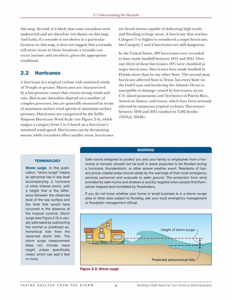
Storm surge. In this publi-cation, “storm surge” means an abnormal rise in sea level accompanying a hurricane or other intense storm, with a height that is the differ-ence between the observed level of the sea surface and the level that would have occurred in the absence of the tropical cyclone. Storm surge (see Figure 2-3) is usu-ally estimated by subtracting the normal or predicted as-tronomical tide from the observed storm tide. The storm surge measurement does not include wave height unless specifically noted, which can add 3 feet or more.
Figure 2-3: Storm surge
Safe rooms designed to protect you and your family or employees from a hur-ricane or tornado should not be built in areas expected to be flooded during a hurricane, thunderstorm, or other severe weather event. Residents of haz-ard-prone coastal areas should abide by the warnings of their local emergency services personnel and evacuate to safer ground. The protection from wind provided by safe rooms and shelters is quickly negated when people find them-selves trapped and inundated by floodwaters.
If you do not know whether your home or small business is in a storm surge area or other area subject to flooding, ask your local emergency management or floodplain management official.
WARNING

TA
KI
NG
S
HE
LT
ER
F
RO
M
TH
E
ST
OR
M
9
Building a S
afe Room
for Your Hom
e or Sm
all Business
2. Un
derstand
ing th
e Hazard
s
Figure 2-4: Typical damage associated with hurricane categories according to the Saffir-Simpson Hurricane Wind Scale (wind speeds are 1-minute sustained speeds) SOURCE: NOAA NATIONAL WEATHER SERVICE, NATIONAL HURRICANE CENTER
A high percentage of framed homes will be destroyed, with total roof failure and wall collapse. Fallen trees and power poles will isolate residential areas. Power outages will last for weeks to possibly months. Most of the area will be uninhabitable for weeks or months. (157 mph or higher)
Well-built framed homes may incur major damage or removal of roof decking and gable ends. Many trees will be snapped or uprooted, blocking numerous roads. Electricity and water will be unavailable for several days to weeks after the storm passes. (111–129 mph)
Well-built framed homes can sustain severe damage with loss of most of the roof structure and/or some exterior walls. Most trees will be snapped or uprooted and power poles downed. Fallen trees and power poles will isolate residential areas. Power outages will last weeks to possibly months. Most of the area will be uninhabitable for weeks or months. (130–156 mph)
Well-constructed framed homes could have damage to roof, shingles, vinyl siding, and gutters. Large branches of trees will snap and shallowly rooted trees may be toppled. Extensive damage to power lines and poles likely will result in power outages that could last a few to several days. (74–95 mph)
Well-constructed framed homes could sustain major roof and siding damage. Many shallowly rooted trees will be snapped or uprooted and block numerous roads. Near-total power loss is expected with outages that could last from several days to weeks. (96–110 mph)

T A K I N G S H E L T E R F R O M T H E S T O R M 10 Building a Safe Room for Your Home or Small Business
2. Understanding the Hazards
2.3 Effects of Extreme Winds on a Building
Extreme winds can cause severe damage to a building. For example, the roof covering, roof deck, or wall siding can be pulled off and the windows can be pushed into or pulled off of a building. Figure 2-5 shows how extreme winds can affect a building and cause it to fail. When wind enters a building through a broken window, door, or roof section, that wind acts on the inside of a building much like air acts when forced into a balloon; it pushes on the walls and roof of the building from the inside. These forces within the building added to the wind forces acting on the outside of the building often result in building failure. Buildings are generally not designed to resist forces acting on both the inside and the outside of the building.
Buildings that fail under the effects of extreme winds often appear to have exploded. This has given rise to the misconception that, during an extreme wind event, the windows and doors in a building should be opened to equalize the pressure and prevent atmospheric pressure differences from inside and outside the building.
In fact, opening a window or door allows wind to enter a building and increases the pressure acting on the interior of the building and the risk of building failure. This is illustrated in Figure 2-6, where the failure of a garage door initiated progressive failure that included the loss of the garage roof.
Damage can also be caused by flying debris. If wind speeds are extreme, debris can penetrate or perforate windows, walls, or the roof. For example, a 2-inch × 4-inch wood stud weighing 15 pounds, when carried
Figure 2-5: Effect of extreme winds on building roof and walls
Figure 2-6: Example of a garage door failure that initiated progressive failure, including loss of the garage roof

T A K I N G S H E L T E R F R O M T H E S T O R M 11 Building a Safe Room for Your Home or Small Business
2. Understanding the Hazards
by a 250-mph wind, can have a horizontal speed of 100 mph, which is enough force to penetrate or perforate most common building materials used in homes today. Even a reinforced masonry wall, which typically has hollow cells between reinforced cells, will be perforated unless it has been designed and constructed to resist debris impact during extreme winds. Because debris can severely damage and even perforate windows, walls, and roofs, they threaten not only buildings but the occupants as well.
2.4 Do You Need a Safe Room?
Building owners should ask themselves several questions when considering whether to install a safe room:
• What is my risk of tornadoes and/or hurricanes?
• What existing refuge options do I have if a tornado or hurricane occurs in my location?
• What level of safety am I comfortable with?
• How feasible is it to construct a safe room, and what are the costs?
On the basis of 60 years of tornado history and more than 150 years of hurricane history, the United States has been divided roughly into four zones that geographically reflect the number and strength of recorded extreme windstorms (Figure 2-7). Zone IV has experienced the most and the strongest tornado activity. Zone III has experienced significant tornado activity and includes most coastal areas that are susceptible to hurricanes. Zones II and I represent areas with relatively lower historical tornado activity that correlate with a lower risk of tornadoes in those areas. Zone II includes some areas east of the Rocky Mountains that are not covered in Zone III and parts of the northeast. Zone I primarily consists of areas west of the Rocky Mountains, where there are relatively few tornado occurrences. Additionally, the hurricane-prone region (as identified in Figure 2-7 along the Gulf Coast and Atlantic Coast) indicates substantial risk to hurricanes.
Section 2.5 includes guidance to help you determine your level of risk from these extreme events and will assist you in your decision whether or not to install a
safe room. If you decide that you need a safe room, Chapter 3 will help you and your builder/contractor or local design professional in planning your safe room. To learn more about the wind history for the area where you live, check with your local building official, meteorologist, or emergency management official. Also, visit the NOAA National Climatic Data Center, which contains data on various types of storms within the United States, at http://www.ncdc.noaa.gov/stormevents.
The prescriptive designs included in this publication should not be used to install safe rooms in hurricane-prone areas that may be inundated by storm surge or flooding from a hurricane. In areas not prone to storm surge, a safe room may be installed within mapped floodplains only when the designs provided herein meet the flood hazard criteria presented in Section 3.2, comply with all local floodplain ordinances, and are coordinated with local emergency management.
Your home or place of business may be built in accordance with local building codes that take into account the effects of minimum design winds for your area. Building codes require that buildings be able to withstand a “design” wind event. In most inland tornado-prone regions, the building code design wind speed (typically associated with a severe thunderstorm) is 115 mph in the latest editions of the IRC and IBC (2015 editions). For hurricane-prone areas, design wind speeds required by the 2015 IRC and 2015 IBC typically range from 115 mph to 180 mph. A tornado or
EVACUATION CONSIDERATIONS
A safe room may be designed and constructed to meet all applicable FEMA criteria. However, use of the safe room during an emergency event may not be in com-pliance with mandatory evacuation orders of the local jurisdiction. For instance, local emergency manage-ment officials may declare a mandatory evacuation prior to a hurricane event. FEMA recommends that all potential safe room occupants comply with local ju-risdictional directions and evacuation orders during an emergency event even if they have constructed a safe room.

TA
KI
NG
S
HE
LT
ER
F
RO
M
TH
E
ST
OR
M
12
B
uilding a Safe R
oom for Your H
ome or S
mall B
usiness
2. Un
derstand
ing th
e Hazard
s
Figure 2-7: Wind Zones in the United States** If you are uncertain of your location because of the level of
detail and size of the map, or if you live on or very near one of the delineation lines, use the highest adjacent wind zone.
T A K I N G S H E L T E R F R O M T H E S T O R M 13 Building a Safe Room for Your Home or Small Business
2. Understanding the Hazards
hurricane can cause winds much stronger than those on which local code requirements are based. Having a home built to the minimum requirements of the code does not mean that your home can withstand wind from extreme wind events. In addition to extreme wind speeds, tornadoes and hurricanes can produce significant wind-borne debris. Inland areas that are outside of the hurricane wind-borne debris region are not required by code to be designed to resist debris, which makes the protection of a safe room particularly important. The safe room designs in this publication provide a place to seek safe shelter during these extreme wind events.
Building codes are adopted at the local or State level in a process that takes model codes, such as the IRC and IBC, and accepts them as the local building code, often with amendments or modifications. With the incorporation of ICC 500 by referenced standard into the 2009, 2012, and 2015 IRC and IBC, States and local communities that adopt these codes with the reference to ICC 500 intact require any new facility designated as a tornado or hurricane storm shelter to be constructed to the requirements in ICC 500. ICC 500 codifies much of FEMA’s guidance for safe room design and construction. A safe room designed and constructed to the prescriptive designs included in this publication (and properly sited
to address flood hazards) will meet or exceed the ICC 500 residential storm shelter design criteria. For small businesses, community safe rooms, and safe rooms in residential buildings with more than 16 occupants, additional criteria are specified in ICC 500, including, but not limited to, ventilation, sanitation, and fire separation requirements. The designs in this publication are intended for residential safe room applications, and will not meet the necessary criteria for small business safe rooms without additional detailing and modifications.
2.5 Assessing Your Risk
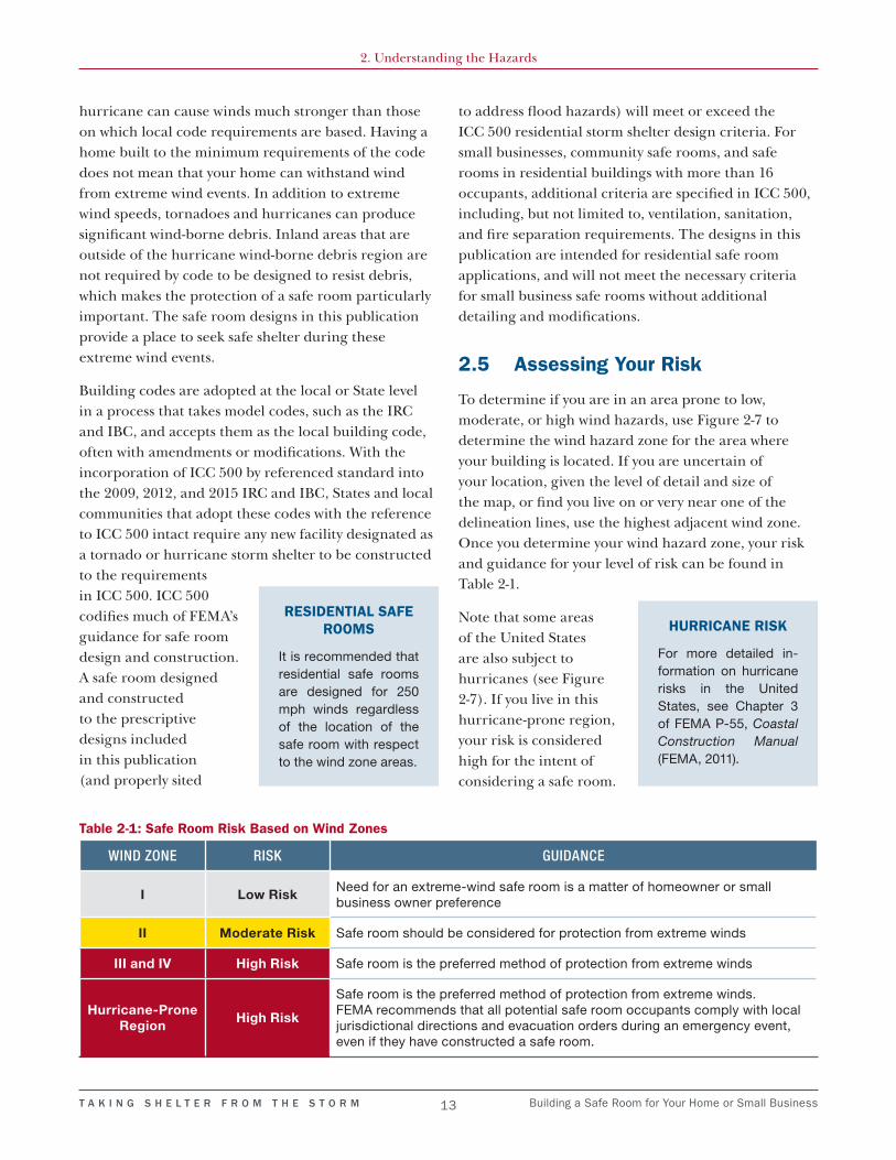
To determine if you are in an area prone to low, moderate, or high wind hazards, use Figure 2-7 to determine the wind hazard zone for the area where your building is located. If you are uncertain of your location, given the level of detail and size of the map, or find you live on or very near one of the delineation lines, use the highest adjacent wind zone. Once you determine your wind hazard zone, your risk and guidance for your level of risk can be found in Table 2-1.
Note that some areas of the United States are also subject to hurricanes (see Figure 2-7). If you live in this hurricane-prone region, your risk is considered high for the intent of considering a safe room.
RESIDENTIAL SAFE ROOMS
It is recommended that residential safe rooms are designed for 250 mph winds regardless of the location of the safe room with respect to the wind zone areas.
Table 2-1: Safe Room Risk Based on Wind Zones
WIND ZONE RISK GUIDANCE
I Low RiskNeed for an extreme-wind safe room is a matter of homeowner or small business owner preference
II Moderate Risk Safe room should be considered for protection from extreme winds
III and IV High Risk Safe room is the preferred method of protection from extreme winds
Hurricane-Prone Region
High Risk
Safe room is the preferred method of protection from extreme winds.FEMA recommends that all potential safe room occupants comply with local jurisdictional directions and evacuation orders during an emergency event, even if they have constructed a safe room.
HURRICANE RISK
For more detailed in-formation on hurricane risks in the United States, see Chapter 3 of FEMA P-55, Coastal Construction Manual (FEMA, 2011).

T A K I N G S H E L T E R F R O M T H E S T O R M 15 Building a Safe Room for Your Home or Small Business
CHAPTER 3Planning Your Safe Room
Now that you better understand your risk from a tornado or hurricane, you can work with your builder/contractor and local design
professional as necessary to build a safe room to provide protection for you, your family, or employees from these extreme windstorms. This section describes the basis of the safe room designs presented in this publication and shows you where you can build a safe room in your home or small business.
3.1 Design Basis
The purpose of a safe room is to provide a space where you, your family, or employees can survive a tornado or hurricane with little or no injury. To provide protection for the occupants during extreme windstorms, the safe room must be adequately anchored to a proper foundation to resist overturning and uplift; even when using the prescriptive designs in this publication, this may require the services of a licensed professional engineer. Further, the connections between all parts of the safe room must be strong enough to resist failure, and the walls, roof, and door must resist perforation by wind-borne debris.
Most homes, even new ones constructed according to modern building codes, do not provide adequate protection for occupants seeking life-safety protection from tornadoes. Homes built to a modern building code in hurricane-prone areas, such as wind-borne debris regions, better resist wind forces and wind-borne debris impacts from hurricanes. However, a
tornado or hurricane can produce wind and wind-borne debris loads on a home or small business that are much greater than those on which building code requirements are based. Only specially designed and constructed safe rooms that are built above the minimum code requirements of the IBC and IRC to the criteria of this publication, FEMA P-361, or the ICC 500, offer life-safety occupant protection during a tornado or strong hurricane. The safe room
DESIGN REQUIREMENTS
This publication provides FEMA safe room designs that meet or exceed the minimum residential shelter design requirements from FEMA P-361 and ICC 500.
The safe room designs in this publication are appli-cable for both tornado and hurricane hazards for the residential shelter (with 16 or fewer occupants) design criteria identified in FEMA P-361 and ICC 500.
The safe room design wind speed used for these designs is 250 mph. The safe rooms have been de-signed as “partially enclosed buildings” per ASCE 7 to meet the requirements of both residential and com-munity safe rooms for tornado and hurricane hazards. Further, the debris impact resistance is based upon the 15-pound 2-inch × 4-inch board missile traveling horizontally at 100 mph (again, the most restrictive cri-teria for both tornado and hurricane hazards).
For additional design criteria and information for resi-dential safe rooms, see FEMA P-361.

T A K I N G S H E L T E R F R O M T H E S T O R M 16 Building a Safe Room for Your Home or Small Business
3. Planning Your Safe Room
designs provided in this publication are based on wind speeds that are rarely exceeded in the United States. Therefore, a safe room built in accordance with these designs is expected to withstand the forces imposed on it by extreme winds without failing; this statement applies to both materials and connections used within the safe room. The intent of the designs is to enable the safe room occupants to survive an extreme windstorm with minor or no injuries, not for the safe room to remain completely undamaged.
Predicting the exact strength of tornadoes and hurricanes is very difficult due to the complex nature of the storms. That is another reason why the safe room designs in this publication are based on extreme wind speeds and why the primary consideration is life safety.
Designing a building, or portion of a building, to resist damage from more than one natural hazard requires different, sometimes competing, approaches. For example, building a structure on an elevated foundation to raise it above expected flood levels can increase its vulnerability to wind and seismic damage. In flood-prone areas, careful attention should be given to the warning time, velocity, depth, and duration of floodwaters. These flooding characteristics can have a significant bearing on the design and possibly even the viability of a safe room. These considerations, among others, should be thoroughly evaluated during the design process. Your local building official or licensed professional engineer or architect can provide you with information about other natural hazards that affect your area and can also recommend appropriate foundation designs and connections to resist prevailing hazards and conditions in your area.
3.2 Flood Hazard Siting and Elevation
A residential safe room should not be placed in any of the flood hazard areas listed in Section 3.2.1. Residential safe rooms located in a flood hazard area that is not listed in Section 3.2.1 should be elevated per the criteria listed in Section 3.2.2.
The placement of a safe room in a new or existing home should be scrutinized with respect to flood
hazards. The designer should also ensure that the safe room will withstand the forces of extreme winds and floodwaters in the event that the main homes is damaged or destroyed.
If your residential tornado safe room is in an area that could become flooded during hurricanes, it should not be occupied during any hurricane. The installation of any safe room in the hurricane-prone region should be coordinated with local emergency management and law enforcement personnel to ensure its use during extreme wind events is not a violation of any local or State evacuation plan.
A residential safe room sited in the Special Flood Hazard Area (SFHA) should meet the flood-specific FEMA safe room design criteria listed in Section 3.2.2. Consult your local building official or local floodplain manager to determine whether your home, small business, or proposed stand-alone safe room site, is susceptible to coastal, riverine, or surface water flooding.
3.2.1 Flood Hazard Siting Criteria
A residential safe room should be located outside the following high hazard areas:
• Flood hazard areas subject to high-velocity wave action (Zone V1) and Coastal A Zones (where mapped)
• Floodways
• Any areas subject to storm surge inundation associated with any modeled hurricane Category, including coastal wave effects (where applicable, these areas should be mapped areas studied by the U.S. Army Corps of Engineers, NOAA, or other qualified agency)
1 For the purpose of this publication, Zone V refers to Zones V, VE, and V1-30.
Whenever a safe room is constructed using FEMA grant funds, the recommended criteria shown in Section 3.2 become requirements.

T A K I N G S H E L T E R F R O M T H E S T O R M 17 Building a Safe Room for Your Home or Small Business
3. Planning Your Safe Room
3.2.2 Flood Hazard Elevation Criteria
If it is not possible to place the residential safe room outside the SFHA, the residential safe room may be placed in an area that has been determined to be in Zone A,2 but still outside the high hazard areas identified in Section 3.2.1. In cases when a residential safe room is needed in these flood-prone areas, the safe room should be elevated to or above the highest elevation specified below (refer to the appropriate Flood Insurance Study or Flood Insurance Rate Map):
• The minimum elevation of the lowest floor required by the authority having jurisdiction (AHJ) for the location where the shelter is installed
• The base flood elevation (i.e., the flood elevation having a 1-percent annual chance of being equaled or exceeded [100-year event])
• The flood elevation, including coastal wave effects, having a 0.2-percent annual chance of being equaled or exceeded (500-year event)
• The flood elevation corresponding to the highest recorded flood elevation if a flood hazard study has not been conducted for the area
2 For the purpose of this publication, Zone A refers to Zones A, AO, AH, A1–30, AE, A99, AR, AR/A1–30, AR/AE, AR/AH, and AR/A, but excludes Coastal A Zones.
The prescriptive designs presented in this publication can only be elevated a few feet above existing grade (see design drawings for specific details and elevation limitations) and, therefore, may not comply with flood design criteria for residential safe rooms. In such a situation, alternatives would be to: 1) have a structural engineer design a site-specific foundation for the safe room, or 2) in cases where flow velocity and erosion are not expected during design conditions, build an exterior weatherproof safe room on a slab-on-grade elevated on fill above the flood elevation specified above. Furthermore, the safe room should not be used if local emergency management officials call for the evacuation of an area prior to a hurricane event.
3.3 New versus Existing Homes or Buildings
By constructing a safe room within your home or small business, you are protecting your family and/or employees from extreme wind events. A safe room may be installed during the initial construction of a home or retrofitted afterward. As long as the design and construction requirements and guidance are followed, the same level of protection is provided by either type of safe room. For this discussion, “retrofit” refers to the process of making changes to an existing building.
The safe room designs in this publication were developed primarily for use in new homes or buildings, but some can be used in existing buildings. When a
RESIDENTIAL TORNADO SAFE ROOM EXCEPTION
Where a residential tornado safe room is designed, constructed, and used only as a tornado safe room, it does not have to be elevated to the flood elevation, including coastal wave effects, having a 0.2-percent annual chance to being equaled or exceeded in any given year (500-year event).
SOURCES OF FLOOD HAZARD MAPS
Flood hazard maps for your area can be obtained from multiple sources, including:
• FEMA Map Service Center (https://msc.fema.gov)
• Local or State Emergency Management Agencies
• Floodplain managers (http://www.floods.org)
• Local building or zoning department
Where the 1-percent and/or 0.2-percent annual chance flood elevations have not been determined by a flood hazard study, those elevations should be obtained from the authority having jurisdiction or calculated.
FLOOD CRITERIA FOR SAFE ROOMS IN SMALL BUSINESSES
The flood criteria provided in this publication applies to residential safe rooms. Community safe room de-signs, including safe rooms installed in residential buildings for more than 16 occupants, should refer-ence the community safe room flood hazard siting and elevation criteria provided in FEMA P-361.

T A K I N G S H E L T E R F R O M T H E S T O R M 18 Building a Safe Room for Your Home or Small Business
3. Planning Your Safe Room
new home is being built, the builder/contractor can construct walls, foundations, and other parts of the home to accommodate the safe room. Modifying the walls or foundation of an existing home as necessary for the construction of a safe room is more difficult. As a result, some of the safe room designs in this publication are not practical for existing homes.
Adding a safe room when first building your home or small business is relatively easy and cost-effective. For example, when the home is constructed with exterior walls made from concrete masonry units (CMUs) (also commonly known as “concrete block”; see Figure 3-1), the protection level in FEMA P-320 can be achieved by slightly modifying the exterior walls at the safe room space with additional steel reinforcement and grout. The safe room is easily completed by adding interior walls constructed of reinforced CMU, a concrete roof deck over the safe room, and a special safe room door, as shown in Figure 3-2.
Building a safe room in an existing home typically costs more than building the same safe room in a new home under construction. When installing a safe room in an existing home, the adequacy of the foundation is a primary concern. The vast majority of slab-on-grade foundations in homes are not designed to transfer the
loads from the safe room to the ground, even if they have some level of reinforcement. Retrofitting these slabs is often not feasible, and in many cases a portion of the slab must be cut out where the safe room will be, and a new, thicker, reinforced slab with footings must be poured for the safe room. Note that some safe rooms may be heavy enough that an existing slab may be used. Designers can take advantage of this if the dead load (weight) of the safe room, without the weight of the slab, is sufficient to resist the overturning forces on the safe room during a design event. This can frequently be accomplished when the walls of the safe room are CMU or concrete. If you plan on taking advantage of this circumstance, you should have a licensed professional engineer or architect verify that the safe room to be constructed does indeed meet these requirements.
Figure 3-1: Exterior walls constructed of CMUs (New Smyrna Beach, FL, 2007)
CONCRETE SLAB-ON-GRADE REQUIREMENTS FOR SAFE ROOMS
In addition to requiring any slab used for a storm shel-ter to be designed and reinforced with steel, ICC 500 also requires any storm shelter installed on an existing slab using post-installed anchors (anchors installed in concrete that has already hardened) to be subject to special inspections.

T A K I N G S H E L T E R F R O M T H E S T O R M 19 Building a Safe Room for Your Home or Small Business
3. Planning Your Safe Room
Figure 3-2: In-home safe room under construction; the CMU walls of the safe room are fully grouted and vertically reinforced with steel reinforcing bars from the foundation to the concrete roof deck (New Smyrna Beach, FL, 2007)
USABLE SPACE
Consult FEMA P-361 for guidelines on how to iden-tify the net usable floor space and other requirements for a safe room design. Hard fixtures and furnishings reduce the square footage within a safe room that is available for protecting occupants.
3.4 Safe Room Size
The amount of floor area per person that your safe room must provide depends partly on the type of windstorm from which the safe room is intended to protect you.
Tornadoes are not typically long-lasting storms, so if you are relying on your safe room only for tornado protection, you will not need to stay in the safe room for as long as you would for a hurricane. As a result,

T A K I N G S H E L T E R F R O M T H E S T O R M 20 Building a Safe Room for Your Home or Small Business
3. Planning Your Safe Room
comfort is not of a primary concern, and a safe room that provides at least 3 square feet of floor area per person for one- and two-family dwellings should be large enough (note that safe rooms in other residential host buildings, such as apartment buildings, should be afforded at least 5 square feet per person). This allocation of space per occupant also meets the minimum sizing requirements set forth in ICC 500 for residential tornado storm shelters.
When the safe room is intended to provide protection from storms such as hurricanes, which can last for 24 hours or more, the comfort of the occupants should be considered. For a residential hurricane safe room, the recommended amount of floor area per person varies from 7 to 10 square feet, depending on whether the residential hurricane safe room is located in a one- or two-family dwelling or another type of residential building such as an apartment building (as long as the maximum occupancy of the safe room does not exceed 16 people). The minimum sizing requirement set forth in ICC 500 for residential hurricane shelters is 7 square feet per occupant, while for community shelters 20 square feet per occupant is specified for standing or seated and wheelchair-bound occupants and 40 square feet per occupant for bed-ridden occupants. Necessities, such as water and toilet facilities, need to be provided in small business safe rooms to maintain compliance with FEMA P-361 criteria and ICC 500 requirements.
The safe room designs in this publication have a gross area of at least 64 square feet and a minimum wall length of 8 feet (for both tornado and hurricane hazards). The maximum floor dimensions in the safe room designs provided in this publication are 14 feet × 14 feet square, providing 196 square feet of gross safe room space. As indicated in the Introduction, the occupant load for residential safe rooms must be no
more than 16 occupants (regardless of dimensions). If you plan to build a residential safe room outside the dimensions of the drawings provided in this publication, or if you plan to have more than 16 occupants in your residential safe room, consult a licensed professional engineer or architect. More information on the sizing of safe rooms in the design drawings is presented in Chapter 4.
3.5 Safe Room Locations
For tornado-prone areas, you should locate your safe room so that you can reach it as quickly as possible from all parts of your home or business, and it should be free of clutter. When determining the siting of a safe room, also consider the accessibility needs of potential occupants. For example, for occupants who use wheelchairs or crutches, the use of stairs in an in-ground safe room may make it difficult to access the safe room in a short amount of time.
3.5.1 Siting Your Safe Room: Inside or Outside?
While there are a number of potential locations to construct a safe room inside of a home or small business, a safe room can also be located outside of the building, either as a detached structure (i.e., away from the building) or adjacent to the building. Keep in mind that occupants will need to travel to the safe room from the building, which is why ICC 500 requires that residential safe rooms be located such that the travel distance from the access opening for the safe room to
COMMUNITY SAFE ROOMS
Safe rooms for small businesses or residential use with more than 16 occupants are Community Safe Rooms that have additional requirements that the designs in this publication do not provide for, including, but not limited to, ventilation, sanitation, and fire separation.
IN-GROUND SAFE ROOMS
In-ground safe rooms referred to in this publication are slightly different from basement safe rooms be-cause they are buried underground and surrounded by soils on all sides. Basement safe rooms are in a basement but are not surrounded by soil on all sides.
In-ground safe rooms are not covered in the de-sign drawings because prefabricated in-ground safe rooms are more common and easily constructed for residential applications than site-built in-ground safe rooms. For more information on prefabricated safe rooms, see Section 4.3.

T A K I N G S H E L T E R F R O M T H E S T O R M 21 Building a Safe Room for Your Home or Small Business
3. Planning Your Safe Room
the nearest entrance of the residence does not exceed 150 feet. Safe rooms located exterior to the home or business require early access to prevent injuries from wind and debris. Like interior safe rooms, exterior safe rooms can be either above- or in-ground. However, if you are located in a SFHA (as outlined in Section 3.2), siting the safe room below ground or below the design flood elevation is not recommended.
While an interior safe room has the benefit of being closer to the building occupants, an exterior safe room may be easier to install for an existing home. An interior safe room constructed in an existing home would typically require substantial retrofitting. By contrast, a separate, detached safe room located outside a home would not require modifications to the home and can therefore be more affordable and feasible for existing buildings. These could even be added onto a new or existing covered porch or patio. Safe rooms located outside of a building also require exterior weather protection per minimum building code requirements. The protection required will depend on local code requirements as well as the type of material used for the exterior walls and roof. Per ICC 500, hurricane safe rooms require weather protection against the design event for any areas of an exposed building envelope, but interior residential safe rooms that are fully enclosed by the host building (i.e., no portion of the safe room wall or roof is also an exterior wall or roof of the building in which the safe room is located) do not require exterior weather protection. Prefabricated versions for both indoor and outdoor safe rooms are available and can be more affordable than site-built versions.
Safe room entrance locations should be considered along with the location of the safe room itself. Entrances that are accessible without having to go outside and be exposed to potential wind and debris are preferable, though may not be feasible in all cases. Safe rooms placed adjacent to the main building could have an entrance directly into the safe room from the main building, or it could have an entrance from the outside as shown in Figure 3-3.
3.5.2 Siting a Safe Room Inside a Home or Small Business
There are several possible locations within your home or small business for a safe room. It can be either inside (within the building footprint) or outside (detached or adjacent to the existing building), and above-ground, in-ground, or in a basement. While in-ground safe rooms provide the inherent missile protection naturally afforded by the surrounding soil coverage, above-ground safe rooms are required to be rigorously tested to ensure that they can also provide missile impact protection. Therefore, all properly constructed safe rooms offer life safety protection when properly designed and constructed. This is an important alternative to be aware of if you are not able to install a safe room in your basement or in-ground because of issues such as flood hazards, naturally high groundwater tables, or the physical abilities of potential occupants at your site.
Researchers, emergency response personnel, and people cleaning up after tornadoes have often found small, interior rooms of a home or small business still standing when all other above-ground parts of the home or small business have been destroyed (see Figure 3-4).
Figure 3-3: An above-ground safe room constructed as an addition to a slab-on-grade home in a way that matches the aesthetics of the home (outside Tuscaloosa, AL, 2011)

T A K I N G S H E L T E R F R O M T H E S T O R M 22 Building a Safe Room for Your Home or Small Business
3. Planning Your Safe Room
Regardless of where in your home or small business you build your safe room, the walls and ceiling of the safe room must be built so that they will protect you, your family, or employees from wind-borne and falling debris, be anchored to an adequate foundation, and
remain standing if your home or small business is severely damaged by extreme winds (see Figure 3-5). Closets, bathrooms, and small storage rooms offer the advantage of having a function other than providing occasional storm protection. Typically, these rooms have only one door and no windows, which makes them well suited to also be a safe room in addition to their regular function. Bathrooms have the added advantage of including a water supply and toilet. If sections of your home’s or small business’ walls are used as safe room walls, those wall sections must be designed for the wind pressure and debris impact resistance outlined in FEMA P-361. Similarly, if you construct a safe room on the first floor of a building above a basement, the structure below the safe room that carries the loads down to the foundation must be capable of resisting the same wind loads as the safe room. As outlined in ICC 500, any connections between the safe room and host building must be designed to resist higher loads than minimum building code requirements. This is to ensure the structural integrity of the safe room, should the rest of the structure fail or be compromised during an extreme wind event.
Figure 3-4: Core remnants of homes sometimes survive a tornado as shown in these photographs of site-built homes where a closet (red arrow in left photograph) and a bathroom behind a kitchen (red arrow in right photograph) remained standing after an EF4 tornado (Tuscaloosa, AL, 2011)
Figure 3-5: Above-ground residential safe room that was in the garage of a home hit by an EF5 tornado in Joplin, MO (2011)

T A K I N G S H E L T E R F R O M T H E S T O R M 23 Building a Safe Room for Your Home or Small Business
3. Planning Your Safe Room
3.6 Floor Plans Showing Possible Safe Room Locations
This section shows four typical floor plans with possible locations for safe rooms. These are not floor plans developed specifically for homes with safe rooms; rather, they show how safe rooms can be added without changing the layout of rooms. Regardless of where the safe room is built, it must be equipped with a door that has been tested and certified to the appropriate criteria and will resist the wind pressure and impact of wind-borne debris. See Section 3.9 for more information on selecting a door for your safe room.
3.6.1 Floor Plan 1: Basement
Possible safe room locations in a basement are shown in Figure 3-6 and include the following:
• A space using one or more exterior walls of the basement
• A freestanding structure within the basement (not using the basement walls)
A space that is to be used for a safe room must be kept free of clutter so that the safe room can be quickly and easily entered and so that the safe room occupants will not be injured by falling objects. For this reason, a bathroom is often a better choice for a safe room than a closet or other space used for storage. Basements are not suitable locations for safe rooms when there is a flood hazard risk present. For more information on flood hazards to consider, please see Section 3.2.
3.6.2 Floor Plan 2: Safe Rooms on the Primary Level of a Home or Small Business
Possible safe room locations in a home on a slab-on-grade or crawlspace foundation are shown in Figure 3-7 and include the following spaces on the first floor:
• Bathroom
• Closet
• Laundry room (provided the load-bearing wall between it and the garage, as shown in Figure 3-7, can be properly strengthened or separated from the structure of the home)
• Corner of the garage
• Outside within 150 feet travel distance from the home
3.6.3 Floor Plan 3: In-Ground Safe Rooms
Possible locations for an in-ground safe room are shown in Figure 3-8 and include the following:
• Below the home
• Below the floor of the garage
• Below ground within 150 feet travel distance from the home
Figure 3-6: Floor Plan 1: Possible safe room locations in a basement
Figure 3-7: Floor Plan 2: Home on a slab-on-grade or crawlspace foundation

T A K I N G S H E L T E R F R O M T H E S T O R M 24 Building a Safe Room for Your Home or Small Business
3. Planning Your Safe Room
When deciding whether to choose an in-ground safe room, make sure the potential for flooding is considered (see Section 3.2 for more information). Also note that for safe rooms located in garages, any potential obstacles (such as a parked car) should be considered as well as the possible need to reinforce the garage floor in order to park a car. In the event of a tornado, the safe room user may be blocked from entering and exiting the safe room.
3.6.4 Floor Plan 4: Multipurpose Safe Rooms in a Small Business
Small businesses can use prescriptive safe room designs for multipurpose safe rooms. Figure 3-9 illustrates some potential locations for a safe room in a fire station. The area used for a conference room or other purpose can also be adapted for life-safety protection, provided the equipment and fixtures placed in the safe room can be removed quickly and efficiently. When placing safe rooms in buildings larger than typical residential structures, the layout should be designed so that the safe room is quickly accessible from other areas on the floor. FEMA P-361 and ICC 500 provide additional requirements that apply to community safe rooms, such as ventilation, fire protection, sanitation, and minimum usable area per occupant. Although an emergency escape opening is not required in FEMA P-361 or ICC 500 for safe rooms with less than 16 occupants, Section 501.2 of ICC 500 requires an emergency escape
opening (an additional door or other opening) for storm shelters with more than 16 occupants, when the applicable building code only requires one exit door.
3.6.5 Selection of Safe Room Type and Location
Table 3-1 will help you decide what type of safe room is appropriate for your circumstances. The top section applies to the construction of safe rooms in new homes or buildings. The bottom section provides considerations for retrofit situations, in which a safe room is being added to an existing home or building.
Table 3-2 will also help you consider the options of connections to a home (or small business), exposure (above or below ground), construction type, applicability to new or existing buildings, and access (depending on whether the safe room is inside or outside of the building). The right-most column in the table also indicates whether this publication has a safe room prescriptive solution that applies to this type of safe room.
Figure 3-8: Floor Plan 3: Possible in-ground safe room locations in a home without a basement
Figure 3-9: Floor Plan 4: Multipurpose safe room locations in a fire station

T A K I N G S H E L T E R F R O M T H E S T O R M 25 Building a Safe Room for Your Home or Small Business
3. Planning Your Safe Room
Table 3-2: Construction, Applicability, and Access for Safe Rooms
CONNECTION TO HOME
1 This publication does not contain any designs for site-built in-ground safe rooms, as prefabricated in-ground safe rooms are typically more constructible and affordable.
2 Per flood design criteria for FEMA safe rooms (see Section 3.2), elevation of a safe room is only permitted when specific flood design criteria have been met and when approved by the jurisdictional authority responsible for evacuations and NFIP compliance.
EXPOSURE
CONSTRUCTION APPLICABILITY ACCESS FEMA P-320 SAFE ROOM
APPLICATIONSPREFABRICATEDSITE-BUILT
NEW HOME
EXISTING HOME
INSIDE HOME
OUTSIDE HOME
DetachedAbove ground Yes Yes Yes Yes No Yes Yes
In ground Yes Yes Yes Yes No Yes No
Below In ground Yes Yes Yes Yes Yes Yes No
InsideIn basement Yes Yes Yes Yes Yes Yes Yes
Above ground Yes Yes Yes Yes Yes Yes Yes
Attached Above ground Yes Yes Yes Yes Yes Yes Yes
Table 3.1 Appropriate Types of Safe Rooms for New and Existing Homes and Buildings
APPROPRIATE SAFE ROOM TYPE
SAFE ROOM CONSIDERATIONS (NEW HOMES OR BUILDINGS) BASEMENT IN-GROUND1 ABOVE-GROUND
House or building located in a storm surge area
House or building located in a flood hazard area2
High water table
Low cost
Long-term safe room occupancy comfort
Least likely to be hit or impacted by wind-borne debris
Ease of accessibility (pre- and post-event)
APPROPRIATE SAFE ROOM TYPEAPPROPRIATE SAFE ROOM TYPE
SAFE ROOM CONSIDERATIONS (EXISTING HOMES OR BUILDINGS) BASEMENT IN-GROUND1 ABOVE-GROUND
House or building located in a storm surge area
House or building located in a flood hazard area2
High water table
Low cost
Long-term safe room occupancy comfort
Least likely to be hit or impacted by wind-borne debris
Ease of separating safe room from structural framing of house or building
Minimal disruption to house or building
Ease of accessibility (pre- and post-event)
Favorable Some concerns Unfavorable Not appropriate

T A K I N G S H E L T E R F R O M T H E S T O R M 26 Building a Safe Room for Your Home or Small Business
3. Planning Your Safe Room
3.7 Foundation Type In a new home with a basement, the safe room is often built in the basement. You can build the safe room as
Homes and other buildings vary in construction type an entirely separate structure with its own walls, or you as well as foundation type. Buildings may have heavy can use one or more of the basement walls as walls of wall systems, such as masonry or concrete, or they may the safe room (see Figure 3-10). Vertical and horizontal have light wall systems, such as wood framing, metal surfaces with sufficient soil cover do not have to be stud framing, or structural insulated panels. Regardless tested for resistance to debris impact (see Chapter B3 of the structure type noted above, the following types of FEMA P-361 for more information), though they of foundations may be suitable for the installation of a still need to be able to resist the extreme wind loads. safe room: Typical reinforcement techniques used in existing
• Basement residential basement walls will not provide sufficient resistance to extreme wind loads. For new construction, • Slab-on-grade with footings and reinforcementyour builder/contractor can reinforce the walls used for
• Crawlspace or pile (however, prescriptive solutions the safe room. For existing construction, reinforcing for pile foundations are not included in this the walls is often not feasible and where possible is publication) typically cost-prohibitive.
3.7.1 Basement Foundation Applications
A home on a basement foundation is usually built on a foundation constructed of cast-in-place concrete or CMUs. Existing foundation walls will likely not meet the requirements for a safe room. The framing for the floor above the basement is supported by the exterior foundation walls and sometimes by beams or interior walls.
The likelihood of wind-borne debris entering the basement is lower than for above-ground spaces;
Figure 3-10: Cross section: Typical new construction basement foundation with safe room (reinforcement shown for illustrative purposes only)
EXISTING SPACES
When determining whether an existing wall, founda-tion, or roof can be used for a safe room, the specific existing configuration must be carefully evaluated to determine its capacity. The proposed safe room should be planned as a structurally separate space to prevent it from relying on existing components that were designed to provide much lower levels of perfor-mance. Any existing building elements that would be structurally relied upon by the safe room would likely need to be replaced.
BASEMENT WALLS
Reinforcement used in typical basement walls for nor-mal use will not provide sufficient resistance for safe rooms. In order to economically utilize basement walls as part of a safe room, the safe room should be in-tegrated into the design and construction process during the new construction phase.

T A K I N G S H E L T E R F R O M T H E S T O R M 27 Building a Safe Room for Your Home or Small Business
3. Planning Your Safe Room
however, a basement safe room should still be designed to resist the extreme wind pressures that an above-ground safe room would need to resist. The safe room designs provided in this publication considered that loading from debris may be experienced by the safe rooms when a surrounding structure collapses during an extreme wind event. The roof decks of these safe rooms are designed to limit the damage that may be induced from these debris sources; therefore, the existing first floor of a home would not be adequate to also serve as the roof of the safe room unless it has been designed to the criteria in FEMA P-361. Although the building may collapse around the safe room, installing the safe room in the basement is still appropriate if it is designed and constructed to perform independently of the structure that surrounds it.
In addition to the roof and exterior walls, the foundation of a basement safe room should be adequate to resist the overturning and uplift forces of an extreme wind event. If the basement has an unreinforced or insufficiently reinforced slab of typical thickness (approximately 4 inches), there may not be enough dead load in the safe room to resist these forces. In general, adding a basement safe room during the construction of a new home is easier than retrofitting the basement of an existing home. If you
plan to add a basement safe room as a retrofitting project, keep the following in mind:
• You must be able to clear out an area of the basement large enough for the safe room.
• Unless the exterior basement walls contain adequate reinforcement as shown on the design drawings provided with this publication, these walls cannot be used as safe room walls because they are not reinforced to resist damage from wind-borne debris and extreme winds uplifting the home’s floor structure above.
• Exterior basement walls that are used as safe room walls must not contain windows, doors, or other openings in the area providing protection unless they are protected with an appropriate protective device or are designed to resist the debris impact and pressure associated with safe room design.
• The roof of the safe room must be designed to resist the wind pressures and debris impact forces.
3.7.2 Slab-on-Grade Applications
A slab-on-grade home or commercial building (see Figure 3-11) is built on a concrete slab that is constructed on compacted or undisturbed soil.
Figure 3-11: Cross section: Typical slab-on-grade foundation with safe room (reinforcement shown for illustrative purposes only)

T A K I N G S H E L T E R F R O M T H E S T O R M 28 Building a Safe Room for Your Home or Small Business
3. Planning Your Safe Room
Concrete slabs require steel reinforcement (as required in ICC 500) to prevent cracking and to resist the tension resulting from extreme wind loads acting on the safe room. If you are building a new slab-on-grade home and want to install a safe room (of any material or type), FEMA recommends that the slab or foundation beneath the safe room be adequately reinforced and be thickened or have footings to ensure proper support and resistance to all loads (gravity and wind loads). A licensed design professional will help provide these details. The thickened slab will act as a footing beneath the walls of the safe room to provide structural support. It will also help anchor the safe room so that it will stay in place during an extreme wind event, even if the rest of the home is destroyed.
In an existing home, removing part of the slab and replacing it with a thickened section or footing to support a safe room would involve some disruption inside the home. Building a safe room, particularly with lightweight wood-framed walls, in an existing slab-on-grade home may not be practical unless a new slab is poured or the existing slab can be shown to have reinforcement and thickness adequate to support the safe room. If steel reinforcement in an existing slab is present and documented, the designs provided in these plans may be retrofitted to certain reinforced slabs.
In some cases, heavy safe rooms that do not require the dead load of the slab for resistance may be installed on existing slabs, as discussed in Section 3.3. Lighter safe rooms may require more dead load (weight of the structure and slab or foundation) to resist uplift, overturning, and sliding forces. This dead load can be attained by installing a thickened slab foundation or footings under the walls of the safe room. Whenever an existing slab is used as the foundation for a safe room, ICC 500 requires a Special Inspection be provided to review and verify the following: 1) engineering calculations proving the adequacy of the existing slab to resist the applicable loads, 2) the minimum required thickness of the slab, 3) the presence of required reinforcing steel, and 4) the installation and capacity of the safe room anchors. Where a thicker or reinforced foundation is needed, the existing slab should be cut out around the perimeter of the safe room, and a mat-slab or footings and slab should be installed.
You can also build a safe room as an addition to the outside of a slab-on-grade home (as shown in Figure 3-3). This type of safe room must not only have proper footings, but also exterior weather protection (for more information on exterior safe rooms, see Section 3.5.1). In general, adding a safe room during the construction of a new slab-on-grade home is easier than retrofitting an existing slab-on-grade home. If you plan to add a safe room to a slab-on-grade home as a retrofitting project, keep the following in mind:
• The walls of the safe room must be completely separate from the structure of the home unless the existing walls have adequate reinforcement or are reinforced as part of the retrofit to meet the safe room criteria.
3.7.3 Crawlspace or Pile Applications
A home built on a crawlspace (see Figure 3-12) usually has a floor constructed of wood framing. Along its perimeter, the floor is supported by the exterior foundation walls. The interior part of the floor is supported by beams that rest on a foundation wall or individual piers. Crawlspace foundation walls may be concrete, but are usually constructed of CMU blocks. They are often unreinforced and provide little resistance to the stresses caused by extreme winds.
Building a safe room inside a home on an existing crawlspace foundation is very complicated. The main reason is that the entire safe room, including its floor, must be separate from the framing of the home or, alternatively, the entire floor system and foundation of the home must be constructed to support the extreme wind loads acting on the safe room. In Figure 3-12, a safe room is built inside the home or commercial building without using the floor system of the structure itself. In this option, the safe room has a separate
SOIL CHARACTERISTICS
While heavier safe rooms, such as those constructed of concrete and CMU, are more likely to resist forces imparted by extreme wind pressures, a local design professional may need to verify that the soil will be able to carry the weight of the safe room.

T A K I N G S H E L T E R F R O M T H E S T O R M 29 Building a Safe Room for Your Home or Small Business
3. Planning Your Safe Room
Figure 3-12: Cross-section: Typical crawlspace foundation with safe room (reinforcement shown for illustrative purposes only)
concrete slab floor installed on top of compacted earth fill and must be supported by steel reinforced concrete or CMU foundation walls. The floor system may be designed as open and elevated, but that design option is difficult to develop a prescriptive solution for and, therefore, is not addressed in this publication. An alternative approach, which may be more economical, is to build an exterior safe room on a reinforced slab-on-grade foundation adjacent to an outside wall of the home and provide access through a door installed in that wall.
Ventilation in the area below the floor of the home is also an important issue. The wood-framed floor of a home on a crawlspace foundation is typically held 18 to 30 inches above the ground by the foundation walls for compliance with the building code. The space below the floor is designed to allow air to flow through so that the floor framing will not become too damp. This air flow must not be blocked by the installation of the safe room.
In general, building a safe room inside a new crawlspace home is easier than building a safe room in an existing crawlspace home. If you plan to add a safe room to an existing crawlspace home as a retrofitting project, keep the following in mind:
• The safe room must have a separate foundation. Building the foundation inside the home would require cutting out a section of the existing floor and installing new foundation members, fill dirt, and a new slab—a complicated and expensive operation that is often not practical.
• A more practical and more economical approach would be to build an exterior safe room, made of concrete or concrete masonry, on a slab-on-grade foundation adjacent to an outside wall of the home, as described above.
xtensive testing by wind engineering research facilities as shown that walls, ceilings, and doors commonly sed to meet minimum building code requirements
or standard building construction cannot withstand xtreme wind pressures or the impact of debris carried y these extreme winds. The safe room designs in this ublication account for these findings by specifying uilding materials or combinations of building aterials that will resist wind forces and perforation by
ebris in extreme winds.
3.8 Construction Materials
Ehufebpbmd

T A K I N G S H E L T E R F R O M T H E S T O R M 30 Building a Safe Room for Your Home or Small Business
3. Planning Your Safe Room
SAFE ROOM MATERIALS
The materials your builder/contractor will need to build your safe room should be available from building material suppliers in your community. These materials have been carefully selected for their strength, dura-bility, and/or ability to be readily combined in ways that enable them to withstand the forces of extreme winds and the impact of wind-borne debris. Your builder/contractor should not substitute any other ma-terial for those specified in the designs.
Since the first edition of FEMA P-320 was released in 1998, many tornado events have occurred, highlighting the importance of installing safe rooms in homes or small businesses. Individuals and companies began designing safe rooms to provide alternatives to the prescriptive solutions presented here. As a result, a residential safe room industry has evolved.
Many of the safe room products are designed and constructed as prefabricated units. These prefabricated units are constructed from a variety of materials, such as metal panels, concrete, fiberglass shells, and many more. These other safe room types use common building materials or new innovations from the building industry. The design drawings in this publication provide prescriptive solutions for site-built safe rooms and specify the construction materials for the various safe room types. However, safe room doors are not included in the prescriptive designs and must also comply with the debris impact and pressure test criteria that are discussed further in Section 3.9.
PREFABRICATED SAFE ROOMS
Additional information regarding prefabricated safe rooms is presented in the Consumer Guide in Chapter 4 of this publication.
Remember that, as with site-built safe rooms and shelters, prefabricated shelters must be attached to an appropriate foundation. A structural engineer should always be consulted to ensure that the prefab-ricated shelter is being installed on an appropriate and adequate foundation.
3.9 Safe Room Doors
Like any other room, safe rooms must be accessed through an opening or door. Just as the walls and roof of a safe room are designed and built to protect against extreme winds and wind-borne debris, so must the safe room door and assembly. The door assembly includes the door, hardware (locks and hinges), frame, and attachment devices used to anchor the door frame to the surrounding safe room wall. When careful selection and installation of the safe room door assembly is overlooked, a door failure can leave occupants at great risk of injury or death during a tornado or hurricane. Steel doors commonly used in residential and commercial construction cannot withstand the impact of the wind-borne debris or wind pressures. There is a common misconception that a steel “storm door” with three locks and three hinges can provide life-safety protection on a safe room, but it cannot. Only door assemblies designed and tested to resist debris impacts and wind pressures can provide near-absolute life-safety protection. One way to ensure the product you purchase is certified to the appropriate criteria is to look for a label from an approved testing agency.3
Prospective safe room owners should understand that FEMA does not verify or certify design calculations for any product. FEMA does not endorse, approve, certify, or recommend any contractors, individuals, firms, or products. Contractors, individuals, or firms shall not claim they or their products are “FEMA approved” or “FEMA certified.”
3.9.1 What Should You Look for in a Door?
The most important aspect when purchasing a door assembly for your safe room is that it has been tested to the missile impact and pressure test criteria as specified in FEMA P-361 and ICC 500. The residential safe room door criteria are described in Chapter B3 of FEMA P-361. These criteria require a missile impact test using a 15-pound 2-inch × 4-inch wood board traveling at 100 mph for vertical surfaces (such as a door or wall) and 67 mph for horizontal surfaces (such as a roof). Pressure testing on door assemblies is also required;
3 For more information on approved testing agencies, please contact your local building official or AHJ.

T A K I N G S H E L T E R F R O M T H E S T O R M 31 Building a Safe Room for Your Home or Small Business
3. Planning Your Safe Room
door assemblies used for tornado safe rooms must undergo a static pressure test, while door assemblies used for hurricane safe rooms must undergo both static and cyclical pressure tests. FEMA P-361 references ICC 500 for test procedures. FEMA P-361 criteria maintain that residential safe rooms should be designed to 250 mph. It is imperative to confirm that the hardware supplied with the door is identical to the hardware used during testing. If substitutions are made, the door may fail during a tornado.
Door assemblies are produced by manufacturers that subscribe to the standards of the Steel Door Institute, the Door and Hardware Institute, and/or the American Architectural Manufacturers Association. Being well informed is important when determining whether a door assembly has been tested to the appropriate criteria. Some door producers indicate their products are “storm doors”; safe room owners and builders should be aware that these products are not tested to the high level required for safe room doors. If you are unsure of the structural adequacy of a safe room door product, ask the producer to provide the listing or certification documentation for the product. Although listing or certification documents may be technical and difficult to read, being aware of the required missile size and speed, and the requirement for a pressure test, allows you to verify that the product has been appropriately tested. If you still have questions about a door product’s test status, speak with your
local building official or AHJ to help verify that the requirements have been met. Tested door assemblies are typically not available off the shelf in most home improvement stores, but can be purchased through commercial building product supplies or safe room component suppliers.
Door testing is conducted by approved agencies. Tested product literature should bear the name of the laboratory and the test protocol to which the door assembly was tested. A door assembly includes the door, frame, locking hardware, and hinges, as well as the method of installation. Components of a tested assembly are not interchangeable with another door and frame without testing. One method of demonstrating compliance is through labeling by third parties, such as UL (Underwriters Laboratories). The label indicates the criteria to which the door has been designed and tested. While there is no universal format for safe room door labels, a representative example is shown in Figure 3-13. The information includes the standards to which the product was tested, the pressures, and the missile impact criteria. Regardless of the format, a label should disclose all of these criteria.
INSTALLATION INSTRUCTIONS
When installing a safe room door, be sure to follow the manufacturer’s installation instructions precisely. The installation instructions should direct you to install the door and frame attachments the same way the as-sembly has been tested or evaluated by a building or engineering professional, based on representative test data. If the installation instructions are not followed, the safe room door may not perform as expected.
INWARD VERSUS OUTWARD DOOR SWING
A common misconception about safe room doors is that they must swing in a particular direction, inward or outward. Per ICC 500, the pressure testing on a door must be conducted away from the door stop, meaning that the door is tested in the weakest condi-tion regardless of being in-swinging or out-swinging.
Additionally, a door must undergo the impact re-sistance test in the same configuration as it will be installed.
Beyond code requirements, both inward and outward swinging doors have benefits. For example, inward swinging doors are less likely to be blocked by debris, and outward swinging doors provide for more space within the safe room.
WHERE TO BUY A TESTED SAFE ROOM DOOR
Tested door assemblies are typically not available off the shelf in most home improvement stores, but can be purchased through commercial building prod-uct suppliers or safe room/storm shelter component suppliers. Texas Tech University testing facility and Underwriters Laboratories maintain a list of safe room doors (product names and suppliers) that have passed testing. For more information, see the “Resources” section of the Fact Sheet in Appendix B.

T A K I N G S H E L T E R F R O M T H E S T O R M 32 Building a Safe Room for Your Home or Small Business
3. Planning Your Safe Room
Figure 3-13: Example door label for a product that has been tested to safe room criteria
FEMA recommends only windows and doors that have adequately passed the ICC 500 testing protocol and FEMA P-361 criteria to be used in a safe room. Products that meet this protocol to FEMA P-361 debris criteria will have a test report that can be requested from the builder, designer, or manufacturer.
In addition to sufficient testing, consider the following characteristics for a safe room door assembly:
• The door should be easily unlocked and opened to allow quick access into the safe room.
• The door should be easily locked with minimal effort from inside the safe room.
• The door should also meet all applicable building code requirements.
Post-disaster assessments after past tornado events, such as FEMA P-908, Mitigation Assessment Team Report – Spring 2011 Tornadoes: April 25-28 and May 22 (2012), have indicated potential door issues with latching mechanisms (either non-compliant latches or bolts, or mechanisms that were easily damaged by debris) that trapped safe room occupants. Additionally, excessive door gaps, particularly below the door, have been observed in safe room doors, potentially allowing for smaller wind-borne debris to enter the space.
3.9.2 Why Does the Door Cost So Much?
Prospective safe room owners are often surprised at the high cost of properly designed and tested safe room door assemblies. Market research shows that properly tested residential safe room door assemblies can be significantly more expensive than regular doors. However, purchasing an inadequate door compromises the protection provided by the safe
room. Openings in the safe room (e.g., doors, windows) are the most vulnerable portions of the safe room. Doors must provide the same level of protection as the walls and roof, but must also be operable. The strength of the safe room door hinges, the latch and handle assembly, and the connection of the door frame into the wall all require significant research and testing in order to develop a door system that will resist the wind pressures and wind-borne debris created by high wind events. Failure of the door can mean the failure of the entire safe room, particularly for small, single-room safe rooms, where occupants taking refuge are in close proximity to the door and would be at great risk if the door fails. A safe room that is otherwise designed to the life-safety criteria provided in FEMA P-361, but with a substandard door, will not offer the same level of protection to occupants, and could lead to serious injuries and even death.
Prefabricated and tested safe rooms are often priced lower than site-built safe rooms and typically include a door. For more information on prefabricated safe rooms, please see Section 4.3.
3.10 Safe Room Cost
When designed and constructed per the specifications within these design plans, the residential safe rooms included in this publication meet or exceed the design requirements for tornadoes and hurricanes as identified in ICC 500. Prefabricated shelters are also available for installation by a builder/contractor, but are not addressed in the design drawings.
The basic cost to design and construct a safe room as shown in the design drawings of this publication during the construction of a new home ranges from approximately $8,000 to $9,500 for an 8-foot × 8-foot
ADDITIONAL INFORMATION ON TORNADO SAFE ROOM DOORS
For more information and guidance on finding an ade-quate door for your tornado safe room, please see the Tornado Safe Room Door Fact Sheet in Appendix B of this publication.

T A K I N G S H E L T E R F R O M T H E S T O R M 33 Building a Safe Room for Your Home or Small Business
3. Planning Your Safe Room
safe room and between $14,000 and $17,000 for a 14-foot × 14-foot safe room.4 In general, safe rooms installed in existing homes will be more expensive than those done during new construction. The cost of your safe room will vary accordingly depending on a variety of factors, including:
• Size of the safe room
• Type of safe room (CMU, concrete, wood, insulated concrete form [ICF], combination)
• Location of the safe room
• Number of exterior home walls used in the construction of the safe room
• Type of door used
• Type of foundation on which your home is built
• Your location within the United States (because of regional variations in labor and material costs)
• Whether you are building a safe room into a new home or retrofitting an existing home
• Any added amenities (e.g., bathroom fixtures)
4 These costs are estimated ranges for the designs as shown in the prescriptive solutions in this publication. Actual costs may vary as a result of regional variations in cost, changes in material or labor costs, or other factors. Estimates of safe room designs for each construction type were developed using industry-accepted cost-estimating guides and are provided in 2013 dollars. These values do not include amenities or any modifications or additional features not shown in the design drawings.
Prefabricated Safe Rooms
Prefabricated safe rooms typically cost less than site-built safe rooms and are available in smaller sizes than the sizes provided in the design drawings of this publication. A small, 10-square-foot, residential prefabricated safe room may cost as little as $3,000. Prefabricated safe rooms that are 8 feet × 8 feet are typically comparable to the site-built safe room approximate costs provided above. Installation costs for prefabricated safe rooms may vary depending on the distance that the installer has to travel to deliver the safe room and any foundation or geotechnical work that may be required to install the safe room on an adequate foundation.

T A K I N G S H E L T E R F R O M T H E S T O R M 35 Building a Safe Room for Your Home or Small Business
CHAPTER 4Building Your Safe Room
Your builder/contractor can use the design drawings provided in this publication to build a safe room for your home. The design drawings
provided include the details for building four types of safe rooms: concrete, concrete masonry, wood-frame, and insulated concrete form. If constructed according to the provided design drawings, each of these alternatives is expected to resist failures caused by extreme winds and wind-borne debris.
The materials and connections were chosen for their “ultimate strength,” which means that the materials are expected to resist the loads imposed on them until they or the connections between them fail. The intent of the designs is to enable the safe room occupants to survive an extreme windstorm with minor or no injuries, not for the safe room to remain completely undamaged. The safe room itself may need to be extensively repaired or completely replaced after an extreme wind event.
The safe room size and materials specified in the drawings are based on principles and practices used by structural engineering professionals and the results of extensive testing for effects of missile impacts and wind pressures. Typical and maximum dimensions have been provided on the drawings. The safe rooms have been evaluated for and comply with the design criteria in FEMA P-361 and the standard requirements set forth in ICC 500 for residential storm shelters.
These designs may also serve as a starting point for safe rooms installed in small businesses, but those safe rooms would also have to meet requirements applicable to community storm shelters in ICC 500. See Section 4.2 for additional requirements that apply to community safe rooms and storm shelters. Any alterations to the sizes, material types, or spacing specified in the safe room drawings should be reviewed by a licensed design professional.
The attached Safe Room Construction Plans include:
• Design drawings and details
• General design notes and fastener and hardware schedules
If you or your builder/contractor have questions about the design drawings in this publication, call the FEMA Safe Room helpline at 866-927-2104 or email [email protected] for technical guidance.
4.1 Design Drawings
Table 4-1 identifies the sheet number, drawing number, and title of safe room design drawings included in this publication.

T A K I N G S H E L T E R F R O M T H E S T O R M 36 Building a Safe Room for Your Home or Small Business
4. Building Your Safe Room
Table 4‑1: Design Drawings Index
DRAWING NO. TITLE
SR0.0 Index Sheet
SR0.1 General Notes
SR0.2 General Notes
SR0.3 Tables
SR1.0 CMU Safe Room Plans and Details
SR1.1 Concrete Safe Room Plans and Details
SR1.2 ICF Safe Room Plans and Details
SR1.3Wood Frame Safe Room Plans and Details
SR1.4 Wood Frame Safe Room with CMU Infill
SR1.5Details for Safe Rooms That Use Basement Walls
SR2.1 Sheathing Requirements
SR2.2 Exhaust/Ventilation Details
4.2 How to Use the Drawings
Follow the guidelines below in using the design drawings included in this publication:
• The prescriptive plans provided in this publication are not intended to be a substitute for the involvement of a licensed design professional. Due to the intended function of these structures and site-specific conditions that need to be addressed, it is FEMA’s recommendation that a licensed design professional be involved.
• When required for a grant or by your AHJ, the design drawings may need to bear the seal and signature of a licensed design professional.
• Consult a licensed design professional if modifications are made to these plans to verify that the modified plans still meet or exceed the design criteria of FEMA P-361.
• Decide the number of occupants and size of the safe room (see Section 3.4 for floor space per occupant). Using this information, determine the required ventilation at 4 inches per person for hurricane residential safe rooms, and 2 inches per person for tornado residential safe rooms (see SR2.2 in the design drawings for more information). The sizing of the safe room (for plan outer dimensions) may range from 8 feet × 8 feet to 14 feet × 14 feet, with any combination therein (the maximum ratio of width to length is 8 feet × 14 feet). For wood-framed safe rooms of any size, the door should be located on the longest wall. Note that inner dimensions will differ based on the material type selected.
• Determine the flood siting and elevation requirements for your safe room (see Section 3.2 for more information).
• The safe room design drawings were developed for a maximum wall height of 8 feet.
• Drawings should not be scaled to determine dimensions.
• Before construction begins, all necessary building permits should be obtained. The homeowner or contractor (or licensed design professional if applicable) should meet with the local code official to discuss any concerns the building official may have regarding the safe room design.
• If the drawings conflict with local codes, the local codes should govern. If this occurs, a licensed design professional in the State in which the safe room is to be installed should analyze the conflict and design alterations if needed to ensure that the life-safety protection provided by the safe room is not reduced. The resistance of structural, wall, and roof systems should not be compromised for the design event because that would reduce the level of protection of the safe room. Note that these designs meet or exceed structural building code requirements found in the IRC and IBC.
• The plans do not take into account the different multi-use occupancies that a safe room space could also be used for. Particularly when a safe room is

T A K I N G S H E L T E R F R O M T H E S T O R M 37 Building a Safe Room for Your Home or Small Business
4. Building Your Safe Room
used in a non-residential application, there are a number of other uses regulated by the building code that could invoke higher non-structural requirements than are covered in this publication and FEMA P-361. For example, the amount of space afforded to each occupant may be higher depending on the non-safe room type of use that the area is intended for. In such instances, a licensed design professional should be contacted to interpret the requirements and modify the design as needed.
• If you are installing your residential safe room for a type other than 1- and 2-family dwellings, ICC 500 requires 1 toilet to be provided.
• If there is a conflict among the general notes, specifications, and plans provided in this publication, the most stringent criteria should apply.
• Whenever an existing slab is used as the foundation for a safe room, ICC 500 requires a Special Inspection be provided to review and verify the following: 1) engineering calculations proving the adequacy of the existing slab to resist the applicable loads, 2) the minimum required thickness of the slab, 3) the presence of required reinforcing steel, and 4) the installation and capacity of the safe room anchors.
• The safe room design drawings do not show the fixtures that may be incorporated into a multiuse safe room, such as the toilet or sink in a bathroom. Modifications to add these features should be designed and installed in a way that will not affect the ability of the safe room to resist the design wind pressure and debris impact.
• Because not all contractors are familiar with the type of structural connectors shown in the drawings, the names of two companies that manufacture connectors have been included in the Connector Schedule on Sheet SR0.3 of the design drawings. The list of companies is not, however, exhaustive. Additionally, this list is not intended to express a preference for those manufacturers and/or their products by the U.S. Government nor is it
an endorsement of those manufacturers and/or their products.
• Prospective owners of safe rooms may want to consider additional amenities that are not covered in the design drawings, but that would add measures of convenience to the safe room. These include power outlets (to keep phones charged or power clock radios, for example), installed lighting, phone jacks and wired phones, ceiling fan, or built-in bench seating, among other items. Some of these amenities would require the consultation of a licensed design professional, particularly any amenities that would require modification to the design drawings.
• When you have selected your safe room type and size, indicate on the floor plan where your Design Information Sign will be located. The sign should indicate the name of the manufacturer or builder, storm type(s) (hurricane, tornado, or combined), and design wind speed.
4.2.1 Additional Requirements for Community Safe Rooms (Serving Small Businesses or More Than 16 Residential Occupants)
For community applications (such as safe rooms serving more than 16 residential occupants, or serving small businesses), additional detailing and considerations must be made when using the drawings provided in this publication. A safe room installed within a small business must meet the criteria for community safe rooms, not residential. Additional requirements for community safe rooms can be found in both FEMA P-361 and ICC 500. Design criteria that have different requirements for community safe rooms include the following:
Flood elevation and siting. Community safe rooms have different restrictions on siting, as well as different criteria for flood elevations. Please see FEMA P-361 for community safe room flood siting and elevation criteria.
Fire protection. ICC 500 requires that community storm shelters be provided with a 2-hour fire resistance rating.

T A K I N G S H E L T E R F R O M T H E S T O R M 38 Building a Safe Room for Your Home or Small Business
4. Building Your Safe Room
Sanitation facilities. Both FEMA P-361 and ICC 500 require sanitation facilities (i.e., toilets and hand-washing facilities) for community safe rooms.
Emergency escape opening. An emergency escape opening, in addition to the normal egress, is sometimes required for community safe rooms.
Usable square footage. Both FEMA P-361 and ICC 500 have requirements for usable square footage per occupant that are different compared to residential. More space per occupant is required for community safe rooms.
Emergency lighting provisions. Emergency lighting is required for community safe rooms (tornado and hurricane). Also note that ICC 500 requires standby lighting for community hurricane safe rooms.
Signage criteria. Requirements for community safe room signage differ from residential criteria.
Ventilation criteria. Community safe rooms have higher venting area per occupant requirements than residential safe rooms.
Atmospheric pressure change. FEMA P-361 recommends the partially enclosed classification for residential, but community safe rooms may use ASCE 7 (ASCE, 2010) to determine enclosure classification using the guidance provided in both FEMA P-361 and ICC 500.
Building code. Residential and community safe rooms will have different underlying building codes. In locations that have adopted the model International Codes, the IBC would govern community safe rooms while the IRC would govern residential safe rooms.
Seismic risk. For community safe rooms located in a region of high seismicity in the map shown in Figure 4-1, a licensed design professional may need to be consulted on seismic loads and any required detailing on the plans. Further, builders of community safe rooms located in buildings considered high risk (Risk Category III or IV per the 2012 IBC) and in regions of high
or moderate seismicity should contact a licensed design professional for seismic load and detailing considerations. This would include essential facilities such as fire, rescue, and police stations.
4.2.2 Seismic Risks
In some locations around the United States, the risk of seismic events may be substantial enough that the building code may require seismic detailing to be on the plans, and may even create a situation where the code-required seismic loads would be greater than the wind loads applied to the safe room. This could trigger additional requirements for wall reinforcement, connection details, and foundations, and the need to prepare a geotechnical report. For residential safe rooms, if your location is in a region of High seismicity on the map shown in Figure 4-1, you should consult a licensed design professional about seismic loads and any required detailing on the plans. The design professional should be licensed in the State where you are located and, if necessary, make any modifications to ensure that the safe room meets or exceeds the wind and flood design criteria in FEMA P-361, as well as the seismic requirements for the location.
Please keep in mind as you consider your risk to seismic activity that locally adopted codes may have varying requirements. As with all design and construction matters, please work with your local building department and all other authorities having jurisdiction to ensure that all State and local requirements are being met, even when using FEMA publication and guidance recommendations.
4.3 Consumer Guide
Although this publication presents FEMA’s guidance on the design and construction of residential safe rooms, FEMA does not verify or certify design calculations for any product. The licensed design professional who signs the certification attests that the product in question will meet the requirements specified on the certification. The design professional should be licensed in the State in which the product will be used. Note that any product must be properly installed for its intended use(s) only. FEMA does not endorse, approve,

TA
KI
NG
S
HE
LT
ER
F
RO
M
TH
E
ST
OR
M
39
B
uilding a Safe R
oom for Your H
ome or S
mall B
usiness
4. Bu
ildin
g Your Safe R
oom
Figure 4-1: Seismic risk map* SOURCE: FEMA P-750, NEHRP-RECOMMENDED SEISMIC PROVISIONS FOR NEW BUILDINGS AND OTHER STRUCTURES, 2009
* This map is based on Site Class D soil. Seismic Design Categories have been adapted into ranges of risk for the purpose of verifying the seismic risk for safe rooms. “High” corresponds to Seismic Design Categories D and E, “moderate” corresponds to Seismic Design Category C, and “low” corresponds to Seismic Design Categories A and B. To access the original map (with Seismic Design Categories and ground acceleration values), see FEMA P-750 or the 2012 IRC.

T A K I N G S H E L T E R F R O M T H E S T O R M 40 Building a Safe Room for Your Home or Small Business
4. Building Your Safe Room
certify, or recommend any contractors, individuals, firms, or products. Contractors, individuals, or firms shall not claim they are, or produce products that are “FEMA approved” or “FEMA certified.” Vendor claims of compliance with FEMA and ICC criteria should be verified through independent testing or engineering analysis. Industry or trade organizations can also provide oversight and engineering evaluation programs for their members, which include safe room producers, installers, and other associated professionals. Producers, contractors, or firms that wish to indicate that their safe room products have been properly designed should notify consumers whether the product meets or exceeds the safe room criteria found in FEMA P-361, and be transparent with records such as test certification documents.
As an alternative to site-built safe rooms, such as the prescriptive solutions provided in this publication, a variety of prefabricated safe rooms are commercially available. The prefabricated safe room industry has grown tremendously in the past decade, particularly for residential applications. A prefabricated safe room is a safe room that has been assembled off-site, typically in a manufacturing facility, and transported to the site where it will be installed. Typically, prefabricated safe room units include the entire safe room with the exception of the foundation. Therefore even if the prefabricated safe room has been tested and certified for missile impact and wind pressure, the safe room must be installed on an adequate foundation. Many consumers are unaware of this, and have prefabricated safe rooms installed on existing, unreinforced (or insufficiently reinforced) slabs, compromising the ability of the safe room to meet the life-safety protection standard. ICC 500 requires the minimum foundation capacity requirements, locations, and specifications for the anchors to be used to be provided on the construction plans for the safe room. Consumers should be aware of the necessity of a strong foundation and anchorage when choosing a safe room to avoid purchasing a safe room that is inadequate for occupant protection.
Consumers may contact their local building official for assistance if they are unsure whether a safe room product is being properly installed on an adequate
foundation, as well as for assistance in verifying whether a safe room product complies with the appropriate criteria. ICC 500 requires that anchors post-installed in hardened concrete (e.g., an existing slab) for storm shelter anchorage be subject to special inspection to verify the anchor installation, capacity, and foundation adequacy according to the manufacturer’s requirements.
4.4 Emergency Planning and Emergency Supply Kit
Whether or not you decide that you need a safe room in your home or small business, you can take two important steps to provide protection for you, your family, or employees during a hurricane or tornado: prepare an emergency plan and put an emergency supply kit together. If you decide to build a safe room, your emergency plan should include notifying local emergency managers, first responders (local fire stations), and family members or others outside the immediate area that you have a safe room. This should be done by registering the precise coordinates (latitude and longitude) of the entrance to the safe room with your local officials (note that this should be done once the safe room is constructed, rather than waiting until an extreme wind event is imminent). This will allow emergency personnel to find and quickly free you after the storm if the exit from your safe room becomes blocked by debris.
You should also prepare an emergency supply kit and either keep it in your safe room or be ready to bring it with you if you need to evacuate your home. Additionally, remember that, after an extreme wind event, the egress from a safe room may be blocked. Therefore, tools to open or dismantle the door from the inside and an alternate means of communication should be kept in the safe room. A checklist of some suggested items to include in an emergency supply kit is provided on the following page.

T A K I N G S H E L T E R F R O M T H E S T O R M 41 Building a Safe Room for Your Home or Small Business
4. Building Your Safe Room
EMERGENCY SUPPLY KIT
FOOD:
• An adequate supply of water for each person in your home or small business (1 gallon per person per day)
• 3-day supply of non-perishable foods that do not have to be prepared or cooked (if these include canned goods, remember to include a manual can opener)
• Disposable eating utensils, plates, cups, paper towels, etc.
MEDICAL:
• First-aid kit
• Necessary prescription medicines
• Bandages
• Antibiotic ointment
TOOLS:
• Flashlight (one per person)
• Battery-operated radio or television and NOAA* Weather Radio
• Cellular phone or Citizens Band radio
• Extra batteries for these tools
• Wrench or pliers (to turn off gas and water)
• Tools to open damaged doors (e.g., a crowbar, jack, spreader)
• Insect repellent and sunscreen
PERSONAL:
• Personal hygiene items such as hand wipes and toilet paper
• Portable chemical-type toilet receptacle
• Extra change of clothing per person (store in plastic trash bags to keep clean and dry)
• Appropriate outer wear (e.g., sunglasses, ponchos, jackets, gloves, headwear, boots, etc.)
• Bedding materials such as pillows and blankets or sleeping bags for each person
SPECIAL ITEMS:
• Babies – formula, diapers, bottles, powdered milk
• Children – entertainment items such as books, games, or toys
• Adults – contact lenses and supplies, extra glasses, and a sufficient supply of prescription medications
• Pets – appropriate supplies such as water (1/2 gallon per day), food, leash, ID tag, carrying container, etc.
ADDITIONAL ITEMS:
• Important documents such as insurance documents, a list of all your important contacts (e.g., family, doctors, insurance agents), banking information, leases/ mortgage, proof of occupancy (such as a utility bill), and a waterproof container in which to keep these documents
• Paper and pencil
• Electronic device chargers
• ABC-rated** fire extinguisher
• Dust masks to help filter contaminated air
• Roofing tarps or plastic sheeting and duct tape to shelter-in-place
• Roll of large heavy-duty trash bags and ties
• Money (cash)
• An audible sounding device that continuously charges or operates without a power source (e.g., canned air horn or whistle) to signal rescue workers if safe room egress is blocked, and hearing protection (e.g., ear plugs or ear mufflers) for each occupant
• Household chlorine bleach and medicine dropper – when diluted, nine parts water to one part bleach, bleach can be used as a disinfectant. Or in an emergency, you can use it to treat water by using 16 drops of regular household liquid bleach per gallon of water
• Matches in a waterproof container
• Local maps
* The NOAA Weather Radio (NWR) is a nationwide network of radio stations broadcasting continuous weather information directly from a nearby NWS office. NWR broadcasts NWS warnings, watches, forecasts, and other hazard information 24 hours a day, as well as post-event information for all types of hazards, both natural and technological. NWRs are available at electronics stores across the country and range in cost from $25 up to $100 or more, depending on the quality of the receiver and number of features. The NWS does not endorse any particular make or model of receiver. For more information on what to look for in a weather radio, please see Recovery Advisory 5, “Critical Facilities Located in Tornado-Prone Regions: Recommendations for Facility Owners,” of FEMA P-908.
** ABC refers to fires originating from three types of sources: A – paper, wood, or fabric; B – gasoline or oil; or C – electrical.

T A K I N G S H E L T E R F R O M T H E S T O R M 42 Building a Safe Room for Your Home or Small Business
4. Building Your Safe Room
4.5 Additional Resources
You can get more information about safe rooms from FEMA publications, which you can obtain free of charge by visiting the FEMA Library online at fema.gov/resource-document-library, calling FEMA at 1-800-480-2520, by faxing your request to FEMA at 240-699-0525, or by writing to FEMA Distribution Center, 4440 Buckeystown Pike, Frederick, MD 21704. These publications include the following:
• Safe Rooms for Tornadoes and Hurricanes: Guidance for Community and Residential Safe Rooms, FEMA P-361
• Safe Room Resources DVD, FEMA 388
• Tornado Protection – Selecting Refuge Areas in Buildings, FEMA P-431
You can also find helpful resources at http://www.ready.gov/, a website dedicated to preparedness
maintained by the Department of Homeland Security. Hurricane- and tornado-specific documents on READY.gov include suggested emergency supply kits, food and water suggestions, being informed about alerts, and making a plan to protect your family, among many other topics.
Additional material has been developed in recent years and will likely continue to be propagated, such as the Federal Alliance for Safe Homes (FLASH) outreach efforts that can be found on www.FLASH.org. These materials include promotional videos, animations, online courses, and additional outreach material.

T A K I N G S H E L T E R F R O M T H E S T O R M 43 Building a Safe Room for Your Home or Small Business
CHAPTER 5Safe Rooms Save Lives
Since the original launch of FEMA P-320, there have been many instances of safe rooms saving the lives of residents around the country. In
some cases, safe rooms are purchased using private funds entirely, while in others FEMA grant funds are used to pay for part of the safe room. For example, the Oklahoma Safe Room Initiative and rebate program helped fund 6,016 safe rooms after an EF5 tornado struck Moore, OK in 1999. In 2003, another major tornado impacted much of the same area, and there were no deaths. This success is directly attributable to people using safe rooms. Moreover, knowing that their families had a safe place to go was a great relief for beneficiaries. As of January 2014, this and other FEMA grant programs have provided over $928,000,000 in Federal funds to design and construct nearly 25,000 residential and over 2,300 community safe rooms in 25 States and territories.
Below are a few examples of how safe rooms have saved lives. With proper installation, storm shelters and safe rooms protect people from the dangerous forces of extreme winds. They can also relieve some of the anxiety created by the threat of an oncoming tornado or hurricane. For additional information on these and other safe room success stories, see the FEMA website.
Cullman, AL
In 2004, Keith, Deborah, and Matthew Crumbley were granted funding for a safe room. Seven years later,
on April 27, 2011, an EF5 tornado shattered the rural community of Cullman, causing mass destruction and the death of the Crumbleys’ next door neighbor. As the tornado raged over their community, Deborah, her son Matthew, both of her parents, and her cats were safely tucked inside the above-ground safe room.
“Matthew and I had been in the shelter earlier that morning. We kept hearing the weatherman say, ‘It’s going to be bad. It’s going to be bad.’ So we got in,” said Deborah. “Around lunch time, my parents came over …”
After huddling in the safe room for a while, Deborah stated the time and suggested that they could get out. “By the time she got the words out of her mouth, I felt the pressure. My ears popped and I thought I’d seriously gone deaf,” said Matthew. “Then something started hitting against the front of the shelter. This was followed by 2 to 3 minutes of calmness. Then things were hitting against the back of the shelter.”
Deborah said, “While we were in the eye of the storm, we could hear everything hitting the shelter. It sounded like a train … Then we heard one final loud bang. We knew, before we opened the door, that the garage was gone. We had no idea when we came out that the entire house was gone.”
Meanwhile, Deborah’s husband, Keith, had ridden out the storm in a shelter at work. After the storm, he left his job to race home to his family. As he approached the area, he noted the devastation. “I couldn’t see my

T A K I N G S H E L T E R F R O M T H E S T O R M 44 Building a Safe Room for Your Home or Small Business
5. Safe Rooms Save Lives
house or the safe room. So I jumped out of my truck and started running. I just knew everyone was dead. I was running and calling out to them. Then I heard Debbie say, ‘Here I am,’” said Keith. “That’s about the sweetest sound you could hear when you think somebody’s gone.” “As grant recipients, we had to go through a process. We also had to choose a contractor from a list that the local emergency manager had given us. Then, we had to make certain that the safe room was certified,” said Deborah. “The April 27th storm proved that the shelter was able to withstand the test,” added Keith.
The total cost of the safe room was $4,800; however, as eligible applicants for the State’s grant program, the Crumbleys were reimbursed 75 percent of the cost through FEMA’s Hazard Mitigation Grant Program (HMGP). Administered by the State, HMGP funds projects after a declared disaster, reimbursing up to 75 percent of the project cost, with the remainder coming from local sources.
Joplin, MO
In May 2008, Tom Cook and his teenage daughter Ryanne survived a catastrophic tornado in Racine, MO, that leveled their home. They had taken refuge in the bathroom, but were forced out of their home once the roof came off. While Tom and his daughter survived, Tom’s wife of 19 years and Ryanne’s mother did not. She was one of the 36 people killed by the tornado.
Following this tragic event, Tom vowed to be prepared for disasters in the future. “I wasn’t going to take the chance of going through anything like that again without protection,” Tom said during an interview. Tom and Ryanne moved to nearby Joplin, MO, to rebuild—this time with a safe room in their garage. He started to research safe rooms and decided on an above-ground, indoor steel safe room bolted to the floor of his garage.
This decision proved fortuitous when an EF5 tornado touched down 3 years later on May 22, 2011. The storm leveled their home, but Tom and Ryanne were unharmed. According to Tom, after emerging from their safe room, “there was nothing there, except the safe [room], us, and rubble as far as you can see.”
Tom and Ryanne moved into a new house and had their safe room fixed and reinstalled in their new home’s garage. “At least I have some safety, in case I need to go in there again,” said Ryanne of their safe room. “… you have to give yourself a chance…” says Tom. “Pay attention.”
Lafayette County, MS
Ever since he narrowly survived a tornado as a young boy, Robert Clemons has had a healthy respect for these destructive and often deadly phenomena. So he was prepared for the twister that tore through his property along County Road 469 south of Oxford in late April 2011. Clemons, his wife Patsy, her sister Betty, and their little dog rode out the tornado in a concrete safe room that he had installed in 2006.
That early brush with a tornado convinced Robert Clemons that “everybody who lives in a tornado-prone area should have a safe place to go during tornadoes and strong thunderstorms. I’ve always had some kind of a storm shelter,” said Clemons, now 74 and a life-long resident of northern Mississippi. In one of his homes, a basement offered a relatively safe refuge from tornadoes.51 Before he had a safe room at his home on County Road (CR) 469, he had a “hole in the ground” dug into a hillside and covered by a heavy tree trunk.
The 2011 tornado season started early in Mississippi, when seven twisters touched down in the State in the first 3 hours of January 1. Tornado activity waxed and waned throughout the South during the next 3 months, but April brought 2 days of the costliest and deadliest outbreaks in U.S. history. The tornado that struck south of Oxford on April 27 brought winds estimated at 140 mph (rated an EF3 storm), which caused extensive damage to homes along CR 469, including the Clemons’ home.
The Clemons had sat out a few thunderstorms in their safe room since they had it built, and even got in a practice run during the morning of April 27 as several storm warnings were issued. In early afternoon, Mr.
5 For more information on refuge areas in the home, see Recovery Advisory 4, Safe Rooms and Refuge Areas in the Home, of FEMA P-908.

T A K I N G S H E L T E R F R O M T H E S T O R M 45 Building a Safe Room for Your Home or Small Business
5. Safe Rooms Save Lives
Clemons “figured it was time to get an update on the tornado situation,” only to learn that one was fast approaching their area. He and his family made their way to the safe room just minutes before the tornado reached them at about 1:30 p.m.
The Clemons didn’t feel any vibrations or ground shaking while inside their safe room as the tornado roared by, although the winds moved a nearby storage shed about 6 feet. Clemons got his safe room through the Mississippi Emergency Management Agency’s “A Safe Place to Go” program, which reimburses eligible homeowners 75 percent (to a maximum of $4,000) of the cost of a safe room.
As Mr. Clemons emerged from the safe room, he was saddened to see damage to the roof and foundation of their home, the shattered storage shed and its contents, and the destruction to the canopy covering his large recreational vehicle. As he looked around, Robert was most disheartened by what the tornado had done to his land. He admits to “being almost sick to think that I’ll never again see 100-year old trees around my house.” The tornado uprooted most of the large trees and virtually mowed down all the smaller trees and other vegetation on the Clemons’ property, as well as that of their neighbors.
“A safe room is good insurance and a good investment,” concluded Robert Clemons. “After this tornado, I wouldn’t be without a safe room, and I hope everybody in this part of the country is soon able to get one of their own.”
Moore/Newcastle, OK
One year after Ronda and Billy Johnson installed a safe room in their garage, their home was totally destroyed by a tornado. It proved a wise investment because that safe room saved their lives that day. A powerful EF5 tornado ripped through Newcastle, OK, and nearby communities on May 20, 2013, destroying homes and taking 24 lives. Ronda and her daughters, Kylie and Raylee, plus two family dogs, took shelter from the storm in the safe room (Figure 5-1). “We had always wanted a safe room and when my husband built an unattached garage on the property we decided that
this was the perfect place and time to purchase a safe room,” said Ronda. The garage was just a few feet from the house and the safe room would be easy to access in an emergency. Rather than build underground, the Johnsons decided to purchase an above-ground safe room—a 6-foot × 8-foot concrete box anchored to the garage slab and accessed via a steel door with a triple latch system. The room is equipped with electricity and supplies, including a flashlight in case the electricity goes out. After installation, the Johnsons registered their safe room with the local fire department in case they needed to be rescued following a storm.
By the time the 2013 tornado hit, they had already utilized the $3,500 unit four or five times, but they were not directly impacted by the tornadoes. And that’s what they expected when the warning was issued again on May 20. “My daughters and I were getting ready for graduation night at Newcastle High School,” Ronda recalled. ”The sirens began sounding and we received a call from my brother, who lives in Edmond, OK, that we needed to get into the shelter. We hurriedly gathered the dogs and we all got into the shelter.” About 3 minutes later the tornado hit. “It was the loudest sound I have ever heard,” said Kylie. “I had to cover my ears.” “I could hear flying debris hitting the safe room,” added Ronda. “After it was over, neighbors came to see if we were all right and to help us out of the
Figure 5-1: Safe room that remained standing after an EF5 tornado (Newcastle, OK, 2013). The photo shows the safe room after the event, after debris had been cleared away.

T A K I N G S H E L T E R F R O M T H E S T O R M 46 Building a Safe Room for Your Home or Small Business
5. Safe Rooms Save Lives
shelter because debris was partially blocking the door. Everything was gone and we did not anticipate that. There were no walls left standing on the house or the garage. We did not have a wall left. We walked out to nothing.”
Ronda is no stranger to the destruction and dangers that accompany tornadoes. In 1999, her father’s house in Moore, OK, was destroyed by a tornado. Ronda lived nearby at the time, and she and Kylie rode out that storm in a closet. “During this recent storm, if there had been no safe room, we would have probably gotten in the bath tub,” said Ronda. “That would not have been good. After the tornado, the bathtub was gone and we don’t know where it went. No signs of it anywhere.” “Living in Oklahoma, tornadoes are something you just have to live with, but you don’t really think it’s going to happen to you,” said Kylie. “You think it is only going to happen to other people.” “We’re going to build back in the same place and we’re not afraid because we have a safe room,” said Ronda. “Now the way I look at it, everyone needs to have a safe room.”
Monroe County, MS
In 1999, Dan Chism installed a safe room to protect his family from tornadoes. That shelter saved his life and the lives of nine others when an EF5 tornado ripped through the small town of Smithville on April 27, 2011, destroying almost everything in its path. Three quarters of the town was destroyed. The storm destroyed the majority of the homes and businesses, the police station, the town hall, the post office, and four out of six churches. Seventeen people in this tight-knit community lost their lives.
“Through the years the town has been plagued by the threat of storms, but I never imagined the town would be hit by something as strong as this one,” said Dan Chism. One past storm brought 28 neighbors and friends to his safe room for protection. “Everyone in the neighborhood always knew they were welcome to…take cover in the safe room,” Chism said. The in-ground safe room is about 20 feet from where his house once stood.
Dan Chism and his wife Peggy built their home 38 years ago. “It took us 3 years to build it,” said Dan. “It’s hard to believe that everything we had worked so hard for was lost in 20 seconds. However, I am grateful my life was spared that day. Everyone in our neighborhood who went into a safe room that day lived, and everyone who stayed inside their house died.” Emergency warning sirens sounded early that morning across the town. Radio and television stations also gave warnings, so Dan, Peggy, his son, grandson, and mother-in-law headed into the safe room. That storm went around them, and Chism thought that the threats were over for the day.
Later that afternoon, he heard screams from the street, and neighbors and family members began running to the closest safe room. He could not see the tornado, but he heard something like a jet airplane with high frequency getting louder and louder and he knew that a tornado was on the way. Nine family members and neighbors ranging from ages one to 91 quickly took cover in his safe room. He stood outside the safe room, waiting as long as he could for anyone else seeking refuge. Reluctantly, when he realized he could wait no longer, he closed the door saying, “It’s going to get us this time.” They were hit about 20 seconds later.
Inside the safe room, they could hear the sound of flying debris, and the entire ground was shaking. “I could hear the roaring and my ears were popping,” said Peggy Chism. After everything was over, Chism opened the safe room door and looked outside. “Nothing was left,” said Chism, “… there was so much debris and I could not see the street. All the houses and trees were gone, and I did not know where I was … We put a metal roof on … last year and there was no sign of even a piece of it. I could not believe that we went into a hole and came out 60 seconds later and everything was gone. The destruction was unbelievable.”
“People began coming from another part of town, and they helped me get a sense of direction as I worked my way to where my nephew’s house once stood,” said Chism. “I looked for him and his wife and others who did not take cover in a storm shelter. They did not survive the storm.” Dan and Peggy Chism decided, after losing their home, that whether they purchase

T A K I N G S H E L T E R F R O M T H E S T O R M 47 Building a Safe Room for Your Home or Small Business
5. Safe Rooms Save Lives
an existing home or have one built, a safe room is a necessity. Dan Chism says, “I am positive that we will build a safe room.”
Moore, OK
On the afternoon of May 20, 2013, an EF5 tornado struck Moore, OK, and surrounding areas. The peak winds of the storm have been estimated at 210 mph. The tornado initially touched down in Newcastle, OK, and followed a track very similar to the 1999 and 2003 tornadoes that also devastated Moore. The tornado resulted in 24 deaths, 377 injuries, 1,150 destroyed homes, and an estimated $2 billion in damages.Although the tornado traveled directly through densely populated areas of Moore, part of the Oklahoma City metropolitan area, the lives of a large number of people affected by the storm were saved. The tornado represented a tragic loss of life and devastation to the community, but many residents of Moore knew from the past tornadoes that they needed to have a safe place to take refuge.
Thanks to the Oklahoma SoonerSafe Safe Room program, as well as previous State and Federal initiatives to promote safe rooms, many of the residents of Moore either had a safe room or were able to travel to a nearby safe room to take refuge from the storm. The program was the third such statewide initiative implemented by the Oklahoma Department of Emergency Management (OEM).
Previously, the department worked with FEMA following the 1999 and 2003 tornado outbreaks to help fund nearly 10,000 residential safe rooms that meet or exceed FEMA P-361 design criteria. Although the predominant safe room type observed after the tornado was in-ground, above-ground safe rooms were observed as well (Figure 5-2) that successfully protected occupants from a direct impact. SoonerSafe has been funded through FEMA’s Hazard Mitigation Grant Program and Pre-disaster Mitigation. Two years after the launch, the SoonerSafe program had already provided funding for more than 1,200 safe rooms for Oklahoma homeowners.
In order to minimize administrative costs, OEM opted for an online registration process, which allows users to manually update their address or contact information if they move or have other changes. The program uses a random selection process to select names so that each person who registers will have an equal chance to be selected for a safe room grant. In 2012, funding priority was given to residents whose homes were destroyed in the April 14, 2011, Tushka tornado and May 22–25, 2011, tornadoes in central and northeastern Oklahoma, which garnered Presidential disaster declarations for Individual Assistance.
The SoonerSafe Safe Room Program was developed by OEM in partnership with FEMA and Oklahoma Interactive, the State’s web portal to provide grant funding for the purchase and installation of safe rooms for Oklahoma homeowners. More than 30,000 people have registered for the program since its launch.
For more information about the program, visit www.soonersafe.ok.gov.
Figure 5-2: Site-built safe room that withstood the impact of the Moore tornado (Moore, OK, 2013)

T A K I N G S H E L T E R F R O M T H E S T O R M 49 Building a Safe Room for Your Home or Small Business
CHAPTER 6References
ASCE (American Society of Civil Engineers). 2010. Minimum Design Loads For Buildings and Other Structures (ASCE 7-10). Structural Engineering Institute. Available at http://www.asce.org/Product.aspx?ID=2147487569&ProductID=194395836. Accessed June 12, 2014.
ASCE 2014. Flood Resistant Design and Construction (ASCE 24-14). Available at http://ascelibrary.org/.
FEMA (Federal Emergency Management Agency). 2009. NEHRP Recommended Seismic Provisions for New Buildings and Other Structures (FEMA P-750). Available at http://www.fema.gov/media-library/assets/documents/18152. Accessed June 12, 2014.
FEMA. 2011. Coastal Construction Manual (FEMA P-55). Available at http://www.fema.gov/media-library/assets/documents/3293?id=1671. Accessed June 12, 2014.
FEMA. 2012. Mitigation Assessment Team Report – Spring 2011 Tornadoes: April 25-28 and May 22 (FEMA P-908). Available at http://www.fema.gov/media-library/assets/documents/25810?id=5633. Accessed June 12, 2014.
FEMA. 2015. Safe Rooms for Tornadoes and Hurricanes: Guidance for Community and Residential Safe Rooms (FEMA P-361). Available at http://www.fema.gov/media-library/assets/documents/3140.
ICC/NSSA (International Code Council/National Storm Shelter Association). 2014. ICC/NSSA Standard for the Design and Construction of Storm Shelters (ICC 500). Available at http://shop.iccsafe.org/standards/icc-standards.html.
IRC (International Residential Code). 2012. International Residential Code for One- and Two-Family Dwellings. Available at http://shop.iccsafe.org/codes/2012-international-codes.html.
NIST (National Institute of Standards and Technology). 2014. Final Report, National Institute of Standards and Technology Investigation of the May 22, 2011, Tornado in Joplin, Missouri. Available at http://dx.doi.org/10.6028/NIST.NCSTAR.3 . Accessed September 18, 2014.
NOAA (National Oceanic and Atmospheric Administration), National Severe Weather Database. Undated. http://www.ncdc.noaa.gov. Accessed June 12, 2014.
NOAA National Weather Service, National Hurricane Center. 2013. http://www.nhc.noaa.gov/aboutsshws.php. Accessed September 18, 2014.
NOAA National Weather Service, Storm Prediction Center. Undated. http://www.spc.noaa.gov/faq/tornado/ef-scale.html. Accessed September 18, 2014.
NOAA National Weather Service, Storm Prediction Center. 2014a. http://www.spc.noaa.gov/gis/svrgis/. Accessed September 29, 2014.
NOAA National Climatic Data Center, 2014. http://www.ncdc.noaa.gov/stormevents/. Accessed September 29, 2014.

T A K I N G S H E L T E R F R O M T H E S T O R M 51 Building a Safe Room for Your Home or Small Business
APPENDIX A
Acknowledgments
The Federal Emergency Management Agency would like to acknowledge the significant contributions made by following individuals in developing the fourth edition of this publication.
Steering Committee MembersDaniel Bass, RA, CFM, FEMA HeadquartersWilliam Coulbourne, PE, URSRobert Franke, FEMA Region VIIAndrew Herseth, PE, SE, FEMA HeadquartersJohn Ingargiola, EI, CFM, CBO, FEMA HeadquartersOmar Kapur, PE, URSEdward Laatsch, PE, FEMA HeadquartersBrian Orr, PE, Toth & AssociatesGlenn Overcash, PE, URS John Plisich, FEMA Region IV Tom Reynolds, PE, URSCorey Schultz, AIA, PBA ArchitectsLarry J. Tanner, PE, RA, Texas Tech UniversityScott Tezak, PE, TRC SolutionsRonald Wanhanen, PE, FEMA Region VIBrian Willsey, FEMA Headquarters
Writing, Design, Graphics, and EditorialBrett Garret, Toth & AssociatesLaura Ghorbi, PE, CFM, URSOmar Kapur, PE, URS Lee-Ann Lyons, URSBrian Orr, PE, Toth & AssociatesGlenn Overcash, PE, URS Samantha Passman, URSSusan Patton, URSIvy Porpotage, URSBilly Ruppert, URSPataya Scott, URSAmy Siegel, URS
Review Committee MembersJohn Bourdeau Jr., FEMA Region VI Jim Collins, Ph.D., PE, USP Structural Connectors,
MiTek USADaniel Dolan, Ph.D., PE, Washington State UniversityGary Ehrlich, PE, National Association of Home
BuildersYuriy Farber, NSSADennis Graber, PE, National Concrete Masonry
AssociationDanny Kilcollins, FPEM, Florida Department of
Emergency ManagementDavid Javier, FEMA HeadquartersChristopher Jones, PELionel Lemay, PE, SE, LEED AP, National Ready-Mix
Concrete Association Marc Levitan, PE, Ph.D., National Institute of
Standards and Technology (NIST)Philip Line, PE, American Wood CouncilMichael Mahoney, FEMA HeadquartersBrad Milanowski, PE, B+T Engineering Tom Pickering, PE, FEMA Headquarters David Prevatt, Ph.D., PE, University of FloridaTim Reinhold, PE, Ph.D., Insurance Institute for
Business & Home Safety John Robinson, National Oceanic and Atmospheric
Administration, (NOAA)Kurt Roeper, Assa AbloyRandy Shackelford, PE, Simpson Strong-TieMatthew Shuman, Underwriters LaboratoriesTimothy Smail, Federal Alliance for Safe HomesThomas Smith, AIA, RRC, F.SEI, TLSmith ConsultingDonn Thompson, AIA, CGP, LEED AP BD+C,
Portland Cement AssociationMai Tong, FEMA Headquarters

T A K I N G S H E L T E R F R O M T H E S T O R M 53 Building a Safe Room for Your Home or Small Business
APPENDIX B
Tornado Safe Room Door Fact Sheet

Fact SheetFederal Insurance and Mitigation Administration September 2014
FEMA’s mission is to support our citizens and first responders to ensure that as a nation we work together to build, sustain, and improve our capability to prepare for, protect against, respond to, recover from, and mitigate all hazards.
Page1 of 2
Residential Tornado Safe Room DoorsResidential safe rooms are becoming more popular as families seek protection from violent tornadoes. Like any other room, safe rooms must be accessed through an opening or door. Just as the walls and roof of a safe room are designed and built to protect against extreme winds and wind-borne debris, so must the safe room door.
When careful selection and installation of the safe room door assembly is overlooked, the safe room door opening can leave occupants at great risk of injury or death during tornadoes.
Not all doors are the sameSteel doors commonly used in residential and commercial construction cannot withstand the impact of the wind-borne debris, or “missiles,” that a tornado can propel, and their failure has resulted in serious injury and even death during
tornadoes. There is a common misconception that a steel “storm door” with three locks and three hinges can provide tornado life-safety protection: it cannot. Only door assemblies designed and tested to resist tornadoes can provide life-safety protection for you and your family.
Consumers need to be sure the door they are buying is part of a tested tornado safe room door assembly, as some door suppliers offer non-tested “storm door” assemblies for use in safe rooms. Sometimes door suppliers market levels of safety with corresponding pricing (“good,” “better,” “best”). Such terminology can give consumers
a false sense of security that the less expensive doors provide an adequate level of tornado protection. In reality, there is no substitute for a tested tornado safe room door assembly!
The good news is these door assemblies are readily available today.
What is different about a tested safe room door versus a standard door?For safe room doors to reliably provide life-safety protection during a tornado, they must be rigorously designed, constructed, and tested. FEMA does not certify products, but the manufacturer(s) of safe room door assemblies must certify their products have passed ICC 500 testing to meet or exceed FEMA safe room criteria. Consumers should request documentation from the supplier and/or installer to verify the door assembly’s compliance with the most current versions of FEMA’s safe room publications1 (FEMA P-361 and FEMA P-320) or ICC 5002 for a tornado wind speed of 250 mph. One method of demonstrating compliance is through labeling by third parties, such as UL (Underwriters Laboratories).
In addition to having passed required testing for tornado missile impact and pressure, the door assembly should be easily locked and unlocked so that access to and from the safe room is quick and easy.
1 FEMA P-361, Safe Rooms for Tornadoes and Hurricanes: Guidance for Community and Residential Safe Rooms and FEMA P-320, Taking Shelter from the Storm: Building a Safe Room for Your Home or Small Business. FEMA Publications provide criteria based on code recommendations and post-disaster field observations, but do not regulate or set standards in building codes. The most current versions can be found at links provided under “Resources” section at end of Fact Sheet.
2 ICC 500, ICC/NSSA Standard for the Design and Construction of Storm Shelters. The most current version can be found at link provided under “Resources” section at end of Fact Sheet.
FEMA does not endorse, approve, certify, or recommend any contractors, individuals, firms, or products. Contractors, individuals, or firms shall not claim they are, or produce products that are, “FEMA approved” or “FEMA certified.”
Residential safe room door (Moore, OK, 2013)
UL tornado safe room door label

Federal Insurance and Mitigation Administration
Residential Tornado Safe Room Doors September 2014
FEMA’s mission is to support our citizens and first responders to ensure that as a nation we work together to build, sustain, and improve our capability to prepare for, protect against, respond to, recover from, and mitigate all hazards.
Page2 of 2
Why is installing the complete tested door assembly in its entirety so important?
Tornado safe room impact test results: Door assembly failed at latch/lock
Tornado safe room impact test results: Door assembly failed when perforated
Tornado safe room impact test results: Door assembly passed; no perforation or latch/lock failure
The door assembly includes the door, hardware (locks and hinges), frame, and attachment devices used to anchor the door frame to the surrounding safe room wall. Installation instructions should be specific to the actual safe room wall type (e.g., wood-frame, concrete masonry units (CMUs)) of the home or small business. The entire safe room door assembly must have passed the required testing exactly as it is to be installed in the safe room to make sure it will withstand the required tornado wind pressures and debris impacts.
Some suppliers may offer the door and frame without the tested hardware; if substitutions are made, the door may fail during a tornado.
Where can you buy a tested safe room door?Tested door assemblies are typically not available off the shelf in most home improvement stores, but can be purchased through commercial building product suppliers or safe room/storm shelter component suppliers. Texas Tech University testing facility and UL maintain a list of safe room doors (product names and suppliers) that have passed testing. Refer to the “Resources” below for information.
What should you request when selecting your safe room door?• The test certification document or UL label that shows the product passed ICC 500 testing
to meet or exceed FEMA safe room criteria
• Confirmation that the hardware supplied with your door is identical to the hardware used during testing
When it is time to install your safe room, make sure to contact your local building department for permitting and inspection guidelines.
Resources• More information on testing protocol and a list of safe room products that have passed
testing at Texas Tech University may be found at http://www.depts.ttu.edu/nwi/research/DebrisImpact/index.php.
• The UL Online Certification Directory may be found at http://database.ul.com/cgi-bin/XYV/template/LISEXT/1FRAME/index.html.
− After linking, enter ‘zhla’ in the UL Category field and ‘ICC 500’ in the Keyword field for safe room-tested products.
• A free copy of FEMA P-361 can be downloaded or ordered from http://www.fema.gov/media-library/assets/documents/3140.
• A free copy of FEMA P-320 can be downloaded or ordered from http://www.fema.gov/media-library/assets/documents/2009.
• A copy of ICC 500 can be purchased and subsequently downloaded from http://shop.iccsafe.org/standards/icc-standards.html?p=1.
• If you have additional questions pertaining to FEMA safe room guidance publications, you may contact the Safe Room Helpline at [email protected].

FEMA P-320Catalog No: 08289-3

SAFE ROOM CONSTRUCTION PLANS
Taking Shelter from the Storm:Building a Safe Room for Your
Home or Small Business
FEMA P-320, Fourth Edition, December 2014
SAFE ROOM CONSTRUCTION PLANS
Taking Shelter from the Storm:Building a Safe Room for Your
Home or Small Business
FEMA P-320, Fourth Edition, December 2014
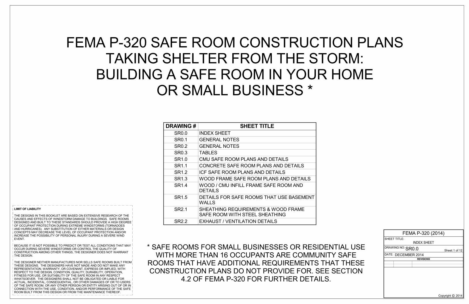
LIMIT OF LIABILITY
THE DESIGNS IN THIS BOOKLET ARE BASED ON EXTENSIVE RESEARCH OF THECAUSES AND EFFECTS OF WINDSTORM DAMAGE TO BUILDINGS. SAFE ROOMSDESIGNED AND BUILT TO THESE STANDARDS SHOULD PROVIDE A HIGH DEGREEOF OCCUPANT PROTECTION DURING EXTREME WINDSTORMS (TORNADOESAND HURRICANES). ANY SUBSTITUTION OF EITHER MATERIALS OR DESIGNCONCEPTS MAY DECREASE THE LEVEL OF OCCUPANT PROTECTION AND/ORINCREASE THE POSSIBILITY OF PERSONAL INJURY DURING A SEVERE WINDEVENT.
BECAUSE IT IS NOT POSSIBLE TO PREDICT OR TEST ALL CONDITIONS THAT MAYOCCUR DURING SEVERE WINDSTORMS OR CONTROL THE QUALITY OFCONSTRUCTION AMONG OTHER THINGS, THE DESIGNER DOES NOT WARRANTTHE DESIGN.
THE DESIGNER NEITHER MANUFACTURES NOR SELLS SAFE ROOMS BUILT FROMTHESE DESIGNS. THE DESIGNERS HAVE NOT MADE AND DO NOT MAKE ANYREPRESENTATION, WARRANTY, OR COVENANT, EXPRESS OR IMPLIED, WITHRESPECT TO THE DESIGN, CONDITION, QUALITY, DURABILITY, OPERATION,FITNESS FOR USE, OR SUITABILITY OF THE SAFE ROOM IN ANY RESPECTWHATSOEVER. THE DESIGNERS SHALL NOT BE OBLIGATED OR LIABLE FORACTUAL, INCIDENTAL, CONSEQUENTIAL, OR OTHER DAMAGES OF OR TO USERSOF THE SAFE ROOM, OR ANY OTHER PERSON OR ENTITY ARISING OUT OF OR INCONNECTION WITH THE USE, CONDITION, AND/OR PERFORMANCE OF THE SAFEROOM BUILT FROM THIS DESIGN OR FROM THE MAINTENANCE THEREOF.
Copyright 2014
SHEET TITLE:
©
DRAWING NO:
DATE:of 12Sheet:
FEMA P-320 (2014)
SR0.0INDEX SHEET
DECEMBER 20141
FEMA P-320 SAFE ROOM CONSTRUCTION PLANSTAKING SHELTER FROM THE STORM:
BUILDING A SAFE ROOM IN YOUR HOMEOR SMALL BUSINESS *
DRAWING # SHEET TITLESR0.0 INDEX SHEETSR0.1 GENERAL NOTESSR0.2 GENERAL NOTESSR0.3 TABLESSR1.0 CMU SAFE ROOM PLANS AND DETAILSSR1.1 CONCRETE SAFE ROOM PLANS AND DETAILSSR1.2 ICF SAFE ROOM PLANS AND DETAILSSR1.3 WOOD FRAME SAFE ROOM PLANS AND DETAILSSR1.4 WOOD / CMU INFILL FRAME SAFE ROOM AND
DETAILSSR1.5 DETAILS FOR SAFE ROOMS THAT USE BASEMENT
WALLSSR2.1 SHEATHING REQUIREMENTS & WOOD FRAME
SAFE ROOM WITH STEEL SHEATHINGSR2.2 EXHAUST / VENTILATION DETAILS
REVISIONS
* SAFE ROOMS FOR SMALL BUSINESSES OR RESIDENTIAL USEWITH MORE THAN 16 OCCUPANTS ARE COMMUNITY SAFE
ROOMS THAT HAVE ADDITIONAL REQUIREMENTS THAT THESECONSTRUCTION PLANS DO NOT PROVIDE FOR. SEE SECTION
4.2 OF FEMA P-320 FOR FURTHER DETAILS.

Copyright 2014
SHEET TITLE:
©
DRAWING NO:
DATE:of 12Sheet:
FEMA P-320 (2014)
SR0.1
GENERAL NOTES
DECEMBER 20142
GENERAL NOTES
1. THE CONSTRUCTION DRAWINGS REPRESENT THE FINISHED STRUCTURE. THEY DO NOT INCLUDECONSTRUCTION MEANS AND METHODS. CONTRACTOR SHALL PROVIDE ALL MEASURESNECESSARY TO PROTECT THE STRUCTURE DURING CONSTRUCTION. SUCH MEASURES SHALLINCLUDE BUT ARE NOT LIMITED TO BRACING, SHORING FOR CONSTRUCTION LOADS, TEMPORARYSTRUCTURES, AND PARTIALLY COMPLETED WORK.
2. IF THERE IS A CONFLICT AMONG THE GENERAL NOTES, SPECIFICATIONS, AND PLANS, THE MORESTRINGENT CRITERIA SHALL APPLY.
3. THE CONTRACTOR SHALL BE RESPONSIBLE FOR ALL EXCAVATION PROCEDURES INCLUDINGSHORING AND PROTECTION OF ADJACENT PROPERTY, STRUCTURES, STREETS, AND UTILITIES INACCORDANCE WITH THE LOCAL BUILDING DEPARTMENT. ALL WORK OR CONSTRUCTION SHALLCOMPLY WITH ALL APPLICABLE BUILDING CODES, REGULATIONS, AND SAFETY REQUIREMENTS.
4. THE CONTRACTOR SHALL BE RESPONSIBLE FOR VERIFICATION AND COORDINATION OF ALLDIMENSIONS, CONDITIONS AND ELEVATIONS.
5. OPTIONS ARE FOR CONTRACTORS CONVENIENCE. IF AN OPTION IS USED, THE CONTRACTORSHALL BE RESPONSIBLE FOR ALL NECESSARY CHANGES AND SHALL COORDINATE ALL DETAILS.
6. DETAILS AND NOTES SHALL APPLY, THOUGH NOT NECESSARILY AT A SPECIFIC LOCATION ONPLANS. WHERE NO DETAILS ARE SHOWN, CONSTRUCTION SHALL CONFORM TO SIMILAR WORKON THE PROJECT. DETAILS MAY ONLY SHOW ONE SIDE OF CONNECTION OR MAY OMITINFORMATION FOR CLARITY. WHERE DISCREPANCIES OCCUR IN THESE DRAWINGS, NOTES ANDDETAILS ON DRAWINGS SHALL TAKE PRECEDENCE OVER GENERAL STRUCTURAL NOTES ANDTYPICAL DETAILS.
7. NOT ALL OPENINGS ARE SHOWN IN THESE DRAWINGS. ESTABLISH AND VERIFY ALL OPENINGSAND INSERTS FOR MECHANICAL, PLUMBING, AND ELECTRICAL WITH APPROPRIATE TRADES,DRAWINGS, AND SUBCONTRACTORS PRIOR TO CONSTRUCTION. OPENINGS MAY REQUIREADDITIONAL REINFORCING OR SUPPORTS AS SHOWN ON TYPICAL DETAILS. OPENINGS NEED TOBE PROTECTED PER ICC 500 SECTIONS 310.1 AND 306.3.
8. COMPLETE INSPECTION REQUIREMENTS SHALL BE AS DIRECTED BY THE LOCAL BUILDINGDEPARTMENT.
9. THE CONSTRUCTION DRAWINGS SHOULD NOT BE SCALED. DIMENSIONS APPLY.10. FOLLOW MANUFACTURER’S RECOMMENDATIONS FOR INSTALLING OF UPLIFT/SHEAR
RESISTANCE CONNECTORS.11. TO ENSURE THE SAFE ROOM PROVIDES THE DESIRED LEVEL OF PROTECTION, A PROFESSIONAL
ENGINEER OR ARCHITECT SHOULD BE CONSULTED FOR ANY DESIGN CONDITION FOUND TO BEDIFFERENT FROM THOSE REPRESENTED BY THESE PLANS.
12. TO OBTAIN AN EQUIVALENT LEVEL OF PROTECTION, SAFE ROOM DESIGNS NOT MEETING THESPECIFIC REQUIREMENTS OF THE DESIGNS IN THESE PLANS SHOULD BE DESIGNED TO MEETTHE FEMA SAFE ROOM CRITERIA SET FORTH IN THE 2015 FEMA P-361 “DESIGN ANDCONSTRUCTION GUIDANCE FOR COMMUNITY SAFE ROOMS.”
13. FOR ALL CONSTRUCTION, USE ONLY SCREWS AND HARDWARE THAT HAVE BEEN EVALUATEDTHROUGH AN ANSI-APPROVED PRODUCT CERTIFICATION BODY SUCH AS IAPMO-OES OR ICC-ES.
14. VENTILATION IS TO BE PROVIDED PER PLAN DETAILS. VERIFY SIZE REQUIREMENTS BASED ONSAFE ROOM SIZE AND ICC 500.
15. MAXIMUM WALL HEIGHT FOR SAFE ROOM SHALL BE 8’-0”.16. REFER TO LOCALLY ADOPTED BUILDING CODE FOR EXTERIOR SAFE ROOM WEATHER
PROTECTION REQUIREMENTS.17. FOR COMMUNITY SAFE ROOMS SEE 2014 ICC 500 AND 2015 FEMA P-361 FOR ADDITIONAL DESIGN
REQUIREMENTS.
CONCRETE NOTES
1. REINFORCING BAR DETAILING, FABRICATING, AND PLACING SHALL CONFORM TO THE "ACISTANDARD: DETAILS AND DETAILING OF CONCRETE REINFORCEMENT" (ACI 315) AND THE"MANUAL OF ENGINEERING AND PLACING DRAWINGS FOR REINFORCED CONCRETESTRUCTURES" (ACI 315R) BY THE AMERICAN CONCRETE INSTITUTE. THE MOST CURRENTEDITIONS OF CONCRETE REINFORCING STEEL INSTITUTE'S "REINFORCING BARDETAILING" AND "PLACING REINFORCING BARS" MAY ALSO BE USED.
2. REINFORCING STEEL SHALL CONFORM TO THE REQUIREMENTS OF ASTM A615.REINFORCING SHALL BE GRADE 60 (FY=60 KSI) DEFORMED BARS FOR ALL BARS UNLESSNOTED OTHERWISE ON PLANS OR DETAILS. ALL REINFORCING TO BE WELDED SHALL BEASTM A706, GRADE 60 LOW ALLOY WELDABLE STEEL.
3. WELDING OF REINFORCING BARS, METAL INSERTS, AND CONNECTIONS SHALL CONFORMTO AMERICAN WELDING SOCIETY’S AWS D1.4 – STRUCTURAL WELDING CODE, AND SHALLBE MADE ONLY AT LOCATIONS SHOWN ON PLANS OR DETAILS.
4. ALL REINFORCING SHALL BE BENT COLD. BARS SHALL NOT BE STRAIGHTENED AND RE-BENT. FIELD BENDING OF REBAR SHALL NOT BE ALLOWED UNLESS SPECIFICALLY NOTEDOTHERWISE.
5. REINFORCING BAR SPACING SHOWN ON PLANS ARE AT MAXIMUM ON CENTERS. ALL BARSSHALL BE DETAILED AND PLACED WITHIN 1/2” TOLERANCE IN ANY DIRECTION. SECURELYTIE ALL BARS IN LOCATION BEFORE PLACING CONCRETE.
6. REINFORCING BAR CLEAR COVER REQUIREMENTS:a. CONCRETE PLACED AGAINST EARTH – 3”b. CONCRETE PLACED IN FORMS – 1.5”
7. WELDED WIRE REINFORCING SHALL CONFORM TO THE REQUIREMENTS OF ASTM A1064.LAPS IN WELDED WIRE REINFORCING SHALL BE MADE SUCH THAT THE OVERLAP,MEASURED BETWEEN OUTERMOST CROSS WIRE OF EACH SHEET, IS NOT LESS THAN THESPACING OF CROSS WIRES PLUS 2 INCHES.
8. MECHANICAL SPLICE COUPLERS, FLANGE COUPLERS, THREADED COUPLERS, ETC. SHALLHAVE CURRENT ANSI-APPROVED PRODUCT CERTIFICATION BODY SUCH AS IAPMO-OES ORICC-ES APPROVAL AND SHALL BE CAPABLE OF DEVELOPING 125% OF THE STRENGTH OFTHE BAR.
9. PROVIDE BAR SUPPORTS: BOLSTERS, CHAIRS, SPACERS, AND OTHER DEVICES FORSPACING, SUPPORTING, AND FASTENING REINFORCING BARS AND WELDED WIREREINFORCEMENT IN PLACE. MANUFACTURE BAR SUPPORTS FROM STEEL WIRE, PLASTIC,OR PRECAST CONCRETE ACCORDING TO CRSI's "MANUAL OF STANDARD PRACTICE."
10. PROVIDE TEMPORARY SHORING AND BRACING OF ALL STRUCTURAL AND MISCELLANEOUSELEMENTS UNTIL CONCRETE HAS OBTAINED 80% OF DESIGN STRENGTH.
11. WHEN PLACING CONCRETE IN HOT WEATHER, REFER TO ACI 305R. WHEN PLACINGCONCRETE IN COLD WEATHER, REFER TO ACI 306.1.
12. ALL BELOW GRADE CONSTRUCTION JOINTS SHALL HAVE A CONTINUOUS WATERSTOPCAST INTEGRALLY INTO THE JOINT.
13. WHERE FOOTINGS, WALLS, OR OTHER STRUCTURAL ELEMENTS INTERSECT, CORNER, ORTEE, PROVIDE CORNER BARS WITH REQUIRED LAP LENGTHS TO PROVIDE CONTINUITY OFHORIZONTAL STEEL REINFORCING UNO.
14. PROVIDE MINIMUM 3” COVER FOR ANCHOR BOLTS AND LOCATE HORIZONTALREINFORCEMENT TO THE OUTSIDE FOR ANCHOR BOLT CONTAINMENT UNO.
15. FOLLOW ALL MANUFACTURER’S INSTALLATION RECOMMENDATIONS WHERE DOWELS,BOLTS, OR INSERTS ARE CALLED TO BE ANCHORED TO CAST IN PLACE CONCRETEELEMENTS USING EPOXY ADHESIVES OR MECHANICAL ANCHORAGE.
16. FLY ASH MAY BE USED AS A ONE TO ONE REPLACEMENT UP TO 20% FOR THE TOTALCEMENT CONTENT AS LONG AS THE AMBIENT TEMPERATURE IS ABOVE 50 DEGREESFAHRENHEIT. FLY ASH SHALL BE CLASS C CONFORMING TO ASTM C 618.
17. ALL CONCRETE EXPOSED TO FREEZING SHALL BE AIR ENTRAINED. AIR CONTENT OFFRESH CONCRETE SHALL BE 5-7%.
18. NO LIME SAND FINE AGGREGATE MAY BE USED IN CONCRETE EXPOSED TO WEATHER,VIEW, OR IN HORIZONTAL APPLICATIONS.
19. DO NOT USE AIR ENTRAINED CONCRETE FOR FLOORS WITH A TROWELED FINISH. AT SUCHLOCATIONS ENTRAPPED AIR CONTENT SHALL NOT EXCEED 3%.
20. CONCRETE FOR FOUNDATION WALLS, FOOTINGS, AND INTERIOR SLABS ON GRADE SHALLHAVE A 28-DAY COMPRESSIVE STRENGTH OF 3,000 PSI WITH A SLUMP OF 4" ± 1". THEMAXIMUM WATER TO CEMENT RATIO SHALL BE 0.45 BY WEIGHT.
21. CONCRETE FOR CAST-IN-PLACE WALL SHALL HAVE A 28-DAY COMPRESSIVE STRENGTH OF4,000 PSI WITH A SLUMP OF 4" ± 1". THE MAXIMUM WATER TO CEMENT RATIO SHALL BE 0.45BY WEIGHT.
22. IF ADDITIONAL FLOWABILITY IS REQUIRED FOR PLACEMENT OF ANY CONCRETE MIX, AWATER-REDUCING ADDITIVE CONFORMING TO ASTM C494, TYPE A, D, E, OR F SHALL BEUSED. NO ADDITIONAL WATER MAY BE ADDED TO THE MIX AT THE SITE. SLUMP FORCONCRETE CONTAINING WATER-REDUCING OR HIGH-RANGE WATER-REDUCINGADMIXTURE SHALL NOT EXCEED 8" AFTER ADMIXTURE IS INCORPORATED INTO CONCRETEWITH A 2"-4" SLUMP.
ABBREVIATION LEGEND
AB ANCHOR BOLT ACI AMERICAN CONCRETE INSTITUTE AISC AMERICAN INSTITUTE OF STEEL CONSTRUCTIONAISI AMERICAN IRON AND STEEL INSTITUTE AWS AMERICAN WELDING SOCIETY BO BOTTOM OF BRG BEARING BTM BOTTOMCIP CAST IN PLACE CONCRETE WALLCMU CONCRETE MASONRY UNIT CONC CONCRETE CONN CONNECTION CONT CONTINUOUS DIA DIAMETER DBL DOUBLEEL ELEVATION EQ EQUAL EW EACH WAY FND FOUNDATION FF FINISHED FLOOR FTG FOOTING GA GAGE GYP GYPSUMHORIZ HORIZONTAL ICF INSULATED CONCRETE FORMSINFO INFORMATION KSI KIPS PER SQUARE INCH L LENGTH LB POUNDS LONG LONGITUDINAL MAX MAXIMUM MEP MECHANICAL, ELECTRICAL, PLUMBINGMFR MANUFACTURER MIN MINIMUM MISC MISCELLANEOUS ML MASONRY LINTELMTL METAL NTS NOT TO SCALE OC ON CENTER PCF POUNDS PER CUBIC FOOT PLF POUNDS PER LINEAR FOOT PSF POUNDS PER SQUARE FOOTPSI POUNDS PER SQUARE INCH PT PRESSURE TREATEDRE REFER TO REINF REINFORCING SIM SIMILAR SF SQUARE FOOTSFRM SAFE ROOMSOG SLAB ON GRADESPEC SPECIFICATIONST THICKNESST&B TOP AND BOTTOM TO TOP OF TOC TOP OF CONCRETE ELEVATIONTOF TOP OF FOOTING ELEVATIONTOW TOP OF WALL ELEVATIONTYP TYPICAL UNO UNLESS NOTED OTHERWISEW WIDTHW/ WITHWWR WELDED WIRE REINFORCING
SLAB ON GRADE GENERAL NOTES:
1. 4” (MINIMUM) SLAB ON GRADE REINFORCED WITH WWR 6X6 W2.9XW2.9 (IN SHEETS) OR #4 BARS AT12" OC EACH WAY. LOCATE REINFORCING IN TOP THIRD OF SLAB. PROVIDE BOLSTERS, CHAIRS, OROTHER MEANS APPROVED IN WRITING BY THE ENGINEER TO PROPERLY LOCATE REINFORCING.
2. SLAB ON GRADE INSIDE THE BUILDING STRUCTURE SHALL BE SUPPORTED ON A 6" DRAINAGECOURSE. DRAINAGE COURSE SHALL BE AS FOLLOWS: COURSE OF CLEAN WASHED GRANULARMATERIAL PLACED TO CUT OFF UPWARD CAPILLARY FLOW OF GROUND WATER, OR TO PROVIDE ASTABLE BASE FOR PIPES OR OTHER STRUCTURES. MATERIAL SHALL BE WASHED, EVENLYGRADED MIXTURE OF CLEAN CRUSHED STONE, OR CRUSHED OR UNCRUSHED GRAVEL, ASTM D448, COARSE AGGREGATE GRADING SIZE 57, WITH 100 PERCENT PASSING A 1-1/2 INCH SIEVE ANDNOT MORE THAN 5 PERCENT PASSING A NO. 8 SIEVE.
3. CONSULT WITH LOCAL CODE OFFICIAL FOR VAPOR RETARDER RECOMMENDATIONS.4. PROVIDE JOINT FILLER AT THE INTERFACE OF ALL WALL AND SLAB JOINTS.5. ALL EXPANSIVE CLAYS WITHIN 24” OF FLOOR SLABS SHALL BE REMOVED. ALL FILL BELOW FLOOR
SLABS SHALL BE PROPERLY COMPACTED AND SUBGRADE BROUGHT TO A TRUE AND LEVEL PLANEBEFORE PLACEMENT OF ANY CONCRETE.
REVISIONS

Copyright 2014
SHEET TITLE:
©
DRAWING NO:
DATE:of 12Sheet:
FEMA P-320 (2014)
SR0.2
GENERAL NOTES
DECEMBER 20143
FOUNDATION NOTES
1. ALL FOOTINGS SHALL BEAR ON AND BE FORMED BY CLEAN, UNDISTURBED, VIRGIN,NON-ORGANIC SOIL OR CONTROLLED ENGINEERED FILL WITH A MINIMUM NET BEARINGCAPACITY OF 1500 PSF.
2. EXTERIOR FOOTINGS SHALL BEAR AT OR BELOW MINIMUM BEARING DEPTH PER THELOCAL BUILDING OFFICIAL. MINIMUM BEARING DEPTH IS 30" BELOW ADJACENTFINISHED GRADE.
3. STANDARD PROCEDURES OF FROST PROTECTION FOR FOUNDATIONS ANDEXCAVATIONS SHALL BE EMPLOYED FOR WINTER CONSTRUCTION. BACKFILLING OFEXCAVATIONS SHALL BE DONE AS SOON AS POSSIBLE TO PROTECT FOUNDATIONSFROM FROST.
4. ALL SOIL BELOW SLABS AND FOOTINGS SHALL BE PROPERLY COMPACTED ANDSUBGRADE BROUGHT TO A TRUE AND LEVEL PLANE BEFORE PLACING CONCRETE.
5. FOUNDATION WALLS SHALL HAVE TEMPORARY BRACING BEFORE BACKFILL IS PLACEDAGAINST THEM. TEMPORARY BRACING SHALL NOT BE REMOVED UNTIL WALL ISPERMANENTLY BRACED.
6. FOUNDATION PENETRATIONS SHALL BE SUBJECT TO APPROVAL BY A PROFESSIONALENGINEER OR ARCHITECT. PENETRATIONS SHALL BE THROUGH THE FOUNDATIONSTEMWALL OR WITH A MINIMUM OF 6" COVER BELOW FOOTING.
7. IN AREA OF THE BUILDING, EXISTING ORGANIC MATERIAL, UNSUITABLE SOIL,ABANDONED FOOTINGS, AND ANY OTHER EXISTING UNSUITABLE MATERIALS SHALL BEREMOVED.
8. DRAINAGE FILL SHALL BE A FREE-DRAINING GRANULAR MATERIAL. USE #57 STONE ORAPPROVED EQUAL. REFER TO ASTM D448 FOR GRADATION.
9. EXCAVATION FOR FOOTINGS SHALL BE CUT TO ACCURATE SIZE AND DIMENSIONS ASSHOWN ON PLANS. ALL LOOSE MATERIAL BELOW FOOTINGS SHALL BE REMOVED ANDTHE SURFACE BROUGHT TO A REASONABLE TRUE AND LEVEL PLANE BEFORE PLACINGCONCRETE.
10. WHEN INSTALLATION AND FOUNDATION REQUIREMENTS ARE ADDRESSED BY A LOCALDESIGN PROFESSIONAL, THESE DESIGNS SHALL EXCEED THE DESIGN REQUIREMENTSSET FORTH IN THE ICC-500 FOR RESIDENTIAL SHELTERS FOR BOTH TORNADO ANDHURRICANE HAZARDS.
MASONRY GENERAL NOTES
1. COMPRESSIVE STRENGTH OF CONCRETE MASONRY CONSTRUCTION (CMU) SHALL BE ASFOLLOWS: MASONRY STRENGTH NOT SPECIFICALLY NOTED IN PLAN SHALL BE f’m = 1500PSI MINIMUM.
2. CONCRETE MASONRY SHALL BE HOLLOW LOAD-BEARING CONCRETE MASONRY UNITSCONFORMING TO ASTM C90,. ALL UNITS SHALL BE PLACED IN RUNNING BONDCONSTRUCTION WITH ALL VERTICAL CELLS IN ALIGNMENT EXCEPT AT DRY STACKED INFILLLOCATIONS.
3. MORTAR SHALL CONFORM TO REQUIREMENTS OF TYPE M OR S.4. REINFORCING STEEL SHALL CONFORM TO THE REQUIREMENTS OF ASTM A615.
REINFORCING SHALL BE GRADE 60 (FY=60 KSI) DEFORMED BARS FOR ALL BARS UNLESSNOTED OTHERWISE ON PLANS OR DETAILS. ALL REINFORCING TO BE WELDED SHALL BEASTM A706, GRADE 60 LOW ALLOY WELDABLE STEEL.
5. WELDING OF REINFORCING BARS, METAL INSERTS, AND CONNECTIONS SHALL CONFORMTO AMERICAN WELDING SOCIETY’S AWS D1.4 – STRUCTURAL WELDING CODE, AND SHALLBE MADE ONLY AT LOCATIONS SHOWN ON PLANS OR DETAILS.
6. ALL REINFORCING SHALL BE BENT COLD. BARS SHALL NOT BE STRAIGHTENED AND RE-BENT. FIELD BENDING OF REBAR SHALL NOT BE ALLOWED UNLESS SPECIFICALLY NOTEDOTHERWISE.
7. REINFORCING BAR SPACING SHOWN ON PLANS ARE AT MAXIMUM ON CENTERS. ALL BARSSHALL BE DETAILED AND PLACED WITHIN 1/2” TOLERANCE PERPENDICULAR TO THE WALLAND WITHIN 2” TOLERANCE PARALLEL TO THE WALL. SUPPORT ALL REINFORCEMENT TOPREVENT DISPLACEMENT CAUSED BY CONSTRUCTION LOADS OR BY PLACEMENT OFGROUT AND MORTAR BEYOND ALLOWABLE TOLERANCES.
8. MASONRY GROUT SHALL BE IN ACCORDANCE WITH ASTM C476. GROUT EXCEPT FOR SELF-CONSOLIDATING GROUT SHALL HAVE A SLUMP BETWEEN 8 AND 11” WHEN MEASURED INACCORDANCE WITH ASTM C143. ALL CELLS IN CONCRETE MASONRY UNITS SHALL BESOLID GROUTED. EXCEPTION: DRY-STACKED MASONRY FOR WOOD-FRAME INFILL OPTION.
9. REFERENCE MASONRY DEVELOPMENT AND SPLICE TABLE FOR REINFORCING BAR LAPLENGTHS IN MASONRY CONSTRUCTION.
10. MINIMUM VERTICAL WALL REINFORCING SHALL BE AS INDICATED IN THE PLANS AND SHALLBE FULL HEIGHT IN CENTER OF GROUTED CELL AT WALL INTERSECTIONS, CORNERS ANDDOOR JAMBS.
11. MINIMUM HORIZONTAL WALL REINFORCING SHALL INCLUDE A BOND BEAM AT THE TOP OFTHE WALL WITH A MINIMUM OF 1 NO.4 BAR CONTINUOUS AROUND PERIMETER FOR 6”MASONRY WALLS AND 1 NO. 5 CONTINUOUS AROUND THE PERIMETER FOR 8” MASONRYWALLS. PROVIDE BENT BARS PER TYPICAL DETAILS TO MATCH AND LAP WITH HORIZONTALBOND BEAM REINFORCING AT CORNERS AND WALL INTERSECTIONS TO MAINTAINCONTINUITY OF BOND BEAM REINFORCEMENT.
12. MINIMUM MASONRY LINTEL SHALL BE AS INDICATED IN THE PLANS. ALL LINTELREINFORCING SHALL EXTEND 2 FEET PAST JAMBS UNLESS NOTED OTHERWISE ON PLANSOR DETAILS.
13. MASONRY VENEER SHALL BE ATTACHED TO SUPPORTING WALL FRAMING WITH 3/16" DIA.WALL TIES OR DOVETAIL-TYPE METAL TIES OF EQUIVALENT STIFFNESS EMBEDDED INTOHORIZONTAL MORTAR JOINTS. MAXIMUM VERTICAL SPACING OF TIES SHALL BE 16". MAXHORIZONTAL SPACING SHALL BE 24". TIES IN ALTERNATE COURSES SHALL BE STAGGERED.PROVIDE 9 GA. WIRE REINFORCING IN HORIZONTAL MORTAR JOINTS AT 16" O.C. ENGAGE 9GA. WIRE WITH WALL ANCHOR TIES.
14. LOOSE ANGLE BRICK LINTELS SHALL BE SPECIFIED BY OTHERS.15. RETAINING WALLS, BASEMENT WALLS, ETC., SHALL BE ADEQUATELY WATERPROOFED AND
DRAINED AS SPECIFIED BY OTHERS.16. WHERE VERTICAL REINFORCING INTERSECTS HORIZONTAL REINFORCING, BOTH SHALL BE
CONTINUOUS.17. MAXIMUM HEIGHT FOR GROUT POUR SHALL NOT EXCEED 64” UNLESS A CLEANOUT IS
PROVIDED AT THE BOTTOM OF EACH CELL CONTAINING REINFORCEMENT OR AT AMAXIMUM HORIZONTAL SPACING OF 32” WHICHEVER IS LESS.
18. FOLLOW ALL MANUFACTURER’S INSTALLATION RECOMMENDATIONS WHERE DOWELS,BOLTS, OR INSERTS ARE CALLED TO BE ANCHORED TO CAST IN PLACE CONCRETEELEMENTS USING EPOXY ADHESIVES OR MECHANICAL ANCHORAGE.
GENERAL WOOD FRAMING NOTES
1. WOOD FRAMING LUMBER TO HAVE MODULUS OF ELASTICITY = 1,200,000 PSI MIN.AND Fb = 850 PSI. MIN. FOR NORMAL DURATION LOADING. EXAMPLES OFACCEPTABLE GRADE AND SPECIES OF FRAMING LUMBER INCLUDE #2 ANDBETTER SOUTHERN PINE, DOUGLAS FIR, HEM-FIR, AND SPRUCE-PINE-FIR.
2. PLYWOOD SHOULD BE RATED SHEATHING SPAN RATING 32/16, MIN. 23/32THICKNESS.
3. NAILS SHALL BE COMMON WIRE NAILS AS SPECIFIED ON THE PLANS.4. FOLLOW MANUFACTURER’S RECOMMENDATIONS FOR INSTALLATION OF
UPLIFT/SHEAR RESISTANCE CONNECTORS.5. ALL PLYWOOD JOINTS SHOULD BE SOLIDLY BLOCKED w/ 2x6.6. WALL AND CEILING PENETRATIONS THROUGH THE MISSILE PROTECTION
SHEATHING SHALL BE MINIMIZED.7. DO NOT DRILL THROUGH WALL STUDS OR TOP AND BOTTOM PLATES FOR MEP
SUPPLY LINES OR VENTS. INSTALL MEP SUPPLY LINES AND VENTS IN PLUMBINGCHASE.
8. ALL WOOD FRAMING SHALL BE FREE OF LARGE KNOTS, WARPS, SPLITS, ORDEFECTS.
9. WHERE CALLED FOR ON THE PLANS TO USE FRAMING ANCHORS USE GALVANIZEDOR CORROSION-RESISTANT EQUIVALENT STEEL FRAMING ANCHORS.
10. ALL LUMBER IN CONTACT WITH CONCRETE OR MASONRY SHALL BE TREATED ANDSHALL COMPLY WITH APPLICABLE REQUIREMENTS OF AWPA STANDARD U1, USECATEGORY UC3B.
11. AT OPENINGS PROVIDE FOUR (4) 2X TRIMMER STUDS AT EACH SIDE OF OPENING.12. SHEATHING MAY BE INSTALLED ON INSIDE OR OUTSIDE FACE. SINGLE LAYER TO
BE INSTALLED ON OPPOSITE FACE.
COLD-FORM (LIGHT GAUGE) SHEATHING NOTES
1. YIELD STRENGTH FOR METAL IS 36 KSI MINIMUM2. IN HURRICANE-PRONE REGIONS, ALL METAL SHOULD BE G60 GALVANIZED BY THE
MANUFACTURER.3. SAFE ROOM W/ STEEL SHEATHING COVERED W/ GYP. BOARD FINISH OR OTHERWISE
SEPARATED FROM CONTACT BY SAFE ROOM OCCUPANTS NEED NOT BE GROUNDED.4. SAFE ROOM W/ STEEL SHEATHING UNCOVERED AND AVAILABLE FOR CONTACT BY
SAFE ROOM OCCUPANTS MUST BE GROUNDED AT A SINGLE LOCATION W/ COPPERWIRE AND GROUND ROD TO MEET NATIONAL ELECTRIC CODE AND LOCALREQUIREMENTS.
DESIGN CRITERIA FEMA P-320
1. DESIGN CODES IRC 2012 / IBC 2012 / FEMA P-361 3RD,2015 /ICC 500-2014· RISK CATEGORY IV
2. GRAVITY LOADS
A. TYPICAL ROOF DEAD LOAD SELF WEIGHTCOLLATERAL LOAD 5 PSF
B. LIVE LOADSTYPICAL ROOF LIVE LOAD (LR) 100 PSF MIN
C. ROOF SNOW LOAD- CONSULT LOCAL PROFESSIONAL ENGINEER FOR THE DESIGN OF SNOW
LOADS WHEN SNOW LOADS COULD EXCEED THE SPECIFIED ROOF LIVE LOAD.
3. LATERAL LOADS
A. WIND LOADSWIND SPEED 250 MPHWIND IMPORTANCE FACTOR (I) 1.0EXPOSURE CATEGORY CDIRECTIONALITY FACTOR (Kd) 1.0TOPOGRAPHIC FACTOR (Kzt) 1.0INTERNAL PRESSURE (GCpi) ±0.55
B. SEISMIC LOADS- IN AREAS OF HIGH OR MODERATE SEISMIC DESIGN, CONSULT A LOCAL DESIGN
PROFESSIONAL. SEE SECTION 4.2 OF P-320 FOR MORE INFORMATION.
4. MISSILE IMPACT CRITERIA· VERTICAL SURFACES 15 POUND 2x4 AT 100MPH· HORIZONTAL SURFACES 15 POUND 2x4 AT 67MPH
DOOR NOTES
1. THE SELECTED DOOR SHALL MEET THE DESIGN CRITERIA OF 2015 FEMA P-361AND 2014 ICC-500. ALL DOORS SHALL BE A TESTED ASSEMBLY AND INSTALLEDPER MANUFACTURES RECOMMENDATIONS.
2. FOR WOOD FRAMED SAFE ROOM, DOOR MUST BE PLACED ON LONGEST WALL.3. FOR SMALL BUSINESS APPLICATIONS, DOORS ARE REQUIRED TO BE ADA
ACCESSIBLE WITH A MINIMUM WIDTH OF 3’-0”.
INSULATED CONCRETE FORMS GENERAL NOTES
1. ICF SYSTEM UTILIZED SHALL BE FLAT PANEL SYSTEM PROVIDING CONSISTENT WALLTHICKNESS ACROSS THE ENTIRE WALL. DO NOT USE WAFFLE, SCREEN, POST AND BEAMETC. ICF SYSTEMS.
2. EXTREME CARE SHOULD BE TAKEN WHEN VIBRATING THE CONCRETE INSIDE THEPERMANENT ICF FORMS TO ASSURE CONSOLIDATION OF CONCRETE AND TO ELIMINATEVOIDS IN THE WALL. LIKEWISE, CARE SHOULD BE TAKEN NOT TO OVER-VIBRATECONCRETE THUS SEGREGATING AGGREGATE.
3. REFERENCE ICF MANUFACTURE FOR MAXIMUM POUR HEIGHTS.4. CONCRETE FOR ICF WALLS SHALL HAVE A 28-DAY COMPRESSIVE STRENGTH OF 4,000 PSI
WITH A SLUMP OF 6"+/-1" PER MANUFACTURE RECOMMENDATIONS. THE MAXIMUM WATERTO CEMENT RATIO SHALL BE 0.45 BY WEIGHT.
REVISIONS

LAP SPLICE LENGTHS (INCHES)TENSION (CLASS B SPLICE)
f'c=3000 psiBARSIZE
TOP OTHER TOP OTHER
21 16 21 16 123
23 17 21 16 154
28 21 24 18 195
34 26 29 22 236
52 40 45 34 267
COMPRESSIONf'c=4000 psi f'c=5000 psi 3000, 4000 & 5000 psi
TOP OTHER
21 16
21 16
23 17
26 20
41 31
62 47 54 41 308 49 37
DEVELOPMENT LENGTHS (INCHES)TENSION (CLASS B SPLICE)
f'c=3000 psiBARSIZE
TOP OTHER TOP OTHER
25 17 1915 83
33 22 2619 114
42 28 3224 145
50 33 3929 166
72 48 5642 197
COMPRESSIONf'c=4000 psi f'c=5000 psi 3000, 4000 & 5000 psi
TOP OTHER
13
17
22
26
37
82 55 6447 228 42NOTES:
1. TOP BARS ARE HORIZONTAL REINFORCEMENT PLACED SO THAT MORE THAN12" OF FRESH CONCRETE IS CAST BELOW THE REINFORCEMENT.
2. LAP SPLICE LENGTHS ARE BASED ON BARS SPACED AT 4 BAR DIAMETERSOR MORE ON CENTER. NOTIFY ENGINEER IF SPACING IS LESS THAN 4 BARDIAMETERS.
CONCRETE DEVELOPMENT AND SPLICE
22
29
36
43
63
71
MASONRY DEVELOPMENT AND SPLICE LENGTHSTENSION / COMPRESSIONBAR
SIZE
123
154
235
436
6" MASONRY 8" MASONRY
12
20
32
54
CONCRETE
ROOF DESIGN OPTIONSMATERIAL SPAN 8 FT 10 FT 12 FT 14 FT
CONCRETE THICKNESS
REINFORCEMENT
4"
#4 BAR EW AT 10" OC
6"
#5 BAR EW AT 12" OC
6"
#5 BAR EW AT 6" OC
6"
#5 BAR EW AT 6" OC
WOOD JOIST(S) (2) 2x6 AT 12" OC (2) 2x8 AT 12" OC (2) 2x10 AT 12" OC (2) 2x10 AT 12" OC
NOTES:1. WOOD FRAMED SAFE ROOMS CAN ONLY USE WOOD FRAMED ROOF DESIGNS2. WHEN USING WOOD ROOF WITH CONCRETE, CMU, OR ICF WALLS, SHEATHING MUST BE INSTALLED ON INTERIOR OF CEILING AS
SHOWN ON DETAIL 9/SR1.0
≤ ≤ ≤
CONCRETE
FOOTING SCHEDULEWALL TYPE ROOF TYPE FOOTING SIZE REINFORCEMENT
WOOD
CONCRETE
WOOD FRAME WOOD 4'-0" x 1'-6" x CONT (5) #5 BAR x CONT LONG. AND #5 BAR x 3'-6" TRANS AT 12" OC
6" CMU WOOD OR CONCRETE
WOOD / CMU INFILL WOOD
ICFWOOD
CONCRETE
3'-0" x 1'-3" x CONT
2'-3" x 1'-0" x CONT
2'-3" x 1'-3" x CONT
2'-0" x 1'-0" x CONT
2'-3" x 1'-3" x CONT
2'-0" x 1'-0" x CONT
(4) #5 BAR x CONT LONG. AND #5 BAR x 2'-6" TRANS AT 12" OC
(4) #5 BAR x CONT LONG. AND #5 BAR x 1'-9" TRANS AT 12" OC
(4) #5 BAR x CONT LONG. AND #5 BAR x 1'-9" TRANS AT 12" OC
(3) #5 BAR x CONT LONG. AND #5 BAR x 1'-6" TRANS AT 12" OC
(4) #5 BAR x CONT LONG. AND #5 BAR x 1'-9" TRANS AT 12" OC
(3) #5 BAR x CONT LONG. AND #5 BAR x 1'-6" TRANS AT 12" OC
8" CMU WOOD OR CONCRETE 2'-0" x 1'-0" x CONT (3) #5 BAR x CONT LONG. AND #5 BAR x 1'-6" TRANS AT 12" OC
LOCATION
A
REQUIRED UPLIFTCAPACITY (LBS)
SIMPSONSTRONG-TIE
UNITED STEELPRODUCTS
BCDEFGH
8001,8501,5001,500800
1,5001,7001,700
HGA10SSTB16 AND BPS 5/8-6*
2-MTS12HETA16HGAM10
LGT22-SP6
HETA 16 OR PAI23
HGA10
2-MTW12HTA16
HGAM10LUGT22-SPT6
2-HTA12
WOOD CONSTRUCTION CONNECTOR SCHEDULE
NOTES:* THE PLATE WASHER SHALL BE CENTERED ON THE BOTTOMPLATE WITH A STANDARD CUT WASHER BETWEEN THE PLATEWASHER AND NUT. WHEN IN CONTACT WITH PRESERVATIVETREATED PLATE, IT IS RECOMMENDED TO INSTALL HOT-DIPPEDGALVANIZED (HDG) FINISH.** AT TIME OF PUBLICATION, NO EQUIVALENT USP CONNECTORAVAILABLE. PLATE WASHER MAY BE FABRICATED FROM 3 GAGESTEEL: 3" LONG x 4 1/2" WIDE
BECAUSE NOT ALL CONTRACTORS ARE FAMILIAR WITH THE TYPEOF STRUCTURAL CONNECTORS SHOWN IN THESE DRAWINGS,THE NAMES OF TWO COMPANIES THAT MANUFACTURECONNECTORS HAVE BEEN INCLUDED IN THIS TABLE. THE LIST OFCOMPANIES IS NOT, HOWEVER, EXHAUSTIVE. ADDITIONALLY, THISLIST IS NOT INTENDED TO EXPRESS A PREFERENCE FOR THOSEMANUFACTURERS AND / OR THEIR PRODUCTS BY THE UNITEDSTATES GOVERNMENT NOR IS IT AN ENDORSEMENT OF THOSEMANUFACTURERS AND / OR THEIR PRODUCTS.
USE ONLY HARDWARE THAT HAVE BEEN EVALUATED THROUGHAN ANSI-APPROVED PRODUCT CERTIFICATION BODY SUCH ASIAPMO-OES OR ICC-ES.
J 4,500 HDU8-SDS2.5 PHD8
STB16 **
WALL REINFORCEMENT SCHEDULE
WALL TYPEWALL REINFORCEMENT OPENING REINFORCEMENT
NOTES
8" CMU (1) #5 BAR AT 40" OC 2
6" ICF
6" CONCRETE 2
1,2
VERTICAL HORIZONTAL VERTICAL (JAMB) HORIZONTAL (HEADER)
#4 BAR AT 12" OC
#4 BAR AT 12" OC
#4 BAR AT 12" OC
#4 BAR AT 12" OC
REINFORCEMENT PER GENERAL NOTES
(3) #5 BAR AT 6" OC *
(1) #5 BAR PER CELL OVER 2'-0" *
(3) #5 BAR AT 6" OC *
16" BOND BEAM w/ (1) #5 BAR TOP AND BTM
(1) #5 BAR TOP AND BTM
(1) #5 BAR TOP AND BTMNOTES:1. ICF WALL THICKNESS REFERS TO THE CONCRETE THICKNESS OF THE ICF WALL, NOT THE TOTAL THICKNESS OF THE WALL.2. REFERENCE SPLICE TABLE FOR EXTENSION OF HEADER REINFORCEMENT PAST OPENING.3. 6" CMU WALLS CAN ONLY BE USED ON SAFE ROOMS 8'-0"x8'-0" OR SMALLER
4" ICF 1,2#4 BAR AT 12" OC #4 BAR AT 12" OC (3) #5 BAR AT 6" OC * (1) #5 BAR TOP AND BTM
6" CMU (1) #5 BAR AT 16" OC 3REINFORCEMENT PER GENERAL NOTES (1) #5 BAR PER CELL OVER 2'-0" * 16" BOND BEAM w/ (1) #5 BAR TOP AND BTM
* AT 1'-4" WALL END, THIRD BAR MAY BE SET IN ADJACENT WALL
Copyright 2014
SHEET TITLE:
©
DRAWING NO:
DATE:of 12Sheet:
FEMA P-320 (2014)
SR0.3
TABLES
DECEMBER 20144
FOOTING SCHEDULE
WALL REINFORCEMENT SCHEDULE1
WOOD CONSTRUCTION CONNECTOR SCHEDULE
ROOF DESIGN OPTIONS
MASONRY DEVELOPMENT & SPLICE LENGTHSCONCRETE DEVELOPMENT AND SPLICE TABLE
REVISIONS
SR0.3
3SR0.3
2SR0.3
4SR0.3
5SR0.3
6SR0.3

14' - 0" MAX
8' - 0" MIN
14' -
0" M
AX
8' -
0" M
IN
(TY
P)
5 5/
8" O
R
7 5/
8" C
MU
3SR1.0
(TYP)
5 5/8" OR 7 5/8" CMU
PROVIDE (1) #5 VERTICALBAR AT EVERY CORNERAND ADJACENT CELL,TYP
SEE SCHEDULE 1/SR0.3FOR REINFREQUIREMENTS
GROUT ALLCELLS SOLID,
TYP
FOR
JA
MB
REI
NF
SE
E SC
HE
DU
LE 1
/SR
0.3
FOOTING BELOW
1' -
4"3'
- 4"
FINISH FLOOR0' - 0"
TO WALL8' - 0"
SR1.05 SR1.0
4
SR1.07SR1.0
8
MAX
REINFORCEMENT NOTSHOWN FOR CLARITY
14' - 0" MAX
8' - 0" MIN
14' -
0" M
AX
8' -
0" M
IN
SAFE ROOMDOOR BYOTHERS
DOOR CONNECTIONREQUIREMENTS INACCORDANCE w/DOOR MANUFACTURE
REINFORCEMENT NOTSHOWN FOR CLARITY
TO SLAB
#5 BAR CONTINUOUS
CONCRETE SLAB ON GRADEPER GENERAL NOTES
FINISH GRADE
GROUT ALL CELLSSOLID
1/2" CONCRETE ISOLATION JOINT
8"
TO FOOTING
#5 VERT BARS AT EACH VERTBAR LOCATION, ALTERNATE
DIRECTION OF EVERY OTHERBENT BAR
.
.
CONTINUOUSREINFORCEMENT IN SAFEROOM WALLS, PER PLAN
CLR3"
SEE SCHEDULE 2/SR0.3FOR FOOTING SIZE ANDREINFORCING
PE
R C
OD
E
MIN
FR
OST
DE
PTH
#4 DOWEL AT 24" OC
TO SLAB
#5 BAR CONTINUOUSCONCRETE SOGPER GENERAL NOTES
CMU WALLSEE PLAN
FINISH GRADE
8"
CMU WALL BEYOND
BOND BEAM W/ (1) #5CONT. (USE #4 BAR IF
USING 6" MASONRY UNITS)
TO FOOTING
GROUT ALL CELLSBELOW GRADE SOLID
#5 VERT BARS AT EACHVERT BAR LOCATION,ALTERNATE DIRECTIONOF EVERY OTHER BENTBAR.
.
CONTINUOUSREINFORCEMENT INSAFE ROOM WALLS,
PER PLAN
CLR3"SEE SCHEDULE 2/SR0.3 FOR
FOOTING SIZE AND REINFORCING
PE
R C
OD
E
MIN
FR
OST
DE
PTH
#4 DOWEL AT 24" OC
SEE SCHEDULE 2/SR0.3FOR FOOTING SIZE ANDREINFORCING
.
CONCRETE SLAB ON GRADEPER GENERAL NOTES
CONTINUOUSREINFORCEMENT IN SAFEROOM WALLS, PER PLAN
3" C
LR T
YP
.
#5 VERT BARS AT EACH VERTBAR LOCATION, ALTERNATE
DIRECTION OF EVERY OTHERBENT BAR
TO SLAB
8" 8"
CONCRETE ROOF, SEESCHEDULE 3/SR0.3 FOR
THICKNESS & REINFORCING
#4 BAR AT 16" OC (SEE GENERALNOTES FOR SPLICE LENGTHS) MIN.
TURN DOWN INTO WALL IS 24"(LONG) FROM BOTTOM OF SLAB
CMU WALL PER PLAN
BOND BEAM PER GENERAL NOTES#4 BAR AT 16" OC (SEE GENERALNOTES FOR SPLICE LENGTHS)MIN. TURN DOWN INTO WALL IS14" (LONG) FROM BOTTOM OFSLAB
CONCRETE ROOF, SEESCHEDULE 3/SR0.3 FORTHICKNESS & REINFORCING
16" BOND BEAM w/ (1) #5 BAR TOPAND BOTTOM (USE #4 BAR IFUSING 6" MASONRY UNITS)
BOND BEAM w/ (1) #5(USE #4 BAR IF USING 6"
MASONRY UNITS)
CMU, ICF OR CONCRETEWALL PER PLAN
CONNECTOR "D" SEESCHEDULE 4/SR0.3
CEILING PER DETAIL 8SHEET SR1.3
CEILING JOIST, SEESCHEDULE 3/SR0.3 FORSIZING AND SPACING
DO NOT ATTACH SHELTERCEILING TO FLOOR ORCEILING ABOVE
CONNECTOR "E" TYP,SEE SCHEDULE 4/SR0.3
2xPT RIM BOARD
NOTE:1. FINISHED FLOOR ELEVATION SHALL BE
LESS THAN 5 FT ABOVE LOWESTFINISHED ADJACENT GRADE ELEVATION
2. SEE SR0.3 FOR SCHEDULES
1' - 0" 4' - 0"
3" C
LR
3" CLR
STANDARD 90 DEGHOOK, TYP
#5 NOSING BAR, TYP#5 DOWEL AT 12" OCCENTERLINE OF STEP
DOWELS TO MATCHFOOTING REINF SIZE
AND QUANTITY
LAPSPLICE
LAPSPLICE AS
REQ'D
NOTE: SPLICE TOP REINFORCING THE SAME AS BOTTOM WHERE TOP ANDBOTTOM REINFORCING IS INDICATED. SEE SCHEDULE 6/SR0.3
3" C
LR
3" M
IN.
TO FOOTING
TO FOOTING
SEE SCHEDULE 2/SR0.3 FOR SIZE AND REINFORCING
3" CLR
SEE SCHEDULE2/SR0.3 FOR SIZE AND
REINFORCING
NOTE
NOTE
Copyright 2014
SHEET TITLE:
©
DRAWING NO:
DATE:of 12Sheet:
FEMA P-320 (2014)
SR1.0
CMU SAFE ROOM PLANS AND DETAILS
DECEMBER 20145
SR1.0 Scale: 1/4" = 1'-0"CMU FOUNDATION PLAN1
SR1.0 Scale: 1/4" = 1'-0"CMU CROSS SECTION3
SR1.0 Scale: 1/4" = 1'-0"CMU FLOOR PLAN2
SR1.0 Scale: 1/2" = 1'-0"
CMU EXTERIOR WALL FOUNDATION4SR1.0 Scale: 1/2" = 1'-0"
CMU EXTERIOR WALL FOUNDATION AT DOOR5SR1.0 Scale: 1/2" = 1'-0"
ALT CMU INTERIOR WALL THICKENED SLAB6
SR1.0 Scale: 1/2" = 1'-0"CMU SECTION AT TOP7
SR1.0 Scale: 1/2" = 1'-0"CMU SECTION AT DOOR BEAM8
SR1.0 Scale: 1/2" = 1'-0"ALT WALL/CEILING CONNECTION9
SR1.0 Scale: 1/2" = 1'-0"TYPICAL FOOTING STEP10
REVISIONS

3SR1.1
14' - 0" MAX
8' - 0" MIN
14' -
0" M
AX
8' -
0" M
IN
1' -
4"3'
- 4"
SEE SCHEDULE 1/SR0.3FOR REINF REQUIREMENTS
SR1.19
FOOTING BELOW
FOR
JAM
B R
EIN
FS
EE
SCH
ED
ULE
1/S
R0.
3
6" TYP
14' - 0" MAX
8' - 0" MIN
14' -
0" M
AX
8' -
0" M
IN
SAFE ROOM DOOR BYOTHERSDOOR CONNECTIONREQUIREMENTS INACCORDANCE w/ DOORMANUFACTURE
REINFORCEMENT NOTSHOWN FOR CLARITY
FINISH FLOOR0' - 0"
TO WALL8' - 0"
SR1.14
SR1.15
SR1.18
SR1.17
CIP WALLPER PLAN
REINFORCEMENT NOTSHOWN FOR CLARITY
REINFORCEMENT NOTSHOWN FOR CLARITY
MAX
TO SLAB
CONCRETE SLAB ON GRADE PERGENERAL NOTES
FINISHED GRADE
TO FOOTING
#5 BARS CONT1/2" CONCRETE ISOLATION JOINT
CIP WALL PERPLAN
.
MIN
3" T
YP
.
#5 BARS AT EACH VERT LOCATION,ALTERNATE DIRECTION OF EVERY
OTHER BENT BAR
SEE SCHEDULE 2/SR0.3 FORFOOTING SIZE AND REINFORCING
PE
R C
OD
E
MIN
FR
OST
DE
PTH
CONT REINF IN SAFE ROOMWALL PER PLAN
#4 DOWEL AT 24" OC
8"
TO SLABFINISHED GRADE
TO FOOTING
.
PE
R C
OD
E
MIN
FR
OST
DE
PTH
MIN
3" T
YP
#5 BARS CONT
CIP WALL PERPLAN
.
WALL BEYONDCONCRETE SLAB ON GRADE PERGENERAL NOTES
#5 BARS AT EACH VERT LOCATION,ALTERNATE DIRECTION OF EVERYOTHER BENT BAR
SEE SCHEDULE 2/SR0.3FOR FOOTING SIZE ANDREINFORCING
CONT REINF IN SAFE ROOMWALL PER PLAN
#4 DOWEL AT 24" OC
8"
CIP WALL PERPLAN
SEE SCHEDULE2/SR0.3 FOR FOOTINGSIZE ANDREINFORCING
.
CONCRETE SLAB ON GRADEPER GENERAL NOTES
3" C
LR T
YP
.
TO SLAB
8" 8"
#4 BAR AT 16" OC (SEE GENERALNOTES FOR SPLICE LENGTHS) MIN.
TURN DOWN INTO WALL IS 24"(LONG) FROM BOTTOM OF SLAB
CIP WALLPER PLAN
VA
RIE
S
CONCRETE ROOF, SEE SCHEDULE3/SR0.3 FOR THICKNESS &
REINFORCING. SEE 9/SR1.0 FOR ALTWOOD ROOF CONNECTION
#4 BAR AT 16" OC (SEE GENERALNOTES FOR SPLICE LENGTHS) MIN.TURN DOWN INTO WALL IS 14"(LONG) FROM BOTTOM OF SLAB
VA
RIE
S1'
- 4"
MIN
CIP WALLPER PLAN
CONCRETE ROOF, SEE SCHEUDLE3/SR0.3 FOR THICKNESS &REINFORCING. SEE 9/SR1.0 FOR ALTWOOD ROOF CONNECTION
LAP SPLICE PERTABLE ONCONCRETE OPTION
CIP WALL PER PLAN
NOTE:1. FINISHED FLOOR ELEVATION SHALL BE
LESS THAN 5 FT ABOVE LOWESTFINISHED ADJACENT GRADE ELEVATION
2. SEE SR0.3 FOR SCHEDULES
Copyright 2014
SHEET TITLE:
©
DRAWING NO:
DATE:of 12Sheet:
FEMA P-320 (2014)
SR1.1
CONCRETE SAFE ROOM PLANS AND DETAILS
DECEMBER 20146
SR1.1 Scale: 1/4" = 1'-0"CONCRETE FOUNDATION PLAN1
SR1.1 Scale: 1/4" = 1'-0"CONCRETE FLOOR PLAN2
SR1.1 Scale: 1/4" = 1'-0"CONCRETE CROSS SECTION3
SR1.1 Scale: 1/2" = 1'-0"
CONC EXTERIOR WALL FOUNDATION4SR1.1 Scale: 1/2" = 1'-0"
CONC EXTERIOR WALL FOUNDATION AT DOOR5SR1.1 Scale: 1/2" = 1'-0"
ALT CONC INTERIOR WALL THICKENED SLAB6
SR1.1 Scale: 1/2" = 1'-0"CONC SECTION AT TOP7
SR1.1 Scale: 1/2" = 1'-0"CONC SECTION AT DOOR BEAM8
SR1.1 Scale: 1/2" = 1'-0"CONC SECTION AT CORNER9
REVISIONS

14' -
0" M
AX
8' -
0" M
IN
14' - 0" MAX
8' - 0" MIN
3SR1.2
SR1.29
SEE SCHEDULE 1/SR0.3FOR REINF REQUIREMENTS
FOOTING BELOW
1' -
4"3'
- 4"
FOR
JAM
B R
EIN
FS
EE
SCH
ED
ULE
1/S
R0.
3
SEE 9/SR1.24" OR 6" TYP
14' -
0" M
AX
8' -
0" M
IN
SAFE ROOM DOOR BYOTHERS
14' - 0" MAX
8' - 0" MIN
DOOR CONNECTIONREQUIREMENTS INACCORDANCE w/ DOORMANUFACTURE
REINFORCEMENT NOTSHOWN FOR CLARITY
FINISH FLOOR0' - 0"
TO WALL8' - 0"
ICF WALL PER PLAN
SR1.25
SR1.24
SR1.27
SR1.28
REINFORCEMENT NOTSHOWN FOR CLARITY
REINFORCEMENT NOTSHOWN FOR CLARITY
MAX
TO SLAB FINISHED GRADE
TO FOOTING
#5 BARS CONT1/2" CONCRETE ISOLATION JOINT ICF WALL PER
PLAN
.
MIN
3" T
YP
.
PE
R C
OD
E
MIN
FR
OST
DE
PTH
CONCRETE SLAB ON GRADE PERGENERAL NOTES
CONT REINF IN SAFE ROOMWALL PER PLAN
#5 BARS AT EACH VERT LOCATION,ALTERNATE DIRECTION OF EVERY
OTHER BENT BAR
SEE SCHEDULE 2/SR0.3 FORFOOTING SIZE AND REINFORCING
#4 DOWEL AT 24" OC
8"
TO SLABCONCRETE SLAB ON GRADE PERGENERAL NOTESFINISHED GRADE
CONT REINF IN SAFE ROOM WALL PER PLAN
TO FOOTING
.
PE
R C
OD
E
MIN
FR
OST
DE
PTH
MIN
3" T
YP
#5 BARS CONT
ICF WALL PERPLAN
.
#5 BARS AT EACH VERT LOCATION, ALTERNATEDIRECTION OF EVERY OTHER BENT BAR
SEE SCHEDULE 2/SR0.3FOR FOOTING SIZE ANDREINFORCING
WALL BEYOND #4 DOWEL AT 24" OC
8"
#4 BAR AT 16" OC (SEE GENERALNOTES FOR SPLICE LENGTHS) MIN.
TURN DOWN INTO WALL IS 24"(LONG) FROM BOTTOM OF SLAB
ICF WALL PERPLAN
VA
RIE
S
CONCRETE ROOF, SEE SCHEDULE3/SR0.3 FOR THICKNESS &
REINFORCING.SEE 9/SR1.0 FORALT WOOD ROOF CONNECTION
LAP SPLICE PERTABLE ONCONCRETE OPTION
ICF WALL PER PLAN
THICKNESS
SEE SCHEDULE 1/SR0.3ON SR0.3 FOR CONC
#4 BAR AT 16" OC (SEE GENERALNOTES FOR SPLICE LENGTHS) MIN.TURN DOWN INTO WALL IS 14"(LONG) FROM BOTTOM OF SLAB
VA
RIE
S
ICF WALL PERPLAN
1' -
4"
CONCRETE ROOF, SEE SCHEUDLE3/SR0.3 FOR THICKNESS &REINFORCING. SEE 9/SR1.0 FORALT WOOD ROOF CONNECTION
SEE SCHEDULE 2/SR0.3FOR FOOTING SIZE ANDREINFORCING
.
CONCRETE SLAB ON GRADEPER GENERAL NOTES
3" C
LR T
YP
.
TO SLAB
ICF WALL PERPLAN
CONT REINF IN SAFE ROOMWALL PER PLAN#5 BARS AT EACH VERTLOCATION, ALTERNATEDIRECTION OF EVERY OTHERBENT BAR
8" 8"
NOTE:1. FINISHED FLOOR ELEVATION SHALL BE
LESS THAN 5 FT ABOVE LOWESTFINISHED ADJACENT GRADE ELEVATION
2. SEE SR0.3 FOR SCHEDULES
Copyright 2014
SHEET TITLE:
©
DRAWING NO:
DATE:of 12Sheet:
FEMA P-320 (2014)
SR1.2
ICF SAFE ROOM PLANS AND DETAILS
DECEMBER 20147
SR1.2 Scale: 1/4" = 1'-0"ICF FOUNDATION PLAN1
SR1.2 Scale: 1/4" = 1'-0"ICF FLOOR PLAN2
SR1.2 Scale: 1/4" = 1'-0"ICF CROSS SECTION3
SR1.2 Scale: 1/2" = 1'-0"ICF EXTERIOR WALL FOUNDATION4
SR1.2 Scale: 1/2" = 1'-0"ICF EXTERIOR WALL FOUNDATION AT DOOR5
SR1.2 Scale: 1/2" = 1'-0"ICF SECTION AT TOP7
SR1.2 Scale: 1/2" = 1'-0"ICF CORNER DETAIL9
SR1.2 Scale: 1/2" = 1'-0"ICF SECTION AT DOOR BEAM8
SR1.2 Scale: 1/2" = 1'-0"ALT ICF INTERIOR WALL THICKENED SLAB6
REVISIONS

14' -
0" M
AX
8' -
0" M
IN
3SR1.3
14' - 0" MAX
8' - 0" MIN
SR1.36
SR1.37
(4) 2x6 STUDSEACH SIDE OFDOOR
1' -
0"
3' -
4"
FOOTING BELOW
14' -
0" M
AX
8' -
0" M
IN
14' - 0" MAX
8' - 0" MINSAFE ROOM DOOR BY OTHERS
LOCATE DOORALONG LONGEST
WALL
DOOR CONNECTIONREQUIREMENTS INACCORDANCE w/ DOORMANUFACTURE
FINISH FLOOR0' - 0"
SR1.34SR1.3
5
SR1.38
BLOCKING ATSHEATHING JOINTLOCATIONS, REFER TOSHEATHINGREQUIREMENTS SHEET
BLOCKING ATQUARTER
POINTS
SR1.48 SIM
REINFORCEMENTNOT SHOWN FORCLARITY
MAX
TO WALL8' - 0"
CONCRETE SLAB ON GRADEPER GENERAL NOTES
FINISHED GRADE
#5 BARS AT 18" OC
#5 BARS CONT
8" CONCRETEWALL
SHEATHING SEE SR2.1
STUD WALL PER PLAN
#5 BARS AT 18" OC, ALTERNATEDIRECTION OF EVERY OTHER BENT BAR
SEE SCHEDULE 2/SR0.3FOR FOOTING SIZE AND
REINFORCING
#4 DOWEL AT 24" OC
SEE WOOD WALL BASE PLANFOR WALL REQUIREMENTS
TO SLAB
TO FOOTING
.
MIN
3" T
YP
.
2' -
6" M
IN
8"
TO SLAB
CONCRETE SLAB ON GRADE PERGENERAL NOTES
FINISHED GRADE
#5 BARS AT 18" OC
TO FOOTING
#5 BARS CONT
8" CONCRETEWALL
.
MIN
3" T
YP
.
#5 BARS AT 18" OC, ALTERNATEDIRECTION OF EVERY OTHER BENT BAR
SEE SCHEDULE 2/SR0.3FOR FOOTING SIZE ANDREINFORCING
2' -
6" M
IN
WALL BEYOND
#4 DOWEL AT 24" OC
8"
DBL 2"x6" STUDS AT12" OC, NAILED AT6" OC, STAGGEREDON EACH SIDE w/16d NAILS
14 GA STEELSHEATHING
CONTINUOUSSEE SR2.1
(2) LAYERS 3/4"PLYWOODSEE SR2.1
STUD TO SILLPLATECONNECTOR "G" (TYP) SEESCHEDULE 4/SR0.3
CONNECTOR "B" TYP AT24" OC AND W/IN 12" OF
DOOR OPENING, SEE4/SR0.3
(1) LAYER 3/4" PLYWOOD
CONNECTOR "A" TYP ATEACH STUD, SEESCHEDULE 4/SR0.3
SEE WOOD WALL BASEPLAN FOR WALLREQUIREMENTS
14 GA STEEL SHEATHINGCONTINUOUS TO INSIDE
CORNER
(2) LAYERS 3/4" PLYWOODCONTINUOUS TO INSIDE
CORNER
DO NOT ATTACH SAFEROOM CEILING TO FLOOR
OR CEILING ABOVEWOOD JOIST, SEE SCHEDULE
3/SR0.3 FOR MEMBER SIZEAND SPACING
DBL 2"x6" TOP PLATE, NOSPLICING PERMITTED
CONNECTOR "F" SEESCHEDULE 4/SR0.3
2x RIM JOISTBLOCKING AT QUARTER
POINTS
CONNECTOR "A" TYP,SEE SCHEDULE 4/SR0.3
SPLICE SECOND LAYEROF SHEATHING HERE IFNEEDED
14 GA STEEL SHEATHINGCONTINUOUS TO INSIDECORNER
(2) LAYERS 3/4" PLYWOODCONTINUOUS TO INSIDECORNER
DO NOT ATTACH SAFE ROOMCEILING TO FLOOR OR CEILING
ABOVE
WOOD JOIST, SEE SCHEDULE3/SR0.3 FOR MEMBER SIZE
AND SPACING
BLOCKING AT QUARTERPOINTS
NOTE:WOOD ROOF WITH EXTERIOR SHEATHING NOT TO BE USED ON CONCRETE, CMU, OR ICF WALL TYPES INTERIOR
OF SAFEROOM
2"x6" NAILER CONNECTEDw/ 16d NAILS AT 12" OC
2"x6" NAILERCONNECTED w/ 16d
NAILS AT 12" OC
QUAD 2"x6" CORNERSTUDS
CONNECTOR B (TYP) AT 24"OC AND W/IN 12" OF DOOROPENING, SEE SCHEDULE4/SR0.3
CONNECTOR "J" SEESCHEDULE 4/SR0.3
CONNECTOR B (TYP)AT 24" OC AND WITHIN
12" OF CONNECTOR"J" AND W/IN 12" OF
DOOR OPENING
NOTE:1. FINISHED FLOOR ELEVATION SHALL BE
LESS THAN 5 FT ABOVE LOWESTFINISHED ADJACENT GRADE ELEVATION
2. SEE SR0.3 FOR SCHEDULES
Copyright 2014
SHEET TITLE:
©
DRAWING NO:
DATE:of 12Sheet:
FEMA P-320 (2014)
SR1.3
WOOD FRAME SAFE ROOM PLANS AND DETAILS
DECEMBER 20148
SR1.3 Scale: 1/4" = 1'-0"WOOD FRAME FOUNDATION PLAN1
SR1.3 Scale: 1/4" = 1'-0"WOOD FLOOR PLAN2
SR1.3 Scale: 1/4" = 1'-0"WOOD CROSS SECTION3
SR1.3 Scale: 1/2" = 1'-0"WOOD EXTERIOR WALL FOUNDATION4
SR1.3 Scale: 1/2" = 1'-0"WOOD EXTERIOR WALL FOUNDATION AT DOOR5
SR1.3 Scale: 3/4" = 1'-0"WOOD WALL BASE PLAN VIEW6
SR1.3 Scale: 3/4" = 1'-0"WOOD CEILING ATTACHMENT8
SR1.3 Scale: 3/4" = 1'-0"WOOD CEILING ALTERNATE (WOOD FRAME SAFE ROOM ONLY)9
SR1.3 Scale: 3/4" = 1'-0"WOOD WALL CORNER PLAN7
REVISIONS

14' -
0" M
AX
8' -
0" M
IN
14' - 0" MAX
8' - 0" MIN
3SR1.4
SR1.49
SR1.46
(4) 2x6 STUDSEACH SIDE OFDOOR
1' -
0"
3' -
4"
FOOTING BELOW
14' -
0" M
AX
8' -
0" M
IN
14' - 0" MAX
8' - 0" MINSAFE ROOM DOOR BYOTHERS
LOCATE DOORALONG LONGEST
WALL
DOOR CONNECTIONREQUIREMENTS INACCORDANCE w/DOOR MANUFACTURE
FINISH FLOOR0' - 0"
SR1.44
SR1.45
SR1.47SR1.4
8
BLOCKING ATQUARTER
POINTS
REINFORCEMENT NOTSHOWN FOR CLARITY
MAX
TO WALL8' - 0"
WALL FINISH
DBL 2"x6" STUDS AT 12" OC,NAILED AT 6" OC, STAGGEREDON EACH SIDE w/ 16d NAILS
(1) LAYER 3/4"PLYWOOD
STUD TO SILLPLATECONNECTOR "G" (TYP)
SEE SCHEDULE 4/SR0.3
CONNECTOR "B" TYP AT24" OC, AND W/IN 12" OF
DOOR OPENINGS, SEESCHEDULE 4/SR0.3
(2) LAYERS 3/4"PLYWOOD SEE S2.1
NOTE:USE EXPANSION FOAM TO FILLALL SPACES AROUND CMU
6" SOLID MASONRYDRY STACKED
VERTICALLY
DBL 2x6 SILL PLATEBELOW BLOCK
1' -
0" O
.C.
1/8" FURRING STRIPATTACH TO FACE OF
DBL 2x6
CONNECTOR "A" TYP, SEESCHEDULE 4/SR0.3
INTERIOROF SAFE
ROOM
2"x6" NAILER CONNECTEDw/ 16d NAILS AT 12" OC
2"x6" NAILERCONNECTED w/ 16d
NAILS AT 12" OC
QUAD 2"x6" CORNERSTUDS
SEE WOOD / CMUINFILL WALL BASEPLAN FOR WALLREQUIREMENTS
1/8" FURRING STRIP
CONNECTOR B (TYP)AT 24" OCCONNECTOR "J" SEE
SCHEDULE 4/SR0.3
CONNECTOR "B" (TYP)AT 24" OC AND WITHIN
12" OF CONNECTOR"J" SEE SCHEDULE
4/SR0.3
TO SLAB
CONCRETE SLAB ON GRADE PERGENERAL NOTES
FINISHED GRADE
#5 BARS AT 18" OC
TO FOOTING
#5 BARS CONT
8" CONCRETEWALL
.
MIN
3" T
YP
.
#5 BARS AT 18" OC, ALTERNATEDIRECTION OF EVERY OTHER BENT
BAR
SEE SCHEDULE 2/SR0.3FOR SIZE ANDREINFORCING
2' -
6" M
IN
#4 DOWEL AT 24" OC
SHEATHING SEESR2.1
6" SOLID MASONRY DRYSTACKED VERTICALLY
SEE WOOD / CMU INFILLWALL BASE PLAN FORWALL REQUIREMENTS
8"
TO SLAB
CONCRETE SLAB ON GRADE PERGENERAL NOTES
FINISHED GRADE
#5 BARS AT 18" OC
TO FOOTING
#5 BARS CONT
8" CONCRETEWALL
.
MIN
3" T
YP
.
#5 BARS AT 18" OC, ALTERNATEDIRECTION OF EVERY OTHER BENT BAR
SEE SCHEDULE2/SR0.3 FOR SIZEAND REINFORCING
2' -
6" M
IN
WALL BEYOND
#4 DOWEL AT 24" OC
8"
SEE WOOD / CMU INFILLWALL BASE PLAN FORWALL REQUIREMENTS
14 GA STEEL SHEATHINGCONTINUOUS TO INSIDE
CORNER
(2) LAYERS 3/4" PLYWOODCONTINUOUS TO INSIDE
CORNER
DO NOT ATTACH SAFE ROOM CEILINGTO FLOOR OR CEILING ABOVE
WOOD JOIST, SEE SCHEDULE 3/SR0.3FOR MEMBER SIZE AND SPACING
CONNECTOR "F" SEESCHEDULE 4/SR0.3
DBL 2"x6" TOP PLATE, NOSPLICING PERMITTED
BLOCKING AT QUARTERPOINTS
2x RIM JOIST
CONNECTOR "A" SEESCHEDULE 4/SR0.3SPLICE SECOND LAYEROF SHEATHING HERE IFNEEDED
INTERIOROF SAFE
ROOM
CMU FILLER,NOT AT SIM
(3) 2x6 HEADER w/ (2) 1/2"LAYERS OF PLYWOOD
NOTE:1. FINISHED FLOOR ELEVATION SHALL BE
LESS THAN 5 FT ABOVE LOWESTFINISHED ADJACENT GRADE ELEVATION
2. SEE SR0.3 FOR SCHEDULES
Copyright 2014
SHEET TITLE:
©
DRAWING NO:
DATE:of 12Sheet:
FEMA P-320 (2014)
SR1.4
WOOD / CMU INFILL FRAME SAFE ROOM ANDDETAILS
DECEMBER 20149
SR1.4 Scale: 1/4" = 1'-0"WOOD / CMU INFILL FOUNDATION PLAN1
SR1.4 Scale: 1/4" = 1'-0"WOOD / CMU INFILL FLOOR PLAN2
SR1.4 Scale: 1/4" = 1'-0"WOOD / CMU INFILL CROSS SECTION3
SR1.4 Scale: 3/4" = 1'-0"WOOD / CMU INFILL BASE PLAN6
SR1.4 Scale: 3/4" = 1'-0"WOOD / CMU INFILL CORNER PLAN9
SR1.4 Scale: 1/2" = 1'-0"WOOD / CMU INFILL EXTERIOR WALL FND4
SR1.4 Scale: 1/2" = 1'-0"WOOD / CMU INFILL EXTERIOR WALL FND AT DOOR5
SR1.4 Scale: 3/4" = 1'-0"WOOD / CMU INFILL CEILING ATTACHMENT7
SR1.4 Scale: 3/4" = 1'-0"WOOD / CMU INFILL DOOR HEAD8
REVISIONS

1' -
0" M
IN
1' - 0" MIN
SEE SR1.1 AND SR1.4FOR SAFE ROOM WALL,FOUNDATION, ANDCEILING DETAILS
REINFORCEDCMU ANDCONCRETEWALLS
3SR1.5
2SR1.5
SR1.54
SR1.55
CONNECT WOOD SAFE ROOM WALLTO FND WALL w/ 1/2" DIA ANCHORBOLTS AT 24" OC, MIN 2 1/8"EMBEDMENT (EXPANSION OR EPOXYSET)
WOOD SAFE ROOM WALL
1' -
0"
REINFORCE WALL AMINIMUM OF 1'-0" BEYOND
SAFE ROOM INTERIOR WALL
REINFORCE INTERSECTIONVERTICALLY w/ #5 BARS AT 16" OC,INSERT INTO EACH WALL MIN 24"
CMU, ICF, ORCONCRETE SAFE ROOM
WALL
REINFORCE WALL A MINIMUMOF 1'-0" BEYOND SAFE ROOM
INTERIOR WALL
1' -
0"
VERTICAL REINFORCEMENTCONTINUOUS TO FOOTINGAND PROPERLY INTEGRATEDw/ FOOTING REINFORCEMENT
CONNECTOR "C" SEESCHEDULE 4/SR0.3
2"x12" PT LEDGER BOARD ATTACHEDTO FOUNDATION WALLS WITH 1/2"EXPANSION OR EPOXY A.B. TORESIST 1,300 LBS INSTALL AT 16" OC
MINIMUM REINF SHALL BE #5 BARS AT 24"OC VERTICALLY. INSTALL HORIZONTAL
REINFORCING PER GENERAL NOTES.GROUT WALLS SOLID FULL HEIGHT PER
GENERAL NOTES, CONSULT w/ LOCALPROFESSIONAL ENGINEER FOR
ADDITIONAL REINFORCEMENT CRITERIAFOR NON SAFE ROOM LOADS
CONNECTOR "H" EACHJOIST PAIR SEE SCHEDULE
4/SR0.3
SAFE ROOM CEILINGSYSTEM PER PLAN
SHEETS
BOND BEAM BY OTHERS
8" BOND BEAM w/ (1) #5 BARAT BEARING ELEVATION
CMU WALL (8" MIN) ANDFOOTING BY OTHERS
VERTICAL REINFORCEMENTCONTINUOUS TO FOOTINGAND PROPERLY INTEGRATEDw/ FOOTING REINFORCEMENT
CONNECTOR "C" SEESCHEDULE 4/SR0.3
CAST IN PLACE CONCRETEWALL AND FOOTING BY OTHERS
2"x12" PT LEDGER BOARDATTACHED TO FOUNDATIONWALLS WITH 1/2" EXPANSION OREPOXY A.B. TO RESIST 1,300 LBS,INSTALL AT 16" OC
MINIMUM REINF SHALL BE #4BARS AT 12" OC, EW, FULL
HEIGHT, CONSULT w/ LOCALPROFESSIONAL ENGINEER FOR
ADDITIONAL REINFORCEMENTCRITERIA FOR NON SAFE ROOM
LOADS
CONNECTOR EACH JOISTPAIR "H" SEE SCHEDULE
4/SR0.3
SAFE ROOM CEILINGSYSTEM PER PLAN
SHEETS
Copyright 2014
SHEET TITLE:
©
DRAWING NO:
DATE:of 12Sheet:
FEMA P-320 (2014)
SR1.5
DETAILS FOR SAFE ROOMS THAT USEBASEMENT WALLS
DECEMBER 201410
SR1.5 Scale: 1/4" = 1'-0"CORNER SAFEROOM PARTIAL PLAN1
SR1.5 Scale: 1/2" = 1'-0"ALTERNATIVE WOOD SAFE ROOM TO FOUNDATION WALL4
SR1.5 Scale: 1/2" = 1'-0"ALTERNATIVE CMU SAFE ROOM TO FOUNDATION WALL5
SR1.5 Scale: 1/2" = 1'-0"ALTERNATIVE CMU FOUNDATION ELEVATION2
SR1.5 Scale: 1/2" = 1'-0"ALTERNATIVE CIP FOUNDATION ELEVATION3
REVISIONS

8' -
0" M
AX
WA
LL H
EIG
HT
VAR
IES
14' - 0" MAX
8' - 0" MIN
DBL 2x6 TOP PLATE
2x6 SOLID WOOD BLOCKING ATPLYWOOD JOINTS
DBL 2x6 BOTTOM PLATE
1ST LAYER = 14 GAGE STEELSHEATHING, MINIMALLYSECURED w/ 1/4" x 1" SELF-TAPPING SCREWS OR DRILLAND SECURE w/ #6 x 1 1/2"WOOD DECK SCREWS OR 8dNAILS TO HOLD IN PLACE.
DBL 2x6 STUDS SPACEDPER PLANS
2ND LAYER = 3/4" PLYWOOD,MINIMALLY SECURED w/ 1/4" x1 1/2" SELF-TAPPING SCREWSOR DRILL AND SECURE w/ #6 x
1 1/2" WOOD DECK SCREWSOR 8d NAILS TO HOLD IN
PLACE.
3RD LAYER = 3/4" PLYWOOD,SECURED w/ 1/4" x 3" SELF-
TAPPING SCREWS OR DRILLAND SECURE w/ #8 x 3"
WOOD DECK SCREWS OR16d NAILS, SPACED PER
SHEATHING ATTACHMENTSCHEDULE
1ST LAYER2ND LAYER3RD LAYER
RIM JOIST
NOTE:1. SHEATHING ATTACHMENT VARIES BASED ON WALL LENGTH, SEE
ATTACHMENT SCHEDULE FOR PROPER SPACING.2. PROTECTION LAYERS ARE TO BE INSTALLED ALTERNATING THE
LONG AXIS OF THE MATERIAL FROM HORIZONTAL TO VERTICAL.3. MINIMUM UNBROKEN WALL LENGTH IS 3' - 6".4. WITH CMU INFILL OPTION, OMIT STEEL LAYER AND INSTALL 2ND
LAYER PER ATTACHMENT OF FINAL LAYER REQUIREMENTS5. MINIMUM SHEATHING PIECE WIDTH OF 1' - 0". EXCEPTION:
SECOND LAYER OF DETAIL 1/SR2.1 MAY REQUIRE UPPERSHEATHING PIECE WIDTH TO BE 7", 8-3/4", OR 10-3/4" DEPENDINGON JOIST DEPTH.
6. SHEATHING MAY BE INSTALLED ON INSIDE OR OUTSIDE FACE.SINGLE LAYER TO BE INSTALLED ON OPPOSITE FACE.
WALL LENGTH
3'-6" TO 5'-0"
5'-1" TO 7'-0"
7'-1" TO 14'-0"
16d NAILS
2" OC AT EDGES6" OC IN FIELD3" OC AT EDGES6" OC IN FIELD4" OC AT EDGES6" OC IN FIELD
#8x3" WOOD DECKSCREWS
2" OC AT EDGES6" OC IN FIELD3" OC AT EDGES6" OC IN FIELD4" OC AT EDGES6" OC IN FIELD
1/4"x3" SELFTAPPING SCREWS
3" OC AT EDGES6" OC IN FIELD4" OC AT EDGES6" OC IN FIELD6" OC AT EDGES6" OC IN FIELD
SHEATHING ATTACHMENT SCHEDULE
NOTE:FOR PRE-DRILLED OPTION, ONLY PRE-DRILL THROUGH SHEATHING,DO NOT PRE-DRILL BASE MATERIAL
8' -
0" M
AX
WA
LL H
EIG
HT
VAR
IES
14' - 0" MAX
8' - 0" MIN
DBL 2x6 TOP PLATE
2x6 SOLID WOOD BLOCKING ATPLYWOOD JOINTS
DBL 2x6 BOTTOM PLATE
1ST LAYER = 3/4" PLYWOOD,MINIMALLY SECURED w/ 1/4"x 3" SELF-TAPPING SCREWSOR DRILL AND SECURE w/ #8x 3" WOOD DECK SCREWSOR 8d NAILS TO HOLD INPLACE.
DBL 2x6 STUDS SPACEDPER PLANS
2ND LAYER = 3/4" PLYWOOD,MINIMALLY SECURED w/ 1/4" x1 1/2" SELF-TAPPING SCREWSOR DRILL AND SECURE w/ #6 x
1 1/2" WOOD DECK SCREWSOR 8d NAILS TO HOLD IN
PLACE.
3RD LAYER = 14 GAGE STEELSHEATHING, PRE-DRILL AND
SECURE w/ #8 x 3" WOOD DECKSCREWS OR 16d NAILS,
SPACED PER SHEATHINGATTACHMENT SCHEDULE
1ST LAYER2ND LAYER3RD LAYER
RIM JOIST
SHEATHING LEGEND- 1st LAYER INTERIOR PLYWOOD SHEATHING 3rd LAYER EXTERIOR PLYWOOD SHEATHING
- 2nd LAYER PLYWOOD SHEATHING
- 3rd LAYER INTERIOR STEEL SHEATHING 1st LAYER EXTERIOR STEEL SHEATHING
Copyright 2014
SHEET TITLE:
©
DRAWING NO:
DATE:of 12Sheet:
FEMA P-320 (2014)
SR2.1
SHEATHING REQUIREMENTS & WOOD FRAMESAFE ROOM WITH STEEL SHEATHING
DECEMBER 201411
SR2.1 Scale: 3/8" = 1'-0"PLYWOOD SHEATHING ATTACHMENT PATTERN FOR PROTECTION LAYERS ON EXTERIOR OF SAFE ROOM1
SR2.1 Scale: 3/8" = 1'-0"PLYWOOD SHEATHING ATTACHMENT PATTERN FOR PROTECTION LAYERS ON INTERIOR OF SAFE ROOM2
REVISIONS

TORNADO RESIDENTIAL SAFE ROOM PASSIVE VENTILATION
TORNADO SAFE ROOM OCCUPANCY PASSIVE VENTILATION AREA REQUIRED(INCHES SQUARED)
MINIMUM NUMBER OF PIPE VENTSPER DETAIL 1
1 4* 2
2 4** 2
3 6** 2
4 8** 3
5 10** 4
6 12** 4
7 14** 5
8 16** 6
9 18** 6
10 20** 7
11 22** 8
12 24** 8
13 26** 9
14 28** 9
15 30** 10
16 32** 11
*PER ICC 500 SECTION 702.1 EXCEPTION, AIR INTAKE OPENING(S) MUST BE INSTALLED A MINIMUM OF 72" ABOVE SAFE ROOMFLOOR. WHEN INSTALLED ONLY IN UPPER PORTION, EXCEPTION REQUIRES 4 SQUARE INCHES PER OCCUPANT
**PASSIVE VENTILATION AREA PER ICC 500 SECTION 702.1 AND ASSUMES AIR INTAKE OPENINGS ARE DISTRIBUTED BETWEENTHE UPPER AND LOWER PORTIONS OF SAFE ROOM AS SPECIFIED THEREIN; AREA AND RESULTING NUMBER OF VENTSREQUIRED MUST BE DOUBLED WHEN AIR INTAKE OPENINGS ARE INSTALLED EXCLUSIVELY IN THE UPPER PORTION ASPROVIDED PER EXCEPTION IN SECTION 702.1.
CONSULT W/ LOCAL BUILDING OFFICIAL AND REFER TO ICC 500 SECTION 306.3 AND 306.4 FOR OPENING PROTECTIVEREQUIREMENTS
SAFE ROOM WALL
PLACE PIPE FLUSHWITH INSIDE WALLSURFACE
INTERIOROF SAFE
ROOM
2" DIA PIPE VENTILATEDOUTSIDE SAFE ROOM
SPACE WITH ELBOWFACING DOWN
Copyright 2014
SHEET TITLE:
©
DRAWING NO:
DATE:of 12Sheet:
FEMA P-320 (2014)
SR2.2
EXHAUST / VENTILATION DETAILS
DECEMBER 201412
SR2.2 Scale: 3/4" = 1'-0"PASSIVE VENTILATION DETAIL FOR EXTERIOR WALL1 REVISIONS