Embed Size (px)
Citation preview

FEM-Design Steel Joint
User Manual
StruSoft AB www.strusoft.com August 1st, 2016

2
StruSoft AB
Visit the StruSoft website for company and FEM-Design information at
http://www.strusoft.com
User Manual for Steel Joint module
Copyright © 2016 by StruSoft, all rights reserved.
Trademarks
FEM-Design is a registered trademark of StruSoft.
All other trademarks are the property of their respective holders.

3
Legend
Pay attention / Note
Useful hint
Example
Clicking left mouse button
Clicking right mouse button
Clicking middle mouse button

4
Steel Joint module is a part of the FEM-Design software package and this user manual covers
only the specific features of this module.
All the additional information is available in the FEM-Design User Manual that is accessible
from the Steel Joint Help menu. We highly recommend reading the following chapters of
FEM-Design User Manual:
BASIC CONCEPTS
User interface
Program settings
Data Safety
Element Types (Drawing elements)
Coordinate Systems
Point Definition with Co-ordinates
Selections
Navigation
Views
Display modes
Hiding elements
Transparency
SECTION EDITOR
DOCUMENTATION
Documentation module
DRAWING AND EDITING TOOLS

5
Table of contents
1. Starting the program ..................................................................................................... 6
2. Introduction .................................................................................................................... 8
3. Steel joint ....................................................................................................................... 13
3.1. User interface ............................................................................................................................ 13
Navigation panel ...................................................................................................................... 13
3D model of the joint ............................................................................................................... 13
Calculation window ................................................................................................................. 14
Collection ................................................................................................................................... 14
Entering Documentation module .......................................................................................... 14
3.2. Joint ............................................................................................................................................ 14
3.3. Data ............................................................................................................................................ 15
Basic data ................................................................................................................................... 15
Load combinations ................................................................................................................... 18
3.4. Design ........................................................................................................................................ 20
Modify, add, remove components ......................................................................................... 20
Bolts ............................................................................................................................................ 20
Change solution ........................................................................................................................ 23
3.5. Calculation window ................................................................................................................. 25
Content ...................................................................................................................................... 25
Moving the calculation window ............................................................................................ 25
3.6. Collection ................................................................................................................................... 26
3.7. Documentation ......................................................................................................................... 28
General ....................................................................................................................................... 28
Printing ...................................................................................................................................... 28
Export to .docx format ............................................................................................................. 30
Advanced documentation tools ............................................................................................. 31

6
1. Starting the program
The Steel Joint module can be started in one of the following ways:
- Click Start button of Windows status bar and select All programs -> FEM-Design…
- Click Windows Taskbar -> FEM-Design System tray , if it is installed by default.
- Double click on the FEM-Design 15 shortcut, if it is placed on the Desktop.

7
When starting the Steel Joint module a Code, configuration dialog pops out. Here the user has
to select a code for the calculation. The code selection influences the values of safety factors,
as well as the range of available modelling materials.

8
2. Introduction
The Steel Joint module covers 51 joints that are classified into 7 types:
- Column splice
- Beam splice
- Column base
- Beam to beam
- Beam to column
- Knee
- Bracing
Each type includes several solutions, where different bar cross-section or different
components are used, (end plate, splice plate, weld, bolt…). Solutions may include
additional options that can be chosen for different number of joined bars or different bar
topology (e.g. Y, X, K bracing joints).
The following table shows all the possible joints.

9

10

11

12

13
3. Steel joint
3.1. User interface
The user interface of the standalone module contains the following parts:
- Navigation panel
- 3D model of the joint
- Calculation window
- Collection
- Enter Documentation module
Toolbars, Menu bar and Status bar are the standard FEM-Design components that
are located in all modules’ interface (see FEM-Design User Manual, Basic concept ->
User interface chapter).
Navigation panel
Navigation panel is located on the left side. All user input takes place on this panel.
3D model of the joint
The 3D model of the joint is located on the right side. It is updated in real time. When any joint’s parameter is modified, the 3D model will be updated immediately.

14
Calculation window
Calculation window by default is placed in Navigation panel, in the Design panel. The user
can however, change its position. This window displays calculations, errors and warnings.
Collection
The collection of the designed joints is located at the up-left corner. In this part of the
interface the designed joints can be selected for modification.
Entering Documentation module
The button to enter the Documentation module is located on the top-right corner. For more
information see Chapter 2.7.
3.2. Joint
Designing of a joint in the standalone module is performed in 3 main steps.
- Selecting a joint
- Setting data
- Designing the joint
First, the user has to choose a joint type (1), then a solution (2), and an option (3), if available.
User can step forward to the Data panel by clicking on the Next button (4).
15
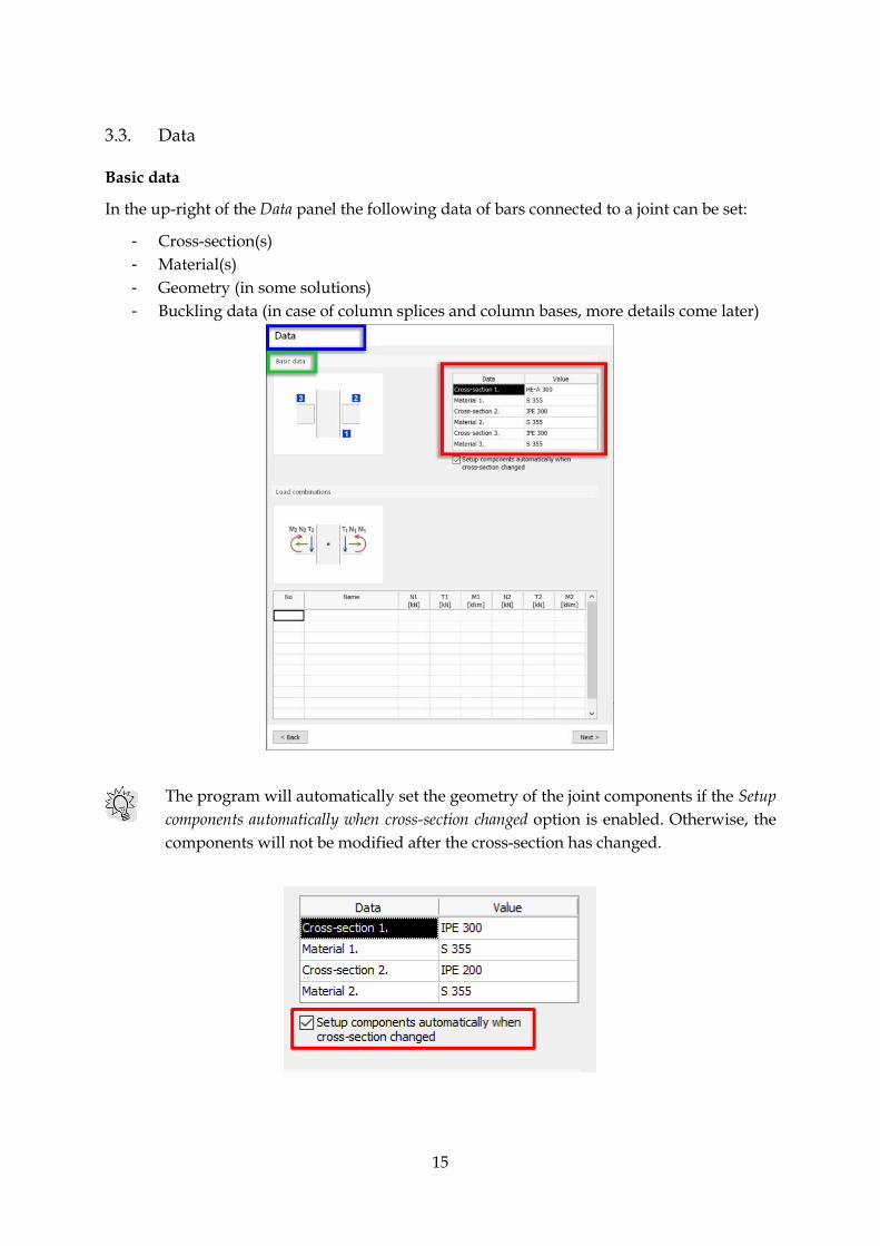
3.3. Data
Basic data
In the up-right of the Data panel the following data of bars connected to a joint can be set:
- Cross-section(s)
- Material(s)
- Geometry (in some solutions)
- Buckling data (in case of column splices and column bases, more details come later)
The program will automatically set the geometry of the joint components if the Setup
components automatically when cross-section changed option is enabled. Otherwise, the
components will not be modified after the cross-section has changed.

16
a. Cross section
The section library displays only those sections that are relevant for selected joint type. The
library can be exported to a file, or imported from a file.
In the cross-section library only the same type of sections can be imported.
If a new section needs to be created, or the user wants to modify or delete the existing
sections, it can be done in the Edit section library dialog, or by launching the Section Editor
from the Tools menu (or the Toolbar).
For more information about section editing, see FEM-Design User Manual, Structure
Definition -> Properties -> Cross-section chapter.

17
b. Material
The material library contains some standard steel grades. The library can be exported to a
file, or imported from a file.
In the material library there is a new partial factor called Gamma M5, which refers to the resistance of hollow and pipe sections (see Eurocode 1993-1-8, 2.2).
The user can create a new material by pressing the New button.

18
c. Geometry
In case of some joints it is possible to define the inclination of bars.
d. Buckling data
In some joints buckling data are present. They are considered in automatic calculation of 2nd
order effects, if necessary.
Load combinations
Load combinations can be defined at the bottom of the Data panel.

19
A selected load combination can be deleted by pressing Delete.
The 2nd order effect is considered in column splice and column base joints. If 2nd order
calculation is marked by X in the Load combinations table, it is supposed that the internal
forces come from 2nd order calculation.
Otherwise, internal forces are supposed to come from 1st order calculations and 2nd
order effect is calculated automatically, based on the buckling data defined by the
user in the Basic data table.
The user can step forward to the Design panel by clicking on the Next button.

20
3.4. Design
Modify, add and remove components
In the Design panel, components of the joint (e.g. end plate, splice plate, bolts, weld, etc.) can
be modified. Additionally, some components such as stiffeners, haunches, etc. can be added
or removed by setting Yes/No option in Apply.
A selected component is always highlighted in orange color in the 3D model.
Bolts
By selecting Bolts the user can define the bolt’s size, quality and other parameters.
The Bolt library provides a possibility to create, modify, and delete the bolts, as well as the
import or export from / to a file.

21
a. Bolt size
Click on bolt
“Value”
Click on bolt “Edit library”
Set bolt sizes

22
b. Bolt position in general case
In general cases (like splice plates, fin plates, etc.) the number of the bolt rows, columns,
distance between the columns (c) , distance between the rows (e) and the distance of the first
row from the plate’s edge (e0) can be set by the user. The bolt columns are automatically
positioned symmetrically in the plate.
The bolts arrangement figure is automatically refreshed when changes are applied.
If in some cases, the bolts arrangement drawing and the dimensions are too small or too big,
it is because the figure is not scaled properly. The user has the opportunity to change the
scale of the drawing in order to see the figure clearly.
Explanation figure
Bolt position parameters
Bolt arrangement figure
2. Set the scale by wrinting into the textbox or selecting the
proper value
Bad scaling Proper scaling
1. Right click in the figure

23
c. Bolt position in end plate for moment-resistant joints
In case of end plates for moment-resistant joints the user has more possibilities to define the
bolts position.
There may be either 2 or 4 bolts in a row and the distance between the inner bolts (c1) and
the outer bolts (c2) have to be set. Then for each row the user can define the:
- Number of the bolts
- Distance of the row relative to one of the following positons:
Top flange
Bottom flange
Top haunch (if available)
Bottom haunch (if available)
Bottom plate edge
Top plate edge
Previous bolt row
Change solution
Change solution button is located in the bottom-right of the Design panel. A joint solution can
be changed only if there is/are another solution(s) available (if the button is active). When
the solution is changed, internal forces will remain the same.

24

25
3.5. Calculation window
Content
Utilizations and a failure mode of the joint are displayed in the Calculation dialog. Each
calculation has a reference to the specific standard.
The calculation results can be displayed either for the maximum, or for selected load
combination.
Moving the calculation window
The Calculation window is located at the bottom left corner as default, but the user can
relocate it by docking the window to the blue arrows shown below.

26
When the Calculation window is docked on the bottom-left (default solution) it is not
visible in the interface in Joint and Data panels – only in Design panel.
If the user wants to see the window in all interfaces, then it should be relocated to
one of the remaining four docking positions.
3.6. Collection
The purpose of Collection is to collect and document the joints that belong to one model.
When a joint is designed, it can be added to the collection by clicking on Finish button and
assigning a name to it.
After saving the designed joint, a new joint can be started. Designed joint can be reloaded
from the list for modification.
Any joint in Collection can be displayed in a separate dialog along with a 3D model of it. In
this dialog the user can rename, copy or delete the joints.

27
The 3D preview area behaves like the model space in other modules, therefore:
- right clicking in the model space will pop up the view commands,
- dragging the view by holding the middle mouse button will animate pan the
view,
- using the wheel on the mouse will zoom in and out the model view,
- using CTRL + middle mouse button will animate rotate the model view.
Saved joints
Joint 3D preview

28
3.7. Documentation
General
FEM-Design automatically generates documentation for each joint added to the Collection.
The documentation is located in Documentation module.
The documentation contains the input data of the joint (Member data, Load combinations,
data of all components) and detailed calculations, so called detailed result.
Printing
a. Setup a printer
The printing process requires a printer(s) associated with the section(s) of the current
documentation. If a section does not have a defined printer (Undefined), you can add one by:
- selecting the section name in the document list (1),
- pressing Properties button in the Control panel (2),
- pressing Printer setup button (3),
- Selecting a printer from the dropdown list (4).
Click on the Documentation icon
to enter Documentation module
v

29
If you assign a PDF printer all sections, you can save your documentation as a PDF
file.
b. Print range
The completed document, or only some parts of it, can be printed out with Control Panel’s
Print tool or File -> Print document.
The user can set the Page rage as:
- All -> The whole document (all pages) will be printed out.
- Selection -> The objects selected in the Control panel (multi-selection also works) and
their pages will be printed out.
- Pages -> Only selected pages will be printed. Enter page number and/or page ranges
by separating with commas and by using “-“ (an example: 1,10,15-20,25, etc.).

30
Export to .docx format
It is possible to export the documentation into the Office OpenXML (.docx) file. In the
Documentation module press the Save as .docx button at the bottom right corner of the Control
panel.
Save as Office open XML (docx) document dialog will appear. Here the user can decide the
followings:
- here to save the result file,
- which MS Office Word template file to use (optional),
- whether to mark the Documentation Sections in comments or not (only in
Documentation module).

31
The own template must be based on the original template file called Template for fem-
design document templates.dotx located in your local user folder at your PC in
Documents\FEM-Design document templates folder, as this file contains the style
required for the correct export.
MS Office Word 2007 or newer is required for opening files with .docx distribution.
It is highly recommended to mark the documentation sections in the exported file, since the
page rendering in MS Word and in FEM-Design are different. Furthermore, the exported
document has A4 format pages. Therefore, if there are pages in the FD Documentation with
different size, it is easier to find them and change their size in the result .docx file with
section marks.
Using own Word templates is useful when the FEM-Design documentation contains Title
block, since it is not possible to export it to .docx. As an alternative, the user can create a
Word template with custom headers and footers, and use it for the export.
Since MS Word has more sophisticated solutions for creating the table of contents,
FEM-Design does not export it to the .docx document. However, the chapters are
exported therefore, the table of contents can be created in MS Word easily.
More information and useful hint can be found in the Save as .docx FAQ document
accessible from the Help menu.
Advanced documentation tools
Documentation module is a powerful tool that allows you to create multi-page
documentation with titles, figures, texts, tables, images, headers, footers, table of content etc.
In order to find out more about all the possibilities that the documentation module can offer,
please read the Documentation -> Documentation module chapter in FEM-Design User Manual.