Embed Size (px)
Citation preview
R. Toutant, S. Balakrishnan, S. Onyshko, and N. Popplewell
he results of’ an investigation into the design of an adaptive T force control system for tuming are presented here. The control system modifies the feedratz i n real time in order to keep the cutting force constant, while maintaining the accuracy of the tool path. The approach is unique in that a computer simulation is used off-line to determine the control system gains that allows a stable operation over a wide ranse of spindle speeds. inde- pendent of workpiece material. The scheme has been imple- mented successfully on an experimental lathe, and the results from an actual machining operation are presented.
Setting Feedrates and Cutting Speeds Computer numerical control (CNC) machine tools, such as
lathes and milling machines, are capable of positioning a tool accurately by using programmed commands. However, a ma- chinist still has to manually select parameters such as feedrate and cutting speed. Standard machining handbooks are available which suggest common feedrates and cutting speeds for given machining conditions [ I ] , [2]. They generally offer only a start- ing point and the resulting parameters are far from optimum. To alleviate this problem, various techniques have been investigated [3]-[ 111 whose objective is to modify the operating parameters in real time.
R. Toutant is Mith the Departnient of Ad\uiiced Technology, MPR Teltech, Ltd., Burnaby, Canada V3H 2K4. S . Onyshko is MYth the Department of Electrical Engineering, Unii-rrsity of Manitoba, Winnipeg, MB, Canada R3T 2N2. S. Balaki-ishnan and N . Pop- plewell are Mith the Department of Mechanical Engineering, University of Manitoba, Winnipeg, MB, Canada R3T 2N2.
44
Normal machining practice [ 121 suggests the use of the high- est feedrate possible, subject to the limitations of available ma- chine power, tool strength, and surface roughness tolerances. Various techniques to maximize the feedrate for a specified cutting force have been proposed in the past. For example, a variable-gain adaptive control system was proposed which em- ployed a compensator gain that was updated in real time to ensure a stable control loop for tuming [3]-[7], but a technique for selecting the adaptation gains was lacking. Model reference adaptive controls schemes have also been proposed for tuming as well as milling [8], [9], but the particular algorithms produced significant oscillatory behavior at low depths of cut.
The scheme presented here overcomes the above limitations by using offline numerical simulations which predetermine the optimum control system gains for a tuming operation. It is unnecessary to generate a complicated database approach since the simulations depend only upon easily measurable physical parameters. The resulting system maintains a near-constant cut- ting force throughout the metal removal cycle, independent of workpiece material and machining parameters, such as the depth of cut.
Position Control System The accuracy of the path followed by the tool during cutting
is crucial to the machine’s performance. A position control sys- tem is required, therefore, to ensure that the tool will follow an accurate path. The position control system is modeled as shown in Fig. 1. The servomotor/servoamplifier shown in this figure incorporates a forward gain of KO and a velocity feedback with a gain of K1. Both gains are selected using hardware incorporated
0272-1 708/93/$03.0001993IEEE IEEE Control Systems
I I I I I Position Feedbadc L _ _ _ _ _ _ _ _ _ J
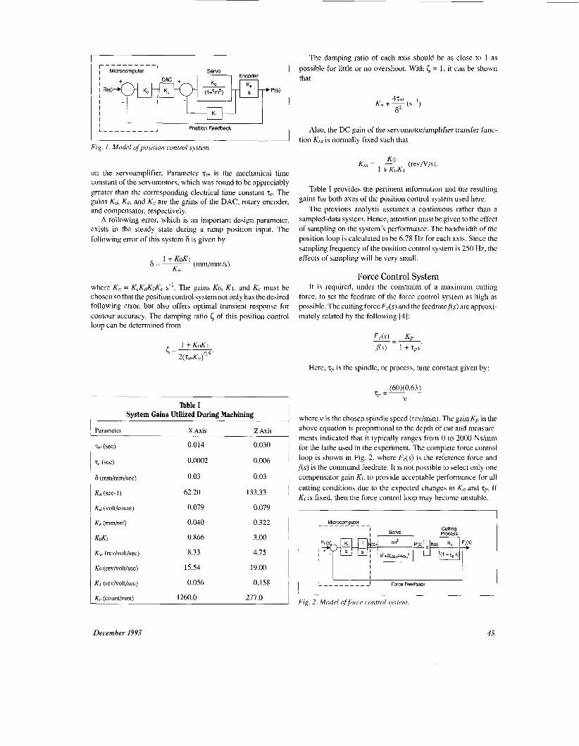
Fig. 1. Model of position control system.
on the servoamplifier. Parameter zm is the mechanical time constant of the servomotors, which was found to be appreciably greater than the corresponding electrical time constant ze. The gains Kd, Ke, and Kc are the gains of the DAC, rotary encoder, and compensator, respectively.
A following error, which is an important design parameter, exists in the steady state during a ramp position input. The following error of this system 6 is given by
where Kn = KcKdK& s-'. The gains KO, K i , and Kc must be chosen so that the position control system not only has the desired following error, but also offers optimal transient response for contour accuracy. The damping ratio of this position control loop can be determined from
Table I System Gains Utilized During Machining
Parameter X Axis 2 Axis
Tni (SeC)
ze (set)
6 (mm/mm/sec)
K, (sec-1)
Kd (voltkount)
Ke ("/ref)
KOKI
K, (rev/volt/sec)
KO (rev/volt/sec)
KI (rev/volt/sec)
K, (counv'mm)
0.014
0.0002
0.03
62.20
0.079
0.040
0.866
8.33
15.54
0.056
1260.0
0.030
0.006
0.03
133.33
0.079
0.322
3.00
4.15
19.00
0.158
277.0
December 1993
The damping ratio of each axis should be as close to 1 as = 1, it can be shown possible for little or no overshoot. With
that
Kn + ~ 4% ( s - ' )
F 2
Also, the DC gain of the servomotor/amplifier transfer func- tion K,, is normally fixed such that
Table I provides the pertinent information and the resulting gains for both axes of the position control system used here.
The previous analysis assumes a continuous rather than a sampled-data system. Hence, attention must be given to the effect of sampling on the system's performance. The bandwidth of the position loop is calculated to be 6.78 Hz for each axis. Since the sampling frequency of the position control system is 250 Hz, the effects of sampling will be very small.
Force Control System It is required, under the constraint of a maximum cutting
force, to set the feedrate of the force control system as high as possible. The cutting force F&) and the feedratef(s) are approxi- mately related by the following [4]:
Here, zp is the spindle, or process, tune constant given by:
(60)( 0.63) zp = ~
V
where v is the chosen spindle speed (revlmin). The gain Kp in the above equation is proportional to the depth of cut and measure- ments indicated that it typically ranges from 0 to 2000 Ns/mm for the lathe used in the experiment. The complete force control loop is shown in Fig. 2, where F&) is the reference force and f(s) is the command feedrate. It is not possible to select only one compensator gain Ki, to provide acceptable performance for all cutting conditions due to the expected changes in Kp and z,. If Ki is fixed, then the force control loop may become unstable.
I MiCrOCOmDuter I
I I I I
Fig. 2. Model offorce control system.
45
It is still necessary to select, on-line, an optimal value of Kj. Now, the transfer function of the forward path of the force control system is given by
where
and
There exists a value of Kr for each value of T~ that will provide an optimum response to changes in the process gain Kp. The approach used here is to determine the optimum values of Kt versus spindle speeds by using off-line numerical simulations which minimize the performance index ITAE, given by the following equation, for a step change in the cutting force F,:
[ t I Fr(t) - F,(t) I dt. 0
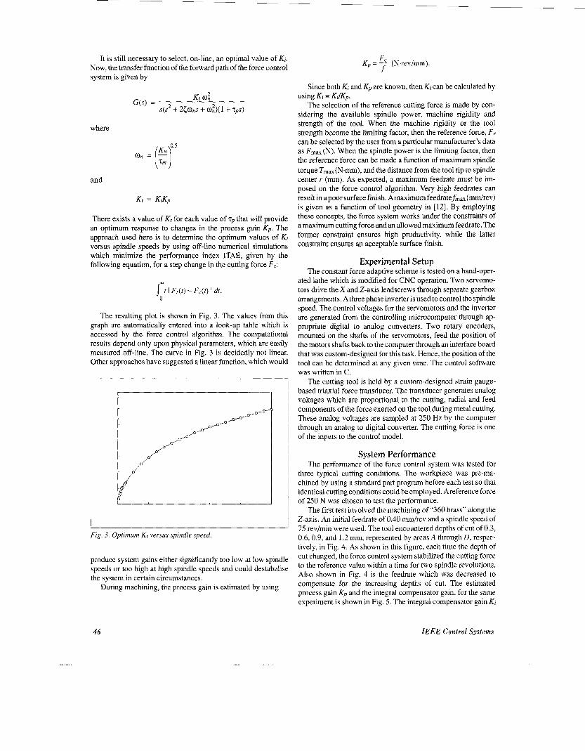
The resulting plot is shown in Fig. 3. The values from this graph are automatically entered into a look-up table which is accessed by the force control algorithm. The computational results depend only upon physical parameters, which are easily measured off-line. The curve in Fig. 3 is decidedly not linear. Other approaches have suggested a linear function, which would
Fig. 3. Optimum Kt versus spindle speed.
produce system gains either significantly too low at low spindle speeds or too high at high spindle speeds and could destabalise the system in certain circumstances.
During machining, the process gain is estimated by using
F Kp = (N.rev/mm). f
Since both Kt and Kp are known, then Kj can be calculated by
The selection of the reference cutting force is made by con- sidering the available spindle power, machine rigidity and strength of the tool. When the machine rigidity or the tool strength become the limiting factor, then the reference force, F r can be selected by the user from a particular manufacturer’s data as Fm, (N). When the spindle power is the limiting factor, then the reference force can be made a function of maximum spindle torque Tmax(N.mm), and the distance from the tool tip to spindle center r (mm). As expected, a maximum feedrate must be im- posed on the force control algorithm. Very high feedrates can result in apoor surface finish. Amaximum feedratefmax (“/rev) is given as a function of tool geometry in [ 121. By employing these concepts, the force system works under the constraints of a maximum cutting force and an allowed maximum feedrate. The former constraint ensures high productivity, while the latter constraint ensures an acceptable surface finish.
Using Ki = KtIKp
Experimental Setup The constant force adaptive scheme is tested on a hand-oper-
ated lathe which is modified for CNC operation. Two servomo- tors drive the X and Z-axis leadscrews through separate gearbox arrangements. A three phase inverter is used to control the spindle speed. The control voltages for the servomotors and the inverter are generated from the controlling microcomputer through ap- propriate digital to analog converters. Two rotary encoders, mounted on the shafts of the servomotors, feed the position of the motors shafts back to the computer through an interface board that was custom-designed for this task. Hence, the position of the tool can be determined at any given time. The control software was written in C.
The cutting tool is held by a custom-designed strain gauge- based triaxial force transducer. The transducer generates analog voltages which are proportional to the cutting, radial and feed components of the force exerted on the tool during metal cutting. These analog voltages are sampled at 250 Hz by the computer through an analog to digital converter. The cutting force is one of the inputs to the control model.
System Performance The performance of the force control system was tested for
three typical cutting conditions. The workpiece was pre-ma- chined by using a standard part program before each test so that identical cutting conditions could be employed. Areference force of 250 N was chosen to test the performance.
The first test involved the machining of “360 brass” along the Z-axis. An initial feedrate of 0.40 “/rev and a spindle speed of 75 rev/min were used. The tool encountered depths of cut of 0.3, 0.6,0.9, and 1.2 mm, represented by areas A through D , respec- tively, in Fig. 4. As shown in this figure, each time the depth of cut changed, the force control system stabilized the cutting force to the reference value within a time for two spindle revolutions. Also shown in Fig. 4 is the feedrate which was decreased to compensate for the increasing depths of cut. The estimated process gain Kp and the integral compensator gain, for the same experiment is shown in Fig. 5. The integral compensator gain Ki
46 IEEE Control Systems

A I 6 C I D
-/ 1.2
0 0 0 2 4 6 8 10 12 14 16 18 20 22
Time (sec)
Fig 4 Cutting foice and feedrate for machining “360 hiasp,” 7s ‘Pm
0.0:
0.0;
0.01
0.oc
f 1000
I A I B I C I I D I
2 4 6 8 10 12 14 16 -18 20 22-
Time (sec)
Fig. 5. Estimatedprocess gain and compensator gain for machining “360 brass.”
decreased from approximately 0.020 to 0.003 mm/N.rev during machining.
The experiment was repeated using the same brass workpiece with a spindle speed of 350 rev/min. In this case, the cutting force was retumed to the reference value within the time for three spindle revolutions. A third test with “6061 a1uminum”machined at a spindle speed of 1050 rev/min was performed, and the cutting force was again stabilized within three spindle revolutions. Ad- ditional tests were performed with various kinds of steel using a variety of metal removal rates, and the system exhibited a stable and predictable response to changes in the machining process.
Maximization of Feedrate A machine tool controller has been developed and tested for
the control of the cutting force during tuming. Both a position
control system and an adaptive force control system have been developed. The force control system modifies the feedrate on- line to keep the cutting force constant, with the aim being a more optimum machining process. An adaptive control loop is utilized to ensure a stable but fast-acting system. Numerical simulations were used off-line to predetermine the control system gains which ensure a robust operation over a wide range of machining operations. Unlike other schemes, adaptation gains are system- atically selected based only upon a performance criterion and physical parameters which are easily measured.
Our work has focused on the maximization of the feedrate to reduce the machining time under the constraint of a maximum cutting force. An advantage of this scheme is that it is unneces- sary to generate a complicated database for its operation. Com- bining such an approach with the control of the cutting speed and possibly under the additional constraint of a contour error [ 111 will also be considered in the future to further increase produc- tivity.
References [I ] The Machining Handbook, 3rd ed., Metcut Research Associates, Ma- chinability Data Center, Cincinnati, OH, 1980.
[2] E. Oberg and E Jones, Machiner-y:y Handbook-, 19th ed. New York: Industrial Press, 1974.
[3] A. Ulsoy, Y. Koren, and E Rasmussen, “Principal developments in the adaptive control of machine tools,” .1. Dynamic, Sysr.. Mrasirremeni. and Control, vol. 105, pp. 107.112, June 1983.
[4] 0. Masory and Y. Koren, “Stability analysis of a constant force adaptive control system for turning,"./. Ens. Ind., vol. 107, pp, 295-300, Nov. 1985.
[ S ] 0. Masory, “Real-time estimation of cutting process parameters in tuming,”J. Eng. Ind., vol. 106, pp. 218-221, Aug. 1984.
[6] 0. Masory and S. Lin, “Gains selection for a variable gain adaptive control system for tuming,”J. E n g . Ind., vol. 109, pp. 399403, Nov. 1987.
[7] M. Tomizuka and S. Zhang, “Modeling and conventional/adaptive PI control of a lathe cutting process,”J. Dymmic. Sysr., Meas. Corirrol, vol. 1 IO, pp. 35C354, Dec. 1988.
[8] L. Daneshmend and H. Pak, “Model reference adaptive control of feed force in tuming,” J . Dynamic Sysr., Meas. Control, vol. 108, pp. 215-222, Sept. 1986.
[9] L. Lauderbaugh and A. Ulsoy, “Dynamic modeling for control of the milling process,” J . Eng. Ind., vol. 110, pp. 367-375, Nov. 1988.
[ lo] R. Bedini and P. Pinotti, “Experiments on adaptive constrained control of a CNC lathe,”./. Eng. Ind., vol. 104, pp. 139-149, May 1982.
[ I l l F. Imamura and H. Kaufman, “Time optimal contour tracking for machine tool controllers,” IEEE Control Syst. Mag., vol. 11, no. 3, pp. 11-1 7, Apr. 1991.
[ 121 T. Drozda and C. Wick, Tool and Manufacricring €riginerrs Handbook, Society of Manufacturing Engineers, Dearbom, MI, 1983.
Photographs and biographies of the authors not available at time of publication.
December 1993 47


![SIMPLIFICATION OF TURNING POINT PROBLEMS FOR …...1963] TURNING POINT PROBLEMS 103 constant rank r, and let b(z) be a vector function holomorphic at z = 0. If the equation (3.2) A(z)w(z)](https://img.pdfslide.us/doc/110x75/5f07889f7e708231d41d74ed/simplification-of-turning-point-problems-for-1963-turning-point-problems-103.jpg)