Embed Size (px)
Citation preview

User’s Manual
PART NO. IB034181Apr 2019
400W model
PWR401L PWR401MLPWR401MH PWR401H800W model
PWR801L PWR801MLPWR801MH PWR801H1200W model
PWR1201L PWR1201MLPWR1201MH PWR1201H2000W model
PWR2001L
Regulated DC Power Supply PWR-01 Series
Component Names 8Installation and Preparation 13
Connecting the Power Cord 14Load Considerations 19
Selecting the Load Cables 21Output Terminal Insulation 23
Connecting to the Output Terminals 25Turning the Power On 32
Remote Sensing function 34Basic Features 37
Measured Value Display and Setting Display 38Panel Operations 40Output Operation 41
Operation Overview 45CV Power Supply and CC Power Supply 47
Using the PWR-01 as a CV or CC Power Supply49
Protection functions 50CONFIG Settings 60
Preset Memory function 77Locking Panel Controls (Key Lock) 78
CONFIG Shortcut function 79Switching from Remote Mode to Local Mode 80
Advanced Features 81Bleeder Circuit function 82
Variable Internal Resistance function 84Sequence function 85
Synchronized Operation 86External Control 89Product Operation 90
About the J1/ J2 Connectors 90Notes for Connecting External Voltage (Vext) 94
Output voltage control 96Output Current Control 98
Controlling the Output On and Off States 100Controlling Output Shutdown 102
Controlling the Clearing of Alarms 103External Monitoring 104
Parallel/ Series Operation 107Master-Slave Parallel Operation 108
Series operation 114Maintenance 119
Calibration 120Cleaning 122
Specifications 123400W model 125800W model 128
1200W model 1312000W model 134
Common specifications 137
Appendix143
2 PWR-01
These manuals are intended for users of the Regulated DCPower Supply and their instructors. Explanations are givenunder the presumption that the reader has knowledge of theelectrical aspects of regulated DC power supplies.
PWR-01 manual construction
User’s manual (this manual, PDF)This manual is intended for first-time users of this product. Itprovides an overview of the product, notes on usage, andspecifications. It also explains how to configure the product,operate the product, perform maintenance on the product,and so on.Please read this manual before you operate the product.
Communication interface manual (PDF)This manual describes remote control and multichannel(Virtual Multi Channel Bus).The interface manual is written for readers with sufficientbasic knowledge of how to control power supplies using aPC.
Quick ReferenceThis document briefly explains the PWR-01 panel and thebasic operation of it.
Safety InformationThis document contains general safety precautions. Keepthem in mind and make sure to observe them.
PDF files are included in the accompanying CD-ROM.You can view the PDF files using Adobe Reader.
Firmware versions that this manual coversThis manual applies to products with firmware versions 1.2X.When contacting us about the product, please provide us withthe following information.
Model (marked in the top section of the front panel)Firmware version (see page 32)Serial number (displayed on the top panel).
TrademarksMicrosoft, Internet Explorer, and Windows are registeredtrademarks or trademarks of Microsoft Corporation in theUnited States and/or other countries.All company names and product names used in this manualare trademarks or registered trademarks of their respectivecompanies.
CopyrightsThe contents of this document may not be reproduced, inwhole or in part, without the prior consent of the copyrightholder.The specifications of this product and the contents of this doc-ument are subject to change without prior notice.© 2019 Kikusui Electronics Corporation
About the PWR-01 Manuals

PWR-01 3
The PWR-01 series is a constant voltage (CV)/constant cur-rent (CC) automatic crossover power supply that can output awide range of voltage and current within rated output power.The products in this series are divided into the following fourmodels depending on the output capacity. They are dividedinto four types depending on the output voltage.
FeaturesCommunication function
RS232C, USB, and LAN interfaces are all installed as stan-dard. The remote interfaces comply with IEEE Std 488.21992 and SCPI Specification 1999.0.The LAN interface complies with the LXI standard. Multi-channel (VMCB), which controls up to 31 PWR-01s from asingle PC, can be used to construct a multichannel powersupply system.
Master-slave parallel operationYou can increase the output current by connecting up tothree PWR-01s (two units for the 1200W model and 2000Wmodel) in parallel. You can set one unit as the master unit,and control the remaining units as slave units.If an error occurs in a slave unit, the master unit detects thealarm and shuts down the output of the entire system.
Setting preset memory functionYou can save up to three sets of output settings (the combi-nation of the voltage, current, OVP, OCP, and UVL). Youcan simply select a set of output settings that you want touse rather than having to specify each setting every time.
Automatic output-on settingYou can set the PWR-01 so that when a low AC input pro-tection function (AC-FAIL) is activated and the output isturned off, the output is automatically turned back on whenthe problem that caused the output to turn off is fixed.
Output-on/off delay functionYou can set the delay (DELAY TIME) from when the OUT-PUT key is turned on or off to when the output actually turnson or off. This is useful when you want to turn the output onor off by setting a delay according to the load characteris-tics.
Set voltage/current limitation functionYou can apply limits to the voltage and current settings. Thisprevent you from setting an appropriate value by mistake,which would cause the output to turn off.
Accessories
or or
※ Lタイプ、MLタイプ のみ付属
[M3-112-027]
[M1-100-012]
[M4-100-007][M5-100-007]
[M5-101-007]
[M1-100-020]
[M4-100-008][M5-100-008]
[M5-101-008]
[M3-112-018]
[M3-112-015]
[P4-000-551]
[96-01-0370]
[D6-750-001][P1-000-410]
Output terminal M4 screws (2 pcs.)
Chassis connection short bar (1 pc.) [E3-300-064]
<400W/ 800W/ 1200W model> <2000W model>
Output terminal bolt set (2 sets)* Only L type and ML type included.
Bottom [Q1-500-200]
Top [Q1-500-198]
Adapter [Q1-500-199]Bottom [Q1-200-077]
Top [Q1-200-075]
Adapter [Q1-200-076]
<400W/ 800W/ 1200W model> <2000W model>
M8 bolt set M10 bolt set
Power cord (1 pc.)
Rating: 125 VacPlug: NEMA5-15
Rating: 250 Vac Plug: CEE7/7Length: Approx. 2.5 m[85-10-1070]
Rating: 250 Vac Plug: GB1002Length: Approx. 2.5 m[85-10-0791]
• 400W model: Length: Approx. 2.5 m [85-AA-0004]• 800W model: Length: Approx. 3.0 m [85-10-1030]
Packing list (1 copy) Safety Information (1 pc.)
CD-ROM (1 disk)
Output terminal cover (1 set)
Quick Reference(Japanese: 1 pc, English: 1 pc.)
Input terminal cover (1 set) Ferrite core set (1 set)
Included only with the 400W/800W model
Included only with the 1200W model
The attached power cord varies depending on the shipment destination.
400W model 800W modelL type(40 V) PWR401L PWR801LML type(80 V) PWR401ML PWR801MLMH type(240 V) PWR401MH PWR801MHH type(650 V) PWR401H PWR801H
1200W model 2000W modelL type(40 V) PWR1201L PWR2001LML type(80 V) PWR1201ML –MH type(240 V) PWR1201MH –H type(650 V) PWR1201H –
Product Overview

4 PWR-01
Overcurrent protection (OCP) detection time settingYou can set the amount of time that an overcurrent mustpersist after the first detection of the overcurrent before theovercurrent protection (OCP) is activated. If inrush currentfrom the load causes an excessive current to flow temporar-ily, you can adjust the delay to prevent the overcurrent pro-tection (OCP) from being activated.
Bleeder circuit functionYou can turn the bleeder circuit on and off. Turn the bleedercircuit off when you do not want the internal bleeder circuitto sink output current. When you connect a battery, you canprevent excessive electrical discharges by turning thebleeder circuit off.
Soft start/ stop functionThis function can be used to control the rise time or fall timewhen the load voltage or current cannot follow the suddenrise or fall in the output current or when you want to avoidthe overvoltage or overcurrent protection from being acti-vated.
Variable internal resistance functionYou can easily simulate rechargeable batteries, solar bat-teries, fuel cells, and other power supplies that have internalresistance. By setting the internal resistance value in con-stant voltage (CV) mode, you can decrease the output volt-age according to the output current.
Sequence functionThe sequence function recalls conditions set in a programand runs automatically. If you write a program created on aPC into the PWR-01, you can execute the program from thepanel.When a program is written in the PWR-01, you can executethe program without a PC.
CONFIG setting shortcut function and displayYou can register CONFIG setting parameters to the frontpanel’s SC keys. Because you do not have to go into theCONFIG menu to set the parameters, you can perform testsefficiently by registering CONFIG parameters that you usefrequently. Up to three parameters can be registered.
When using this product, be sure to observe the “SafetyPrecautions” in the Safety Information manual.
When installing this product, be sure to observe the“Precautions Concerning Installation Location” in the Safetyinformation manual. The following precautions pertain only tothis product.
• When installing this product, be sure to observe thetemperature and humidity ranges indicated below.
Operating temperature range: 0 °C to +50 °C (32 °F to122 °F)Operating humidity range: 20 %rh to 85 %rh (nocondensation)
• When storing this product, be sure to observe thetemperature and humidity ranges indicated below.
Storage temperature range: -25 °C to +60 °C (-13 °F to140 °F)Storage humidity range: 90 %rh or less (no condensation)
Safety Precautions
Precautions ConcerningInstallation Location

PWR-01 5
• In this guide, the suite of products shown on the front coveris also referred to as the “PWR-01.”
• The term “PC” is used to refer generally to both personalcomputers and workstations.
• The illustrations of displays used in this manual may differfrom the actual displays. The illustrations are merely exam-ples.
• The following markings are used in the explanations of thistext.
Indicates a potentially hazardous situation which, ifignored, could result in death or serious injury.
Indicates a potentially hazardous situation which, ifignored, may result in damage to the product or otherproperty.
Indicates information that you should know.
Explanation of terminology or operation principle.
Indicates a reference to detailed information.
Indicates a reference to a manual containing detailedinformation.
CFxx: x“CF” indicates that this is a CONFIG parameter. The twodigits after CF indicate the CONFIG parameter number.The value after the colon indicates the selected setting.
SHIFT+key nameIndicates an operation that requires you to press a keywhile holding down SHIFT.
Indicates useful information.
Notations Used in This Manual
WARNING
CAUTION
DESCRIPTION
See
Memo
6 PWR-01
Contents
About the PWR-01 Manuals ..................2Accessories ...........................................3Product Overview ..................................3Features .................................................3Safety Precautions .................................4Precautions Concerning Installation Location .................................................4Notations Used in This Manual ..............5Component Names .................................8
1 Installation and Prepara-tionConnecting the Power Cord........................ 14
400W model/ 800W mode ................... 141200W model/ 2000W model............... 15
Load Considerations................................... 19Selecting the Load Cables.......................... 21Output Terminal Insulation.......................... 23
When the output terminal is not grounded (floating) ............................................... 23When the output terminal is grounded . 24
Connecting to the Output Terminals ........... 25Connecting to the rear-panel output terminals .............................................. 25Attaching the OUTPUT terminal cover. 27Connecting to the front-panel output terminals .............................................. 31
Turning the Power On................................. 32Turning on the POWER switch ............ 32Turning the POWER switch off ............ 33
Remote Sensing function............................ 34
2 Basic FeaturesMeasured Value Display and Setting Display.. 38Panel Operations ........................................ 40Output Operation ........................................ 41
Output on/off setting at power-on......... 41Output-on startup state parameter....... 42Output-on/ off delay setting.................. 42Soft start/ soft stop function ................. 43
Operation Overview .................................... 45CV Power Supply and CC Power Supply ... 47Using the PWR-01 as a CV or CC Power Supply......................................................... 49Protection functions .................................... 50
Alarm occurrence and clearing alarms 50
Output shutoff (alarm) protection function. 52Setting limit protection function ........... 58
CONFIG Settings ....................................... 60CONFIG parameter details ................. 64
Preset Memory function ............................. 77Saving settings.................................... 77Recalling settings ................................ 77
Locking Panel Controls (Key Lock)............ 78CONFIG Shortcut function ......................... 79
Registering CONFIG shortcuts ........... 79Using CONFIG shortcuts .................... 79
Switching from Remote Mode to Local Mode .. 80
3 Advanced FeaturesBleeder Circuit function.............................. 82Variable Internal Resistance function ........ 84Sequence function ..................................... 85
Writing and executing a sequence program............................................... 85
Synchronized Operation ............................ 86
4 External ControlProduct Operation...................................... 90About the J1/ J2 Connectors...................... 90Notes for Connecting External Voltage (Vext) . 94Output voltage control................................ 96
Control using an external voltage (Vext) ... 96Control using an external resistance (Rext) 97
Output Current Control............................... 98Control using an external voltage (Vext) ... 98Control using an external resistance (Rext) 99
Controlling the Output On and Off States 100Controlling Output Shutdown ................... 102Controlling the Clearing of Alarms ........... 103External Monitoring .................................. 104
5 Parallel/ Series OperationMaster-Slave Parallel Operation .............. 108
Features ............................................ 108Connection ........................................ 110Setting ............................................... 112Starting master-slave parallel operation.... 113
Series operation....................................... 114Features ............................................ 114

PWR-01 7
Connection ........................................ 116Setting ............................................... 117Starting series operation ................... 117
6 MaintenanceCalibration ................................................ 120
Calibration overview.......................... 120Calibration procedure ........................ 121
Cleaning ................................................... 122
7 Specifications400W model ............................................. 125800W model ............................................. 1281200W model ........................................... 1312000W model ........................................... 134Common specifications ............................ 137
Appendix
A Factory Default Settings ......144
B Options......................................146
C Troubleshooting......................149

8 PWR-01
Component Names
Front panel
10A MAXDC OUTPUT
CV
CC
/W
V
A
ALM RMT LOCK LAN
B CAPRESET
DLY SEQ HBSSVIR
CV
CC
/W
V
A
ALM RMT LOCK LAN
POWER MAX10ADC OUTPUTPOWER
SC2 SC3 LOCKALM CLR SC1 SHIFT
FINE
FINE
REGULATED DC POWER SUPPLY
OUTPUT
VOLTAGE
CURRENT
CONFIG PWR DSPLMEMORY LOCALSET OVP・OCP
CV
CC
/W
V
A
ALM RMT LOCK LAN
B CAPRESET
DLY SEQ HBSSVIR
CV
CC
/W
V
A
ALM RMT LOCK LAN
SC2 SC3 LOCKALM CLR SC1 SHIFT
FINE
FINE
REGULATED DC POWER SUPPLY
OUTPUT
VOLTAGE
CURRENT
CONFIG PWR DSPLMEMORY LOCALSET OVP・OCP
CV
CC
/W
V
A
ALM RMT LOCK LAN
B CAPRESET
DLY SEQ HBSSVIR
CV
CC
/W
V
A
ALM RMT LOCK LAN
SC2 SC3 LOCKALM CLR SC1 SHIFT
FINE
FINE
REGULATED DC POWER SUPPLY
OUTPUT
VOLTAGE
CURRENT
CONFIG PWR DSPLMEMORY LOCALSET OVP・OCP
CV
CC
/W
V
A
ALM RMT LOCK LAN
B CAPRESET
DLY SEQ HBSSVIR
CV
CC
/W
V
A
ALM RMT LOCK LAN
SC2 SC3 LOCKALM CLR SC1 SHIFT
FINE
FINE
REGULATED DC POWER SUPPLY
OUTPUT
VOLTAGE
CURRENT
CONFIG PWR DSPLMEMORY LOCALSET OVP・OCP
MAX10ADC OUTPUTPOWERMAX10A
DC OUTPUTPOWER
CV
CC
/W
V
A
ALM RMT LOCK LAN
B CAPRESET
DLY SEQ HBSSVIR
CV
CC
/W
V
A
ALM RMT LOCK LAN
SC2 SC3 LOCKALM CLR SC1 SHIFT
FINE
FINE
OUTPUT
VOLTAGE
CURRENT
CONFIG PWR DSPLMEMORY LOCALSET OVP・OCP
REGULATED DC POWER SUPPLY
POWER
18
16
171
1
1
1
1415
1920
20 2019
21
21
21
22 22
19PWR
1
20
21
21
22
19PWR
PWR
PWR7
8
9
6
5
234
10
1112
13
Controls
Controls
Controls
Controls
400W model
800W model 1200W model
2000W model
Controls

PWR-01 9
No. Name Function
1 POWER switch
400W model/ 800W model/ 1200W model: Power on/ off switch. Press the ( ) side to turn the power on and the ( ) side to turn the power off.2000W model: Power on/ off breaker. Flip the lever to the ( ) side to turn on and the ( ) side to turn off.
p.32, p.33
2 Voltmeter Displays the voltage, alarm, or CONFIG parameter number. p.38, p.60
3 OUTPUT LED
Lights green when output is turned on. Blinks orange during output-on delay. Blinks green during output-off delay. p.41
Blinks orange when output is on and a protection function is activated. p.50
Lights green during soft start. Blinks green during soft stop. p.43
4 Ammeter Displays the current, power, or the cause of an alarm, or the value of a CONFIG parameter. p.38, p.50, p.60
5 OUTPUT key Used to turn output on and off. p.41
6 VIR/ SS/ DLY/ SEQ/ HB
VIR: Lights when the variable internal resistance function is enabled.SS: Lights when the soft start/ stop function is enabled and blinks when it is in progress.DLY: Lights when the output-on/ off delay is enabled and blinks when it is in progress.SEQ: Lights when a sequence is being executed and blinks the PWR-01 is waiting for a trigger.HB: Lights when the hyper bleeder of the bleeder circuit is enabled.
p.84p.43p.42p.85p.82
7 PRESET A/ B/ C LEDA: Lights green when the memory A values are being recalled or saved.B: Lights green when the memory B values are being recalled or saved.C: Lights green when the memory C values are being recalled or saved.
p.77
8SET key Used to set and confirm the output voltage and output current (the key has an LED). p.38
ALM CLR key Used to release the activated state (alarm) of protection functions (the key has an LED). p.51
9OVP•OCP key Used to set and display the overcurrent protection (OCP), overvoltage protection (OVP), under-
voltage limit (UVL) trip points (the key has an LED). p.52, p.59
SC1 Used to call the CONFIG parameter shortcut (the key has an LED) p.79
10CONFIG key Used to configure the various operating conditions (CONFIG) (the key has an LED). p.60
SC2 Used to call the CONFIG parameter shortcut (the key has an LED) p.79
11VOLTAGE knob Used to set the voltage value or select the value of a CONFIG parameter. p.40, p.60
FINE Used to make fine voltage value adjustments. p.40
12 CV LED Lights green during constant voltage mode. p.49
13 CC LED Lights red during constant current mode. p.49
14CURRENT knob Used to set the current, change the value of a CONFIG parameter, or set the internal resistance
value.p.40,
p.60, p.65
FINE Used to make fine current or internal resistance value adjustments. p.40, p.65
15
ALM LEDLights red when a protection function is activated. However, when the undervoltage limit (UVL) is activated, the LED does not light. When the power limit (POWER LIMIT) is activated, the LED blinks.
p.78
RMT LED Lights green when the PWR-01 is being remotely controlled p.80
LOCK LED Lights green when the keys are locked. p.78
LAN LEDLights and blinks when the LAN interface is running.• No fault status (green) • Fault status (red)• Standby status (orange) • Identify status (blinking green)
Communi-cation
Interface Manual
16LOCAL key Used to switch between local mode and remote mode (the key has an LED) and switch the CON-
FIG parameter display. p.80
SHIFT key Used to enable the functions that are written in blue characters below the key. –
17PWR DSPL key Used to display the output power on the ammeter (the key has an LED). p.38
LOCK key Used to lock the operation of all keys other than the OUTPUT key (key lock) (the key has an LED). p.78
18MEMORY key Used to load and save the value of preset memory A, B, or C (the key has an LED). p.77
SC3 Used to call the CONFIG parameter shortcut (the key has an LED). p.79
19 Air inlet (louver) Air inlet for cooling. p.122
20 DC OUTPUT connector Front-panel output terminal. p.31
21 Rubber feet 400W model/ 800W model/ 1200W model: Four locations on the bottom.2000W model: Four locations on the bottom, four locations on the side. p.147
22 Handle Handle for carrying. p.147
See

10 PWR-01
Rear Panel
J1
J2 J2
J1
J2
J1
J1
J2
100-240V/ 50-60Hz2800VA MAX
N
L
AC INPUT
AC INPUT
100-240V600VA MAX
50-60Hz
AC INPUT
100-240V1680VA MAX
50-60Hz
AC INPUT
50-60Hz 100-240V 560VA MAX
7
4 5 6
1
3
2
9
810
11
400W model
10
11
8
9
1200W model
10
11
8
9
800W model
10
11
2000W model
9
8
Connetion Connetion
Connetion
Connetion
Connetion

PWR-01 11
No. Name Function
1 DC OUTPUT terminal Rear-panel output terminal. p.25
2 Chassis terminal A connector for grounding the output. p.25
3 LAN port1 Ethernet port for controlling the PWR-01 remotely.
CommunicationInterface Manual
4RS232C/ TRG IN connector1
RS232C port for controlling the PWR-01 remotely.Trigger signal input connector. The common terminal is connected to the chassis.
5 TRG OUT connector1Trigger signal output terminal. The common terminal is connected to the chassis.
6 USB port1
1. A connector cover or terminal cover is attached when the product is shipped from the factory.
USB port for controlling the PWR-01 remotely.
7 Sensing terminal Terminals to connect the sensing cables to. p.34
8 Air outlet Air outlet for internal cooling. –
9 AC INPUT400W model/ 800W model: AC inlet.1200W model/ 2000W model 2: AC INPUT terminal block.
2. A terminal block cover is attached when the product is shipped from the factory (2000W model only).
p.14p.15
10 J1 connector1 For external control and master-slave parallel operation. p.90, p.110
11 J2 connector1 External control p.90
See

12 PWR-01
This page is intentionally blank.

Installation and PreparationThis chapter describes how to turn on thePWR-01, what kind of load cables to use,and how to connect cables to the outputterminals.

14 PWR-01
Connecting the Power Cord
This product conforms to IEC Overvoltage Category II (energy-consuming equipment that issupplied from a fixed installation).
400W model/ 800W mode
1 Check that the AC power line meets the nominal input rating of the prod-uct.The product can receive a nominal line voltage in the range of 100 Vac to 240 Vac at50 Hz or 60 Hz.
2 Check that the POWER switch is turned off.
3 Connect the power cord to the AC inlet on the rear panel.
4 Insert the power plug into a grounded outlet.
WARNING Risk of electric shock.This product conforms to IEC Safety Class I (equipment that has a protective conduc-tor terminal). Be sure to earth ground the product to prevent electric shock.
WARNING Risk of electric shock.The product is grounded through the power cord ground wire. Connect the protective conductor terminal to earth ground.
• Use the included power cord to connect to the AC line.If the supplied power cord cannot be used because the rated voltage or the plug shape is incompatible, have a qualified engineer select an appropriate power cord that is 3 m or less in length.
• The power cord with a plug can be used to disconnect the product from the AC power line in an emergency. Connect the plug to an easily accessible power outlet so that the plug can be removed from the outlet at any time. Be sure to provide adequate clearance around the power outlet.
• Do not use the dedicated power cord with other instruments.

PWR-01 15
Installation and Preparation| Connecting the Power Cord
1200W model/ 2000W model
A power cord is not included with the 1200W model and 2000W model. Use a power cordthat conforms to the rated AC input voltage and current of this product.The following dedicated power cord is available as an option.
If you will not use one of the optional input power cords, prepare a power cord that meets thefollowing specifications.
Tightening torque of input terminal connection screws
WARNING Risk of electric shock.• Before you connect the power cable, turn off the switchboard breaker (a switch that
cuts off the power supply from the switchboard).Risk of fire.
• Be sure to have a qualified engineer make the connection to the switchboard.• The switchboard breaker must meet the requirements shown below.
CAUTION Inside the product, protection circuits are connected to match the polarity of the input termi-nal. Be sure to connect the L, N, and (GND) terminals correctly between the switchboard and the product.
• We recommend that you use the optional dedicated power cord to connect to the AC power line. If you will not use the dedicated power cord, use an appropriate power cord with a length of 3 m or less that has been selected by a qualified technician.
• In an emergency, turn off the switchboard breaker to separate the product from the AC power line.
1200W model Finished diameter: 12.1 mm or lessRated voltage: 250 V or higherVinyl cabtire cable (VCTF)Nominal cross-sectional area 5.5 mm2 3 core Input terminal end: Ring terminal 5.5-4 (5.5 mm2 M4))
2000W model Nominal cross-sectional area 5.5 mm2 Single core, 3pcs.Input terminal end: Ring terminal 5.5-6(5.5 mm2 M6)
Tightening torque [N・m]
M4 1.33
M6 3.0
AC5.5-3P3M-M4C-VCTF(not CE compliant)
For the 1200W model
AC5.5-1P3M-M6C-3S(CE compliant)
For the 2000W model

16 PWR-01
Installation and Preparation| Connecting the Power Cord
Switchboard breaker requirements
• Rated currentFor safety reasons, circuit breakers exceeding the specified current cannot be used.1200W model: 30 A (100 V system), 15 A (200 V system)2000W model: 50 A (100 V system), 30 A (200 V system)
• Only use the breaker with this product.• Keep the breaker readily accessible at all times.• Indicate that the circuit breaker is dedicated for use with this product and that it is used
to disconnect the product from the AC power line.
Connection procedure of 1200W model
1 Check that the AC power line meets the nominal input rating of theproduct.The product can receive a nominal line voltage in the range of 100 Vac to 240 Vac at50 Hz or 60 Hz.
2 Check that the POWER switch is turned off.
3 Connect the power cord to the AC INPUT terminal on the rear panel.Pass the power cord through the included INPUT terminal cover, and fixthe cord in place using the lock plate and screws.Be sure to connect the L, N, and (GND) of the AC input terminal correctly.
400W model 800W model 1200W model 2000W model
Protective conductor current(at 265 Vac, 60 Hz) 1.5 mA 2.5 mA 4.0 mA 4.7 mA
Inrush current 25 Amax 50 Amax 75 Amax 125 Amax
PWR1201L
Switchboard
Circuit breaker indication example
PWR1201L dedicatedPWR1201Ldedicated circuit breaker
NL
NL
PWR1201L model
Input terminal cover
N L
(GND)
AC INPUT terminal block
N: White or blue
L: Black or brown
Lock plate
Lock plate
(GND): Green or green and yellow
Secure the insulated section of the power cord in place with a lock plate.
Screw (M4)

PWR-01 17
Installation and Preparation| Connecting the Power Cord
4 Attach the INPUT terminal cover using the screws on the PWR-01.
5 Attach the included ferrite core to the power cord.Attach the core as close to the input terminal as possible but not too close as to get inthe way of attaching and removing the INPUT terminal cover.Use the cable tie to fix the core on to the power cord. Check that the core is lockedand does not move. Cut the cable tie at an appropriate length.
6 Attach a appropriate solderless terminal to the switchboard end of thepower cord.
7 Turn off the switchboard’s circuit breaker.
8 Connect the L, N, and (GND) wires of the power cord to the matchingterminals on the switchboard.
Power cord
ScrewInput terminal cover
Insert the cable tie through here.
Firmly apply the cable tie to attach the core to the power cord.
Approx. 10 cm
1
23
18 PWR-01
Installation and Preparation| Connecting the Power Cord
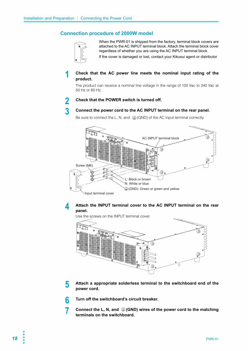
Connection procedure of 2000W modelWhen the PWR-01 is shipped from the factory, terminal block covers areattached to the AC INPUT terminal block. Attach the terminal block coverregardless of whether you are using the AC INPUT terminal block.If the cover is damaged or lost, contact your Kikusui agent or distributor
1 Check that the AC power line meets the nominal input rating of theproduct.The product can receive a nominal line voltage in the range of 100 Vac to 240 Vac at50 Hz or 60 Hz.
2 Check that the POWER switch is turned off.
3 Connect the power cord to the AC INPUT terminal on the rear panel. Be sure to connect the L, N, and (GND) of the AC input terminal correctly.
4 Attach the INPUT terminal cover to the AC INPUT terminal on the rearpanel. Use the screws on the INPUT terminal cover.
5 Attach a appropriate solderless terminal to the switchboard end of thepower cord.
6 Turn off the switchboard’s circuit breaker.
7 Connect the L, N, and (GND) wires of the power cord to the matchingterminals on the switchboard.
AC INPUT terminal block
Input terminal cover
N: White or blueL: Black or brown
(GND): Green or green and yellow
Screw (M6)

PWR-01 19
Load Considerations
Note that the output will become unstable if the following types of loads are connected.
Loads with peak current or pulse-shaped currentThe PWR-01 only indicates mean values. Even when the indicated value is less than or equalto the set constant current, the peak values may exceed the set constant current. If this hap-pens, the PWR-01 is instantaneously put into constant-current mode, and the output voltagedrops.For these types of loads, you must increase the set constant current or increase the currentcapacity.
Loads that generate reverse current to the power supplyThe PWR-01 cannot absorb reverse current from the load. Therefore, if a regenerative load(such as an inverter, converter, or transformer) is connected, the output voltage increasesand becomes unstable. This can cause a malfunction. For these types of loads, connect a resistor (RD) as shown in the following figure to bypassthe reverse current. However, the amount of current to the load decreases by Irp.
Load current with peaks Pulse-shaped load current
Constant current settingAmmeter reading (mean value)
Constant current settingAmmeter reading (mean value)
IO
RDEO
Equivalent circuit of the PWR-01 Regenerative load
0
Reverse current-IO
+IO
+
Irp
RD
RD: Reverse current bypass dummy loadEO: Output voltageIrp: Maximum reverse current
Load
Out
put c
urre
nt
CAUTION Use a resistor with sufficient rated power for RD. If a resistor with insufficient rated power for the circuit is used, resistor RD will burn out.

20 PWR-01
Installation and Preparation| Load Considerations
Loads with accumulated energyConnecting a load with accumulated energy, such as a battery, to the PWR-01 may causecurrent to flow from the load to the internal circuit of the PWR-01. This current may damagethe PWR-01 or reduce the life of the load.For this type of load, connect a reverse-current-prevention diode (DRP) between the PWR-01and the load in series as shown in the following figure.This cannot be used in conjunction with remote sensing.
This product Load with accumulated energy
DRP: Reverse-current-protection diodeDRP
CAUTION • To protect the load and the PWR-01, use a DRP that conforms to the following specifications. Reverse voltage withstand capacity: At least twice the rated output voltage of the PWR-01. Forward current capacity: 3 to 10 times the rated output current of the PWR-01. A diode with small loss.
• Be sure to take into account the heat generated by DRP. DRP will burn out with inadequate heat dissipation.

PWR-01 21
Selecting the Load Cables
Current capacity of load cablesA cable’s temperature is determined by the resistive loss based on the current, the ambienttemperature, and the cable’s external thermal resistance. The following table shows the cur-rent capacity of heat-resistant vinyl cables that have a maximum allowable temperature of60 °C when one of the cables is separated and stretched out horizontally in air in an ambienttemperature of 30 °C. The current must be reduced under certain conditions, such as whenvinyl cables that have a low heat resistance are used, when the ambient temperature is 30 °Cor greater, or when cables are bundled together and little heat is radiated.
Taking measures against noiseWhen connecting cables that have the same heat resistance, separating the cables as muchas possible to increase heat radiation enables a greater amount of current to flow. However,wiring the + (positive) and - (negative) output wires of the load cable side by side or bundlingthem together is more effective against unwanted noise. The Kikusui-recommended currentsshown in the above table are allowable currents that have been reduced in consideration ofthe potential bundling of load cables. Use these values as a guideline when connectingcables.
WARNING Risk of fire.• Use load cables whose capacity is adequate for the PWR-01’s rated output current.• The output terminal and its surrounding area become very hot. Use cables whose
covers have an allowable temperature of 85 °C or higher.Risk of electric shock.
• Use load cables with a voltage rating that meets or exceeds the product’s isolation voltage. For details on the PWR-01’s isolation voltage, see Chap.7 "Specifications"(p.123).
CAUTION • Use load cables with a core diameter that is appropriate for the amount of current being used and with sturdy, flame-resistant insulation.
Nominal cross-sectional area (mm2)
AWG (reference cross-sectional area; mm2)
Allowable current1(A)(Ta = 30 °C)
1 Excerpt from Japanese laws related to electrical equipment.
Kikusui-recom-mended current (A)
2 14 (2.08) 27 103.5 12 (3.31) 37 -5.5 10 (5.26) 49 208 8 (8.37) 61 3014 6 (13.3) 88 5022 4 (21.15) 115 8030 2 (33.62) 139 -38 1 (42.41) 162 10050 1/0 (53.49) 190 -60 2/0 (67.43) 217 -80 3/0 (85.01) 257 200100 4/0 (107.2) 298 -

22 PWR-01
Installation and Preparation| Selecting the Load Cables
Limitations of the remote sensing functionAll wires have resistance. As the wire becomes longer or the current becomes larger, the volt-age drop in the wire becomes greater. This results in a smaller voltage being applied at theload end. The PWR-01 has a sensing function that compensates for this voltage drop up tothe following values (p.34). If the voltage drop exceeds this level, use cables that have agreater cross-sectional area.
L type ML type MH type H type
Compensation voltage
Approx. 1.5 V one way
Approx. 4 V one way
Approx. 5 V one way
Approx. 5 V one way

PWR-01 23
Output Terminal Insulation
The cable and load that are connected to the output terminal (including the sensing terminal)must have an insulation capacity that is greater than or equal to the isolation voltage of thePWR-01 with respect to the chassis. Isolation voltage indicates the maximum allowed voltagethat appears across the output terminal of the power supply unit and the protective conductorterminal (chassis terminal).
When the output terminal is not grounded (floating)
The output terminal of the PWR-01 is isolated from the protective conductor terminal. If youconnect the GND wire of the power cord to the ground terminal of the switchboard, the chas-sis of the PWR-01 is set to ground potential.The J1 connector on the rear panel are at approximately the same electric potential as thePWR-01’s negative output terminal. Cables and devices that are connected to these pinsmust have an insulation capacity greater than or equal to the isolation voltage of the PWR-01.
WARNING Risk of electric shock. For safety reasons, even if the output terminal is grounded, make sure that the insulation capacity of the output terminal (including the sensing terminal) is greater than or equal to the isolation voltage of this product.For details on the isolation voltage of each model, see "Specifications" (p.123).If you cannot obtain a cable with sufficient rated voltage, secure adequate withstand voltage by passing the cable through an insulation tube with a withstand voltage greater than the isolation voltage of the PWR-01.
CAUTION The signal cable may burn out. If the PWR-01 is to be controlled through an external voltage (Vext), do not ground the external voltage (leave it floating).
+–
+
+S–S
–+–
16171819
1415
20
23456
13121110987
123456
1
ACINPUT
DCOUTPUT
J1 J2
SENS
LN
Load
Rext
PWR-01
Vext
Approximately the same electric potential as the negative output terminal
All pins of the J1 connector are at approximately the same electric potential as the PWR-01’s nega-tive output terminal.

24 PWR-01
Installation and Preparation| Output Terminal Insulation
When the output terminal is grounded
If the positive output terminal is connected to the chassis terminal, the positive output termi-nal is at ground potential. The cable and load that are connected to the output terminal(including the sensing terminal) will only require an insulation capacity that is greater than orequal to the maximum output voltage of the PWR-01 with respect to the chassis.The same holds true when the negative terminal is connected to the chassis terminal. Thecable and load require an insulation capacity that is greater than or equal to the maximumoutput voltage of the PWR-01.For safety reasons, connect one of the output terminals to the chassis terminal unless yourapplication requires the output terminals to be floating.
+–
+
+S–S
–+–
16171819
1415
20
23456
13121110987
123456
1
ACINPUT
DCOUTPUT
J1 J2
SENS
LN
Load
Rext
PWR-01
Vext
Chassis terminal
Approximately the same electric potential as the negative output terminalAll pins of the J1 connector are
at approximately the same elec-tric potential as the PWR-01’s negative output terminal.

PWR-01 25
Connecting to the Output Terminals
Tightening torque of output terminal connection screws
Connecting to the rear-panel output terminals
1 Turn the POWER switch off.Check that there is no residual voltage at the rear-panel output terminals.
2 Connect one end of the included chassis connection short bar to thechassis terminal and the other end to the negative or positive output ter-minal.
WARNING Risk of electric shock.• Turn the POWER switch off before you touch the rear-panel output terminals.• Even if you turn the output off or turn the POWER switch off, if the bleeder circuit is
set to off (CF01: DIS), the voltage that was present when the output was on will remain at the output terminals. Set the bleeder circuit to on (CF01: NORM/ HYP) before you touch the output terminals.
• Regardless of whether load cables are connected to the output terminals, be sure to attach the OUTPUT terminal cover before turning the POWER switch on.
Tightening torque [N・m]
M3 0.58
M4 1.33
M8 11.22
M10 22.47
Chassis terminal
800W model example

26 PWR-01
Installation and Preparation| Connecting to the Output Terminals
Bend the short bar to match the positions of the terminals.Use the screw on the PWR-01 to connect the short bar to the chassis terminal. Use thescrew on the rear-panel output terminal to connect the short bar to the output terminal.If you are not grounding the output terminal (leaving it floating), refer to “Output Termi-nal Insulation” (p.23) before use.
3 Attach solderless terminals to the load cables.The rear-panel output terminals have holes for connecting the load cables. Use sol-derless terminals that are appropriate for the bolts that you are using.
4 Connect the load cables to the rear-panel output terminals.Use the included screw set.To reduce the influence of noise on the output, keep the cables as short as possible. Ifpossible, twist the positive and negative load cables.
Chassis connection short bar
Screw (M3)
Screw (M3)Chassis connection short bar
Screw (M3)
Screw (M3)
400W modelExample of connecting to the negative terminal
2000W modelExample of connecting to the negative terminal
MemoIf you do not connect load cables in the correct orientation, you will not be able to attach the OUTPUT terminal cover.
Either side can be used.
Screw (M4)
Load cable
Screw (M4)
Load cable
Cable diameter Up to ø7 (including the insulation)
Applicable models 400W model 800W model 1200W model
400W model example 2000W model example
Cable diameter Up to ø10 (including the insulation)
Applicable models 2000W model
Bring the ring to the bottom side, and align to the top side of the output terminal.
[ Connection using the M4 screw set ]
PWR-01 27
Installation and Preparation| Connecting to the Output Terminals
Attaching the OUTPUT terminal cover
You can adjust the diameter of the holes that the load cables pass through by changing theorientation of the adapter attached to the OUTPUT terminal cover. There are two availableorientations. Use the appropriate orientation for the load cables (including the insulation) thatyou are using.
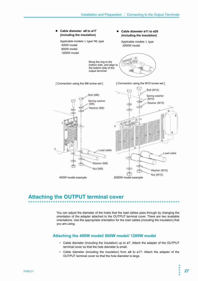
Attaching the 400W model/ 800W model/ 1200W model• Cable diameter (including the insulation) up to ø7: Attach the adapter of the OUTPUT
terminal cover so that the hole diameter is small.• Cable diameter (including the insulation) from ø8 to ø17: Attach the adapter of the
OUTPUT terminal cover so that the hole diameter is large.
Cable diameter ø8 to ø17(including the insulation)
Applicable models: L type/ ML type 400W model 800W model 1200W model
Cable diameter ø11 to ø20(including the insulation)
Applicable models: L type 2000W model
[ Connection using the M8 screw set ] [ Connection using the M10 screw set ]
Bring the ring to the bottom side, and align to the bottom side of the output terminal.
Spring washer (M8)Washer (M8)
Washer (M8)
Nut (M8)
Bolt (M8) Spring washer (M10)Washer (M10)
Bolt (M10)
Load cable
Washer (M10)Nut (M10)
Load cable
400W model example 2000W model example
28 PWR-01
Installation and Preparation| Connecting to the Output Terminals
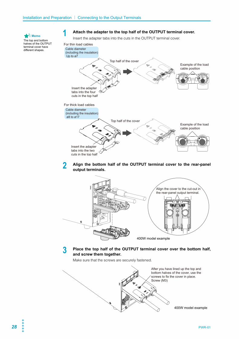
1 Attach the adapter to the top half of the OUTPUT terminal cover.Insert the adapter tabs into the cuts in the OUTPUT terminal cover.
2 Align the bottom half of the OUTPUT terminal cover to the rear-paneloutput terminals.
3 Place the top half of the OUTPUT terminal cover over the bottom half,and screw them together.Make sure that the screws are securely fastened.
MemoThe top and bottom halves of the OUTPUT terminal cover have different shapes.
Top half of the cover
For thin load cables
Cable diameter (including the insulation) ø8 to ø17
Cable diameter (including the insulation) Up to ø7
For thick load cables
Top half of the cover
Example of the load cable position
Example of the load cable position
Insert the adapter tabs into the two cuts in the top half
Insert the adapter tabs into the four cuts in the top half
Align the cover to the cut-out in the rear-panel output terminal.
400W model example
After you have lined up the top and bottom halves of the cover, use the screws to fix the cover in place.Screw (M3)
400W model example

PWR-01 29
Installation and Preparation| Connecting to the Output Terminals
Attaching the 2000W model• Cable diameter (including the insulation) up to ø10: Attach the adapter of the OUTPUT
terminal cover so that the hole diameter is small.• Cable diameter (including the insulation) from ø11 to ø20: Attach the adapter of the
OUTPUT terminal cover so that the hole diameter is large.
1 Attach the adapter to the top half of the OUTPUT terminal cover.Insert the adapter in alignment with the tabs or cuts in the OUTPUT terminal cover.
Rear view
Top half of the cover
Top half of the cover
For thin load cablesCable diameter (including the insulation)Up to ø10
Cable diameter (including the insulation) ø11 to ø20
For thick load cables
Example of the load cable position
Example of the load cable position
Insert the adapter tabs into the two cuts in the top half
Insert the adapter cuts into the three tabs in the top half

30 PWR-01
Installation and Preparation| Connecting to the Output Terminals
2 Align the bottom half of the OUTPUT terminal cover to the rear-paneloutput terminals.
3 Place the top half of the OUTPUT terminal cover recessed slightly on topof the bottom half, and then slide it forward. Use the screws on the top half to secure them in place.Make sure that the screws are securely fastened.
Place the top half recessed slightly on top of the bottom half ( ) and then slide ( ).
After you have lined up the top and bottom halves of the cover, use the screws to fix the cover in place.Screw (M3)
1
1
2
2

PWR-01 31
Installation and Preparation| Connecting to the Output Terminals
Connecting to the front-panel output terminals
The specifications of the PWR-01 apply to the rear-panel output terminals. The front-paneloutput terminals may not meet the specifications.There is no grounding terminal on the front-panel output terminals. To ground one side of theoutput, connect the rear-panel chassis terminal to either the negative output terminal or thepositive output terminal.If you are not grounding the output terminal (leaving it floating), refer to “Output TerminalInsulation” (p.23) before use.
If the output current of the front-panel output terminals exceeds 10 A (typical value), the front-panel output terminal overcurrent protection (FOCP) will be activated (p.55).
Necessary cables and plugs (recommended)
Polyvinyl chloride insulation cable: Nominal cross-sectional area of 0.33 mm2 (AWG22) to0.82 mm2 (AWG18)Rated voltage: 1000 V or higherLength: Less than 3 mOutput terminal plugs: Safety plugs
Safety plugs TL41 and TL42 are available as options (p.147).
1 Attach safety plugs to the load cables.
2 Connect the load cables with safety plugs to the front-panel output ter-minals.To reduce the influence of noise on the output, keep the cables as short as possible.Twist the positive and negative load cables.
WARNING • Risk of electric shock. The front-panel output terminals are designed to be used with safety plugs. Do not use connectors that have bare conductive parts (such as banana plugs) to connect to the front-panel output terminals.
• Risk of heat buildup or fire.Do not run current higher than 10 A through the front-panel output terminals.
Front-panel output terminal.
- (negative) terminal
+ (positive) terminal
Safety plugs 800W model example
32 PWR-01
Turning the Power On
Turning on the POWER switch
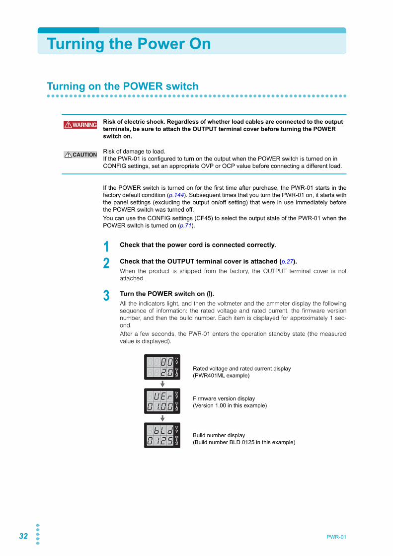
If the POWER switch is turned on for the first time after purchase, the PWR-01 starts in thefactory default condition (p.144). Subsequent times that you turn the PWR-01 on, it starts withthe panel settings (excluding the output on/off setting) that were in use immediately beforethe POWER switch was turned off.You can use the CONFIG settings (CF45) to select the output state of the PWR-01 when thePOWER switch is turned on (p.71).
1 Check that the power cord is connected correctly.
2 Check that the OUTPUT terminal cover is attached (p.27).When the product is shipped from the factory, the OUTPUT terminal cover is notattached.
3 Turn the POWER switch on ( ).All the indicators light, and then the voltmeter and the ammeter display the followingsequence of information: the rated voltage and rated current, the firmware versionnumber, and then the build number. Each item is displayed for approximately 1 sec-ond.After a few seconds, the PWR-01 enters the operation standby state (the measuredvalue is displayed).
WARNING Risk of electric shock. Regardless of whether load cables are connected to the output terminals, be sure to attach the OUTPUT terminal cover before turning the POWER switch on.
CAUTION Risk of damage to load.If the PWR-01 is configured to turn on the output when the POWER switch is turned on in CONFIG settings, set an appropriate OVP or OCP value before connecting a different load.
Firmware version display(Version 1.00 in this example)
Rated voltage and rated current display(PWR401ML example)
Build number display(Build number BLD 0125 in this example)
CV
CC
/W
V
A
CV
CC
/W
V
A
CV
CC
/W
V
A
CV
CC
/W
V
A
CV
CC
/W
V
A
CV
CC
/W
V
A
PWR-01 33
Installation and Preparation| Turning the Power On
Turning the POWER switch off
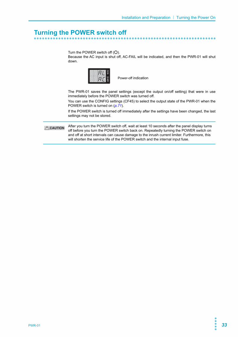
Turn the POWER switch off ( ).Because the AC input is shut off, AC-FAIL will be indicated, and then the PWR-01 will shutdown.
The PWR-01 saves the panel settings (except the output on/off setting) that were in useimmediately before the POWER switch was turned off.You can use the CONFIG settings (CF45) to select the output state of the PWR-01 when thePOWER switch is turned on (p.71).If the POWER switch is turned off immediately after the settings have been changed, the lastsettings may not be stored.
Power-off indication
CV
CC
/W
V
A
CV
CC
/W
V
A
CAUTION After you turn the POWER switch off, wait at least 10 seconds after the panel display turns off before you turn the POWER switch back on. Repeatedly turning the POWER switch on and off at short intervals can cause damage to the inrush current limiter. Furthermore, this will shorten the service life of the POWER switch and the internal input fuse.

34 PWR-01
Remote Sensing function
Remote sensing is a function that stabilizes the output voltage across the load by reducingthe influence of voltage drops and other effects caused by the load cable resistance.The PWR-01 remote sensing can compensate up to the values shown below. Select a loadcable that has sufficient current capacity to prevent the voltage drop in the load cable fromexceeding the compensation voltage.When you perform remote sensing, set the voltage of the sensing point (across the load) sothat it does not exceed the rated output voltage. If you are performing remote sensing withthe voltage close to the maximum output voltage, the output is limited by the maximum outputvoltage (105 % of the rated output voltage). Electrolytic capacitors may be required at thesensing point (across the load).To reduce the effect of noise, use twisted-pair cables or 2-core shielded cables. When youuse shielded cables, connect the shield to the PWR-01 or the load grounding terminal.
When the product is shipped from the factory, a sensing short baris connected across the sensing terminals and DC OUTPUT termi-nals. When the sensing terminals are not used, connect the sens-ing short bar.If the short bar is damaged or lost, contact your Kikusui agent ordistributor.
Connecting the sensing cables
L type ML type MH type H type
Compensation voltage
Approx. 1.5 V one way
Approx. 4 V one way
Approx. 5 V one way
Approx. 5 V one way
E3-200-546
WARNING Risk of electric shock and damage to internal circuits.• Never wire the sensing terminals while the POWER switch is turned on.• For sensing cables, use cables with a voltage rating that is higher than the PWR-01’s
isolation voltage. Protect the uncovered sections of the shielded cable by using insulation tubes whose withstand voltage is greater than the PWR-01’ isolation volt-age.
• Even if you turn the output off or turn the POWER switch off, if the bleeder circuit is set to off (CF01: DIS), the voltage that was present when the output was on will remain at the output terminals. Set the bleeder circuit to on (CF01: NORM/ HYP) before you touch the sensing terminals.
• Be sure to attach the OUTPUT terminal cover before turning the POWER switch on.

PWR-01 35
Installation and Preparation| Remote Sensing function
If the sensing cables come loose, the output voltage will rise several volts. To prevent voltageoutput exceeding the voltage setting, set an appropriate OVP trip point.
After you finish using remote sensing, connect the sensing short bar.
1 Turn the POWER switch off.
2 Remove the sensing short bar that is connected across the sensing ter-minals and DC OUTPUT terminals.
3 Attach Solderless terminals to the sensing cables, and connect thesensing terminals to the sensing point (across the load).Attach Solderless terminals that match the screws to be used, and securely fasten thecables.If you cannot use shielded cables, twist the positive and negative cables sufficiently.
++
––
Capacitor
+S
-S
Connect an electrolytic capacitor across the
Output terminal
Chassis terminal
Sensing terminal
PWR-01
Load
Shielded cable
Sensing short bar
Screw (M3x6)
400W model example
36 PWR-01
Installation and Preparation| Remote Sensing function
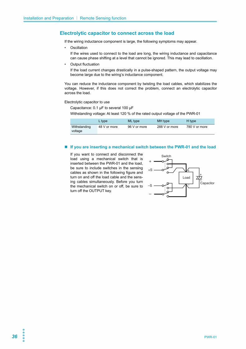
Electrolytic capacitor to connect across the loadIf the wiring inductance component is large, the following symptoms may appear.• Oscillation
If the wires used to connect to the load are long, the wiring inductance and capacitancecan cause phase shifting at a level that cannot be ignored. This may lead to oscillation.
• Output fluctuationIf the load current changes drastically in a pulse-shaped pattern, the output voltage maybecome large due to the wiring’s inductance component.
You can reduce the inductance component by twisting the load cables, which stabilizes thevoltage. However, if this does not correct the problem, connect an electrolytic capacitoracross the load.
Electrolytic capacitor to useCapacitance: 0.1 µF to several 100 µFWithstanding voltage: At least 120 % of the rated output voltage of the PWR-01
If you are inserting a mechanical switch between the PWR-01 and the loadIf you want to connect and disconnect theload using a mechanical switch that isinserted between the PWR-01 and the load,be sure to include switches in the sensingcables as shown in the following figure andturn on and off the load cable and the sens-ing cables simultaneously. Before you turnthe mechanical switch on or off, be sure toturn off the OUTPUT key.
L type ML type MH type H type
Withstanding voltage
48 V or more 96 V or more 288 V or more 780 V or more
Load
Switch
+
–Capacitor
+
–
+S
–S
+
–

Basic FeaturesThis chapter describes how to turn theoutput on and off and the basic operationsthat you can perform from the front panel.
38 PWR-01
Measured Value Display and Setting Display
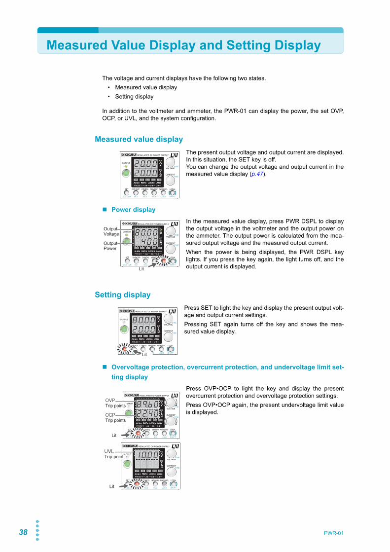
The voltage and current displays have the following two states.• Measured value display• Setting display
In addition to the voltmeter and ammeter, the PWR-01 can display the power, the set OVP,OCP, or UVL, and the system configuration.
Measured value displayThe present output voltage and output current are displayed.In this situation, the SET key is off.You can change the output voltage and output current in themeasured value display (p.47).
Power displayIn the measured value display, press PWR DSPL to displaythe output voltage in the voltmeter and the output power onthe ammeter. The output power is calculated from the mea-sured output voltage and the measured output current.When the power is being displayed, the PWR DSPL keylights. If you press the key again, the light turns off, and theoutput current is displayed.
Setting displayPress SET to light the key and display the present output volt-age and output current settings.Pressing SET again turns off the key and shows the mea-sured value display.
Overvoltage protection, overcurrent protection, and undervoltage limit set-ting display
Press OVP•OCP to light the key and display the presentovercurrent protection and overvoltage protection settings.Press OVP•OCP again, the present undervoltage limit valueis displayed.
CV
CC
/W
V
A
ALM RMT LOCK LAN
B CAPRESET
DLY SEQ HBSSVIR
CV
CC
/W
V
A
ALM RMT LOCK LAN
SC2 SC3 LOCKALM CLR SC1 SHIFT
FINE
FINE
REGULATED DC POWER SUPPLY
OUTPUT
VOLTAGE
CURRENT
CONFIG PWR DSPLMEMORY LOCALSET OVP•OCP
CV
CC
/W
V
A
ALM RMT LOCK LAN
B CAPRESET
DLY SEQ HBSSVIR
CV
CC
/W
V
A
ALM RMT LOCK LAN
SC2 SC3 LOCKALM CLR SC1 SHIFT
FINE
FINE
REGULATED DC POWER SUPPLY
OUTPUT
VOLTAGE
CURRENT
CONFIG PWR DSPLMEMORY LOCALSET OVP•OCP
Lit
OutputPower
OutputVoltage
CV
CC
/W
V
A
ALM RMT LOCK LAN
B CAPRESET
DLY SEQ HBSSVIR
CV
CC
/W
V
A
ALM RMT LOCK LAN
SC2 SC3 LOCKALM CLR SC1 SHIFT
FINE
FINE
REGULATED DC POWER SUPPLY
OUTPUT
VOLTAGE
CURRENT
CONFIG PWR DSPLMEMORY LOCALSET OVP•OCP
Lit
CV
CC
/W
V
A
ALM RMT LOCK LAN
B CAPRESET
DLY SEQ HBSSVIR
CV
CC
/W
V
A
ALM RMT LOCK LAN
SC2 SC3 LOCKALM CLR SC1 SHIFT
FINE
FINE
REGULATED DC POWER SUPPLY
OUTPUT
VOLTAGE
CURRENT
CONFIG PWR DSPLMEMORY LOCALSET OVP•OCP
Lit
OCPTrip points
OVPTrip points
CV
CC
/W
V
A
ALM RMT LOCK LAN
B CAPRESET
DLY SEQ HBSSVIR
CV
CC
/W
V
A
ALM RMT LOCK LAN
SC2 SC3 LOCKALM CLR SC1 SHIFT
FINE
FINE
REGULATED DC POWER SUPPLY
OUTPUT
VOLTAGE
CURRENT
CONFIG PWR DSPLMEMORY LOCALSET OVP•OCP
Lit
Trip point

PWR-01 39
Basic Features| Measured Value Display and Setting Display
System configuration setting displayPress CONFIG to light the key and display the current systemconfiguration settings.CV
CC
/W
V
A
ALM RMT LOCK LAN
B CAPRESET
DLY SEQ HBSSVIR
CV
CC
/W
V
A
ALM RMT LOCK LAN
SC2 SC3 LOCKALM CLR SC1 SHIFT
FINE
FINE
REGULATED DC POWER SUPPLY
OUTPUT
VOLTAGE
CURRENT
CONFIG PWR DSPLMEMORY LOCALSET OVP•OCP
Lit

40 PWR-01
Panel Operations
Measured value display, setting display, and set OVP/ OCP displayTurn the VOLTAGE knob to change the voltage. Turn theCURRENT knob to change the current.When the output is on, press SET to switch to the setting dis-play, and then change the output while you view the actualvoltage or current settings.
Fine adjustment (FINE)Hold down SHIFT while you turn the VOLTAGE knob or CURRENT knob to make smallchanges to the value. When the output is on, amount of change becomes even smaller.The displayed current or voltage may not change even if you turn the VOLTAGE or CUR-RENT knob. This is because the value is being changed at a higher resolution than what isshown. In this situation, the display will change when the amount that you change the valueby reaches the smallest display digit of the set voltage or current.
CV
CC
/W
V
A
ALM RMT LOCK LAN
B CAPRESET
DLY SEQ HBSSVIR
CV
CC
/W
V
A
ALM RMT LOCK LAN
SC2 SC3 LOCKALM CLR SC1 SHIFT
FINE
FINE
REGULATED DC POWER SUPPLY
OUTPUT
VOLTAGE
CURRENT
CONFIG PWR DSPLMEMORY LOCALSET OVP•OCP
IncreaseDecrease
IncreaseDecrease

PWR-01 41
Output Operation
The output turns on and off each time that you press OUTPUT. When output is on, the OUT-PUT LED lights. When the output is off, the OUTPUT LED turns off.When the output is on, output is generated at the present set values.If you change the settings while the output is on, the changes are applied immediately to theoutput. If the output is off, the setting display will appear (the SET key lights) as soon as youchange the settings. After changing the setting, pressing OUTPUT turns the output on.
You can use external control to turn the output on and off (p.67, p.100).
Setting limitsYou can apply limits to the voltage and current settings (p.52, p.54, p.59).Using CONFIG settings (CF22/ CF23), you can set limitations so that the values do notexceed about 95 % of the set overvoltage protection (OVP) trip point or about 95 % of the setovercurrent protection (OCP) trip point and so that the values are not set lower than the setundervoltage limit (UVL trip point).You can avoid turning the output off by mistakenly setting the voltage or current to a valuethat exceeds the set OVP or OCP trip point or avoid setting a value that is lower than the setUVL trip point.
Output on/off setting at power-on
By factory default, the output is off when the power is turned on. Using a CONFIG setting, youcan set the output state at power-on (p.71).
About 2000W model, the breaker trip setting that is applied when an OVP/ OCP/ FOCP/ SDor PRL ALM activates is set to “trip” (CF25: ON) and the OVP trip point is set lower than theoutput voltage setting, the OVP will activate every time you turn the POWER switch on andthe POWER switch will turn off. If the condition above occurs and you are unable to change any of the settings, turn off the on/ off control setting of the external control output, turn the POWER switch, and change theOVP trip point. Or, on while holding down the LOCAL key and PWR DSPL key to reset thePWR-01 to factory default settings (p.100, p.144).
CV
CC
/W
V
A
ALM RMT LOCK LAN
B CAPRESET
DLY SEQ HBSSVIR
CV
CC
/W
V
A
ALM RMT LOCK LAN
SC2 SC3 LOCKALM CLR SC1 SHIFT
FINE
FINE
REGULATED DC POWER SUPPLY
OUTPUT
VOLTAGE
CURRENT
CONFIG PWR DSPLMEMORY LOCALSET OVP•OCP
Lit
CAUTION If the output is set so that it is on at power-on, be sure to check the OVP and OCP trip point settings (p.52, p.53) before you turn off the POWER switch. If the OVP or OCP trip point is not set properly when the load is changed, the load could be damaged.
42 PWR-01
Basic Features| Output Operation
Output-on startup state parameter
You can set whether to start the PWR-01 as a constant voltage (CV) power supply or a con-stant current (CC) power supply when the output is turned on (p.64).Using the output-on startup state CONFIG parameter (CF02: CV/CC), select prioritize CV(CF02: CV) to start as a constant voltage (CV) power supply or prioritize CC (CF02: CC) tostart as a constant current (CC) power supply.
Output-on/ off delay setting
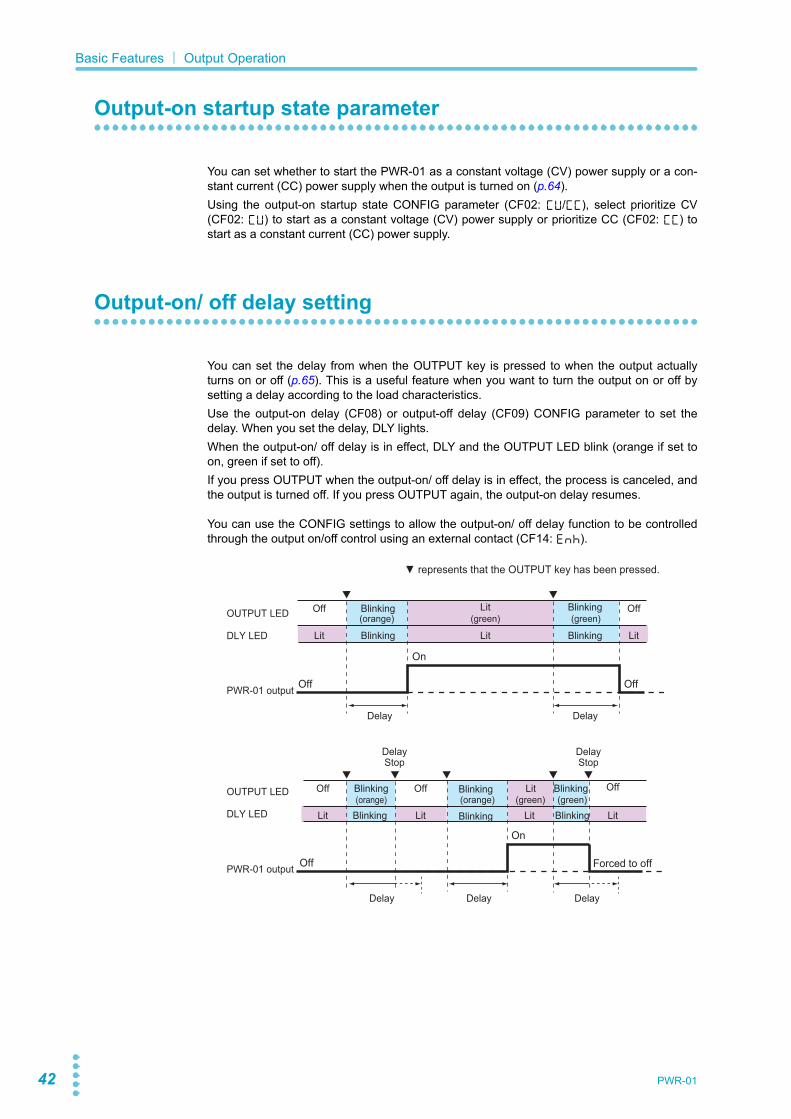
You can set the delay from when the OUTPUT key is pressed to when the output actuallyturns on or off (p.65). This is a useful feature when you want to turn the output on or off bysetting a delay according to the load characteristics.Use the output-on delay (CF08) or output-off delay (CF09) CONFIG parameter to set thedelay. When you set the delay, DLY lights.When the output-on/ off delay is in effect, DLY and the OUTPUT LED blink (orange if set toon, green if set to off).If you press OUTPUT when the output-on/ off delay is in effect, the process is canceled, andthe output is turned off. If you press OUTPUT again, the output-on delay resumes.
You can use the CONFIG settings to allow the output-on/ off delay function to be controlledthrough the output on/off control using an external contact (CF14: ENH).
Off OffBlinking Lit Blinking
Lit LitBlinking Lit Blinking
DelayDelay
Delay
OffLitBlinking
On
(orange)
(orange)(orange)
(green)
(green) (green)
(green)
Off Off
Forced to off
OUTPUT LED
DLY LED
PWR-01 output
PWR-01 output
OUTPUT LED
DLY LED
Delay Delay
Off OffBlinking Blinking
LitLitBlinkingLit LitBlinking Blinking
On
Off
DelayStop
DelayStop

PWR-01 43
Basic Features| Output Operation
Soft start/ soft stop function
You can set the rise time and fall time of output voltage/ output current.This is useful when the load cannot follow the sudden rise or fall in the output voltage/ outputcurrent or when you want to avoid the overvoltage protection/ overcurrent protection frombeing activated.Set the soft start time (CF04/ CF06) and soft stop time (CF05/ CF07) CONFIG parameters.The soft start and soft stop times are applied to the operation mode set by the output-onstartup state (CF02: CV/ CC).When you set the this function, SS lights.When soft start is in effect, SS blinks, and the OUTPUT LED lights green.When soft stop is in effect, SS and the OUTPUT LED blink green.If you press OUTPUT when soft start or soft stop is in effect, the process is canceled, and theoutput is turned off. If you press OUTPUT again, soft start resumes.
If the bleeder circuit is set to off, the output current may not fall gradually even if soft stop isused.
You can use the CONFIG settings to allow the soft start and soft stop functions to be con-trolled through the output on/off control using an external contact (CF14: ENH).
0.1s 0.1s 0.1s
Actually, each transition takes place over 0.1 s.
Blinking OffLit
LitLitLit
LitLitBlinking
OffBlinking Blinking
OffLit
OffLit
OffLitBlinking Blinking
LitLitLit
Blinking
On
Off Off
Soft stop timeSoft start time
Soft startcanceled
Soft stopcanceled
OUTPUT LED
SS LED
OUTPUT LED
SS LED
PWR-01 output
PWR-01 output
Soft stop timeSoft starttime
Soft start time
Forced to offOff
On

44 PWR-01
Basic Features| Output Operation
Soft start and soft stop waveformsWaveforms when soft start and soft stop are used are shown below.
Waveform when soft start is used
Waveform when soft stop is used
5.00
0
5
5.0 10.0[Time (s)]
[Voltage (V)]
off
Outpu on: Output voltage 5 VSoft start time: 5.0 s (CF06: 5.0)
5.00
0
5
5.0 10.0[Time (s)]
[Voltage (V)]
Outputon
Outputoff
Outpt off: Output voltage 5 VSoft stop time: 5.0 s(CF07: 5.0 s)

PWR-01 45
Operation Overview
The PWR-01 is a constant voltage (CV)/ constant current (CC) regulated DC power supplythat can output a wide range of voltage and current within rated output power.If you configure the settings so that "output voltage × output current" is less than or equal tothe rated output power, the PWR-01 operates as a traditional constant-voltage (CV)/ con-stant-current (CC) power supply.If you configure the settings so that "output voltage × output current" is greater than the ratedoutput power, the actual output is limited (p.59) by the power limit (POWER LIMIT: approxi-mately 105 % of the rated output power), and the output voltage and output current changedepending on the load value.
Output current (A)
Out
put v
olta
ge (V
)
35
30
45
40
2520
15
10
5
00 5 10 15 20 25 30 45
0 10 20 30 40 50 60
35
70
40
80 90
0 15 30 45 60 75 90 105 120 135
0 25 50 75 100 125 150 175 200 225
Rated output current
Rated output powerRated output power
[L type] Operating rangeRated output voltage: 40 V
PWR401L
PWR801L
PWR1201L
PWR2001L
PWR401L: 400 WPWR801L: 800 WPWR1201L: 1200 WPWR2001L: 2000 W
Output current (A)
Out
put v
olta
ge (V
)
60
30
90
40
80
70
20
50
10
00 2.5 5 7.5 10 12.5 15 22.5
0 5 10 15 20 25 30
17.5
35
20
40 45
0 7.5 15 22.5 30 37.5 45 52.5 60 67.5
Rated output current
Rated output powerRated output power
[ML type] Operating rangeRated output voltage: 80 V
PWR401ML
PWR801ML
PWR1201ML
PWR401ML: 400 WPWR801ML: 800 WPWR1201ML: 1200 W

46 PWR-01
Basic Features| Operation Overview
Out
put v
olta
ge (V
) 300
250
200
50
150
100
00 0.5 1 2.5 3 4
0 1 2
1.5
3 5
2
4 6
3.5
7 8
4.5
9
5
10
5.5
11
Output current (A)0 1.5 3 4.5 7.56 9 10.5 12 13.5 15 16.5
Rated output current
Rated output power
Rated output powerRated output voltage: 240 V
PWR401MH
PWR801MH
PWR1201MH
[MH type] Operating range
PWR401MH: 400 WPWR801MH: 800 WPWR1201MH: 1200 W
Out
put v
olta
ge (V
) 700
600
500
100
200
400
300
00 0.2 0.4 1 1.2 1.6
0 0.4 0.8
0.6
1.2 2
0.8
1.6 2.4
1.4
2.8 3.2
1.8
3.6
2
4
Output current (A)0 0.6 1.2 1.8 32.4 3.6 4.2 4.8 5.4 6
Rated output current
Rated output powerRated output power
Rated output voltage: 650 V
PWR401H
PWR801H
PWR1201H
[H type] Operation range
PWR401H: 400 WPWR801H: 800 WPWR1201H: 1200 W

PWR-01 47
CV Power Supply and CC Power Supply
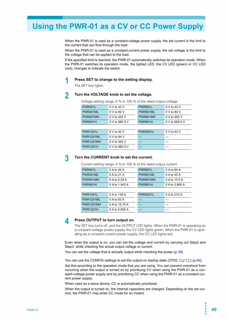
The PWR-01 has features that makes it possible to function as a constant-voltage source andconstant-current source even when the load is changed. The constant-voltage source opera-tion is referred to as constant-voltage (CV) mode. The constant-current source operation isreferred to as constant-current (CC) mode. The operation mode is determined by the follow-ing three values.
• Output voltage setting (Vs)
• Output current setting (Is)
• Load resistance (RL)The operation modes are described below.
The above figure shows the PWR-01 operation modes. The load resistance is denoted as RL.The resistance, which is denoted as Rc, is calculated from the set voltage and current (Rc =Vs/ Is. Resistance at the crossover point). The power supply is designed so that it operates inCV mode in area and CC mode in area . The boundary is the line defined by RL = Rc.This line represents the load at which the output voltage and the set voltage are equal andthe output current and the set current are equal. If load resistance RL is greater than resis-tance RC, the operating point is in area , and the PWR-01 operates in CV mode (point p).In this case, the set current Is equals the current limit.When the PWR-01 is operating in CV mode, the output voltage is maintained at the set volt-age. Output current I is determined by the equation I = Vs/RL and is a current that is less thancurrent limit Is. The actual current that flows is not necessarily equal to the specified value.For loads in which transient peak current flows, current limit Is must be set higher than thepeak value.
Conversely, if load resistance RL is less than resistance Rc, the operating point is in area ,and the PWR-01 operates in CC mode (point q). In this case, set voltage Vs equals the volt-age limit.When the PWR-01 is operating in CC mode, the output current is maintained at the set cur-rent. Output voltage V is determined by the equation V = Is x RL and is a voltage that is lessthan voltage limit Vs. The actual voltage that is applied is not necessarily equal to the speci-fied value.
Crossover pointThe PWR-01 switches automatically between CV mode and CC mode according to thechanges in the load. A crossover point is the point at which the mode switches.For example, when operating in CV mode, if the load changes and the output current reachesthe current limit, the PWR-01 automatically switches to CC mode to protect the load. Like-wise, when operating in CC mode, if the output voltage reaches the voltage limit, the PWR-01switches to CV mode.
0 ImaxIs
VsVmax
Output current Iout
Crossover point
A = CV mode area B = CC mode area
Vs = Set voltageIs = Set currentRc = Vs/ Is (Ohm’s Law)RL = Load resistanceVmax = Maximum settable voltageImax = Maximum settable current
RL = RcRL > Rc
RL < Rc
p
q
A
B
Out
put
volt
age
Vou
t
A B
A
B

48 PWR-01
Basic Features| CV Power Supply and CC Power Supply
CV mode and CC mode operation exampleThis section uses a power supply with a rated output voltage of 100 V and a rated output cur-rent of 10 A as an example.A load resistance (RL) of 8 Ω is connected to the output terminals of the power supply. Theoutput voltage and output current are set to 30 V and 5 A, respectively. In this case, Rc =30 V/ 5 A = 6 Ω. Because 8 Ω is greater than 6 Ω (RL > Rc), the power supply operates in CVmode. When you want to increase the voltage in CV mode, you can increase the voltage upto the voltage defined by the following equation: Vs = Is × RL. Substituting the values, weobtain Vs = 5 A × 8 Ω = 40 V. If you try to increase the voltage above this point, the crossoverpoint is reached, and the power supply automatically switches to CC mode. To maintain oper-ations in CV mode, increase the current limit.Next, a load resistance (RL) of 5 Ω is connected to the output terminals of the power supply.The output voltage and output current are set to 30 V and 5 A, respectively. In this case, Rc =30 V/ 5 A = 6 Ω. Because 5 Ω is less than 6 Ω (RL < Rc), the power supply operates in CCmode. If you want to increase the current in CC mode, you can increase the current up to thecurrent defined by the following equation: Is = Vs/RL. Substituting the values, we obtain Is =30 V/5 Ω = 6 A. If you try to increase the current above this point, the crossover point isreached, and the power supply automatically switches to CV mode. To maintain operations inCC mode, increase the voltage limit.
PWR-01 49
Using the PWR-01 as a CV or CC Power SupplyWhen the PWR-01 is used as a constant-voltage power supply, the set current is the limit tothe current that can flow through the load.When the PWR-01 is used as a constant-current power supply, the set voltage is the limit tothe voltage that can be applied to the load.If the specified limit is reached, the PWR-01 automatically switches its operation mode. Whenthe PWR-01 switches its operation mode, the lighted LED, the CV LED (green) or CC LED(red), changes to indicate the switch.
1 Press SET to change to the setting display.The SET key lights.
2 Turn the VOLTAGE knob to set the voltage.
Voltage setting range: 0 % to 105 % of the rated output voltage
3 Turn the CURRENT knob to set the current.
Current setting range: 0 % to 105 % of the rated output current
4 Press OUTPUT to turn output on.The SET key turns off, and the OUTPUT LED lights. When the PWR-01 is operating asa constant-voltage power supply, the CV LED lights green. When the PWR-01 is oper-ating as a constant-current power supply, the CC LED lights red.
Even when the output is on, you can set the voltage and current by carrying out Step2 andStep3 while checking the actual output voltage or current.You can set the voltage that is actually output while checking the power (p.38).
You can use the CONFIG settings to set the output-on startup state (CF02: CV/ CC) (p.64).Set this according to the operation mode that you are using. You can prevent overshoot fromoccurring when the output is turned on by prioritizing CV when using the PWR-01 as a con-stant-voltage power supply and by prioritizing CC when using the PWR-01 as a constant-cur-rent power supply.When used as a slave device, CC is automatically prioritized.When the output is turned on, the internal capacitors are charged. Depending on the set cur-rent, the PWR-01 may enter CC mode for an instant.
PWR401L 0 V to 42 V PWR801L 0 V to 42 VPWR401ML 0 V to 84 V PWR801ML 0 V to 84 VPWR401MH 0 V to 252 V PWR801MH 0 V to 252 VPWR401H 0 V to 682.5 V PWR801H 0 V to 682.5 V
PWR1201L 0 V to 42 V PWR2001L 0 V to 42 VPWR1201ML 0 V to 84 V — —PWR1201MH 0 V to 252 V — —PWR1201H 0 V to 682.5 V — —
PWR401L 0 A to 42 A PWR801L 0 A to 84 APWR401ML 0 A to 21 A PWR801ML 0 A to 42 APWR401MH 0 A to 5.25 A PWR801MH 0 A to 10.5 APWR401H 0 A to 1.943 A PWR801H 0 A to 3.885 A
PWR1201L 0 A to 126 A PWR2001L 0 A to 210 APWR1201ML 0 A to 63 A — —PWR1201MH 0 A to 15.75 A — —PWR1201H 0 A to 5.828 A — —

50 PWR-01
Protection functionsThe PWR-01 protection functions can be divided into those that shut off the output and thosethat limit settings.
Output shutoff (Alarm occurrence)• Overvoltage protection (OVP) • Overcurrent protection (OCP)• Front-panel output terminal overcurrent protection (FOCP)• Overheat protection (OHP)• Incorrect sensing connection protection (SENSE)• Low AC input protection (AC-FAIL)• Communication monitoring (WATCHDOG) • Shutdown (SD)• Master-slave parallel operation protection (PRL ALM)
Setting limits• Voltage setting limit (limited to about 95 % of the OVP trip point)• Undervoltage limit (UVL)• Current setting limit (limited to about 95 % of the OCP trip point)• Power limit (POWER LIMIT)
Alarm occurrence and clearing alarms
Alarm occurrenceWhen a protection function is activated and the output is shut off, an alarm occurs, and thePWR-01 is set to the following state.• Output off
For the OVP/ OCP/ FOCP/ SD/ PRL ALM activation, you can select breaker tripping usingCONFIG settings (2000W model only).
• ALM LED on, indication of the cause of alarmOUTPUT LED blinking orange if the protection function was activated when the outputwas onWhen a CONFIG parameter is being displayed, the cause of alarm is not displayed.If breaker tripping is selected for OVP/ OCP/ FOCP/ SD/ PRL ALM (CF25: ON),indications of the cause of alarm and low AC input protection (AC-FAIL) are shownalternately on the front panel display (2000W model only).
• Alarm signal outputAlarm signal generated from pin 14 of the J1 connector if PRL ALM or SD is activatedAlarm signal generated from pin 4 of the J2 connector if OVP, OCP, FOCP, OHP, SENSE,AC-FAIL, WATCHDOG, or SD is activatedEven when the breaker trips, an alarm signal is output (2000W model only).

PWR-01 51
Basic Features| Protection functions
Clearing alarmsThere are two methods to clear alarms.a. Press ALM CLR (SHIFT+SET) or apply a low level signal (0 V to 0.5 V) to or short pin 6 of
the J1 connector to clear the alarm state. If you do not eliminate the cause of the alarm,an alarm will occur again.
b. Turn off the POWER switch. Fix the problem that caused the alarm, and turn the POWERswitch back on.
For low AC input protection (AC-FAIL), shutdown (SD) and master-slave parallel operation(PRL ALM), use method “b” to clear the alarm.
If an alarm still occurs even after you have corrected all the causes of alarms, the PWR-01may be malfunctioning. Stop using it immediately, and contact your Kikusui agent or distribu-tor.
Alarm signalAlarm signal is generated from pin 14 of the J1 connector if PRL ALM or SD is activated. TheJ1 connector is at approximately the same electric potential as the negative output terminal.Alarm signal is generated from pin 4 of the J2 connector if OVP, OCP, FOCP, OHP, SENSE,AC-FAIL, WATCHDOG, or SD is activated. The signal is isolated from other terminals throughan open collector photocoupler.
Maximum voltage: 30 VMaximum current: 8 mA
4
1
J2 connector
ALM STATUS
STATUS COM
This product

52 PWR-01
Basic Features| Protection functions
Output shutoff (alarm) protection function
Overvoltage protection (OVP)The overvoltage protection function is activated when the output terminal voltage exceeds theset voltage (OVP trip point).You need to set an appropriate OVP trip point. Immediately after you purchase the PWR-01or immediately after a load is changed, set the OVP trip point to a value that is appropriate forthe load.If the voltage setting limit is set to on (CF23: ON), you cannot set an OVP trip point that islower than the voltage setting.You can select using CONFIG settings whether to trip the breaker when the overvoltageprotection (OVP) function is activated (CF25: ON/ OFF) (2000W model only).
Setting the OVP trip pointOVP operates on the output terminal voltage. If you want to activate the protection functionaccording to the voltage across the load, take the voltage drop in the load cable into consider-ation when you set the OVP trip point.
1 Press OVP•OCP.The OVP•OCP key lights, and the voltmeter displays the present OVP trip point.
2 Turn the VOLTAGE knob to set the OVP trip point.OVP setting range: 10 % to 112 % of the rated output voltage
3 Press OVP•OCP twice to finish the configuration.The OVP trip point will be set. The OVP•OCP key turns off, and the measured valuedisplay appears.
Checking OVP operationIf the voltage setting limit is set to on (CF23: ON), the output voltage cannot be set higher thanthe OVP trip point, so you cannot verify the OVP operation.
1 Check that the OUTPUT LED is turned off.
2 Set the output voltage to a value lower than the OVP trip point.
3 Press OUTPUT to turn output on.The OUTPUT LED lights.
L type ML type MH type H typeOVP setting range 4 V to 44.8 V 8 V to 89.6 V 24 V to 268.8 V 65 V to 728 V
OVP trip point indication
CV
CC
/W
V
A
ALM RMT LOCK LAN
B CAPRESET
DLY SEQ HBSSVIR
CV
CC
/W
V
A
ALM RMT LOCK LAN
SC2 SC3 LOCKALM CLR SC1 SHIFT
FINE
FINE
REGULATED DC POWER SUPPLY
OUTPUT
VOLTAGE
CURRENT
CONFIG PWR DSPLMEMORY LOCALSET OVP•OCP
Lit
OVPTrip point
MemoPress PWR DSP L to cancel the confirmation of the parameter.

PWR-01 53
Basic Features| Protection functions
4 Slowly turn the VOLTAGE knob clockwise until the OVP is activated.When the output voltage exceeds the OVP trip point, an alarm will occur. The ALMLED lights, and the OUTPUT LED blinks.
5 Check that output has turned off, or breaker trip (2000W model only).
6 Press ALM CLR (SHIFT + SET) to clear the alarm.If the breaker trips, turn the POWER switch off and then back on.If you do not change the output voltage, the OVP will be activated again.
Overcurrent protection (OCP)The overcurrent protection (OCP) function is activated when the output current exceeds theset current (OCP trip point).You need to set an appropriate OCP trip point. Immediately after you purchase the PWR-01or immediately after a load is changed, set the OCP trip point to a value that is appropriate forthe load.If the current setting limit is set to on (CF22: ON), you cannot set an OCP trip point that islower than the current setting.You can set the detection time of OCP activation.You can select using CONFIG settings whether to trip the breaker when the overcurrentprotection (OCP) function is activated (CF25: ON/ OFF) (2000W model only).
Setting the OCP trip point
1 Press OVP•OCP.The OVP•OCP key lights, and the ammeter displays the present OCP trip point.
2 Turn the CURRENT knob to set the OCP trip point.OCP setting range: 10 % to 112 % of the rated output current
Alarm indication when OVP is activated
CV
CC
/W
V
A
ALM RMT LOCK LAN
B CAPRESET
DLY SEQ HBSSVIR
CV
CC
/W
V
A
ALM RMT LOCK LAN
SC2 SC3 LOCKALM CLR SC1 SHIFT
FINE
FINE
REGULATED DC POWER SUPPLY
OUTPUT
VOLTAGE
CURRENT
CONFIG PWR DSPLMEMORY LOCALSET OVP•OCPLit
Blinking(orange)
L type ML type MH type H typeOCPSetting range
400 W 4 A to 44.8 A 2 A to 22.4 A 0.5 A to 5.6 A 0.185 A to 2.072 A800 W 8 A to 89.6 A 4 A to 44.8 A 1 A to 11.2 A 0.37 A to 4.144 A1200 W 12 A to 134.4 A 6 A to 67.2 A 1.5 A to 16.8 A 0.555 A to 6.216 A2000 W 20 A to 224.0 A — — —
OCP trip point indication
CV
CC
/W
V
A
ALM RMT LOCK LAN
B CAPRESET
DLY SEQ HBSSVIR
CV
CC
/W
V
A
ALM RMT LOCK LAN
SC2 SC3 LOCKALM CLR SC1 SHIFT
FINE
FINE
REGULATED DC POWER SUPPLY
OUTPUT
VOLTAGE
CURRENT
CONFIG PWR DSPLMEMORY LOCALSET OVP•OCP
Lit
OCPTrip point

54 PWR-01
Basic Features| Protection functions
3 Press OVP•OCP twice to finish the configuration.The OCP trip point will be set. The OVP•OCP key turns off, and the measured valuedisplay appears.
Setting the detection time of OCP activation You can set the amount of time that elapses after the OCP trip point is exceeded (theamount of time during which the OCP trip point is continuously exceeded) before the output isturned off (CF24). This is useful when you do not want the output to be turned off due toshort-term overloads.
Checking OCP operationIf the current setting limit is set to on (CF22: ON), the output current cannot be set higher thanthe OCP trip point, so you cannot verify the OCP operation.
1 Short the output terminals.
2 Turn the POWER switch on.
3 Check that the OUTPUT LED is turned off.
4 Set the output current to a value lower than the OCP trip point.
5 Press OUTPUT to turn output on.The OUTPUT LED lights.
6 Slowly turn the CURRENT knob clockwise until the OCP is activated.When the output current exceeds the OCP trip point, an alarm will occur. The ALMLED lights, and the OUTPUT LED blinks.
7 Check that output has turned off, or breaker trip (2000W model only).
8 Press ALM CLR (SHIFT + SET) to clear the alarm.If the breaker trips, turn the POWER switch off and then back on.If you do not change the output current, the OCP will be activated again.
MemoPress PWR DSP L to cancel the confirmation of the parameter.
Alarm indication when OCP is activated
CV
CC
/W
V
A
ALM RMT LOCK LAN
B CAPRESET
DLY SEQ HBSSVIR
CV
CC
/W
V
A
ALM RMT LOCK LAN
SC2 SC3 LOCKALM CLR SC1 SHIFT
FINE
FINE
REGULATED DC POWER SUPPLY
OUTPUT
VOLTAGE
CURRENT
CONFIG PWR DSPLMEMORY LOCALSET OVP•OCPLit
Blinking(orange)

PWR-01 55
Basic Features| Protection functions
Front-panel output terminal overcurrent protection (FOCP)
Front-panel output terminal overcurrent protection (FOCP) is activated when the output cur-rent from the front-panel output terminal exceeds 10 A (typical value). The trip point is fixed.If the FOCP trip point is lower than the OCP trip point, OCP is prioritized.You can select using CONFIG settings whether to trip the breaker when the front-panel out-put terminal overcurrent protection (FOCP) function is activated (CF25: ON/ OFF) (2000Wmodel only).
Overheat protection (OHP)Overheat protection (OHP) is activated when the PWR-01’s internal temperature rises to anabnormal level.
• When the PWR-01 is used in an environment that exceeds its operating ambient tem-perature range (0 °C to +50 °C).
• When the PWR-01 is used with its air inlet or outlet port blocked.• When the fan motor has stopped.
If you do not fix the problem that caused the OHP to be activated, OHP will be activated againeven if you turn the POWER switch off and on (p.68).
Incorrect sensing connection protection (SENSE)Incorrect sensing connection protection is activated when the remote sensing cables are con-nected with incorrect polarity (positive or negative), and the remote sensing function is thenused.
CV
CC
/W
V
A
ALM RMT LOCK LAN
B CAPRESET
DLY SEQ HBSSVIR
CV
CC
/W
V
A
ALM RMT LOCK LAN
SC2 SC3 LOCKALM CLR SC1 SHIFT
FINE
FINE
REGULATED DC POWER SUPPLY
OUTPUT
VOLTAGE
CURRENT
CONFIG PWR DSPLMEMORY LOCALSET OVP•OCPLit
Blinking(orange)
Alarm indication when FOCP is activated
Alarm indication when OHP is activated
CV
CC
/W
V
A
ALM RMT LOCK LAN
B CAPRESET
DLY SEQ HBSSVIR
CV
CC
/W
V
A
ALM RMT LOCK LAN
SC2 SC3 LOCKALM CLR SC1 SHIFT
FINE
FINE
REGULATED DC POWER SUPPLY
OUTPUT
VOLTAGE
CURRENT
CONFIG PWR DSPLMEMORY LOCALSET OVP•OCPLit
Alarm indication when incorrect sensing connection protection (SENSE) has been activated
CV
CC
/W
V
A
ALM RMT LOCK LAN
B CAPRESET
DLY SEQ HBSSVIR
CV
CC
/W
V
A
ALM RMT LOCK LAN
SC2 SC3 LOCKALM CLR SC1 SHIFT
FINE
FINE
REGULATED DC POWER SUPPLY
OUTPUT
VOLTAGE
CURRENT
CONFIG PWR DSPLMEMORY LOCALSET OVP•OCP
Lit

56 PWR-01
Basic Features| Protection functions
Low AC input protection (AC-FAIL)Low AC input protection is activated when a low AC power line input voltage is detected.To release the low AC input protection (AC-FAIL), turn the POWER switch off and then backon. You can use the CONFIG settings to automatically clear the alarm status after the cause ofthe AC-FAIL is removed (CF20: AUTO).
Communication monitoring (WATCHDOG)The watchdog function monitors the SCPI command communication status.Communication is assumed to have stopped if there is no communication within the timeperiod specified by the communication monitoring timer setting (CF21).The function operates regardless of whether the product is in remote or local (panel control)mode. If you are not using remote control (commands), set communication monitoring offusing a timer setting.In the alarm state, turn off communication monitoring before clearing the alarm.
Shutdown (SD)The shutdown function allows you to turn off the output by applying a signal to pin 16 of the J1connector when an abnormal condition occurs (p.102).To release the shutdown (SD) function, turn the POWER switch off and then back on.You can select using CONFIG settings whether to trip the breaker when a shutdown (SD) isactivated (CF25: ON/ OFF) (2000W model only).
Alarm indication when low AC input protection (AC-FAIL) is activated
CV
CC
/W
V
A
ALM RMT LOCK LAN
B CAPRESET
DLY SEQ HBSSVIR
CV
CC
/W
V
A
ALM RMT LOCK LAN
SC2 SC3 LOCKALM CLR SC1 SHIFT
FINE
FINE
REGULATED DC POWER SUPPLY
OUTPUT
VOLTAGE
CURRENT
CONFIG PWR DSPLMEMORY LOCALSET OVP•OCP
Lit
Alarm indication based on communication monitoring (watchdog)
CV
CC
/W
V
A
ALM RMT LOCK LAN
B CAPRESET
DLY SEQ HBSSVIR
CV
CC
/W
V
A
ALM RMT LOCK LAN
SC2 SC3 LOCKALM CLR SC1 SHIFT
FINE
FINE
REGULATED DC POWER SUPPLY
OUTPUT
VOLTAGE
CURRENT
CONFIG PWR DSPLMEMORY LOCALSET OVP•OCP
Lit
Alarm indication when the shutdown (SD) function is activated
CV
CC
/W
V
A
ALM RMT LOCK LAN
B CAPRESET
DLY SEQ HBSSVIR
CV
CC
/W
V
A
ALM RMT LOCK LAN
SC2 SC3 LOCKALM CLR SC1 SHIFT
FINE
FINE
REGULATED DC POWER SUPPLY
OUTPUT
VOLTAGE
CURRENT
CONFIG PWR DSPLMEMORY LOCALSET OVP•OCP
Lit

PWR-01 57
Basic Features| Protection functions
Master-slave parallel operation protection (PRL ALM)If a slave unit stops due to an error during master-slave parallel operation, the master unitdetects the alarm and shuts down the output of the entire system.This function protects devices by preventing the master unit and the remaining slave unitsfrom continuing the output.Connect pin 14 of the J1 connectors of the master unit and slave units.To release PRL ALM, turn the POWER switch off and then back on.You can select using CONFIG settings whether to trip the breaker when the master-slaveparallel operation protection (PRL ALM) function is activated (CF25: ON/ OFF) (2000W modelonly).
Alarm indication when parallel alarm (PRL ALM) is activated
CV
CC
/W
V
A
ALM RMT LOCK LAN
B CAPRESET
DLY SEQ HBSSVIR
CV
CC
/W
V
A
ALM RMT LOCK LAN
SC2 SC3 LOCKALM CLR SC1 SHIFT
FINE
FINE
REGULATED DC POWER SUPPLY
OUTPUT
VOLTAGE
CURRENT
CONFIG PWR DSPLMEMORY LOCALSET OVP•OCP
Lit

58 PWR-01
Basic Features| Protection functions
Setting limit protection function
Voltage setting limitThe maximum voltage that can be set is limited to about 95 % of the OVP trip point to preventOVP activation due to mistaken operations.By factory default, the voltage setting limit is set to on (CF23: ON).
If you enable the voltage setting limit when the voltage setting is higher than 95 % of the OVPtrip point, the voltage setting is retained, but the OVP trip point is changed to 105 % of thevoltage setting.The voltage setting limit (CF23) on/ off state is synchronized to undervoltage limit (UVL).
Example 1: Enable the voltage setting limit, set the OVP trip pointto 80 V, and then set the voltage
Because the voltage setting is limited to approximately 95 % ofthe OVP trip point, the voltage can be set up to 76 V.
Example 2: Enable the voltage setting limit, set the voltage to 80 V,and then set the OVP trip point
Because the OVP trip point is limited to approximately 105 %of the voltage setting, the OVP trip point can be set at 84 V orhigher.
Example 3: Disable the voltage setting limit, set the OVP trip pointto 81 V, and then enable the setting limit (with the volt-age setting at approximately 80 V)
When the setting limit is enabled, the OVP trip point is changedto approximately 105 % of the voltage setting. The voltage set-ting remains at 80 V, and the OVP trip point is changed to 84 V.
OVP trip point 80 V
Voltage setting
About 95 % (76 V)
OVP trip point
Voltage setting 80 V
About 105 % (84 V)
OVP trip point 81 V
Voltage setting 80 V
About 105 % (84 V)

PWR-01 59
Basic Features| Protection functions
Undervoltage limit (UVL)Undervoltage limit (UVL) limits the minimum voltage that can be set to the UVL trip point.Undervoltage limit (UVL) is synchronized to the on/off state of voltage setting limit (CF23).By factory default, the voltage setting limit is set to on (CF23: ON).
If you enable the voltage setting limit when the voltage setting is less than the set UVL trippoint, the voltage setting is retained, but the UVL trip point is changed to the voltage setting.
Setting the UVL trip point
1 Press OVP•OCP twice.The present UVL trip point is displayed.
2 Turn the VOLTAGE knob to set the UVL trip point (p.50).UVL setting range: 0 % to 105 % of the rated output voltage
3 Press OVP•OCP to finish the configuration.The UVL trip point will be set. The OVP•OCP key turns off, and the measured valuedisplay appears.
Current setting limitThe maximum current that can be set is limited to about 95 % of the OCP trip point to preventOCP activation due to mistaken operations.By factory default, the current setting limit is set to on (CF22: ON).
If you enable the current setting limit when the current setting is higher than 95 % of the OCPtrip point, the current setting is retained, but the OCP trip point is changed to 105 % of thecurrent setting.
Power limit (POWER LIMIT)This function limits the output power to a value that is approximately 105 % of the rated out-put power. This function changes the output voltage or output current according to thechanges in the load resistance (p.45).When the output limit function has been activated, the ALM LED blinks (p.50).
L type ML type MH type H typeUVL setting range 0 V to 42 V 0 V to 84 V 0 V to 252 V 0 V to 682.5 V
Display example of the UVL setting
CV
CC
/W
V
A
ALM RMT LOCK LAN
B CAPRESET
DLY SEQ HBSSVIR
CV
CC
/W
V
A
ALM RMT LOCK LAN
SC2 SC3 LOCKALM CLR SC1 SHIFT
FINE
FINE
REGULATED DC POWER SUPPLY
OUTPUT
VOLTAGE
CURRENT
CONFIG PWR DSPLMEMORY LOCALSET OVP•OCP
Lit
400W 800W 1200W 2000W
Power limit 420 W 840 W 1260 W 2100 W
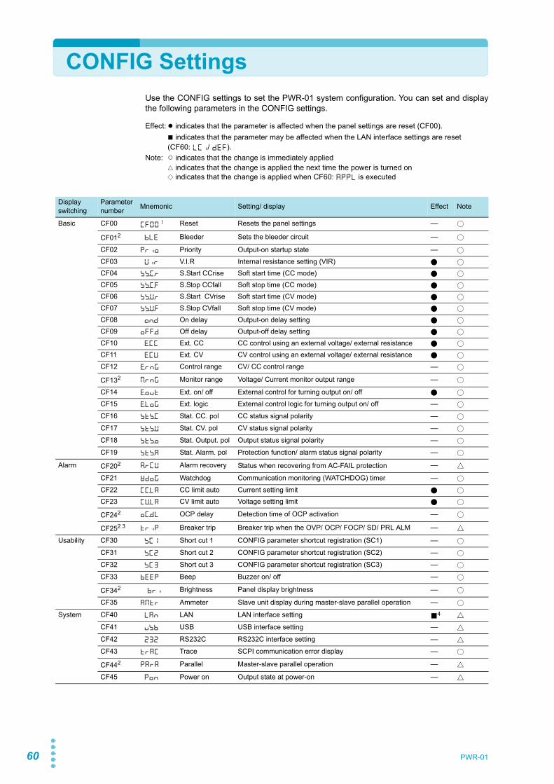
60 PWR-01
CONFIG SettingsUse the CONFIG settings to set the PWR-01 system configuration. You can set and displaythe following parameters in the CONFIG settings.
Effect: ● indicates that the parameter is affected when the panel settings are reset (CF00).■ indicates that the parameter may be affected when the LAN interface settings are reset (CF60: LCI/ DEF).
Note: ○ indicates that the change is immediately applied△ indicates that the change is applied the next time the power is turned on◇ indicates that the change is applied when CF60: APPL is executed
Display switching
Parameter number Mnemonic Setting/ display Effect Note
Basic CF00 CF001 Reset Resets the panel settings — ○
CF012 BLE Bleeder Sets the bleeder circuit — ○CF02 PRIO Priority Output-on startup state — ○CF03 VIR V.I.R Internal resistance setting (VIR) ● ○CF04 SS.C.R S.Start CCrise Soft start time (CC mode) ● ○CF05 SS.C.F S.Stop CCfall Soft stop time (CC mode) ● ○CF06 SS.V.R S.Start CVrise Soft start time (CV mode) ● ○CF07 SS.V.F S.Stop CVfall Soft stop time (CV mode) ● ○CF08 ON.D On delay Output-on delay setting ● ○CF09 OFF.D Off delay Output-off delay setting ● ○CF10 E.CC Ext. CC CC control using an external voltage/ external resistance ● ○CF11 E.CV Ext. CV CV control using an external voltage/ external resistance ● ○CF12 E.RNG Control range CV/ CC control range — ○CF132 M.RNG Monitor range Voltage/ Current monitor output range — ○CF14 E.OUT Ext. on/ off External control for turning output on/ off ● ○CF15 E.LOG Ext. logic External control logic for turning output on/ off — ○CF16 STS.C Stat. CC. pol CC status signal polarity — ○CF17 STS.V Stat. CV. pol CV status signal polarity — ○CF18 STS.O Stat. Output. pol Output status signal polarity — ○CF19 STS.A Stat. Alarm. pol Protection function/ alarm status signal polarity — ○
Alarm CF202 A.RCV Alarm recovery Status when recovering from AC-FAIL protection — △CF21 WDOG Watchdog Communication monitoring (WATCHDOG) timer — ○CF22 CC.LA CC limit auto Current setting limit ● ○CF23 CV.LA CV limit auto Voltage setting limit ● ○CF242 OC.DL OCP delay Detection time of OCP activation — ○
CF252 3 TRIP Breaker trip Breaker trip when the OVP/ OCP/ FOCP/ SD/ PRL ALM — △Usability CF30 SC1 Short cut 1 CONFIG parameter shortcut registration (SC1) — ○
CF31 SC2 Short cut 2 CONFIG parameter shortcut registration (SC2) — ○CF32 SC3 Short cut 3 CONFIG parameter shortcut registration (SC3) — ○CF33 BEEP Beep Buzzer on/ off — ○CF342 BRI Brightness Panel display brightness — ○CF35 AMTR Ammeter Slave unit display during master-slave parallel operation — ○
System CF40 LAN LAN LAN interface setting ■4 △CF41 USB USB USB interface setting — △CF42 232 RS232C RS232C interface setting — △CF43 TRAC Trace SCPI communication error display — ○CF442 PARA Parallel Master-slave parallel operation — △CF45 PON Power on Output state at power-on — △
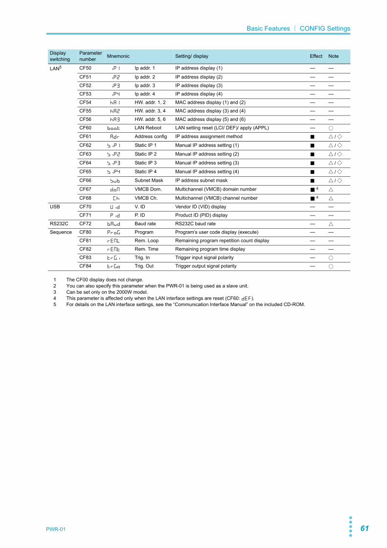
PWR-01 61
Basic Features| CONFIG Settings
LAN5 CF50 IP1 Ip addr. 1 IP address display (1) — —
CF51 IP2 Ip addr. 2 IP address display (2) — —CF52 IP3 Ip addr. 3 IP address display (3) — —CF53 IP4 Ip addr. 4 IP address display (4) — —CF54 HA1 HW. addr. 1, 2 MAC address display (1) and (2) — —CF55 HA2 HW. addr. 3, 4 MAC address display (3) and (4) — —CF56 HA3 HW. addr. 5, 6 MAC address display (5) and (6) — —CF60 BOOT LAN Reboot LAN setting reset (LCI/ DEF)/ apply (APPL) — ○CF61 ADR Address config IP address assignment method ■ △ / ◇CF62 S.IP1 Static IP 1 Manual IP address setting (1) ■ △ / ◇CF63 S.IP2 Static IP 2 Manual IP address setting (2) ■ △ / ◇CF64 S.IP3 Static IP 3 Manual IP address setting (3) ■ △ / ◇CF65 S.IP4 Static IP 4 Manual IP address setting (4) ■ △ / ◇CF66 SUB Subnet Mask IP address subnet mask ■ △ / ◇CF67 DOM VMCB Dom. Multichannel (VMCB) domain number ■ 4 △CF68 CH VMCB Ch. Multichannel (VMCB) channel number ■ 4 △
USB CF70 VID V. ID Vendor ID (VID) display — —CF71 PID P. ID Product ID (PID) display — —
RS232C CF72 BAUD Baud rate RS232C baud rate — △Sequence CF80 PROG Program Program’s user code display (execute) — —
CF81 REM.L Rem. Loop Remaining program repetition count display — —CF82 REM.T Rem. Time Remaining program time display — —CF83 TRG.I Trig. In Trigger input signal polarity — ○CF84 TRG.O Trig. Out Trigger output signal polarity — ○
1 The CF00 display does not change.2 You can also specify this parameter when the PWR-01 is being used as a slave unit.3 Can be set only on the 2000W model.4 This parameter is affected only when the LAN interface settings are reset (CF60: DEF).5 For details on the LAN interface settings, see the “Communication Interface Manual” on the included CD-ROM.
Display switching
Parameter number Mnemonic Setting/ display Effect Note

62 PWR-01
Basic Features| CONFIG Settings
CONFIG key
CONFIG key
CONFIG key
CONFIG key
CONFIG key
CONFIG key
CONFIG key
CONFIG key
CONFIG key
CONFIG key
※
Measured value display
Mnemonic display
Basic settings
Basic settings (external)
Alarm settings
...
CF00CF01
CF09
CF10CF11
CF19
CF20CF21
CF25
Usability settings
......
CF30CF31
CF35
System settings CF40CF41
CF45
......
VOLTAGE knob
CF00
BLE
OFF.D
... VOLTAGE knob+
LOCAL key
E.CC
E.CV
STS.A
... VOLTAGE knob+
LOCAL key
A.RCU
WDOG
OC.DL
... VOLTAGE knob+
LOCAL key
SC1
SC2
AMTR
... VOLTAGE knob+
LOCAL key
LAN
USB
PON
... VOLTAGE knob+
LOCAL key
IP1
IP2
HA3
... VOLTAGE knob+
LOCAL key
BOOT
ADR
CH
... VOLTAGE knob+
LOCAL key
VID
PID
BAUD
... VOLTAGE knob+
LOCAL key
PROG
REM.L
TRG.O
... VOLTAGE knob+
LOCAL key
VOLTAGE knob
VOLTAGE knob
VOLTAGE knob
VOLTAGE knob
LAN settings (display) ...
CF50CF51
CF56
LAN settings (setting) ...
...
CF60CF61
CF68
USB/RS232C settings
CF70CF71CF72
VOLTAGE knob
VOLTAGE knob
VOLTAGE knob
Sequence settings CF80CF81
CF84
VOLTAGE knob
※CF25 is available only on the 2000W model.
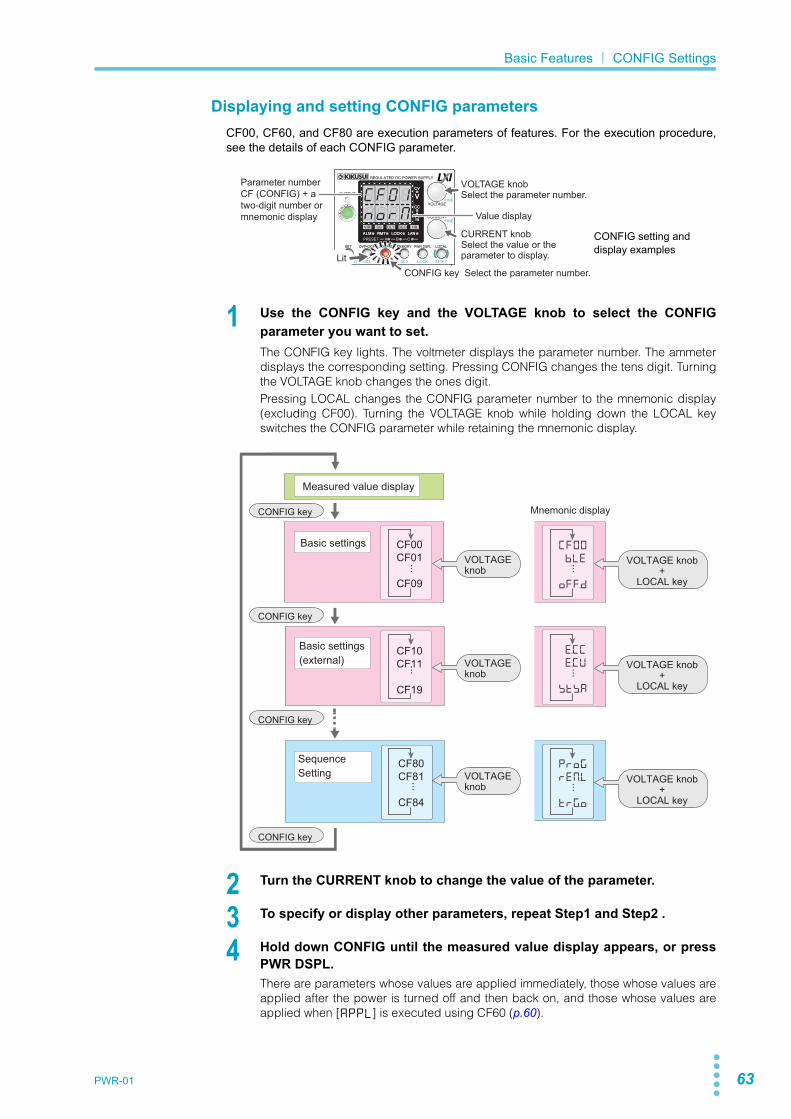
PWR-01 63
Basic Features| CONFIG Settings
Displaying and setting CONFIG parametersCF00, CF60, and CF80 are execution parameters of features. For the execution procedure,see the details of each CONFIG parameter.
1 Use the CONFIG key and the VOLTAGE knob to select the CONFIGparameter you want to set.The CONFIG key lights. The voltmeter displays the parameter number. The ammeterdisplays the corresponding setting. Pressing CONFIG changes the tens digit. Turningthe VOLTAGE knob changes the ones digit.Pressing LOCAL changes the CONFIG parameter number to the mnemonic display(excluding CF00). Turning the VOLTAGE knob while holding down the LOCAL keyswitches the CONFIG parameter while retaining the mnemonic display.
2 Turn the CURRENT knob to change the value of the parameter.
3 To specify or display other parameters, repeat Step1 and Step2 .
4 Hold down CONFIG until the measured value display appears, or pressPWR DSPL.There are parameters whose values are applied immediately, those whose values areapplied after the power is turned off and then back on, and those whose values areapplied when [APPL] is executed using CF60 (p.60).
CONFIG setting and display examples
CV
CC
/W
V
A
ALM RMT LOCK LAN
B CAPRESET
DLY SEQ HBSSVIR
CV
CC
/W
V
A
ALM RMT LOCK LAN
SC2 SC3 LOCKALM CLR SC1 SHIFT
FINE
FINE
REGULATED DC POWER SUPPLY
OUTPUT
VOLTAGE
CURRENT
CONFIG PWR DSPLMEMORY LOCALSET OVP•OCP
Lit
Value display
CONFIG key Select the parameter number.
Parameter numberCF (CONFIG) + a two-digit number ormnemonic display
VOLTAGE knobSelect the parameter number.
CURRENT knobSelect the value or the parameter to display.
CONFIG key
CONFIG key
CONFIG key
CONFIG key
Measured value display
Mnemonic display
Basic settings
Basic settings(external)
CF00CF01
CF09
CF10CF11
CF19
......
VOLTAGEknob
CF00
BLE
OFF.D
... VOLTAGE knob+
LOCAL key
E.CC
E.CV
STS.A
... VOLTAGE knob+
LOCAL key
PROG
REM.L
TRG.O
... VOLTAGE knob+
LOCAL key
VOLTAGEknob
...
SequenceSetting
CF80CF81
CF84
VOLTAGEknob
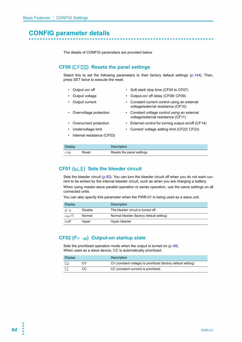
64 PWR-01
Basic Features| CONFIG Settings
CONFIG parameter details
The details of CONFIG parameters are provided below.
CF00 (CF00) Resets the panel settingsSelect this to set the following parameters to their factory default settings (p.144). Then,press SET twice to execute the reset.
CF01 (BLE) Sets the bleeder circuitSets the bleeder circuit (p.82). You can turn the bleeder circuit off when you do not want cur-rent to be sinked by the internal bleeder circuit, such as when you are charging a battery.When using master-slave parallel operation or series operation, use the same settings on allconnected units.You can also specify this parameter when the PWR-01 is being used as a slave unit.
CF02 (PRIO) Output-on startup stateSets the prioritized operation mode when the output is turned on (p.49).When used as a slave device, CC is automatically prioritized.
• Output on/ off • Soft start/ stop time (CF04 to CF07)• Output voltage • Output-on/ off delay (CF08/ CF09)• Output current • Constant current control using an external
voltage/external resistance (CF10)• Overvoltage protection • Constant voltage control using an external
voltage/external resistance (CF11)• Overcurrent protection • External control for turning output on/off (CF14)• Undervoltage limit • Current/ voltage setting limit (CF22/ CF23)• Internal resistance (CF03)
Display Description
RST Reset Resets the panel settings
Display Description
DIS Disable The bleeder circuit is turned off.
NORM Normal Normal bleeder (factory default setting)
HYP Hyper Hyper bleeder
Display Description
CV CV CV (constant voltage) is prioritized (factory default setting)
CC CC CC (constant current) is prioritized.

PWR-01 65
Basic Features| CONFIG Settings
CF03 (VIR) Internal resistance setting (VIR)Sets the internal resistance (Rint) (p.84). The internal resistance setting range (p.84) variesdepending on the model.
CF04 (SS.C.R) Soft start time (CC mode)Sets the rise time of the output current (p.43).You can set the output current to rise gradually.
CF05 (SS.C.F) Soft stop time (CC mode)Sets the fall time of the output current (p.43).You can set the output current to fall gradually.
CF06 (SS.V.R) Soft start time (CV mode)Sets the rise time of the output voltage (p.43).You can set the output voltage to rise gradually.
CF07 (SS.V.F) Soft stop time (CV mode)Sets the fall time of the output voltage (p.43).You can set the output voltage to fall gradually.
CF08 (ON.D) Output-on delay settingYou can set the delay from when the OUTPUT key is pressed to when the output actuallyturns on (p.42).
Display Description
OFF OFF Variable internal resistance function is not used (factory default setting).
Rint (min) to Rint (max) Rint (min) Ω to Rint (max) Ω
Display Description
0.0 0.0 Disable soft start (factory default setting)
0.5 to 10.0 0.5 to 10.0 Soft start time, 0.5 s to 10.0 s
Display Description
0.0 0.0 Disable soft stop (factory default setting)
0.5 to 10.0 0.5 to 10.0 Soft stop time, 0.5 s to 10.0 s
Display Description
0.0 0.0 Disable soft start (factory default setting)
0.5 to 10.0 0.5 to 10.0 Soft start time, 0.5 s to 10.0 s
Display Description
0.0 0.0 Disable soft stop (factory default setting)
0.5 to 10.0 0.5 to 10.0 Soft stop time, 0.5 s to 10.0 s
Display Description
0.0 0.0 No delay (factory default setting)
0.5 to 99.9 0.5 to 99.9 Output-on delay time, 0.5 s to 99.9 s

66 PWR-01
Basic Features| CONFIG Settings
CF09 (OFF.D) Output-off delay settingYou can set the delay from when the OUTPUT key is pressed to when the output actuallyturns off (p.42).
CF10 (E.CC) CC control using an external voltage/ external resistanceEnables or disables constant current control using an external voltage or external resistance(p.98).
CF11 (E.CV) CV control using an external voltage/ external resistanceEnables or disables constant voltage control using an external voltage or external resistance(p.96).
CF12 (E.RNG) CV/ CC control rangeSets the range for performing constant current or constant voltage control using an externalvoltage or external resistance (p.96, p.98).Reference voltage for external control (J1-3 REFOUT) is also set to 5.25 V (CF12: LO) or10.5 V (CF12: HI) according to the range setting.
CF13 (M.RNG) Voltage/ Current monitor output rangeSets the voltage range when monitoring voltage or current (p.104). You can also set thisparameter when the PWR-01 is being used as a slave unit.
Display Description
0.0 0.0 No delay (factory default setting)
0.5 to 99.9 0.5 to 99.9 Output-off delay time, 0.5 s to 99.9 s
Display Description
OFF OFF Disabled (factory default setting)
ON ON Enabled
Display Description
OFF OFF Disabled (factory default setting)
ON ON Enabled
Display Description
LO LOW 0 V to 5 V (factory default setting)
HI HIGH 0 V to 10 V
Display Description
LO LOW 0 V to 5 V (factory default setting)
HI HIGH 0 V to 10 V

PWR-01 67
Basic Features| CONFIG Settings
CF14 (E.OUT) External control for turning output on/ offEnables or disables output on/off control using an external contact (p.100) and enables ordisables the output-on/ off delay function and soft start and soft stop functions. (p.42, p.43)..
CF15 (E.LOG) External control logic for turning output on/ offSets the logic that is used for output on/ off control using an external contact (p.100).
CF16 (STS.C) CC status signal polaritySets the polarity of the status signal for monitoring the constant-current mode (p.104).
CF17 (STS.V) CV status signal polaritySets the polarity of the status signal for monitoring the constant-voltage mode (p.104).
CF18 (STS.O) Output status signal polaritySets the polarity of the status signal for monitoring the output-on state (p.104).
CF19 (STS.A) Protection function/ alarm status signal polaritySets the polarity of the status signal for monitoring the protection function or alarm (p.104).
Display Description
OFF OFF Disabled (factory default setting)
ON ON Enabled
ENH Enhanced On EnabledUse the output-on/ off delay and soft start and soft stop functions
Display Description
LO LOW The output is turned on with a low signal (0 V to 0.5 V) or short cir-cuit (factory default setting).
HI HIGH The output is turned on with a high signal (4.5 V to 5 V) or open cir-cuit.
Display Description
NEG Negative Negative (factory default setting)
POS Positive Positive
Display Description
NEG Negative Negative (factory default setting)
POS Positive Positive
Display Description
NEG Negative Negative (factory default setting)
POS Positive Positive
Display Description
NEG Negative Negative (factory default setting)
POS Positive Positive

68 PWR-01
Basic Features| CONFIG Settings
CF20 (A.RCV) Status when recovering from AC-FAIL protectionSets the output status for when the AC power line returns to normal while a low AC input pro-tection (AC-FAIL) is activated (p.56).This parameter is applied when you turn the POWER switch off and on.You can also set this parameter when the PWR-01 is being used as a slave unit.
CF21 (WDOG) Communication monitoring (WATCHDOG) timerSets the interval for monitoring SCPI command communication (p.56).The communication monitoring operates regardless of whether the product is in remote orlocal (panel control) mode.If you are not using remote control (commands), set this to “OFF”.
CF22 (CC.LA) Current setting limitSets whether to limit the output current setting at the OCP trip point (about 95 % of the OCPtrip point) (p.53).
CF23 (CV.LA) Voltage setting limitSets whether to limit the output voltage setting at the OVP trip point (about 95 % of the OVPtrip point) or at the UVL trip point (p.52).
CF24 (OC.DL) Detection time of OCP activationSets the time from when an overcurrent is detected to when the OCP is activated in steps of100 ms .You can also set this parameter when the PWR-01 is being used as a slave unit.
Display Description
SAFE Safe The alarm status is retained even after the problem that caused the alarm is fixed. (factory default setting)
AUTO Auto The alarm status is cleared after the problem that caused the alarm is fixed (returns to the status before the alarm occurrence).
Display Description
OFF OFF Communication monitor timer is set to off (factory default setting).
1 to 3000 1 to 3000 1 s, 3 s, 10 s, 30 s, 100 s, 300 s, 1000 s, 3000 s
Display Description
OFF OFF The setting is not limited.
ON ON The setting is limited (factory default setting).
Display Description
OFF OFF The setting is not limited.
ON ON The setting is limited (factory default setting).
Display Description
0.0 0.0 0.0 s (factory default setting)
0.1 to 2.0 0.1 to 2.0 0.1 s to 2.0 s

PWR-01 69
Basic Features| CONFIG Settings
CF25(TRIP) Breaker trip when the OVP/ OCP/ FOCP/ SD/ PRL ALM (Only on the 2000W model)
Sets whether to trip the breaker (turn the POWER switch off) when the overvoltage protection(OVP), overcurrent protection (OCP), Front-panel output terminal overcurrent protection(FOCP), Shutdown (SD) or Master-slave parallel operation protection (PRL ALM) is activated(p.41). This parameter is applied when you turn the POWER switch off and on. The setting is possi-ble even when the product is used as a slave unit.
CF30 (SC1) CONFIG parameter shortcut registration (SC1)Registers a CONFIG setting parameter to the front panel’s SC1 key (p.79).
CF31 (SC2) CONFIG parameter shortcut registration (SC2)Registers a CONFIG setting parameter to the front panel’s SC2 key (p.79).
CF32 (SC3) CONFIG parameter shortcut registration (SC3)Registers a CONFIG setting parameter to the front panel’s SC3 key (p.79).
CF33 (BEEP) Buzzer on/ offTurns the buzzer on and off.The buzzer sounds when settings are reset to factory defaults, when a communication com-mand error occurs, or when a preset memory or sequence program cannot be recalled.
Display Description
OFF OFF Not trip (turn the output off)
ON ON Trip (turn the POWER switch off) (factory default)
Display Description
00 00 CONFIG parameter not registered (factory default setting)
01 to 99 01 to 99 CF01 to CF99
Display Description
00 00 CONFIG parameter not registered (factory default setting)
01 to 99 01 to 99 CF01 to CF99
Display Description
00 00 CONFIG parameter not registered (factory default setting)
01 to 99 01 to 99 CF01 to CF99
Display Description
OFF OFF Buzzer off
ON ON Buzzer on (factory default setting).

70 PWR-01
Basic Features| CONFIG Settings
CF34 (BRI) Panel display brightnessSets the panel display brightness. The larger the number, the brighter the display.Even if you specify the same number, the brightness may be different between individualproducts.The brightness is not proportional to the setting.You can also set this parameter when the PWR-01 is being used as a slave unit.
CF35 (AMTR) Slave unit display during master-slave parallel oper-ation
Sets whether the current or power on slave units is displayed during master-slave paralleloperation. If the slave unit display is disabled, the ammeter shows "----.”
CF40 (LAN) LAN interface settingEnables or disables the LAN interface.By setting this parameter to “OFF,” you can disable the LAN interface function even when aLAN cable is connected.This parameter is applied when you turn the POWER switch off and on.
CF41 (USB) USB interface settingEnables or disables the USB interface.By setting this parameter to “OFF,” you can disable the USB interface function even when aUSB cable is connected.This parameter is applied when you turn the POWER switch off and on.
CF42 (232) RS232C interface settingEnables or disables the RS232C interface.By setting this parameter to “OFF,” you can disable the RS232C interface function even whena RS232C cable is connected.This parameter is applied when you turn the POWER switch off and on.
Display Description
1 to 7 1 to 7 Screen brightness adjustment (factory default setting: 7)
Display Description
OFF OFF Slave unit display disabled (factory default setting)
ON ON Slave unit enabled
Display Description
OFF OFF LAN disabled
ON ON LAN enabled (factory default setting).
Display Description
OFF OFF USB disabled
ON ON USB enabled (factory default setting).
Display Description
OFF OFF RS232C disabled
ON ON RS232C enabled (factory default setting).
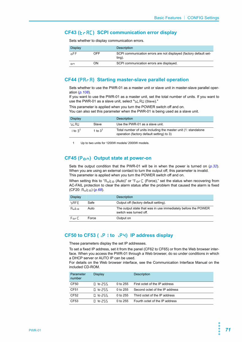
PWR-01 71
Basic Features| CONFIG Settings
CF43 (TRAC) SCPI communication error displaySets whether to display communication errors.
CF44 (PARA) Starting master-slave parallel operationSets whether to use the PWR-01 as a master unit or slave unit in master-slave parallel oper-ation (p.108).If you want to use the PWR-01 as a master unit, set the total number of units. If you want touse the PWR-01 as a slave unit, select "SLAV (Slave)."This parameter is applied when you turn the POWER switch off and on.You can also set this parameter when the PWR-01 is being used as a slave unit.
CF45 (PON) Output state at power-onSets the output condition that the PWR-01 will be in when the power is turned on (p.32).When you are using an external contact to turn the output off, this parameter is invalid.This parameter is applied when you turn the POWER switch off and on.When setting this to “AUTO (Auto)” or “FORC (Force),” set the status when recovering fromAC-FAIL protection to clear the alarm status after the problem that caused the alarm is fixed(CF20: AUTO) (p.68).
CF50 to CF53 (IP1 to IP4) IP address displayThese parameters display the set IP addresses.To set a fixed IP address, set it from the panel (CF62 to CF65) or from the Web browser inter-face. When you access the PWR-01 through a Web browser, do so under conditions in whicha DHCP server or AUTO IP can be used.For details on the Web browser interface, see the Communication Interface Manual on theincluded CD-ROM.
Display Description
OFF OFF SCPI communication errors are not displayed (factory default set-ting).
ON ON SCPI communication errors are displayed.
Display Description
SLAV Slave Use the PWR-01 as a slave unit.
1 to 31
1 Up to two units for 1200W models/ 2000W models.
1 to 31 Total number of units including the master unit (1: standalone operation (factory default setting) to 3)
Display Description
SAFE Safe Output off (factory default setting).
AUTO Auto The output state that was in use immediately before the POWER switch was turned off.
FORC Force Output on
Parameter number
Display Description
CF50 0. to 255. 0 to 255 First octet of the IP address
CF51 0. to 255. 0 to 255 Second octet of the IP address
CF52 0. to 255. 0 to 255 Third octet of the IP address
CF53 0 to 255 0 to 255 Fourth octet of the IP address
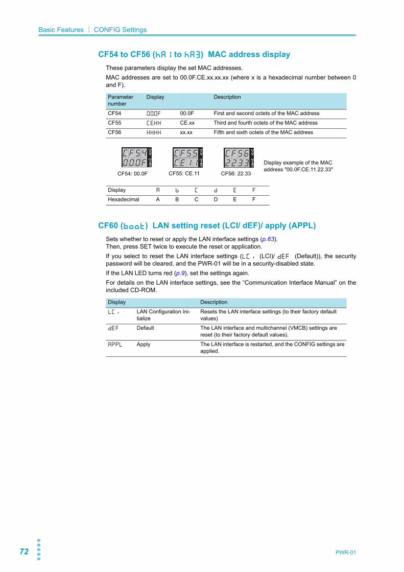
72 PWR-01
Basic Features| CONFIG Settings
CF54 to CF56 (HA1 to HA3) MAC address displayThese parameters display the set MAC addresses.MAC addresses are set to 00.0F.CE.xx.xx.xx (where x is a hexadecimal number between 0and F).
CF60 (BOOT) LAN setting reset (LCI/ dEF)/ apply (APPL)Sets whether to reset or apply the LAN interface settings (p.63).Then, press SET twice to execute the reset or application.If you select to reset the LAN interface settings (LCI (LCI)/ DEF (Default)), the securitypassword will be cleared, and the PWR-01 will be in a security-disabled state.If the LAN LED turns red (p.9), set the settings again.For details on the LAN interface settings, see the “Communication Interface Manual” on theincluded CD-ROM.
Parameter number
Display Description
CF54 00.0F 00.0F First and second octets of the MAC address
CF55 CE.XX CE.xx Third and fourth octets of the MAC address
CF56 XX.XX xx.xx Fifth and sixth octets of the MAC address
Display A B C D E F
Hexadecimal A B C D E F
CV
CC
/W
V
A
CV
CC
/W
V
A
CV
CC
/W
V
A
CV
CC
/W
V
A
CV
CC
/W
V
A
CV
CC
/W
V
A Display example of the MAC address "00.0F.CE.11.22.33"
CF54: 00.0F CF56: 22.33CF55: CE.11
Display Description
LCI LAN Configuration Ini-tialize
Resets the LAN interface settings (to their factory default values)
DEF Default The LAN interface and multichannel (VMCB) settings are reset (to their factory default values).
APPL Apply The LAN interface is restarted, and the CONFIG settings areapplied.

PWR-01 73
Basic Features| CONFIG Settings
CF61 (ADR) IP address assignment methodSets the IP address assignment method.Set whether to use (on: 1) or not use (off: 0) the following: DHCP server, AUTO IP function(automatic assignment), and MANUAL IP function (manual assignment).If DHCP and AUTO IP are both set to on and an IP address is not assigned through a DHCPserver, AUTO IP is used.To use MANUAL IP, set DHCP and AUTO IP to off. The IP address that is assigned by theAUTO IP function is 169.254.x.x (where x is a number between 1 and 254).This parameter is applied when you turn the POWER switch off and on or when you executeAPPL (Apply) with CF60.
CF62 to CF65 (S.IP1 to S.IP4) Manual IP address setting (MANUAL IP)If you are not using the DHCP server or the AUTO IP function, set the IP address manually.To do so, use CF61 to set MANUAL IP to on.This parameter is applied when you turn the POWER switch off and on or when you executeAPPL (Apply) with CF60.
CF66 (SUB) IP address subnet maskIf you want to set the IP address manually (MANUAL IP), set the subnet mask prefix. To doso, use CF61 to set MANUAL IP to on.This parameter is applied when you turn the POWER switch off and on or when you executeAPPL (Apply) with CF60.
Examples:Display example when “16” is selected 255.255.0.0Display example when “24” is selected 255.255.255.0Display example when “31” is selected 255.255.255.255
Display Description
001 001 DHCP: off, AUTO IP: off, MANUAL IP: on
010 010 DHCP: off, AUTO IP: on, MANUAL IP: off
011 011 DHCP: off, AUTO IP: on, MANUAL IP: on
100 100 DHCP: on, AUTO IP: off, MANUAL IP: off
101 101 DHCP: on, AUTO IP: off, MANUAL IP: on
110 110 DHCP: on, AUTO IP: on, MANUAL IP: off (factory default setting)
111 111 DHCP: on, AUTO IP: on, MANUAL IP: on
Parameter number
Display Description
CF62 0. to 255 0 to 255 First octet of the IP address
CF63 0. to 255 0 to 255 Second octet of the IP address
CF64 0. to 255 0 to 255 Third octet of the IP address
CF65 0. to 255 0 to 255 Fourth octet of the IP address
Display Description
16 to 31 16 to 31 Sets the subnet mask prefix

74 PWR-01
Basic Features| CONFIG Settings
CF67 (DOM) Multichannel (VMCB) domain numberSet the multichannel domain number. PWR-01s that have the same domain number performmultichannel operations. If you do not want to use the multichannel function, set this to “0”(this is the factory default setting).This parameter is applied when you turn the POWER switch off and on.For details on the multichannel function, see the Communication Interface Manual on theincluded CD-ROM.
CF68 (CH) Multichannel (VMCB) channel numberSet the multichannel channel number. Specify a unique number on the network. If you do notwant to use the multichannel function, set this to “0” (this is the factory default setting).This parameter is applied when you turn the POWER switch off and on.For details on the multichannel function, see the Communication Interface Manual on theincluded CD-ROM.
CF70 (VID) Vendor ID (VID) displayThis displays the USB vendor ID.
CF71 (PID) Product ID displayThis displays the USB product ID.
Display Description
0 0 The multichannel function is not used (factory default setting).
1 to 254 1 to 254 The domain number when the multichannel function is used.
Display Description
0 0 Master unit on the multichannel network (factory default setting).
1 to 30 1 to 30 Channel number of the slave unit on the multichannel network.
Display Vendor ID.
0B3E 0b3E 0x0B3E
400W model 800W modelDisplay Product ID: Display Product ID:
1049 1049 0x1049 104A 104A 0x104A
1200W model 2000W modelDisplay Product ID: Display Product ID:
104B 104B 0x104B 1055 1055 0x1055
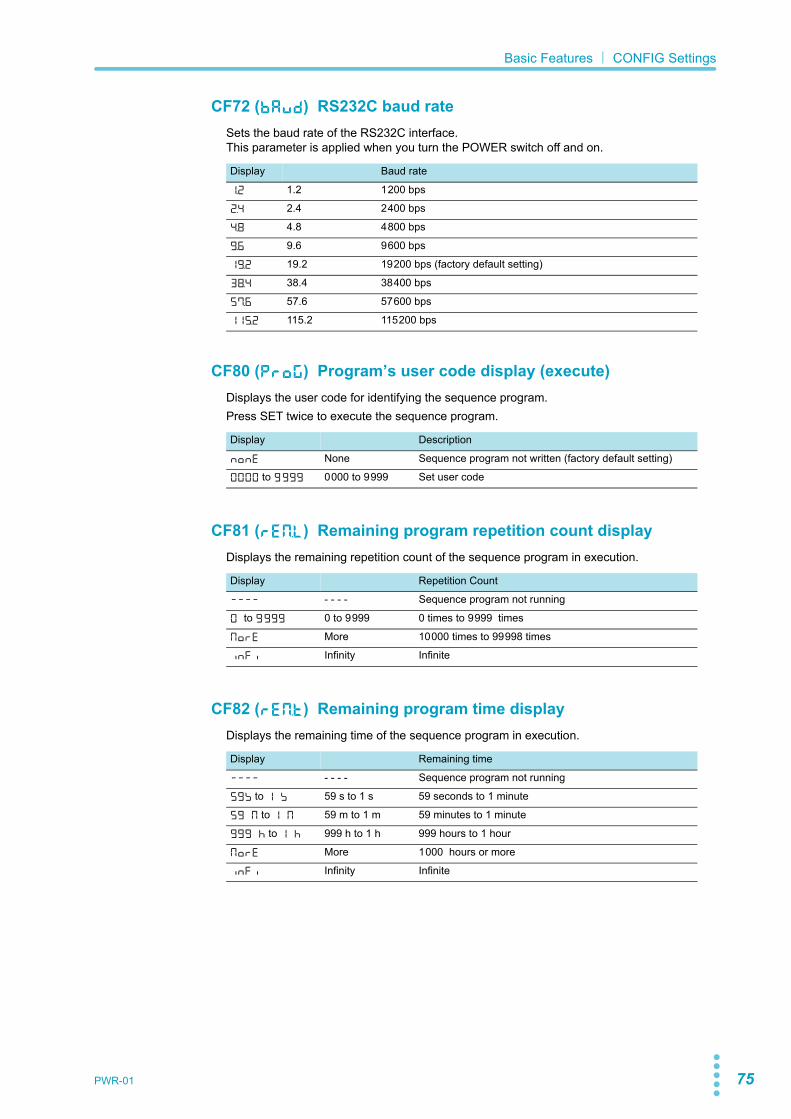
PWR-01 75
Basic Features| CONFIG Settings
CF72 (BAUD) RS232C baud rateSets the baud rate of the RS232C interface.This parameter is applied when you turn the POWER switch off and on.
CF80 (PROG) Program’s user code display (execute)Displays the user code for identifying the sequence program.Press SET twice to execute the sequence program.
CF81 (REM.L) Remaining program repetition count displayDisplays the remaining repetition count of the sequence program in execution.
CF82 (REM.T) Remaining program time displayDisplays the remaining time of the sequence program in execution.
Display Baud rate
1.2 1.2 1200 bps
2.4 2.4 2400 bps
4.8 4.8 4800 bps
9.6 9.6 9600 bps
19.2 19.2 19200 bps (factory default setting)
38.4 38.4 38400 bps
57.6 57.6 57600 bps
115.2 115.2 115200 bps
Display Description
NONE None Sequence program not written (factory default setting)
0000 to 9999 0000 to 9999 Set user code
Display Repetition Count
---- - - - - Sequence program not running
0 to 9999 0 to 9999 0 times to 9999 times
MORE More 10000 times to 99998 times
INFI Infinity Infinite
Display Remaining time
---- - - - - Sequence program not running
59S to 1 S 59 s to 1 s 59 seconds to 1 minute
59 M to 1 M 59 m to 1 m 59 minutes to 1 minute
999 H to 1 H 999 h to 1 h 999 hours to 1 hour
MORE More 1000 hours or more
INFI Infinity Infinite

76 PWR-01
Basic Features| CONFIG Settings
CF83 (TRG.I) Trigger input signal polaritySets the polarity of the trigger input signal.Trigger signals are used to resume a sequence step and to perform synchronized operation.
CF84 (TRG.O) Trigger output signal polaritySets the polarity of the trigger output signal.Trigger signals are output when a program step is resumed or when the output is turned on(must be set with a command).
Display Description
PTR Positive Trigger Positive trigger (factory default setting)
NTR Negative Trigger Negative trigger
Display Description
PTR Positive Trigger Positive trigger (factory default setting)
NTR Negative Trigger Negative trigger
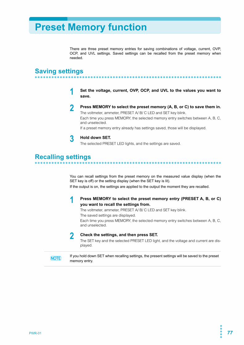
PWR-01 77
Preset Memory function
There are three preset memory entries for saving combinations of voltage, current, OVP,OCP, and UVL settings. Saved settings can be recalled from the preset memory whenneeded.
Saving settings
1 Set the voltage, current, OVP, OCP, and UVL to the values you want tosave.
2 Press MEMORY to select the preset memory (A, B, or C) to save them in.The voltmeter, ammeter, PRESET A/ B/ C LED and SET key blink.Each time you press MEMORY, the selected memory entry switches between A, B, C,and unselected.If a preset memory entry already has settings saved, those will be displayed.
3 Hold down SET.The selected PRESET LED lights, and the settings are saved.
Recalling settings
You can recall settings from the preset memory on the measured value display (when theSET key is off) or the setting display (when the SET key is lit).If the output is on, the settings are applied to the output the moment they are recalled.
1 Press MEMORY to select the preset memory entry (PRESET A, B, or C)you want to recall the settings from.The voltmeter, ammeter, PRESET A/ B/ C LED and SET key blink.The saved settings are displayed.Each time you press MEMORY, the selected memory entry switches between A, B, C,and unselected.
2 Check the settings, and then press SET.The SET key and the selected PRESET LED light, and the voltage and current are dis-played.
If you hold down SET when recalling settings, the present settings will be saved to the preset memory entry.
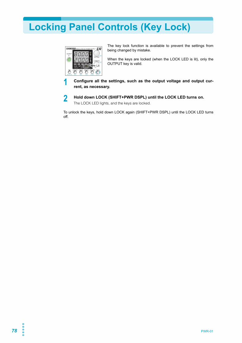
78 PWR-01
Locking Panel Controls (Key Lock)The key lock function is available to prevent the settings frombeing changed by mistake.
When the keys are locked (when the LOCK LED is lit), only theOUTPUT key is valid.
1 Configure all the settings, such as the output voltage and output cur-rent, as necessary.
2 Hold down LOCK (SHIFT+PWR DSPL) until the LOCK LED turns on.The LOCK LED lights, and the keys are locked.
To unlock the keys, hold down LOCK again (SHIFT+PWR DSPL) until the LOCK LED turnsoff.
CV
CC
/W
V
A
ALM RMT LOCK LAN
B CAPRESET
DLY SEQ HBSSVIR
CV
CC
/W
V
A
ALM RMT LOCK LAN
SC2 SC3 LOCKALM CLR SC1 SHIFT
FINE
FINE
REGULATED DC POWER SUPPLY
OUTPUT
VOLTAGE
CURRENT
CONFIG PWR DSPLMEMORY LOCALSET OVP•OCP
Lit

PWR-01 79
CONFIG Shortcut function
There is a CONFIG shortcut function that allows up to three CONFIG parameters of yourchoice (SC1, SC2, and SC3) to be registered. Registered CONFIG parameters can berecalled with the SC key without having to enter the CONFIG menu.
Registering CONFIG shortcuts
1 Press CONFIG four times (CF30).
2 Turn the VOLTAGE knob to select the CONFIG parameter number (CF30, CF31, or CF32) in which to register a shortcut.CF30, CF31, and CF32 are assigned to SC1, SC2, and SC3, respectively.
3 Turn the CURRENT knob to set the CONFIG parameter number you wantto register.
4 Hold down CONFIG until the measured value display appears, or pressPWR DSPL.The setting is are applied immediately.
Using CONFIG shortcuts
1 Press SHIFT+SC1, SC2, or SC3 in which the CONFIG parameter youwant to recall is registered.The registered CONFIG parameter is displayed.
2 Hold down CONFIG until the measured value display appears, or pressPWR DSPL.
CV
CC
/W
V
A
ALM RMT LOCK LAN
B CAPRESET
DLY SEQ HBSSVIR
CV
CC
/W
V
A
ALM RMT LOCK LAN
SC2 SC3 LOCKALM CLR SC1 SHIFT
FINE
FINE
REGULATED DC POWER SUPPLY
OUTPUT
VOLTAGE
CURRENT
CONFIG PWR DSPLMEMORY LOCALSET OVP•OCP
Lit
CONFIG parameter number in which to register a shortcut
CONFIG parameter number you want to register
Example in which “CF21” is being registered to the SC1 key
Example in which “CF21” is being called with the SC1 key
CV
CC
/W
V
A
ALM RMT LOCK LAN
B CAPRESET
DLY SEQ HBSSVIR
CV
CC
/W
V
A
ALM RMT LOCK LAN
SC2 SC3 LOCKALM CLR SC1 SHIFT
FINE
FINE
REGULATED DC POWER SUPPLY
OUTPUT
VOLTAGE
CURRENT
CONFIG PWR DSPLMEMORY LOCALSET OVP•OCP
Lit

80 PWR-01
Switching from Remote Mode to Local Mode
When the PWR-01 is being controlled remotely, the RMT LED inthe display area lights.
To switch the PWR-01 to local mode from the front panel, pressLOCAL.
CV
CC
/W
V
A
ALM RMT LOCK LAN
B CAPRESET
DLY SEQ HBSSVIR
CV
CC
/W
V
A
ALM RMT LOCK LAN
SC2 SC3 LOCKALM CLR SC1 SHIFT
FINE
FINE
REGULATED DC POWER SUPPLY
OUTPUT
VOLTAGE
CURRENT
CONFIG PWR DSPLMEMORY LOCALSET OVP•OCP
Lit

Advanced FeaturesThis chapter describes how to useadvanced operations such as the bleedercircuit function, variable internal resistancefunction, sequence function and synchro-nized operation.

82 PWR-01
Bleeder Circuit function
Turn the bleeder circuit off when you do not want the internal bleeder circuit to sink outputcurrent. When you connect a battery, you can prevent excessive electrical discharges byturning the bleeder circuit off.
Set the bleeder circuit to off, normal bleeder, or hyper bleeder using a CONFIG setting(CF01).When the POWER switch is turned on the next time, the PWR-01 starts with the settings thatwere in use the last time that the POWER switch was turned off.
When using master-slave parallel operation or series operation, use the same settings on allconnected units. You can also specify this parameter when the PWR-01 is being used as aslave unit.Depending on whether the bleeder circuit setting, the sink current when an external voltagesource is connected will vary.
Sink current (reference value) from an external voltage source accordingto the bleeder circuit setting
WARNING Risk of electric shock. Set the bleeder circuit to on (CF01: NORM/ HYP) before you touch the output terminals. If it is set to off (CF01: DIS), the voltage that was present when the output was on will remain at the output terminals even if you turn off the out-put or POWER switch.
Bleeder circuit Displayed setting
Description
Off1
1 Even if the output terminals are open and the output is turned off or the voltage setting is at 0 V, up toseveral hundred millivolts of voltage may appear across the output terminals.
DIS Bleeder circuit off
Normal bleeder NORM Bleeder circuit on
Hyper bleeder HYP Bleeder circuit on. HB lights on the display. The fan speed is fixed to the maximum speed.Provides strong sink performance (see the table below).The fall time at no load is reduced to about 70 % of that using the nor-mal bleeder (reduction in test cycle time (takt time) is possible).
Vout= Output terminal voltage
Model Bleeder circuitSink current
5 Vout 10 Vout 15 Vout 20 Vout 30 Vout 40 Vout
PWR401L Off 0.000 A 0.000 A 0.001 A 0.001 A 0.002 A 0.003 A
Normal bleeder 0.381 A 0.347 A 0.312 A 0.277 A 0.208 A 0.139 A
Hyper bleeder 0.583 A 0.546 A 0.512 A 0.477 A 0.409 A 0.339 A
PWR801L Off 0.000 A 0.000 A 0.000 A 0.001 A 0.001 A 0.001 A
Normal bleeder 0.730 A 0.660 A 0.590 A 0.525 A 0.386 A 0.248 A
Hyper bleeder 1.130 A 1.060 A 1.000 A 0.930 A 0.780 A 0.640 A
PWR1201L Off 0.000 A 0.001 A 0.001 A 0.001 A 0.001 A 0.002 A
Normal bleeder 1.120 A 1.010 A 0.900 A 0.792 A 0.577 A 0.362 A
Hyper bleeder 1.720 A 1.620 A 1.510 A 1.410 A 1.200 A 1.000 A
PWR2001L Off 0.001 A 0.001 A 0.001 A 0.001 A 0.002 A 0.002 A
Normal bleeder 1.850 A 1.680 A 1.510 A 1.330 A 0.983 A 0.632 A
Hyper bleeder 2.840 A 2.670 A 2.490 A 2.320 A 1.970 A 1.630 A

PWR-01 83
Advanced Features| Bleeder Circuit function
Vout= Output terminal voltage
Model Bleeder circuitSink current
5 Vout 10 Vout 20 Vout 40 Vout 60 Vout 80 Vout
PWR401ML Off 0.000 A 0.000 A 0.000 A 0.001 A 0.001 A 0.002 A
Normal bleeder 0.376 A 0.360 A 0.328 A 0.264 A 0.200 A 0.136 A
Hyper bleeder 0.564 A 0.547 A 0.515 A 0.450 A 0.384 A 0.319 A
PWR801ML Off 0.000 A 0.000 A 0.000 A 0.000 A 0.000 A 0.001 A
Normal bleeder 0.754 A 0.721 A 0.656 A 0.526 A 0.395 A 0.265 A
Hyper bleeder 1.128 A 1.096 A 1.029 A 0.901 A 0.769 A 0.640 A
PWR1201ML Off 0.000 A 0.001 A 0.001 A 0.001 A 0.001 A 0.002 A
Normal bleeder 1.141 A 1.092 A 0.994 A 0.797 A 0.601 A 0.404 A
Hyper bleeder 1.700 A 1.650 A 1.550 A 1.360 A 1.160 A 0.970 A
Vout= Output terminal voltage
Model Bleeder circuitSink current
10 Vout 20 Vout 50 Vout 100 Vout 200 Vout 240 Vout
PWR401MH Off 0.000 A 0.001 A 0.001 A 0.001 A 0.001 A 0.002 A
Normal bleeder 0.151 A 0.147 A 0.134 A 0.114 A 0.072 A 0.056 A
Hyper bleeder 0.223 A 0.221 A 0.208 A 0.187 A 0.145 A 0.128 A
PWR801MH Off 0.000 A 0.000 A 0.000 A 0.001 A 0.001 A 0.002 A
Normal bleeder 0.304 A 0.295 A 0.267 A 0.221 A 0.128 A 0.091 A
Hyper bleeder 0.441 A 0.432 A 0.407 A 0.364 A 0.279 A 0.250 A
PWR1201MH Off 0.000 A 0.000 A 0.000 A 0.001 A 0.001 A 0.002 A
Normal bleeder 0.442 A 0.429 A 0.392 A 0.331 A 0.208 A 0.159 A
Hyper bleeder 0.661 A 0.648 A 0.610 A 0.546 A 0.419 A 0.370 A
Vout= Output terminal voltage
Model Bleeder circuitSink current
20 Vout 50 Vout 100 Vout 200 Vout 500 Vout 650 Vout
PWR401H Off 0.000 A 0.001 A 0.001 A 0.002 A 0.004 A 0.005 A
Normal bleeder 0.067 A 0.065 A 0.063 A 0.057 A 0.041 A 0.033 A
Hyper bleeder 0.081 A 0.080 A 0.077 A 0.072 A 0.057 A 0.049 A
PWR801H Off 0.000 A 0.000 A 0.001 A 0.003 A 0.007 A 0.009 A
Normal bleeder 0.128 A 0.125 A 0.119 A 0.108 A 0.075 A 0.059 A
Hyper bleeder 0.160 A 0.157 A 0.152 A 0.142 A 0.111 A 0.094 A
PWR1201H Off 0.000 A 0.000 A 0.001 A 0.004 A 0.009 A 0.012 A
Normal bleeder 0.197 A 0.192 A 0184 A 0.167 A 0.118 A 0.094 A
Hyper bleeder 0.231 A 0.227 A 0.219 A 0.204 A 0.160 A 0.140 A
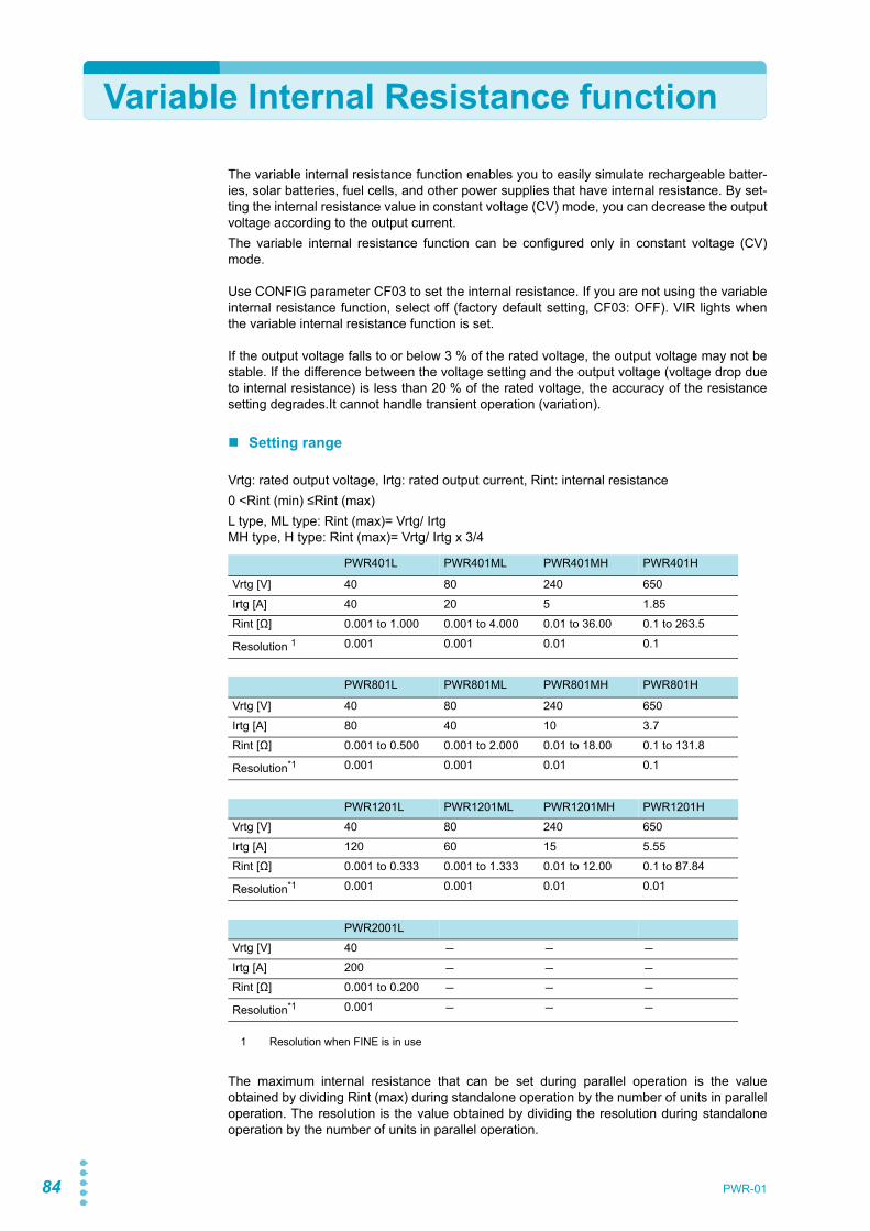
84 PWR-01
Variable Internal Resistance function
The variable internal resistance function enables you to easily simulate rechargeable batter-ies, solar batteries, fuel cells, and other power supplies that have internal resistance. By set-ting the internal resistance value in constant voltage (CV) mode, you can decrease the outputvoltage according to the output current.The variable internal resistance function can be configured only in constant voltage (CV)mode.
Use CONFIG parameter CF03 to set the internal resistance. If you are not using the variableinternal resistance function, select off (factory default setting, CF03: OFF). VIR lights whenthe variable internal resistance function is set.
If the output voltage falls to or below 3 % of the rated voltage, the output voltage may not bestable. If the difference between the voltage setting and the output voltage (voltage drop dueto internal resistance) is less than 20 % of the rated voltage, the accuracy of the resistancesetting degrades.It cannot handle transient operation (variation).
Setting range
Vrtg: rated output voltage, Irtg: rated output current, Rint: internal resistance0 <Rint (min) ≤Rint (max)L type, ML type: Rint (max)= Vrtg/ Irtg MH type, H type: Rint (max)= Vrtg/ Irtg x 3/4
The maximum internal resistance that can be set during parallel operation is the valueobtained by dividing Rint (max) during standalone operation by the number of units in paralleloperation. The resolution is the value obtained by dividing the resolution during standaloneoperation by the number of units in parallel operation.
PWR401L PWR401ML PWR401MH PWR401H
Vrtg [V] 40 80 240 650Irtg [A] 40 20 5 1.85Rint [Ω] 0.001 to 1.000 0.001 to 4.000 0.01 to 36.00 0.1 to 263.5
Resolution 1
1 Resolution when FINE is in use
0.001 0.001 0.01 0.1
PWR801L PWR801ML PWR801MH PWR801H
Vrtg [V] 40 80 240 650Irtg [A] 80 40 10 3.7Rint [Ω] 0.001 to 0.500 0.001 to 2.000 0.01 to 18.00 0.1 to 131.8
Resolution*1 0.001 0.001 0.01 0.1
PWR1201L PWR1201ML PWR1201MH PWR1201HVrtg [V] 40 80 240 650Irtg [A] 120 60 15 5.55Rint [Ω] 0.001 to 0.333 0.001 to 1.333 0.01 to 12.00 0.1 to 87.84
Resolution*1 0.001 0.001 0.01 0.01
PWR2001LVrtg [V] 40 - - -Irtg [A] 200 - - -Rint [Ω] 0.001 to 0.200 - - -Resolution*1 0.001 - - -

PWR-01 85
Sequence function
The sequence function enables you to automatically execute programs that you have set inadvance one operation at a time.You cannot configure sequence programs from the panel. Programs are created using com-mands.Once a sequence program is executed through remote control, the program is written in thePWR-01, and you can execute this program from the panel.When a program is written in the PWR-01, you can execute the program without a PC.For details on sequence function, see the “Communication Interface Manual” in the includedCD-ROM.
Writing and executing a sequence program
Only a single program can be written in the PWR-01. If you execute another program throughremote control, the program is overwritten. When executing a program from the panel, thetrigger source setting is invalid.
1 If a program is not written in the PWR-01, execute a sequence programthrough remote control.This will cause the program to be written in the PWR-01. Then, you can execute theprogram even without a PC.
2 If triggers are set in steps, set the trigger input signal polarity (CF83) andtrigger output signal polarity (CF84) using CONFIG settings.The factory default setting is positive trigger.
3 Press OUTPUT to turn output on.
4 Press CONFIG nine times to display CF80.The ammeter displays the user code that is written, and the SET key blinks.To prevent unintentional execution of sequences, be sure to check the user code.
5 Press SET, which is blinking.The PWR-01 switches to standby mode, and CF80, user code, the SET key, and SEQon the display blink.
6 Press SET to execute the program.SEQ is lit while the program is running.
MemoIf a sequence is not written, the ammeter displays “NONE.”
Example of user code “1234” displayed for CF80
CV
CC
/W
V
A
ALM RMT LOCK LAN
B CAPRESET
DLY SEQ HBSSVIR
CV
CC
/W
V
A
ALM RMT LOCK LAN
SC2 SC3 LOCKALM CLR SC1 SHIFT
FINE
FINE
REGULATED DC POWER SUPPLY
OUTPUT
VOLTAGE
CURRENT
CONFIG PWR DSPLMEMORY LOCALSET OVP•OCP LitBlinking

86 PWR-01
Synchronized Operation
Synchronized operation is a function that synchronizes settings and the resumption ofsequence programs using trigger signals.Different PWR-01 models (e.g., PWR400W and PWR800W) can be mixed and connected.Synchronized operation is also possible in parallel operation.Synchronized operation has the following features. To perform synchronized operation, youneed to configure various settings using commands through remote control. After configura-tion, synchronized operation can be performed without a PC.• Synchronization of voltage and current settings (trigger subsystem: TRANsient)
Output variation can be synchronized. This is useful when you want to synchronize to theoperation of external devices. The trigger source needs to be set to hardware trigger waitstate (TRIG:TRAN:SOURTRIGIN).
• Synchronization of sequence program steps (trigger subsystem: PROGram)The resumption of paused steps in a sequence program can be synchronized. On eachmodel, the trigger input of specific steps needs to be set to on (PROG:STEP<n>:TRIGINON).
Set the trigger signal polarity using CONFIG settings (CF83: trigger input signal polarity,CF84: trigger output signal polarity) (p.76). Make the polarities of all trigger signals of con-nected devices the same. The factory default setting is positive trigger.Synchronization pulses are signals with 100 μs widths.
The RS232C connector and TRIG IN connector are the same. When performing synchro-nized operation through remote control, RS232C cannot be used.
For details on the setting, see the “Communication Interface Manual” in the included CD-ROM.
Synchronized operation delayThe delay from when a TRIG IN signal is received towhen a TRIG OUT signal is transmitted is 1 ms (typicalvalue).
The delay from when a TRIG IN signal is received towhen the voltage/ current is produced is 850 μs (typicalvalue).
When using a cascade connection as shown in connection example 2 (p.88), carefully con-sider the number of connected units and the delay.
1 ms (typical value)
TRIG IN
TRIG OUT
TRIG IN
Output voltage or current

PWR-01 87
Advanced Features| Synchronized Operation
ConnectionUse a standard LAN cable (category 5 and straight) up to 30 m in length to make the connec-tion. If you need to use a LAN cable longer than 30 m, please contact your Kikusui agent ordistributor.
When the PWR-01 is shipped from the factory, con-nector covers are attached to the communicationconnectors as shown in the figure on the left. Keepconnector covers that you remove in a safe place. Ifyou are not using a connector, attach the connectorcover for safety reasons. If they are damaged orlost, contact your Kikusui agent or distributor.
The following figure shows the connector pinout when you are facing the rear panel.
1 Check that all PWR-01s that you will connect are turned off.
2 Remove the covers from the RS232C/ TRG IN connector and TRG OUTconnector.
WARNING Risk of electric shock.• Do not touch the communication connectors while the power is turned ON.• Do not leave the LAN cable connected to the PWR-01 when the other end is not con-
nected.
USB port
P1-000-131 P1-000-132
LAN portRS232C/TRG IN connectorTRG OUT connector
7: TRIG-IN (RS232C/TRIG IN connector)7: TRIG-OUT (TRIG OUT connector)8: GND (signal ground)
RS232C/ TRG IN connector
TRG OUT connector
800W model example

88 PWR-01
Advanced Features| Synchronized Operation
3 Connect all the PWR-01s with LAN cables.
If you want to synchronize the resumption of steps in a sequence program, you can cascadePWR-01s as shown in the following figure by setting the trigger output(PROG:STEP<n>:TRIGOUT ON) in steps.
External device
External device
External device
RJ45
RJ45
TRG IN TRG OUT
TRG IN TRG OUT
TRG IN TRG OUT
Use a RJ45 modular branch splitter for branching.
External device
100 μs
800W model connection example 1
External device External device
TRG IN TRG OUT TRG IN TRG OUT TRG IN TRG OUT
100 μs
800W model connection example 2 (only when synchronizing the resumption of steps in a sequence program)

External ControlThis chapter explains external control andexternal monitoring using the J1 and J2connectors.

90 PWR-01
Product Operation
The J1 or J2 connector on the rear panel of this product can be used to perform the followingexternal controls.• Output voltage control using external voltage or external resistance• Output current control using external voltage or external resistance• Turning output on and off using an external contact• Output shutdown control using an external contact• Clearing alarms using an external contact• Monitoring operation modes
About the J1/ J2 Connectors
When the PWR-01 is shipped from the factory, terminal covers areattached to the J1 and J2 connectors. Be sure to attach the coverwhen you are not using the J1 or J2 connector. If the cover is dam-aged or lost, contact your Kikusui agent or distributor.
The connector parts necessary to connect to the J1 and J2 connec-tors are not included. Use parts that match the connectors to make the connections. TheOP01-PWR-01 plug kit and OP03-PWR-01 external cable and connector set for makingthese connections is available as an option. The plug kit consists of connector parts made byWCON.
For information about how to obtain these tools or replacement parts, contact your Kikusuiagent or distributor.
J1 and J2 connectors
J1 connector J2 connector
Connector type WF2549-2WR10S3T01 (WCON) WF2549-2WR03S3T01(WCON)
Housing type WF2549-2H10W01 (WCON) WF2549-2H03W01 (WCON)
Terminal (pin) WF2549-TPS302 (WCON) WF2549-TPS302 (WCON)
Wire diameter (core wire)
AWG20 to AWG24 AWG20 to AWG24
Manual pressure welding tool
SN-28B (IWISS) or an equivalent product
SN-28B (IWISS) or an equivalent product
J1 connector J2 connector
OP01-PWR-01[93420]
30 pin pieces
Housing for the J1 connector and J2 connector, 1 piece each
OP03-PWR-01[93500]
Housing for the J1 connector and J2 connector, 1 piece each
Cables 20 pieces.

PWR-01 91
External Control| About the J1/ J2 Connectors
Attaching a coreYou need to attach a core to the cable that will be connected to the J1 connector (p.142).The core is not included. Use an appropriate core.
Recommended core: E04SRS251512 by SEIWA ELECTRIC MFG. CO., LTD.
1 Unlock and open the core.
2 Wrap the cable once (two turns) around either half ofthe open core.Wrap the cable so that the distance between the core and theJ1 connector is within 30 mm.
3 Close the core making sure not to pinch the cable.Check that the core is locked securely in place.
Unlock and open the core.
To the J1 connector
PWR-01
J1 connector
Core
To the other end
Within 30 mm

92 PWR-01
External Control| About the J1/ J2 Connectors
J1 connector pin arrangement
J110987654321
20191817161514131211
Pin number positions when you are facing the rear panel
PinNo. Signal name Description
J1-1 VPGM Terminal used to control the output voltage with an external voltage or external resistance.0 V to 5 V; 0 % to 100 % of the rated output voltage (CF12: LO).0 V to 10 V; 0 % to 100 % of the rated output voltage (CF12: HI).
J1-2 VMON Output voltage monitor.0 % to 100 % of the rated output voltage is generated as a voltage between 0 V and 5 V (CF13: LO) or a voltage between 0 V and 10 V (CF13: HI).
J1-3 REF OUT Reference voltage for external resistance control. 5.25 V (CF12: LO) / 10.5 V (CF12: HI), maximum output current: 2.5 mA.
J1-4 PRL ON On when parallel operation is in use and when output is on (output through an open-collector photo-coupler).
J1-5 A GND External signal common for pins 1 to 3, 6 to 9, 11, 12, 14, 16, and 20.When remote sensing is not used, this is at the same electric potential as the negative output termi-nal. When remote sensing is used, this is at the same electric potential as the negative electrode (-S) of sensing input.
J1-6 ALM CLEAR Alarm clear terminal. Alarms are cleared when a low level signal (0 V to 0.5 V) is received or shorted.
J1-7 I SUM Current output terminal for parallel operation.
J1-8 PRL OUT Positive output terminal for parallel operation.
J1-9 PRL COMP IN Correction signal input terminal for parallel operation.
J1-10 A GND External signal common for pins 1 to 3, 6 to 9, 11, 12, 14, 16, and 20.When remote sensing is not used, this is at the same electric potential as the negative output termi-nal. When remote sensing is used, this is at the same electric potential as the negative electrode (-S) of sensing input.
J1-11 IPGM Terminal used to control the output current with an external voltage or external resistance.0 V to 5 V; 0 % to 100 % of the rated output current (CF12: LO).0 V to 10 V; 0 % to 100 % of the rated output current (CF12: HI).
J1-12 IMON Output current monitor.0 % to 100 % of the rated output current is generated as a voltage between 0 V and 5 V (CF13: LO) or a voltage between 0 V and 10 V (CF13: HI).
J1-13 PRL COM Common for pin 4.
J1-14 PRL ALM On when a protection function is activated during parallel operation or when an output shutdown sig-nal is being received.
J1-15 A GND External signal common for pins 1 to 3, 6 to 9, 11, 12, 14, 16, and 20.When remote sensing is not used, this is at the same electric potential as the negative output termi-nal. When remote sensing is used, this is at the same electric potential as the negative electrode (-S) of sensing input.
J1-16 SHUT DOWN Output shutdown control terminal. The output is turned off when set to LOW (0 V to 0.5 V) or shorted.
J1-17 OUTPUT CONT Output on/off terminal.On when set to LOW (0 V to 0.5 V) or shorted; off when set to HIGH (4.5 V or 5 V) or open(CF15: LO)On when set to HIGH (4.5 V to 5 V) or open; off when set to LOW (0 V or 0.5 V) or shorted(CF15: HI)
J1-18 PRL COMP OUT Correction signal output terminal for parallel operation.
J1-19 PRL IN- Negative input terminal for parallel operation.
J1-20 PRL IN+ Positive input terminal for parallel operation.

PWR-01 93
External Control| About the J1/ J2 Connectors
J2 connector pin arrangement
J2321
654
Pin number positions when you are facing the rear panel
PinNo. Signal name Description
J2-1 STATUS COM Common for pins 2 to 6.1
J2-2 OUT ON STATUS Outputs a signal when output is on (output through an open-collector photocoupler).2
J2-3 PWR ON STATUS Outputs a low level signal when the power is on (output through an open-collector photocoupler).2
J2-4 ALM STATUS Outputs a signal when a protection function (OVP, OCP, FOCP, OHP, SENSE, AC-FAIL, WATCH-DOG) is activated or when an output shutdown signal is being received (output through an open-col-lector photocoupler).2
J2-5 CV STATUS Outputs a signal during CV mode (output through an open-collector photocoupler).2
J2-6 CC STATUS Outputs a signal during CC mode (output through an open-collector photocoupler). 2
1 The status common is floating (isolation voltage of 800 V or less). It is isolated from the control circuit.2 Open collector output:Maximum voltage: 30 V. Maximum current: 8 mA.

94 PWR-01
Notes for Connecting External Voltage (Vext)
This section contains notes for controlling the output using external voltage (Vext).
A GND terminalThe electric potential of A GND (J1-5, J1-10, and J1-15) of the J1 connector that Vext is con-nected to varies depending on whether remote sensing is used.
• When remote sensing is not used: Same electric potential as the negative outputterminal
• When remote sensing is used: Same electric potential as the negative electrode (-S) ofsensing input
Floating
When using shielded cables
When using shielded cables, connect the shield to either Vext or the PWR-01. The followingfigure shows an example of the shield connected to the Vext chassis terminal.
CAUTION In a system that uses external control, do not ground the Vext output, that is, leave it floating. If you do, the PWR-01 output may short and burn out the control cable.
+
+
–
+
–
–
Vext PWR-01
A GND
J1Leave Vext floating
Output terminal grounding is optional.
CAUTION Do not connect the shield to Vext and PWR-01 at the same time. If you do, the PWR-01 out-put may short and burn out the control cable.
+–
+–
Vext PWR-01J1
2-core shielded wire
A GND
+
–
Output terminal grounding is optional.

PWR-01 95
External Control| Notes for Connecting External Voltage (Vext)
System that controls multiple PWR-01s with multiple Vexts
When the GND (negative) terminals between each Vext is connected ([1]), the path connect-ing the A GND between each PWR-01 is formed. If you connect the negative output terminalsbetween each PWR-01, an unintended current loop shown in the following figure will be cre-ated. This current loop may cause the system to malfunction or damage the devices.In a system that controls multiple PWR-01s with multiple Vexts, such as that shown in the fol-lowing figure, we recommend that you do not connect [1] and [2]. If you need to for systematicreasons, connect either [1] or [2].
System that controls PWR-01s connected in parallel using a single Vext
In a system that uses a single Vext to control PWR-01s connected in parallel, such as thatshown in the following figure, only a single PWR-01 can be connected directly to Vext througha control cable. Connect other PWR-01s through isolators.
CAUTION Connect the GND (negative) terminals between each Vext, but do not connect the negative output terminals between each PWR-01. Not following this rule may cause the system to malfunction or damage the devices.
Vext1
Load(EUT)
Load(EUT)
PWR-01(A)
PWR-01(B)Vext2
[2][1]
+–
+–
+–
+–
A GND
J1
A GND
J1
Even when grounding is established on the EUT side, a path at the ground potential is formed like the connection in [2], so you need to be careful.
Unintended current loop
CAUTION Connect only a single PWR-01 directly to Vext through a control cable. Not following this rule may cause the system to malfunction or damage the devices.
Isolator
VextPWR-01(A)
+–
+–A GND
J1
PWR-01(B)
+–A GND
J1
Load(EUT)
The number of PWR-01s that can be connected directly is also one when using a system that controls the output through an external contact using a sequencer or the like.

96 PWR-01
Output voltage control
This section explains how to control the output voltage using an external voltage (Vext) or anexternal variable resistor (Rext) of approximately 10 kΩ.If no load is connected, it takes some time for the output voltage to decrease.
Control using an external voltage (Vext)
To use an external voltage (Vext) to control the output voltage, set CV control using an exter-nal voltage or external resistance to on (CF11: ON) in CONFIG settings.The output voltage (Eo) varies in the range of 0 to the rated output voltage (Ertg) when theexternal voltage (Vext) is changed in the range of 0 V to 5 V (CF12: LO) or in the range of 0 Vto 10 V (CF12: HI).
External voltage (Vext) connection
Use a low-noise, stable voltage sourcefor Vext. The noise in Vext is multipliedby the amplification factor of the PWR-01 and appears in the output. There-fore, the output ripple noise may notmeet the specifications of the PWR-01.To reduce the influence of noise on theoutput, connect a 2-core shielded wireor a twisted-pair wire across Vext, andkeep the wire as short as possible. Ifthe wiring between the PWR-01 andthe external contact is long, it becomes easy for noise to influence the operation of the PWR-01. Even if you use cables that are designed to suppress noise, the PWR-01 may not operateproperly.
WARNING Risk of electric shock.• Ensure that the insulation of Vext or Rext and the connected cable is greater than or
equal to the isolation voltage of the PWR-01. For details on the isolation voltage of each model, see Chap.7 "Specifications" (p.123).
• When using shielded cables for the connection, protect the uncovered sections of the shielded cable by using insulation tubes whose withstand voltage is greater than the PWR-01’s isolation voltage.
External voltage (Vext) 0 V to 5 V (CF12: LO) External voltage (Vext) 0 V to 10 V (CF12: HI)
Eo = Ertg×Vext /5 [V]Vext = 5×Eo /Ertg [V]
Eo = Ertg×Vext /10 [V]Vext = 10×Eo /Ertg [V]
CAUTION • The signal cable may burn out. Do not connect the Vext output, that is, leave it floating.Risk of damage.
• Pay careful attention to the polarity of Vext.• Do not apply a voltage of 10.5 V or greater or a reverse voltage across pins 1 and 5 of the
J1 connector.
2-core shielded wire ortwisted pair wires
Vext +– Output terminal
J115
PWR-01

PWR-01 97
External Control| Output voltage control
If you use a shielded cable, connect the shield to the negative output terminal. If the shieldneeds to be connected to the Vext side, see "Notes for Connecting External Voltage(Vext)"(p.94).Use pins 1 and 5 of the J1 connector.
Control using an external resistance (Rext)
By using an external resistance (Rext) to change the voltage-divider ratio of the referencevoltage (J1-3 REF OUT), you can change the output voltage (Eo) to a value in the range of 0to the 105 % of the rated output voltage (Ertg).To use an external resistance (Rext) to control the output voltage, set CV control using anexternal voltage or external resistance to on (CF11: ON) in CONFIG settings.In CONFIG settings (CF12), set the external voltage (Vext) range and reference voltage (J1-3 REF OUT).The output voltage (Eo) varies in the range of 0 to the rated output voltage (Ertg) when theexternal voltage (Vext) is changed in the range of 0 V to 5 V (CF12: LO) or in the range of 0 Vto 10 V (CF12: HI).
External resistance (Rext) connectionFor Rext, use a resistor that is rated atapproximately 10 kΩ, 1/2 W or greater,that has a low temperature coefficient,and that will change little over time.Examples of such resistors are metalfilm or wire wound resistors.To reduce the influence of noise on theoutput, connect a 2-core shielded wireor a twisted-pair wire across Rext, andkeep the wire as short as possible. Ifthe wiring between the PWR-01 andthe external contact is long, it becomes easy for noise to influence the operation of the PWR-01. Even if you use cables that are designed to suppress noise, the PWR-01 may not operateproperly.If you use a shielded cable, connect the shield to the negative output terminal.Use pins 3, 1, and 5 of the J1 connector.
Reference voltage (REF OUT) 5.25 VExternal voltage (Vext) 0 V to 5 V (CF12: LO)
Reference voltage (REF OUT) 10.5 VExternal voltage (Vext) 0 V to 10 V (CF12: HI)
Eo = Ertg×Vext /5 [V]Vext = 5×Eo /Ertg [V]
Eo = Ertg×Vext /10 [V]Vext = 10×Eo /Ertg [V]
2-core shielded wire ortwisted pair wires
Wiper
Output terminal
J1
315
PWR-01
Rext
Reference voltage(REF OUT)
Vext

98 PWR-01
Output Current Control
This section explains how to control the output current using an external voltage (Vext) or anexternal variable resistor of approximately 10 kΩ (Rext).
Control using an external voltage (Vext)
To use an external voltage (Vext) to control the output current, set CC control using an exter-nal voltage or external resistance to on (CF10: ON) in CONFIG settings.The output current (Io) varies in the range of 0 to the rated output current (Irtg) when theexternal voltage (Vext) is changed in the range of 0 V to 5 V (CF12: LO) or in the range of 0 Vto 10 V (CF12: HI).
External voltage (Vext) connection
Connect a low-noise, stable voltagesource to Vext. The noise in Vext ismultiplied by the amplification factor ofthe PWR-01 and appears in the out-put. Therefore, the output ripple noisemay not meet the specifications of thePWR-01.To reduce the influence of noise onthe output, connect a 2-core shieldedwire or a twisted-pair wire across Vext,and keep the wire as short as possible. If the wiring between the PWR-01 and the externalcontact is long, it becomes easy for noise to influence the operation of the PWR-01. Even ifyou use cables that are designed to suppress noise, the PWR-01 may not operate properly.If you use a shielded cable, connect the shield to the negative output terminal. If the shieldneeds to be connected to the Vext side, see "Notes for Connecting External Voltage(Vext)"(p.94).Use pins 11 and 15 of the J1 connector.
WARNING Risk of electric shock.• Ensure that the insulation of Vext or Rext and the connected cable is greater than or
equal to the isolation voltage of the PWR-01. For details on the isolation voltage of each model, see Chap.7 "Specifications" (p.123).
• When using shielded cables for the connection, protect the uncovered sections of the shielded cable by using insulation tubes whose withstand voltage is greater than the PWR-01’s isolation voltage.
External voltage (Vext) 0 V to 5 V (CF12: LO) External voltage (Vext) 0 V to 10 V (CF12: HI)
Io = Irtg×Vext /5 [A]Vext = 5× Io / Irtg [A]
Io = Irtg×Vext /10 [A]Vext = 10× Io / Irtg [A]
CAUTION • The signal cable may burn out. Do not connect the Vext output, that is, leave it floating.Risk of damage.
• Pay careful attention to the polarity of Vext.• Do not apply a voltage of 10.5 V or greater or a reverse voltage across pins 11 and 15 of
the J1 connector.
2-core shielded wire ortwisted pair wires
Vext +– Output terminal
J11115
PWR-01
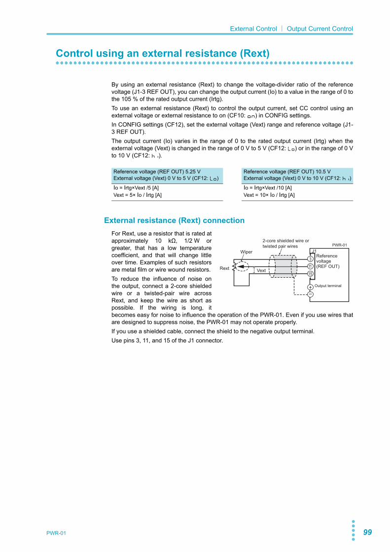
PWR-01 99
External Control| Output Current Control
Control using an external resistance (Rext)
By using an external resistance (Rext) to change the voltage-divider ratio of the referencevoltage (J1-3 REF OUT), you can change the output current (Io) to a value in the range of 0 tothe 105 % of the rated output current (Irtg).To use an external resistance (Rext) to control the output current, set CC control using anexternal voltage or external resistance to on (CF10: ON) in CONFIG settings.In CONFIG settings (CF12), set the external voltage (Vext) range and reference voltage (J1-3 REF OUT).The output current (Io) varies in the range of 0 to the rated output current (Irtg) when theexternal voltage (Vext) is changed in the range of 0 V to 5 V (CF12: LO) or in the range of 0 Vto 10 V (CF12: HI).
External resistance (Rext) connectionFor Rext, use a resistor that is rated atapproximately 10 kΩ, 1/2 W orgreater, that has a low temperaturecoefficient, and that will change littleover time. Examples of such resistorsare metal film or wire wound resistors.To reduce the influence of noise onthe output, connect a 2-core shieldedwire or a twisted-pair wire acrossRext, and keep the wire as short aspossible. If the wiring is long, itbecomes easy for noise to influence the operation of the PWR-01. Even if you use wires thatare designed to suppress noise, the PWR-01 may not operate properly.If you use a shielded cable, connect the shield to the negative output terminal.Use pins 3, 11, and 15 of the J1 connector.
Reference voltage (REF OUT) 5.25 VExternal voltage (Vext) 0 V to 5 V (CF12: LO)
Reference voltage (REF OUT) 10.5 VExternal voltage (Vext) 0 V to 10 V (CF12: HI)
Io = Irtg×Vext /5 [A]Vext = 5× Io / Irtg [A]
Io = Irtg×Vext /10 [A]Vext = 10× Io / Irtg [A]
2-core shielded wire ortwisted pair wires
Output terminal
J1
31115
PWR-01
Rext Vext
WiperReference voltage(REF OUT)

100 PWR-01
Controlling the Output On and Off States
This section explains how to use an external contact to control the output on and off states.
To reduce the influence of noise on the output, connect a 2-core shielded wire or a twisted-pair wire across the external contact, and keep the wire as short as possible. If the wiring islong, it becomes easy for noise to influence the operation of the PWR-01. Even if you usecables that are designed to suppress noise, the PWR-01 may not operate properly.If you use a shielded cable, connect the shield to the negative output terminal.To use an external contact to control the output on and off states, set the appropriate CON-FIG parameter (CF15: ON). Then, select the logic setting from the following two options.• Turn the output on at the falling edge of the LOW signal (CF15: LO)
Output is turned on when a low (0 V to 0.5 V) signal is applied to pin 17 of the J1 connec-tor or the pin is shorted.
• Turn the output on at the rising edge of the HIGH signal (CF15: HI)Output is turned on when a high (4.5 V to 5 V) signal is applied to pin 17 of the J1 connec-tor or the pin is opened.
You can use the CONFIG settings to enable the output-on/ off delay function and soft startand soft stop functions (CF14: ENH).When you are using an external contact to turn the output off, the OUTPUT key on the frontpanel becomes invalid.
Output on/off control is performed by detecting rising edges or falling edges. Because it is nota level detection, if you want to turn on the output at startup, you need to apply a signal sothat an edge is detected.
Controlling the output on and off states (in this example, a HIGH signal is used to turn theoutput on)
WARNING Risk of electric shock.• Ensure that the insulation of external contact (S) and the connected cable is greater
than or equal to the isolation voltage of the PWR-01. For details on the isolation volt-age of each model, see Chap.7 "Specifications" (p.123).
• When using shielded cables for the connection, protect the uncovered sections of the shielded cable by using insulation tubes whose withstand voltage is greater than the PWR-01’s isolation voltage.
On
Off
H = On
L = Off

PWR-01 101
External Control| Controlling the Output On and Off States
External contact connectionUse pins 15 and 17 of the J1 connector.The open-circuit voltage across pins 15 and17 is approximately 5 V. The short-circuitcurrent across pins 5 and 19 is approxi-mately 0.5 mA.Use external contacts that have a contactrating greater than or equal to 0.5 mA at5 Vdc.
If two or more units are floating, and you are using a single external contact to turn output onand off, use a relay or similar device for the external contact signal to isolate the signal trans-mitted to each unit.
For long-distance wiringWhen you are wiring over a great distance,use a small relay and extend the coil side ofthe relay.
2-core shielded wire ortwisted pair wires
Output terminal
J11715
PWR-01
Switch
Switch
Extend this line. Relay
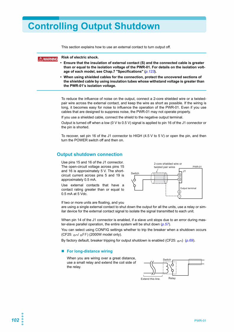
102 PWR-01
Controlling Output Shutdown
This section explains how to use an external contact to turn output off.
To reduce the influence of noise on the output, connect a 2-core shielded wire or a twisted-pair wire across the external contact, and keep the wire as short as possible. If the wiring islong, it becomes easy for noise to influence the operation of the PWR-01. Even if you usecables that are designed to suppress noise, the PWR-01 may not operate properly.If you use a shielded cable, connect the shield to the negative output terminal.Output is turned off when a low (0 V to 0.5 V) signal is applied to pin 16 of the J1 connector orthe pin is shorted.
To recover, set pin 16 of the J1 connector to HIGH (4.5 V to 5 V) or open the pin, and thenturn the POWER switch off and then on.
Output shutdown connectionUse pins 15 and 16 of the J1 connector.The open-circuit voltage across pins 15and 16 is approximately 5 V. The short-circuit current across pins 5 and 19 isapproximately 0.5 mA.Use external contacts that have acontact rating greater than or equal to0.5 mA at 5 Vdc.
If two or more units are floating, and youare using a single external contact to shut down the output for all the units, use a relay or sim-ilar device for the external contact signal to isolate the signal transmitted to each unit.
When pin 14 of the J1 connector is enabled, if a slave unit stops due to an error during mas-ter-slave parallel operation, the entire system will be shut down (p.57).You can select using CONFIG settings whether to trip the breaker when a shutdown occurs(CF25: ON/ OFF) (2000W model only).By factory default, breaker tripping for output shutdown is enabled (CF25: ON) (p.69).
For long-distance wiringWhen you are wiring over a great distance,use a small relay and extend the coil side ofthe relay.
WARNING Risk of electric shock.• Ensure that the insulation of external contact (S) and the connected cable is greater
than or equal to the isolation voltage of the PWR-01. For details on the isolation volt-age of each model, see Chap.7 "Specifications" (p.123).
• When using shielded cables for the connection, protect the uncovered sections of the shielded cable by using insulation tubes whose withstand voltage is greater than the PWR-01’s isolation voltage.
2-core shielded wire ortwisted pair wires
Output terminal
J11615
PWR-01
Switch
Switch
Extend this line. Relay

PWR-01 103
Controlling the Clearing of Alarms
This section explains how to use an external contact to clear alarms.
To reduce the influence of noise on the output, connect a 2-core shielded wire or a twisted-pair wire across the external contact, and keep the wire as short as possible. If the wiring islong, it becomes easy for noise to influence the operation of the PWR-01. Even if you usecables that are designed to suppress noise, the PWR-01 may not operate properly.If you use a shielded cable, connect the shield to the negative output terminal.Alarms are cleared when a low (0 V to 0.5 V) signal is applied to pin 6 of the J1 connector orthe pin is shorted.
Alarm clear connectionUse pins 5 and 6 of the J1 connector.The open-circuit voltage across pins 5and 6 is approximately 5 V. The short-circuit current across pins 5 and 19 isapproximately 0.5 mA.Use external contacts that have a con-tact rating greater than or equal to0.5 mA at 5 Vdc.
If two or more units are floating, and you are using a single external contact to clear alarms,use a relay or similar device for the external contact signal to isolate the signal transmitted toeach unit.
For long-distance wiringWhen you are wiring over a great distance,use a small relay and extend the coil side ofthe relay.
WARNING Risk of electric shock.• Ensure that the insulation of external contact (S) and the connected cable is greater
than or equal to the isolation voltage of the PWR-01. For details on the isolation volt-age of each model, see Chap.7 "Specifications" (p.123).
• When using shielded cables for the connection, protect the uncovered sections of the shielded cable by using insulation tubes whose withstand voltage is greater than the PWR-01’s isolation voltage.
2-core shielded wire ortwisted pair wires
Output terminal
J165
PWR-01
Switch
Switch
Extend this line. Relay

104 PWR-01
External Monitoring
External monitoring of the output voltage and output currentThe J1 connector has monitor outputs for the output voltage and the output current.You can set the monitor output voltage range using CONFIG settings (CF13).
Monitor output ratingOutput impedance: 1 kΩ or less. Maximum output current: Approx. 10 mA
The monitor output signals are used to monitor the DC voltage (mean value). They cannot beused to accurately monitor the AC components (such as ripple and transient response wave-form) of the actual output voltage or current.
Pin no. Signal name Description
J1-5J1-10J1-15
A GND Monitor output common
J1-2 VMON Monitor output of output voltage0 V to approx. 5 V (CF13: LO), 0 V to approx. 10 V (CF13: HI) between 0 V to rated output voltage
J1-12 IMON Monitor output of output current0 V to approx. 5 V (CF13: LO), 0 V to approx. 10 V (CF13: HI) between 0 A to rated output current
CAUTION Shorting VMON and IMON to A GND may damage the PWR-01.
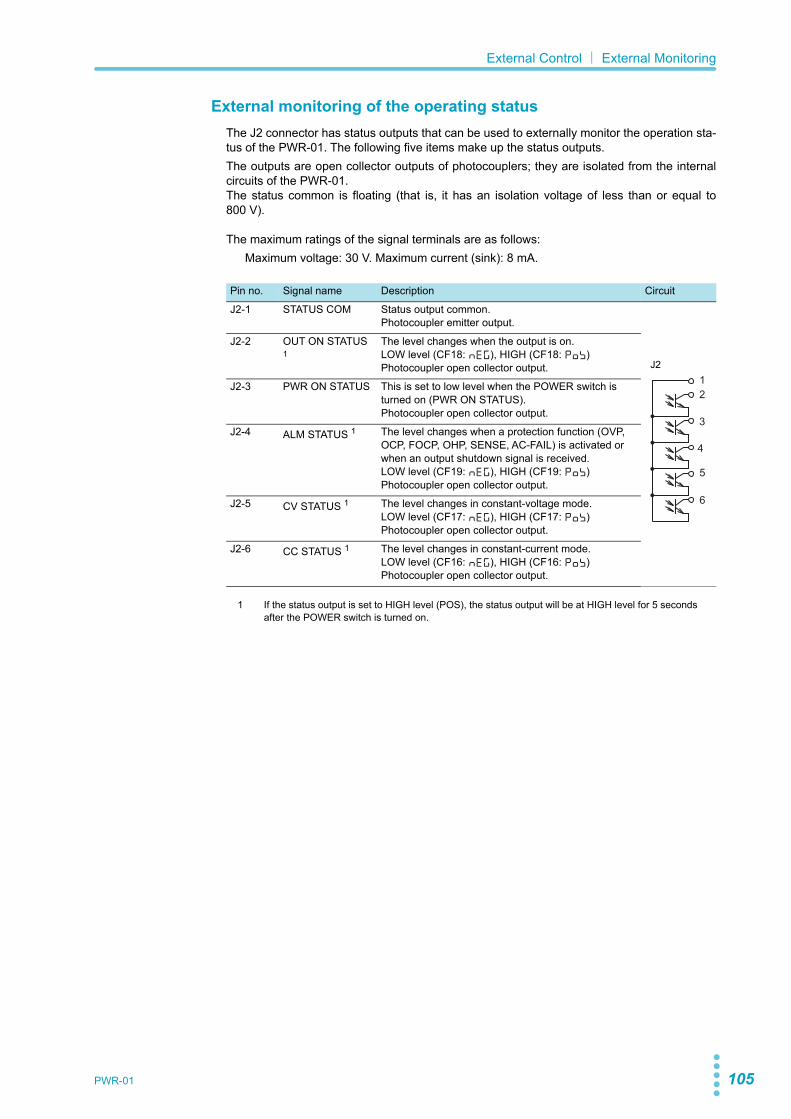
PWR-01 105
External Control| External Monitoring
External monitoring of the operating statusThe J2 connector has status outputs that can be used to externally monitor the operation sta-tus of the PWR-01. The following five items make up the status outputs.The outputs are open collector outputs of photocouplers; they are isolated from the internalcircuits of the PWR-01.The status common is floating (that is, it has an isolation voltage of less than or equal to800 V).
The maximum ratings of the signal terminals are as follows:Maximum voltage: 30 V. Maximum current (sink): 8 mA.
Pin no. Signal name Description Circuit
J2-1 STATUS COM Status output common.Photocoupler emitter output.
J2-2 OUT ON STATUS 1
1 If the status output is set to HIGH level (POS), the status output will be at HIGH level for 5 secondsafter the POWER switch is turned on.
The level changes when the output is on.LOW level (CF18: NEG), HIGH (CF18: POS)Photocoupler open collector output.
J2-3 PWR ON STATUS This is set to low level when the POWER switch is turned on (PWR ON STATUS).Photocoupler open collector output.
J2-4 ALM STATUS 1 The level changes when a protection function (OVP, OCP, FOCP, OHP, SENSE, AC-FAIL) is activated or when an output shutdown signal is received.LOW level (CF19: NEG), HIGH (CF19: POS)Photocoupler open collector output.
J2-5 CV STATUS 1 The level changes in constant-voltage mode.LOW level (CF17: NEG), HIGH (CF17: POS)Photocoupler open collector output.
J2-6 CC STATUS 1 The level changes in constant-current mode.LOW level (CF16: NEG), HIGH (CF16: POS)Photocoupler open collector output.
1
6
5
4
3
2
J2

106 PWR-01
This page is intentionally blank.

Parallel/ Series OperationThis chapter describes the functions ofseries operation and the master-slave par-allel operations as well as the connection,setup, and operation procedures.

108 PWR-01
Master-Slave Parallel Operation
Master-slave parallel operation is a function used to control a whole parallel-connected sys-tem from a master unit. One unit is the master unit, and other PWR-01s connected in parallelare slave units. The master and slave units must all be the same model.You can use master-slave parallel operation to increase the output current (maximum outputcurrent: the rated output current of one unit × the number of units connected in parallel).
The difference in the output voltage and output current between the master unit and the slaveunits is within approximately 5 % of the rating.
Features
The functions of the PWR-01 during master-slave parallel operation are as follows:
Voltage display and current displayThe voltmeter on the master unit displays the voltage. The master unit displays the last volt-age that was set, and the voltmeter on the slave units displays “SLAV.”The master unit’s ammeter displays the total of the currents of all the units connected in par-allel. For slave units, the current display of each slave unit can be set (CF35: OFF/ ON).The maximum current display is 999.9.You can switch the display so that it shows power (p.38). The master unit’s ammeter displaysthe total of the powers of all the units connected in parallel. For slave units, the power displayof each slave unit can be set (CF35: OFF/ ON).
If the number of units in parallel operation (CF44) set on the master unit does not match theactual number of units connected in parallel, the correct current will not be displayed.
External controlThis is only available on the master unit (p.89).
400W model 800W model 1200W model 2000W model
Maximum number of units connected in parallel
Up to three units including the master unit
Up to three units including the master unit
Up to two units including the master unit
Up to two units including the master unit
CAUTION When using a PWR-01 independently or when there are PWR-01s not using parallel opera-tion, disconnect the parallel operation connections. Otherwise, the PWR-01 may not operate properly.
Master unit Slave unit
Example of the panel display during parallel operation(Output current at 20 A, slave unit display set to on)
CV
CC
/W
V
A
ALM RMT LOCK LAN
B CAPRESET
DLY SEQ HBSSVIR
CV
CC
/W
V
A
ALM RMT LOCK LAN
SC2 SC3 LOCKALM CLR SC1 SHIFT
FINE
FINE
REGULATED DC POWER SUPPLY
OUTPUT
VOLTAGE
CURRENT
CONFIG PWR DSPLMEMORY LOCALSET OVP•OCP
CV
CC
/W
V
A
ALM RMT LOCK LAN
B CAPRESET
DLY SEQ HBSSVIR
CV
CC
/W
V
A
ALM RMT LOCK LAN
SC2 SC3 LOCKALM CLR SC1 SHIFT
FINE
FINE
REGULATED DC POWER SUPPLY
OUTPUT
VOLTAGE
CURRENT
CONFIG PWR DSPLMEMORY LOCALSET OVP•OCP

PWR-01 109
Parallel/ Series Operation| Master-Slave Parallel Operation
External monitoring
• External monitoring of the output voltage (VMON) (p.104)This can be monitored from the master unit.
• External monitoring of the output current (IMON) (p.104)You can monitor the output current of the master unit and each slave unit. Use the masterunit to monitor the total output current.
• Status monitors (p.105)You can monitor the status of the following items from the master unit and from the slaveunit: constant-voltage mode (CV STATUS), constant-current mode (CC STATUS), outputon, POWER switch on, and alarms. However, slave units always output the status of con-stant-current mode.
Remote sensingThis is only available on the master unit (p.34).
AlarmsIf an alarm is detected, the units behave as follows:
• Alarm detected on the master unitThe output of each slave unit is turned off, and then the output of the entire system isturned off.
• Alarm detected on a slave unitThe master unit detects the alarm on the slave unit and then turns off the output of theentire system.
Clearing alarmsPress ALM CLR (SHIFT+SET) or apply a LOW level signal (0 V to 0.5 V) to or short pin 6 ofthe J1 connector to clear the alarm state (p.51), and eliminate the cause of the alarm.If a shutdown (SD) or parallel alarm (PRL ARM) is activated, turn off the slave units first andthen the master unit. Eliminate the cause of the alarm, and then turn on the master unit firstand then the slave units (p.113).
CAUTION During parallel operation, do not connect the monitor common cable of the master unit to the monitor common cables of the slave units. If the cables connected to the load are discon-nected, the common cables will be damaged.
CAUTION If an error occurs in a slave unit, the master-slave parallel operation protection (PRL ALM) turns off the output of the entire system. During master-slave parallel operation, connect pin 14 of the J1 connectors of the master unit and slave units.

110 PWR-01
Parallel/ Series Operation| Master-Slave Parallel Operation
Connection
Connecting the signal cablesUse the J1 connector to make the connections for parallel operation.The necessary cables are not included. For details, see "About the J1/ J2 Connectors" (p.90).
Example of connecting two slave units
1 Decide which PWR-01 you will use as the master unit.
2 Connect the J1 connector of the master unit to the J1 connector of thefirst slave unit.
3 If there is a second slave unit, connect the J1 connector of the first slaveunit to that of the second slave unit.
The cable is available as an option (p.148).
J1 J1
PRL ONI SUMPRL OUT+A GNDPRL COMPRL ALMPRL COMP OUT
17
207
10149
19
4
8
13
7
1418
10
OUT ON/OFF CONTI SUMPRL IN+PRL IN-A GNDPRL ALMPRL COMP IN
Master unit Slave unit 1
J117
207
10149
19
OUT ON/OFF CONTI SUMPRL IN+PRL IN-A GNDPRL ALMPRL COMP IN
Slave unit 2

PWR-01 111
Parallel/ Series Operation| Master-Slave Parallel Operation
Connecting the Load
1 Turn off all the PWR-01s that you want to connect in parallel.
2 Remove the OUTPUT terminal covers.
3 Connect the output terminals (positive or negative) of the master unitand the slave units to the chassis terminals.Ground the same polarity output terminals of the master unit and slave units.If you are using the units under floating conditions, do not connect the terminals.
4 Connect the load cables (p.21) to the output terminals of the master unitand the slave units.
5 Connect the load cables of the master unit and slave units to the loadthrough a relay terminal block.Use load cables that have sufficient current capacity. Use load cables of equivalentlength and cross-sectional area to connect each PWR-01 to the relay terminal block,and wire the cables so that they are as short as possible (50 cm or less). Also, makethe connection from the relay terminal block to the load block as short as possible.Wire the J1 connector signal cables and the load cables as far apart as possible.
6 Attach the OUTPUT terminal cover.
WARNING Risk of electric shock. Turn the POWER switch off before you touch the output terminals. Attach the OUTPUT terminal cover after you finish wiring the load.
CAUTION • When you ground the output terminals, be sure to connect the same polarity output terminals (positive or negative) of the master unit and the slave units to the chassis terminals. If you ground different polarity output terminals of the master unit and the slave units, the output will be grounded through the power cable’s GND wire. Not only will this make the output incorrect, it will also damage the chassis connection short bar.
• To prevent oscillation, connect an electrolytic capacitor with a capacitance of a few hundred µF to a few ten thousand µF across the load as necessary. If the wires are long, the wiring inductance and capacitance can cause phase shifting at a level that can not be ignored. This may lead to oscillation.The withstand voltage of the electrolytic capacitor needs to be at least 120 % of the rated output voltage of the PWR-01.
• Twist the positive and negative cables together, and make the connection to the load as short as possible. Oscillation may occur as a result of wiring inductance.
Relay terminal block Load
Master unit
Slave unit 1
Slave unit 2
Output terminal
Chassis terminal
Output terminal
Chassis terminal
Output terminal
Chassis terminal
Load connections for parallel operation (two slave units)(The negative side is connected to the chassis terminal in this example.)
112 PWR-01
Parallel/ Series Operation| Master-Slave Parallel Operation
Setting
Setting the master unit, the slave units, and the number of units in parallel operation (including the master unit)
Turn the output off, and then configure the master unit (CF44: 2 or 3) and the slave units(CF44: SLAV). On the master unit, set the number of units in parallel operation (CF44: 2 or3).By factory default, the PWR-01 is set to independent operation (CF44: 1).Turn the POWER switch off and on to enable the setting.
Be sure to set the number of units in parallel operation (CF44) to the actual number of units. Ifthis parameter is incorrect, settings such as those for the current and the overcurrent protec-tion (OCP) cannot be set correctly, and the measured current will not be displayed correctly.
Setting the voltage and currentUse the master unit to set the voltage and current (p.108).The current that is output is the sum of the currents of the master unit and the slave units.When you set the number of units in parallel operation (CF44) in CONFIG settings, the maxi-mum output current (105 % of the rated output current of a single unit × the number of units inparallel) is set. The value is displayed when the PWR-01 is showing the setting display (whenthe SET key is lit). The last voltage that was set on the master unit is used. When you pressOUTPUT, the set voltage and current are output. You can set the voltage and current to anyvalues.
Setting the overvoltage protection (OVP) and overcurrent protec-tion (OCP) of the master unit
In parallel operation, set the overvoltage protection (OVP) and overcurrent protection (OCP)of the master unit (p.52).When you set the number of units in parallel operation (CF44) in CONFIG settings, the maxi-mum overcurrent protection value (112 % of the rated output current of a single unit × thenumber of units in parallel) is set. The value is displayed when the PWR-01 is showing theOVP/OCP setting display (when the OVP•OCP key is lit). The last overvoltage protectionvalue that was set on the master unit is used.
Breaker trip setting for protection function (OVP/ OCP/ FOCP/ SD/ PRL ALM) activation (2000W model only)
In parallel operation, you can select using CONFIG settings whether to trip the breaker (turnoff the POWER switch) when a protection function (OVP/ OCP/ FOCP/ SD/ PRL ALM) isactivated (CF25: OFF/ON) (p.69). The factory default setting is ON.The master unit setting is not applied to slave units. Set it in the master unit and slave units.

PWR-01 113
Parallel/ Series Operation| Master-Slave Parallel Operation
Starting master-slave parallel operation
Turning on the POWER switch
1 Turn on the master unit’s POWER switch.
2 Turn off the POWER switch of each slave unit.
3 Operate the master unit normally.You cannot perform panel operations on the slave units. Turn output on and off fromthe master unit.
Turning the POWER switch off
1 Turn off the POWER switch of each slave unit.
2 Turn off the master unit’s POWER switch.
CAUTION After you turn the POWER switch off, wait at least 10 seconds after the panel display turns off before you turn the POWER switch back on. Repeatedly turning the POWER switch on and off at short intervals can cause damage to the inrush current limiter. Furthermore, this will shorten the service life of the POWER switch, internal input fuse, and other components.
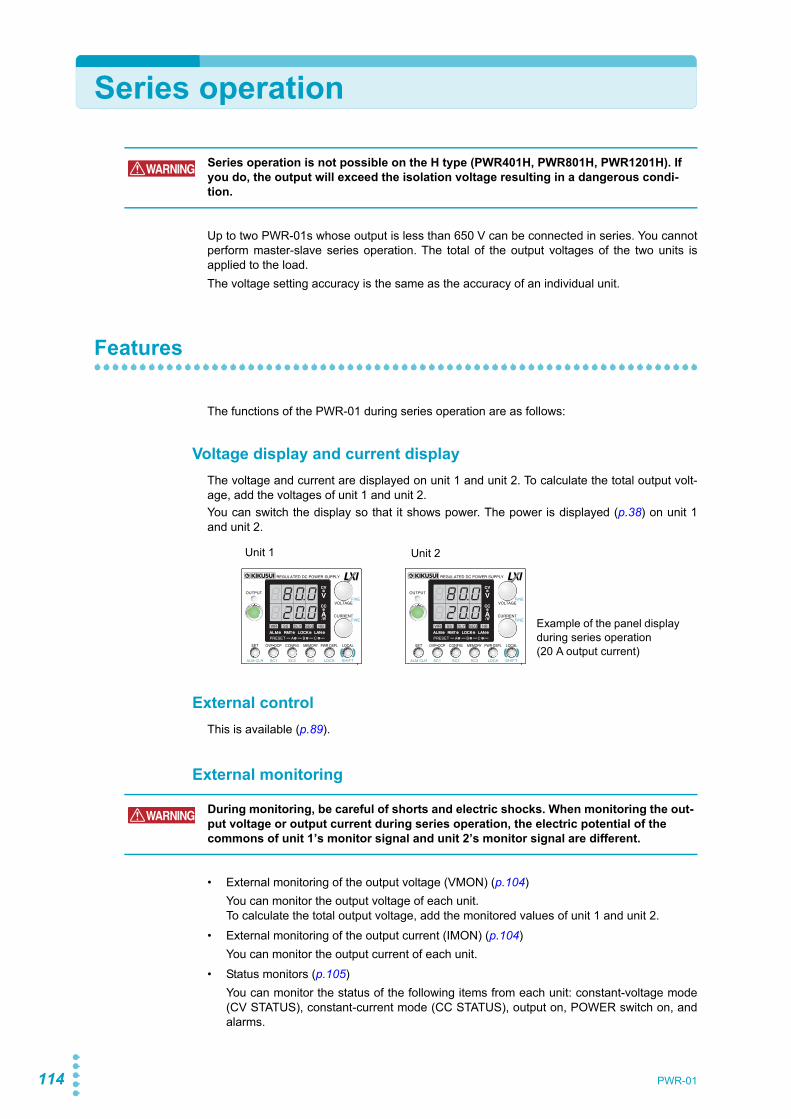
114 PWR-01
Series operation
Up to two PWR-01s whose output is less than 650 V can be connected in series. You cannotperform master-slave series operation. The total of the output voltages of the two units isapplied to the load.The voltage setting accuracy is the same as the accuracy of an individual unit.
Features
The functions of the PWR-01 during series operation are as follows:
Voltage display and current displayThe voltage and current are displayed on unit 1 and unit 2. To calculate the total output volt-age, add the voltages of unit 1 and unit 2.You can switch the display so that it shows power. The power is displayed (p.38) on unit 1and unit 2.
External controlThis is available (p.89).
External monitoring
• External monitoring of the output voltage (VMON) (p.104)You can monitor the output voltage of each unit.To calculate the total output voltage, add the monitored values of unit 1 and unit 2.
• External monitoring of the output current (IMON) (p.104)You can monitor the output current of each unit.
• Status monitors (p.105)You can monitor the status of the following items from each unit: constant-voltage mode(CV STATUS), constant-current mode (CC STATUS), output on, POWER switch on, andalarms.
WARNING Series operation is not possible on the H type (PWR401H, PWR801H, PWR1201H). If you do, the output will exceed the isolation voltage resulting in a dangerous condi-tion.
Unit 1 Unit 2
Example of the panel display during series operation(20 A output current)
CV
CC
/W
V
A
ALM RMT LOCK LAN
B CAPRESET
DLY SEQ HBSSVIR
CV
CC
/W
V
A
ALM RMT LOCK LAN
SC2 SC3 LOCKALM CLR SC1 SHIFT
FINE
FINE
REGULATED DC POWER SUPPLY
OUTPUT
VOLTAGE
CURRENT
CONFIG PWR DSPLMEMORY LOCALSET OVP•OCP
CV
CC
/W
V
A
ALM RMT LOCK LAN
B CAPRESET
DLY SEQ HBSSVIR
CV
CC
/W
V
A
ALM RMT LOCK LAN
SC2 SC3 LOCKALM CLR SC1 SHIFT
FINE
FINE
REGULATED DC POWER SUPPLY
OUTPUT
VOLTAGE
CURRENT
CONFIG PWR DSPLMEMORY LOCALSET OVP•OCP
WARNING During monitoring, be careful of shorts and electric shocks. When monitoring the out-put voltage or output current during series operation, the electric potential of the commons of unit 1’s monitor signal and unit 2’s monitor signal are different.

PWR-01 115
Parallel/ Series Operation| Series operation
Remote sensing
To perform remote sensing, connect the PWR-01s in series, and then connect the sensingcables to them as shown in the following figure (p.34).
AlarmsAll alarms will be detected during series operation.You can select whether to automatically turn on or off the output when the cause of the alarmis removed using a CONFIG setting (CF20: AUTO/ SAFE) (AC-FAIL only).
Clearing alarmsPress ALM CLR (SHIFT+SET) or apply a low level signal (0 V to 0.5 V) to or short pin 6 of theJ1 connector to clear the alarm state (p.51), and eliminate the cause of the alarm.If a shutdown (SD) or parallel alarm (PRL ARM) is activated, turn off the POWER switch onunit 1 and unit 2. Eliminate the cause of the alarm, and then turn on the two units (p.117).
CAUTION • If the sensing cables are not connected properly, the load may be exposed to excessive voltage, and the PWR-01s may be damaged.
• To prevent oscillation, connect an electrolytic capacitor with a capacitance of a few hundred µF to a few ten thousand µF across the load as necessary. If the wires are long, the wiring inductance and capacitance can cause phase shifting at a level that can not be ignored. This may lead to oscillation.The withstand voltage of the electrolytic capacitor needs to be at least 120 % of the total rated output voltage of the PWR-01s connected in series.
++
––
Capacitor
Connect an electrolytic capacitor across the load as necessary.
Load
+S
-S
+S
-S
Output terminal
Chassis terminal
Sensing terminal
Unit 1
Unit 2Output terminal
Chassis terminal
Sensing terminalConnecting the sensing cables during series operation

116 PWR-01
Parallel/ Series Operation| Series operation
Connection
Connecting the Load
Connect the load as shown below.
1 Turn off all the PWR-01s that you want to connect in series.
2 Remove the OUTPUT terminal covers.
3 Connect the output terminal (positive or negative) of unit 1 or unit 2 tothe chassis terminal.
4 Use load cables to connect unit 1 and unit 2 to the load or relay terminalblock.Use load cables that have sufficient current capacity (p.21). Wire the load cables sothat they are as short as possible. If the voltage drop in the load cable is large, the dif-ference in electric potential between power supply units and the load regulationbecome large.
5 Connect the cables to the output terminals of unit 1 and unit 2.
6 Attach the OUTPUT terminal cover.
WARNING Risk of electric shock. Turn the POWER switch off before you touch the output termi-nals. Attach the OUTPUT terminal cover after you finish wiring the load.
CAUTION To prevent oscillation, connect an electrolytic capacitor with a capacitance of a few hundred µF to a few ten thousand µF across the load as necessary. If the wires are long, the wiring inductance and capacitance can cause phase shifting at a level that can not be ignored. This may lead to oscillation.The withstand voltage of the electrolytic capacitor needs to be at least 120 % of the total rated output voltage of the PWR-01s connected in series.
Load or relay terminal blockUnit 1
Unit 2
Output terminal
Chassis terminal
Output terminal
Chassis terminalLoad connection in series operation(In this example, the negative terminal of unit 2 is connected to the chassis terminal.)
PWR-01 117
Parallel/ Series Operation| Series operation
Setting
Setting the voltage and currentSet the voltage and current on each unit. The voltage that is output is the total of the voltagesof the two units. Set the current to the same value on the two units.
Setting the overvoltage protection (OVP) and overcurrent protec-tion (OCP)
In series operation, you have to set the overvoltage protection (OVP) and overcurrent protec-tion (OCP) on both units (p.52). Specify the same values on the two units.
Starting series operation
Turning the POWER switch on and offTurn the POWER switch on unit 1 and unit 2 on or off.
Turning the output on/offPress OUTPUT on unit 1 and unit 2 to turn the output on or off.
CAUTION After you turn the POWER switch off, wait at least 10 seconds after the fan stops before you turn the POWER switch back on. Repeatedly turning the POWER switch on and off at short intervals can cause damage to the inrush current limiter. Furthermore, this will shorten the service life of the POWER switch, internal input fuse, and other components.

118 PWR-01
This page is intentionally blank.

MaintenanceThis chapter explains how to perform cali-bration.

120 PWR-01
Calibration
The product is calibrated before shipment. To maintain long-term reliable performance, werecommend periodic calibration.To have your product calibrated, contact your Kikusui distributor or agent.If you are going to calibrate the product, follow the procedure below. All the calibration param-eters of this product are listed.
Calibration overview
The following eight parameters can be calibrated.Be sure to calibrate both the offset and full scale values.• Output voltage offset (10 %) • Output voltage full scale (100 %)• Voltmeter offset (0 %) • Voltmeter full scale (100 %)• Output current offset (10 %) • Output current full scale (100 %)• Ammeter offset (0 %) • Ammeter full scale (100 %)
Required devices• DC voltmeter (DVM) with a measurement accuracy of 0.02 % or more
• Shunt resistor
EnvironmentPerform calibration in the following environment.
• Temperature: 23 °C ± 5 °C
• Humidity: 80 %rh or less
To minimize the calibration error due to initial drift, warm up the PWR-01 for at least30 minutes before calibration. In addition, warm up the DVM and shunt resistor for as long asis necessary.
ModelRecommended shunt resistor
Rating Tolerance
PWR401L 50 A/ 100 mV (2.00 mΩ)
<±0.1 %
PWR401ML 20 A/ 100 mV (5.00 mΩ)
PWR401MH 10 A/ 100 mV (10.00 mΩ)
PWR401H 2 A/ 100 mV (50.00 mΩ)
PWR801L 100 A/ 100 mV (1.00 mΩ)
PWR801ML 50 A/ 100 mV (2.00 mΩ)
PWR801MH 20 A/ 100 mV (5.00 mΩ)
PWR801H 5 A/ 100 mV (20.00 mΩ)
PWR1201L 200 A/ 50 mV (0.25 mΩ)
PWR1201ML 100 A/ 100 mV (1.00 mΩ)
PWR1201MH 20 A/ 100 mV (5.00 mΩ)
PWR1201H 10 A/ 100 mV (10.00 mΩ)
PWR2001L 200 A/ 50 mV (0.25 mΩ)
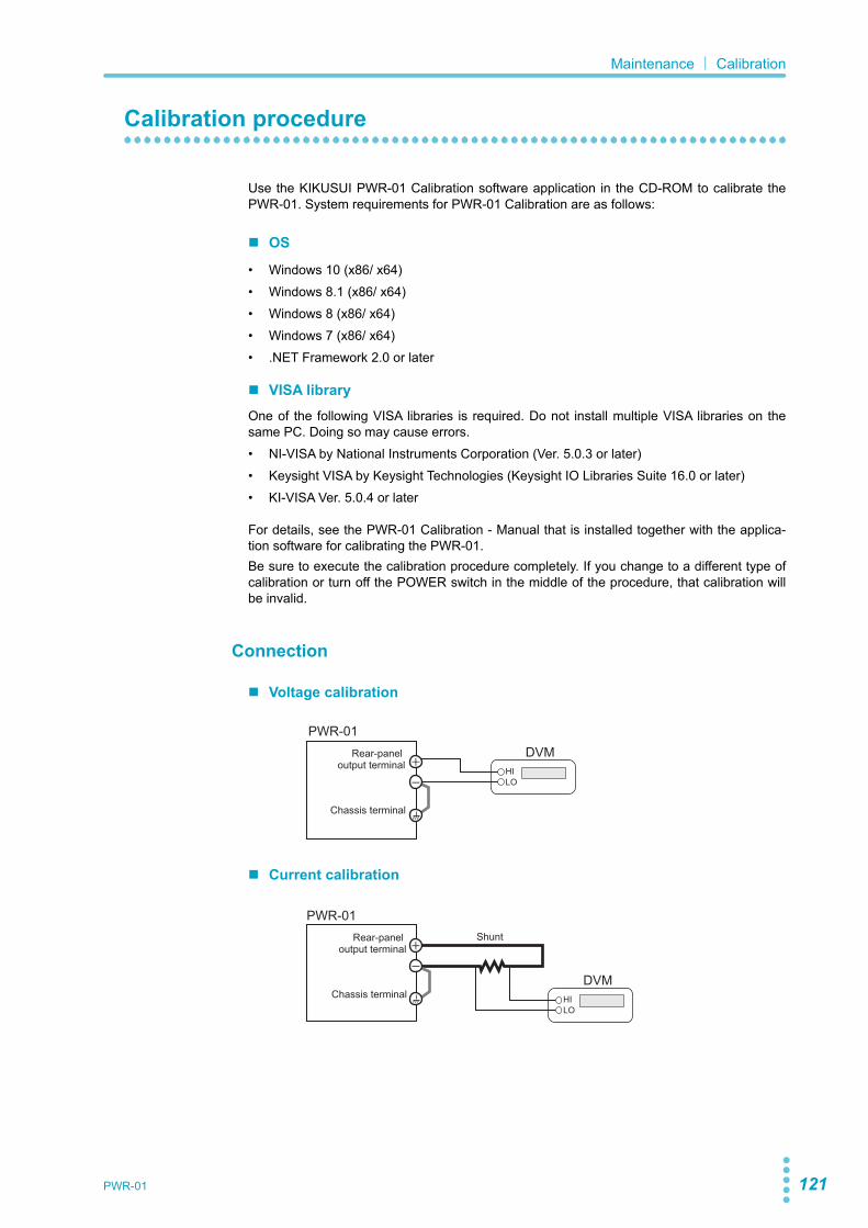
PWR-01 121
Maintenance| Calibration
Calibration procedure
Use the KIKUSUI PWR-01 Calibration software application in the CD-ROM to calibrate thePWR-01. System requirements for PWR-01 Calibration are as follows:
OS
• Windows 10 (x86/ x64)• Windows 8.1 (x86/ x64)• Windows 8 (x86/ x64)• Windows 7 (x86/ x64)• .NET Framework 2.0 or later
VISA libraryOne of the following VISA libraries is required. Do not install multiple VISA libraries on thesame PC. Doing so may cause errors.• NI-VISA by National Instruments Corporation (Ver. 5.0.3 or later)• Keysight VISA by Keysight Technologies (Keysight IO Libraries Suite 16.0 or later)• KI-VISA Ver. 5.0.4 or later
For details, see the PWR-01 Calibration - Manual that is installed together with the applica-tion software for calibrating the PWR-01.Be sure to execute the calibration procedure completely. If you change to a different type ofcalibration or turn off the POWER switch in the middle of the procedure, that calibration willbe invalid.
Connection
Voltage calibration
Current calibration
DVMPWR-01
HILO
Rear-panel output terminal
Chassis terminal
Shunt
DVM
PWR-01
HILO
Rear-panel output terminal
Chassis terminal
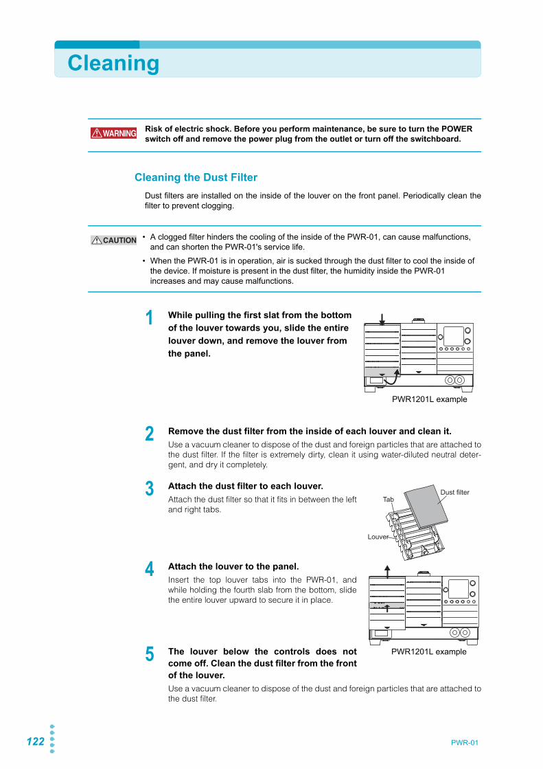
122 PWR-01
Cleaning
Cleaning the Dust FilterDust filters are installed on the inside of the louver on the front panel. Periodically clean thefilter to prevent clogging.
1 While pulling the first slat from the bottom of the louver towards you, slide the entire louver down, and remove the louver from the panel.
2 Remove the dust filter from the inside of each louver and clean it.Use a vacuum cleaner to dispose of the dust and foreign particles that are attached tothe dust filter. If the filter is extremely dirty, clean it using water-diluted neutral deter-gent, and dry it completely.
3 Attach the dust filter to each louver.Attach the dust filter so that it fits in between the leftand right tabs.
4 Attach the louver to the panel.Insert the top louver tabs into the PWR-01, andwhile holding the fourth slab from the bottom, slidethe entire louver upward to secure it in place.
5 The louver below the controls does notcome off. Clean the dust filter from the frontof the louver.Use a vacuum cleaner to dispose of the dust and foreign particles that are attached tothe dust filter.
WARNING Risk of electric shock. Before you perform maintenance, be sure to turn the POWER switch off and remove the power plug from the outlet or turn off the switchboard.
CAUTION • A clogged filter hinders the cooling of the inside of the PWR-01, can cause malfunctions, and can shorten the PWR-01's service life.
• When the PWR-01 is in operation, air is sucked through the dust filter to cool the inside of the device. If moisture is present in the dust filter, the humidity inside the PWR-01 increases and may cause malfunctions.
PWR1201L example
Dust filter
Louver
Tab
PWR1201L example

SpecificationsThis chapter contains the specificationsand gives the dimensions of the PWR-01.

124 PWR-01
Specifications|
Unless specified otherwise, the specifications are for the following settings and conditions.
• Loads are pure resistive loads.• The product is warmed up for at least 30 minutes (with current flowing).• After warm-up, the product must be calibrated correctly in a 23 °C ± 5 °C environment
according to the appropriate calibration procedure.• Values indicated by “TYP” are typical values. They are not guaranteed performance val-
ues.• Values indicated by “rating” are ratings.• Values indicated by “reading” are readings.• Values indicated by "f.s." are full scale values.• The PWR-01 operates over a wide range of output voltage and output current within rated
output power. However, the current that can be output with rated output voltage and thevoltage that can be output with rated output current are limited by the rated output power.
• The current that can be output with rated output voltage and the voltage that can be out-put with rated output current are as follows.Maximum output current with rated output voltage = Rated output power/ rated outputvoltage.Maximum output voltage with rated output current = Rated output power/ rated output cur-rent.
• Rated load and no load are defined as follows:In constant-voltage mode (when the output current is set to a value greater than or equalto the maximum output current with rated output voltage)
Rated load: Refers to a resistive load that, when the rated output voltage is applied,makes the flowing current 95 % to 100 % of the maximum output currentwith rated output voltage.
No load: Refers to a load through which no output current flows. In other words,refers to an open load (no load being connected).
In constant-current mode (when the output voltage is set to a value greater than or equalto the maximum output voltage with rated output current)
Rated load:Refers to a resistive load that, when the rated output current flows, makesthe voltage drop to 95 % to 100 % of the maximum output voltage withrated output current.Including the voltage drop in the load cables, the PWR-01 output voltagemust not exceed the maximum output voltage with rated output current.
No load: Refers to a resistive load that, when the rated output current flows, makesthe voltage drop to 10 % of the maximum output voltage with rated outputcurrent or 1 V whichever is higher.
• The specifications of the PWR-01 apply to the rear-panel output terminals.

PWR-01 125
400W model
This section provides the specifications specific to the 400W model. For specifications com-mon to all models (Protection functions, Signal output and input, Control functions, Otherfunctions, Operation display, Interface, and General), see "Common specifications"(p.137).
AC input
PWR401L PWR401ML PWR401MH PWR401H
Nominal input rating 100 Vac to 240 Vac, 50 Hz to 60 Hz, single phase
Input voltage range 85 Vac to 265 Vac
Input frequency range 47 Hz to 63 Hz
Current (TYP)1
1. At the rated output power for the rated output current.
100 Vac 5.6 A
200 Vac 2.8 A
Inrush current 25 A or less
Power (MAX) 2
2. 100 Vac, at the rated output power.
560 VA
Power factor (TYP) 1 0.99 (input voltage: 100 V), 0.97 (input voltage: 200 V)
Efficiency (TYP)1 75 %
Output hold time 2 20 ms or more
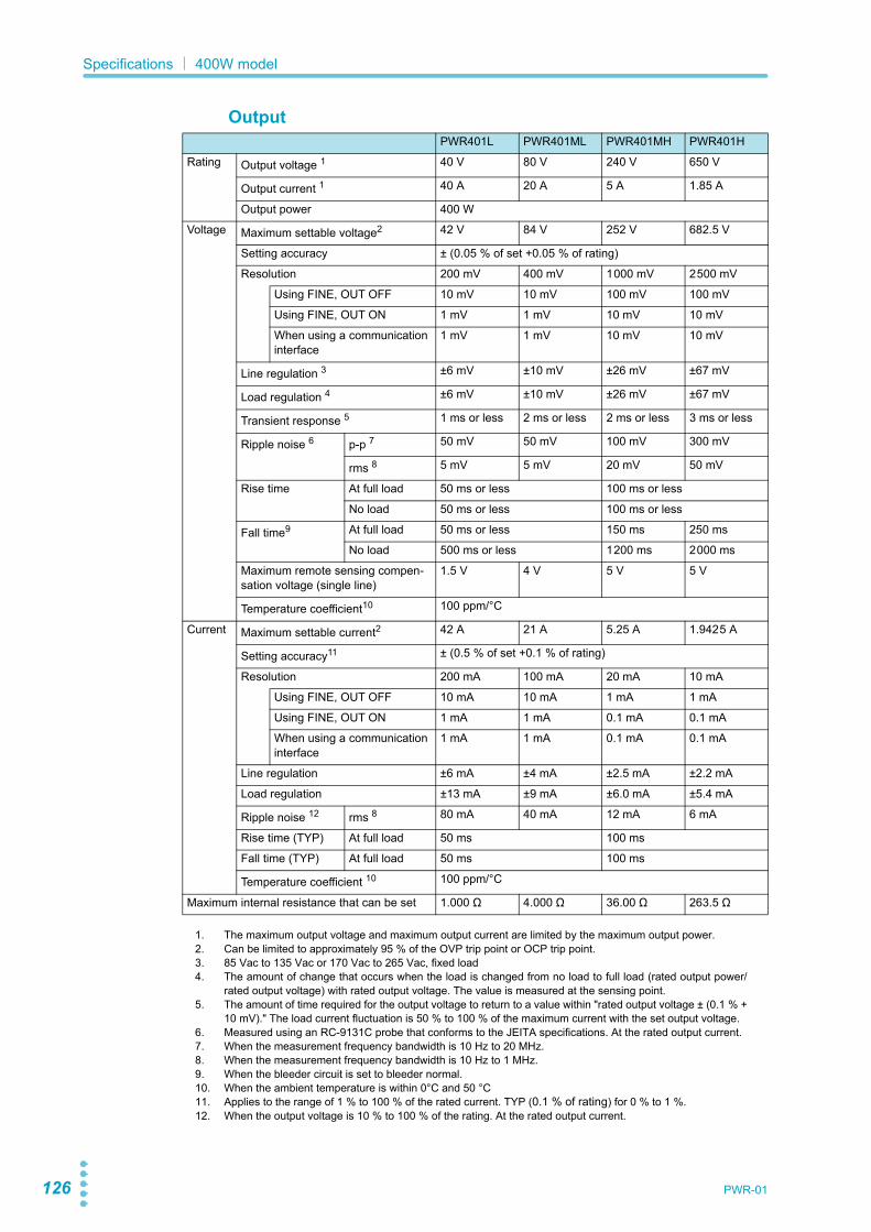
126 PWR-01
Specifications| 400W model
OutputPWR401L PWR401ML PWR401MH PWR401H
Rating Output voltage 1 40 V 80 V 240 V 650 V
Output current 1 40 A 20 A 5 A 1.85 A
Output power 400 W
Voltage Maximum settable voltage2 42 V 84 V 252 V 682.5 V
Setting accuracy ± (0.05 % of set +0.05 % of rating)
Resolution 200 mV 400 mV 1000 mV 2500 mV
Using FINE, OUT OFF 10 mV 10 mV 100 mV 100 mV
Using FINE, OUT ON 1 mV 1 mV 10 mV 10 mV
When using a communication interface
1 mV 1 mV 10 mV 10 mV
Line regulation 3 ±6 mV ±10 mV ±26 mV ±67 mV
Load regulation 4 ±6 mV ±10 mV ±26 mV ±67 mV
Transient response 5 1 ms or less 2 ms or less 2 ms or less 3 ms or less
Ripple noise 6 p-p 7 50 mV 50 mV 100 mV 300 mV
rms 8 5 mV 5 mV 20 mV 50 mV
Rise time At full load 50 ms or less 100 ms or less
No load 50 ms or less 100 ms or less
Fall time9 At full load 50 ms or less 150 ms 250 ms
No load 500 ms or less 1200 ms 2000 ms
Maximum remote sensing compen-sation voltage (single line)
1.5 V 4 V 5 V 5 V
Temperature coefficient10 100 ppm/°C
Current Maximum settable current2 42 A 21 A 5.25 A 1.9425 A
Setting accuracy11 ± (0.5 % of set +0.1 % of rating)
Resolution 200 mA 100 mA 20 mA 10 mA
Using FINE, OUT OFF 10 mA 10 mA 1 mA 1 mA
Using FINE, OUT ON 1 mA 1 mA 0.1 mA 0.1 mA
When using a communication interface
1 mA 1 mA 0.1 mA 0.1 mA
Line regulation ±6 mA ±4 mA ±2.5 mA ±2.2 mA
Load regulation ±13 mA ±9 mA ±6.0 mA ±5.4 mA
Ripple noise 12 rms 8 80 mA 40 mA 12 mA 6 mA
Rise time (TYP) At full load 50 ms 100 ms
Fall time (TYP) At full load 50 ms 100 ms
Temperature coefficient 10 100 ppm/°C
Maximum internal resistance that can be set 1.000 Ω 4.000 Ω 36.00 Ω 263.5 Ω
1. The maximum output voltage and maximum output current are limited by the maximum output power.2. Can be limited to approximately 95 % of the OVP trip point or OCP trip point.3. 85 Vac to 135 Vac or 170 Vac to 265 Vac, fixed load4. The amount of change that occurs when the load is changed from no load to full load (rated output power/
rated output voltage) with rated output voltage. The value is measured at the sensing point.5. The amount of time required for the output voltage to return to a value within "rated output voltage ± (0.1 % +
10 mV)." The load current fluctuation is 50 % to 100 % of the maximum current with the set output voltage.6. Measured using an RC-9131C probe that conforms to the JEITA specifications. At the rated output current.7. When the measurement frequency bandwidth is 10 Hz to 20 MHz.8. When the measurement frequency bandwidth is 10 Hz to 1 MHz.9. When the bleeder circuit is set to bleeder normal.10. When the ambient temperature is within 0°C and 50 °C11. Applies to the range of 1 % to 100 % of the rated current. TYP (0.1 % of rating) for 0 % to 1 %.12. When the output voltage is 10 % to 100 % of the rating. At the rated output current.

PWR-01 127
Specifications| 400W model
Display function
Outline drawing
PWR-01 series 400W model outline drawing Unit mm (inches)
PWR401L PWR401ML PWR401MH PWR401H
Voltage display
Maximum display 99.99 999.9
Display accuracy ± (0.2 % of reading + 5 digit)
Current display
Maximum display 99.99 9.999
Display accuracy ± (0.5 % of reading + 8 digit)
Power display The PWR DSPL LED lights in red.
Maximum display 9999
Display accuracy Displays the result of multiplying the current and voltage. The display is toggled with the voltage or current display.
4- 1 8 (Rubber foot diameter)
MAX420 (16.54) MAX20 (0.79)
MAX
140
(5.5
1)
350 (13.78)
31 (1.22) 272.5 (10.73) 46.5 (1.83)
71 (2.80)
50 (1
.97)
10.5
(0
.41)
10.5
(0
.41)
124
(4.8
8)
Four M3 screw holes (max. screw insertion depth: 5 mm (0.20 inch)

128 PWR-01
800W model
This section provides the specifications specific to the 800W model. For specifications com-mon to all models (Protection functions, Signal output and input, Control functions, Otherfunctions, Operation display, Interface, and General), see "Common specifications"(p.137).
AC input
PWR801L PWR801ML PWR801MH PWR801H
Nominal input rating 100 Vac to 240 Vac, 50 Hz to 60 Hz, single phase
Input voltage range 85 Vac to 265 Vac
Input frequency range 47 Hz to 63 Hz
Current (TYP)1
1. At the rated output power for the rated output current.
100 Vac 11.2 A
200 Vac 5.6 A
Inrush current 50 A or less
Power (MAX) 2
2. 100 Vac, at the rated output power.
1120 VA
Power factor (TYP) 1 0.99 (input voltage: 100 V), 0.97 (input voltage: 200 V)
Efficiency (TYP)1 75 %
Output hold time 2 20 ms or more

PWR-01 129
Specifications| 800W model
OutputPWR801L PWR801ML PWR801MH PWR801H
Rating Output voltage 1 40 V 80 V 240 V 650 V
Output current 1 80 A 40 A 10 A 3.70 A
Output power 800 W
Voltage Maximum settable voltage2 42 V 84 V 252 V 682.5 V
Setting accuracy ± (0.05 % of set +0.05 % of rating)
Resolution 200 mV 400 mV 1000 mV 2500 mV
Using FINE, OUT OFF 10 mV 10 mV 100 mV 100 mV
Using FINE, OUT ON 1 mV 1 mV 10 mV 10 mV
When using a communication interface
1 mV 1 mV 10 mV 10 mV
Line regulation 3 ±6 mV ±10 mV ±26 mV ±67 mV
Load regulation 4 ±6 mV ±10 mV ±26 mV ±67 mV
Transient response 5 1 ms or less 2 ms or less 2 ms or less 3 ms or less
Ripple noise 6 p-p 7 50 mV 50 mV 100 mV 300 mV
rms 8 5 mV 5 mV 20 mV 50 mV
Rise time At full load 50 ms or less 100 ms or less
No load 50 ms or less 100 ms or less
Fall time9 At full load 50 ms or less 150 ms 250 ms
No load 500 ms or less 1200 ms 2000 ms
Maximum remote sensing compen-sation voltage (single line)
1.5 V 4 V 5 V 5 V
Temperature coefficient10 100 ppm/°C
Current Maximum settable current2 84 A 42 A 10.5 A 3.885 A
Setting accuracy11 ± (0.5 % of set +0.1 % of rating)
Resolution 400 mA 200 mA 40 mA 20 mA
Using FINE, OUT OFF 10 mA 10 mA 10 mA 1 mA
Using FINE, OUT ON 1 mA 1 mA 1 mA 0.1 mA
When using a communication interface
1 mA 1 mA 1 mA 0.1 mA
Line regulation ±10 mA ±6 mA ±3 mA ±2.4 mA
Load regulation ±21 mA ±13 mA ±7.0 mA ±5.7 mA
Ripple noise 12 rms 8 160 mA 80 mA 24 mA 12 mA
Rise time (TYP) At full load 50 ms 100 ms
Fall time (TYP) At full load 50 ms 100 ms
Temperature coefficient 10 100 ppm/°C
Maximum internal resistance that can be set 0.500 Ω 2.000 Ω 18.00 Ω 131.8 Ω
1. The maximum output voltage and maximum output current are limited by the maximum output power.2. Can be limited to approximately 95 % of the OVP trip point or OCP trip point.3. 85 Vac to 135 Vac or 170 Vac to 265 Vac, fixed load4. The amount of change that occurs when the load is changed from no load to full load (rated output power/
rated output voltage) with rated output voltage. The value is measured at the sensing point.5. The amount of time required for the output voltage to return to a value within "rated output voltage ± (0.1 % +
10 mV)." The load current fluctuation is 50 % to 100 % of the maximum current with the set output voltage.6. Measured using an RC-9131C probe that conforms to the JEITA specifications. At the rated output current.7. When the measurement frequency bandwidth is 10 Hz to 20 MHz.8. When the measurement frequency bandwidth is 10 Hz to 1 MHz.9. When the bleeder circuit is set to bleeder normal.10. When the ambient temperature is within 0°C and 50 °C11. Applies to the range of 1 % to 100 % of the rated current. TYP (0.1 % of rating) for 0 % to 1 %.12. When the output voltage is 10 % to 100 % of the rating. At the rated output current.

130 PWR-01
Specifications| 800W model
Display function
Outline drawing
PWR-01 series 800W model outline drawing Unit mm (inches)
PWR801L PWR801ML PWR801MH PWR801H
Voltage dis-play
Maximum display 99.99 999.9
Display accuracy ± (0.2 % of reading + 5 digit)
Current dis-play
Maximum display 99.99 9.999
Display accuracy ± (0.5 % of reading + 8 digit)
Power display The PWR DSPL LED lights in red.
Maximum display 9999
Display accuracy Displays the result of multiplying the current and voltage. The display is toggled with the voltage or current display.
4-Ø18 (Rubber foot diameter)
MAX
15
(0.5
9)
142.5 (5.61)
121.
5 (4
.78)
MAX420 (16.54) MAX20 (0.79)350 (13.78)
31 (1.22) 272.5 (10.73) 46.5 (1.83) 10.5
(0
.41)
10.5
(0
.41)
Four M3 screw holes (max. screw insertion depth: 5 mm (0.20 inch)
MAX
150
(5.9
1)12
4 (4
.88)
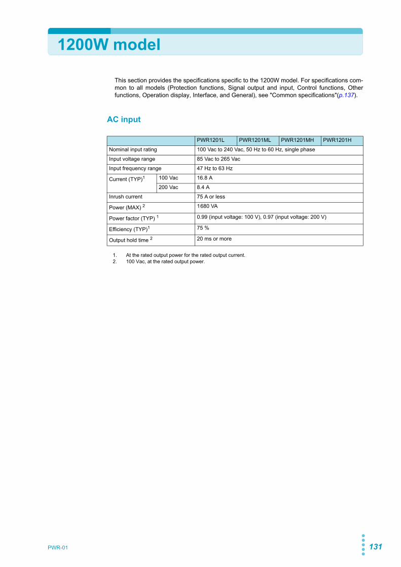
PWR-01 131
1200W model
This section provides the specifications specific to the 1200W model. For specifications com-mon to all models (Protection functions, Signal output and input, Control functions, Otherfunctions, Operation display, Interface, and General), see "Common specifications"(p.137).
AC input
PWR1201L PWR1201ML PWR1201MH PWR1201H
Nominal input rating 100 Vac to 240 Vac, 50 Hz to 60 Hz, single phase
Input voltage range 85 Vac to 265 Vac
Input frequency range 47 Hz to 63 Hz
Current (TYP)1
1. At the rated output power for the rated output current.
100 Vac 16.8 A
200 Vac 8.4 A
Inrush current 75 A or less
Power (MAX) 2
2. 100 Vac, at the rated output power.
1680 VA
Power factor (TYP) 1 0.99 (input voltage: 100 V), 0.97 (input voltage: 200 V)
Efficiency (TYP)1 75 %
Output hold time 2 20 ms or more

132 PWR-01
Specifications| 1200W model
OutputPWR1201L PWR1201ML PWR1201MH PWR1201H
Rating Output voltage 1 40 V 80 V 240 V 650 V
Output current 1 120 A 60 A 15.0 A 5.55 A
Output power 1200 W
Voltage Maximum settable voltage2 42 V 84 V 252 V 682.5 V
Setting accuracy ± (0.05 % of set +0.05 % of rating)
Resolution 200 mV 400 mV 1000 mV 2500 mV
Using FINE, OUT OFF 10 mV 10 mV 100 mV 100 mV
Using FINE, OUT ON 1 mV 1 mV 10 mV 10 mV
When using a communication interface
1 mV 1 mV 10 mV 10 mV
Line regulation 3 ±6 mV ±10 mV ±26 mV ±67 mV
Load regulation 4 ±6 mV ±10 mV ±26 mV ±67 mV
Transient response 5 1 ms or less 2 ms or less 2 ms or less 3 ms or less
Ripple noise 6 p-p 7 50 mV 50 mV 100 mV 300 mV
rms 8 5 mV 5 mV 20 mV 50 mV
Rise time At full load 50 ms or less 100 ms or less
No load 50 ms or less 100 ms or less
Fall time9 At full load 50 ms or less 150 ms 250 ms
No load 500 ms or less 1200 ms 2000 ms
Maximum remote sensing compen-sation voltage (single line)
1.5 V 4 V 5 V 5 V
Temperature coefficient10 100 ppm/°C
Current Maximum settable current2 126 A 63 A 15.75 A 5.8275 A
Setting accuracy11 ± (0.5 % of set +0.1 % of rating)
Resolution 600 mA 300 mA 60 mA 30 mA
Using FINE, OUT OFF 100 mA 10 mA 10 mA 1 mA
Using FINE, OUT ON 10 mA 1 mA 1 mA 0.1 mA
When using a communication interface
10 mA 1 mA 1 mA 0.1 mA
Line regulation ±14 mA ±8 mA ±3.5 mA ±2.6 mA
Load regulation ±29 mA ±17 mA ±8.0 mA ±6.1 mA
Ripple noise 12 rms 8 240 mA 120 mA 36 mA 18 mA
Rise time (TYP) At full load 50 ms 100 ms
Fall time (TYP) At full load 50 ms 100 ms
Temperature coefficient 10 100 ppm/°C
Maximum internal resistance that can be set 0.333 Ω 1.333 Ω 12.00 Ω 87.84 Ω
1. The maximum output voltage and maximum output current are limited by the maximum output power.2. Can be limited to approximately 95 % of the OVP trip point or OCP trip point.3. 85 Vac to 135 Vac or 170 Vac to 265 Vac, fixed load4. The amount of change that occurs when the load is changed from no load to full load (rated output power/
rated output voltage) with rated output voltage. The value is measured at the sensing point.5. The amount of time required for the output voltage to return to a value within "rated output voltage ± (0.1 % +
10 mV)." The load current fluctuation is 50 % to 100 % of the maximum current with the set output voltage.6. Measured using an RC-9131C probe that conforms to the JEITA specifications. At the rated output current.7. When the measurement frequency bandwidth is 10 Hz to 20 MHz.8. When the measurement frequency bandwidth is 10 Hz to 1 MHz.9. When the bleeder circuit is set to bleeder normal.10. When the ambient temperature is within 0°C and 50 °C11. Applies to the range of 1 % to 100 % of the rated current. TYP (0.1 % of rating) for 0 % to 1 %.12. When the output voltage is 10 % to 100 % of the rating. At the rated output current.

PWR-01 133
Specifications| 1200W model
Display function
Outline drawing
PWR-01 series 1200W model outline drawing Unit mm (inches)
PWR1201L PWR1201ML PWR1201MH PWR1201H
Voltage display
Maximum display 99.99 999.9
Display accuracy ± (0.2 % of reading + 5 digit)
Current display
Maximum display 999.9 99.99 9.999
Display accuracy ± (0.5 % of reading + 8 digit)
Power display The PWR DSPL LED lights in red.
Maximum display 9999
Display accuracy Displays the result of multiplying the current and voltage. The display is toggled with the voltage or current display.
4- 18 (Rubber foot diameter)
214 (8.43)
193
(7.6
0)
MAX
15
(0.5
9)
272.5 (10.73) 46.5 (1.83) 10.5
(0
.41)
10.5
(0
.41)
124
(4.8
8)
31 (1.22)
Four M3 screw holes (max. screw insertion depth: 5 mm (0.20 inch)
MAX420 (16.54) MAX20 (0.79)350 (13.78)
MAX
150
(5.9
1)

134 PWR-01
2000W model
This section provides the specifications specific to the 2000W model. For specifications com-mon to all models (Protection functions, Signal output and input, Control functions, Otherfunctions, Operation display, Interface, and General), see "Common specifications"(p.137).
AC input
PWR2001L
Nominal input rating 100 Vac to 240 Vac, 50 Hz to 60 Hz, single phase
Input voltage range 85 Vac to 265 Vac
Input frequency range 47 Hz to 63 Hz
Current (TYP)1
1. At the rated output power for the rated output current.
100 Vac 28.0 A
200 Vac 14.0 A
Inrush current 125 A or less
Power (MAX) 2
2. 100 Vac, at the rated output power.
2800 VA
Power factor (TYP) 1 0.99 (input voltage: 100 V), 0.97 (input voltage: 200 V)
Efficiency (TYP)1 75 %
Output hold time 2 20 ms or more

PWR-01 135
Specifications| 2000W model
OutputPWR2001L
Rating Output voltage 1 40 V
Output current 1 200 A
Output power 2000 W
Voltage Maximum settable voltage2 42 V
Setting accuracy ± (0.05 % of set +0.05 % of rating)
Resolution 200 mV
Using FINE, OUT OFF 10 mV
Using FINE, OUT ON 1 mV
When using a communication interface 1 mV
Line regulation 3 ±6 mV
Load regulation 4 ±6 mV
Transient response 5 1 ms or less
Ripple noise 6 p-p 7 50 mV
rms 8 5 mV
Rise time At full load 50 ms or less
No load 50 ms or less
Fall time9 At full load 50 ms or less
No load 500 ms or less
Maximum remote sensing compensation volt-age (single line)
1.5 V
Temperature coefficient10 100 ppm/°C
Current Maximum settable current2 210 A
Setting accuracy11 ± (0.5 % of set +0.1 % of rating)
Resolution 1000 mA
Using FINE, OUT OFF 100 mA
Using FINE, OUT ON 10 mA
When using a communication interface 10 mA
Line regulation ±22 mA
Load regulation ±45 mA
Ripple noise 12 rms 8 400 mA
Rise time (TYP) At full load 50 ms
Fall time (TYP) At full load 50 ms
Temperature coefficient 10 100 ppm/°C
Maximum internal resistance that can be set 0.200 Ω
1. The maximum output voltage and maximum output current are limited by the maximum output power.2. Can be limited to approximately 95 % of the OVP trip point or OCP trip point.3. 85 Vac to 135 Vac or 170 Vac to 265 Vac, fixed load4. The amount of change that occurs when the load is changed from no load to full load (rated output power/
rated output voltage) with rated output voltage. The value is measured at the sensing point.5. The amount of time required for the output voltage to return to a value within "rated output voltage ±
(0.1 % + 10 mV)." The load current fluctuation is 50 % to 100 % of the maximum current with the setoutput voltage.
6. Measured using an RC-9131C probe that conforms to the JEITA specifications. At the rated outputcurrent.
7. When the measurement frequency bandwidth is 10 Hz to 20 MHz.8. When the measurement frequency bandwidth is 10 Hz to 1 MHz.9. When the bleeder circuit is set to bleeder normal.10. When the ambient temperature is within 0°C and 50 °C11. Applies to the range of 1 % to 100 % of the rated current. TYP (0.1 % of rating) for 0 % to 1 %.12. When the output voltage is 10 % to 100 % of the rating. At the rated output current.

136 PWR-01
Specifications| 2000W model
Display function
Outline drawing
PWR-01 series 2000W model outline drawing Unit mm (inches)
PWR2001L
Voltage display
Maximum display 99.99
Display accuracy ± (0.2 % of reading + 5 digit)
Current display
Maximum display 999.9
Display accuracy ± (0.5 % of reading + 8 digit)
Power display The PWR DSPL LED lights in red.
Maximum display 9999
Display accuracy Displays the result of multiplying the current and voltage. The display is toggled with the voltage or current display.
403 (15.87)12.75(0.50)
12.75(0.50)
46.5
(1.8
3)
272.
5 (1
0.73
)31 (1
.22)
428.5 (16.87)MAX10(0.39)
MAX450 (17.72)
128
(5.0
4)M
AX25
(0.9
8)
350
(13.
78)
MAX
420
(16.
54)
MAX
20(0
.79)
4- 23(Rubber foot diameter)
Four M3 screw holes (max. screw insertion depth: 5 mm (0.20 inch)
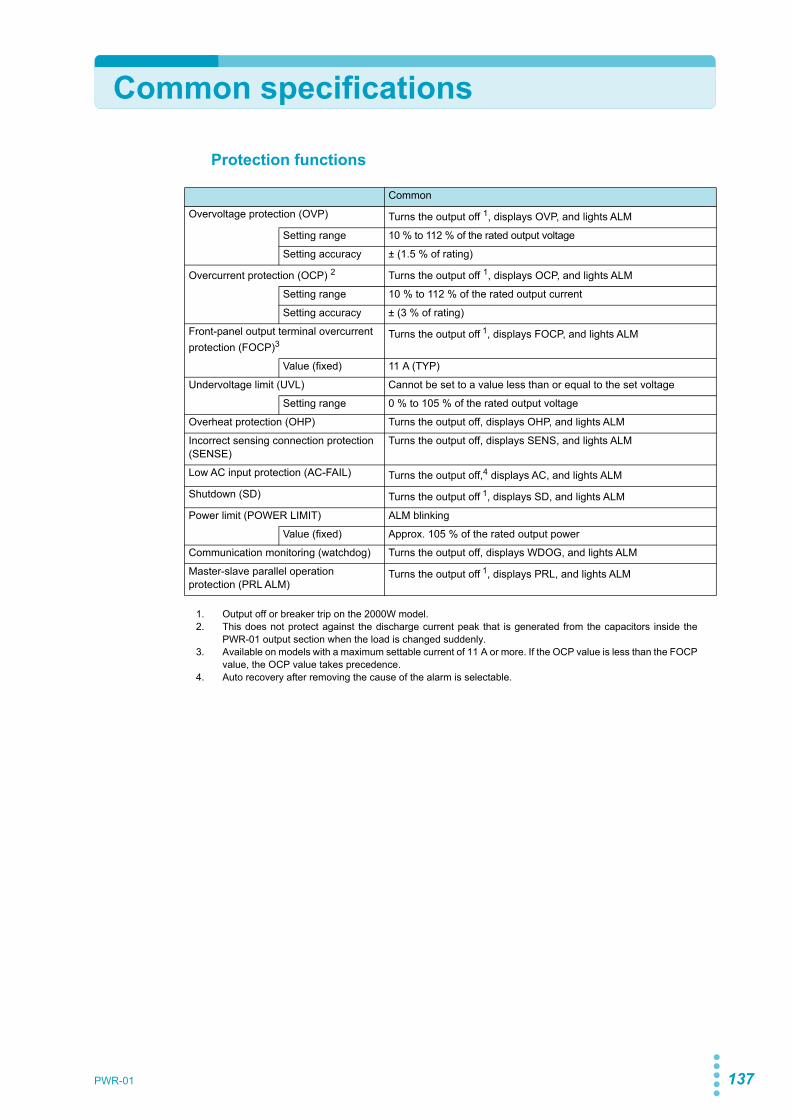
PWR-01 137
Common specifications
Protection functions
Common
Overvoltage protection (OVP) Turns the output off 1, displays OVP, and lights ALM
Setting range 10 % to 112 % of the rated output voltage
Setting accuracy ± (1.5 % of rating)
Overcurrent protection (OCP) 2 Turns the output off 1, displays OCP, and lights ALM
Setting range 10 % to 112 % of the rated output current
Setting accuracy ± (3 % of rating)
Front-panel output terminal overcurrent protection (FOCP)3
Turns the output off 1, displays FOCP, and lights ALM
Value (fixed) 11 A (TYP)
Undervoltage limit (UVL) Cannot be set to a value less than or equal to the set voltage
Setting range 0 % to 105 % of the rated output voltage
Overheat protection (OHP) Turns the output off, displays OHP, and lights ALM
Incorrect sensing connection protection (SENSE)
Turns the output off, displays SENS, and lights ALM
Low AC input protection (AC-FAIL) Turns the output off,4 displays AC, and lights ALM
Shutdown (SD) Turns the output off 1, displays SD, and lights ALM
Power limit (POWER LIMIT) ALM blinking
Value (fixed) Approx. 105 % of the rated output power
Communication monitoring (watchdog) Turns the output off, displays WDOG, and lights ALM
Master-slave parallel operation protection (PRL ALM)
Turns the output off 1, displays PRL, and lights ALM
1. Output off or breaker trip on the 2000W model.2. This does not protect against the discharge current peak that is generated from the capacitors inside the
PWR-01 output section when the load is changed suddenly.3. Available on models with a maximum settable current of 11 A or more. If the OCP value is less than the FOCP
value, the OCP value takes precedence.4. Auto recovery after removing the cause of the alarm is selectable.

138 PWR-01
Specifications| Common specifications
Signal output and input
Control functions
Common
Monitorsignal output
Voltage monitor (VMON) Selectable monitor voltage range: 0 V to 5 V or 0 V to 10 V
Setting accuracy 2.5 % of f.s.1
Current monitor (IMON) Selectable monitor voltage range: 0 V to 5 V or 0 V to 10 V
Setting accuracy 2.5 % of f.s.1
Statussignal output2
OUTON STATUS On when output is on.
CV STATUS Turns on during CV operation
CC STATUS Turns on during CC operation
ALARM STATUS Turns on when an alarm has been activated
POWER ON STATUS Turns on when the power is turned on
Trigger signal Input (TRG IN) Logic selectable: LOW (0 V to 1.5 V), HIGH (3.5 V to 5 V)Input impedance: 10 kΩ (TYP)
Output (TRG OUT) Logic selectable: LOW (0 V to 0.6 V), HIGH (4.2 V to 5 V)Pulse width: 100 µs (TYP)
1. f.s. is the full scale at the selected range. It is 10 V for the 10 V range and 5 V for the 5 V range.2. Photocoupler open collector output;
maximum voltage 30 V, maximum current (sink) 8 mA; isolated from the output and control circuits;status commons are floating (withstand voltage of less than or equal to 60 V); and status signals are notmutually isolated.
Common
Externalcontrol
Output voltage control (VPGM)
0 % to 100 % of the rated output voltageSelectable control voltage range: 0 V to 5 V or 0 V to 10 V
Accuracy 5 % of rating
Output current control (IPGM)
0 % to 100 % of the rated output currentSelectable control voltage range: 0 V to 5 V or 0 V to 10 V
Accuracy 5 % of rating
Output on/ off controlOUTPUT ON/OFF CONT
Logic selectable:Output on when set to LOW (0 V to 0.5 V) or shorted; output off when set to HIGH (4.5 V or 5 V) or openOutput on when set to HIGH (4.5 V to 5 V) or open; output off when set to LOW (0 V or 0.5 V) or shorted
Output shutdown controlSHUT DOWN
Output on when set to LOW (0 V to 0.5 V) or shorted
Alarm clear controlALM CLR
Alarm cleared when set to LOW (0 V to 0.5 V) or shorted

PWR-01 139
Specifications| Common specifications
Other functions
400W model 800W model 1200W model 2000W model
Output-on/ off delay Setting range: 0.0 s, 0.5 s to 99.9 s1setting resolution: 0.1 s
Soft start and soft stop Setting range: 0.0 s, 0.5 s to 10.0 s1?setting resolution: 0.1 s
Overcurrent protection (OCP) activation delay
Setting range: 0.0 s to 2.0 s1?setting resolution: 0.1 s
Preset memory Up to three sets of the following settings can be saved: the set voltage, the set current, the set OVP, the set OCP, and the set UVL.
Key lock Locks the operation of all keys other than the OUTPUT key.
CONFIG shortcut Up to three CONFIG parameters can be registered to the SC1, SC2, and SC3 keys.
Sequence Number of programs: 1Number of steps: 64Repetition count: 1 to 99998, INFinityNumber of configurable interval loops: 16Number of interval loops: 2 to 99998Step time: 0.1 s to 100 h (common to step transition and ramp transition)
Synchronized Operation Synchronization of voltage and current settings, synchronization of the resumption of steps in a sequence program
Master-slave parallel operation2 Up to three units (same models) including the master unit
Up to two units (same models) including the master unit
Series operation3 Two units (the same model)
Multichannel (VMCB)
Connection between the master unit and PC
LAN, USB, RS232C
Connection with slave units
LAN
1. Factory default is 0.0 s.2. Current difference between the master and slaves is 5 % (TYP).3. H type is excluded.
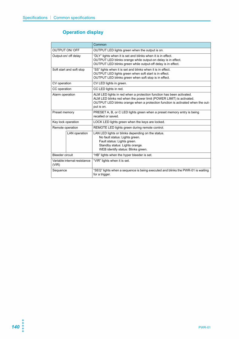
140 PWR-01
Specifications| Common specifications
Operation display
Common
OUTPUT ON/ OFF OUTPUT LED lights green when the output is on.
Output-on/ off delay “DLY” lights when it is set and blinks when it is in effect.OUTPUT LED blinks orange while output-on delay is in effect.OUTPUT LED blinks green while output-off delay is in effect.
Soft start and soft stop “SS” lights when it is set and blinks when it is in effect.OUTPUT LED lights green when soft start is in effect.OUTPUT LED blinks green when soft stop is in effect.
CV operation CV LED lights in green.
CC operation CC LED lights in red.
Alarm operation ALM LED lights in red when a protection function has been activated.ALM LED blinks red when the power limit (POWER LIMIT) is activated.OUTPUT LED blinks orange when a protection function is activated when the out-put is on.
Preset memory PRESET A, B, or C LED lights green when a preset memory entry is being recalled or saved.
Key lock operation LOCK LED lights green when the keys are locked.
Remote operation REMOTE LED lights green during remote control.
LAN operation LAN LED lights or blinks depending on the status.No fault status: Lights green.Fault status: Lights green.Standby status: Lights orange.WEB identify status: Blinks green.
Bleeder circuit “HB” lights when the hyper bleeder is set.
Variable internal resistance (VIR)
“VIR” lights when it is set.
Sequence “SEQ” lights when a sequence is being executed and blinks the PWR-01 is waiting for a trigger.

PWR-01 141
Specifications| Common specifications
Interface
Common
Common specifications
Software protocol IEEE Std 488.2-1992
Command language Complies with SCPI Specification 1999.0
RS232C Hardware Complies with the EIA232D specifications (excluding the connector)
RJ-45 connector (male)1
Baud rate: 1200, 2400, 4800, 9600, 19200, 38400, 57600, 115200 bps
Data length: 8 bits, Stop bits: 1 bit, Parity bit: None
No flow control
Program message terminator LF during reception, CR/LF during transmission
USB Hardware Complies with the USB 2.0 specifications; data rate: 480 Mbps (HighSpeed)
Socket B type
Program message terminator LF or EOM during reception, LF + EOM during transmission
Device class Complies with the USBTMC-USB488 device class specifications
LAN Hardware IEEE 802.3 100Base-TX/ 10Base-T EthernetComplies with LXI Specification2011 Ver.1.4Complies with LXI HiSLIP Extended Function Rev.1.01
IPv4, RJ-45 connector2
Communication protocol VXI-11, SCPI-RAW, HiSLIP
Program message terminator VXI-11, HiSLIP: LF or END during reception, LF + END during transmissionSCPI-RAW: LF during reception, LF during transmission.
1. The RD-8P/9P adapter cable is an option.2. Category 5; use a straight cable.

142 PWR-01
Specifications| Common specifications
General
400W model 800W model 1200W model 2000W model
Weight (main unit only) Approx. 3 kg (6.61 lb)
Approx. 5.5 kg (12.13 lb)
Approx. 7.5 kg (16.53 lb)
Approx. 13 kg (28.66 lb)
Dimensions See the outline drawing.
Environ-mental conditions
Operating environment Indoor use, overvoltage category II
Operating temperature 0 °C to +50 °C (32 °F to +122 °F)
Operating humidity 20 %rh to 85 %rh (no condensation)
Storage temperature -25 °C to +60 °C (-13 °F to 140 °F)
Storage humidity 90 %rh or less (no condensation)
Altitude Up to 2000 m
Cooling method Forced air cooling using fan
Grounding polarity Negative grounding or positive grounding possible
Isolation voltage L/ ML/ MH type: ±500 VmaxH type: ±800 Vmax
With-standing voltage
Across the primary circuit and chassis
No abnormalities when 1500 Vac is applied for 1 minute
Across the primary and secondary circuits
L/ ML/ MH type: No abnormalities when 1650 Vac is applied for 1 minuteH type: No abnormalities when 1900 Vac is applied for 1 minute
Across the secondary circuit and chassis
L/ ML/MH type: No abnormalities when 2300 Vdc is applied for 1 minuteH type: No abnormalities when 2640 Vdc is applied for 1 minute
Insulation resistance
Across the primary circuit and chassis
100 MΩ or more (70 % or less) at 500 Vdc
Across the primary and secondary circuits
L/ ML/ MH type: 100 MΩ or more (70 % or less) at 500 VdcH type: 100 MΩ or more (70 % or less) at 1000 Vdc
Across the secondary circuit and chassis
L/ ML/ MH type: 40 MΩ or more (70 % or less) at 500 VdcH type: 40 MΩ or more (70 % or less) at 1000 Vdc
Accessories See p.3.
Electromagnetic compatibility (EMC)1 2
Complies with the requirements of the following directive and standards.EMC Directive 2014/30/EUEN61326-1 (Class A3)
EN55011 (Class A.3, Group 14)EN61000-3-2EN61000-3-3
Applicable under the following conditionsThe maximum length of all cabling and wiring connected to the product must be less than 3 m.
Safety1 Complies with the requirements of the following directive and standards. Low Voltage Directive 2014/35/EU2
EN61010-1 (Class I5, Pollution Degree 26)
1. Does not apply to specially ordered or modified products.2. Limited to products that have a CE mark. Does not apply unless a core is attached to the J1 connector cable.3. This is a Class A instrument. This product is intended for use in an industrial environment. This product may
cause interference if used in residential areas. Such use must be avoided unless the user takes specialmeasures to reduce electromagnetic emissions to prevent interference to the reception of radio andtelevision broadcasts.
4. This is a Group 1 instrument. This product does not generate and/or use intentionally radio-frequencyenergy, in the form of electromagnetic radiation, inductive and/or capacitive coupling, for the treatment ofmaterial or inspection/analysis purpose.
5. This is a Class I instrument. Be sure to ground this product's protective conductor terminal. The safety ofthis product is guaranteed only when the product is properly grounded.
6. Pollution is addition of foreign matter (solid, liquid or gaseous) that may produce a reduction of dielectricstrength or surface resistivity. Pollution Degree 2 assumes that only non-conductive pollution will occurexcept for an occasional temporary conductivity caused by condensation.

AppendixA Factory Default SettingsB OptionsC Troubleshooting

144 PWR-01
A Factory Default Settings
You can initialize the settings to their factory default conditions.
1 While holding down LOCAL and PWR DSPL, turn the POWER switch on.
2 When the voltmeter on the front panel displays “INIT” appears, releaseLOCAL and PWR DSPL.
If you keep holding down the keys when “INIT” is displayed, the keys will be locked (theLOCK LED will light) (p.78).If the keys are locked (the LOCK LED is lit), you can hold down LOCAL and PWR DSPLagain to release the key lock.
The factory default settings are shown below.
Basic settingsBasic item DescriptionOutput voltage 0 VOutput current 105 % of the rated output currentOVP (overvoltage protection) 112 % of the rated output voltageOCP (overcurrent protection) 112 % of the rated output currentUVL (undervoltage limit) 0 VPreset memory values A, B, C Factory default settings
(Output voltage, output current, OVP, OCP, UVL)CONFIG shortcutSC1, SC2, SC3
No CONFIG parameter registration

PWR-01 145
Appendix| Factory Default Settings
CONFIG settingsParameter number Description Description
CF011 BLE Sets the bleeder circuit NORM (normal)
CF02 PRIO Output-on startup state CV (CV prioritized)CF03 VIR Internal resistance setting (VIR) OFF (internal resistance disabled)CF04 SS.C.R Soft start time (CC mode) 0.0 (soft start disabled)CF05 SS.C.F Soft stop time (CC mode) 0.0 (soft stop disabled)CF06 SS.V.R Soft start time (CV mode) 0.0 (soft start disabled)CF07 SS.V.F Soft stop time (CV mode) 0.0 (soft stop disabled)CF08 ON.D Output-on delay setting 0.0 (no delay)CF09 OFF.D Output-off delay setting 0.0 (no delay)CF10 E.CC CC control using an external voltage/ external resistance OFF (control not used)CF11 E.CV CV control using an external voltage/ external resistance OFF (control not used)CF12 E.RNG CV/ CC control range LO (0 V to 5 V)
CF131 M.RNG Voltage/ Current monitor output range LO (0 V to 5 V)
CF14 E.OUT External control for turning output on/ off OFF (external control not used)CF15 E.LOG External control logic for turning output on/off Turns on with LO (0 V to 0.5 V) or shortCF16 STS.C CC status signal polarity NEG (negative)CF17 STS.V CV status signal polarity NEG (negative)CF18 STS.O Output status signal polarity NEG (negative)CF19 STS.A Protection function/ alarm status signal polarity NEG (negative)
CF201 A.RCV Status when recovering from AC-FAIL protection SAFE (output not automatically turned on)
CF21 WDOG Communication monitoring (WATCHDOG) timer OFF (timer off)CF22 CC.LA Current setting limit ON (apply limit)CF23 CV.LA Voltage setting limit ON (apply limit)
CF241 OC.DL Detection time of OCP activation 0.0 s
CF251, 2 TRIP Breaker trip when the OVP/ OCP/ FOCP/ SD/ PRL ALM ON (trip)
CF30 SC1 CONFIG parameter shortcut registration (SC1) 00 (not registered)CF31 SC2 CONFIG parameter shortcut registration (SC2) 00 (not registered)CF32 SC3 CONFIG parameter shortcut registration (SC3) 00 (not registered)CF33 BEEP Buzzer on/ off ON (Buzzer on)
CF341 BRI Panel display brightness 7
CF35 AMTR Slave unit display during master-slave parallel operation OFF (not displayed)CF40 LAN LAN interface setting ON (used)CF41 USB USB interface setting ON (used)CF42 232 RS232C interface setting ON (used)CF43 TRAC SCPI communication error display OFF (not displayed)
CF441 PARA Master-slave parallel operation 1 (1 unit)
CF45 PON Output state at power-on SAFE (output off)CF60 BOOT LAN setting reset/ apply LCI (LAN interface setting reset)CF61 ADR IP address assignment method 110 (DHCP: On, AUTO IP: On, MANUAL IP: Off)CF66 SUB IP address subnet mask 16CF72 BAUD RS232C baud rate 19.2 (kbit/s)CF80 PROG Program’s user code display (execute) NONE (not written)CF83 TRG.I Trigger input signal polarity PTR (positive trigger)CF84 TRG.O Trigger output signal polarity PTR (positive trigger)
1. You can also specify this parameter when the PWR-01 is being used as a slave unit.2. Can be set only on the 2000W model.

146 PWR-01
B Options
The PWR-01 has the following options.For information about options, contact your Kikusui agent or distributor.
Rack mount option
Remove the handle and rubber feet before you mount the PWR-01 to a rack.For information on rack mounting, see the KRA3 or KRA150 operation manual.To support the main unit, attach an angle support to it that is appropriate for the rack.We recommend that you keep all pieces that you remove from the PWR-01. You will needthese pieces if you remove the PWR-01 from the rack mount adapter.When you re-attach the original rubber feet, use the pieces that you removed.
Name Model Note Applicable model
Rack mount adapter KRA3 For EIA inch racks 400W model800W model1200W model2000W model
KRA150 For JIS millimeter racks
KRA150
( 460)480
( 460)482
149
24.5
100
132.
5
57
260 260
37.7
5
KRA3
Unit: mm (inches)
1200W model example
To reinstall the handle that has been removed, use screw locking agent (e.g., 1401B by ThreeBond International, Inc.) to prevent screws from loosening.

PWR-01 147
Appendix| Options
Removing the handle and feet
1Pull up the handle cover (twolocations).
2Unfasten the two M4 flat headscrews, and remove theentire handle.
3Loosen the screws to removethe rubber feet (in fourlocations).
Power cordThis is the power cord that is used to connect the product to the AC line.
J1/ J2 connector plug kit OP01-PWR-01A plug kit for externally controlling thePWR through the J1/ J2 connector.
Adapter cable (RD-8P/9P)An adapter cable for connecting a D-sub 9-pinRS232C cable to the product.
Safety plugsPlugs for connecting to the front-panel output terminals. There are two types.
Rubber feet (four locations)
Screw (four locations)Four M3 screwsMaximum depth: 5 mm
Collar (four locations)
Bracket
Handle
CoverM4 flat head screw (M4x8)
AC5.5-3P3M-M4C-VCTF(not CE compliant)
For the 1200W model
AC5.5-1P3M-M6C-3S(CE compliant)
For the 2000W model
30 pin piecesHousing for the J1 connector and J2 connector, 1 piece each
TL41(screw connection type)Red and black, one set each
TL42(solder connection type)Red and black, one set each

148 PWR-01
Appendix| Options
Parallel operation cable (OP02-PWR-01)This cable is used when performing paralleloperations.For two units in parallel (one slave unit).
External control cable and connector set (OP03-PWR-01)A set of cables and connectors used forexternal control.
Terminal unit (TU01-PWR-01)A terminal unit for converting the J1 and J2 connectorsof this product to the J1 connector of the Kikusui PASand PWR Series Regulated DC Power Supplies.
Length: Approx. 400 mmCore: 1 piece
Slave side (White)
Master side (Blue)
Cables 20 pcs., length: approx. 500 mmHousing for the J1 connector and J2 connector, 1 piece eachCore 1 piece
Crimped on one end
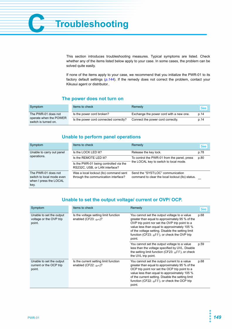
PWR-01 149
C Troubleshooting
This section introduces troubleshooting measures. Typical symptoms are listed. Checkwhether any of the items listed below apply to your case. In some cases, the problem can besolved quite easily.
If none of the items apply to your case, we recommend that you initialize the PWR-01 to itsfactory default settings (p.144). If the remedy does not correct the problem, contact yourKikusui agent or distributor..
The power does not turn on
Unable to perform panel operations
Unable to set the output voltage/ current or OVP/ OCP.
Symptom Items to check Remedy
The PWR-01 does not operate when the POWER switch is turned on.
Is the power cord broken? Exchange the power cord with a new one. p.14
Is the power cord connected correctly? Connect the power cord correctly. p.14
Symptom Items to check Remedy
Unable to carry out panel operations.
Is the LOCK LED lit? Release the key lock. p.78
Is the REMOTE LED lit? To control the PWR-01 from the panel, press the LOCAL key to switch to local mode.
p.80
Is the PWR-01 being controlled via the RS232C, USB, or LAN interface?
The PWR-01 does not switch to local mode even when I press the LOCAL key.
Was a local lockout (llo) command sent through the communication interface?
Send the “SYST:LOC” communication command to clear the local lockout (llo) status. —
Symptom Items to check Remedy
Unable to set the output voltage or the OVP trip point.
Is the voltage setting limit function enabled (CF23: ON)?
You cannot set the output voltage to a value greater than equal to approximately 95 % of the OVP trip point nor set the OVP trip point to a value less than equal to approximately 105 % of the voltage setting. Disable the setting limit function (CF23: OFF), or check the OVP trip point.
p.68
You cannot set the output voltage to a value less than the voltage specified by UVL. Disable the setting limit function (CF23: OFF), or check the UVL trip point.
p.59
Unable to set the output current or the OCP trip point.
Is the current setting limit function enabled (CF22: ON)?
You cannot set the output current to a value greater than equal to approximately 95 % of the OCP trip point nor set the OCP trip point to a value less than equal to approximately 105 % of the current setting. Disable the setting limit function (CF22: OFF), or check the OCP trip point.
p.68
See
See
See
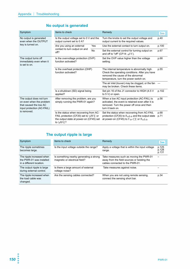
150 PWR-01
Appendix| Troubleshooting
No output is generated
The output ripple is large
Symptom Items to check Remedy
No output is generated even when the OUTPUT key is turned on.
Is the output voltage set to 0 V and the output current set to 0 A?
Turn the knobs to set the output voltage and output current to the required values.
p.40
Are you using an external contact to turn output on and off?
Yes Use the external contact to turn output on. p.100
No Set the external control for turning output on and off to "off" (CF14: OFF).
p.67
The output turns off immediately even when it is set to on.
Is the overvoltage protection (OVP) function activated?
Set the OVP value higher than the voltage setting.
p.68
Is the overheat protection (OHP) function activated?
The internal temperature is abnormally high. Check the operating conditions. After you have removed the cause of the abnormal temperature, turn the power switch on.
p.55
The air inlet (louver) may be clogged, or the fan may be broken. Check these items.
—
Is a shutdown (SD) signal being applied?
Set pin 16 of the J1 connector to HIGH (4.5 V to 5 V) or open.
p.102
The output does not turn on even when the problem that caused the low AC input protection (AC-FAIL) is removed.
After removing the problem, are you simply running the PWR-01 again?
When a low AC input protection (AC-FAIL) is activated, the event is retained even after it is removed. Turn the power off once and then turn it back on.
p.56
Is the status when recovering from AC-FAIL protection (CF20) set to SAFE or the output state at power-on (CF45) set to SAFE?
Set the status when recovering from AC-FAIL protection (CF20) to AUTO and the output state at power-on (CF45) to FORCE or AUTO.
p.68p.71
Symptom Items to check Remedy
The ripple sometimes becomes large.
Is the input voltage outside the range? Apply a voltage that is within the input voltage range.
p.125p.128p.131
The ripple increased when the PWR-01 was installed in a different location.
Is something nearby generating a strong magnetic or electrical field?
Take measures such as moving the PWR-01 away from the field sources or twisting the cables connected to the PWR-01.
–
The output ripple is large during external control.
Is there a large amount of external voltage noise?
Take measures against noise. –
The ripple increased when the load cable was changed.
Are the sensing cables connected? When you are not using remote sensing, connect the sensing short bar.
p.34
See
See

PWR-01 151
Appendix| Troubleshooting
The output is unstableSymptom Items to check Remedy
When the output is on, turning the VOLTAGE knob or CURRENT knob results in unstable output.
Is the operation mode switching from CV to CC or CC to CV?
Change the setting (output voltage or output current) that is limiting the output to a value greater than the present setting. If the setting is at maximum, you must use a power supply that has a larger output voltage or current.
p.49
The output voltage or output current fluctuates.
Are you using master-slave parallel operation?
Compared to independent operation, the performance degrades slightly during master-slave parallel operation.
–
Are the sensing cables or sensing short bar connected?
When you are not using remote sensing, connect the sensing short bar.
p.34
Are both the CV and CC LEDs turned on?
If the output is oscillating when you are using remote sensing, insert a capacitor across the load.
p.34
The circuit may be malfunctioning. Immediately stop using the PWR-01, and have it repaired.
–
Do the sensing cables or load cables have poor contact, or are the cables broken?
Turn the POWER switch off, and check the wiring.
p.14
Does the load current have peaks, or is it pulse shaped?
The peak values may be exceeding the set constant current. Increase the set constant current or increase the current capacity.
p.49
The output voltage is offset from the voltage that the PWR-01 was generating when it was turned on.
Has 30 minutes passed since the power was turned on?
Warm up the PWR-01 for at least 30 minutes. –
The output voltage does not decrease even when the output is turned off.
If the bleeder circuit (CF01) set to off? If the bleeder circuit is set to off (CF01: DIS), the voltage when the output is on remains. Set the bleeder circuit to on (CF01: NORM/ HYP).
p.64
The output voltage is offset from the voltage setting.
Is the internal resistance setting (CF03) set to a value other than off?
Set the internal resistance to off (CF03: OFF). p.65p.84
See

152 PWR-01
Appendix| Troubleshooting
The ALM LED lights when the OUTPUT key is turned on.
Unable to perform remote control
Unable to control functions properly
The fan speed is fast
Symptom Items to check Remedy
The ALM LED lights when the OUTPUT key is turned on.
Are the sensing cables or sensing short bar connected?
When you are not using remote sensing, connect the sensing short bar.
p.34
Are the polarities of the sensing cables connected in reverse?
The polarities of the sensing cables may be connected in reverse, or the ends of the cables may be shorted. Check them.
p.34
Are you using remote sensing with long load cables?
Keep the voltage drop in the load cables within the compensation voltage range.
p.34
Are you using external control with a loose control cable?
Connect the cable correctly. p.90
Is the external voltage excessive during external control?
Apply the correct voltage. p.96p.98
Is the internal temperature too high? The overheat protection function has been activated. Check the operating environment.
p.55p.137
The louver may be clogged, or the fan may be broken. Check these items. p.122
The ALM LED lights when the load is changed.
Is a large external voltage—such as that of a battery load—being applied?
The overvoltage protection function or the overcurrent protection function may have been activated. Check them.The PWR-01 may be overloaded. Check the load.
p.19p.52
Is the actual output voltage higher than the set voltage that is displayed on the panel?
Is a special load connected?
Symptom Items to check Remedy
Remote control through the communication interface cannot be performed.
Is the communication interface you want to use turned on in CONFIG settings?
Select the remote control communication interface (CF40/ CF41/ CF42).
p.70
When the LAN interface is in use, the IP address cannot be obtained from the DHCP server.
Is the LAN LED lit in orange or red? If it is lit in orange, the PWR-01 is waiting for a response from the DHCP server.If it turns red afterward, the PWR-01 may have timed out.Consult your network administrator.
p.73
Symptom Items to check Remedy
The bleeder circuit on/off function does not work.
Are you using master-slave parallel operation or series operation?
When using master-slave parallel operation orseries operation, set the bleeder circuit settings(CF01) of all connected units to the samevalue.
p.64
Symptom Items to check Remedy
The fan rotates faster than normal when the POWER switch is turned on.
Is the bleeder circuit set to hyper bleeder (CF01: HYP)?
If hyper bleeder (CF01: HYP) was specified the last time the POWER switch was turned off, the fan speed will be set to the fastest setting. If necessary, set the bleeder circuit (CF01).
p.64p.82
See
See
See
See
PWR-01 153
AAC-FAIL ................................................................... 56alarm occurrence ..................................................... 50alarm signal ............................................................. 51alarm, clearing ......................................................... 51
Bbleeder circuit .......................................................... 64breaker requirement ................................................ 16
CCC control setting .................................................... 66CC mode .................................................................. 47communication monitoring timer .............................. 68CONFIG shortcut registration .................................. 69constant-current mode ............................................. 47constant-current power supply ................................. 47constant-voltage mode ............................................ 47current monitoring, range ......................................... 66current setting limit ................................................... 68CV control setting .................................................... 66CV mode .................................................................. 47CV/CC control range ................................................ 66
Ffirmware version ........................................................ 2FOCP ....................................................................... 55
Iinstallation
breaker selection .......................................... 16IP address assignment
AUTO IP ....................................................... 73MANUAL IP .................................................. 73using DHCP server ....................................... 73
IP address display ................................................... 71IP address prefix ...................................................... 73
JJ1 connector pin arrangement ................................. 92J2 connector pin arrangement ................................. 93
Kkey lock function ...................................................... 78
LLAN interface ........................................................... 70LAN interface, applying settings .............................. 72LAN interface, resetting ........................................... 72
MMAC address display ............................................... 72MANUAL IP setting (IP address manual) ................ 73memory function ...................................................... 77multichannel (VMCB) ................................................. 3
address ........................................................ 74domain ......................................................... 74
OOCP ......................................................................... 53OCP activation, detection time ................................ 68OHP ......................................................................... 55output
delay ............................................................. 42output on and off, external control ........................... 67output on and off, external control logic ................... 67output-on startup state ............................................. 64OVP ......................................................................... 52
PPARALLEL ALM ...................................................... 57parallel operation ..................................................... 71POWER LIMIT ......................................................... 59power-on status ....................................................... 71product ID display .................................................... 74protection function
communication monitoring ........................... 56front-panel output terminal overcurrent
protection ................................................ 55incorrect sensing connection protection ....... 55low AC input protection ................................ 56overcurrent protection .................................. 53overheat protection ...................................... 55overvoltage protection .................................. 52power limit .................................................... 59protection during master-slave parallel operation
................................................................. 57shutdown ...................................................... 56undervoltage limit ......................................... 59
Rrack mount adapter ................................................ 146remote interface ....................................................... 70remote sensing ........................................................ 34RS232C interface .................................................... 70RS232C interface, baud rate ................................... 75
SSCPI communication error display .......................... 71SD ............................................................................ 56SENSE .................................................................... 55
Index
154 PWR-01
sequenceloop count ......................................................75remaining time ...............................................75trigger input ...................................................76trigger output .................................................76user code ......................................................75
setting limitcurrent setting limit ........................................59voltage setting limit ........................................58
setting limit, UVL ......................................................59setting limits ..............................................................41settings, reset ...........................................................64
Ttroubleshooting .......................................................149
UUSB interface ...........................................................70UVL ..........................................................................59
Vvariable internal resistance function .........................84vendor ID display ......................................................74version ........................................................................2VMCB (Virtual Multi Channel Bus)
channel ...................................................74, 75domain ..........................................................74
voltage monitoring, range .........................................66voltage setting limit ...................................................68
WWATCHDOG ............................................................56

KES4022 155
KIKUSUI ELECTRONICS CORP.
www.kikusui.co.jp/en
1-1-3 Higashiyamata, Tsuzuki-ku, Yokohama, 224-0023, JapanTel: +81-45-482-6353Fax: +81-45-482-6261
If you find any misplaced or missing pages in the manuals, they will be replaced. If the manual gets lost or soiled, a new copy can be provided for a fee. In either case, please contact your Kikusui agent or distributor. At that time, inform your agent or distributor of the “Part No.” written on the front cover of this manual.Every effort has been made to ensure the accuracy of this manual. However, if you have any questions or find any errors or omissions, please contact your Kikusui agent or distributor.After you have finished reading this manual, store it so that you can use it for reference at any time.
The newest version of the operation manual can be downloaded from Download service of Kikusui website.