Embed Size (px)
Citation preview
Arab J Sci Eng (2014) 39:1399–1408DOI 10.1007/s13369-013-0723-x
RESEARCH ARTICLE - MECHANICAL ENGINEERING
Feedforward, Hot and Cold Control System for Controlling PlasticInsulation Thickness in Manufacturing of Cable Products
Hisham Hussein
Received: 6 August 2011 / Accepted: 9 July 2013 / Published online: 12 September 2013© King Fahd University of Petroleum and Minerals 2013
Abstract This paper presents different control strategies forcontrolling cable insulation thickness for a plastic-on-wireextrusion process. Different control strategies are comparedlike cascade control, feedforward control. Finally a combinedcontrol strategy [dynamic feedforward and cascade (hot andcold control)] is proposed and its effectiveness is demon-strated.
Keywords Proportional-integral control · Insulationthickness · Cascade control · Feedforward control ·Combined control
1 Introduction
This work is related to the manufacturing of wire and cableproducts, more particularly, to an insulated wire having a pre-determined insulation thickness value which is well definedin the product specifications [1]. Control of a plastic coat-ing on-wire is a typical extrusion process control problem,where one of the prime measures of product quality is its
H. Hussein (B)Department of electrical engineering, Ha’il University,P.O. Box 2440 Hail, Hail Region, Saudi Arabiae-mail: [email protected]
required plastic insulation thickness. This work is related tothe methods of controlling the plastic insulation thickness ofthe insulated wire during steady-state operating conditions.
In a wire insulating line, major factors that determine theplastic insulation thickness of the insulated wire are extruder(screw) speed and wire take-up (line) speed [1]. Usually theoperator manually adjusts the required insulation thickness.In other words, the operator selects the appropriate line speedof the take-up drive unit and the screw speed of the extruder.In this case the operator usually adheres to the upper rangeof the plastic insulation thickness value, as such upper rangeprovides easier and more practical operating conditions, i.e.,there is a lesser possibility for the insulation thickness vari-ations to become less than the given lower range.
Thus, when the screw speed is increased or the take-upline speed is reduced, the insulation thickness of the layerextruded onto the wire increases. However, by following theaforementioned method of manually adjusting the requiredinsulation thickness, it has been observed that a large over-consumption of the expensive plastic material occurs, thatis why it is very important to propose different automaticcontrol systems for this technical process.
It is worth mentioning that an intensive work on the plas-tic extrusion line and its several parameters which deter-mine the quality of the insulated wire product is addressedin the literature [2–14]. However, to the best of my knowl-edge, a limited number of papers have been addressed to theissue of controlling the plastic insulation thickness parameter[15–18].
During the wire coating process [6], it is revealed that theextrudate viscosity is a key parameter in the control of phys-ical characteristics of the polymer coating. Based on Ref.[7], a comparison between the implemented techniques ofcomputerized control of a plastic extrusion plant over con-ventional techniques is given. Moore [8] addresses the new
123
1400 Arab J Sci Eng (2014) 39:1399–1408
controls adopted for the extrusion plant, especially for tem-perature and drive control. The design of a control softwareenvironment, namely the integrated design notation (IDN) ispresented in Ref. [9] and a cable extrusion process is targetedas a demonstrator application, where object orientation tech-nology is expected to facilitate the improvement of extrudercontrol in a distributed environment.
The idea proposed in Ref. [10] shows that the quality ofpolymer-on-wire extrusion process depends to a great extendon the correct choice of the operating conditions during thecooling process of the insulated wire. An automatic controlsystem is proposed which attempts to find the optimal coolingconditions for a certain cable product type during the startupof the extrusion line. A novel genetic algorithm strategyfor the determination of optimal input parameters of powercables production lines is presented in Ref. [11]; severalexamples of technical relevance are reported for the impor-tant case of high-voltage cables. A new proportional-integral-derivative (PID) fuzzy scheme is proposed in Ref. [12] tocontrol the temperature of a plastic extrusion barrel. Theobtained results show that the PID fuzzy control algorithmgives better performance criteria in terms of shorter rise timeand smaller overshoot than a conventional PID controller.
Adaptive neuro fuzzy inference system (ANFIS) con-troller design method for temperature control in plastic extru-sion system is presented in Ref. [13]. The obtained resultsshow that ANFIS controller gives better performance thanFuzzy logic and PID controller and significantly improves theperformance of the temperature control in plastic extrusionsystem. An active recognition and adaptive control (ARAC)system for polymer extrusion production line is proposed inRef. [14]. It is shown that the objective of ARAC is to emu-late not only the control experience of human expert, butalso the strategies or thinking of the expert to be utilized inmonitoring and controlling the real-time operating systems.
A modified smith predictor was proposed for controllingoutput dimensions from a plastic-on-wire extrusion processusing gain scheduled proportional-integral (PI) control in asmith predictor control scheme [15]. The idea proposed inRef. [16] argues that new technologies including advancedcontrol algorithms and software methodologies are beingsubject to standardization. The control of insulation thicknesson electrical cables is reviewed to demonstrate how this stan-dardization is progressed as well as to illustrate the potentialfor creating more comprehensive range of standardized con-trol components. The compensatory fuzzy neural network inplastics thickness control system is proposed in Ref. [17];a comparison with a PI control is shown through the sim-ulation results. A new hardware and software design of aplastic extruder control system based on digital communi-cation technique is presented in Ref. [18]. The new systemis constituted of an integrated control mode with personalcomputer (PC) and programmable logic controller (PLC).
In the next section, we will describe the mathematicalmodel of plastic insulation thickness measurement on a cableextrusion process which was used to provide the basis forfurther analysis and simulation.
2 Mathematical Model
2.1 Description of the Process
The extrusion process takes pellets of polymer. The pel-lets are plasticized, heated and mixed using a screw insidea heated barrel. The heated mix is extruded through a dieand then the extruded polymer covers a non-insulated wire.After the extrusion, the insulated wire is conveyed by a take-up drive unit to a cooling trough to allow handling of theinsulated wire without deformation.
From the production point of view, the required insulationthickness has to be kept close to the minimum as possible,therefore it is important to continuously monitor and con-trol any variations in the insulation thickness of the wire atthe required upper and lower range which is defined in theproduct specifications [1,15,16].
2.2 Developing Mathematical Model
The analysis of the extrusion process shows that the plasticinsulation thickness is determined by the following factors[1–3]:
The temperature of the extruder operating zones and thetemperature of the extruder die.
– The die geometry.– The screw speed.– The physical and rheological characteristics of the poly-
mer coating.– The line speed of the take-up drive unit.
δ = f {Sl , Ss, TM , μ(t), E} (1)
where δ is the insulation thickness of a cable, Sl is the linespeed of the take-up drive, Ss is the screw speed, TM rep-resents a function which describes the temperature of theextruder operating zones and the temperature of the extruderdie, μ(t) represents a function which describes the techni-cal properties of the extruder die and its geometry, and Eis a constant which depends on the physical and rheologicalcharacteristics of the polymer coating.
It is well known that some of the elements in (1) affect theextrudate flow rate
Q = f {Ss, TM, μ(t), E} (2)
Taking into consideration (2) for controlling the plastic insu-lation thickness, it is possible to write
123
Arab J Sci Eng (2014) 39:1399–1408 1401
δ = f {Q, Sl} (3)
The previous relationships can be more exactly representedby taking into account the mass balance equation duringsteady-state operating conditions [1–5,15]. It is possible thento present the next equation
Q =(
π D2
4− πd2
4
)Sl (4)
where D is the extruded outer diameter, d is the input wirediameter.
Plastic insulation thickness can be represented as
δ = D − d
2
Consequently D = d + 2δ, then Eq. (4) can be rearranged togive the following equation
Q = π Sl[δ d + δ2] (5)
To solve for δ, the quadratic equation is applied
δ =√
(π Sld)2 + 4π Sl Q − π Sld
2π Sl(6)
Equation (6) can be significantly simplified if δ << d
δ = Q
πd Sl(7)
In the next section, we will present an overview of differentcontrol strategies with the objective of developing effectiveautomatic control systems for the sake of stabilizing the plas-tic insulation thickness in manufacturing of cable products.
3 Proposed Control Systems
3.1 Cascade Control System
It is necessary to continuously measure the wire insulationthickness. The required insulation thickness can be controlled
by adjusting the line speed of the wire and/or the screw speed,so the wire insulation thickness controller output may be usedto trim either the line speed or the screw speed according tothe practical constraints of each individual extrusion line.
Usually the measured insulation thickness is comparedwith a reference value and the resulted error signal is evalu-ated by a controller to adjust the line speed or the screw speeduntil the reference value has been reached. For many wireinsulation thickness control systems, the insulation thicknesssensor is positioned before the cooling trough (the so calledthe ’hot sensor’). Although this sensor offers faster measure-ment rate, it cannot be used as an accurate measure of the finalwire insulation thickness. This is due to the variable subse-quent shrinkage of the covered polymer as the insulated wirepasses through the cooling trough.
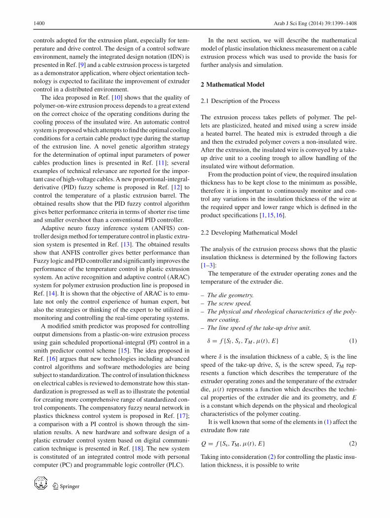
To improve the control performance of the proposed sys-tems, another sensor is positioned right after the coolingtrough (which is called the ’cold sensor’), at that point wherethe insulated wire is cooled down [15,16]. The block dia-gram with cold insulation thickness sensor is shown in Fig. 1below and the block diagram with cold and hot insulationthickness sensors is shown in Fig. 2.
In general, It is required that the insulation thickness mea-sured at the far sensor is controlled with minimum error, sothis loop is configured as a PI controller. Obviously, the maindisadvantage of this control system is the big transport delaybetween the extruder die and insulation thickness measure-ment; this could result in a slow control with reduced mater-ial savings, which is completely unacceptable in a controlledproduction environment [18].
To achieve the required insulation thickness and to pro-vide a fast and accurate control, it is possible to implementa cascade control with three feedback loops rather than acascade control with two feedback loops. This is achievedby monitoring the insulation thickness from the two sensorswhich are positioned before the extruder die and after thecooling trough. The output of the primary loop, in which itsprocess variable is the insulation thickness measured by the
Fig. 1 The block diagram withcold insulation thickness control
123
1402 Arab J Sci Eng (2014) 39:1399–1408
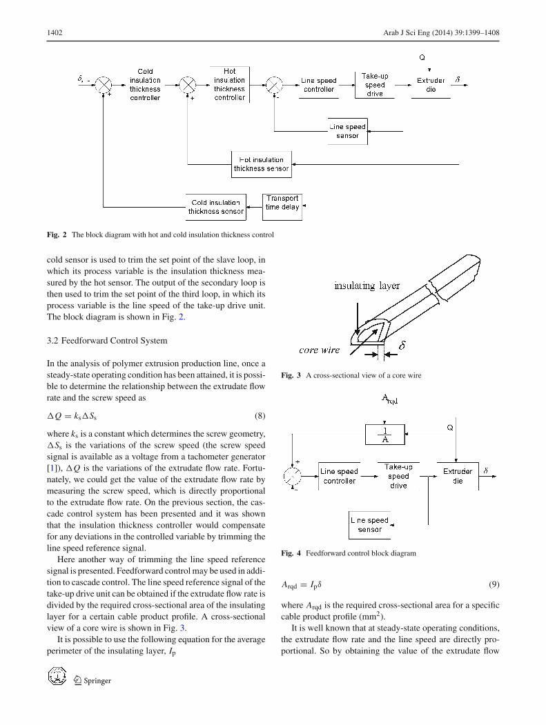
Fig. 2 The block diagram with hot and cold insulation thickness control
cold sensor is used to trim the set point of the slave loop, inwhich its process variable is the insulation thickness mea-sured by the hot sensor. The output of the secondary loop isthen used to trim the set point of the third loop, in which itsprocess variable is the line speed of the take-up drive unit.The block diagram is shown in Fig. 2.
3.2 Feedforward Control System
In the analysis of polymer extrusion production line, once asteady-state operating condition has been attained, it is possi-ble to determine the relationship between the extrudate flowrate and the screw speed as
�Q = ks�Ss (8)
where ks is a constant which determines the screw geometry,�Ss is the variations of the screw speed (the screw speedsignal is available as a voltage from a tachometer generator[1]), �Q is the variations of the extrudate flow rate. Fortu-nately, we could get the value of the extrudate flow rate bymeasuring the screw speed, which is directly proportionalto the extrudate flow rate. On the previous section, the cas-cade control system has been presented and it was shownthat the insulation thickness controller would compensatefor any deviations in the controlled variable by trimming theline speed reference signal.
Here another way of trimming the line speed referencesignal is presented. Feedforward control may be used in addi-tion to cascade control. The line speed reference signal of thetake-up drive unit can be obtained if the extrudate flow rate isdivided by the required cross-sectional area of the insulatinglayer for a certain cable product profile. A cross-sectionalview of a core wire is shown in Fig. 3.
It is possible to use the following equation for the averageperimeter of the insulating layer, Ip
Fig. 3 A cross-sectional view of a core wire
Fig. 4 Feedforward control block diagram
Arqd = Ipδ (9)
where Arqd is the required cross-sectional area for a specificcable product profile (mm2).
It is well known that at steady-state operating conditions,the extrudate flow rate and the line speed are directly pro-portional. So by obtaining the value of the extrudate flow
123
Arab J Sci Eng (2014) 39:1399–1408 1403
rate, Eq. (8), and relating on Eq. (9), and also taking intoconsideration the mass balance equation, we have
Q = Arqd Sl (10)
At a fixed Q, it is apparent that to provide the required cross-sectional area of the insulating layer, and consequently theplastic insulation thickness, it is necessary to strictly deter-mine the line speed reference signal. If the extrudate flowrate will be changed for some reasons, subsequently the linespeed should be changed. On the other side, if it is requiredto stabilize the cross-sectional area of the insulating layer at
a certain value, then from Eq. (10) the required line speedreference signal of the take-up drive unit is
Sl.req. = Q1
Arqd(11)
where the gain (1/Arqd) would be different for differentextruded cable profiles. From Eq. (11), it is clear that tostabilize the plastic insulation thickness at the requiredvalue, it is necessary to provide the line speed refer-ence signal. The feedforward block diagram is shown inFig. 4.
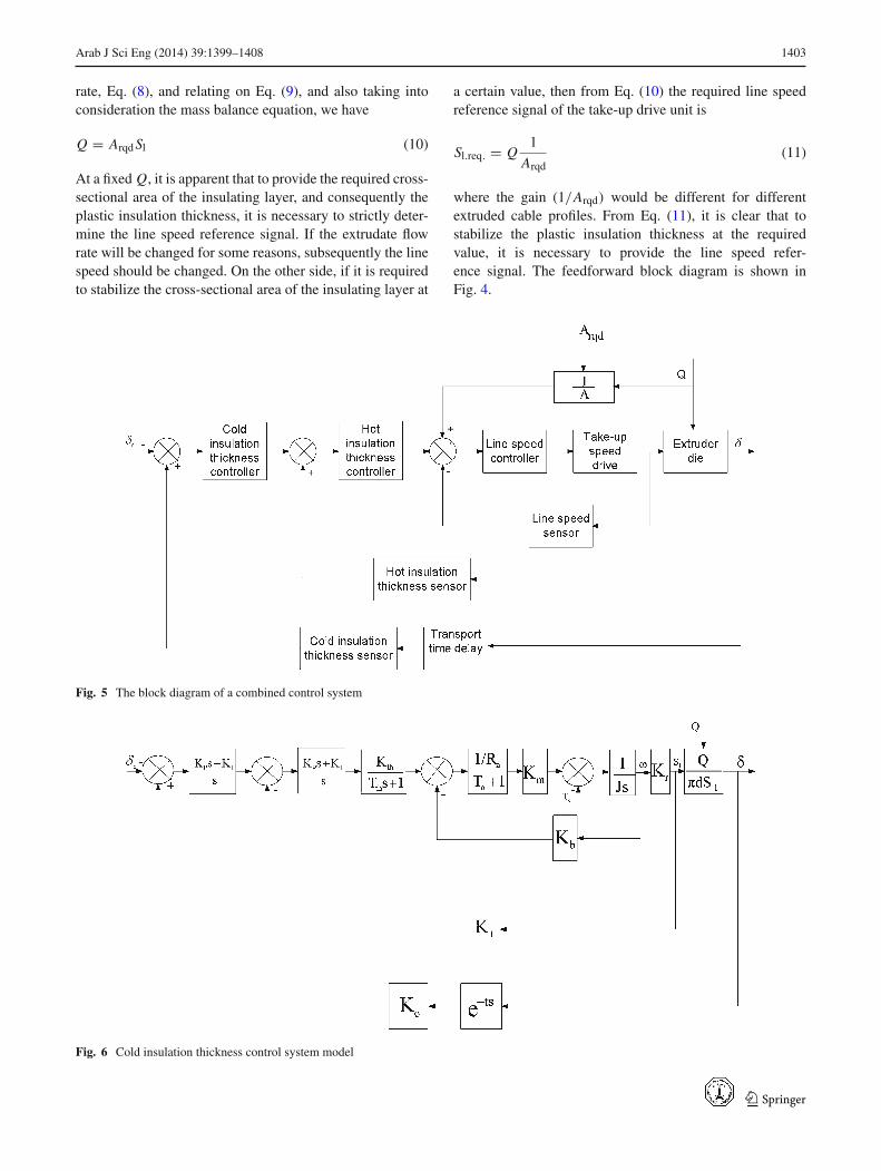
Fig. 5 The block diagram of a combined control system
Fig. 6 Cold insulation thickness control system model
123
1404 Arab J Sci Eng (2014) 39:1399–1408
3.3 Combined Control System
Feedforward control strategy can provide a more rapidresponse to known disturbances. From experience, the known
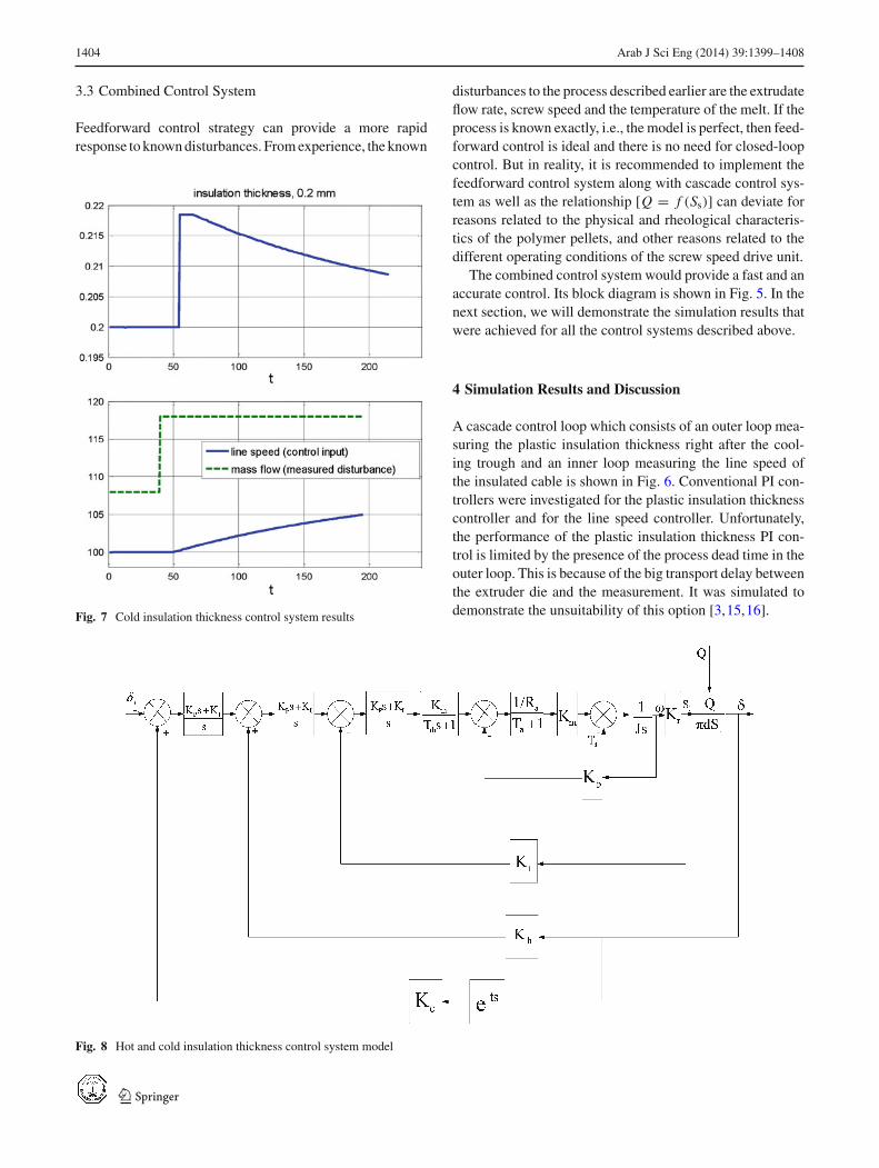
Fig. 7 Cold insulation thickness control system results
disturbances to the process described earlier are the extrudateflow rate, screw speed and the temperature of the melt. If theprocess is known exactly, i.e., the model is perfect, then feed-forward control is ideal and there is no need for closed-loopcontrol. But in reality, it is recommended to implement thefeedforward control system along with cascade control sys-tem as well as the relationship [Q = f (Ss)] can deviate forreasons related to the physical and rheological characteris-tics of the polymer pellets, and other reasons related to thedifferent operating conditions of the screw speed drive unit.
The combined control system would provide a fast and anaccurate control. Its block diagram is shown in Fig. 5. In thenext section, we will demonstrate the simulation results thatwere achieved for all the control systems described above.
4 Simulation Results and Discussion
A cascade control loop which consists of an outer loop mea-suring the plastic insulation thickness right after the cool-ing trough and an inner loop measuring the line speed ofthe insulated cable is shown in Fig. 6. Conventional PI con-trollers were investigated for the plastic insulation thicknesscontroller and for the line speed controller. Unfortunately,the performance of the plastic insulation thickness PI con-trol is limited by the presence of the process dead time in theouter loop. This is because of the big transport delay betweenthe extruder die and the measurement. It was simulated todemonstrate the unsuitability of this option [3,15,16].
Fig. 8 Hot and cold insulation thickness control system model
123
Arab J Sci Eng (2014) 39:1399–1408 1405
We used a range of proportional (P) and integral (I) gainsin the simulation and showed that the system would be unsta-ble with high gains of P and I. The system was stable only with
Fig. 9 Hot and cold insulation thickness control simulation results
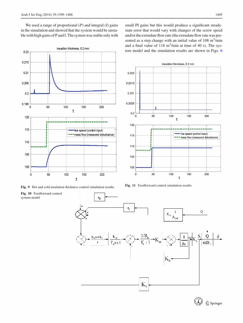
small PI gains but this would produce a significant steady-state error that would vary with changes of the screw speedand/or the extrudate flow rate (the extrudate flow rate was pre-sented as a step change with an initial value of 108 m3/minand a final value of 118 m3/min at time of 40 s). The sys-tem model and the simulation results are shown in Figs. 6
Fig. 11 Feedforward control simulation results
Fig. 10 Feedforward controlsystem model
123
1406 Arab J Sci Eng (2014) 39:1399–1408
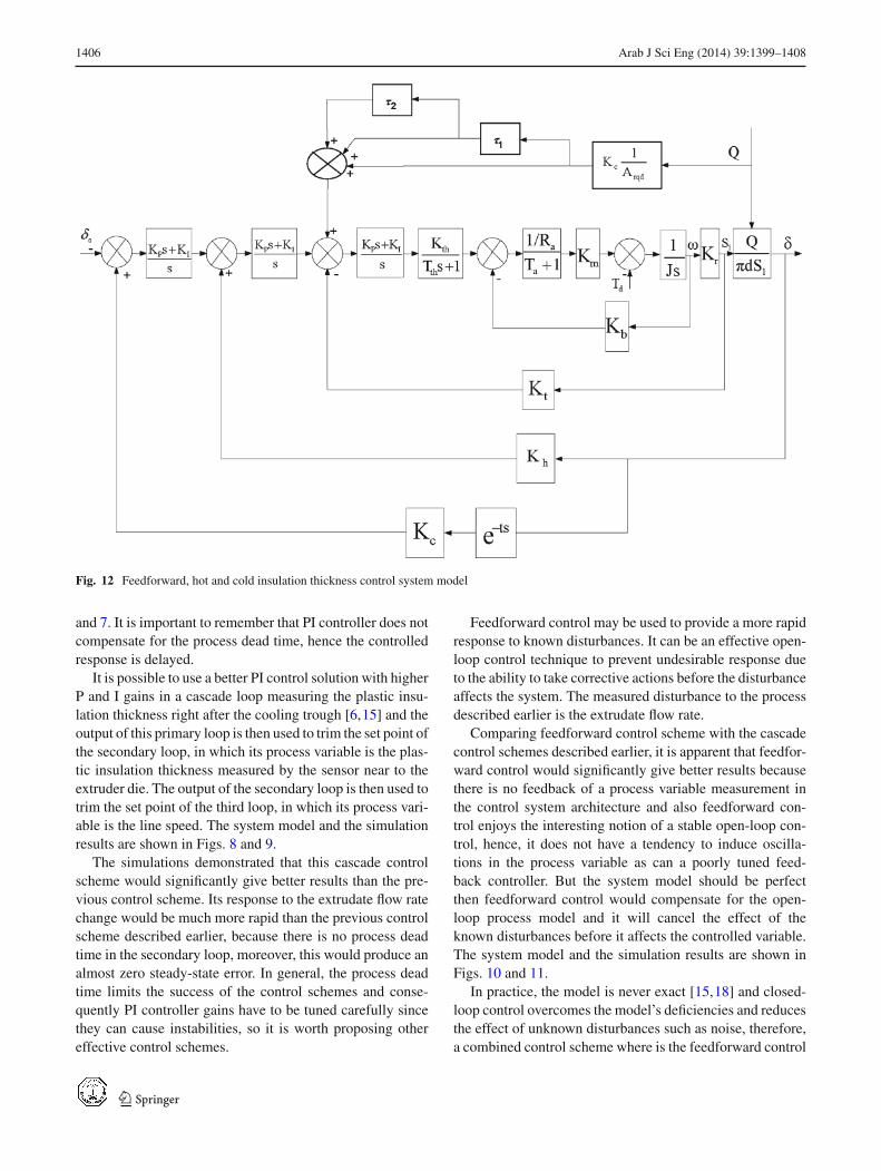
Fig. 12 Feedforward, hot and cold insulation thickness control system model
and 7. It is important to remember that PI controller does notcompensate for the process dead time, hence the controlledresponse is delayed.
It is possible to use a better PI control solution with higherP and I gains in a cascade loop measuring the plastic insu-lation thickness right after the cooling trough [6,15] and theoutput of this primary loop is then used to trim the set point ofthe secondary loop, in which its process variable is the plas-tic insulation thickness measured by the sensor near to theextruder die. The output of the secondary loop is then used totrim the set point of the third loop, in which its process vari-able is the line speed. The system model and the simulationresults are shown in Figs. 8 and 9.
The simulations demonstrated that this cascade controlscheme would significantly give better results than the pre-vious control scheme. Its response to the extrudate flow ratechange would be much more rapid than the previous controlscheme described earlier, because there is no process deadtime in the secondary loop, moreover, this would produce analmost zero steady-state error. In general, the process deadtime limits the success of the control schemes and conse-quently PI controller gains have to be tuned carefully sincethey can cause instabilities, so it is worth proposing othereffective control schemes.
Feedforward control may be used to provide a more rapidresponse to known disturbances. It can be an effective open-loop control technique to prevent undesirable response dueto the ability to take corrective actions before the disturbanceaffects the system. The measured disturbance to the processdescribed earlier is the extrudate flow rate.
Comparing feedforward control scheme with the cascadecontrol schemes described earlier, it is apparent that feedfor-ward control would significantly give better results becausethere is no feedback of a process variable measurement inthe control system architecture and also feedforward con-trol enjoys the interesting notion of a stable open-loop con-trol, hence, it does not have a tendency to induce oscilla-tions in the process variable as can a poorly tuned feed-back controller. But the system model should be perfectthen feedforward control would compensate for the open-loop process model and it will cancel the effect of theknown disturbances before it affects the controlled variable.The system model and the simulation results are shown inFigs. 10 and 11.
In practice, the model is never exact [15,18] and closed-loop control overcomes the model’s deficiencies and reducesthe effect of unknown disturbances such as noise, therefore,a combined control scheme where is the feedforward control
123
Arab J Sci Eng (2014) 39:1399–1408 1407
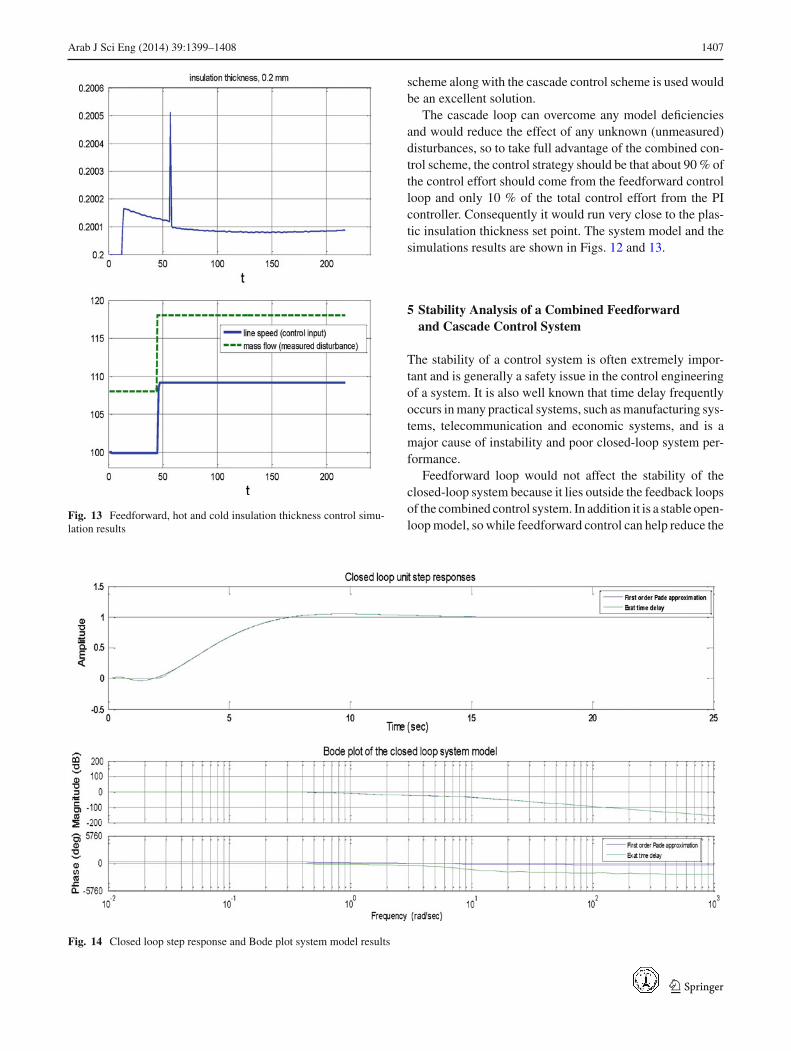
Fig. 13 Feedforward, hot and cold insulation thickness control simu-lation results
scheme along with the cascade control scheme is used wouldbe an excellent solution.
The cascade loop can overcome any model deficienciesand would reduce the effect of any unknown (unmeasured)disturbances, so to take full advantage of the combined con-trol scheme, the control strategy should be that about 90 % ofthe control effort should come from the feedforward controlloop and only 10 % of the total control effort from the PIcontroller. Consequently it would run very close to the plas-tic insulation thickness set point. The system model and thesimulations results are shown in Figs. 12 and 13.
5 Stability Analysis of a Combined Feedforwardand Cascade Control System
The stability of a control system is often extremely impor-tant and is generally a safety issue in the control engineeringof a system. It is also well known that time delay frequentlyoccurs in many practical systems, such as manufacturing sys-tems, telecommunication and economic systems, and is amajor cause of instability and poor closed-loop system per-formance.
Feedforward loop would not affect the stability of theclosed-loop system because it lies outside the feedback loopsof the combined control system. In addition it is a stable open-loop model, so while feedforward control can help reduce the
Fig. 14 Closed loop step response and Bode plot system model results
123
1408 Arab J Sci Eng (2014) 39:1399–1408
effect of measured disturbances on the controlled variable,cascade control is good for reference tracking.
To analyze the performance and stability of the closed-loop system model, a linear analysis of the closed-loop sys-tem model is shown in Fig. 14.
The main issue here is to show the effect of time delayon the performance and stability of the closed-loop controlsystem, for that reason, the time delay in the outer feedbackloop of the combined control system was replaced by itsPade approximation of a first-order transfer function and wascompared with the exact time delay representation during thesimulation tests.
By examining the phase of the Bode response we can seethe roll-off effect resulting from the exact representation ofthe delay. From Fig. 14, it is shown that the closed-loop unitstep responses for the control system with exact time delayrepresentation and with its Pade approximation are stable andthey match closely except for the non-minimum phase effectwhich is introduced by the Pade approximation.
6 Conclusion
From the simulations of the plastic insulation thickness con-trol problem, it was obvious that cascade (hot and cold) con-trol significantly gave better results in terms of minimiz-ing thickness deviations for the disturbance applied than acascade (cold) control. Feedforward control, gave the bestresults but again the model describing the process should beperfect.
A combined control strategy where additional benefits canbe achieved by combining the best features of cascade andfeedforward control is proposed. A Combined control systemwould compensate for any deficiencies in the process model;in addition, it would reduce the effect of unmeasured dis-turbances. The proposed approach can be extended to otherproduction lines such as, rolling mill lines, rubber productionlines, and many other processes.
Acknowledgments I would like to thank all my colleagues who havegiven me the support to finish this work. I would also like to thank thereviewers for their helpful comments and suggestions.
References
1. Sikora, H.: Control system for controlling the outer diameter ofa strand of plastic material, in particular of a cable. United statespatent Number: 5169649, Sikora Industieelektronik GmbH, Bre-men, Germany (1992)
2. Costin, M.H.; Taylor, P.A.; Wright, J.D.: A critical review ofdynamic modeling and control of plasticating Extruders. PolymerEng. Sci. 22(7), 393–400 (1982a)
3. Previdi, F.; Savaresi, S.; Panarotto, A.: Design of a feedback controlsystem for real-time control of flow in a single-screw extruder. Con-trol Eng Practice. 14(9), 1111–1121 (2006)
4. Costin, M.H.; Taylor, P.A.; Wright, J.D.: On the Dynamics andcontrol of a plasticating extruder. Polymer Eng. Sci. 22(17), 1095–1106 (1982)
5. Brian, T.; John, W.: Extrusion process control part 1: identificationand open-loop control. In: Proceedings of the American ControlConference. Albuquerque, New Mexico (1997)
6. Wagner, M.G.; Montague, G.A.: Modeling and control of a wirecoating process. In: Proceedings of the International Conferenceon Control. Newcastle upon Tyne University, UK (1994)
7. Harris, H. E.: Computerized control and management of a plasticsextrusion plant. IEEE Trans. Indus. Appl. IA 10(1), 106–111 (1974)
8. Moore, J.B.: Modern controls for plastics and rubber extrusion. In:IEEE Annual Conference, Electrical Engineering Problems in theRubber and Plastics Industries. NRM Corp., Columbiana, OH, pp.1–4 (1989)
9. Hernandez, R.; Fleming, D.N.; Bennett, P.J.; Hope, S.; Bass, S.;Baxter, J.M.: Process control systems integration using object ori-ented technology. In: Proceedings of Technology of Object- Ori-ented Languages and Systems. TOOLS 38 (2001)
10. Zinnatullin, R.R.; Kazakov, A.V.; Trufanova N.M.: Automatic con-trol system of extrusion of polymer cable insulation. Russian Elec-trical Eng. 82(11), 596–599 (2011)
11. Milani, G.; Milani, F.: Genetic algorithm for the optimization ofrubber insulated high voltage power cables production lines. Com-put. Chem. Eng. 32(12), 3198–3212 (2008)
12. Taur, J.S.; Tao, C.W.; Tsai, C.C.: Temperature control of a plasticextrusion barrel using PID fuzzy controllers. IEEE Int. Conf. Indus.Automat. Control Emerg. Technol, pp 370–375 (1995)
13. Ravi, S.; Balakrishnan, P.A.: Modeling and control of an ANFIStemperature controller for plastic extrusion process. In: IEEE Inter-national Conference on Communication Control and ComputingTechnologies, pp. 314–320 (2010)
14. Guo, P.; Ni, X.Z.; Zheng, J.: Polymer extrusion production controlusing active recognition and adaptive control system. IEEE SecondInt. Conf. Fuzzy Syst. 2, 779–784 (1993)
15. Smith, L.: Modified Smith predictor for extruded diameter control.Comput. Control Eng. J. SEEC Worthing, 32, 57–62 (1999)
16. Smith, L.: Applied control techniques—the drive toward standard-ization and components. IEE Colloquium on Advances in ControlTechnology, pp. 1–4. London, UK (1999)
17. Hong, Y.M.; Hong, Q.S.; Heng, J.: The application of compen-satory fuzzy neural network in plastics thickness control system.Control, Automat. Robotics Vision Conf. 3, 2155–2159 (2004)
18. Zhao, J.; Xiaofeng, W.: Application of digital communicationtechniques to plastic extrusion process. In: The Ninth Interna-tional Conference on Electronic Measurement and Instruments,pp. 2-34–2-37(2009)
123


![The Impact of Optimum Insulation Thickness of External ...Calculation of optimum insulation thickness of external walls of housing by using Life-Cycle Cost was discussed by Refs [11]-[33]](https://img.pdfslide.us/doc/110x75/6048989c14ef4171d913534c/the-impact-of-optimum-insulation-thickness-of-external-calculation-of-optimum.jpg)