Embed Size (px)
Citation preview
XA0055540
Feedback from Practical Experience with Large sodium Fire AccidentsV.P. Luster, K.F. Freudenstein (Siemens AG KWU)
ABSTRACT
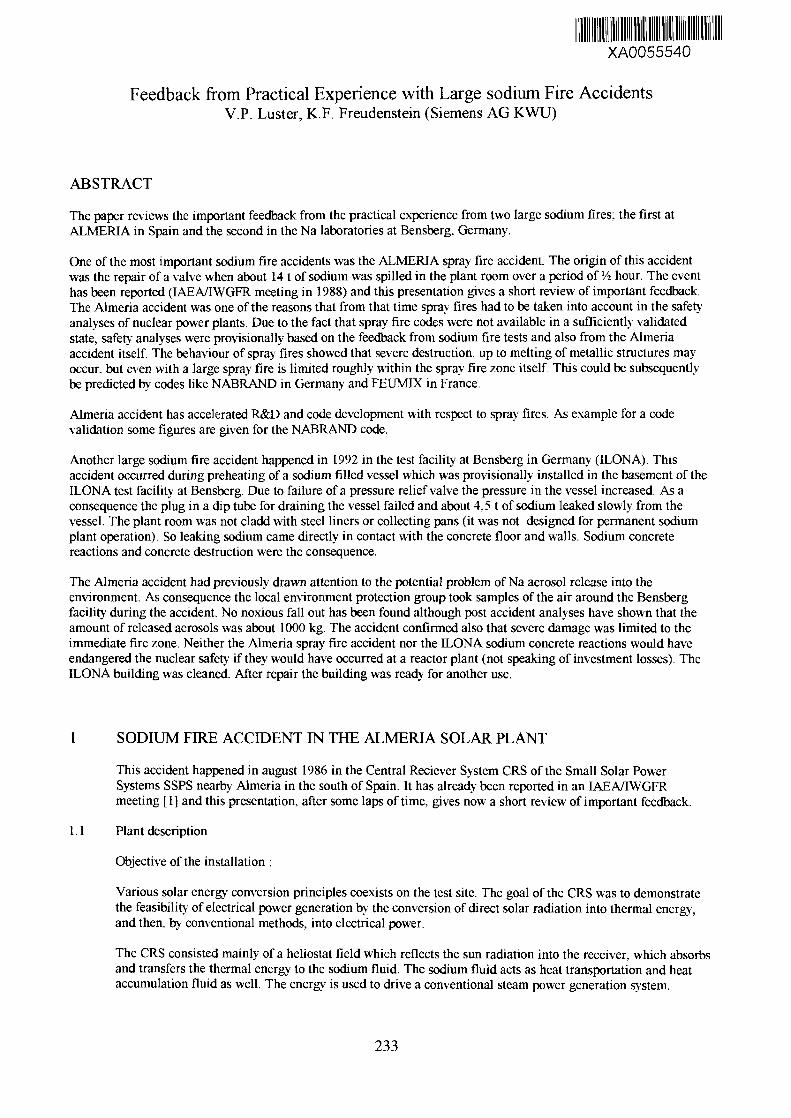
The paper reviews the important feedback from the practical experience from two large sodium fires; the first atALMERIA in Spain and the second in the Na laboratories at Bensberg, Germany.
One of the most important sodium fire accidents was the ALMERIA spray fire accident. The origin of this accidentwas the repair of a valve when about 14 t of sodium was spilled in the plant room over a period of lA hour. The eventhas been reported (IAEA/IWGFR meeting in 1988) and this presentation gives a short review of important feedback.The Almeria accident was one of the reasons that from that time spray fires had to be taken into account in the safety-analyses of nuclear power plants. Due to the fact that spray fire codes were not available in a sufficiently validatedstate, safety analyses were provisionally based on the feedback from sodium fire tests and also from the Almeriaaccident itself. The behaviour of spray fires showed that severe destruction, up to melting of metallic structures mayoccur, but even with a large spray fire is limited roughly within the spray fire zone itself. This could be subsequentlybe predicted by codes like NABRAND in Germany and FEUMLX in France.
Almeria accident has accelerated R&D and code development with respect to spray fires. As example for a codevalidation some figures are given for the NABRAND code.
Another large sodium fire accident happened in 1992 in the test facility at Bensberg in Germany (ILONA). Thisaccident occurred during preheating of a sodium filled vessel which was provisionally installed in the basement of theILONA test facility at Bensberg. Due to failure of a pressure relief valve the pressure in the vessel increased. As aconsequence the plug in a dip tube for draining the vessel failed and about 4,5 t of sodium leaked slowly from thevessel. The plant room was not cladd with steel liners or collecting pans (it was not designed for permanent sodiumplant operation). So leaking sodium came directly in contact with the concrete floor and walls. Sodium concretereactions and concrete destruction were the consequence.
The Almeria accident had previously drawn attention to the potential problem of Na aerosol release into theenvironment. As consequence the local environment protection group took samples of the air around the Bensbergfacility during the accident. No noxious fall out has been found although post accident analyses have shown that theamount of released aerosols was about 1000 kg. The accident confirmed also that severe damage was limited to theimmediate fire zone. Neither the Almeria spray fire accident nor the ILONA sodium concrete reactions would haveendangered the nuclear safety if they would have occurred at a reactor plant (not speaking of investment losses). TheILONA building was cleaned. After repair the building was ready for another use.
1 SODIUM FIRE ACCIDENT IN THE ALMERIA SOLAR PLANT
This accident happened in august 1986 in the Central Reciever System CRS of the Small Solar PowerSystems SSPS nearby Almeria in the south of Spain. It has already been reported in an IAEA/IWGFRmeeting fl] and this presentation, after some laps of time, gives now a short review of important feedback.
1.1 Plant description
Objective of the installation :
Various solar energy conversion principles coexists on the test site. The goal of the CRS was to demonstratethe feasibility of electrical power generation by the conversion of direct solar radiation into thermal energy,and then, by conventional methods, into electrical power.
The CRS consisted mainly of a heliostat field which reflects the sun radiation into the receiver, which absorbsand transfers the thermal energy to the sodium fluid. The sodium fluid acts as heat transportation and heataccumulation fluid as well. The energy is used to drive a conventional steam power generation system.
233
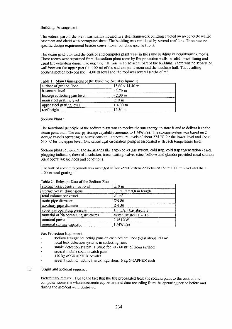
Building, Arrangement:
The sodium part of the plant was mainly housed in a steel framework building erected on an concrete walledbasement and cladd with corrugated sheet. The building was ventilated by several roof fans. There was nospecific design requirement besides conventional building specifications.
The steam generator and the control and computer plant were in the same building in neighbouring rooms.These rooms were separated from the sodium plant room by fire protection walls in solid -brick lining andusual fire-retarding doors. The machine hall was in an adjacent part of the building. There was no separationwall between the upper part ( + 4,00 m) of the sodium plant room and the machine hall. The resultingopening section between the + 4,00 m level and the roof was several tenths of m'.
Table 1 : Main Dimensions of the Building (See also figure 1)surface of ground floorbasement levelleakage collecting pan levelmain steel grating levelupper steel grating levelroof height
15,60 x 14,40 m- 3.70 m- 2,00 m± 0 m+ 4,00 m15,50 m
Sodium Plant:
The functional principle of the sodium plant was to receive the sun energy, to store it and to deliver it to thesteam generator. The energy storage capability amounts to 1 MWh(e). The storage system was based on 2storage vessels operating at nearly constant temperature levels of about 275 °C for the lower level and about530 °C for the upper level. One centrifugal circulation pump is associated with each temperature level.
Sodium plant equipment and auxiliaries like argon cover gas system, cold trap, cold trap regeneration vessel,plugging indicator, thermal insulation, trace heating, valves (steel bellows and glands) provided usual sodiumplant operating methods and conditions.
The bulk of sodium pipework was arranged in horizontal extension between the ± 0,00 m level and the +4,00 m steel grating.
Table 2 : Relevant Data of the Sodium Plant:storage vessel centre line levelstorage vessel dimensionstotal volume per vesselmain pipe diameterauxiliary pipe diametercover gas operating pressurematerial of Na containing structuresnominal powernominal storage capacity
± 0 m3,3 m 0 x 9,8 m length70 m3
DN80DN501.5 ...8,5 bar absoluteaustenitic steel 1.49482 464 kW1 MWh(e)
Fire Protection Equipment:sodium leakage collecting pans on each bottom floor (total about 300 nrlocal leak detection systems in collecting panssmoke detection system (1 probe for 30 - 60 m2 of room surface)several mobile sodium catch pans470 kg of GRAPHEX powderseveral tenth of mobile fire extinguishers, 6 kg GRAPHEX each
1.2 Origin and accident sequence
Preliminary remark : Due to the fact that the fire propagated from the sodium plant to the control andcomputer rooms the whole electronic equipment and data recording from the operating period before andduring the accident were destroyed.
234
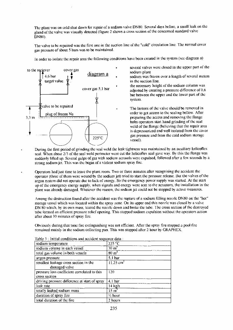
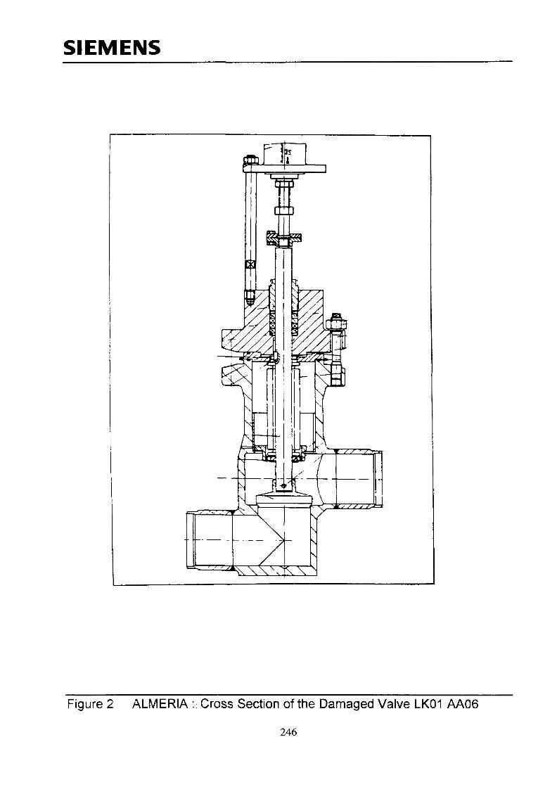
The plant was on cold shut down for repair of a sodium valve DN80. Several days before, a small leak on thegland of the valve was visually detected (figure 2 shows a cross section of the concerned standard valveDN80).
The valve to be repaired was the first one in the suction line of the "cold" circulation line. The normal covergas pressure of about 5 bars was to be maintained.
In order to isolate the repair area the following conditions have been created in the system (see diagram a)
to the raciever
I 4,6 bar
3.3 m
cover gas
target value ^7
L \
diagram a
cover gas 5,1 bar
S7A
valve to be repaired
plug of frozen Na
several valves were closed in the upper part of thesodium plantsodium was frozen over a length of several metersin the suction line.the necessary height of the sodium column wasadjusted by creating a pressure difference of 0,6bar between the upper and the lower part of thesystem.
The lantern of the valve should be removed inorder to get access to the sealing bellow. Afterpreparing the access and removing the flangebolts operators start hand grinding of the sealweld of the flange (believing that the repair areais depressurized and well isolated from the covergas pressure and from the cold sodium storagevessel).
During the first period of grinding the seal weld the leak tightness was maintained by an auxiliary helicoflexseal. When about 2/3 of the seal weld perimeter were cut the helicoflex seal gave way. By this the flange wassuddenly lifted up. Several gulps of gas with sodium aerosols were expulsed, followed after a few: seconds by astrong sodium jet. This was the begin of a violent sodium spray fire.
Operators had just time to leave the plant room. Two or three minutes after recognising the accident theoperator (three of them were wound by the sodium jet) tried to start the pressure release. But the valves of theargon system did not operate due to lack of energy. So the emergency power supply was started. At the startup of the emergency energy supply, when signals and energy were sent to the actuators, the installation in theplant was already damaged. Whatever the reason, the sodium jet could not be stopped by active measures.
Among the destruction found after the accident was the rupture of a sodium filling nozzle DN80 on the "hot"storage vessel which was located w ithin the spray zone. On its upper end this nozzle was closed by a valveDN 80 which, by its own mass, teared the nozzle down and broke the tube. The cross section of the destroyedtube formed an efficient pressure relief opening. This stopped sodium expulsion without the operators actionafter about 30 minutes of spray fire.
Obviously during that time fire extinguishing was not efficient. After the spray fire stopped a pool fireremained mainly in the sodium collecting pan. This was stopped after 2 hour by GRAPHEX.
Table 3 : Initial conditions and accident sequence data :sodium temperaturesodium volume in each vesseltotal gas volume in both vesselsargon pressuresmallest leakage cross section in the
damaged valvepressure loss coefficient correlated to thiscross sectiondriving pressure difference at start of spray-leak ratetotallv leaked sodium massduration of spray firetotal duration of the fire
225 °C30 m3
80 m3
5,1 bar11,25 cm2
120
4.1 bar14kg/s15 mJ
'/i hour2 hours
235
1.3 Damage are and material behaviour under sodium fire loads
1.3.1 Spray direction
4,0 m
0,0 m
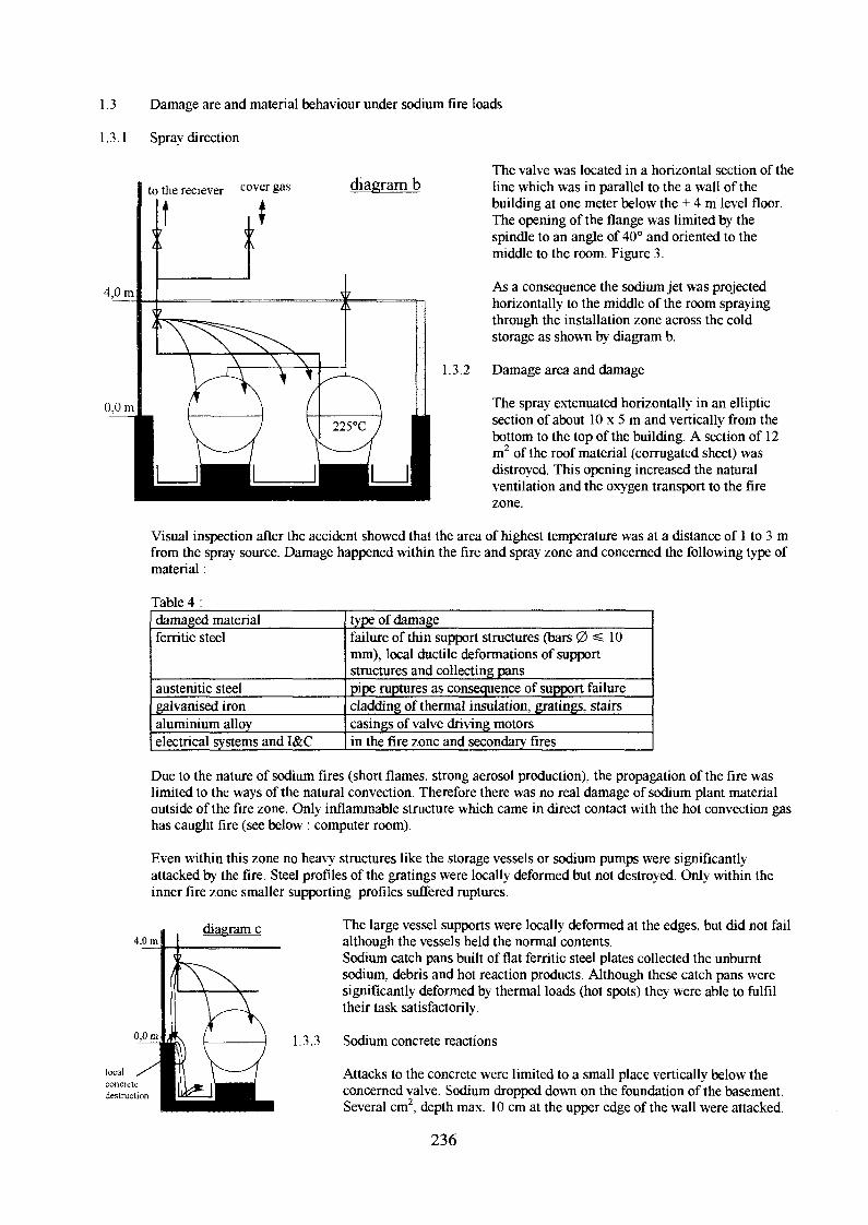
to the reciever cover gas diagram bThe valve was located in a horizontal section of theline which was in parallel to the a wall of thebuilding at one meter below the + 4 m level floor.The opening of the flange was limited by thespindle to an angle of 40° and oriented to themiddle to the room. Figure 3.
As a consequence the sodium jet was projectedhorizontally to the middle of the room sprayingthrough the installation zone across the coldstorage as shown by diagram b.
1.3.2 Damage area and damage
The spray extenuated horizontally in an ellipticsection of about 10 x 5 m and vertically from thebottom to the top of the building. A section of 12m2 of the roof material (corrugated sheet) wasdistroyed. This opening increased the naturalventilation and the oxygen transport to the firezone.
Visual inspection after the accident showed that the area of highest temperature was at a distance of 1 to 3 mfrom the spray source. Damage happened within the fire and spray zone and concerned the following type ofmaterial:
Table 4 :damaged materialferritic steel
austenitic steelgalvanised ironaluminium alloyelectrical systems and I&C
type of damagefailure of thin support structures (bars 0 =£ 10mm), local ductile deformations of supportstructures and collecting panspipe ruptures as consequence of support failurecladding of thermal insulation, gratings, stairscasings of valve driving motorsin the fire zone and secondary fires
Due to the nature of sodium fires (short flames, strong aerosol production), the propagation of the fire waslimited to the ways of the natural convection. Therefore there was no real damage of sodium plant materialoutside of the fire zone. Only inflammable structure which came in direct contact with the hot convection gashas caught fire (see below : computer room).
Even within this zone no heavy structures like the storage vessels or sodium pumps were significantlyattacked by the fire. Steel profiles of the gratings were locally deformed but not destroyed. Only within theinner fire zone smaller supporting profiles suffered ruptures.
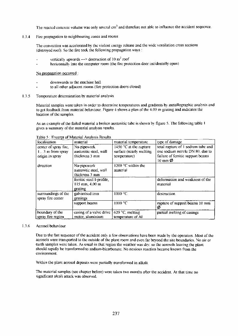
4,0 mdiagram c The large vessel supports were locally deformed at the edges, but did not fail
although the vessels held the normal contents.Sodium catch pans built of flat ferritic steel plates collected the unburntsodium, debris and hot reaction products. Although these catch pans weresignificantly deformed by thermal loads (hot spots) they were able to fulfiltheir task satisfactorily.
1.3.3 Sodium concrete reactions
Attacks to the concrete were limited to a small place vertically below theconcerned valve. Sodium dropped down on the foundation of the basement.Several cm2, depth max. 10 cm at the upper edge of the wall were attacked.
236
The reacted concrete volume was only several cm3 and therefore not able to influence the accident sequence.
1.3.4 Fire propagation to neighbouring zones and rooms
The convection was accelerated by the violent energy release and the wide ventilation cross sections(distroyed roof)- So the fire took the following propagation ways :
vertically upwards —> destruction of 10 m2 roof
horizontally into the computer room (the fire protection door incidentally open)
No propagation occurred :
downwards to the machine hallto all other adjacent rooms (fire protection doors closed)
1.3.5 Temperature determination by material analysis
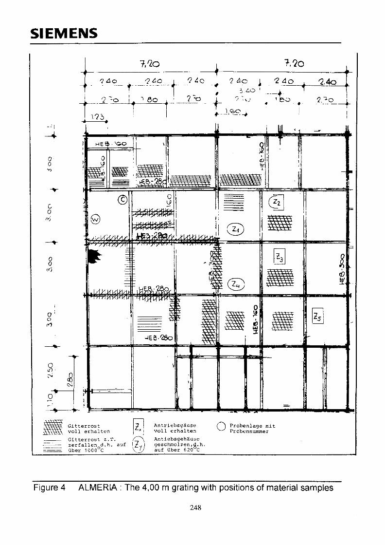
Material samples were taken in order to determine temperatures and gradients by metallographic analysis andto get feedback from material behaviour. Figure 4 shows a plan of the 4,00 m grating and indicates thelocation of the samples.
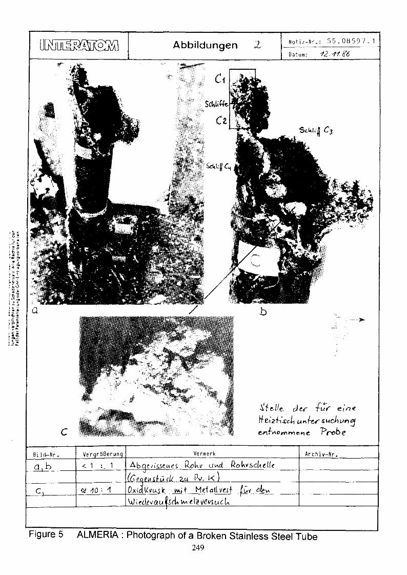
As an example of the failed material a broken austenitic tube is shown by figure 5. The following table 1gives a summary of the material analysis results.
Table 5 : Excerpt of Material Analysis Resultslocalisationcenter of spray fire,1... 3 m from sprayorigin in spray
direction
surroundings of thespray fire center
boundary of thespray fire region
materialNa-pipeworkaustenitic steel, wallthickness 3 mm
Na-pipeworkaustenitic steel, wallthickness 3 mmferritic steel I-profile,115 mm, 4,00 mgratinggalvanised irongratingssupport beams
casing of a valve drivemotor, aluminium
material temperature1450 °C at the rupturesurface (nearly meltingtemperature)
1200 °C within thematerial
1100°C
1100°C
620 °C, meltingtemperature of Al
type of damagetotal rupture of 1 sodium tube andone sodium nozzle DN 80. due tofailure of ferritic support beamsl O m m 0
deformation and weakness of thematerial
destruction
rupture of support beams 10 mm0partial melting of casings
1.3.6 Aerosol behaviour
Due to the fast sequence of the accident only a few observations have been made by the operators. Most of theaerosols were transported to the outside of the plant room and even far beyond the site boundaries. No air orearth samples were taken. As usual in that region the weather was dry; so the aerosols leaving the plantshould rapidly be transformed to sodium-bicarbonate. No noxious reaction became known from theenvironment.
Within the plant aerosol deposits were partially transformed in alkali.
The material samples (see chapter before) were taken two months after the accident. At that time nosignificant alcali attack was observed.
237
2 SODIUM FIRE ACCIDENT IN THE ILONA TEST FACILITY AT BENSBERG
This accident happened September 1992 in the sodium test facility at Bensberg in Germany. It has beenreported in the Fifth DeBeNe - Franco - PNC Specialists' Meeting on Sodium Fires and RadiologicalConsequences of Postulated LMFBR Accidents in March 1993. Karlsruhe. Germany.
ILONA was a large sodium test facility for natural convection in decay heat removal loops with down scaledcomponents (1/3) and full size elevation. The origin of the accident was not ILONA itself, but a provisionalinstallation in the basement of the ILONA plant.
2.1 Plant description
Building. Arrangement of ILONA:
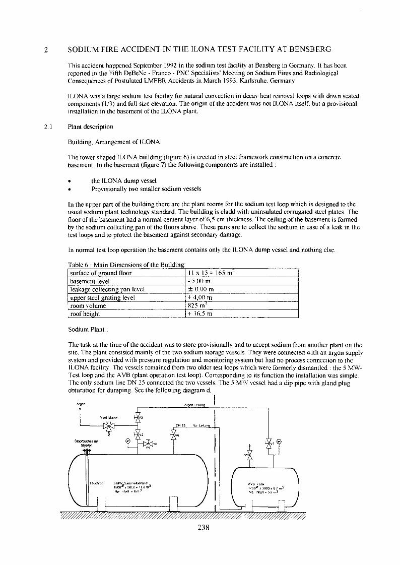
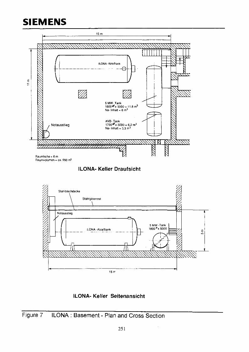
The tower shaped ILONA building (figure 6) is erected in steel framework construction on a concretebasement. In the basement (figure 7) the following components are installed :
• the ILONA dump vessel• Provisionally two smaller sodium vessels
In the upper part of the building there are the plant rooms for the sodium test loop which is designed to theusual sodium plant technology standard. The building is cladd with uninsulated corrugated steel plates. Thefloor of the basement had a normal cement layer of 6,5 cm thickness. The ceiling of the basement is formedby the sodium collecting pan of the floors above. These pans are to collect the sodium in case of a leak in thetest loops and to protect the basement against secondary damage.
In normal test loop operation the basement contains only the ILONA dump vessel and nothing else.
Table 6 : Main Dimensions of the Building:surface of ground floorbasement levelleakage collecting pan levelupper steel grating levelroom volumeroof height
11 x 15= 165 m2
- 5.00 m± 0,00 m+ 4,00 m825 m3
+ 36.5 m
Sodium Plant:
The task at the time of the accident was to store provisionally and to accept sodium from another plant on thesite. The plant consisted mainly of the two sodium storage vessels. They were connected with an argon supplysystem and provided with pressure regulation and monitoring system but had no process connection to theILONA facility. The vessels remained from two older test loops which were formerly dismantled : the 5 MW-Tcst loop and the AVB (plant operation test loop). Corresponding to its function the installation was simple.The only sodium line DN 25 connected the two vessels. The 5 M\V vessel had a dip pipe with gland plugobturation for dumping. See the following diagram d.
Argon Argon Leilung
238

Table 7 : Relevant Data of the Sodium Plant:
dimensionstotal volumeNa-contentscover gas operating pressurematerialinsulation/ temperaturecladdingelectrical heatingsodium line diameterothers
5 MW vessel1,8 m 0 x 5 m length11,8 mJ
6 m3
0,02 bar relative10 CrMo910140 mm/200 °CnoyesDN25dip line with gland plug
AVB vessel1,7 m 0 x 3 m length6,2 mJ
0,5 m3
10 CrMo910140 mm/200 °Cnoyes-
2.2 Origin and accident sequence
Preliminary remark : Due to the fact that the fire destroyed the pressure control and monitoring system andalso electrical systems, which were installed in the ILONA basement, no data recording from plant conditionsbefore and during the accident was available. However, by presence of other test facilities on the site data andinformation base of the ILONA accident is better than that of the ALMERIA accident.
In the original plant state the sodium contents of the vessels were frozen. In order to make the sodium transferthe sodium content of the 5 MW vessel was heated and melted by the electrical trace heaters on the vesselwall.
Table 8 : Initial state :sodium temperaturesodium volume in the vesseltotal gas volume in the vesselargon pressure control
< 100 °C6m J
6m J
1,02 bar
Due to a failure of the pressure regulation valves the cover gas control became unavailable during the heatingprocedure. The increasing gas pressure lifted the gland in the dip pipe and released sodium. About 6 hoursafter start of heating procedure the fire alarm from the ILONA basement was given by the central fire alarmsystem.
Probably the gland plug did not open completely the cross section of the dip pipe. A flow resistance remained.Therefore the leakage flow was small (the time which is necessary to melt the sodium may also play a role).Sodium and reaction products were flowing over the tank outside and came easily in contact with the tanksurface because there was no cladding. Additional reaction with insulation material and electrical equipmentmight have enhanced the energy release.
sodium leakage came in contact with the concrete floor and walls. A sodium concrete reaction started. Theconcrete of the walls spelled off by the thermal effect. The concrete of the floor was lifted by reaction productsand the thermal expansion of reinforcement steel.
The same phenomenon lifted the vessel at one end as well. By inclination of he vessel the entrance to the diptube of the vessel became uncovered and this stopped the leakage.
Table 9 : Leakage sequence data :leak rate (estimated value)duration of sodium leakagetotally leaked sodium masstotal duration of fire and sodium concrete reaction
0,2 kg/s5 hours4,0 t14 hours
239

Table 10phase
1
2
3
4
5
6
7
: Accidenhour/duration15. Sept13.30 h
18.00 h
19.00 h
16. Sept3.45
24.Septuntil25Oct.
t sequence and actionsphenomena
first alarm
local fire and aerosolproductionrestart of leakageand fire, strong heatand aerosol release
back ground noisefrom concretebursting,aerosol productiondecreasedfurther reduction ofaerosol release,
stop of burningphenomena, start ofcooling down phasetransformation ofaerosol deposits incarbonate
actions
local extinguishing seems to besuccessfulFurther attempts to extinguish. Holeswere cut in the catch pan at 0,00 mlevel in order to drop GRAPHEX.Argon injection with normal plantcover gas system.
Air sampling in the plantenvironment by local authorities.Extinguishing stopped due to heat andaerosol release.
Start of argon flooding from gastransport trucks.First inspections of the room withrespiratory equipment and heavyprotective suit.Argon cover gas inerting with slowlydecreasing argon flow.Temperature, Cb- and H2-monitoringstart of CQradmission
comments
mobile equipmentGRAPHEX
Available gas flow toosmall to cope with violentnatural convection.Negative result.
Obviously stop of sodiumleakage.
debris temperature450 °C;O2 < 2 % H2 < 0,7 %debris temperature100 °C;C Q , < 3 %
2.3 Consequences
2.3.1 Main characteristics of the fire
The leakage flow rate was small and there was not a "fountain". As found by post accident investigations theleakage sodium flowed along the vessel surface downwards and dropped on the concrete floor. There was noprotection by a steel cladding or sodium catch pan.
Consequently the behaviour was that of a pool fire with sodium concrete reaction at the floor.
Table 11 : Mass balance of leakage sodium :total leakage sodiumsodium implied in reaction with concreteunreacted sodium found in the debrisburnt sodiumsodium transformed in aerosolssodium transformed in other reaction products
4300 kg,_ 1000 kg
300 kg3000 kg2500 kg
500 kg
240
2.3.2 Damage area and damage
Table 12damaged materialdamaged materialferritic steel
ferritic material withgalvanised surfacetreatmentaluminiumconcreteelectrical systems and I&C
type of damageconstruction elementslocal ductile deformation of vessel support and thecollecting pan above the vesselpartial destruction of gratings and stairs
destruction of pressure control valves in the fire zonesee following chapter 1.3.3in the fire zone and secondary fires
There was no propagation of fire outside of the concerned plant room. Even within the plant room nodistraction occurred a short distance from the fire section and there was no horizontal propagation.
The sodium catch pan on the ceiling of the room was built of flat ferritic steel plates. This catch pan waslocally deformed by thermal loads (hot spots at the edge due to convection of hot reaction gas).
2.3.3 Sodium - concrete interactions
The most important observation of the site after the accident was the concrete distinction :sodium concrete reaction : mainly the floor of the room and the lower part of the wallthermal impact without chemical reaction : walls of the room in those areas which came in contactwith the convection flow of hot reaction gas,
2.3.3.1 Sodium concrete reaction
The concerned area was situated under the vessel, more precisely below the part of the vessel were the dippipe delivered the leakage flow. The concerned floor surface was about 20 m2.
There the sodium attacked the concrete to a depth of 390 mm. The reaction products increase the concretevolume. This was one of the effect which lifted the vessel and stopped finally the leak. The other was thermaldilatation of reinforcement steel. Exhaustive post accident analyses were made of the concrete damage. Figure8 shows a cross section and horizontal extent of the sodium - concrete reaction zone.
As maximum concrete temperatures 900 °C were found. In total 2 m3 of concrete reacted with sodium. Thereaction produced hydrogen. The hydrogen combustion increased the surface temperature of the vessel. Thiswas confirmed by lacquer replica technique.
2.3.3.1 Thermal effects
Chemical analyses of the wall concrete showed that only physically bound water was released. Nevertheless,this effect - together with thermal expansion effects - has destroyed 50 m2 of concrete wall. Without,however, calling in question the overall stability of the building. The reinforcement steel was much lessdeformed than that of the floor concrete. Figure 9 shows a damaged wall section.
2.3.4 Fire propagation to neighbouring zones and rooms
As stated in the previous chapters the fire impact was limited to the floor surface of 20 m2 and a wall surfaceof 50 m2.
No propagation occurred :
to the higher floors of the plant(insofar the sodium catch pan on the 0.00 m level was efficient in both directions : originallydesigned to protect the basement against leaks in the ILONA tower it was sufficient in the otherdirection as well).horizontally to other installations at the same room (example : the ILONA dump vessel).
241

2.3.5 Temperature determination by material analysis
Material samples were taken in order to determine temperatures and gradients and to get feedback frommaterial behaviour.
Table 13 : Extract of Material Analysis Results
2.3.6
materialvessel10CrMo910
reinforcement steel in floorconcrete reaction zoneBST500Ssodium collection pan at 0.00mferritic steelgalvanised iron gratingsILONA dump vesselaustenitic steel 1.4948
material temperaturelocally about 1000 °C
> 1000 °C
<800...900°C
1100 °C< 900... 1000 °C
type of damageno visual damage but localmodification ofmicrostructure (nearby themain fire zone)decrease of materialproperties
no damage, no modificationof microstructure
destructionno damage, no modificationof microstructure
Aerosol behaviour
In opposition to local damage of concrete aerosol deposits were found in the whole building.
Table 14 : Aerosol production balance :burnt sodiumsodium transformed in aerosolsdeposits in the buildingrelease to environment
3000 kg2500 kg1500 kg1000 kg
During the period of highest reaction rate the local authorities took air samples in the plant environment. Nonoxious reaction were found.
Deposits in the plant:The deposit layer thickness decrease with the floor level of the examined plant room.
4,20 m level29,40 m level
1,16 gram/nr0,44 gram/m^
Figure 10 shows photographs of aerosol deposits in plant rooms, which had obviously not suffered during theaccident.
Several months after the accident the ILONA building was cleaned. The cleaning was accompanied by-continuous chemical and material survey. After repair of the concrete damage the building was ready foranother use.
3 CODE DEVELOPMENT
Particularly the Almeria accident has accelerated R&D and code development with respect to spray fire andcombined spray - pool - fires. In Germany SIEMENS (former INTERATOM) developed the code NABRANDin order to discribe pool and spray fires simultaneously.
3.1 Modelization of energy release
From leakage accidents and a large variety of sodium fire experiments it was learnt that the most effectivethermodynamical consequences are produced by sodium jets dispersed after impact (like e.g. the spray fire atAlmeria). The code simulates the following input parameters :
leak rate242
fraction of the leak rate which participates in the spray fireextension of the spray zonepool burning area.
The sodium droplet size is an important parameter for the burning surface of a spray. The SPRAY subroutineneeds as input the droplet size. As a typical size spectrum a log-normal distribution with 4 mm meandiameter and a standard deviation of 2,15 has been identified to be valid for the single droplet burning model.The experiments showed that this is a good assumption for all types of dispersed fires from experiments.
3.3 Modelization of heat exchange
An important feature of the code is the natural convective and the radiative heat exchange between thecombustion zone and the aerosol loaden outer gas zone surrounding it. Because of the high heat absorption bythe produced aerosols, the heat transfer to the walls and structures of the compartment is done via the outergas zone. With respect to pressure relief and ventilation different options are possible. Also ID convectiveexchange between the compartments connected to the burning cell can be modelised.
3.3 Validation
In order to validate NABRAND code, pre- and postcalculations were compared to experiments that were donerecently in order to analyse combined fires at large leak rates in large containments. By these experiments thevalidation of NABRAND code already done for a large variety of different experiments mainly done fromFZK Karlsruhe and CEA Cadarache could be completed.
Table 15 : Sodium Spray Fire Experiments -Experiment
IGNA 402
IGNA 2002
IGNA 3602
IGNA 3604
FCA++2
post test:
FCA 150
post test:
Charactest cell data400 m3pressurerelief valves2 x 27 m3pressurerelief by 20,6m23600 m3
4 m2 burstdisc220 m3closed
220 m3closed220 m3closed
;eristicsspray data10 kg/s in 60s
135 kg/s in 8s
80 kg in 8 s
160/480
15,5 kg/s in25 s
15,5 kg/s in25 s150 kg/s in10 s
Comparison with NABRAND SimulationsPeak pre
testabout 0,03
cell 1 :0,13
cell 2 : 0,10
max. pressure
0,22/0,27 bar/s
3,2
32,8
ssure (bar)code<0,04
model 1 :cell 1 : 0,26cell 2 : 0,17Model 2 : 0.21
rise 0,17 bar/s
2,9...3,2
3,3
2,2...3,5
2,9
At spntestabout 20 soscillating
< 1 s
4,3 s
12...19s
6 s
jy timecode
0,3 s
4,3 s
3,3/2,6 s
9...15s
13 s
7s
5s
CONCLUSIONS
The two reported accidents found wide response in plant R&D, plant design and licensing. They covered twodifferent characteristics of a sodium release, the spray fire and sodium concrete reaction. When theALMERIA accident happened, spray fire codes had not yet been used in the plant design and licensing.Obviously ALMERIA has accelerateted R&D in this field.
Nearly all relevant phenomena (except reactivity and pressure built up in plant rooms) were present in theseevents. The German plant SNR 300 became the first where immediate consequences were drawn in R&D andlicensing (and sodium fires were one of the political pretexts for the authorities to impede licensing).NABRAND was one of the first codes which was applied in plant licensing as consequence of the ALMERIAaccident.
243

Dispite the spectacular consequences the lessons to be learnt from these fires are not only negative. Theaccidents happened in test facilities and not in nuclear plants designed in more onerous standard. So theconclusions concerning potential damage are conservative for nuclear plants :
no toxic release even if large quantities of aerosols are released (besides radioactivity, tritium...)propagation only by convection (and not by self sustaining reactions)no horizontal propagation beyond the immediate sodium fire zonedue to this fact protection measures against propagation are simple : normal fire resistant equipmentis sufficientall steel and concrete which is not in directly contact with the fire do not suffer functional relevantdamageseveral material groups such as aluminium and galvanised iron should be avoided for safety relevantequipmentplant rooms can easily be cleaned and subsequently used
The chief witness for these statements is the ILONA dump vessel : In fact one of the ALMERIA vessels wascleaned and requalified and raised from death as dump vessel for the ILONA test facility. As this presentationillustrates it survived a second large sodium fire without damage.
FIGURES
figure 1 ALMERIA : IEA - SSPS PROJECT CRS - Building Plansfigure 2 ALMERIA : Cross Section of the Damaged Valve LKO1 AA06figure 3 ALMERIA : Photographs of the Damaged Valve LKO 1 AA06figure 4 ALMERIA : View on the 4m level grating with positions of material samplesfigure 5 ALMERIA : Photograph of a broken stainless steel tubefigure 6 ILONA DHR Test Facilityfigure 7 ILONA Basement - Plan and Cross Sectionfigure 8 ILONA : Cross Section of the Sodium - Concrete Reaction Zone and Horizontal Extension of the
Fire Zonefigure 9 ILONA : View on a damaged Wall Sectionfigure 10 ILONA : Photographs of aerosol deposits in plant rooms
REFERENCES :
[1] Effects of Sodium Fires on Structures and Materials. Practical Experience with Sodium Leakage Accidents.K.F. Freudenstein, IAEA/IWGFR Obninsk, 1988
[2] The ILONA Sodium Fire Accident with Sodium Concrete Reaction (Preliminary Analysis). - K.F.Freudenstein, Proceedings of the Fifth DeBeNe - Franco - PNC Specialists' Meeting on Sodium Fires andRadiological Consequences of Postulated LMFBR Accidents. March 1993. Karlsruhe. Germany. (Notpublished proceedings)
244

SIEMENS
steam generator ;room
G i
SHTS h a l l
o o
PCS h a l l
•U
.A A
DCS process fj
area^ workshop ^
' I
V.'Z.'-CrJW.i VXJV.V.
f ijjmarshallingP/'diesel room ;> kiosk |
ibatteryi; J
: room
f.vs
H.V.-swi tchgear room
trans f ormerf!:
ill dining room
medical
r. L 1.. pi7 j - changingL 1L U-- lU -=f- 5~~ roomA toilets I ;-.
Figure 1 ALMERIA : IEA - SSPS PROJECT CRS - Building Plans
245
SIEMENS
X
Figure 2 ALMERIA :: Cross Section of the Damaged Valve LK01 AA06
246

SIEMENS
Figure 3 ALMERIA : Photographs of the Damaged Valve LK01 AA06
247
SIEMENS
Gitterrostvoll erhalten
—— Gitterrost z.T.^^ zerfallen d.h. auf— uber 1000°C
AntriebsgSusevoll erhalten
Antiebsgeha'usegeschinolzen <4-hauf Uber 620°C
o Probenlage mitProbennummer
Figure 4 ALMERIA : The 4,00 m grating with positions of material samples
248
Id
N o t i / - N r . : 5 5 . 0 8 5 9 7 . 1Abbildungen 2
Figure 5 ALMERIA : Photograph of a Broken Stainless Steel Tube249

SIEMENS
63,0 m
44.5 m
AuxiliaryBlowers
36.5m
0 m
•5 m
5 MW Tank
Natural Draught Stack
Air Outlet Damper
5 MW Sodium/Air-Heat-Exchanger
Inlet Louvers
Sodium-Main Piping Cold Leg
Sodium-Main Piping Hot Leg
Sodium Storage Vessel
5 MW Gas-Fired Sodium-Heater
3 MW Sodium/Air-Cooler
Electromagnetic Pump
2.5 MW Electric Sodium-Heater
Sodium Dump Tank
\
Offices
N Control room
ILONA
SURVEY
Figure 6 ILONA DHR Test Facility
250
SIEMENS15m
^ ^ s ^ ^ ^ ^ ^ ^
ILONA -AblaBtank
Notausstieg
Raumhdhe = 6 mRaumvolumen = ca. 990 n?
5 MW- Tank1800#x 5000 = 11,8 m3
Na- InhaK = 6 m3
AVB- Tank1700^x3000 -6 ,2 m3
Na- InhaN = 0,5 m3
m
ILONA- Keller Draufsicht
15m
ILONA- Keller Seitenansicht
Figure 7 ILONA : Basement - Plan and Cross Section
251

SIEMENS
Bauschutt undL6schpulver
^sbi^ilP65
800
Lage der Armierung Natrium - Betonreaktionszone
Schieflage des 5MW-Sammelbehalters nach dem Brand15 m
Raumhohe = 5 mRaumvolumen = ca. 825 rri3
Brandzone mit Schuttauflage
Figure 8 ILONA : Cross Section of the Sodium - Concrete Reaction Zone
252

SIEMENS
Figure 9 ILONA : View on a damaged Wall Section
253

SIEMENS
Buhne 3
ooa:
jQ.C
tnOa.D
2<o10
Q.
Ssoa.
3
Buhne 3
Buhne 2
Aerosolbelegung in der Aniage
254
Bildseite: 4


![Determination of sodium benzoate in fruit juicefac.ksu.edu.sa/sites/default/files/8_determination_of...Determination of sodium benzoate in fruit juice BCH445 [Practical] 1 •Food](https://img.pdfslide.us/doc/110x75/5aecc58f7f8b9ad73f901f0f/determination-of-sodium-benzoate-in-fruit-of-sodium-benzoate-in-fruit-juice-bch445.jpg)


![Sodium Phytate Presentation.pptx [Read-Only]formulatorsampleshop.com/v/reference/Sodium Phytate Presentation.pdfLaurate (Skin Conditioning Agent), Sodium Benzoate (Preservative), Sodium](https://img.pdfslide.us/doc/110x75/5eb52012fb0f3e0d55767ea6/sodium-phytate-read-onlyformulatorsampleshopcomvreferencesodium-phytate-presentationpdf.jpg)