Embed Size (px)
Citation preview
PNNL-10610 Ver. 1.5.3
Federal Emergency Management Information System (FEMIS) System Administration Guide for FEMIS Version 1.5.3 November 20 2002 Prepared for the CSEPP Office United States Army Soldier and Biological Chemical Command under a Related Services Agreement with the U.S. Department of Energy Contract DE-AC06-76RLO 1830

Acknowledgment The FEMIS product is being developed by the Pacific Northwest National Laboratory as part of the US Army’s Chemical Stockpile Emergency Preparedness Program (CSEPP). This software and its documentation were produced with Government support under Contract Number DE-AC06-76RLO-1830 awarded by the United States Department of Energy. The Government retains a paid-up non-exclusive, irrevocable worldwide license to reproduce, prepare derivative works, perform publicly and display publicly by or for the Government, including the right to distribute to other Government contractors. Disclaimer This material was prepared as an account of work sponsored by an agency of the United States Government. Neither the United States Government nor the United States Department of Energy, nor Battelle Memorial Institute, nor any of their employees, MAKES ANY WARRANTY, EXPRESSED OR IMPLIED, OR ASSUMES ANY LEGAL LIABILITY OR RESPONSIBILITY FOR THE ACCURACY, COMPLETENESS, OR USEFULNESS OF ANY INFORMATION, APPARATUS, PRODUCT, SOFTWARE, OR PROCESS DISCLOSED, OR REPRESENTS THAT ITS USE WOULD NOT INFRINGE PRIVATELY OWNED RIGHTS. References to any specific commercial product, process, or service by trade name, trademark, manufacturer, or otherwise does not necessarily constitute or imply endorsement, recommendation, or favoring by the US Army or Battelle. The software has not been reviewed for export out of the United States. A license or license exception may be required for export.
This document was printed on recycled paper.
PNNL-10610 Ver. 1.5.3
Federal Emergency Management Information System (FEMIS)
System Administration Guide for FEMIS v1.5.3 Robert A Burnett Daniel M Johnson Chitra Sivaraman Richard J Carter Ranata L Johnson Alex J. Stephan Tim R Downing Sharon M Johnson LaMar R Stoops Brian J Homer Robert M Loveall Blanche M Wood Nancy A Holter Stacy A Schulze November 20, 2002 Prepared for the CSEPP Office United States Army Soldier and Biological Chemical Command under a Related Services Agreement with the U.S. Department of Energy Contract DE-AC06-76RLO 1830 Pacific Northwest National Laboratory Richland, Washington 99352

Preface The Federal Emergency Management System (FEMIS)(a) is an emergency management planning and response tool. The following documents were developed to support system users. This FEMIS System Administration Guide provides information on FEMIS System Administrator activities as well as the utilities that are included with FEMIS. The FEMIS Data Management Guide provides the information needed to manage the data used to support the administrative, user-environment, database management, and operational capabilities of FEMIS. The FEMIS Installation Guide provides instructions for installing and configuring the FEMIS software package. The FEMIS Release Notes provide a description of what is new in the release and any information specific to this release that was not available when other documents were published. The FEMIS Bill of Materials defines FEMIS hardware, software, and communication requirements. The FEMIS Online Help System explains how to use the FEMIS program, which is designed to help emergency management personnel plan for and respond to a Chemical Accident or Incident (CAI) Event at a military chemical stockpile. For System and Database Administrators, the Troubleshooting Guide consists of error messages and known problems as well as suggestions to resolve these errors and problems.
(a) The FEMIS program is being developed by the Pacific Northwest National Laboratory as part of the
US Army Chemical Stockpile Emergency Preparedness Program (CSEPP). Pacific Northwest National Laboratory is operated for the US Department of Energy by Battelle under Contract DE-AC06-76RLO 1830.
iii
Contents 1.0 Overview................................................................................................................................ 1-1 1.1 Point of Contact .......................................................................................................... 1-2 1.2 Document Organization................................................................................................. 1-2 1.3 Software Products .......................................................................................................... 1-3 2.0 FEMIS Monitoring Tools....................................................................................................... 2-1 2.1 AutoRecovery ................................................................................................................ 2-2 2.1.1 How to Execute AutoRecovery......................................................................... 2-2 2.1.2 Messaging Service ............................................................................................ 2-4 2.1.3 FEMIS Logging ................................................................................................ 2-4 2.1.4 FEMIS Log File Archive .................................................................................. 2-5 2.1.5 Sending E-mail.................................................................................................. 2-5 2.1.6 AutoRecovery “Watchdog” Timeout Parameter............................................... 2-5 2.1.7 AutoRecovery Database Monitoring Parameters.............................................. 2-6 2.1.8 Dynamic Insertion/Deletion of Remote Server in Replication ......................... 2-7 2.1.9 AutoRecovery Events/Actions .......................................................................... 2-7 2.1.10 Detecting System Problems with AutoRecovery .............................................. 2-12 2.1.11 Using AutoRecovery......................................................................................... 2-12 2.2 UNIX FEMIS Monitor................................................................................................... 2-14 2.2.1 Background ....................................................................................................... 2-14 2.2.2 UNIX FEMIS Monitor Configuration File ....................................................... 2-14 2.2.3 UNIX FEMIS Monitor Scripts.......................................................................... 2-16 2.2.4 UNIX FEMIS Monitor Daemon Program......................................................... 2-17 2.2.5 UNIX FEMIS Monitor Client Program ............................................................ 2-17 2.3 FEMISMon Watcher (FWATCH.EXE) ........................................................................ 2-18 2.3.1 Notification Status............................................................................................. 2-18 2.3.2 Menu Options.................................................................................................... 2-18 2.4 FEMIS Monitor PC (FMONPC.EXE)........................................................................... 2-19 2.4.1 Replication Status ............................................................................................. 2-19 2.4.2 Options Menu.................................................................................................... 2-20 2.5 Network Monitor (WS_WATCH.EXE) ........................................................................ 2-21 3.0 FEMIS Notification Service................................................................................................... 3-1 3.1 UNIX Host Notification Service.................................................................................... 3-1 3.1.1 UNIX Notification Service ............................................................................... 3-2 3.1.1.1 Executable Binary Files .................................................................... 3-3 3.1.1.2 Configuration Data File .................................................................... 3-3 3.1.1.3 Service Port Data File ....................................................................... 3-3 3.1.1.4 Protocol Numbers ............................................................................. 3-3 3.1.1.5 Daemon Server Startup ..................................................................... 3-4
v
Federal Emergency Management FEMIS System Administration Guide Information Systems (FEMIS) November 20, 2002–Version 1.5.3
3.1.2 Notification Server Configuration Options....................................................... 3-4 3.1.2.1 Command-line Options..................................................................... 3-4 3.1.2.2 Clone Process in Background Option ............................................... 3-5 3.1.2.3 Display Version Options................................................................... 3-5 3.1.2.4 Diagnostic and Quiet Modes............................................................. 3-5 3.1.2.5 Service Port Name Option ................................................................ 3-6 3.1.2.6 Service Port Environment Option..................................................... 3-6 3.1.2.7 Display IP Address and Service Port ................................................ 3-6 3.1.2.8 Enable Log Files ............................................................................... 3-6 3.1.2.9 Nonstandard Port from Command Line............................................ 3-7 3.1.2.10 Connecting to Other EOC’s Notification Server .............................. 3-7 3.1.2.11 Multiple Remote EOC Servers Limitation........................................ 3-7 3.1.2.12 Server to Server Connection ............................................................. 3-7 3.1.2.13 Which Service Port to Use................................................................ 3-9 3.1.2.14 Enable Keep Alive ............................................................................ 3-10 3.1.2.15 Registered and Unregistered Service Port ........................................ 3-10 3.1.3 femis_event EVENT Configuration File .......................................................... 3-10 3.1.4 Notification Server Utilities .............................................................................. 3-12 3.1.4.1 UNIX Client Application – fev......................................................... 3-12 3.1.4.2 UNIX Client Command-line Options ............................................... 3-12 3.1.4.3 Client ID Number ............................................................................. 3-12 3.1.4.4 UNIX Client Protocol ....................................................................... 3-13 3.1.4.5 UNIX Client Example....................................................................... 3-13 3.1.4.6 UNIX Client Diagnostics.................................................................. 3-14 3.1.4.7 UNIX Client Information Diagnostic $i ........................................... 3-15 3.1.4.8 UNIX Client Socket Connections Diagnostic $s .............................. 3-16 3.1.4.9 UNIX Client Auxiliary Connect Information Diagnostic $aux ........ 3-17 3.1.4.10 UNIX Client Remote Servers Diagnostic $rem................................ 3-18 3.1.4.11 UNIX Client Event Board Diagnostic $eve...................................... 3-18 3.1.4.12 UNIX Client Synchronize Action $sync........................................... 3-19 3.1.4.13 Data Driven Notification Command Line Arguments ...................... 3-19 3.2 PC Notification Service ................................................................................................. 3-20 3.2.1 PC Notification Service Overview.................................................................... 3-20 3.2.1.1 Executable Binary Files .................................................................... 3-20 3.2.1.2 Notification Service Startup.............................................................. 3-21 3.2.2 PC Notification Service Configuration Options ............................................... 3-21 3.2.2.1 Configuration Parameters ................................................................. 3-21 3.2.2.2 Notification Service Configuration File............................................ 3-21 3.2.2.3 Command-line Options..................................................................... 3-22 3.2.2.4 Environment Variables ..................................................................... 3-22 3.2.2.5 Host Server Name and Port............................................................... 3-22 3.2.3 PC Notification Service Operation.................................................................... 3-22 3.2.3.1 Notification Service Window ........................................................... 3-22 3.2.3.2 Lost Connections .............................................................................. 3-24
vi

Federal Emergency Management FEMIS System Administration Guide Information Systems (FEMIS) November 20, 2002–Version 1.5.3
3.2.4 PC Notification Test Client............................................................................... 3-24 3.2.4.1 PC Test Client – NOTITEST.EXE ................................................... 3-24 3.2.4.2 PC Test Client Configuration............................................................ 3-24 3.2.4.3 PC Test Client Command-line Options ............................................ 3-24 3.2.4.4 PC Test Client Functions .................................................................. 3-25 3.2.4.5 PC Test Client Diagnostics ............................................................... 3-26 3.2.5 Notification Server Troubleshooting................................................................. 3-27 3.2.5.1 Check Notification Server Active..................................................... 3-27 3.2.5.2 Check Notification Server Communication...................................... 3-27 3.2.5.3 Aborting Notification Server ............................................................ 3-28 3.2.5.4 Fixing Notification Port .................................................................... 3-29 3.2.5.5 PC WinSock Errors........................................................................... 3-29 3.3 Starting/Stopping Notification Service .......................................................................... 3-30 3.3.1 Starting Notification Service............................................................................. 3-31 3.3.2 Stopping Notification Service ........................................................................... 3-31 3.4 Data Transfer Notification ............................................................................................. 3-32 3.4.1 Data Acknowledgement Notification Window................................................. 3-32 3.4.2 Data Acknowledgement Monitoring Window.................................................. 3-32 4.0 FEMIS Command Server ......................................................................................................... 4-1 4.1 cmdservd – FEMIS Command Server Daemon............................................................... 4-1 4.1.1 Synopsis .............................................................................................................. 4-1 4.1.2 Availability ......................................................................................................... 4-1 4.1.3 Description.......................................................................................................... 4-1 4.1.4 Options................................................................................................................ 4-2 4.1.5 Syntax Check ...................................................................................................... 4-3 4.1.6 Installation........................................................................................................... 4-6 4.1.7 Protocol ............................................................................................................. 4-7 4.1.8 Messages ........................................................................................................... 4-7 4.1.8.1 Message Format ................................................................................ 4-7 4.1.8.2 Message Fields.................................................................................. 4-8 4.1.8.3 Operation Codes ............................................................................... 4-8 4.1.8.4 Command Message........................................................................... 4-9 4.1.8.5 Error Messages ................................................................................. 4-9 4.1.8.6 Reply Messages ................................................................................ 4-10 4.1.8.7 Alert Messages.................................................................................. 4-11 4.1.8.8 Message Example ............................................................................. 4-11 4.1.9 Service Port and Name...................................................................................... 4-12 4.1.10 Files................................................................................................................... 4-12 4.2 cmdserv.conf – FEMIS Command Server Configuration File ...................................... 4-12 4.2.1 Availability ....................................................................................................... 4-12 4.2.2 Description........................................................................................................ 4-12 4.2.3 Syntax ............................................................................................................... 4-13
vii
Federal Emergency Management FEMIS System Administration Guide Information Systems (FEMIS) November 20, 2002–Version 1.5.3
4.2.4 Block Syntax ..................................................................................................... 4-14 4.2.4.1 ACCESS Block................................................................................. 4-15 4.2.4.2 HOST Block ..................................................................................... 4-15 4.2.4.3 SITE Block ....................................................................................... 4-16 4.2.4.4 ALL Block ........................................................................................ 4-17 4.2.4.5 ENTRY Block................................................................................... 4-17 4.2.5 Directive Syntax and Semantics........................................................................ 4-18 4.2.5.1 Site Directive .................................................................................... 4-19 4.2.5.2 Executable Directive......................................................................... 4-19 4.2.5.3 Directory Directive ........................................................................... 4-20 4.2.5.4 Password Directive ........................................................................... 4-20 4.2.5.5 Outfile Directive ............................................................................... 4-21 4.2.5.6 Errfile Directive ................................................................................ 4-22 4.2.5.7 Argument Directive .......................................................................... 4-22 4.2.5.8 Environment Directive...................................................................... 4-23 4.2.5.9 File Directive .................................................................................... 4-24 4.2.5.10 Put Directive ..................................................................................... 4-24 4.2.5.11 Allow Directive................................................................................. 4-25 4.2.5.12 Deny Directive .................................................................................. 4-25 4.3 cmdserv – FEMIS Command Server Test Client (UNIX)............................................. 4-26 4.3.1 Synopsis ............................................................................................................ 4-26 4.3.2 Availability........................................................................................................ 4-26 4.3.3 Description ........................................................................................................ 4-26 4.3.4 Options .............................................................................................................. 4-26 4.3.5 Installation......................................................................................................... 4-27 4.3.6 Protocol ............................................................................................................. 4-27 4.3.7 Operation .......................................................................................................... 4-27 4.3.8 Messages ........................................................................................................... 4-30 4.3.9 Configuration File ............................................................................................. 4-30 4.3.10 Service Port and Name...................................................................................... 4-30 4.3.11 Files................................................................................................................... 4-30 5.0 FEMIS Meteorological Application....................................................................................... 5-1 5.1 Meteorological Input Using the FEMIS DEI................................................................... 5-1 5.2 Meteorological Input Via the FEMIS Met Data .............................................................. 5-1 6.0 FEMIS Contact Daemon ........................................................................................................ 6-1 6.1 Message Format ............................................................................................................ 6-1 6.2 Configuration File............................................................................................................ 6-1 7.0 FEMIS Data Exchange Interface (DEI) ................................................................................. 7-1 7.1 Software and Hardware Components .............................................................................. 7-1 7.1.1 Software Components ....................................................................................... 7-1 7.1.2 Hardware Components...................................................................................... 7-1
viii
Federal Emergency Management FEMIS System Administration Guide Information Systems (FEMIS) November 20, 2002–Version 1.5.3
7.2 Program Detail – femisdei ............................................................................................. 7-1 7.2.1 Startup Phase..................................................................................................... 7-2 7.2.2 Processing Loop Phase...................................................................................... 7-2 7.2.3 Shutdown Phase ................................................................................................ 7-3 7.3 Program Detail – fprofdei .............................................................................................. 7-4 7.4 Configuring the Programs.............................................................................................. 7-4 7.4.1 Configuration – femisdei .................................................................................. 7-4 7.4.1.1 femisdei UNIX User Account........................................................... 7-5 7.4.1.2 femisdei FTP Profile File.................................................................. 7-5 7.4.1.3 femisdei Configuration File .............................................................. 7-5 7.4.2 Configuration – fprofdei ................................................................................... 7-9 7.5 Operation ....................................................................................................................... 7-9 7.5.1 Operation – femisdei ......................................................................................... 7-9 7.5.2 Operation – fprofdei.......................................................................................... 7-9 7.6 Purging Old Data ........................................................................................................... 7-10 7.7 DEI Troubleshooting ..................................................................................................... 7-11 7.7.1 Troubleshooting – femisdei .............................................................................. 7-11 7.7.2 Troubleshooting – fprofdei ............................................................................... 7-11 8.0 FEMIS GIS Database............................................................................................................. 8-1 8.1 Spatial Data Description ................................................................................................ 8-1 8.2 Spatial Data Maintenance .............................................................................................. 8-1 8.3 GIS Utilities ................................................................................................................... 8-2 8.3.1 Loading the GIS Utilities .................................................................................. 8-2 8.3.2 Opening the GIS Utilities.................................................................................. 8-3 8.4 Zone Editor .................................................................................................................... 8-3 8.4.1 Editing the Zone Theme.................................................................................... 8-4 8.4.2 Updating the FEMIS Database ......................................................................... 8-8 8.4.3 Distributing the New Zone Files ....................................................................... 8-9 8.5 General Hazard Theme (GIS Zone Theme) Definition ................................................. 8-9 8.5.1 Adding a New General Hazard Theme ............................................................. 8-9 8.5.2 General Hazard Database Reports .................................................................... 8-10 8.5.3 Modifying General Hazard Theme Display Attributes ..................................... 8-11 8.5.4 Distributing the New GIS FEMISGIS.INI and Symbol Lookup Changes........ 8-13 8.6 GIS Configuration.......................................................................................................... 8-13 8.6.1 Symbol Lookup Table....................................................................................... 8-14 8.6.2 Symbol Defaults................................................................................................ 8-15 8.7 Customizing the FEMIS Map ........................................................................................ 8-15 8.7.1 Customizing the FEMISGIS.INI File ............................................................... 8-16 8.7.2 Altering the Default FEMIS Map ..................................................................... 8-19 8.7.3 GIS Configuration Editor.................................................................................. 8-20 8.7.4 Theme Projection Utility................................................................................... 8-20 8.7.5 Adding Orthophotos.......................................................................................... 8-22 8.8 Backup Procedures ........................................................................................................ 8-22
ix
Federal Emergency Management FEMIS System Administration Guide Information Systems (FEMIS) November 20, 2002–Version 1.5.3
9.0 FEMIS Oracle Database......................................................................................................... 9-1 9.1 Data Description ............................................................................................................ 9-1 9.2 Replication ..................................................................................................................... 9-2 9.3 Database Maintenance ................................................................................................... 9-2 9.4 How AutoRecovery Works with the Database .............................................................. 9-3 10.0 Server Network Time Protocol (NTP) Set Up ....................................................................... 10-1 11.0 Security Measures .................................................................................................................. 11-1 11.1 UNIX Server Security.................................................................................................... 11-1 11.1.1 Software Patches ............................................................................................... 11-1 11.1.2 Shared Directories............................................................................................. 11-1 11.2 Database Security .......................................................................................................... 11-1 11.2.1 Replication Schema........................................................................................... 11-2 11.2.2 Modifications to the Manage Database Passwords Tool .................................. 11-2 12.0 Backup Strategy for FEMIS................................................................................................... 12-1 12.1 Recommended Backup Strategy .................................................................................... 12-1 12.1.1 File System Backups......................................................................................... 12-1 12.1.1.1 Full File System Backups ................................................................. 12-2 12.1.1.2 Incremental File System Backups..................................................... 12-2 12.1.2 File System Backup Procedures for the UNIX Server ...................................... 12-2 12.1.3 Oracle Database Backups.................................................................................. 12-4 12.1.3.1 Cold Full Backups of the Oracle Database ....................................... 12-5 12.1.3.2 Hot Full Backups of the Oracle Database......................................... 12-5 12.1.3.3 Logical Backups of the Oracle Database .......................................... 12-6 12.1.4 External Storage of Folders and Deletion of Old Folder Data .......................... 12-6 12.1.5 Managing the FEMIS Log Files........................................................................ 12.7 12.2 System Backups for Sun Solaris System ....................................................................... 12-7 13.0 FEMIS UNIX Server.............................................................................................................. 13-1 13.1 Maintenance of the FEMIS UNIX Server ..................................................................... 13-1 13.1.1 Monitor Oracle and FEMIS .............................................................................. 13-1 13.1.2 Perform System Backups .................................................................................. 13-1 13.2 Troubleshooting the FEMIS UNIX Server .................................................................... 13-1 13.2.1 FEMIS Troubleshooting ................................................................................... 13-1 13.2.2 Samba Services ................................................................................................. 13-2 13.2.2.1 Samba User Authentication .............................................................. 13-2 13.2.2.2 NFS and Samba Interaction .............................................................. 13-3 13.2.2.3 FEMIS Samba Directory Structure ................................................... 13-4 14.0 FEMIS PC Utilities ................................................................................................................ 14-1 14.1 FSTARTUP................................................................................................................. 14-1 14.2 FUPDATE.BAT.......................................................................................................... 14-1 14.3 WINECHO.................................................................................................................. 14-2 14.4 FIXINI......................................................................................................................... 14-2
x
Federal Emergency Management FEMIS System Administration Guide Information Systems (FEMIS) November 20, 2002–Version 1.5.3
14.5 WRITEREG................................................................................................................ 14-3 14.6 WRITEINI .................................................................................................................. 14-3 14.7 MSGBOX ................................................................................................................... 14-4 14.8 AUTOEXNT............................................................................................................... 14-5 14.9 NTPQ .......................................................................................................................... 14-5 14.10 NTPDATE .................................................................................................................. 14-6 14.11 INSTSRV.................................................................................................................... 14-6 14.12 SWITCHDB................................................................................................................ 14-6 14.13 FUNITCVT................................................................................................................. 14-6 14.14 Stand-Alone Watchful Eye ......................................................................................... 14-7 14.15 Remote Evacuee Registration ..................................................................................... 14-7
xi

Federal Emergency Management FEMIS System Administration Guide Information Systems (FEMIS) November 20, 2002–Version 1.5.3
Tables 1.1 Integrated COTS Software Products ...................................................................................... 1-3 7.1 Sample femisdei.cfg File........................................................................................................ 7-12 7.2 femisdei Command Line Options .......................................................................................... 7-13
Figures 2.1 AutoRecovery’s Integration of Monitoring, Notification, and Recovery .............................. 2-3 2.2 FEMIS Monitor/PC Window ................................................................................................. 2-20 3.1 FEMIS Notification Service Window.................................................................................... 3-23 3.2 Notification Service Test Window......................................................................................... 3-25
xii

Acronyms and Definitions ACTS Automated Computer Time Service API application program interface APR Project file format (ArcView) CAI Chemical Accident or Incident COTS Commercial-Off-The-Shelf CSEPP Chemical Stockpile Emergency Preparedness Program D2PC Chemical wind dispersion model used in FEMIS DBMS Database Management System DDN Data Driven Notification DEI Data Exchange Interface DLL Dynamic Linked Library DSN Data Source Name E-mail electronic mail EMIS Emergency Management Information System EOC Emergency Operations Center FEMIS Federal Emergency Management Information System FTP File Transfer Protocol GB gigabyte–billion bytes GID Group Identification number GIS geographic information system GMT Greenwich Mean Time GPS Global Positioning System IANA Internet Assigned Number Authority IEM Innovative Emergency Management, Inc. ID identification number IP Internet Protocol KB kilobyte–thousand bytes LAN local area network MB megabyte–million bytes Met meteorological MHz megahertz–millions of cycles per second NFS Network File System NIST National Institute of Standards and Technology NTP Network Time Protocol PC personal computer PDC Primary Domain Controller PID process identification number PNNL Pacific Northwest National Laboratory PPP Point to Point Protocol RER Remote Evacuee Registration RDBMS relational database management system SBCCOM US Army Soldier and Biological Chemical Command
xiii
Federal Emergency Management FEMIS System Administration Guide Information System (FEMIS) November 20, 2002–Version 1.5.3
xiv
SQL Structured Query Language SQL script Sequence of SQL statements that perform database operations TCP/IP Transmission Control Protocol/Internet Protocol UDP User Datagram Protocol UID User Identification number UNIX Generic name for the server operating system UTM Universal Transverse Mercator WAN wide area network Windows NT Microsoft Network Operating System for Workstations Windows 2000 Microsoft Operating System WinSock Windows Sockets WWV NIST radio station broadcasting continuous time status

1.0 Overview The Federal Emergency Management Information System (FEMIS©)(a) is an emergency management planning and response tool that was developed by the Pacific Northwest National Laboratory(b) (PNNL) under the direction of the US Army Soldier and Biological Chemical Command (SBCCOM). This System Administration Guide for FEMIS Version 1.5.3 provides information necessary for your System Administrator to maintain the FEMIS system. The FEMIS system is designed for a single Chemical Stockpile Emergency Preparedness Program (CSEPP) site that has multiple Emergency Operations Centers (EOCs). Each EOC has personal computers (PCs) that emergency planners and operations personnel use to do their jobs. These PCs are connected via a local area network (LAN) to servers that provide EOC-wide services. Each EOC is interconnected to other EOCs via a wide area network (WAN). Thus, FEMIS is an integrated software product that resides on client/server computer architecture. The main body of FEMIS software, referred to as the FEMIS application software, resides on the PC client(s) and is directly accessible to emergency management personnel. The remainder of the FEMIS software, referred to as the FEMIS support software, resides on the UNIX server. The support software provides the communication, data distribution, and notification functionality necessary to operate FEMIS in a networked, client/server environment. The UNIX server provides an Oracle relational database management system (RDBMS) service, basic file management services, and ARC/INFO GIS (geographic information system) capabilities (which is optional). PNNL developed utilities, which reside on the server, include the Notification Service, the Command Service that executes AutoRecovery. This client software includes the FEMIS application, government furnished dispersion model, and Commercial-Off-The-Shelf (COTS) software applications, such as the ArcView GIS. The FEMIS PC software accesses the site-specific database on the server and returns data to the PC. The user can then add, edit, or delete information; make decisions; displays maps; or use other FEMIS functionality. Information is passed back to the FEMIS database and notifications are made to other FEMIS users. To operate FEMIS, the application software must have access to a site-specific FEMIS emergency management database. Data that pertains to an individual EOC’s jurisdiction is stored on the EOC’s local server. Information that needs to be accessible to all EOCs is automatically distributed by the FEMIS database to the other EOCs at the site.
(a) FEMIS software was copyrighted in 1995 by Battelle Memorial Institute. (b) Pacific Northwest National Laboratory is operated for the US Department of Energy by Battelle Memorial
Institute under Contract DE-AC06-76RLO 1830.
1-1

Federal Emergency Management FEMIS System Administration Guide Information Systems (FEMIS) November 20, 2002–Version 1.5.3
The FEMIS databases have been developed in conjunction with Innovative Emergency Management, Inc. (IEM) and the personnel at each site. The validated database will be provided by PNNL when FEMIS is installed at your site. Please refer to the Database Management Guide for FEMIS Version 1.5.3 for further information. Proper installation of the FEMIS software is crucial to the operations of the emergency management system. Many software elements must be installed on a variety of servers and client workstations. Each must be installed and configured according to specifications for proper interoperability. Please refer to the Installation Guide for FEMIS Version 1.5.3 for further information on installation, including directory structures and other configurations.
1.1 Point of Contact We encourage you to contact us with suggestions or to ask questions. You can contact us by mail, telephone, or E-mail: Julie Raye Dunkle Pacific Northwest National Laboratory P.O. Box 999, MS K7-28 Richland, WA 99352 Telephone: (509) 375-2245 E-Mail address: [email protected]
1.2 Document Organization This document is organized into 14 sections, as follows: Section 1.0 – Overview – discusses the FEMIS software system. Section 2.0 – FEMIS Monitoring Tools – describes how to use the FEMIS monitoring tools to
check the status of database replication and the system. Section 3.0 – FEMIS Notification Service – describes the FEMIS Notification Service that is used
to coordinate new data input. Section 4.0 – FEMIS Command Server – describes the FEMIS Command Service, which is used
by PCs to launch the AutoRecovery. Section 5.0 – FEMIS Meteorological Application – describes the FEMIS meteorological
application. Section 6.0 – FEMIS Contact Daemon – discusses the FEMIS contact protocol used in all network
communication.
1-2

Federal Emergency Management FEMIS System Administration Guide Information Systems (FEMIS) November 20, 2002–Version 1.5.3
1-3
Section 7.0 – FEMIS Data Exchange Interface (DEI) – discusses the FEMIS Data Exchange Interface application, which is used to support the transfer of data from the Emergency Management Information System (EMIS) to FEMIS.
Section 8.0 – FEMIS GIS Database – describes the FEMIS GIS database and the components of
the spatial database. Section 9.0 – FEMIS Oracle Database – describes the FEMIS Oracle database which manages the
relational database and replication. Section 10.0 – Server Network Time Protocol Set Up – describes how to set up and synchronize the
server time. Section 11.0 – Security Measures – describes UNIX server and database security. Section 12.0 – Backup Strategy for FEMIS – discusses the recommended backup strategy for file
system and Oracle database backups. Section 13.0 – FEMIS UNIX Server – discusses the maintenance and troubleshooting for the
FEMIS UNIX server. Section 14.0 – FEMIS PC Utilities – describes the utilities available with the FEMIS application.
1.3 Software Products FEMIS integrates the following COTS software products.
Table 1.1. Integrated COTS Software Products
Software Application Software Company ArcView GIS Environmental Systems Research Institute, Inc. (ESRI) Microsoft Windows 2000/XP/NT Microsoft Corporation Oracle and Oracle ODBC Driver Oracle Corporation Samba Samba Team (open source project) Solaris Sun Microsystems, Inc.
FEMIS integrates the following government-furnished software products. D2PC (February 2000) US Army SBCCOM PARDOS v3.1 (May 1997) US Army SBCCOM

2.0 FEMIS Monitoring Tools The FEMIS decision support system uses a networked, client/server architecture that requires the management of multiple servers, LAN and WAN networks, replicated relational databases, and onpost-to-offpost communications. As such, System Administrators must have a suite of tools at their disposal that will allow them to effectively identify and resolve problems as they arise in the extended FEMIS architecture. Interruptions in FEMIS services can result from network problems, such as • Unpredicted events (power failures) may result in server shutdowns • Critical functions including the Oracle databases may cease to operate • Communication services provided by other servers (such as Met, DEI, or EMIS) may be
inactive. Distributed processing in FEMIS relies on all EOC servers working properly and the network interconnecting them being reliable. As a result, the system should be monitored regularly to detect any abnormal conditions and to avoid problems. This section describes the tools provided to assist the FEMIS System Administrator in supporting the extended FEMIS architecture. These tools assist in monitoring the system, notifying the FEMIS System Administrator that a problem exits, and, if applicable, automatic repair of system problems. These tools include the following: AutoRecovery AutoRecovery is a UNIX tool, run as a cron job that monitors the status of the extended FEMIS architecture and can intrusively notify the System Administrator when there is a significant problem. Where applicable, AutoRecovery will identify and fix problems automatically. AutoRecovery provides both a log and notifications on the status of extended FEMIS architecture. UNIX FEMIS Monitor The UNIX FEMIS Monitor provides the status of the FEMIS and database UNIX processes. This UNIX FEMIS monitoring subsystem is secure and will not allow outside access to the FEMIS network via the monitoring subsystem. FEMISMon Watcher (FWATCH.EXE) FEMISMon Watcher or FWATCH is a PC application that receives notifications from AutoRecovery and graphically displays the status of key FEMIS system components. FWATCH has triggers that will evoke alarms to notify the System Administrator if AutoRecovery detects a significant problem.
2-1
Federal Emergency Management FEMIS System Administration Guide Information Systems (FEMIS) November 20, 2002–Version 1.5.3
FEMIS Monitor PC (FMONPC.EXE) FEMIS Monitor PC is a PC application that checks FEMIS database replication and displays a graphic representation of replication status. Network Monitor (WS_WATCH.EXE) Network Monitor is a PC application that graphically depicts the status of the FEMIS network.
2.1 AutoRecovery The FEMIS AutoRecovery system is an integrated system that monitors the extended FEMIS architecture, notifies your System Administrator if significant problems arise, and fixes problems that can be automatically repaired. Figure 2.1 illustrates the flow of the monitoring, notification, and recovery effort. The AutoRecovery system was developed to reduce the involvement of the FEMIS System Administrator in maintaining the system, aid in the identification of problems when they arise, and keep the system up and operating with fewer interruptions. With AutoRecovery, the ability to repair and/or restart FEMIS processes has been provided along with increased identification capabilities. It is recommended that AutoRecovery be installed on each of the servers in the FEMIS network. When that has been completed, the status of all processes tracked by AutoRecovery is recorded in a log on each of the servers every time AutoRecovery executes. Whenever an anomalous event occurs (e.g., database shuts down, network crashes) a log entry is made and an E-mail message is sent to all AutoRecovery custodians (See Sections 2.1.3, FEMIS Logging, 2.1.4, FEMIS Log File Archive, and 2.1.5, Sending E-mail) if so configured. Included in the E-mail message is AutoRecovery’s attempt at fixing the problem, if AutoRecovery has been configured to correct the specific problem. For example, when the database listener goes down, AutoRecovery attempts to restart it. It reports that it tried to restart it and reports whether or not it successfully did so. 2.1.1 How to Execute AutoRecovery AutoRecovery is invoked via the cron facility. Entries in the root crontab file automatically invoke AutoRecovery on the following default schedule. Mon thru Fri 7:00a to 6:00p - run AutoRecovery every ten minutes 6:00p to 7:00a - run AutoRecovery every half hour Sat & Sun - run AutoRecovery hourly
To change the run schedule, edit the root crontab (See the man page on crontab).
2-2

Federal Emergency Management FEMIS System Administration Guide Information Systems (FEMIS) November 20, 2002–Version 1.5.3
Figure 2.1. AutoRecovery’s Integration of Monitoring, Notification, and Recovery
Start
Launch Watchdog
Watch Dog
Sleep
Send signal
StatusOK?
END
Process Configuration
Get next condition
Send Notifications
Slay watchdogWrite error log
Execute fix, write logs
ProblemCorrectable?
ServicesRestored?
MoreConditions?
END
Monitor Condition
Write error log and auto-insert
Watch Dog Signal
Slay hung processes
Write logs
Send Notifications
END
Yes
Yes
Yes
Yes
No
Auto-carve (if not inserted)
Write error log
2-3
Federal Emergency Management FEMIS System Administration Guide Information Systems (FEMIS) November 20, 2002–Version 1.5.3
AutoRecovery may also be run manually as a stand-alone utility. This can be done on a single command line as described below. When run manually from an interactive terminal, AutoRecovery is much more verbose about what it is doing and does include some internal (debug) information in its output. Full logging and functionality is maintained when running manually; the only difference between a cron run and manual interactive run is the output to the user when running interactively. Be aware that running AutoRecovery manually can interfere with a background cron run of AutoRecovery. Collision detection is built into AutoRecovery so that the first process running gets to fully complete while the colliding process will merely complain and exit without doing anything except logging the collision. To avoid collisions, run AutoRecovery manually between its cron cycle (usually 5 minutes after a previous cron run is best when default times have been set). Or, disable the AutoRecovery cron entries by inserting comment characters in front of the appropriate AutoRecovery cron lines in the root crontab, and then uncomment them when the manual runs are complete. To run AutoRecovery manually in an interactive mode 1. Log in as root in a Bourne shell environment (/bin/sh) 2. Execute the command
# /opt/local/bin/femis_watch 2.1.2 Messaging Service AutoRecovery provides FEMIS system status information to the System Administrator in three ways: log files, E-mail message, and through the FEMIS Notification Service. By default the three messaging services are enabled. To disable any of the messaging services, comment out the appropriate line in the file:
/opt/local/bin/femis_watch.conf
2.1.3 FEMIS Logging AutoRecovery logging is performed through the UNIX syslog message logging facility. Syslogd, the system message logging daemon, forwards messages sent by AutoRecovery and routes them to their final destination in the /var/log/femislog file. In addition, AutoRecovery can be configured with different security levels. The security levels are
warn – log only warning messages notice – log warning messages and restart messages info – log all reported messages
By default, AutoRecovery uses the security level info.
2-4
Federal Emergency Management FEMIS System Administration Guide Information Systems (FEMIS) November 20, 2002–Version 1.5.3
The default log file name, location, and security levels are configurable in the /etc/syslog.conf file. Check for the line:
local7.info /var/log/femislog
PNNL recommends that you do not change these default values. 2.1.4 FEMIS Log File Archive Log archiving is performed by the script /opt/local/bin/logit. This script is run nightly from the root crontab. The default number of FEMIS log files archived is 7 days and the number of days archived can be configured by changing the value for NUM_OF_DAYS_TO_ARCHIVE in the /opt/local/bin/logit script. 2.1.5 Sending E-mail When AutoRecovery discovers an error with the FEMIS configuration, it sends a warning message via E-mail. The default AutoRecovery setting sends all E-mail to the root user. You can change the default E-mail recipient or add additional E-mail recipients by editing the /opt/local/bin/femis_watch.conf file. Look for the $Custodian line and add or change any E-mail addresses between the single quotes. Note a single space separates each E-mail address. See the example below for clarification:
$Custodian = ‘root femis [email protected]’;
E-mail can be sent to any valid SMTP recipient. For instance, addresses can be to real users, local and remote server aliases, other mail gateways, and to files and/or programs for filtering. For syntax, and mail configurations to support expanded E-mail capability, consult your site’s mail server documentation. 2.1.6 AutoRecovery “Watchdog” Timeout Parameter AutoRecovery now has a configurable timeout value. In the event that AutoRecovery were to hang because of problems completing a command or spawned process, it will now force itself to abort processing if it is active for longer than the value defined in
$watchdog_timeout = 480; # 480/60 = 8 minutes
where the value is defined in seconds.
2-5

Federal Emergency Management FEMIS System Administration Guide Information Systems (FEMIS) November 20, 2002–Version 1.5.3
Note: Setting the timeout value to something greater than the smallest crontab interval is an acceptable practice; however, subsequent AutoRecovery runs will complain about a previous run of AutoRecovery not completing and will exit if a run gets stuck. This will continue until the hung AutoRecovery process times out as defined. PNNL recommends that to avoid confusion, the value be set less than the smallest cron interval.
2.1.7 AutoRecovery Database Monitoring Parameters AutoRecovery possesses the capability to monitor the internal Oracle replication processes. It does this by monitoring the status of Oracle jobs. Several parameters are available to tune this capability. The default values for these parameters are hard-coded into the source script so that if they are removed from the configuration file, the monitoring of Oracle jobs will still be able to complete without internal errors. Any values specified in the configuration file over-ride the hard-coded defaults. These parameters are as follows with their default values:
$hung_job_time = 35 minutes $late_job_time = 30 minutes $late_job_fail_count = 8 failures
Definitions Hung [Oracle] job: An Oracle job that has been active (running) for a period longer than it “normally” takes to complete its prescribed function. Late [Oracle] job: An Oracle job that has failed at least once and meets either of the following additional requirements: 1. Its failure count exceeds a nominal value that considers sporadic network anomalies.
2. The time since it was last run (submitted to the job queue) has matched or exceeded a nominal
time that considers network anomalies and Oracle job queue processing in the FEMIS environment.
The $hung_job_time parameter defines the word “normally” in the hung job definition. If an Oracle job run time exceeds this threshold, it means the job has been active (running) for longer than the defined $hung_job_time threshold. Correction is accomplished automatically in AutoRecovery by stopping the Oracle snapshot process handling the job’s function. Oracle then respawns a new process to handle the job. If the job’s failure count has been incremented, the late jobs can occur in two different situations and do not indicate a stuck snapshot process. No automated corrections are ever done on late jobs until they finally break (16 retries as defined by Oracle). At that point AutoRecovery attempts correction by applying an ordered set of processing rules to repair the situation. Only informational messages are given regarding late jobs. The parameter $late_job_fail_count defines the “nominal value” in
2-6
Federal Emergency Management FEMIS System Administration Guide Information Systems (FEMIS) November 20, 2002–Version 1.5.3
condition 1 of the late job definition. The parameter $late_job_time defines the “nominal time” of the late job definition in condition 2 above. Most FEMIS Oracle jobs run in a very short amount of time (usually a few minutes); however, large data transfers on slow or troubled networks may take longer. The default times were selected to be substantially large considering field experience at most EOCs. Alterations of these values are not usually necessary from the defaults but may be done in situations where network data transfers are extremely slow or sporadic. 2.1.8 Dynamic Insertion/Deletion of Remote Server in Replication The database design in FEMIS allows AutoRecovery to dynamically remove and reinsert remote servers in a site configuration “on the fly”. This insertion and deletion primarily affects replicated database data but also affects messages that AutoRecovery sends out. Four parameters in femis_watch.conf control how these functions behave. They are
$auto_carve = 1; # Allow auto_carve if defined $auto_insert = 1; # Allow auto reinsertion if defined
# Auto Carve threshold - meaningless if $auto_carve is not defined $ac_threshold = 6; # Defined in terms of number of AutoRecovery runs # Auto Insert threshold - meaningless if $auto_insert is not defined $ai_threshold = 3; # Defined in terms of number of AutoRecovery runs
auto_carve and auto_insert define whether each respective feature is enabled. This is controlled with a zero (disabled) or one (greater than zero – enabled) value. The threshold values define the number of AutoRecovery runs required before the specific action occurs and are defined in terms of AutoRecovery runs. Zero can be valid values for either threshold, although it is not highly recommended to use this value. Generally, the values shown are recommended. auto_carve will remove a host from database push replication if the host is down (not reachable, or experiences listener and/or database process errors) for the number defined in $ac_threshold of AutoRecovery runs. For example, on the seventh consecutive failed run with the above set definitions, AutoRecovery will remove the problem server from push replication. Conversely, as soon as the host becomes available again, on the fourth successful run of good status, it will be reinserted back into the database replication push configuration. 2.1.9 AutoRecovery Events/Actions Every time AutoRecovery is executed (from the root crontab), it goes through the following set of events and actions. Process 1–AutoRecovery monitors for and verifies that certain system processes are running. The monitored processes are defined in /opt/local/bin/femis_watch.conf and include as a default
2-7
Federal Emergency Management FEMIS System Administration Guide Information Systems (FEMIS) November 20, 2002–Version 1.5.3
inetd lockd lpsched *mountd smbd *hclnfsd *nfsd rpcbind sendmail nmbd statd syslogd utmpd xntpd/ntpd
* Indicates that the default lower limit is set to 0 on these processes (ignoring their “non-existence”) because Samba is in use at most EOCs and NFS has been disabled for security reasons on depot servers.
The format is as follows: daemon name, minimum number of processes, maximum number of processes, time value, restartable flag, and restart command. The time value field represents a “time to wait” before checking if the restart command worked, and it only applies to the processes that can be restarted by AutoRecovery.
Note: To effectively disable process monitoring (which is not recommend), set min to 0, and max to a high number, such as 500.
Process 2–AutoRecovery monitors disk and swap space. AutoRecovery reports to the System Administrator when either disk or swap thresholds have been exceeded. Disk and swap thresholds can be customized for each server. The threshold values are defined in /opt/local/bin/femis_watch.conf. To change the threshold values for disks, check the “@disks = (” section. To change the threshold for swap space, check the $swap = section. Process 3–AutoRecovery checks connectivity only for hosts configured in the /opt/local/bin/femis_watch.conf file. To configure AutoRecovery for remote connectivity checks, look for the following line.
@network = (‘system1’, ‘system2’ )
Change the system names to reflect the name of your system (optional for NxM – but required for AutoRecovery to work in an Nx1 configuration. The term localhost may also be used for the local host name) and all remote systems in your FEMIS configuration. Add as many entries as necessary, making sure the system names are quoted and separated by commas. The connectivity check uses the following parameters for checking the status of remote systems:
$ping_nr = 4; $ping_threshold = 25; $ping_pktsize = 5000;
The $ping_nr is how many packets/pings to send, $ping_thershold is the percentage of packet loss that is acceptable before returning a failed status, and $ping_pktsize is the size (data bites) of the packet. The default parameters default to levels so you will receive very few connection failures for a moderately robust network. If failure messages are coming frequently with your normal network operation, these values can be changed to reduce the number of connection failures. The parameters should be set so you will be notified when the network performance is degraded and trouble-shooting can be initiated.
2-8

Federal Emergency Management FEMIS System Administration Guide Information Systems (FEMIS) November 20, 2002–Version 1.5.3
During the connectivity check, if a host is not reachable, it is added to the auto-carve list if auto-carve is enabled, and the auto-carve threshold has been exceeded for this site. The problem host will not actually get removed unless local Oracle connectivity is accomplished (see Process 6 Step 12). Process 4—AutoRecovery monitors and, by default, attempts to restart the following FEMIS processes:
femisevent : FEMIS event notification notifmgr.pl : Data driven notification script
femisdei : FEMIS Data Exchange Interface (only if onpost) If these FEMIS processes should not be restarted, comment out the following lines in the /opt/local/bin/femis_watch.conf file. The Data Exchange Interface (DEI) restart command only applies to depot servers. When running on an off-post server, DEI is ignored altogether by AutoRecovery:
$femis_event_restart_command = 'su - femis –c " $ENV{$FEMIS_HOME}/bin/startnotify "'; $femis_dei_restart_command = 'su - femis -c "$ENV{$FEMIS_HOME}/bin/femisdei"';
Process 5—AutoRecovery checks the following Oracle Processes and attempts to restart the Oracle Listener (tnslsnr) process if it is not running.
ora_ckpt_fi# ora_reco_fi# ora_smon_fi# ora_arch#_fi# ora_dbwr#_fi# ora_pmon_fi# ora_lgwr_fi# ora_snp#_fi#
The monitored processes are defined in /opt/local/bin/femis_watch.conf. The format is as follows: daemon name, minimum number of processes, maximum number of processes, status flag, restartable flag, and restart command. The status flag represents a “time to wait” before checking if the restart command worked. The status flag applies only to the Oracle Listener, since it is the only Oracle process with a restart command. Process 6—AutoRecovery monitors Oracle’s ability to login to the local Oracle database. If successful, it: 1. Reprocesses the site configuration information based on Oracle Replication push list.
2. Checks the percentage full for Oracle tablespaces.
To configure the reporting threshold of the Oracle tablespaces, look for the %oracle_tablespaces = line in the /opt/local/bin/femis_watch.conf file. You can adjust
2-9

Federal Emergency Management FEMIS System Administration Guide Information Systems (FEMIS) November 20, 2002–Version 1.5.3
the reporting threshold by changing the value for the Oracle tablespace of interest. For example, to increase the Oracle FINDEX tablespace threshold from 85% to 90%, change
FINDEX => 85, to FINDEX => 90,
The default threshold for all Oracle tablespaces is 85%. The exceptions are FSNAPSHOT, FLOB, SYSTEM, and TOOLS, which are set to 100% because Auto-Extend is set on these tables.
3. Checks for hung and late Oracle jobs. See definitions in Section 2.1.7, AutoRecovery Database
Monitoring Parameters. 4. Checks for broken Oracle jobs.
Broken Oracle jobs are those internal Oracle jobs that have failed 16 times. Oracle attempts retries on any job that fails to execute successfully up to 16 times. If on the 16th retry the job fails again, it is considered “broken” and is not resubmitted to the Oracle job queue from that point forward. Jobs can break when network connectivity to remote hosts is disabled for a period of time. This time varies with FEMIS client use that submits requests to the extended FEMIS system for replicated data. AutoRecovery will attempt to resubmit the broken job to the Oracle job queue if EOC conditions are good; thereby allowing the broken job to complete in most cases.
5. Checks the status of the Oracle job (pkg_ddn_monitor) that monitors the Data Driven Notification (DDN) in the oracle database. If the job is broken, it resets it. If you receive messages that this process is not configured or if it is continually broken and reset with each AutoRecovery run, contact technical support.
6. Checks the status of the remote database listeners if the site configuration includes remote
databases.
7. Checks remote systems for Oracle and FEMIS process status to determine remote database connectivity if the site configuration includes remote databases. AutoRecovery has the capability to determine if a remote system is “good” or “bad” based on the processes running on that remote system. The femis_watch.conf file defines thresholds and values of processes on remote systems for determining if a remote system is good or not. The definition table is called @femismon_proc. This table must not have the entry order changed or any entries removed. Ignoring a particular process altogether is accomplished with an ignore flag that is set or cleared in the array definition. The table columns are defined as follows:
<descriptive daemon name>, ignore_flag, min, max
To ignore an entry, set the ignore flag to not equal zero.
2-10
Federal Emergency Management FEMIS System Administration Guide Information Systems (FEMIS) November 20, 2002–Version 1.5.3
For example, [ "OraArch", 1, 1, 1 ], defines the eighth row in the @femismon_proc array. The ignore flag is greater than zero, so this value will be ignored when determining if a remote server is good or not. If it were not ignored, an error would be generated if there were less than or greater than one remote OraArch processes, and the remote server would not have been considered available. The string OraArch has no bearing in this array on how the remote search is conducted. It is merely just a descriptive string name for output in the error message.
8. Determines auto-insert and auto-carve lists if the site configuration includes remote
databases. These lists are based on whether Process 3 and Steps 5 and 6 in this process were successful.
9. If no errors in were detected Processes 1 and 5 and Step 1 in this process and at least one remote
host is available, then AutoRecovery attempts to repair hung Oracle jobs by stopping the affected Oracle snapshot processes (UNIX processes). Check if the hung job was corrected after waiting 60 seconds.
10. Monitors the FEMIS database replication if the configuration is other than an Nx1. There are two Oracle mechanisms that make up replication. The mechanisms are push_local, which sends data changes to remote servers, and update_remote, which receives and processes data change requests. AutoRecovery will attempt to fix these replication components, if all other AutoRecovery system checks complete successfully. Otherwise, an error notification is generated.
11. If no errors were detected in Processes 1 and 5 and Steps 6 and 7 of this process and replication
was configured; but either the remote replication push mechanism failed or the database listener (update) mechanism failed; and at least one remote host is available, then AutoRecovery attempts to repair either mechanism or both depending on the detected failure.
12. If corrections were attempted in Step 11, then AutoRecovery rechecks for broken Oracle jobs. 13. If the site configuration includes remote databases, then auto-insert and/or auto-carve hosts
are based on the lists built throughout the run. Verify that the insertions and/or deletions took place.
14. If no errors were detected in Processes 1 and 5 and Step 1 in this process and at least one remote
host is available, AutoRecovery attempts to repair broken Oracle jobs. Verify that broken jobs were corrected.
15. (This step conditionally follows Step 4 above.) If the EOC does not include any remote
databases (Nx1 configuration), and if no errors were detected in Processes 1 and 5 and Step 1 in this process, AutoRecovery attempts to repair hung Oracle jobs by stopping the affected Oracle snapshot processes (UNIX processes). After waiting 60 seconds, verify the hung job was corrected.
2-11

Federal Emergency Management FEMIS System Administration Guide Information Systems (FEMIS) November 20, 2002–Version 1.5.3
16. (This step follows Step 15, which conditionally follows Step 4 above.) If the EOC does not include any remote databases (Nx1 configuration), and if no errors were detected in Processes 1 and 5 and Step 1 in this process, then AutoRecovery attempts to repair broken Oracle jobs. Verify that broken jobs were corrected.
Upon completion of monitoring for all the above events, AutoRecovery then • Sends the FEMIS notifications to be picked up by the PC. • Saves AutoRecovery statistical information. • E-mails the results, if warranted, to AutoRecovery custodians. • Logs the results to the /var/log/femislog file. 2.1.10 Detecting System Problems with AutoRecovery AutoRecovery attempts to identify and fix, when possible, the root cause of a problem. For example, the AutoRecovery software running onpost identifies that a remote database listener is not running. It notifies the onpost System Administrator of the situation but cannot restart the remote listener. If auto-carve is enabled and then if the remote listener continues to remain down on subsequent AutoRecovery runs, a message is sent to the onpost System Administrator indicating the problem is continuing until the auto-carve threshold is exceeded. Once exceeded, the remote site where the listener has been down is removed from the onpost replication push mechanism to protect the onpost Oracle job queue. A message indicating the remote problem with the listener, in addition to the removal of the remote host from the push list, is sent to the onpost System Administrator. The reverse is true once the remote listener is re-enabled and is able to be connected to by the onpost server and auto-insert is enabled. Other situations are detected and corrected as configured in the configuration file. These are typically local FEMIS/system process checks and process restarts. 2.1.11 Using AutoRecovery The System Administrator can monitor progress of the FEMIS AutoRecovery by monitoring the log file. To monitor progress on the server console, use the following command:
tail -f /var/log/femislog. A typical (no problems found) report will show a set of messages similar to the following: May 23 00:30:02 somehost.outthere.mil /opt/local/bin/femis_watch: **** Beginning FEMIS Check **** May 23 00:30:03 somehost.outthere.mil /opt/local/bin/femis_watch: System processes are running May 23 00:30:03 somehost.outthere.mil /opt/local/bin/femis_watch: Swap space status is okay May 23 00:30:03 somehost.outthere.mil /opt/local/bin/femis_watch: Disk space status is okay May 23 00:30:03 somehost.outthere.mil /opt/local/bin/femis_watch: Network connections are reachable May 23 00:30:03 somehost.outthere.mil /opt/local/bin/femis_watch: FEMIS event is running May 23 00:30:03 somehost.outthere.mil /opt/local/bin/femis_watch: Oracle processes are running
2-12

Federal Emergency Management FEMIS System Administration Guide Information Systems (FEMIS) November 20, 2002–Version 1.5.3
May 23 00:30:04 somehost.outthere.mil /opt/local/bin/femis_watch: Local listener is up May 23 00:30:10 somehost.outthere.mil /opt/local/bin/femis_watch: Connected to local Oracle May 23 00:30:10 somehost.outthere.mil /opt/local/bin/femis_watch: Oracle tablespaces are within limits May 23 00:30:11 somehost.outthere.mil /opt/local/bin/femis_watch: Bi-directional replication is running May 23 00:30:11 somehost.outthere.mil /opt/local/bin/femis_watch: Listener fi1 is up May 23 00:30:15 somehost.outthere.mil /opt/local/bin/femis_watch: Oracle database anad is available May 23 00:30:15 somehost.outthere.mil /opt/local/bin/femis_watch: Oracle database aema is available May 23 00:30:15 somehost.outthere.mil /opt/local/bin/femis_watch: Oracle database ctal is available May 23 00:30:15 somehost.outthere.mil /opt/local/bin/femis_watch: Oracle database cstc is available May 23 00:30:19 somehost.outthere.mil /opt/local/bin/femis_watch: FEMIS notification was sent May 23 00:30:19 somehost.outthere.mil /opt/local/bin/femis_watch: **** FEMIS Check Complete ****
When problems are detected, the /var/log/femislog file will have error messages similar to the following: May 23 21:53:42 somehost.outthere.mil ./femis_watch: **** Beginning FEMIS Check **** May 23 21:53:42 somehost.outthere.mil ./femis_watch: System processes are running May 23 21:53:42 somehost.outthere.mil ./femis_watch: Swap space status is okay May 23 21:53:42 somehost.outthere.mil ./femis_watch: Disk space status is okay May 23 21:53:42 somehost.outthere.mil ./femis_watch: Network connections are reachable May 23 21:53:43 somehost.outthere.mil ./femis_watch: FEMIS dei processes are running May 23 21:53:43 somehost.outthere.mil ./femis_watch: FEMIS event is running May 23 21:53:43 somehost.outthere.mil ./femis_watch: Local listener is up May 23 21:53:43 somehost.outthere.mil ./femis_watch: Connected to local Oracle May 23 21:53:44 somehost.outthere.mil ./femis_watch: Oracle tablespaces are within limits May 23 21:53:44 somehost.outthere.mil ./femis_watch: Bi-directional replication is running May 23 21:53:46 somehost.outthere.mil ./femis_watch: Oracle database ccal is available May 23 21:53:46 somehost.outthere.mil ./femis_watch: Oracle database ccla is available May 23 21:53:46 somehost.outthere.mil ./femis_watch: Oracle database ceto is available May 23 21:53:46 somehost.outthere.mil ./femis_watch: Oracle database ccle is available May 23 21:54:09 somehost.outthere.mil ./femis_watch: FEMIS notification was sent May 23 21:54:10 somehost.outthere.mil ./femis_watch: There are 0 ora_arc[0-9]+_fi daemons. The range is set from 1 to 1. May 23 21:54:10 somehost.outthere.mil ./femis_watch: Listener fi2 is down May 23 21:54:10 somehost.outthere.mil ./femis_watch: fi2 (otherhost) is being removed from replication push because of errors. May 23 21:54:10 somehost.outthere.mil ./femis_watch: **** FEMIS Check Complete ****
In addition to the /var/log/femislog file, the AutoRecovery custodians will receive E-mail. Examples of E-mail messages are as follows: For the above bad case…
There are 0 ora_arc[0-9]+_fi daemons. The range is set from 1 to 1. Listener fi2 is down fi2 (otherhost) is being removed from replication push because of errors.
AutoRecovery works in conjunction with the PC application FEMISMon Watcher (FWATCH). As AutoRecovery examines that status of the FEMIS architecture, it not only sends messages to the log
2-13

Federal Emergency Management FEMIS System Administration Guide Information Systems (FEMIS) November 20, 2002–Version 1.5.3
as described above, but it also sends messages to the FEMIS Notification Services. These notifications are picked up by FWATCH. FWATCH will then give a graphical view of the status of key FEMIS components for the site. FWATCH can be set to sound alarms that will intrusively interrupt the System Administrator or whoever is logged onto the PC where FWATCH is running.
Note: FWATCH is currently designed to reflect notification messages based on snapshot status. Snapshot status is not directly checked in AutoRecovery , so the “snapshot status” event messages currently generated by AutoRecovery are based on other system criteria (not actual snapshot time/updates).
To troubleshoot AutoRecovery error messages or other problems, see the AutoRecovery help topics by selecting Help Troubleshooting Guide on the Workbench or opening the TSG.HLP file in your FEMIS directory.
2.2 UNIX FEMIS Monitor The UNIX FEMIS Monitor provides the status of the FEMIS and database UNIX processes. This UNIX FEMIS monitoring subsystem is secure and will not allow outside access to the FEMIS network via the monitoring subsystem. Significant effort was made to ensure that only a privileged FEMIS System Administrator could start, halt, or otherwise alter the execution of the FEMIS support applications. 2.2.1 Background The FEMISMON tool was the first automated monitoring tool provided with FEMIS. Its intended use now is to complement the AutoRecovery application and is to be run on an “as needed” basis. Also, AutoRecovery invokes the FEMIS Monitor Daemon (femismond) to obtain counts of various process names. femismond counts processes of various types using one of two methods. First, femismond can invoke a series of ps and grep/egrep commands and finally using grep –c to send a number on standard output. Second, femismond can invoke a script to perform actions more complicated than simple ps and grep. Typically, the scripts invoke an awk command to perform some convoluted counting operations. 2.2.2 UNIX FEMIS Monitor Configuration File The FEMIS Monitor configuration file is copied to /home/femis/etc as part of the FEMIS installation process. This configuration file (cmdserv.conf) contains instructions to the command server daemon program. The contents of this configuration file: 1) define the path for two shell commands, ps and egrep, and 2) define the process names of five processes.
2-14

Federal Emergency Management FEMIS System Administration Guide Information Systems (FEMIS) November 20, 2002–Version 1.5.3
The keyword, solaris, indicates conditions for the Sun Solaris operating system. The keyword, allhost, indicates a command for any and all operating systems. Other platform dependent keywords include aix and linux. Command name/path lines found in the FEMIS Monitor configuration files are
Command platform PS path Command platform EGREP path Command platform SH path Command platform EGREP path
Process name/path lines found in the FEMIS Monitor configuration file are
Femisd process femisd FemdCmd process femisd -- 9015 FemdEve process femisd -- 902 FemdMon process femisd -- 9040 Fevent process femis_event Fcommand process cmdservd Fdei process femisdei OracleFi process oraclefi OraCkpt process ora_ckpt_ OraLgwr process ora_lgwr_ OraPmon process ora_pmon_ OraReco process ora_reco_ OraSmon process ora_smon_ OraArch process +++ OraDbwr process +++ OraSnap process +++
Script name/path lines found in the FEMIS Monitor configuration file are (paths are relative to the FEMIS home directory /<device name>/home/femis/).
Femisd script bin/femismon-ps-1 FemdCmd script bin/femismon-ps-3 FemdEve script bin/femismon-ps-3 FemdMon script bin/femismon-ps-3 Fevent script bin/femismon-ps-1 Fcommand script bin/femismon-ps-1 Fdei script bin/femismon-ps-1 OracleFi script bin/femismon-ps-2 OraCkpt script bin/femismon-ps-2 OraLgwr script bin/femismon-ps-2 OraPmon script bin/femismon-ps-2 OraReco script bin/femismon-ps-2 OraSmon script bin/femismon-ps-2 OraArch script bin/femismon-ps-OraArch OraDbwr script bin/femismon-ps-OraDbwr OraSnap script bin/femismon-ps-OraSnap
All processes counted by femismond now utilize scripts.
2-15
Federal Emergency Management FEMIS System Administration Guide Information Systems (FEMIS) November 20, 2002–Version 1.5.3
The ps command arguments found in the FEMIS Monitor configuration file are (these are the options passed to the ps command in the scripts.)
Femisd psargs -o comm FemdCmd psargs -o args FemdEve psargs -o args FemdMon psargs -o args Fevent psargs -o comm Fcommand psargs -o comm Fdei psargs -o comm OracleFi psargs -o args OraCkpt psargs -o comm OraLgwr psargs -o comm OraPmon psargs -o comm OraReco psargs -o comm OraSmon psargs -o comm. OraArch psargs -o comm OraDbwr psargs -o comm OraSnap psargs -o comm
An extra grep is performed in some of the scripts. Lines exgrep define the strings searched for by the extra grep. An asterisk (*) denotes no extra grep. Three plus signs (+++) denotes undefined.
Femisd exgrep * FemdCmd exgrep * FemdEve exgrep * FemdMon exgrep * Fevent exgrep * Fcommand exgrep * Fdei exgrep * OracleFi exgrep LOCAL=no OraCkpt exgrep * OraLgwr exgrep * OraPmon exgrep * OraReco exgrep * OraSmon exgrep * OraArch exgrep +++ OraDbwr exgrep +++ OraSnap exgrep +++
2.2.3 UNIX FEMIS Monitor Scripts Scripts are now utilized to perform process counting, rather than a string of ps and greps. There are three standard scripts, and all are located in /home/femis/bin/. They are femismon-ps-1, femismon-ps-2, and femismon-ps-3. Also in /home/femis/bin, there are several non-standard scripts. They are femismon-ps-Fcommand, femismon-ps-Fdei, femismon-ps-Femisd, femismon-ps-Fevent, femismon-ps-OraDbwr, and femismon-ps-OraSnap. Only two of these scripts are currently in use: OraDbwr and OraSnap. The others are not being used. The ones not in use are there in case FEMIS is ported to a platform where the standard scripts will not work or will not return the correct process count. In that case, the non-standard scripts for Fcommand, Fdei, Femisd, and Fevent can be modified as needed.
2-16

Federal Emergency Management FEMIS System Administration Guide Information Systems (FEMIS) November 20, 2002–Version 1.5.3
Shell commands for ps, awk, and grep/egrep are passed to the scripts in environment variables – FM_PS, FM_AWK, and FM_GREP – for that purpose. These environments are constructed by combining Commands and psargs above. For example, FM_PS might contain /bin/ps -ef -o comm. There are four arguments to the standard scripts $1, $2, $3, and $4 as follows: $1 is the extra string to grep for (i.e., LOCAL=no), $2 is the file name string to grep for, $3 is the first argument of FILE, and $4 is the second argument to FILE. Standard script #1 performs PS | AWK | GREP $XGREP | GREP –c $LEN $FILE. The AWK program outputs the first non-path file item plus its length. Script #1 is used for counting Fcommand, Femisd, Fevent, and Fdei. Standard script #2 performs PS | AWK | GREP $XGREP | GREP –c “1 $FILE $FILE”. The AWK program outputs the non-path file item twice plus its position. Script #2 is used for counting OracleFi processes. Standard script #3 performs PS | AWK | GREP $XGREP | GREP $2 $3 $4 | GREP –v grep| GREP –cv TheScriptName. Script #3 is used for counting some of the OraXxxx processes. Scripts femismon-ps-OraArch, femismon-ps-OraDbwr, and femismon-ps-OraSnap are custom non-standard scripts for those situations. Generally, nothing is passed into the non-standard scripts. They must do everything internally. 2.2.4 UNIX FEMIS Monitor Daemon Program The FEMIS Monitor daemon program is copied to /home/femis/bin as part of the FEMIS installation process. This executable (femismond) is invoked whenever a socket connection request comes in on service port 9040, or whenever protocol 9040 has been parsed by the FEMIS contact daemon (femisd) on service port 1776. The FEMIS Monitor daemon performs the following tasks: 1) reads the configuration file; 2) uses the ps, awk, and grep commands to count the number of certain processes; 3) counts femis_event, cmdservd, femisdei, oracle, and femisd processes; and 4) then sends process count information to the client program at the other end of the socket connection, i.e., femismon. 2.2.5 UNIX FEMIS Monitor Client Program The FEMIS Monitor client program is copied to /home/femis/bin as part of the FEMIS installation process. This executable (femismon) is the FEMIS monitor client program. It communicates with the UNIX FEMIS Monitor Daemon. Usage is: femismon [-v] [-a] [-u] [-esdofDB] [port] host
2-17

Federal Emergency Management FEMIS System Administration Guide Information Systems (FEMIS) November 20, 2002–Version 1.5.3
Option -a invokes all options -esdof. Option -v reports version identifier. Option -u forces use of unregistered service port (9040). Option -D turns on diagnostic messages. Option -B instructs femismon to report in brief format. The port is the service port number (default = 9040). The host is the remote computer name.
2.3 FEMISMon Watcher (FWATCH.EXE) The FEMISMon Watcher or FWATCH (FWATCH.EXE) program is a PC program that watches for notifications sent by the UNIX AutoRecovery and/or femismon programs. This program shows the status of all the databases, replication snapshots, and other information for each server. It is designed to graphically notify you of a problem. For FWATCH.EXE to provide valid results, femis_event and either AutoRecovery or femismon must be running on the server. You will only be notified if errors occur. To install FEMISMon Watcher, select System Tools on the Custom Setup window during the PC installation. 2.3.1 Notification Status All of the servers for the site are listed across the top of the spreadsheet. The server containing your default EOC will be in uppercase. Down the left of the spreadsheet are all the EOC databases for the site and rows for UNIX server status (SRV), femisdei (DEI) status, and femis_event (FEV) status. As this program gets notifications, it fills in cells on the spreadsheet. If the item is running correctly, OK is displayed in the cell, and it is colored green. If the item is not running correctly, the cell is colored either yellow or red (depending on the severity of the error) and contains the text which indicates the error:
ERR:DB – if the database is down ERR:SNP – if the snapshots are broken ERR:DEI – if femisdei is not running ERR:FEV – if femis_event is not running ERR:SRV – if the server may be down.
Clicking on a cell will indicate when the last message for that cell was received and how many minutes ago it was received. 2.3.2 Menu Options The colors will fade to white as the time since a message was received increases to indicate that the information may be out of date. This feature can be turned on or off using the Fade Colors under Options menu.
2-18

Federal Emergency Management FEMIS System Administration Guide Information Systems (FEMIS) November 20, 2002–Version 1.5.3
As messages are received, the program can beep, flash the window, or display a message to the user. You can choose the notification methods under the Notifications menu. Also under the Notifications menu, you can choose to be notified about messages from all EOCs and servers or just your own EOC and server.
Note: It is highly recommended that you do not use the message option for replication errors because many messages may appear if there are replication problems from one server.
If you have indicated that you want to be notified by a flashing window, the window will flash until you click the Stop Flashing menu item under the Options menu. The Clear Spreadsheet option under the Options menu allows you to blank out the current view. The Show Messages menu under the Options menu will either show or hide a list box of all the actual messages received from the server. All the selections for the menu items are stored on the PC in the FEMIS.INI file so they will be the same the next time you start the program.
2.4 FEMIS Monitor PC (FMONPC.EXE) The FEMIS Monitor PC tool (FMONPC.EXE) checks the FEMIS database replication status and does not require any user privileges to run (does not ask for a user login). To install FEMIS Monitor PC, select System Tools on the Custom Setup window during the PC installation. 2.4.1 Replication Status The basic operation is to start the program, then click the Check All Replication button. The program then connects to all databases, writes a record into the REPLICATION_TEST replicated table, and continues to check all the databases to see if the records from the others have been replicated. A spreadsheet of the results is shown on the FEMIS Monitor/PC window (See Figure 2.2). • The headers across the top are From Database XXX (Row Header). • The headers down the left side are To Database XXX (Column Header). • The cells contains the text *YES* if the data has replicated from one database to the other. • The cells contains the text no if the data has not appeared yet. • If the program cannot connect to a database, Error is shown for the entire row for that database.
2-19

Federal Emergency Management FEMIS System Administration Guide Information Systems (FEMIS) November 20, 2002–Version 1.5.3
• The spreadsheet should be read Data from database (Column Header) has/has not replicated to database (Row Header).
• Any errors are listed in a scrollable box at the bottom of the window.
Note: If any of the diagonal items are no, then the database has not replicated to itself.
Figure 2.2. FEMIS Monitor/PC Window
After each check of all databases, the utility will pause for a number of seconds to reduce its network and server usage. (The number of seconds to pause may be set under the Options menu. The default is 10 seconds.) This utility will stop checking: 1. If all the databases have replicated and everything says *YES* Or 2. If a specified number of minutes has passed since it started to check. (Under the Options menu,
set the number of minutes to keep checking. The default is 10 minutes.) 2.4.2 Options Menu The following describes menu options. • Show Replication Timing (approximate) – displays the approximate time it took for the data
at one EOC to be replicated to another EOC, instead of putting *YES* in the spreadsheet. To
2-20
Federal Emergency Management FEMIS System Administration Guide Information Systems (FEMIS) November 20, 2002–Version 1.5.3
enable this option, highlight it, and a check mark indicates it has been enabled. Replication times displayed are the times when the data was first found to be replicated at the remote EOC by FMONPC. It is not the time the Oracle database actually performed the replication. If you need a more granular time measurement, configure the Pause between checks option to check at more frequent intervals.
• Stop Checking Replication – sets the length of time to continue checking. Select either 5,
10, or 30 minutes. • Pause Between Checks – sets the pause length between checks. Select 5, 10, 20, or 60 seconds. • Check Replication To and Check Replication From – bring up a list so you can select one
row or one column to see if replication is working to or from a single EOC. • Clear Spreadsheet – clears all entries on the spreadsheet. • Cleanup All DBs – cleans up the information used by FMONPC in all databases in case there were
network, server, database, or PC problems while FMONPC was running.
Note: Using this option while another PC is running FMONPC can cause items in the spreadsheet to change, such as the whole spreadsheet will change to display no. If no appears from an EOC to itself when YES was previously displayed, then someone else probably used this option.
• Clear Errors – clears the list box of errors at the bottom of the window. Normally, the monitoring tool is installed only on the System Administrator’s PC. It may be installed on a few selected PCs but should not be installed on every PC. Figure 2.2 illustrates that most of the database replication is working except that the CETO database has not replicated to any other databases (except itself and ANAD) and the CCLE database has not replicated to the CCLA database.
2.5 Network Monitor (WS_WATCH.EXE) The Network Monitor tool graphically shows the network status by coloring icons that indicate the status. The PC will periodically send a message (ping) to a set of computers, servers, routers, or other network equipment to see if they respond. The graphical status indicates whether or not the network equipment responded to the ping from this single PC. To install Network Monitor, select System Tools on the Custom Setup window during the PC installation.
2-21
Federal Emergency Management FEMIS System Administration Guide Information Systems (FEMIS) November 20, 2002–Version 1.5.3
2-22
Note: The status may not mean that the entire network is up and working correctly, just that some route exists from this PC to the remote equipment. It does not indicate that other points on the network can connect to each other or that the performance of the network may be unacceptably slow.
Note: To reduce the network resources used, do not change the time between checks to
less than a minute. Longer durations (e.g., 5, 30, 60 minutes) between checks may be acceptable, depending on the reliability of your network.
For additional information on setting up and configuring the Network Monitor tool (WS_Watch), click on Help on the menu bar. This tool is freeware and distributed with FEMIS as a useful tool. Any comments or suggestions should be directed to the author of WS_Watch.
3.0 FEMIS Notification Service
3.1 UNIX Host Notification Service When multiple COTS applications are brought together as in FEMIS, there is the question of how they should work together. The job of the FEMIS application manager is to ensure that all the FEMIS applications can work with one another without user intervention. The inter-task Notification Service is a process for dissimilar applications to communicate with one another during operation. Applications can post and receive event notifications within the FEMIS system with the support of the Notification Service residing on the UNIX host server and on client workstations. Each workstation hosting the FEMIS client software uses the Notification Service to coordinate activities and data at three levels. The purpose of the Notification Service is to communicate status 1) among active processes on a given workstation, 2) between workstations on the same server, and 3) among workstations on different servers. The Notification Service does not communicate data but notifies active processes of the availability and location of relevant data in a timely fashion. It is the responsibility of the interested processes to retrieve the data. Likewise, processes that produce, manipulate, or transform data can notify affected processes of the new state of the data. The Notification Service also resides on the UNIX host server. Its purpose is to receive and forward notification events to other servers. Workstations connected to this server may emit notification events destined for workstations connected to other servers. These events can be forwarded between servers where the local Notification Service can determine the final destination. The UNIX host server utilizes a relational database for the organization and storage of the enterprise data. The DBMS and any other server process can also use the Notification Service to coordinate activities. Query, manipulation, and update of data are performed by applications residing in FEMIS workstations. These applications have the responsibility to notify other applications that require the same data of any data changes. This event is communicated via the Notification Service, which serves as the single point of contact that manages the distribution of the event to relevant receivers. When necessary, the Notification Service will propagate the event to distant workstations connected to other servers. Two parameters have been added to the femis_event configuration file (femis_event.conf). These parameters support new functionality in femis_event. Less comments, the two new lines are
com maxaux=TEMPLATE_MAXAUX com killaux=TEMPLATE_KILLAUX
MAXAUX is the maximum number of AUX processes that femis_event will allow to be active at one time. femis_event monitors all AUX (ddn) processes execution and establishes a queue for AUX process requests. Whenever the number of AUX processes active reaches MAXAUX, then femis_event places requests in a queue and delays execution. There can be any number of queued requests; the size of the AUX process queue is dynamic.
3-1
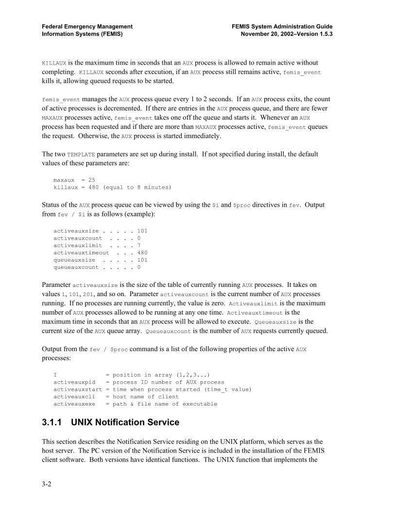
Federal Emergency Management FEMIS System Administration Guide Information Systems (FEMIS) November 20, 2002–Version 1.5.3
KILLAUX is the maximum time in seconds that an AUX process is allowed to remain active without completing. KILLAUX seconds after execution, if an AUX process still remains active, femis_event kills it, allowing queued requests to be started. femis_event manages the AUX process queue every 1 to 2 seconds. If an AUX process exits, the count of active processes is decremented. If there are entries in the AUX process queue, and there are fewer MAXAUX processes active, femis_event takes one off the queue and starts it. Whenever an AUX process has been requested and if there are more than MAXAUX processes active, femis_event queues the request. Otherwise, the AUX process is started immediately. The two TEMPLATE parameters are set up during install. If not specified during install, the default values of these parameters are:
maxaux = 25 killaux = 480 (equal to 8 minutes)
Status of the AUX process queue can be viewed by using the $i and $proc directives in fev. Output from fev / $i is as follows (example):
activeauxsize . . . . . 101 activeauxcount . . . . 0 activeauxlimit . . . . 7 activeauxtimeout . . . 480 queueauxsize . . . . . 101 queueauxcount . . . . . 0
Parameter activeauxsize is the size of the table of currently running AUX processes. It takes on values 1, 101, 201, and so on. Parameter activeauxcount is the current number of AUX processes running. If no processes are running currently, the value is zero. Activeauxlimit is the maximum number of AUX processes allowed to be running at any one time. Activeauxtimeout is the maximum time in seconds that an AUX process will be allowed to execute. Queueauxsize is the current size of the AUX queue array. Queueauxcount is the number of AUX requests currently queued. Output from the fev / $proc command is a list of the following properties of the active AUX processes:
I = position in array (1,2,3...) activeauxpid = process ID number of AUX process activeauxstart = time when process started (time_t value) activeauxcli = host name of client activeauxexe = path & file name of executable
3.1.1 UNIX Notification Service This section describes the Notification Service residing on the UNIX platform, which serves as the host server. The PC version of the Notification Service is included in the installation of the FEMIS client software. Both versions have identical functions. The UNIX function that implements the
3-2
Federal Emergency Management FEMIS System Administration Guide Information Systems (FEMIS) November 20, 2002–Version 1.5.3
Notification Service is called femis_event. The purpose of femis_event is to provide PC users of the FEMIS event notification system a communication path for the sharing of event information with each other. Events posted at one PC are sent to other PCs on the network by communicating with one or more notification servers. Local events posted at one PC client workstation are received at the notification server running on the LAN and then sent out to all clients that have expressed an interest in that event. Global events posted at one PC client workstation are received at the notification server running on the LAN and then sent out to clients on that LAN and also to other notification servers on the WAN. The femis_event is normally run as a background daemon process. Scripts that are used to startup the FEMIS system also invoke the notification server. As do all sockets servers, femis_event utilizes a predefined service port on which to listen for client connection requests. By default, the service port is obtained from a definition in /etc/services, the standard UNIX data file of Internet services and aliases. The standard service name of the notification server is femis-notify. 3.1.1.1 Executable Binary Files Two executable binary files are in the UNIX notification subsystem.
/home/femis/bin/femis_event : notification server executable /home/femis/bin/fev : a client application for UNIX environment
3.1.1.2 Configuration Data File The notification server utilizes one configuration file.
/home/femis/etc/femis_event.conf : notification server configurations
3.1.1.3 Service Port Data File The three FEMIS network protocols multiplex on service port 1776. A definition of FEMIS 1776 must be present in the UNIX service ports data file (/etc/services). 3.1.1.4 Protocol Numbers The current FEMIS protocol numbers are identical to the legacy FEMIS service port numbers. Including the obsolete meteorological protocol, the names and numbers are as follows:
9015 femis-command command server daemon
9020-35 femis-notify notification service
9037 femis-metdata meteorological data daemon
9040 femis-monitor femis monitor daemon
3-3
Federal Emergency Management FEMIS System Administration Guide Information Systems (FEMIS) November 20, 2002–Version 1.5.3
In the event of service port or protocol number conflicts, contact PNNL immediately before attempting to reconfigure the IP port addresses, which must be performed before a correct installation of the FEMIS network daemons can be accomplished. 3.1.1.5 Daemon Server Startup Scripts should be used to start or restart the notification server daemon. The following script will successfully start and restart the command and notification servers:
# sh /etc/init.d/femis {start or stop}
To stop and start femis_event from command line, you should use the stopnotify and startnotify scripts in /home/femis/bin. The femis script in init.d is a specialized automated script and may cause adverse side effects if run manually from the command line. 3.1.2 Notification Server Configuration Options 3.1.2.1 Command-line Options The command-line options of program femis_event that are defined in this section are femis_event : executes in foreground femis_event -c : executes a clone in background
femis_event –H homedir : specifies path to FEMIS home directory femis_event -v : report the current version
femis_event -V : report the current + rcs versions femis_event -q : quiet mode femis_event -Q : really quiet mode femis_event -d : executes with many diagnostics femis_event -a : enable keep alive mode femis_event -q -d : executes with only a few diagnostics femis_event -L FFFF : write a verbose log file named FFFF femis_event -l FFFF : write a brief log file named FFFF femis_event -e FFFF : write an error only log file femis_event -s SSSS : specifies service name for getservbyname femis_event -S : uses service name femis-notify if found femis_event -p PPPP : gets port number from environment variable PPPf femis_event -t secs : RESERVED – NOT IMPLEMENTED (see note) femis_event -i : report primary ip address and port number femis_event nnnn : use port nnnn instead of standard femis_event host : connect to named server femis_event host host : connect to named servers (see note) femis_event -r : use registered service port (1776) femis_event –conf file : specify a configuration file path/name femis_event # host host : port number # and a list of hosts femis_event -u : use unregistered service port (9020-29)
3-4

Federal Emergency Management FEMIS System Administration Guide Information Systems (FEMIS) November 20, 2002–Version 1.5.3
Normally, only femis_event -c host will be needed to start executing a notification server. However, the additional options can be mixed to provide logging, diagnostics, and nonstandard service port usage. 3.1.2.2 Clone Process in Background Option When this option has been included anywhere on the command line, the femis_event program clones itself and then the parent exits, leaving the child process to carry on as a background daemon process. if (fork () != 0) exit (0); ....
Example: femis_event -c 3.1.2.3 Display Version Options Including -v or -V anywhere on the command line with femis_event, causes the current version or the current version with RCS version to be displayed. Example: % femis_event -v FEMIS_EVENT - Version 1.0.11 - Wed Dec 14 15:19:49 PST 1994 % femis_event -V FEMIS_EVENT - Version 1.0.11 - Wed Dec 14 15:19:49 PST 1994 Copyright © 1994 Battelle Memorial Institute. All Rights Reserved. RCS: $Id: femis_event.cc,v 1.2 1994/12/14 23:17:08 d31033 Exp d31033$
The femis_event version is the current code version, not the FEMIS nor the RCS version. The date and time indicate when the executable was compiled and linked. 3.1.2.4 Diagnostic and Quiet Modes Using -d causes diagnostics to be printed out when running in foreground mode, i.e., not using option -c. Including -q or -Q with -d limits the amount of diagnostic information printed out. Options -q and -Q mean quiet and real quiet respectively. Using -d alone produces verbose diagnostics. Using -d -q limits the diagnostics. Using -d -Q limits all but severe diagnostics. Examples: % femis_event -q : quiet mode % femis_event -Q : really quiet mode % femis_event -d : executes with many diagnostics % femis_event -q -d : executes with only a few diagnostics
3-5
Federal Emergency Management FEMIS System Administration Guide Information Systems (FEMIS) November 20, 2002–Version 1.5.3
3.1.2.5 Service Port Name Option Including this option lets you specify the service port name on the command line rather than using the default name, femis-notify. Example: % femis_event -c -s evtserv-test-3-eoc
For this command to work correctly, the service name evtserv-test-3-eoc must have been entered in the /etc/services data file. Using option -s causes the standard service port name to be invoked. 3.1.2.6 Service Port Environment Option This option lets you specify service ports in environment variables. Example: % setenv MY_FEV_PORT 9027 % femis_event -p MY_FEV_PORT -c
3.1.2.7 Display IP Address and Service Port When the notification server is started with the -i option, rather than starting up a Notification Service, it just reports status information about network addresses and then exits. Information displayed includes the date/time of the last build (version identification), name of the local host, primary IP address of the local host, and service port number for the client connections. Example: > su – femis Password: ******** > femis_event -i Last build ...……. Thu Oct 17 11:54:08 PDT 1996 Host name is ..…. fallout.pnl.gov IP address is ….. 130.20.92.118 Port number is … 9020 >
The purpose of this directive is to obtain information needed in the multiple IP address workaround. Also see Section 2.10.2 Setting Up femis_event, in the Installation Guide for FEMIS Version 1.5.3. 3.1.2.8 Enable Log Files These options let you enable log file output from femis_event. The -e option creates an errors-only log file. Option -l produces a brief diagnostic log file. Option -L generates a verbose log. Place the desired file name in the argument following -e, -l, or -L. Examples: % femis_event -e errors-only.log.12-24-94 -c % femis_event -L femis_event.log.12-25-94 -c -p XMAS_PORT % femis_event -l /home/femis/log/femis_event.log`date +%y%m%d.%H%M`
3-6
Federal Emergency Management FEMIS System Administration Guide Information Systems (FEMIS) November 20, 2002–Version 1.5.3
3.1.2.9 Nonstandard Port from Command Line The notification server can be started with a nonstandard service port without the need for changes in /etc/services (which requires root access) or changing the environment variables simply by including the desired port number on the command line (specify only once). Example: % femis_event -c 9920 % fev - 9920
3.1.2.10 Connecting to Other EOC’s Notification Server To have the notification servers at multiple EOCs connected together, include the names of the other EOC server hosts on the command line. Example: server1:% femis_event -c server2 server2:% femis_event -c server1
3.1.2.11 Multiple Remote EOC Servers Limitation For this release, no special server-to-server algorithms for routing have been implemented in the notification server. Smart routing algorithms may be implemented in a future version. Also, the -t option, a part of multi-host, is not implemented. If you specify only one remote host, you get the optimal routing, which is host-to-host with no alternate conditions or routes. If you specify two or more remote hosts, the local server connects with all the remote hosts you named. Global event messages are then relayed to all specified remote hosts, even though that may not be necessary. As a result, global messages may be sent to a remote host more than once. 3.1.2.12 Server to Server Connection The FEMIS UNIX notification server (femis_event) supports a network of multiple notification servers. Any number of server programs can interconnect with each other, and the purpose of this interconnection is to provide a medium for communicating global event messages, provided that topology of the network is not a concern. To establish connection to other servers, a list of notification servers can be included on the command line. The syntax to designate a notification server connection is as follows: host name (uses default service port)
In the following lines, all servers use the same default service port number. Example: %femis_event -c countyeoc stateeoc %femis_event -c irzcountyeoc pazcountyeoc stateeoc
3-7

Federal Emergency Management FEMIS System Administration Guide Information Systems (FEMIS) November 20, 2002–Version 1.5.3
Multiple notification servers can be executed on the same host by using a different service port number for each instance. The syntax to designate multiple notification server connections is as follows:
%<port number>@<host name> port-and-host using registered service port %<port number>#<host name> port-and-host using unregistered service port
At the current time, only the registered service port method is being utilized by FEMIS systems fielded by CSEPP. In the following lines, two notification servers are started and each is cross connected to the other. Example: %thiseoc:/home/femis/exe/% femis_event -c 9021 9022@thiseoc %thiseoc:/home/femis/exe/% femis_event -c 9022 9021@thiseoc
In the above example, unregistered service ports 9021 and 9022 are used rather than the default service port 9020. Server 9021 is connected to server 9022, and server 9022 is connected to server 9021. These connections are on the same host. In the current FEMIS release, both concepts above have limitations. First, event routing is not optimized for more than two notification servers. Thus, a single event declaration will be sent multiple times on inter-network links. A network of notification servers can be started by implementing exact topology in a series of startup commands. Example: posteoc% femis_event -c 9020 9020@countyeoc 9020@stateeoc stateeoc% femis_event -c 9020 9020@posteoc 9020@countyeoc
countyeoc% femis_event -c 9020 9020@posteoc 9020@stateeoc
The above example starts notification servers on three hosts: posteoc, countyeoc, and stateeoc. Each is capable of sending global event messages to the other two. No regard is given to topology, i.e., each server sends events to the other two servers, even if having one of the others do a relay would accommodate more efficient use of network bandwidth. An alternate way to start the servers is to start one, then add one to the network, and later add the third. Example: posteoc% femis_event -c 9020
The above established a single notification server. Next enter: countyeoc% femis_event -c 9020 9020@posteoc
3-8
Federal Emergency Management FEMIS System Administration Guide Information Systems (FEMIS) November 20, 2002–Version 1.5.3
Now there is a two-node event server network: countyeoc connects to posteoc, which learns of the new server–to–server connection. Next enter: stateeoc% femis_event -c 9020 9020@posteoc 9020@countyeoc
We now have a three-node event server network. Stateeoc connects to both posteoc and countyeoc and each learn of the new server node. Graceful removal of nodes from the notification server topology and optimization of topology for saving network bandwidth have not yet been implemented. These will be done in future FEMIS releases. 3.1.2.13 Which Service Port to Use Which service port the notification server uses is determined as follows: from the following list, the first service port that produces a valid service port number is used as the service port method for this daemon server. • If the port number is included on the command line, then that port is used even if the methods
below also produce a valid service port number. Example: femis_event 9975
• If a service name is included on the command line (via -s or -S), then that service name is used
in a getservbyname() call. If that service name returns a valid service port from the /etc/services data file, then that port is used. Example:
femis_event -s FEMIS_ShellServer
• If an environment name is included on the command line, then that environment name is
translated into a service port number. Example: setenv MYPORT 7120 ; femis_event -p MYPORT
• The default service name, femis-notify, is tried in a call to getservbyname(). If that returns a
valid service port, then that port number is used. • The default environment name FEMIS_EVENT_PORT is translated. If that name is defined and
translates to a valid port number, then that service port is used. • If all the above fail, femis_event terminates with an error.
3-9
Federal Emergency Management FEMIS System Administration Guide Information Systems (FEMIS) November 20, 2002–Version 1.5.3
Normally, you can just use the standard service port number from the /etc/services file. However, for testing and diagnostics, additional methods have been included for running additional notification server modules that use a nonstandard port number, so there is no interference with normal operations. 3.1.2.14 Enable Keep Alive If the UNIX notification server is started with -a specified, keep alive mode for all socket calls is utilized. 3.1.2.15 Registered and Unregistered Service Port Command line option -r specifies use of the registered service port only. Command line option -u specifies use of the unregistered service ports only. The default starting is the registered service port. Previously the default was to unregistered ports. For more information, see Section 6.0, FEMIS Contact Daemon. Whether the femis_event was executed using –r (registered and default) or –u (unregistered) method, both methods are able to cross connect with other femis_event/s that can be of either type. However, the startnotify script must know which method to utilize. For registered, use PORT@HOST. For unregistered, use PORT#HOST. 3.1.3 femis_event EVENT Configuration File The femis_event uses a configuration file. The default femis_event configuration file is located at /home/femis/etc/femis_event.conf. This configuration file contains set up information and details of command line options for auxiliary processes, e.g., Data Driven Notification (DDN) and Data Exchange Interface (DEI) scripts. Auxiliary femis_event processes are utilized by the FEMIS DDN and DEI scripts. DDN processes are Perl scripts. See Section 7.0, FEMIS Data Exchange Interface (DEI), for more information on DEI. To specify a femis_event configuration file path/name other than the default, use the -conf <file> command line option to femis_event. The configuration file is a plain text file. Parsing rules are as follows: • Any line starting with a # is a comment line. • The line com port=registered specifies the registered service port to be used when no
command line option is specified. Command line options –r and –u override this command.
3-10

Federal Emergency Management FEMIS System Administration Guide Information Systems (FEMIS) November 20, 2002–Version 1.5.3
• The line com port=unregistered specifies the unregistered service port to be used when no command line option is specified. Command line options –r and –u override this command.
• The line com fevpath=femisbin specifies to look in /home/femis/bin for the fev executable. • The line com fevpath=dotslash specifies to look in ./ for the fev executable. • A line starting with aux specifies information pertaining to the launching of auxiliary processes. • aux argname=on turns argument naming on. In this mode, arguments to the auxiliary process
are passed as -<name> <value>. If aux argname=off is specified, arguments are passed just as <value> with no argument naming utilized. Naming allows for free format argument lists.
• aux keypos=ITEM specifies the position of which item to key on. Possible ITEMs are msgname,
exerid, auxprocessident, and parm#. The Keypos option specifies which message field becomes the key field for selection of an auxiliary process to be launched.
• aux ifport=PORT specifies only launch this command if the notification server’s port/protocol is
equal to PORT. PORT is a decimal number value. If this option is not specified, the command is always launched. If the option is present and PORT is not the port/protocol, the command will not be launched.
• aux notport=PORT specifies only launch this command if the notification server’s port/protocol
is not equal to PORT. PORT is a decimal number value. If this option is not specified, the command is always launched. If the option is present and PORT is equal to the port/protocol, the command will be launched.
• aux exe=path/file specifies the path/file name of the auxiliary process executable file. The
file must be tagged as X (executable) in the file system. The executable file can be a compiled/linked program, a shell script, a Perl script, or any executable.
• aux key=VALUE specifies what value the key field must be equal to in order to select and launch
this command. • aux arg=ITEM specifies an item to include in the argument list to the auxiliary process. The
possible ITEM names are msgname, exerid, auxprocessid, parm#, origin, msgflags, message, home, host, port, stdport, and fev.
All ITEMs are extracted from the <…message…>. ITEMs are as follows: MsgName is message name. ExerID is the exercise identification. AuxProcessID is the auxiliary process identification. Parm# is parameter number. Origin is the complete origin string from the originating PC notification code. MsgFlags is the message flags, bit encoded. Message is the full and complete message string. Home is the femis_event home directory, e.g., /files13/home/femis. Host is the server’s host name. Port is the port/protocol number, e.g., 9020. StdPort is Yes or No depending on whether standard
3-11
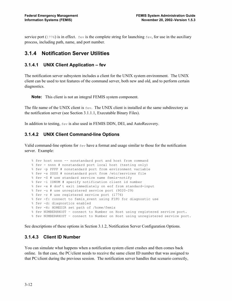
Federal Emergency Management FEMIS System Administration Guide Information Systems (FEMIS) November 20, 2002–Version 1.5.3
service port (1776) is in effect. fev is the complete string for launching fev, for use in the auxiliary process, including path, name, and port number. 3.1.4 Notification Server Utilities 3.1.4.1 UNIX Client Application – fev The notification server subsystem includes a client for the UNIX system environment. The UNIX client can be used to test features of the command server, both new and old, and to perform certain diagnostics.
Note: This client is not an integral FEMIS system component. The file name of the UNIX client is fev. The UNIX client is installed at the same subdirectory as the notification server (see Section 3.1.1.1, Executable Binary Files). In addition to testing, fev is also used in FEMIS DDN, DEI, and AutoRecovery. 3.1.4.2 UNIX Client Command-line Options Valid command-line options for fev have a format and usage similar to those for the notification server. Example: % fev host nnnn -- nonstandard port and host from command % fev - nnnn # nonstandard port local host (testing only) % fev -p PPPP # nonstandard port from environment variable % fev -s SSSS # nonstandard port from /etc/services file % fev -S # use standard service name femis-notify % fev -i IDNUM # specify notification client id number % fev -x # don’t exit immediately on eof from standard-input % fev -u # use unregistered service port (9020-29)
% fev -r # use registered service port (1776) % fev -f: connect to femis_event using FIFO for diagnostic use % fev -d: diagnostics enabled % fev -H: HOMEDIR set path of /home/femis
% fev NUMBER@HOST – connect to Number on Host using registered service port. % fev NUMBER#HOST – connect to Number on Host using unregistered service port.
See descriptions of these options in Section 3.1.2, Notification Server Configuration Options. 3.1.4.3 Client ID Number You can simulate what happens when a notification system client crashes and then comes back online. In that case, the PC/client needs to receive the same client ID number that was assigned to that PC/client during the previous session. The notification server handles that scenario correctly,
3-12
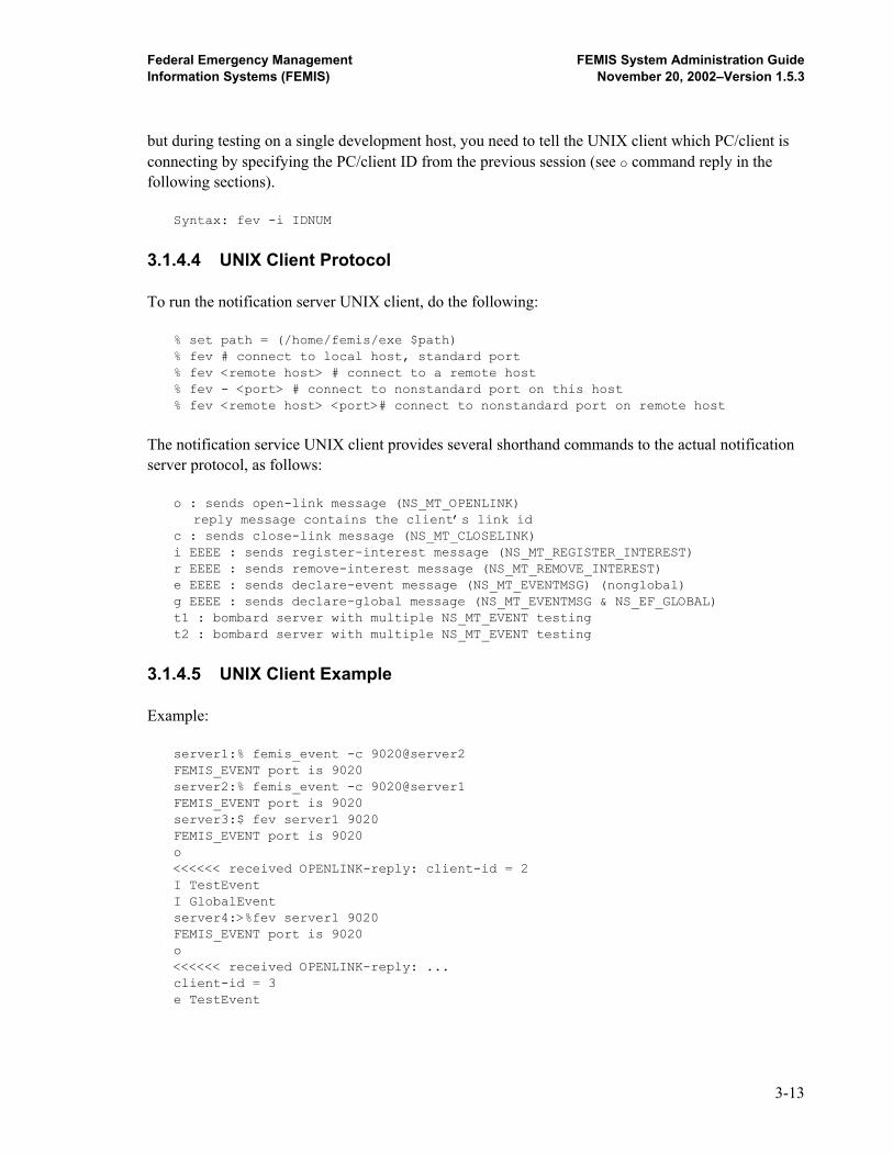
Federal Emergency Management FEMIS System Administration Guide Information Systems (FEMIS) November 20, 2002–Version 1.5.3
but during testing on a single development host, you need to tell the UNIX client which PC/client is connecting by specifying the PC/client ID from the previous session (see o command reply in the following sections). Syntax: fev -i IDNUM
3.1.4.4 UNIX Client Protocol To run the notification server UNIX client, do the following: % set path = (/home/femis/exe $path) % fev # connect to local host, standard port % fev <remote host> # connect to a remote host % fev - <port> # connect to nonstandard port on this host % fev <remote host> <port># connect to nonstandard port on remote host
The notification service UNIX client provides several shorthand commands to the actual notification server protocol, as follows: o : sends open-link message (NS_MT_OPENLINK) reply message contains the client’s link id c : sends close-link message (NS_MT_CLOSELINK) i EEEE : sends register-interest message (NS_MT_REGISTER_INTEREST) r EEEE : sends remove-interest message (NS_MT_REMOVE_INTEREST) e EEEE : sends declare-event message (NS_MT_EVENTMSG) (nonglobal) g EEEE : sends declare-global message (NS_MT_EVENTMSG & NS_EF_GLOBAL) t1 : bombard server with multiple NS_MT_EVENT testing t2 : bombard server with multiple NS_MT_EVENT testing
3.1.4.5 UNIX Client Example Example: server1:% femis_event -c 9020@server2 FEMIS_EVENT port is 9020 server2:% femis_event -c 9020@server1 FEMIS_EVENT port is 9020 server3:$ fev server1 9020 FEMIS_EVENT port is 9020 o <<<<<< received OPENLINK-reply: client-id = 2 I TestEvent I GlobalEvent server4:>%fev server1 9020 FEMIS_EVENT port is 9020 o <<<<<< received OPENLINK-reply: ... client-id = 3 e TestEvent
3-13
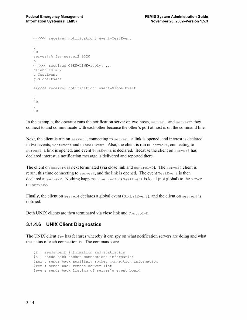
Federal Emergency Management FEMIS System Administration Guide Information Systems (FEMIS) November 20, 2002–Version 1.5.3
<<<<<< received notification: event=TestEvent c ^D server4:% fev server2 9020 o <<<<<< received OPEN-LINK-reply: ... client-id = 2 e TestEvent g GlobalEvent <<<<<< received notification: event=GlobalEvent c ^D c ^D
In the example, the operator runs the notification server on two hosts, server1 and server2; they connect to and communicate with each other because the other’s port at host is on the command line. Next, the client is run on server3, connecting to server1, a link is opened, and interest is declared in two events, TestEvent and GlobalEvent. Also, the client is run on server4, connecting to server1, a link is opened, and event TestEvent is declared. Because the client on server3 has declared interest, a notification message is delivered and reported there. The client on server4 is next terminated (via close link and control-D). The server4 client is rerun, this time connecting to server2, and the link is opened. The event TestEvent is then declared at server2. Nothing happens at server3, as TestEvent is local (not global) to the server on server2. Finally, the client on server4 declares a global event (GlobalEvent), and the client on server3 is notified. Both UNIX clients are then terminated via close link and Control-D. 3.1.4.6 UNIX Client Diagnostics The UNIX client fev has features whereby it can spy on what notification servers are doing and what the status of each connection is. The commands are $i : sends back information and statistics $s : sends back socket connections information $aux : sends back auxiliary socket connection information $rem : sends back remote server list $eve : sends back listing of server’s event board
3-14
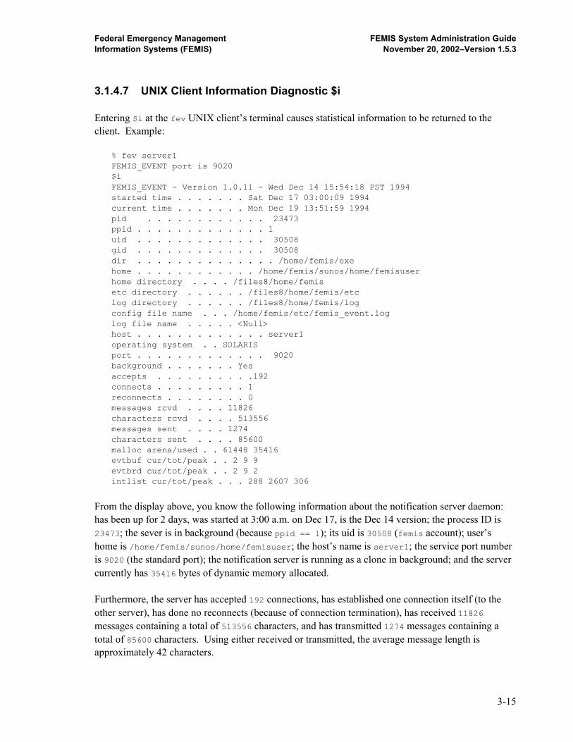
Federal Emergency Management FEMIS System Administration Guide Information Systems (FEMIS) November 20, 2002–Version 1.5.3
3.1.4.7 UNIX Client Information Diagnostic $i Entering $i at the fev UNIX client’s terminal causes statistical information to be returned to the client. Example:
% fev server1 FEMIS_EVENT port is 9020 $i FEMIS_EVENT - Version 1.0.11 - Wed Dec 14 15:54:18 PST 1994 started time . . . . . . . Sat Dec 17 03:00:09 1994 current time . . . . . . . Mon Dec 19 13:51:59 1994 pid . . . . . . . . . . . . 23473 ppid . . . . . . . . . . . . . 1 uid . . . . . . . . . . . . . 30508 gid . . . . . . . . . . . . . 30508 dir . . . . . . . . . . . . . . /home/femis/exe home . . . . . . . . . . . . /home/femis/sunos/home/femisuser home directory . . . . /files8/home/femis etc directory . . . . . . /files8/home/femis/etc log directory . . . . . . /files8/home/femis/log config file name . . . /home/femis/etc/femis_event.log log file name . . . . . <Null> host . . . . . . . . . . . . . server1 operating system . . SOLARIS port . . . . . . . . . . . . . 9020 background . . . . . . . Yes accepts . . . . . . . . . .192 connects . . . . . . . . . 1 reconnects . . . . . . . . 0 messages rcvd . . . . 11826 characters rcvd . . . . 513556 messages sent . . . . 1274 characters sent . . . . 85600 malloc arena/used . . 61448 35416 evtbuf cur/tot/peak . . 2 9 9 evtbrd cur/tot/peak . . 2 9 2 intlist cur/tot/peak . . . 288 2607 306
From the display above, you know the following information about the notification server daemon: has been up for 2 days, was started at 3:00 a.m. on Dec 17, is the Dec 14 version; the process ID is 23473; the sever is in background (because ppid == 1); its uid is 30508 (femis account); user’s home is /home/femis/sunos/home/femisuser; the host’s name is server1; the service port number is 9020 (the standard port); the notification server is running as a clone in background; and the server currently has 35416 bytes of dynamic memory allocated. Furthermore, the server has accepted 192 connections, has established one connection itself (to the other server), has done no reconnects (because of connection termination), has received 11826 messages containing a total of 513556 characters, and has transmitted 1274 messages containing a total of 85600 characters. Using either received or transmitted, the average message length is approximately 42 characters.
3-15
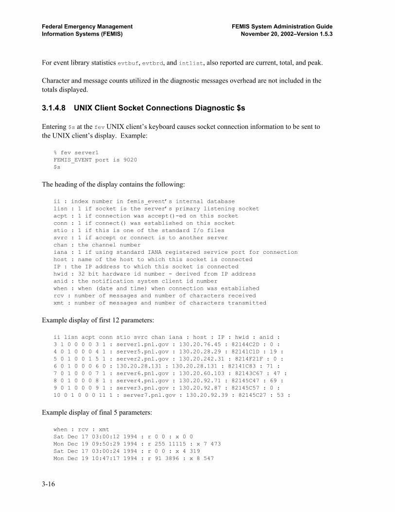
Federal Emergency Management FEMIS System Administration Guide Information Systems (FEMIS) November 20, 2002–Version 1.5.3
For event library statistics evtbuf, evtbrd, and intlist, also reported are current, total, and peak. Character and message counts utilized in the diagnostic messages overhead are not included in the totals displayed. 3.1.4.8 UNIX Client Socket Connections Diagnostic $s Entering $s at the fev UNIX client’s keyboard causes socket connection information to be sent to the UNIX client’s display. Example: % fev server1 FEMIS_EVENT port is 9020 $s
The heading of the display contains the following:
ii : index number in femis_event’s internal database lisn : 1 if socket is the server’s primary listening socket acpt : 1 if connection was accept()-ed on this socket conn : 1 if connect() was established on this socket stio : 1 if this is one of the standard I/o files svrc : 1 if accept or connect is to another server chan : the channel number iana : 1 if using standard IANA registered service port for connection host : name of the host to which this socket is connected IP : the IP address to which this socket is connected hwid : 32 bit hardware id number - derived from IP address anid : the notification system client id number when : when (date and time) when connection was established rcv : number of messages and number of characters received xmt : number of messages and number of characters transmitted
Example display of first 12 parameters: ii lisn acpt conn stio svrc chan iana : host : IP : hwid : anid : 3 1 0 0 0 0 3 1 : server1.pnl.gov : 130.20.76.45 : 82144C2D : 0 : 4 0 1 0 0 0 4 1 : server5.pnl.gov : 130.20.28.29 : 82141C1D : 19 : 5 0 1 0 0 1 5 1 : server2.pnl.gov : 130.20.242.31 : 8214F21F : 0 : 6 0 1 0 0 0 6 0 : 130.20.28.131 : 130.20.28.131 : 82141C83 : 71 : 7 0 1 0 0 0 7 1 : server6.pnl.gov : 130.20.60.103 : 82143C67 : 47 : 8 0 1 0 0 0 8 1 : server4.pnl.gov : 130.20.92.71 : 82145C47 : 69 : 9 0 1 0 0 0 9 1 : server3.pnl.gov : 130.20.92.87 : 82145C57 : 0 : 10 0 1 0 0 0 11 1 : server7.pnl.gov : 130.20.92.39 : 82145C27 : 53 :
Example display of final 5 parameters: when : rcv : xmt Sat Dec 17 03:00:12 1994 : r 0 0 : x 0 0 Mon Dec 19 09:50:29 1994 : r 255 11115 : x 7 473 Sat Dec 17 03:00:24 1994 : r 0 0 : x 4 319 Mon Dec 19 10:47:17 1994 : r 91 3896 : x 8 547
3-16

Federal Emergency Management FEMIS System Administration Guide Information Systems (FEMIS) November 20, 2002–Version 1.5.3
Mon Dec 19 10:27:49 1994 : r 259 11303 : x 8 547 Mon Dec 19 10:45:24 1994 : r 56 2335 : x 2 117 Mon Dec 19 11:14:17 1994 : r 13 13 : x 0 0 Mon Dec 19 10:29:36 1994 : r 56 2335 : x 2 117
From the above display, we can say that five clients currently have active connections, that client ID numbers range from 19 to 71, and that one client has no entry in the local name table (IP address 130.20.28.131). Socket 3 is the listening socket. Socket 5 connects to the notification server on server2. Socket 9 is the client doing diagnostics. Character and message counts utilized in the diagnostic messages are not included in the totals displayed. 3.1.4.9 UNIX Client Auxiliary Connect Information Diagnostic $aux Entering $aux at the fev UNIX client keyboard causes the auxiliary connect information to be sent to the UNIX client’s display. Example: % fev server1 FEMIS_EVENT port is 9020 $aux
The heading of the display that follows contains ii : index number in femis_event’s internal database conn : connect mode = L C A svrc : server circuit = 0 1 auxtype: aux connection type S C U host : name of host to which this socket is connected hwid : 32 bit hardware id number - derived from IP address port : port number of server/client at remote end pid : process id number of server/client process at remote end cid : client id number of server/client process at remote end
Example listing: 5 L 0 : U : virus.pnl.gov : 8214F20A : 9020 : 14415 : 0 6 C 1 : S : locusts.pnl.gov : 8214F20B : 9020 : 12093 : 0 7 A 0 : U : : 0 : 0 : 0 : 46 8 C 1 : S : temblor.pnl.gov : 8214F20C : 9020 : 19831 : 0 9 A 0 : U : : 0 : 0 : 0 : 38 10 A 0 : U : : 0 : 0 : 0 : 48 11 A 0 : U : : 0 : 0 : 0 : 43 12 A 0 : C : hattrick : 82145C57 : 9020 : 2593 : 0
3-17
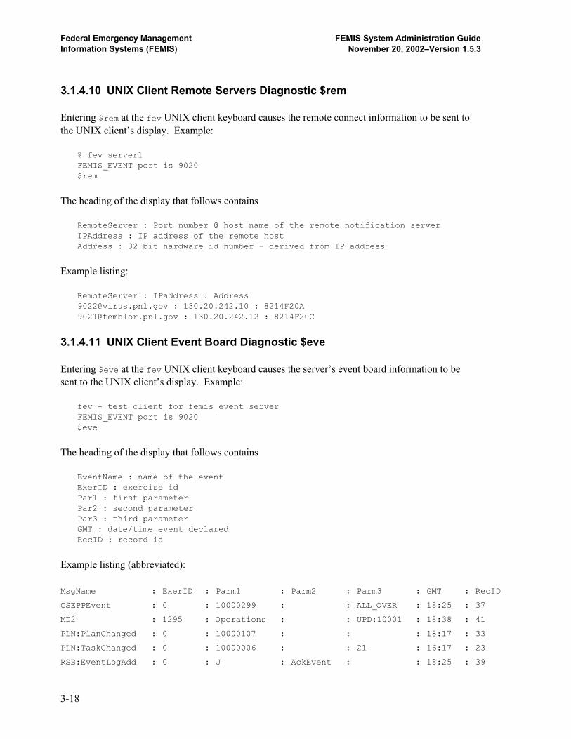
Federal Emergency Management FEMIS System Administration Guide Information Systems (FEMIS) November 20, 2002–Version 1.5.3
3.1.4.10 UNIX Client Remote Servers Diagnostic $rem Entering $rem at the fev UNIX client keyboard causes the remote connect information to be sent to the UNIX client’s display. Example: % fev server1 FEMIS_EVENT port is 9020 $rem
The heading of the display that follows contains RemoteServer : Port number @ host name of the remote notification server IPAddress : IP address of the remote host Address : 32 bit hardware id number - derived from IP address
Example listing: RemoteServer : IPaddress : Address [email protected] : 130.20.242.10 : 8214F20A [email protected] : 130.20.242.12 : 8214F20C
3.1.4.11 UNIX Client Event Board Diagnostic $eve Entering $eve at the fev UNIX client keyboard causes the server’s event board information to be sent to the UNIX client’s display. Example: fev - test client for femis_event server FEMIS_EVENT port is 9020 $eve
The heading of the display that follows contains EventName : name of the event ExerID : exercise id Par1 : first parameter Par2 : second parameter Par3 : third parameter GMT : date/time event declared RecID : record id
Example listing (abbreviated): MsgName : ExerID : Parm1 : Parm2 : Parm3 : GMT : RecID
CSEPPEvent : 0 : 10000299 : : ALL_OVER : 18:25 : 37
MD2 : 1295 : Operations : : UPD:10001 : 18:38 : 41
PLN:PlanChanged : 0 : 10000107 : : : 18:17 : 33
PLN:TaskChanged : 0 : 10000006 : : 21 : 16:17 : 23
RSB:EventLogAdd : 0 : J : AckEvent : : 18:25 : 39
3-18

Federal Emergency Management FEMIS System Administration Guide Information Systems (FEMIS) November 20, 2002–Version 1.5.3
RSB:EventLogAdd : 1295 : J : D2:10001 : : 18:37 : 40
Udept : 0 : : : : 15:19 : 19
Ufacility : 0 : : : : 15:16 : 18
UlocalID : 0 : TEADTEAD : alstuff : : 15:48 : 43
3.1.4.12 UNIX Client Synchronize Action $sync Entering $sync and a qualifier at the fev client keyboard causes the server to send the same message back to fev, which can utilize reception of known $sync messages to synchronize certain events and actions. The UNIX client uses the command $sync exit to synchronize forced exit while running in script mode, which must be used in conjunction with the -x option. Example script: #!/bin/csh -f # fev -x virus 9020<<eod o g My-Event 1 “par one” par_two par3 g My-Event 123 ““ - 999.000 g Your-Event 99 - - - c \$sync exit eod
The above script runs fev, opens a link, declares the three events, closes the link, and synchronizes a forced exit. 3.1.4.13 Data Driven Notification Command Line Arguments A Data Driven Notification (DDN) command line interface has been added to fev. This feature now allows a single event including DDN parameters to be constructed and sent by fev, based solely on new command line arguments. The presence of DDN command line arguments signals fev to utilize single event mode, instead of entering interactive mode. The following are DDN command line arguments for fev:
Argument Function -global This is a global event -nopost Do not post this event -aux Launch an auxiliary process -host HOST Name of host to receive this event
3-19
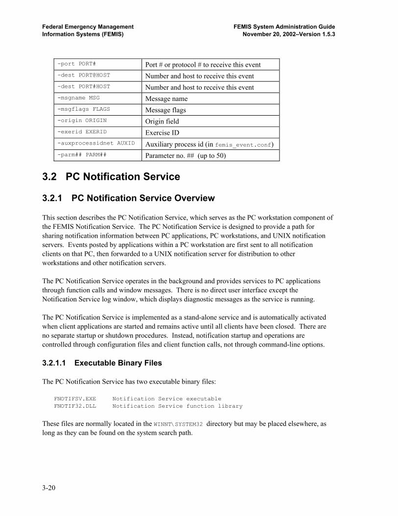
Federal Emergency Management FEMIS System Administration Guide Information Systems (FEMIS) November 20, 2002–Version 1.5.3
-port PORT# Port # or protocol # to receive this event -dest PORT@HOST Number and host to receive this event -dest PORT#HOST Number and host to receive this event -msgname MSG Message name -msgflags FLAGS Message flags -origin ORIGIN Origin field -exerid EXERID Exercise ID -auxprocessidnet AUXID Auxiliary process id (in femis_event.conf) -parm## PARM## Parameter no. ## (up to 50)
3.2 PC Notification Service 3.2.1 PC Notification Service Overview This section describes the PC Notification Service, which serves as the PC workstation component of the FEMIS Notification Service. The PC Notification Service is designed to provide a path for sharing notification information between PC applications, PC workstations, and UNIX notification servers. Events posted by applications within a PC workstation are first sent to all notification clients on that PC, then forwarded to a UNIX notification server for distribution to other workstations and other notification servers. The PC Notification Service operates in the background and provides services to PC applications through function calls and window messages. There is no direct user interface except the Notification Service log window, which displays diagnostic messages as the service is running. The PC Notification Service is implemented as a stand-alone service and is automatically activated when client applications are started and remains active until all clients have been closed. There are no separate startup or shutdown procedures. Instead, notification startup and operations are controlled through configuration files and client function calls, not through command-line options. 3.2.1.1 Executable Binary Files The PC Notification Service has two executable binary files: FNOTIFSV.EXE Notification Service executable FNOTIF32.DLL Notification Service function library
These files are normally located in the WINNT\SYSTEM32 directory but may be placed elsewhere, as long as they can be found on the system search path.
3-20

Federal Emergency Management FEMIS System Administration Guide Information Systems (FEMIS) November 20, 2002–Version 1.5.3
3.2.1.2 Notification Service Startup Since the Notification Service is started by the Notification Service DLL, the user has no control over startup operations. Instead, startup parameters are read from a configuration file and can be adjusted to suit the needs of a particular installation. 3.2.2 PC Notification Service Configuration Options The PC Notification Service can be customized by modifying one or more configuration parameters. These parameters allow you to change Notification Service behavior to accommodate client needs and special requirements. For instance, a remote user connected via a modem may need to increase the timeout limit for notification server connections, or a stand-alone installation might want to disable all network monitoring. Each of these requirements can be satisfied by adjusting the configuration parameters to fit the client’s needs. 3.2.2.1 Configuration Parameters Each configuration parameter has a unique name and most have a default value. The available configuration parameters are as follows:
Parameter Purpose Default Value RunAsStandAlone StandAlone flag (True/False) False SocketMaxWait Socket timeout value (seconds) 10 LostConnCheckInterval Lost connection check (seconds) 30 LostConnRetryInterval Lost connection retry (seconds) 30 EventQueueSweepInterval Queue sweep interval (seconds) 1 DefaultNotifServerHost Default server host name none DefaultNotifServerPort Default server port none
If the default value for a parameter is not satisfactory, you can assign a more suitable value. However, you must be careful that the new value is reasonable and does not have an adverse effect on Notification Service operation. 3.2.2.2 Notification Service Configuration File Notification Service configuration parameters are specified in a configuration file, FEMIS.INI, usually located in the Windows home directory. Each configuration parameter is specified by a key and its associated value, grouped under the [Notification Service] section.
3-21
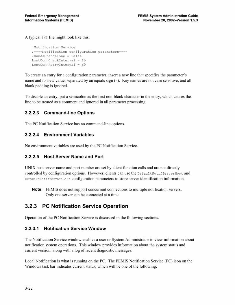
Federal Emergency Management FEMIS System Administration Guide Information Systems (FEMIS) November 20, 2002–Version 1.5.3
A typical INI file might look like this: [Notification Service] ;----Notification configuration parameters---- ;RunAsStandAlone = False LostConnCheckInterval = 10 LostConnRetryInterval = 60
To create an entry for a configuration parameter, insert a new line that specifies the parameter’s name and its new value, separated by an equals sign (=). Key names are not case sensitive, and all blank padding is ignored. To disable an entry, put a semicolon as the first non-blank character in the entry, which causes the line to be treated as a comment and ignored in all parameter processing. 3.2.2.3 Command-line Options The PC Notification Service has no command-line options. 3.2.2.4 Environment Variables No environment variables are used by the PC Notification Service. 3.2.2.5 Host Server Name and Port UNIX host server name and port number are set by client function calls and are not directly controlled by configuration options. However, clients can use the DefaultNotifServerHost and DefaultNotifServerPort configuration parameters to store server identification information.
Note: FEMIS does not support concurrent connections to multiple notification servers. Only one server can be connected at a time.
3.2.3 PC Notification Service Operation Operation of the PC Notification Service is discussed in the following sections. 3.2.3.1 Notification Service Window The Notification Service window enables a user or System Administrator to view information about notification system operations. This window provides information about the system status and current version, along with a log of recent diagnostic messages. Local Notification is what is running on the PC. The FEMIS Notification Service (PC) icon on the Windows task bar indicates current status, which will be one of the following:
3-22

Federal Emergency Management FEMIS System Administration Guide Information Systems (FEMIS) November 20, 2002–Version 1.5.3
Stand-alone - blue icon with green border Connected to server - blue icon with black border Lost connection - blue icon with red border and a red slash across it
Note: If the icon is blue, has a red border, and does not have a red slash across it, then no server has been selected and notification is not shared with other PCs.
The Notification server response time from your PC can be checked by completing the following steps: 1. Open the FEMIS Notification Service (PC) window. 2. Select Status Server Response Time. If you are connected to a server, a popup message
box will display the current response time. If the connection is very slow, it may take up to 30 seconds to determine the response time. The message window automatically closes itself after one minute. The Notification Status window (Figure 3.1) displays information about local and server status, client count, event count, server host name, and server port number. The Notification Status window updates itself automatically.
Figure 3.1. FEMIS Notification Service Window
For version information, select Help About on the FEMIS Workbench. The About window will display, which contains version and copyright information. For diagnostic information, consult the main Notification Service window. This window displays recent diagnostic and error messages, including network messages to and from the server and attempts to restore lost server connections.
3-23
Federal Emergency Management FEMIS System Administration Guide Information Systems (FEMIS) November 20, 2002–Version 1.5.3
3.2.3.2 Lost Connections Lost connections with the UNIX notification server are a common problem and occur for a variety of reasons. The PC Notification Service is designed to automatically detect and restore lost connections, with minimal impact on FEMIS software operations. Whenever a lost server connection is detected, the PC Notification Service sends a diagnostic message to the log window, activates the Lost Connection icon, and goes into restoration mode. Every few seconds, as specified by the LostConnRetryInterval value, the Notification Service attempts to contact the server and restore the connection. During this time, local notification still occurs, but all messages to and from the server are lost and cannot be recovered. When the server finally answers, the connection is restored and the Notification Service returns to normal operation. As discussed in Section 3.2.3.1, Notification Service Window, you can use the status icon or status window to monitor lost connections. 3.2.4 PC Notification Test Client 3.2.4.1 PC Test Client – NOTITEST.EXE The PC Notification Test Client, NOTITEST.EXE, is included in the FEMIS installation and can be used to test notification functions and diagnose notification problems. This program enables a user to manually post notification events, monitor events generated by other applications, and force notification errors for testing purposes. See the Section 3.2.4.4, PC Test Client Functions, for more information. At startup (Figure 3.2), NOTITEST automatically establishes a notification client link and registers an interest in the Event1 : 1 event. It also enables notification loopback so it can receive its own events. However, NOTITEST starts in stand-alone mode, without connecting to a UNIX notification server. Use the OpenServerLink function if you wish to open a link to your notification server. 3.2.4.2 PC Test Client Configuration The PC Test Client has no configuration options or other means to customize its default behavior. However, the test functions (below) can be used to change client behavior at runtime. 3.2.4.3 PC Test Client Command-line Options The PC Test Client has no command-line options.
3-24
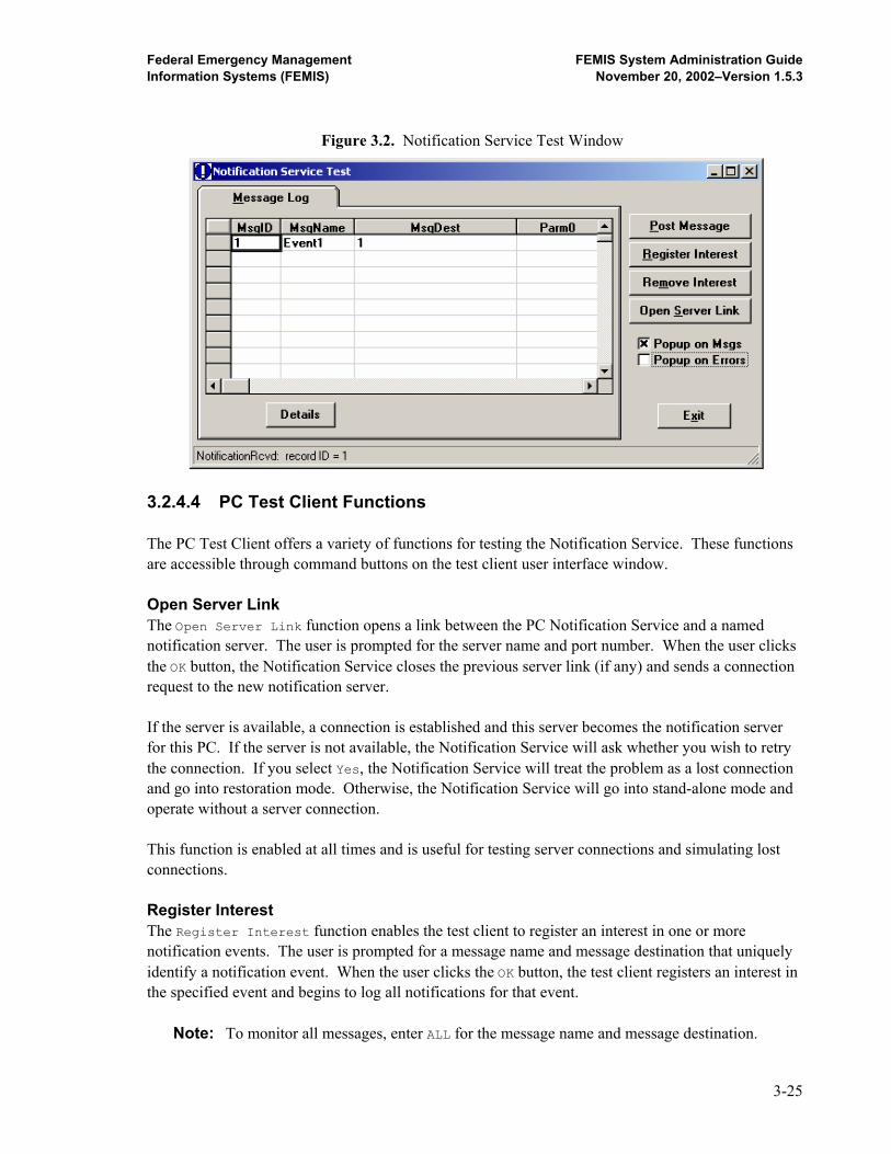
Federal Emergency Management FEMIS System Administration Guide Information Systems (FEMIS) November 20, 2002–Version 1.5.3
Figure 3.2. Notification Service Test Window
3.2.4.4 PC Test Client Functions The PC Test Client offers a variety of functions for testing the Notification Service. These functions are accessible through command buttons on the test client user interface window. Open Server Link The Open Server Link function opens a link between the PC Notification Service and a named notification server. The user is prompted for the server name and port number. When the user clicks the OK button, the Notification Service closes the previous server link (if any) and sends a connection request to the new notification server. If the server is available, a connection is established and this server becomes the notification server for this PC. If the server is not available, the Notification Service will ask whether you wish to retry the connection. If you select Yes, the Notification Service will treat the problem as a lost connection and go into restoration mode. Otherwise, the Notification Service will go into stand-alone mode and operate without a server connection. This function is enabled at all times and is useful for testing server connections and simulating lost connections. Register Interest The Register Interest function enables the test client to register an interest in one or more notification events. The user is prompted for a message name and message destination that uniquely identify a notification event. When the user clicks the OK button, the test client registers an interest in the specified event and begins to log all notifications for that event.
Note: To monitor all messages, enter ALL for the message name and message destination.
3-25

Federal Emergency Management FEMIS System Administration Guide Information Systems (FEMIS) November 20, 2002–Version 1.5.3
This function is very useful for troubleshooting notification problems because it allows the user to monitor notification events posted by other applications. For instance, if an application is not responding to a specific sequence of notification events, the test client program can register an interest in those events and verify that the events are being sent in the correct order. This function is enabled only when the test client has a valid client link. Remove Interest The Remove Interest function enables the test client to remove an interest in one or more notification events. The user is prompted for a message name and message destination that uniquely identify a notification event. When the user clicks the OK button, the test client removes its interest in the specified event and is no longer notified about that event. This function is enabled only when the test client has a valid client link. Post Event The Post Event enables the test client to post a notification event and simulate events posted by other applications. The user is prompted for the event name, exercise number, and three event parameters, along with control flags that determine how the event will be processed. When the user clicks the OK button, the test client sends this event to the Notification Service for distribution to other local and remote clients. This function is very useful for troubleshooting notification problems because it allows a user to simulate notification events posted by other applications. For instance, the test client can post a specific sequence of notification events and verify that other applications respond correctly to that sequence. This function is enabled at all times. Popup On Event The Popup On Event option is used to alert the user each time the test client receives an event notification. This allows the test client to function as an event monitor by displaying a popup message box whenever an event is received. This function can also test the Notification Service queuing functions by introducing a user-controlled delay into the event processing system. Popup On Errors The Popup On Errors option facilitates error-handling tests by displaying a popup message each time an invalid notification message is received. 3.2.4.5 PC Test Client Diagnostics The PC Test Client does not include any diagnostic functions.
3-26
Federal Emergency Management FEMIS System Administration Guide Information Systems (FEMIS) November 20, 2002–Version 1.5.3
3.2.5 Notification Server Troubleshooting The notification server is very stable; however, this program runs in a network environment and, thus, is prone to any and all failures that can occur in network computing and distributed data management systems. 3.2.5.1 Check Notification Server Active To check if the notification server is active, log in to the UNIX server and issue the following command: %/usr | ucb | ps axw | grep femis_event
If the notification server is active, you will get a reply such as: 17739 pe S 0:00 femis_event -c server1 -e femis_event.e.log.941219.1140
1073 pe S 0:00 grep femis_event
If the notification server is not active, only the second line above will be displayed. The process identification (PID) number of the femis_event notification server is the first number shown, e.g., 17739. 3.2.5.2 Check Notification Server Communication To check the notification server communication, run the UNIX test client either from the server host or from another UNIX system. You should be able to run fev and issue notification server instructions. Example: % fev
If the notification server is not active, you will get a reply such as the following and then be returned to the command-line processor: fev - test client for femis_event server FEMIS_EVENT port is 9020 connect failed: Connection refused %
If the notification server is active, you should get a reply such as the following: fev - test client for femis_event server FEMIS_EVENT port is 9020
After receiving the above reply, you can issue an instruction to the UNIX test client. Example: o
3-27
Federal Emergency Management FEMIS System Administration Guide Information Systems (FEMIS) November 20, 2002–Version 1.5.3
This is the test client’s command to open a link. Next you should see <<<<<< received OPENLINK-reply: client-id = nnnn
where nnnn is an open link ID number (could be any positive integer). If you get such a reply, the notification server is active and communicating. If the notification
server is active and communicating, then the problem is probably either in the network or on the PC side.
3.2.5.3 Aborting Notification Server If you need to abort the notification server during testing or troubleshooting, you must manually log in as the user account from which femis_event was started. In FEMIS, the user account is femis, or you can log in as superuser. You next need to learn the PID number of the femis_event server needing to be killed. There are two ways to learn the PID of a FEMIS server process. The first is to use the ps and grep commands. Example:
%/usr | ucb | ps axw | grep femis_event
If the notification server is active, you will get a reply such as:
23473 pe S 0:00 femis_event -c server2 -e femis_event.e.log.941219.1140 1073 pe S 0:00 grep femis_event
If the notification server is not active, only the second line above will be displayed. The PID of the femis_event notification server is the first number shown, e.g., 23473. The second way to learn the PID of femis_event is to run the test client and use the $i spy command. Example:
% fev - # connect to local host fev - test client for femis_event server FEMIS_EVENT port is 9020 $i pid . . . . . . . . . . 23473
From the $i reply, the femis_event pid is 23473. With the PID number, you can abort the notification server. The preferred way is
% kill -2 23473
3-28
Federal Emergency Management FEMIS System Administration Guide Information Systems (FEMIS) November 20, 2002–Version 1.5.3
Recheck if the server is still active. If the above kill -2 (the graceful exit), did not work, then use
% kill -9 23473
Using kill -9 will kill the notification server, but the state of open connections will be lost and possibly may not be recoverable until some long TCP/IP timeout period elapses. A script file, such as the following, may be used
foreach killnum ( -2 -9 )
ps ef >! ..PS..
set serverpid = ( `fgrep femis_event ..PS.. | awk `{print $2}’ ` ) foreach pid ( $serverpid ) echo kill $killnum $pid kill $killnum $pid end
end
3.2.5.4 Fixing Notification Port When running a FEMIS client application (such as a Visual Basic application), the application first uses the FEMIS.INI file in the Windows directory to get the notification server’s name and port number. If either the name or port number is incorrect, you will get an error 10054. You could fix the file to avoid this error occurring in the future; but it is not necessary because the Visual Basic application then lets you login to an EOC and gets a new notification server name and port number from the FEMIS database. If either the new name or port number is incorrect, you will get an error 10054. You must then correct the EOC table by changing the values for either the EOC_SERVER_NAME or the EOC_NOTIFY_PORT fields. 3.2.5.5 PC WinSock Errors The following list includes the errors encountered during development and testing of the notification server software. A complete list of WinSock and UNIX errors can be found in Windows Sockets, Version 1.1 documentation. PC WinSock Error 10022 This error is an internal Windows Sockets error which is caused when a Windows application crashes/terminates without properly closing down. In doing so, the Windows application has wasted and lost critical dynamic memory. Error 10022, which means invalid argument, is reported by mistake. The real problem is Windows running out of a critical resource. Shut down other Windows applications and reboot the PC.
3-29
Federal Emergency Management FEMIS System Administration Guide Information Systems (FEMIS) November 20, 2002–Version 1.5.3
PC WinSock Error 10024 This error is an internal Windows Sockets error which is caused when a Windows application crashes/terminates without properly closing down. In doing so, the Windows application has wasted and lost critical dynamic memory. Error 10024, which means too many files open, is reported by mistake. The real problem is Windows running out of a critical resource. Shut down other Windows applications and reboot the PC. PC WinSock Error 10038 This error is an internal Windows Sockets error that is caused by a software error, most likely manifested from Windows running out of a critical resource. In reaching this error, an application has tried to reuse an I/O channel that was previously connected to a network socket but has since been closed. Restart the affected applications. If this does not fix the problem, reboot the PC. PC WinSock Error 10050 This error means the network is down; there is no network communication with the server host to which this PC is trying to connect. Report the error to the System Administrator and wait for a diagnosis. After all hardware and communication bugs have been fixed, restart the affected applications. If this does not fix the problem, reboot the PC. PC WinSock Error 10053 This error means that connection to the server was aborted and may be because the server was terminated, either intentionally or by a failure. This error can also mean that connection was never established because the server is not currently active. Check if the notification server, femis_event is currently active on the UNIX server. If not, restart it using scripts described in Section 3.1.1.5, Daemon Server Startup. The UNIX test client can be used to check for server health, see Section 3.1.4, Notification Server Utilities. PC WinSock Error 10054 This error means that the notification server is not active. Check if the notification server, femis_event is currently active on the UNIX server. If not, restart it using scripts described in Section 3.1.1.5, Daemon Server Startup. The notification subsystem UNIX test client can be used to check on server health, see Section 3.1.4, Notification Server Utilities. This error can also mean that the client software on the PC does not have the correct service port number or server. The default port for the notification server is 9020. Client software must use this same service port. If the port number is determined to be incorrect, fix it and restart the client software applications. Reboot the PC if necessary.
3.3 Starting/Stopping Notification Service When the server is rebooted or shutdown, it runs the /etc/init.d/femis script, which start or stops the Notification Service using the following scripts in the /home/femis/bin directory.
3-30
Federal Emergency Management FEMIS System Administration Guide Information Systems (FEMIS) November 20, 2002–Version 1.5.3
3.3.1 Starting Notification Service The /home/femis/bin/start notify script uses the EOC List File (./etc/eoclist.dat) to determine how to start the Notification Service. The file tells how many Notification Service processes to start, which ports to use, and which other Notification Services to communicate with. You can run the following script.
% startnotify
If the Notification Service(s) is already running, you cannot start new ones. In other words, the startnotify command will only start the instances of femis_event that need to be started, and any that have already been started will simply exit from their duplicate copies. For example, assume that a particular server has five EOCs and five corresponding femis_event processes running. If you manually kill one of the processes and run startnotify again, startnotify will attempt to start five new copies of femis_event. For the four that are already running, you will receive a diagnostic message saying the process is already running. For the one that you manually killed, the startnotify script will start a new copy of femis_event. The startnotify script will also start the data driven notification manager (notifmgr.pl). This is a persistent process that services all data driven notifications. In addition, there is also an Oracle job responsible for processing data driven notifications. This process is started and monitored by AutoRecovery. If AutoRecovery does not see the process running, it calls PKG_DDN_MONITOR.P_START_MONITOR from SQLPLUS. The startnotify script has no control over this portion of the notification service. To start the Notification Service(s) with logging turned on, you can run the following script:
% startnotify -log
3.3.2 Stopping Notification Service The /home/femis/bin/stopnotify script stops the Notification Service(s) by finding all processes running the femis_event program and then kills them using kill -2. The stopnotify script will also stop the data driven notification manager (notifmgr.pl). This is a persistent process that services all data driven notifications. You can run the following script.
% stopnotify
3-31
Federal Emergency Management FEMIS System Administration Guide Information Systems (FEMIS) November 20, 2002–Version 1.5.3
3-32
3.4 Data Transfer Notification Data Transfer Notifications are used to acknowledge the receipt of data. Chemical Accident or Incident (CAI) notifications, Work Plans, D2PC cases, Threat Areas, Risk Areas and Protective Action Recommendations (PARs) are broadcast from onpost to offpost. The Data Transfer Notification sends data receipt acknowledgements from the offpost EOCs back to the onpost EOC. When the data has been sent, a Data Acknowledgement Notification window will be displayed on the sending PC. This window will update itself by looking for notifications sent by the receiving server. When the notification is received, a Data Acknowledgement record will also be written to the Shared Journal for historical reference. The FEMIS Notification Service will need to be started in order to run Data Transfer Notification. 3.4.1 Data Acknowledgement Notification Window When data is broadcast offpost or when a CAI is declared through FEMIS, the Data Acknowledgement Notification window will be displayed. As each server receives the data, a notification will be sent back to the originating server, and the window will be updated with the date and time the information was received. If the offpost server does not receive the data within approximately 6 minutes, the window will be updated with a Timed Out message.
Note: This window will never display Data Acknowledgements from EMIS. Use the Data Acknowledgement Monitoring window to receive EMIS Data Acknowledgements.
3.4.2 Data Acknowledgement Monitoring Window The Data Acknowledgement Monitoring window can be accessed from the Utility menu on the Workbench. It will display all the received Data Acknowledgements as they arrive. As each server receives the data, a notification will be sent back to the originating server, and the window will be updated with the date and time the information was received. If the offpost server does not receive the data within approximately 6 minutes, the window will be updated with a Timed Out message.
Note: This window will display Data Acknowledgements for data received from EMIS.
4.0 FEMIS Command Server Command server online documentation is provided in three man pages on the UNIX server. Log onto the EOC’s server as femis and enter: % man cmdservd % man cmdserv.conf % man cmdserv
cmdservd is the command server daemon. cmdserv.conf is the command server configuration file. cmdserv is a UNIX test client for the command server.
4.1 cmdservd – FEMIS Command Server Daemon 4.1.1 Synopsis cmdservd [-conf config-file] cmdservd [-conf config-file] [-v] [-syntax [-show] [-check]]
4.1.2 Availability The FEMIS command server daemon cmdservd executable, configuration file, test client, and related files are included with the FEMIS application. The default locations for these files are /home/femis/bin and /home/femis/etc on the FEMIS UNIX data server. 4.1.3 Description FEMIS utilizes remote command servers, executing on a UNIX host computer so PC workstation users can launch large mathematical model/simulation programs. The command server is also utilized in certain FEMIS system administration functions, e.g., starting-stopping notification. A high degree of security is realized in this command server because: • Security problematic command servers such as rsh and .rhosts are not used. A client node
need not be a trusted host. • A command server runs only as a non-privileged, non-root process. • A command server is forked as a child of inetd, eliminating the need to maintain socket
connections.
4-1

Federal Emergency Management FEMIS System Administration Guide Information Systems (FEMIS) November 20, 2002–Version 1.5.3
• The command server does not execute raw UNIX commands. Rather it looks up necessary commands in a configuration file and matches parameters with arguments based on messages from the client.
• The command server is very limited in what it can do. Only those commands and functions
defined in the cmdserv.conf configuration file can be invoked. • Files written are only those temporary and output files written by the target executable. All
communication between command server and forked process takes place via memory and unnamed pipes only.
• Passwords and other sensitive data are sent on the client-to-server socket encrypted. Clear
passwords are never sent to the application on the command line to possibly be displayed by ps.
• The user and client machine making requests to run programs on a command server are
verified prior to running any entry. Several methods are utilized to block requests from anyone except authorized users.
4.1.4 Options The command server has two basic execution modes: daemon and command line. In daemon mode, execution is started and controlled by the inetd Internet daemon and runs as a detached process. In command line or interactive mode, cmdservd runs in response to a user entry. Command line mode is used mainly to check on the syntax of new configuration files. The default configuration file name is cmdserv.conf, and its default path is /home/femis/etc. To change either the configuration file name or path, use the -conf option. Possible formats for use with the -conf option are as follows: 1% cmdservd -conf filename 2% cmdservd -conf subdirectory/ 3% cmdservd -conf subdirectory/filename 4% cmdservd -conf /fullpathname/ 5% cmdservd -conf /fullpathname/filename
Case 1 Syntax contains no slashes ( / ), and thus no path or directory names. The argument to
-conf is the name of a file which resides in the default configuration directory /home/femis/etc.
Case 2 Syntax is in subdirectory format and contains a slash ( / ) as the last character. The first
character is not a slash and comma ( /, ) thus a relative path and not an absolute path. The described syntax tells cmdservd to use the default file name in a subdirectory of the default path.
4-2

Federal Emergency Management FEMIS System Administration Guide Information Systems (FEMIS) November 20, 2002–Version 1.5.3
Case 3 Syntax specifies a subdirectory and file name. The named file is thus located in the subdirectory of the default path.
Case 4 Syntax specifies to look for the default file name cmdserv.conf in the full path specified in
the option. Both first and last character of the option are slashes ( / ). Case 5 Syntax specifies a full path and file name. None of the defaults apply in this case. Option -v asks cmdservd to display its version information. Example: virus% cmdservd -v cmdservd version 1.0 - Wed Feb 14 14:41:00 PST 1996
Option -syntax invokes only the cmdservd syntax checker. Options -show and -check are used in conjunction with -syntax. The -syntax -check options cause cmdservd to process the configuration file, checking for syntax problems. Options -syntax -show cause cmdservd to compile the configuration file, check for syntax problems, and display the resulting linked structure. 4.1.5 Syntax Check To check the syntax of a command server configuration file, enter the options -syntax -check to cmdservd, examples: 1% cmdservd -syntax -check # check default 2% cmdservd -syntax -check -conf CFG # check CFG file
The following format is output by -syntax -check. Any line detected with suspect syntax is reported. Line ##: line-from-file error-message error-message
where ## is the line number, line-from-file is the text from the configuration file at line ##,
and error-message is a list of error messages describing the problems. Example: Line 13: badnews invalid block/directive type code
The following list provides all possible error messages and their probable cause.
4-3

Federal Emergency Management FEMIS System Administration Guide Information Systems (FEMIS) November 20, 2002–Version 1.5.3
invalid block/directive type code
A block name or directive name is not one of those allowed. The block names are ALL, ACCESS, HOST, SITE, and ENTRY. Directive names are site, deny, allow, executable, directory, password, outfile, errfile, argument, environment, file, and put.
block requires no parameters
The ALL and ACCESS blocks do not require a list of parameters, i.e., [BLOCKNAME par1 par2 ...].
block requires exactly 1 parameter
The ENTRY block requires exactly one parameter which is the entry item name, e.g., [ENTRY abc], where abc is the name of a program.
block requires 1 or more parameters
The HOST and SITE blocks require at least one parameter which is a list of host or site names. HOST and SITE cause conditional compile. If the current host or site is the same as an item in the list, compilation continues. Otherwise, compilation of this program block is blocked.
directive not valid outside a block
All directives must be contained inside a block.
ENTRY block cannot include other blocks
It is invalid for an [ENTRY ..] block to contain other blocks (at this time).
directive must be inside HOST block
The site directive is only valid inside a HOST block.
directive must be inside ACCESS or ENTRY block
The allow and deny directives are only valid inside an ACCESS or ENTRY block.
directive must be inside ENTRY block
Directives executable, directory, password, outfile, errfile, file, put, and argument are only valid inside an ENTRY block.
4-4
Federal Emergency Management FEMIS System Administration Guide Information Systems (FEMIS) November 20, 2002–Version 1.5.3
environment must be inside ENTRY ALL SITE or HOST block
The environment directive must be inside an ENTRY, ALL, SITE, or HOST block. When inside ENTRY, the variable is evaluated for that entry item only. When inside ALL, SITE, or HOST, the variable is evaluated whenever the block condition is TRUE, and not evaluated if the block condition is FALSE.
ACCESS block can only contain deny and allow
An ACCESS block can not contain anything but deny and allow.
site requires exactly 1 parameter
Site directive requires exactly one parameter. Zero parameters and two or more parameters are invalid syntax.
directive requires 1 or 2 parameters
Allow and deny directives require exactly one or two parameters. Zero parameters and three or more parameters are invalid syntax.
invalid character(s) in IP address field
Internet Protocol (IP) address field in the deny and allow directives can contain only digits 0-9 and the period ( . ) characters. Anything else is invalid syntax. A format specification is not valid in allow or deny directives.
invalid character(s) in IP subnet mask
IP subnet mask in a deny or allow directive can contain only digits 0-9 and the period ( . ) characters. Anything else is invalid syntax.
invalid IP address
IP address numbers must be in the range 0-255.
invalid IP subnet mask
Only the numbers 255, 254, 252, 248, 240, 224, 192, 120, and 0 are valid IP subnet mask elements. The value 0 must be followed by 0. The value 255 must be preceded by 255. A value not 0 or 255 can appear only once. For example, 255.255.255.192, 255.255.255.0, 255.255.128.0.
4-5

Federal Emergency Management FEMIS System Administration Guide Information Systems (FEMIS) November 20, 2002–Version 1.5.3
directive requires format [parameters]
Directives executable, directory, password, outfile, errfile, file, put, argument, and environment require a format string and an optional list of parameters. Examples:
executable /home/femis/bin/command/xyz directory /home/femis/user/%s/ DIRECTORY
only %s allowed in format
Format strings in this language allow only the %s printf conversion. Conversions, such as %d, %x, and %u are not allowed.
format and number of parameters do not match
The number of parameters included and the number required by the format string do not agree.
executable path/file affected by client
Structure of the configuration file program that generates the executable path/file string is affected by external environment variables sent in the client message. Such effects are illegal. Executable must be developed only from static values and environment variables local to the configuration file.
password affected by client
Structure of the configuration file program that generates the password string is affected by external environment variables sent in the client message. Such effects are illegal. The password must be developed only from static values and environment variables local to the configuration file.
4.1.6 Installation The installation process copies files cmdservd, cmdserv, and cmdserv.conf to directory /home/femis/bin and home/femis/etc. These files are required to be at this path, unless modifications are made to the /etc/inetd.conf and cmdserv.conf files. FEMIS installation adds the following line to the /etc/services file to define the command server service port name. femis-cmdserv 9015/tcp fxcmdserv # command server
4-6
Federal Emergency Management FEMIS System Administration Guide Information Systems (FEMIS) November 20, 2002–Version 1.5.3
FEMIS installation adds the following single line to the /etc/inetd.conf file to add the command server to the inetd Internet daemon. fxcmdserv stream tcp \ nowait femis /home/femis/bin/cmdservd cmdservd
4.1.7 Protocol Only Transmission Control Protocol (TCP) connection and reliable messages are ever used in the FEMIS command server daemon (femiscomd). User Datagram Protocol (UDP) is not used. The FEMIS command server and a client program carry on a two way half duplex conversation. After successful connection has completed, the server and client exchange hello messages. The server hello message contains encryption seeds for the session. The client hello message contains optional mode flags, used to characterize certain server-client exchanges. Once hello messages have been exchanged, cmdservd then listens for command messages from the client which contain the necessary parameters and instructions for running a specific program on the UNIX server. After receiving a command, the command server looks for that entry in the configuration file. Actual UNIX commands and the format of arguments come from the configuration file, not from the socket input. After completing the set up for a computation, the femiscomd forks and executes the specified executable and then goes back to listening for client commands. 4.1.8 Messages This section describes messages that pass between server and client over TCP socket connections. 4.1.8.1 Message Format Messages to/from command server and its client have the following general format. <op:OPERATION|...|...|...><NEWLINE>
Every message begins with < and ends with > followed by an end-of-line. Only characters between < and > have any meaning. The end-of-line character, and anything between > and < have no meaning and should be ignored by both client and server. Between < and > are an unspecified number of fields, the first one being the operation field. Fields are separated by the pipe ( | ) character. Fields can contain any number of characters or may be empty, i.e., ||.
4-7
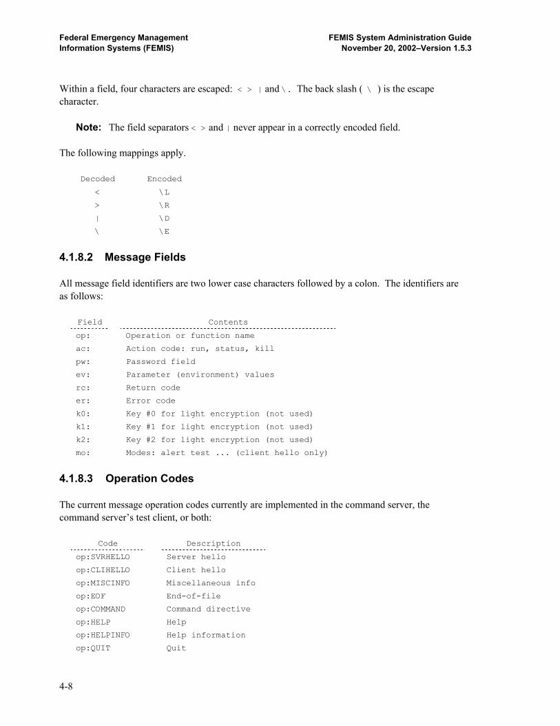
Federal Emergency Management FEMIS System Administration Guide Information Systems (FEMIS) November 20, 2002–Version 1.5.3
Within a field, four characters are escaped: < > | and \. The back slash ( \ ) is the escape character. Note: The field separators < > and | never appear in a correctly encoded field. The following mappings apply.
Decoded Encoded
< \L
> \R
| \D
\ \E
4.1.8.2 Message Fields All message field identifiers are two lower case characters followed by a colon. The identifiers are as follows:
Field Contents
op: Operation or function name
ac: Action code: run, status, kill
pw: Password field
ev: Parameter (environment) values
rc: Return code
er: Error code
k0: Key #0 for light encryption (not used)
k1: Key #1 for light encryption (not used)
k2: Key #2 for light encryption (not used)
mo: Modes: alert test ... (client hello only)
4.1.8.3 Operation Codes The current message operation codes currently are implemented in the command server, the command server’s test client, or both:
Code Description
op:SVRHELLO Server hello
op:CLIHELLO Client hello
op:MISCINFO Miscellaneous info
op:EOF End-of-file
op:COMMAND Command directive
op:HELP Help
op:HELPINFO Help information
op:QUIT Quit
4-8
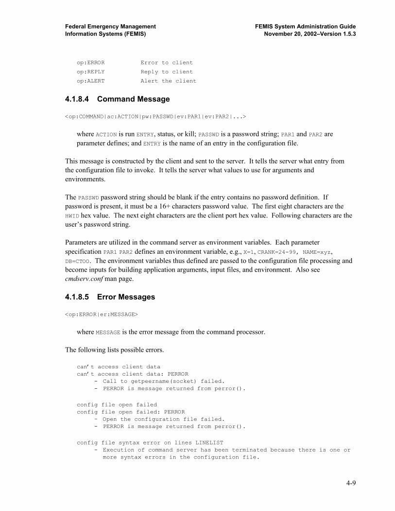
Federal Emergency Management FEMIS System Administration Guide Information Systems (FEMIS) November 20, 2002–Version 1.5.3
op:ERROR Error to client
op:REPLY Reply to client
op:ALERT Alert the client
4.1.8.4 Command Message <op:COMMAND|ac:ACTION|pw:PASSWD|ev:PAR1|ev:PAR2|...>
where ACTION is run ENTRY, status, or kill; PASSWD is a password string; PAR1 and PAR2 are
parameter defines; and ENTRY is the name of an entry in the configuration file. This message is constructed by the client and sent to the server. It tells the server what entry from the configuration file to invoke. It tells the server what values to use for arguments and environments. The PASSWD password string should be blank if the entry contains no password definition. If password is present, it must be a 16+ characters password value. The first eight characters are the HWID hex value. The next eight characters are the client port hex value. Following characters are the user’s password string. Parameters are utilized in the command server as environment variables. Each parameter specification PAR1 PAR2 defines an environment variable, e.g., X=1, CRANK=24-99, NAME=xyz, DB=CTOO. The environment variables thus defined are passed to the configuration file processing and become inputs for building application arguments, input files, and environment. Also see cmdserv.conf man page. 4.1.8.5 Error Messages <op:ERROR|er:MESSAGE>
where MESSAGE is the error message from the command processor. The following lists possible errors. can’t access client data can’t access client data: PERROR - Call to getpeername(socket) failed. - PERROR is message returned from perror().
config file open failed config file open failed: PERROR - Open the configuration file failed. - PERROR is message returned from perror().
config file syntax error on lines LINELIST - Execution of command server has been terminated because there is one or more syntax errors in the configuration file.
4-9
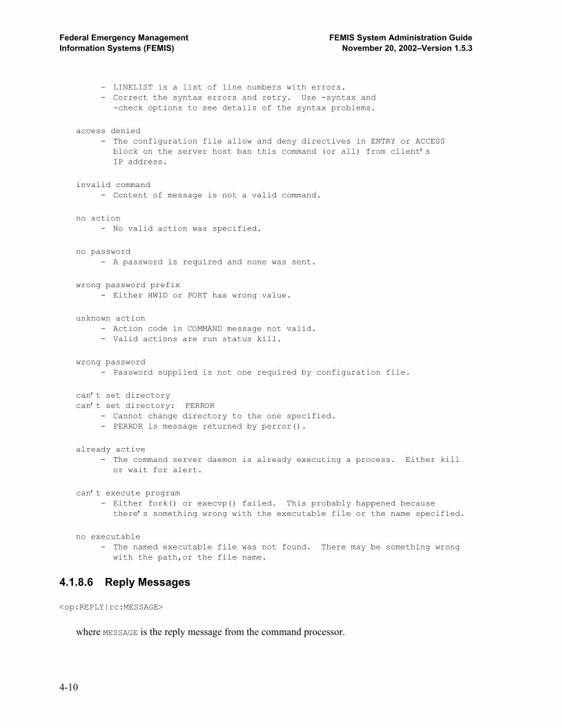
Federal Emergency Management FEMIS System Administration Guide Information Systems (FEMIS) November 20, 2002–Version 1.5.3
- LINELIST is a list of line numbers with errors. - Correct the syntax errors and retry. Use -syntax and -check options to see details of the syntax problems.
access denied - The configuration file allow and deny directives in ENTRY or ACCESS block on the server host ban this command (or all) from client’s IP address.
invalid command - Content of message is not a valid command.
no action - No valid action was specified.
no password - A password is required and none was sent.
wrong password prefix - Either HWID or PORT has wrong value.
unknown action - Action code in COMMAND message not valid. - Valid actions are run status kill.
wrong password - Password supplied is not one required by configuration file.
can’t set directory can’t set directory: PERROR - Cannot change directory to the one specified. - PERROR is message returned by perror().
already active - The command server daemon is already executing a process. Either kill or wait for alert.
can’t execute program - Either fork() or execvp() failed. This probably happened because there’s something wrong with the executable file or the name specified.
no executable - The named executable file was not found. There may be something wrong with the path,or the file name.
4.1.8.6 Reply Messages <op:REPLY|rc:MESSAGE>
where MESSAGE is the reply message from the command processor.
4-10
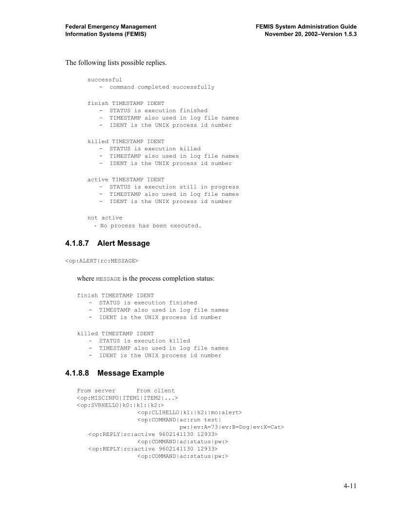
Federal Emergency Management FEMIS System Administration Guide Information Systems (FEMIS) November 20, 2002–Version 1.5.3
The following lists possible replies. successful - command completed successfully
finish TIMESTAMP IDENT - STATUS is execution finished - TIMESTAMP also used in log file names - IDENT is the UNIX process id number
killed TIMESTAMP IDENT - STATUS is execution killed - TIMESTAMP also used in log file names - IDENT is the UNIX process id number
active TIMESTAMP IDENT - STATUS is execution still in progress - TIMESTAMP also used in log file names - IDENT is the UNIX process id number
not active
- No process has been executed. 4.1.8.7 Alert Message <op:ALERT|rc:MESSAGE>
where MESSAGE is the process completion status: finish TIMESTAMP IDENT - STATUS is execution finished - TIMESTAMP also used in log file names - IDENT is the UNIX process id number
killed TIMESTAMP IDENT - STATUS is execution killed - TIMESTAMP also used in log file names - IDENT is the UNIX process id number
4.1.8.8 Message Example From server From client <op:MISCINFO|ITEM1|ITEM2|...> <op:SVRHELLO|k0:|k1:|k2:> <op:CLIHELLO|k1:|k2:|mo:alert> <op:COMMAND|ac:run test| pw:|ev:A=73|ev:B=Dog|ev:X=Cat> <op:REPLY|rc:active 9602141130 12933> <op:COMMAND|ac:status|pw:> <op:REPLY|rc:active 9602141130 12933> <op:COMMAND|ac:status|pw:>
4-11

Federal Emergency Management FEMIS System Administration Guide Information Systems (FEMIS) November 20, 2002–Version 1.5.3
<op:REPLY|rc:active 9602141130 12933> <op:ALERT|rc:finish 9602141130 12933>
4.1.9 Service Port and Name The cmdservd service port number currently is 9015. The short name is femis-cmdserv or fxcmdserv. 4.1.10 Files Files utilized during the installation and execution of the FEMIS command server include the following: - /home/femis/bin/cmdservd daemon executable - /home/femis/bin/cmdserv test client (UNIX)
- /home/femis/etc/cmdserv.conf configuration file
- /etc/services service port numbers - /etc/inetd.conf internet daemon config
4.2 cmdserv.conf – FEMIS Command Server Configuration File
4.2.1 Availability The FEMIS command server configuration file cmdserv.conf is included with the FEMIS application. The default location of the file is /home/femis/etc on the FEMIS UNIX data server. 4.2.2 Description This configuration file provides specific configuration information to the FEMIS command server daemon cmdservd. Unlike problematic remote compute servers such as RSH, the FEMIS command server provides some degree of security through this configuration file. Security is also realized by placing severe limits on what this command server is allowed to do. Only those procedures defined in the configuration file can be spawned. Additional security is realized through an encrypted password mechanism. cmdservd currently uses simple encryption, with RSA or SSL planned for the future. The FEMIS project and a CSEPP site administrator have the ability to configure allowed and denied clients on a per site basis. Allow and deny directives give the administrator the ability to allow individual workstations in the local EOC, or a remote EOC, but deny all others. Specification of allowed and denied workstations is based on IP address.
4-12
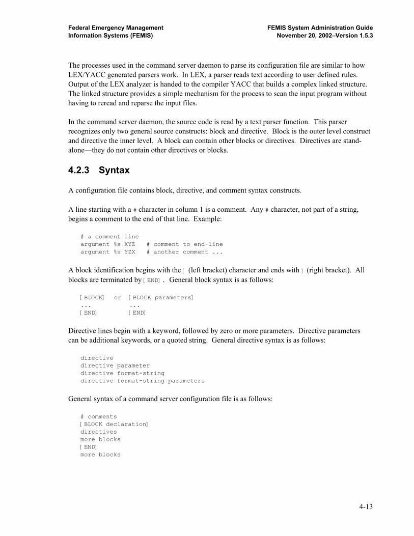
Federal Emergency Management FEMIS System Administration Guide Information Systems (FEMIS) November 20, 2002–Version 1.5.3
The processes used in the command server daemon to parse its configuration file are similar to how LEX/YACC generated parsers work. In LEX, a parser reads text according to user defined rules. Output of the LEX analyzer is handed to the compiler YACC that builds a complex linked structure. The linked structure provides a simple mechanism for the process to scan the input program without having to reread and reparse the input files. In the command server daemon, the source code is read by a text parser function. This parser recognizes only two general source constructs: block and directive. Block is the outer level construct and directive the inner level. A block can contain other blocks or directives. Directives are stand-alone—they do not contain other directives or blocks. 4.2.3 Syntax A configuration file contains block, directive, and comment syntax constructs. A line starting with a # character in column 1 is a comment. Any # character, not part of a string, begins a comment to the end of that line. Example: # a comment line argument %s XYZ # comment to end-line argument %s YZX # another comment ...
A block identification begins with the [ (left bracket) character and ends with ] (right bracket). All blocks are terminated by [END]. General block syntax is as follows: [BLOCK] or [BLOCK parameters] ... ... [END] [END]
Directive lines begin with a keyword, followed by zero or more parameters. Directive parameters can be additional keywords, or a quoted string. General directive syntax is as follows: directive directive parameter directive format-string directive format-string parameters
General syntax of a command server configuration file is as follows: # comments [BLOCK declaration] directives more blocks [END] more blocks
4-13

Federal Emergency Management FEMIS System Administration Guide Information Systems (FEMIS) November 20, 2002–Version 1.5.3
4.2.4 Block Syntax The command server configuration language utilizes five block types: ACCESS, ENTRY, HOST, SITE, and ALL. A block statement always begins with the [ (left bracket) character, is followed by the block type name, and ends with ] (right bracket). Whether parameters are required is a function of block type. The block types and their summary purpose are as follows:
Block Type Purpose
[ACCESS] Begin access specification block
[ENTRY entname] Begin entry block (conditional)
[HOST hostlist] Begin host block (conditional on host)
[SITE sitelist] Begin site block (conditional on site)
[ALL] Begin unconditional block
[END ...] Marks end of a block
In the ACCESS block, a parameter after the block type is not required nor is one allowed. Likewise, the ALL block does not require a following parameter, nor is one allowed. An ENTRY block requires one and only one parameter, the entry name. The HOST and SITE blocks require a list of one or more parameters, where the parameters are names of hosts or names of sites. The END statement must have the characters [ENDxxx], where xxx is zero or more unprocessed characters, i.e., the parser scans only for [END. Characters xxx are only for commentary purposes, i.e., [END of block]. Every block must be terminated by an [END] statement, which marks the end of the block. A simple example of command server configuration file structure follows: # # a comment line # [HOST princess queen] # if host is princess or queen [ENTRY travelcost] # then define entry travelcost ... [END of travelcost] [ENTRY distance] # and define entry distance ... [END of distance] [END of princess queen]
The following sections contain detailed descriptions of each block type.
4-14
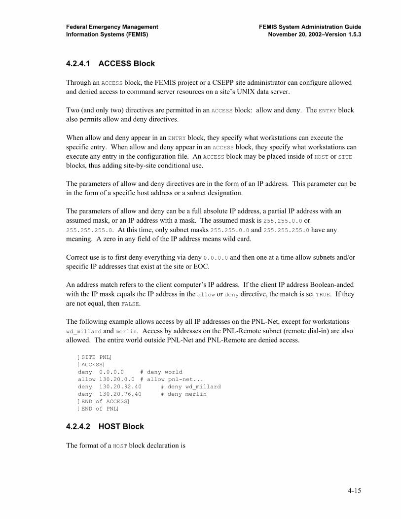
Federal Emergency Management FEMIS System Administration Guide Information Systems (FEMIS) November 20, 2002–Version 1.5.3
4.2.4.1 ACCESS Block Through an ACCESS block, the FEMIS project or a CSEPP site administrator can configure allowed and denied access to command server resources on a site’s UNIX data server. Two (and only two) directives are permitted in an ACCESS block: allow and deny. The ENTRY block also permits allow and deny directives. When allow and deny appear in an ENTRY block, they specify what workstations can execute the specific entry. When allow and deny appear in an ACCESS block, they specify what workstations can execute any entry in the configuration file. An ACCESS block may be placed inside of HOST or SITE blocks, thus adding site-by-site conditional use. The parameters of allow and deny directives are in the form of an IP address. This parameter can be in the form of a specific host address or a subnet designation. The parameters of allow and deny can be a full absolute IP address, a partial IP address with an assumed mask, or an IP address with a mask. The assumed mask is 255.255.0.0 or 255.255.255.0. At this time, only subnet masks 255.255.0.0 and 255.255.255.0 have any meaning. A zero in any field of the IP address means wild card. Correct use is to first deny everything via deny 0.0.0.0 and then one at a time allow subnets and/or specific IP addresses that exist at the site or EOC. An address match refers to the client computer’s IP address. If the client IP address Boolean-anded with the IP mask equals the IP address in the allow or deny directive, the match is set TRUE. If they are not equal, then FALSE. The following example allows access by all IP addresses on the PNL-Net, except for workstations wd_millard and merlin. Access by addresses on the PNL-Remote subnet (remote dial-in) are also allowed. The entire world outside PNL-Net and PNL-Remote are denied access. [SITE PNL] [ACCESS] deny 0.0.0.0 # deny world allow 130.20.0.0 # allow pnl-net... deny 130.20.92.40 # deny wd_millard deny 130.20.76.40 # deny merlin [END of ACCESS] [END of PNL]
4.2.4.2 HOST Block The format of a HOST block declaration is
4-15

Federal Emergency Management FEMIS System Administration Guide Information Systems (FEMIS) November 20, 2002–Version 1.5.3
[HOST host1 host2 host3 ...]
where: host1 host2 is a list of one or more host names. The HOST block is a conditional block which is compiled only if the server host, on which the command server daemon cmdservd is executing, is contained in the list of permitted hosts, i.e., the HOST block parameter list. The following example defines the site to be PNNL, only if the name of the command server host is virus, locusts, temblor, or mirage. The example code fragment also sets up access for the site. [HOST virus locusts temblor mirage] site PNNL # site name is PNNL [END] [SITE PNNL] [ACCESS] deny 0.0.0.0 # deny whole world allow 130.20.92.0 # allow isb1-400-pod subnet allow 130.20.194.0 # allow pnl-femis-1 subnet allow 130.20.210.0 # allow pnl-femis-2 subnet allow 130.20.226.0 # allow pnl-femis-3 subnet allow 130.20.242.0 # allow pnl-femis-4 subnet [END] [END]
4.2.4.3 SITE Block The format of a SITE block declaration is [SITE site1 site2 ...]
where: site1 site2 is a list of one or more site names. The SITE block is a conditional block that is compiled only if the server host, on which the command server daemon cmdservd is executing, is within one of the sites listed. The specific site is determined by the site directive. In the following example, the ENTRY definitions are compiled only if the local host is in one of the named sites: PNNL, TEAD, and UMDA. [SITE PNNL TEAD UMDA] [ENTRY import] ... [END] [ENTRY execute] ... [END] [END]
4-16

Federal Emergency Management FEMIS System Administration Guide Information Systems (FEMIS) November 20, 2002–Version 1.5.3
4.2.4.4 ALL Block The command server configuration file syntax rules require that all directives be contained inside of a block. Thus, a directive cannot be placed at the outer most level, as only blocks are allowed at that level. In most cases, directives are not needed except inside blocks. However, there are special cases where placing a directive at the outer most block is necessary. The ALL block effectively allows that case. The ALL block is like a conditional block that is always TRUE. It might be used where a HOST or SITE block would be used, however the ALL block always compiles. One special case that requires an ALL block is definition of global environment variables. Consider the following example. [ALL] environment DATABASE fi7 [END] [HOST virus] environment DATABASE fi6 [END]
In the example above, environment database is first defined to be fi7, all the time. Then if the host is virus, DATABASE is redefined to be fi6. 4.2.4.5 ENTRY Block An ENTRY block defines a block of code that is used in the command server to set up the execution of a child subprocess. The command, script, or executable to be spawned can be a compiled program, a Bourne script, a C Shell script, or a PERL script. The executable directive tells the command server where to find the entry’s application file. Other directives set up arguments, parameters, and data being passed to the application. The directive types permitted within an ENTRY block are as follows: executable, directory, password, outfile, errfile, argument, environment, file,
put, allow, and deny.
The parameter in the ENTRY statement is the entry name, which the command server matches with the parameter in a run command message from a client. See cmdservd(1) man page. Example: <op:COMMAND|ac:run entry-name|...>
4-17
Federal Emergency Management FEMIS System Administration Guide Information Systems (FEMIS) November 20, 2002–Version 1.5.3
4.2.5 Directive Syntax and Semantics In the command server configuration language, blocks define the structure of a configuration program, and directives define actions to be executed at some point. Directives are coded on a single line, which does not begin with the [ (left bracket) or # (comment) character. Generally, a directive consists of the directive type name, followed by an optional format statement, followed by one or more parameters. Directives utilize a format string that appears much like the format strings of the C programming language. In this language, only the %s conversion type is valid, i.e., %d %x %u are not supported and, if included in a format, produce an error. Any number of %s conversions can appear in a format string. This is the way in which data from the client program is passed on to the application. The parameters in a directive statement can be a simple string or the name of an environment variable. Environment names utilized get their values from the COMMAND:run messages from a client. In the example below, variables A, B, and C get values 1, 73, and 88X. All values are string values. Example: <op:COMMAND|ac:run x|ev:A=1|B=73|C=88X|...>
Following is a table of directives in the command server language:
Directive Purpose
site Define the name of a site
executable Define name of executable file
directory Define default directory
password Define password
outfile Name the stdout file
errfile Name the stderr file
argument Specify a command line argument
environment Specify an environment variable
file Open and write a file
put Put record into opened file
allow Allow access by client
deny Deny access by client
Three methods have been provided in the command server configuration language for copying input parameters to the application: argument, environment, and file/put. Argument generates an application command line argument. Environment creates an environment variable that then gets duplicated in the application. File/put creates a file that can be read by the application.
4-18

Federal Emergency Management FEMIS System Administration Guide Information Systems (FEMIS) November 20, 2002–Version 1.5.3
4.2.5.1 Site Directive The site directive defines the name of the site. This site name is then utilized in SITE blocks to conditionalize other blocks. The site directive is only valid inside a HOST block. Example: # [HOST virus locusts temblor mirage] site PNL [END] # [HOST cemsun tcemsun] site UTAH [END] # [SITE PNL] environment DATAPATH /files3/home/femis/data/pnl/ [END] [SITE UTAH] environment DATAPATH /files1/home/femis/data/utah/ [END] # [ENTRY xyz] ... argument %s DATAPATH [END]
Note: The same thing could be accomplished by using only the HOST block. However,
SITE provides a convenient shorthand way to group a list of hosts that exist at the different CSEPP sites.
In the example above, the environment variable DATAPATH is changed depending on site value. Placing the definition of DATAPATH outside the ENTRY blocks helps to decrease the amount of configuration file code necessary. 4.2.5.2 Executable Directive The executable directive provides the command server daemon with the executable file name. Possible formats are executable file-name executable format parameter-list
where file-name is an absolute. Only the string data type is supported—no integer or floating
data.
4-19
Federal Emergency Management FEMIS System Administration Guide Information Systems (FEMIS) November 20, 2002–Version 1.5.3
Format is a cmdserv allowed format (see above). Parameter list is a list of internal environment variable names. The number of environments in the list must match the number of %s designators in the format string. The executable directive requires that the environment variables used to generate the file name must be internal only. For this directive, external (client) environments are not allowed. The command server daemon does not allow the client to override the value of a previously specified environment if that environment is then used in the name of an executable, which would constitute a significant security hole. Examples: executable /home/femis/bin/import.sh
environment EXEPATH /home/femis/bin/esim/ executable %s/import.sh EXEPATH
In the examples above, the first example is valid because it is static and does not involve environments. The second example also is valid, provided the client does not override the value of environment EXEPATH. 4.2.5.3 Directory Directive The directory directive provides the command server daemon with the path to use for the current directory prior to running the application. See chdir(2) man page. Possible formats are directory path-name directory format parameter-list
where path-name is an absolute. Only the string data type is supported—no integer or floating
data. Format is a cmdserv allowed format (see above). Parameter-list is a list of environment variable names, which may be internal and/or external (client generated). The number of environments in the list must match the number of %s designators in the format string. If cmdservd can not set directory to the specified path, it returns an error message to the client, and does not run the application. 4.2.5.4 Password Directive The password directive provides the command server daemon with the password to use for this application. The password string can be blank. If the password directive is omitted, it is assumed to be blank. A blank password means that password checking is not performed in cmdservd prior to running the application. Possible formats are
4-20

Federal Emergency Management FEMIS System Administration Guide Information Systems (FEMIS) November 20, 2002–Version 1.5.3
password password-string password format parameter-list
where password-string is the full password specification. Only the string data type is
supported—no integer or floating data. Format is a cmdserv allowed format (see above). Parameter-list is a list of internal environment variable names. The number of environments in the list must match the number of %s designators in the format string. The password directive requires that the environment variables used to produce the password string must be internal only. For this directive, external (client) environments are not allowed. The command server daemon does not allow the client to override the value of a previously specified environment if that environment is then used in a password directive, which would constitute a significant security hole because the client could specify its own password. If the password directive specifies a non-blank string, cmdservd then requires the client to send a password string in the COMMAND message. That password must match the one generated in the password directive. If a match is not realized, cmdservd returns an error message to the client, and does not run the application. Examples: password georgewashington
password Elisabeth-2
environment SPORT Baseball environment TEAM SeattleMariners environment PLAYER Ichiro password %s-%s TEAM PLAYER
The first and second examples specify valid passwords because they are static and do not involve any environments. The third example also is valid, provided the client does not override the value of environments TEAM or PLAYER. 4.2.5.5 Outfile Directive The outfile directive tells the command server daemon the file name of where to write the application’s standard output. If no /path is included in the outfile directive, the file will be written to the default directory. If outfile and errfile specify the same string, only one file is created and stdout and stderr point to the same descriptor.
4-21

Federal Emergency Management FEMIS System Administration Guide Information Systems (FEMIS) November 20, 2002–Version 1.5.3
Possible formats are outfile file-name outfile format parameter-list
where file-name is a full or partial file specification. Only the string data type is supported—no
integer or floating data. Format is a cmdserv allowed format (see above). Parameter-list is a list of environment variable names, which may be internal and/or external (client generated). The number of environments in the list must match the number of %s designators in the format string. 4.2.5.6 Errfile Directive The errfile directive tells the command server daemon the file name of where to write the application’s standard error. If no /path is included in the errfile directive, the file will be written to the default directory. If errfile and outfile specify the same string, only one file is created and stdout and stderr point to the same descriptor. Possible formats are errfile file-name errfile format parameter-list
where file-name is a full or partial file specification. Only string data type is supported—no
integer or floating data. Format is a cmdserv allowed format (see above). Parameter-list is a list of environment variable names, which may be internal and/or external (client generated). The number of environments in the list must match the number of %s designators in the format string. 4.2.5.7 Argument Directive The argument directive tells cmdservd to copy the directive parameter(s) to the application’s command line arguments in the order given. See execve(2) man page. Possible formats argument argument-string argument format parameter-list
where argument-string is one full argument in string format. Only string data type is
supported—no integer or floating data.
4-22
Federal Emergency Management FEMIS System Administration Guide Information Systems (FEMIS) November 20, 2002–Version 1.5.3
Format is a cmdserv allowed format (see above). Parameter-list is a list of environment variable names, which may be internal and/or external (client generated). The number of environments in the list must match the number of %s designators in the format string. Examples: argument -x argument inputfile.dat argument %s-%s TEAM PLAYER
4.2.5.8 Environment Directive An environment directive tells cmdservd to define an environment variable in cmdservd process space. See setenv(1) and putenv(3) man pages. Environment variables can be used to generate the other application attributes, i.e., arguments, directory, file names. Environment variables also are inherited by the child process, and thus can be used to transmit data to the application. In some cases, this method of transmitting input parameters to the child has an advantage over using the argument directive. Those situations include when security is an issue, because using UNIX can make arguments visible via the ps command. Possible formats are environment env-name env-value-string environment env-name format parameter-list
where env-name is the environment variable name. Env-value string is the environment
variable value. Only string data type is supported—no integer or floating data. Format is a cmdserv allowed format (see above). Parameter-list is a list of environment variable names, which may be internal and/or external (client generated). The number of environments in the list must match the number of %s designators in the format string. Note: Environment variables subsequently used in executable or password directives,
which are affected by the client message, are not allowed. The command server daemon terminates the entry and does not run the specific application, because to do so would constitute a security hole. In other words, the client can not specify its own password nor its own executable file. Only the configuration file can do that.
Examples: environment OPTION -x environment SPORT BBall environment TEAM SeattleSuperSonics environment PLAYER Payton environment TEAMPLAYER %s.%s TEAM PLAYER
4-23

Federal Emergency Management FEMIS System Administration Guide Information Systems (FEMIS) November 20, 2002–Version 1.5.3
4.2.5.9 File Directive The file directive instructs cmdservd to create and open a new file to receive records. Records are written to the file via the put directive. Possible formats are file file-name file format parameter-list
where file-name is either a full or partial file specification. If a relative file name, the default
directory is utilized as the starting point. Format is a cmdserv allowed format (see above). Parameter-list is a list of environment variable names, which may be internal and/or external (client generated). The number of environments in the list must match the number of %s designators in the format string. Examples: file /home/femis/user/evlog/10000745/e0/ file /home/femis/user/evlog/%s/e%s/pf CASE EXER
In the first example, the file directive uses a full path specification involving no variables. The second example utilizes two variables CASE and EXER, assumed to be sent by the client. A command server configuration file entry can utilize multiple file directives, in which case multiple files are created. 4.2.5.10 Put Directive The put directive instructs cmdservd to copy one record into the file created and opened by the most recent file directive. Possible formats are put record-text put format parameter-list
where record-text is the actual and full record text to be copied into the currently opened file. Format is a cmdserv allowed format (see above). Parameter-list is a list of environment variable names, which may be internal and/or external (client generated). The number of environments in the list must match the number of %s designators in the format string. Examples:
4-24
Federal Emergency Management FEMIS System Administration Guide Information Systems (FEMIS) November 20, 2002–Version 1.5.3
put “The quick brown fox jumped over the lazy dog.” put %s-%s CASE EXER
environment ANIMAL elephant. put “The quick brown fox jumped over the %s.” ANIMAL
The first example copies a fixed static string into the file. The second utilizes a format string and two environment variables. The third example uses a quoted string as the format and one environment variable. The ANIMAL value could be provided in a message from the client. 4.2.5.11 Allow Directive A description of the allow directive is also included in ACCESS block documentation. Combinations of allow and deny can be used in ACCESS and ENTRY blocks to describe the permitted users of the command server. Syntax of the allow directive is the keyword allow, followed by an IP address or subnet, followed by an optional subnet mask, followed by an optional comment. Format of IP address and subnet mask currently is four decimal numbers, in the range 0-255, separated by decimal point. Allowed IP address elements are 0-255. Allowed IP mask elements are 0, 128, 192, 224, 240, 248, 252, 254, and 255. Subnet mask must be in the format 255...XXX.0..., where 255 can appear one, two or three times; 0 can appear one, two, or three times; and XXX (not 0 or 255) can appear only one time. Examples: allow 0.0.0.0 # world allow 130.20.0.0 255.255.0.0 # pnl net allow 192.101.108.0 255.255.255.0 # pnl-remote allow 130.20.92.131 # workstation allow 201.8.44.64 255 255.255.224 # subnet
4.2.5.12 Deny Directive A description of the deny directive is included in the ACCESS block documentation. Combinations of allow and deny can be used in ACCESS and ENTRY blocks to describe the permitted users of the command server. Syntax of the deny directive is the keyword allow, followed by an IP address or subnet, followed by a subnet mask, followed by optional comments. Format of IP address and subnet mask currently is four decimal numbers, in the range 0-255, separated by decimal point. Allowed IP address elements are 0-255.
4-25
Federal Emergency Management FEMIS System Administration Guide Information Systems (FEMIS) November 20, 2002–Version 1.5.3
Allowed IP mask elements are 0, 128, 192, 224, 240, 248, 252, 254, and 255. Subnet mask must be in the format 255...XXX.0..., where 255 can appear one, two or three times; 0 can appear one, two, or three times; and XXX (not 0 or 255) can appear only one time. Examples:
deny 0.0.0.0 # world deny 196.104.8.0 # subnet deny 130.20.92.87 # workstation deny 201.8.44.32 255.255.255.224 # subnet deny 201.8.44.96 255.255.255.224 # subnet
4.3 cmdserv – FEMIS Command Server Test Client (UNIX) 4.3.1 Synopsis cmdserv [-v] [-h] [-D] [-u] [[IPaddr] | [hostname]] [port]
4.3.2 Availability Program cmdserv is a test client for use with the FEMIS command server daemon cmdservd. The command server, test client, and related files are delivered in the FEMIS distribution tar file on magnetic tape or CD. The default locations for these files are /home/femis/bin and /home/femis/etc on the FEMIS UNIX data server. 4.3.3 Description FEMIS utilizes remote command servers, executing on a UNIX host computer in order that PC workstation users can launch large mathematical model/simulation codes, which on the PCs either could not be run at all or would require an unreasonable amount of time and resources. The command service consists of a client and server. The client runs on a Windows workstation. The server runs on UNIX and is capable of spawning processes at the request of a remote client. This program is a client for use on the UNIX platform. Its purpose is mainly for testing the command server, for testing of new configuration file scripts, and for testing executables. 4.3.4 Options The command server test client -v option produces a listing of current version information. Example: virus% cmdserv -v cmdserv version 1.0 - Wed Feb 14 14:41:00 PST 1996
The cmdserv -h option produces a help listing:
4-26

Federal Emergency Management FEMIS System Administration Guide Information Systems (FEMIS) November 20, 2002–Version 1.5.3
virus% cmdserv -h usage: cmdserv [-hvD] [IPaddr | host] [port] -v : display version information -h : display help messages -D : use unregistered service port (9015) Ipaddr : host IP address, e.g., 130.20.92.87 host : server’s host name, e.g., cemsun port : protocol or service port, e.g., 9015
The cmdserv -D option turns on diagnostics. Normally, the destination port is 9015, the standard service port for the FEMIS command server. Certain testing activities may require changing the cmdserv port number, thus the option to place it on the command line. The destination host must be specified either as an IP address, or as a host name. One or the other must be specified, but not both. The local host can be designated as the command server daemon by including minus sign ( - ) in place of the IP address or host name. Examples: virus% cmdserv locusts virus% cmdserv virus cemsun% cmdserv tcemsun cemsun% cmdserv cemsun virus% cmdserv - virus% cmdserv 130.20.92.87 locusts% cmdserv 130.20.28.43
4.3.5 Installation See the cmdservd(1) man page. 4.3.6 Protocol See the cmdservd(1) man page. 4.3.7 Operation Run the command service test client by entering cmdserv. Cmdserv first tries to connect with the command server daemon, cmdservd. Generally, any I/O error during execution of the test client will cause it to terminate. The possible errors during client operation are cmdserv: create socket failed: PERROR - Call to socket() library function to create a socket failed with the error
indicated. cmdserv: convert IP address failed: PERROR - Call to inet_addr() library function failed with the error indicated.
4-27

Federal Emergency Management FEMIS System Administration Guide Information Systems (FEMIS) November 20, 2002–Version 1.5.3
cmdserv: HOST - unknown host: PERROR - Call to gethostbyname() library function failed with the indicated error. cmdserv: HOST-OR-IP - connect failed: PERROR - The connect() library function call failed because of the indicated error. cmdserv: HOST-OR-IP - can’t get socket info: PERROR - Call to getsockname() library function failed because of the indicated error. cmdserv: read failed: PERROR - Call to recv() library function to receive a message on a socket failed with the error indicated. cmdserv: send failed: PERROR - Call to send() library function to transmit a message on a socket failed with the error indicated.
where HOST-OR-IP will be either the destination host name or the destination IP address
depending on how the command line was entered. And PERROR represents an error message returned from perror().
Once cmdserv receives control from the shell, it opens a connection to the specified destination host and prompts for an action. Action Prior to entering anything, wait for the server and client hello messages to be exchanged. Cmdserv displays two to three messages. Example: Received
<op:MISCINFO| program argv : cmdservd| program argc : 1| current dir : /files0/home/larryg/femis/command/log| config file : \LNull\R| daemon uid : 1033| getpeername : clen : 16| getpeername : gprc : 0| client port : 2377| client host : hattrick.pnl.gov| client Ipadd : 130.20.92.87| hwid number : 82145C57| server key : \Lnull\R| client key : \Lnull\R| process id : 10332| parent id : 146>
4-28
Federal Emergency Management FEMIS System Administration Guide Information Systems (FEMIS) November 20, 2002–Version 1.5.3
Received <op:SVRHELLO|F2BBE247|********|********>
Sending <op:CLIHELLO|********|********|mo:alert test >
Action At this point, enter one of the following: run X : runs entry X from configuration file status : returns status of current application kill : kills the current application
After entering run X, cmdserv prompts for a password. Password Either enter the password required by the configuration file or enter Return, if none is required. Also see the configuration file cmdserv.conf(5) man page. Cmdserv next prompts for any number of parameters. Parameters must be of the form VARIABLE=VALUE, where VARIABLE is the name of a variable in the command server, and VALUE is the value to be assigned. Note: All values are string values. Numeric, integer, and floating point data are not
supported in this implementation. Once all parameters have been entered, type return or ^D. As soon as the command server processes the command and starts the application, it sends a message back to cmdserv, which is displayed: Received <op:REPLY|rc:active TIMESTAMP PROCESS>
where TIMESTAMP is a 10 character time stamp, e.g., 9602071334, and PROCESS is the PID of the
child process. While the application is executing, entering status returns status of the application process. Once the application has terminated, the command server sends an alert message and cmdserv displays:
4-29

Federal Emergency Management FEMIS System Administration Guide Information Systems (FEMIS) November 20, 2002–Version 1.5.3
4-30
Received <op:ALERT|rc:finish TIMESTAMP PROCESS>
where TIMESTAMP and PROCESS are the same as above. Now enter another command or exit via ^C or ^D. 4.3.8 Messages Any of the possible command server daemon (cmdservd) error messages and reply messages can be received in the test client and thus be displayed on its standard output. See the cmdservd(1) man page. 4.3.9 Configuration File See the cmdserv.conf(5) man page. 4.3.10 Service Port and Name The cmdserv service port number currently is 9015. The short name is femis-cmdserv or fxcmdserv. 4.3.11 Files Files utilized during the installation and execution of the FEMIS command server include /home/femis/bin/cmdservd daemon executable /home/femis/etc/cmdserv.conf configuration file /home/femis/bin/cmdserv test client (UNIX) /etc/services service port numbers /etc/inetd.conf internet daemon config

5.0 FEMIS Meteorological Application The FEMIS meteorological application can obtain meteorological data in two ways. Meteorological data is transferred from EMIS to FEMIS using the FEMIS DEI. The second method is to use the FEMIS Met Data capability.
5.1 Meteorological Input Using the FEMIS DEI The FEMIS DEI automatically acquires operational meteorological data from EMIS and places it into the FEMIS meteorological tables. The DEI can also be configured to send a copy of the operational meteorological information into a specified FEMIS exercise. The option to store a copy of operational meteorological data in a selected exercise is not enabled when the DEI is installed at a site. This reduces the amount of disk space needed to store meteorological data and allows the site administrator to only get a copy of operational meteorological data when it is appropriate, such as during an exercise.
5.2 Meteorological Input Via the FEMIS Met Data FEMIS has a built-in Met data capability that allows a privileged user to enter operational and/or exercise meteorological values into the FEMIS meteorological tables. A privileged, onpost controller is expected to do this to input the specific meteorological values needed in an exercise. The Met data capability consists of the Met Conditions Status Board and Met towers, which are accessed from the Workbench menu bar by selecting Status Met Conditions and Data Met
Towers. A description of how this tool works is available in the FEMIS Help.
5-1

6.0 FEMIS Contact Daemon All network communication servers in FEMIS utilize the standard registered service port for making contact between all clients and all servers. By registered, we mean that the FEMIS project has requested registration for and received notification of a single TCP/IP service port from the Internet Assigned Number Authority (IANA). The name registered and port assigned are femis 1776. To implement the registered FEMIS service port on a server, the line femis 1776 has been added to the /etc/services file. Doing this tells inetd that any incoming connection request directed to port 1776 is intended for one of the four FEMIS server daemons: Met, notification, command, or monitor. Upon receiving a connection request on port femis 1776, inetd forks and executes the femisd program, the FEMIS contact protocol daemon. The only job of femisd is to figure out which of the four service protocols the client application needs. This is done by reading a single message from the client that contains the requested protocol name and a list of parameters. femisd then executes the correct protocol handler and passes control to it. All communication with the protocol handler then takes place over the socket established in inetd.
6.1 Message Format The message format which clients utilize to communicate with femisd is <pro:P|env:E|arg:A> where P is the protocol name, E is an environment specification, and A is an argument specification for the process to be executed. The femisd message can contain any number of environment and argument messages. Environment specifications are used to modify the process environment prior to calling the protocol server. Arguments are passed to the protocol server on the command line.
6.2 Configuration File This section discusses the format of the femisd configuration file. The contact daemon configuration file default location is /home/femis/etc/femisd.conf. This can be over-ridden by the -conf <file> command line option. Any line starting with a # is a comment line. A line debuglevel NUMBER specifies the level of debug output in the log file /home/femis/log/femisd.log. NUMBER is 0, 1, 2, or 3. The value 0 is the least verbose, and the value 3 is the most verbose. Use the higher values of debuglevel only for debugging and diagnostic. Using debuglevel 3 fills up the disk quickly. A line PROTOCOL EXECUTABLE OPTIONS is the way to specify an interface to a protocol handler. Presently there are protocol handlers for command server, FEMIS monitor daemon, and notification server. The names are cmdservd, femismond, and fxnotify.
6-1
Federal Emergency Management FEMIS System Administration Guide Information Systems (FEMIS) November 20, 2002–Version 1.5.3
6-2
Notification PROTOCOL numbers are usually in the range 9000-9999. These are not port numbers. The port number is always 1776. EXECUTABLE is the full executable path/name to the protocol handler. Example: normal notification protocol handler is /home/femis/bin/fxnotify. OPTIONS is a list of special command line switches. They are
OPTIONS string < %N -- %P %C %J -H %H > is currently included on every line in the femisd configuration file. These specify program name, protocol number, client host, client port number, and home directory. Option %N is substituted for by the femisd program name string. Option %V is substituted for by the femisd version number string. Option %H is substituted for by the home directory string. Option %U is substituted for by the UID code of the femisd process. Option %A is substituted for by the architecture string from uname. Option %M is substituted for by the machine type string from uname. Option %S is substituted for by the host name of the server. Option %C is substituted for by the host name of the client. Option %I is substituted for by the IP address of the client. Option %J is substituted for by the client port number of the client. Option %R is substituted for by the process id number of the FEMIS process. Option %P is substituted for by the protocol name part of the message. Option %D is substituted for by the current date in YYYYMMDD format. Option %T is substituted for by the current time in HHMMSS format. Option %F is substituted for by the full time stamp in YYYYMMDDHHMMSS format. Option %E(V) is substituted for by the value of environment variable is V. Note: The purpose of these and other options is to create unique and different log file names
from parameters readily available to the femisd program.
7.0 FEMIS Data Exchange Interface (DEI) The FEMIS/EMIS Data Exchange Interface (DEI) system is used to support the transfer of data from EMIS to FEMIS. The FEMIS/EMIS DEI system consists of one main program (femisdei) for processing data sent from EMIS and a utility program (fprofdei) for maintaining the encrypted password file for File Transfer Protocol (FTP). Both programs run on the FEMIS onpost UNIX computer, the former usually as a background process. The files are sent from EMIS via FTP to an Internet Protocol (IP) address and some files come back from them in a particular directory. At most, two changes need to be made to EMIS, both on the UNIX computer. 1. The setup.ini file may need to be changed to specify the EMIS UNIX user account for
incoming files (and the account created if it does not exist). 2. The template file in the EMIS UNIX user’s home directory needs to be changed to point to the
new IP address, FEMIS UNIX user account, and account password.
7.1 Software and Hardware Components 7.1.1 Software Components The two DEI software components are 1. FEMIS/EMIS Data Exchange Interface program – femisdei
2. FEMIS/EMIS FTP Profile Manager – fprofdei 7.1.2 Hardware Components The two DEI hardware components are 1. FEMIS onpost UNIX computer
2. EMIS computers (PC and UNIX)
7.2 Program Detail – femisdei The femisdei program processes files received from EMIS. It is a PRO*C program which connects to an Oracle database and loads data into various tables. The program has three distinct phases of operation: startup, processing loop, and shutdown.
7-1
Federal Emergency Management FEMIS System Administration Guide Information Systems (FEMIS) November 20, 2002–Version 1.5.3
7.2.1 Startup Phase During the startup phase, the program sets some default configuration items, processes the configuration file and overrides the default setup, and then processes the command line options which override all previous settings. If everything is working so far, it connects to the Oracle database. If able to connect, it then checks to see if the specified FEMIS exercise exists. If not, the program displays a warning message and continues. Then, if you want it to run as a background process (the -clone command line option or the CLONE configuration file option) as it normally does, it moves itself into background. 7.2.2 Processing Loop Phase Next, the program begins the processing loop, where it waits for a transfer list file, xferlist.dat, to appear in the /home/femx directory. When the file appears, FEMIS DEI moves the EMIS files to the from directory, reads the header, and determines whether the accompanying files are real or exercise data. It reads and processes the entries one file at a time, sends notifications of new data to the FEMIS Notification server via the fev client, and sends a KEY.DAT file back to EMIS using FTP to acknowledge receipt of the files. Then it waits for another transfer list file. Generically, processing a data file consists of 1. Reading the file header 2. Adding an entry to the FEMIS journal that the file was received from EMIS 3. Reading the data in the file 4. Converting the data into FEMIS terms 5. Putting the results into the Oracle tables 6. Adding entries to the FEMIS journal that the file was successfully processed 7. Adding entries to the notification list 8. Adding an entry to the acknowledgment key list 9 Sending the acknowledgment back to EMIS. EMIS can send many types of files, but femisdei only loads the data in a few of them. These are NOTIFY.DAT, D2INPnnn.DAT, WORKPLAN.DAT, and WEATHER.DAT. A KEY.DAT file with a Please Echo key or a PAR key will also be processed properly. All files from EMIS will be acknowledged, though the files that femisdei ignores will always be said to be good (DATA_OK). The other files may or may not be good based on the contents of each file. NOTIFY.DAT: If the transfer includes a Notification file, femisdei processes it first. It reads the entire file and then determines whether this is a new event, an update to an existing event, or closes one or all EMIS events.
7-2
Federal Emergency Management FEMIS System Administration Guide Information Systems (FEMIS) November 20, 2002–Version 1.5.3
To determine if one or more EMIS events are to be closed, the END EVENT Classification is used to close the specified event, and END ALL OPER EVENTS or END ALL EXER EVENTS is used to close all EMIS events. If only closing a single event, then the event in FEMIS with the same EMIS Event ID is ended. Otherwise all EMIS events in FEMIS in the proper mode (operations or exercise #n) are ended. The new versus update notification is determined by looking at the EMIS Event ID and the Notification Reason field. If there is an event in FEMIS with the same EMIS Event ID, the current notification is an update. Otherwise, it is a new event. For new events, the current operational D2PC case is linked to the event if the D2PC case is not older than the value specified in the D2PC_EVENT_DELTA_MINUTES field of the EOC_OBJECTIVE table. A record for the event notification is added to the CSEPP_Accident table. If the notification is an update notification, the CAI_STATUS_CODE flag for all previous records for that event are changed, leaving just the new record as the current one. D2INPnnn.DAT: After processing the notification file, femisdei processes the D2PC input file, if sent. First, it calculates the D2PC case number by extracting it from the name of the file (the nnn). Then it renumbers or deletes any D2PC cases in the database that have the same D2PC case number. The first available number greater than 1000 is used. (To check which cases were renumbered and which were deleted, check for KEEPD2 and NOKEEPD2 in the FEMISDEI.CFG file.) If the FEMIS Work Plan points to an old D2PC case with that number, the program makes it point to the new D2PC case, and then it adds an empty record in the database for the new D2PC case. It processes the file, loading the values into the various D2PC tables. If the D2PC case is a real one (not Reference or What-If), then it updates the Navigator table to point to the new D2PC case. (In other words, the D2PC case sent from EMIS becomes the current operational onpost case in FEMIS.) Finally, it adds an entry to the Case_Manager table for the new D2PC case. WORKPLAN.DAT: For each activity in the WORKPLAN.DAT file, FEMIS DEI reads the data from the file and adds an activity record to the FEMIS database. A number of the fields in this new activity record will be missing information because that information is not supplied by EMIS. A Local ID/MCE may be created. Local ID/MCEs are based on D2PC source term information, but the WORKPLAN.DAT file only specifies agent and munition. If no Local ID/MCE exists with the specified agent and munition, then a new Local ID/MCE will be created. When it is done processing the file, it sets the new Work Plan as the operational Work Plan. WEATHER.DAT: For each entry in the Weather file, it reads the record, finds the tower name associated with that tower ID, makes all existing meteorological records for that tower not current, and adds the new record–making it current. 7.2.3 Shutdown Phase The final phase, shutdown, usually will not occur. In fact, it can only occur if you run femisdei in One Pass mode, if you “kill” it with the kill file, femisdei.kil, if Oracle goes down, or if femisdei
7-3

Federal Emergency Management FEMIS System Administration Guide Information Systems (FEMIS) November 20, 2002–Version 1.5.3
crashes. The kill file causes femisdei to shutdown nicely, committing all outstanding database updates and disconnecting from Oracle. If you need to stop the femisdei program, type femisdei -kill to create a “kill” file named femisdei.kill. When the femisdei sees that this file exists, it will shut down nicely. While you can use the UNIX kill -9 command, it simply stops femisdei dead in its tracks and does not force database commits or the database disconnect to occur, and two things could happen that you do not want to happen. First, not all the data from EMIS will be saved in the Oracle database. Second, the Oracle connection may not immediately go away. This could prevent femisdei or other programs that access Oracle from getting a connection. Therefore, to stop the femisdei program, always use the femisdei -kill option.
7.3 Program Detail – fprofdei The fprofdei C program is used to maintain the FTP profile file. This file is usually named /home/femis/etc/femisdei.prf. It contains the hostname, username, and encrypted password for the EMIS UNIX computer to which femisdei will send acknowledgment files via FTP. It is analogous to the template file that EMIS uses to transfer files to FEMIS.
7.4 Configuring the Programs The FEMIS UNIX Installation scripts configure DEI automatically, you should not need to do anything. However, if you do need to configure the programs, the following procedures detail the configuration procedures for the femisdei and fprofdei programs. 7.4.1 Configuration – femisdei The femisdei program requires the following directory structure: /home/femis/bin - directory for executables /home/femis/etc - configuration files /home/femis/log - log files /home/femx - incoming files from EMIS /home/femx/dei/send - outgoing files to EMIS /home/femx/dei/from - saved files from EMIS
Note: ALL of the above directories are configurable, but this is the recommended setup.
The UNIX programs and support files are placed in the indicated locations when loaded from tape. /home/femis/bin/femisdei - executable file /home/femis/bin/fprofdei - executable file /home/femis/etc/femisdei.cfg - configuration file /home/femis/etc/femisdei.prf - configuration file
7-4
Federal Emergency Management FEMIS System Administration Guide Information Systems (FEMIS) November 20, 2002–Version 1.5.3
7.4.1.1 femisdei UNIX User Account femisdei requires a UNIX user account for receiving files from EMIS. The recommended setup is: • Username is femx. • Home directory is /home/femx. • Directory structure is /home/femx/ /home/femx/dei/from /home/femx/dei/send
• The femisdei program must be able to read and write to all of the directories. 7.4.1.2 femisdei FTP Profile File The femisdei program requires an FTP profile file, usually named /home/femis/etc/femisdei.prf. It is maintained with the fprofdei utility, which you should refer to for more information. 7.4.1.3 femisdei Configuration File The femisdei program requires a configuration file, usually named /home/femis/etc/femisdei.cfg. This file is automatically configured during installation, but you may need to change it later. Comment lines (blank or beginning with #) are ignored. Refer to the sample configuration file in Table 7.1 at the end of this section. ORACLE_SID
UNIX Oracle environment variable. This variable should be set correctly before femisdei starts.
ORACLE_HOME
UNIX Oracle environment variable. Should be set correctly before femisdei starts. PATH (recommend /home/femis/bin:/usr/bin): $ORACLE_HOME/bin UNIX PATH environment variable. Should be set correctly before femisdei starts. ORACLE_BASE
UNIX Oracle environment variable. Should be set correctly before femisdei starts.
7-5

Federal Emergency Management FEMIS System Administration Guide Information Systems (FEMIS) November 20, 2002–Version 1.5.3
DEIPATH (recommend /home/femx/dei/) Top-level directory under which the from and send directories must be located and where
femisdei puts files from EMIS or files it sends to EMIS. Make sure to include the slash ( / ) at the end. It can be overridden with the -dei <path> command line option.
EMISPATH (recommend /home/femx/) Home directory of the femx user, and directory where EMIS puts its files. Make sure to include
the slash ( / ) at the end. It can be overridden with the -ep <path> command line option. PROFILEFILE (recommend /home/femis/etc/femisdei.prf) Name of the FTP profile file which contains the hostname, username, and encrypted password of
the EMIS account to which femisdei will FTP files. It can be overridden with the -pf <fn> command line option.
HALTFILE (recommend /home/femis/log/femisdei.hlt) Name of the halt file that will cause femisdei to halt. When the file disappears, femisdei will
continue processing. This is also the file that gets created with the femisdei -halt command.
Note: If the file exists when femisdei starts, DEI will halt. KILLFILE (recommend /home/femis/log/femisdei.kil) Name of the kill file that will cause femisdei to exit gracefully. This is also the file that gets
created with the femisdei -kill command.
Note: If the file exists when femisdei starts, DEI will immediately exit, deleting this file. LOGFILE (recommend /home/femis/log/femisdei.log) Name of the output log file. It can be overridden with the -log <fn> or -nolog command line
options. FEVHOST, FEVPORT
Name of the FEMIS UNIX onpost computer and port number for use by the fev client for sending notifications of new data to the FEMIS Visual Basic applications. It can be overridden with the -fev <host> <port> command line option.
FTPHOST, FTPUSER, FTPPATH (recommend ./) Name of the EMIS UNIX computer, username, and path where femisdei will FTP files. It can
be overridden with the -ftp <host> <user> <path> command line option. EXERCISE (recommend 1) Exercise number into which exercise data from EMIS will be loaded. The exercise number does
not necessarily have to be a valid exercise in FEMIS–the data will be loaded anyway. It can be overridden with the -exercise <n> command line option.
7-6

Federal Emergency Management FEMIS System Administration Guide Information Systems (FEMIS) November 20, 2002–Version 1.5.3
SLEEP (recommend 1) The time interval that femisdei waits between checking for the xferlist.dat file from EMIS.
It should not be more than 10 seconds. It can be overridden with the -sleep <seconds> command line option.
DAIINT (recommend 60) The number of sleep intervals the femisdei should wait before checking for data
acknowledgments to be forwarded to EMIS. The period of data acknowledgment checks may be calculated by multiplying the SLEEP and DAIINT values. For example, if the SLEEP parameter is set to 2 seconds and the DAIINT is set to 30, then data acknowledgments will be checked once every 2*30 = 60 seconds.
It can be overridden with the -daiint <number sleep intervals> command line option. DEBUG (recommend DEBUG 0) The debug mode, which controls the detail of messages from femisdei. After you get femisdei
running properly, you should run in nodebug mode, which only lists the name of each file from EMIS as it gets processed. Debug level 0 gives slightly more detailed messages, and debug level 2 gives very detailed messages, which would be useless to anyone but the developer. It can be overridden with the -debug, -debug 1, -debug 2, and -nodebug command line options.
CLONE (recommend CLONE) Controls whether femisdei runs as a foreground (NOCLONE) or background (CLONE) process. For
testing purposes, you may want to run it in the foreground; but that means when you want to logout, the process will have to be killed. Normally, femisdei should be run as a background process. It can be overridden with the -clone and -noclone command line options.
CLEAN (recommend CLEAN) Controls whether temporary files are deleted or left around. Both fev.csh and ftp.csh are
temporary files created and executed from the /home/femx/dei/send directory. ftp.csh contains the password for the EMIS account, so the file should be deleted. That means that during normal operations, femisdei should clean temporary files. It can be overridden with the -clean and -noclean command line options.
SAVEEMIS (recommend SAVEEMIS) Controls whether files from EMIS are saved by renaming them to include a time stamp, or
whether they are simply deleted. It can be overridden with the -saveemis and -nosaveemis command line options. If there is a problem with the EMIS to FEMIS interface, then you should turn this option on. Otherwise, turn it off and run DEI with the -purge option to clean out the directory.
If you run DEI with the SAVEEMIS option turned on, then the from directory will actually include
the date as part of its name, e.g., /home/femx/dei/from-1996-10-31. The send directory will be the same way. All files received from and sent to EMIS will be saved. However, the
7-7

Federal Emergency Management FEMIS System Administration Guide Information Systems (FEMIS) November 20, 2002–Version 1.5.3
NOSAVEEMIS option saves just the last set of files from/to EMIS and does not include the date as part of the directory names. If you run DEI with the SAVEEMIS option, you should occasionally delete the old from and send directories or they will fill up the list.
NEWLOG (recommend NONEWLOG) Controls whether log messages are written to a new log file (see LOGFILE) or appended to an
existing one when you restart femisdei. It can be overridden with the -newlog or -nonewlog command line options.
DOTZ (recommend DOTZ) Controls whether dates are converted from local time to Greenich Mean Time (GMT). DOTZ
does time conversion, and NODOTZ does not. It can be overridden with the -dotz or -nodotz command line options. There is no reason you should ever need to use the -nodotz option. It is only used for testing purposes.
KEEPD2 (recommend NOKEEPD2) Controls whether real run D2PC cases from EMIS which have the same number as the new
case are saved (renumbered) or deleted. It can be overridden with the -keepd2 or -nokeepd2 command line options. If you want to keep real run, every case that EMIS sends, then use the -keepd2 option, bearing in mind that it will eventually fill up the database.
DUPMET (recommend NODUPMET) Controls whether meteorological data is duplicated to both real and exercise mode as it arrives
for processing. The DUPMET setting might be used if an EOC needs to simultaneously run an exercise and yet still have live meteorological in real mode. For the sake of conserving database space, it is recommended that this be set to NODUPMET unless an exercise is being run requiring meteorological data.
KEEPWIFD2 (recommend NOKEEPWIFD2) Controls whether what if D2PC cases from EMIS which have the same number as the new case
are saved (renumbered) or deleted. It can be overridden with the -keepwifd2 or -nokeepwifd2 command line options. Since what if cases generally come from EMIS every fifteen minutes, it is highly recommended that you use the -nokeepwifd2 option to avoid filling up your database.
WIFREPRUN (recommend NOWIFREPRUN) Controls whether what if cases can overwrite “real run” cases from EMIS which have the same
number as the new case to be saved. It is highly recommended that you use NOWIFREPRUN to avoid having what if cases overwrite real run cases.
EMISSITE (recommend NOEMISSITE) The EMISSITE and -emissite options say to use EMIS site codes, not FEMIS site codes.
NOEMISSITE means the EMIS codes are translated to FEMIS codes.
7-8
Federal Emergency Management FEMIS System Administration Guide Information Systems (FEMIS) November 20, 2002–Version 1.5.3
7.4.2 Configuration – fprofdei The fprofdei program requires no configuration.
7.5 Operation The operating instructions for the femisdei and fprofdei programs are discussed in the following sections. 7.5.1 Operation – femisdei First, a configuration file is required. If you do not specify one, the default is ./femisdei.cfg. If it does not exist, /home/femis/etc/femisdei.cfg is used. If that file does not exist, femisdei will not run. A properly setup configuration file means that femisdei can be run as follows: % femisdei
However, even if the configuration file exists, femisdei may not run. When testing, you can override most of its settings with command line options. See Table 7.2, at the end of this section, for a list of femisdei command line options.
Note: femisdei is normally started automatically when the system boots from /etc/init.d/femis.
femisdei should be manually restarted after any server time change.
7.5.2 Operation – fprofdei The first step when running fprofdei is deciding where you are going to put the FTP profile file. If you do not specify the name of the file on the command line, it will create/modify the femisdei.prf file in your current directory. However, the recommended location is /home/femis/etc/femisdei.prf. If you put it elsewhere, you must modify the DEI configuration file, /home/femis/etc/femisdei.cfg. Next, you need to know the hostname, username, and password of the EMIS UNIX account to which femisdei will FTP files. The password in that file is not encrypted. You are now ready to run fprofdei.
Note: fprofdei is automatically run during the FEMIS installation process by the FEMIS UNIX installation script, which creates the appropriate .pr file.
7-9

Federal Emergency Management FEMIS System Administration Guide Information Systems (FEMIS) November 20, 2002–Version 1.5.3
Syntax : fprofdei [-f <profilefile>] <hostname> <username> [<password>]
where: <profilefile> = name of the profile file. If not specified, the default is ./femisdei.prf.
Recommended name: /home/femis/etc/femisdei.prf. where: <hostname> = name of the EMIS UNIX computer where: <username> = username of the account on the EMIS UNIX computer where: <password> = password of the account on the EMIS UNIX computer. If you do not
specify it, you will be prompted. Example: fprofdei -f /home/femis/etc/femisdei.prf tadsun1 emisxfer emisx
The specified host, user, and password (encrypted) will be placed in the FTP profile file. If you run fprofdei more than once for the same host and user, it will replace the earlier entry with the new one. While the FTP profile file can have multiple entries, the femisdei program only uses the one entry that corresponds to the EMIS host from which it receives files. It determines the EMIS host by extracting the name from the header of the transfer list file, xferlist.dat, which accompanies all files from EMIS.
7.6 Purging Old Data If the SAVEEMIS parameter in the /home/femis/etc/femisdei.cfg file is set, DEI will keep a copy of all files received from EMIS and all files sent to EMIS. These files will be kept indefinitely. While the individual files are small, they will require a significant amount of disk space if not purged on a regular basis. The best way to purge the files is to set a cron job to run on a nightly or weekly basis that deletes the DEI files that are older than a certain threshold. Use the following command to accomplish this. find /home/femx/dei -type d -mtime +30 -exec rm -rf {} \;
This will delete all of the DEI files that are more than 30 days old. This could also be set to 60, 90, or any number of days.
7-10

Federal Emergency Management FEMIS System Administration Guide Information Systems (FEMIS) November 20, 2002–Version 1.5.3
7.7 DEI Troubleshooting The troubleshooting instructions for the femisdei and fprofdei programs are discussed in the following sections. 7.7.1 Troubleshooting – femisdei For femisdei, make sure • femis account is correct. • femx account is correct. • Oracle is accessible. 7.7.2 Troubleshooting – fprofdei If DEI does not add an entry to the recommended FTP profile file, /home/femis/etc/femisdei.prf, check the following: • If you used the -f option, you probably did not specify the correct file name. • If you did not use the -f option, then you were probably not in the /home/femis/etc directory
when you ran the program.
7-11
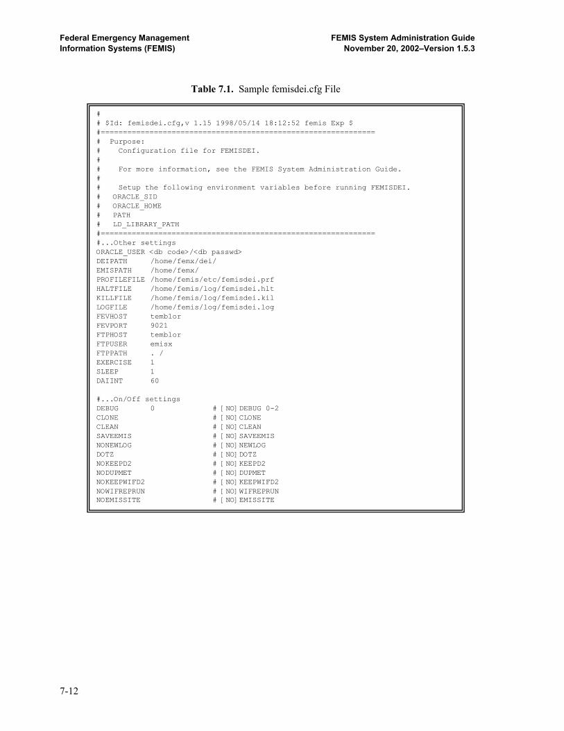
Federal Emergency Management FEMIS System Administration Guide Information Systems (FEMIS) November 20, 2002–Version 1.5.3
Table 7.1. Sample femisdei.cfg File
# # $Id: femisdei.cfg,v 1.15 1998/05/14 18:12:52 femis Exp $ #============================================================== # Purpose: # Configuration file for FEMISDEI. # # For more information, see the FEMIS System Administration Guide. # # Setup the following environment variables before running FEMISDEI. # ORACLE_SID # ORACLE_HOME # PATH # LD_LIBRARY_PATH #============================================================== #...Other settings ORACLE_USER <db code>/<db passwd> DEIPATH /home/femx/dei/ EMISPATH /home/femx/ PROFILEFILE /home/femis/etc/femisdei.prf HALTFILE /home/femis/log/femisdei.hlt KILLFILE /home/femis/log/femisdei.kil LOGFILE /home/femis/log/femisdei.log FEVHOST temblor FEVPORT 9021 FTPHOST temblor FTPUSER emisx FTPPATH . / EXERCISE 1 SLEEP 1 DAIINT 60 #...On/Off settings DEBUG 0 # [NO]DEBUG 0-2 CLONE # [NO]CLONE CLEAN # [NO]CLEAN SAVEEMIS # [NO]SAVEEMIS NONEWLOG # [NO]NEWLOG DOTZ # [NO]DOTZ NOKEEPD2 # [NO]KEEPD2 NODUPMET # [NO]DUPMET NOKEEPWIFD2 # [NO]KEEPWIFD2 NOWIFREPRUN # [NO]WIFREPRUN NOEMISSITE # [NO]EMISSITE
7-12

Federal Emergency Management FEMIS System Administration Guide Information Systems (FEMIS) November 20, 2002–Version 1.5.3
7-13
Table 7.2. femisdei Command Line Options
Use: femisdei <options>... -I <config file> : configuration file name -0 : zero pass (just show settings) -v : show version of FEMISDEI -V : show RCS version of FEMISDEI -help : show help messages -halt : halt other version of femisdei -kill : kill other version of femisdei -purge : delete saved files from/to EMIS -[no]keepd2 : keep vs. delete existing D2PC cases [keep D2] -[no]keepwifd2 : keep vs. delete exiting “what if” D2PC case -[no]wifreprun : allow “what if” cases to replace “run” cases -[no]dupmet : duplicate Met in both exercise and real -[no]dotz : convert times to GMT [convert to GMT] -[no]onepass : one pass (process one file) [multi-pass] -[no]clone : clone a background process [do not clone] -[no]clean : cleanup temporary files [do not cleanup] -[no]saveemis : save EMIS files [do not save] -[no]emissite : use EMIS site codes [do not] -[no]newlog : create new log [append to log] -[no]log <log file> : name of log file [no log file (screen)] -[no]debug <level> : debug level (0,1,2) [no debug] -sleep <seconds> : number of seconds to sleep -daiint <num sleep iter> : num sleep iterations between DAI checks -exercise <number> : exercise number -ep <emis path> : directory for incoming EMIS files -pf <profile file> : profile file name -fev <host> <port> : fev host port -ftp <host> <user> <path> : ftp host username path -dei <dei path> : top-level directory for DEI output files -ora <user/pass> : Oracle username and password

8.0 FEMIS GIS Database The FEMIS spatial data resides on the UNIX server and on each PC that is running FEMIS. The master copy of the spatial database resides on the server and contains the static GIS themes; the unloaded FEMIS ArcView GIS project file (FEMISGIS.APR); an ArcView project file containing several GIS utilities (FEMISGIS_UTILITIES.APR); small, medium, and large versions of the GIS initialization file (FGIS_SM.INI, FGIS_MD.INI, FGIS_LG.INI); two map symbol files (MARKERDF.AVP and OBJ_TYPE.LUT); and several bitmap (.BMP) files that provide images for special-purpose buttons on the custom ArcView GIS interface. When FEMIS is first installed on each PC, the spatial database files for the relevant CSEPP hazard site are copied from the server to the GIS root directory (usually \FEMIS\GIS\<SITE CODE>) and associated subdirectories on the PC. During subsequent FEMIS version upgrades, selected spatial data files may be copied to a PC as necessary to apply changes or additions to the spatial data. The following paragraphs discuss the components of the spatial database and the methods used to maintain, configure, customize, backup, and troubleshoot the spatial database.
8.1 Spatial Data Description The FEMIS spatial database is made up of a number of themes or layers. Each theme contains data (location information and descriptive attributes) representing a collection of geographic objects of a particular type (e.g., roads, political boundaries, meteorological towers, and emergency planning zones). The spatial database also contains a customized ArcView GIS project file, an initialization file that tells ArcView GIS what themes are to be loaded into the project file and how to display them, and an optional legend file associated with each theme that provides additional information on how to display the theme’s data on the map. For detailed descriptions of the individual FEMIS spatial data themes, see Section 3.3, Building Spatial Data, in the Data Management Guide for FEMIS Version 1.5.3.
8.2 Spatial Data Maintenance The static spatial data themes are built from various data sources. These themes normally change infrequently, and such changes are made either by regenerating the entire theme from new or updated data sources or by making minor editing changes in the existing theme data. For detailed information on how to maintain or upgrade the static data themes, see Section 5.0, Managing Spatial Data, in the Data Management Guide for FEMIS Version 1.5.3. As FEMIS is being run, the data in the relational database that corresponds to the dynamic spatial data themes (e.g., facilities) may be altered by users that have the appropriate FEMIS privileges. As necessary during its operation, FEMIS automatically regenerates the spatial data files for these
8-1

Federal Emergency Management FEMIS System Administration Guide Information Systems (FEMIS) November 20, 2002–Version 1.5.3
dynamic themes on each PC based on the current data in the relational database. No additional action by your System or Database Administrator is necessary to maintain these themes under normal circumstances.
8.3 GIS Utilities The GIS Utilities are a set of utilities for System Administrators to use to update GIS information. The GIS Utilities will load the GIS static and dynamic themes in the View when opened. To make sure that the latest dynamic themes information is updated, log into FEMIS, and open the GIS. After the dynamic themes have loaded, close the GIS, and leave FEMIS open. Be sure FEMIS is still open before starting the GIS Utilities. You will be prompted to login to your EOC’s database. 8.3.1 Loading the GIS Utilities A copy of the GIS Utilities ArcView Project file (FEMISGIS_UTILITIES.APR) is stored in the /home/femis/gis directory on your server. To get a local copy of the GIS Utilities on your PC, perform the following: 1. Map the I:\ drive on the PC to the server’s /home/femis directory. Connect to the drive as the
user femis.
2. Open FEMIS v1.5.3.
3. Log in as a user with full GIS privileges.
4. Select Operations Mode. Click OK.
5. Open the GIS. Wait for the themes to fully load.
6. Close the GIS. Leave FEMIS open.
7. Open the GIS Utilities on the PC by double clicking on the I:\GIS\FEMISGIS_UTILITIES.APR file using Windows Explorer.
8. Verify the themes have finished loading, and then save the file as FEMISGIS_UTILITIES.APR in your local GIS directory. Replace the file if it exists.
9. Click OK at the prompt that the FEMISGIS_UTILITIES.APR has successfully loaded with themes.
10. Select the Local EOC Code at the database login window, and click OK.
8-2
Federal Emergency Management FEMIS System Administration Guide Information Systems (FEMIS) November 20, 2002–Version 1.5.3
11. Login at the ODBC Login prompt with the Database user name (<Application Schema>a) and password. Click OK.
8.3.2 Opening the GIS Utilities If the GIS Utilities have not been loaded on this PC, load and save the GIS Utilities by performing the steps in Section 8.3.1, Loading the GIS Utilities. 1. Open FEMIS v1.5.3.
2. Log in as a user with full GIS privileges.
3. Select Operations Mode. Click OK. Do not open the GIS. If the GIS opens, close it.
4. Open the local copy of the GIS Utilities on the PC by double clicking on the
FEMISGIS_UTILITIES.APR file in the local GIS directory using Windows Explorer.
5. Select the Local EOC Code at the database login window, and click OK.
6. Login at the ODBC Login prompt with the Database user name (<Application Schema>a) and password. Click OK.
8.4 Zone Editor The FEMIS Zone Editor allows the user to update the CSEPP Emergency Zones theme or any hazard map layer (GIS zone theme). Zone editing functionality exists in the GIS Utilities and assists the experienced System Administrator to modify the EOC’s Emergency Zones themes. The zone themes are not dynamic themes and should not be modified frequently. The term GIS Zone theme is used to describe any polygonal GIS theme that is defined in the relational database as a Hazard Zone Map Layer, i.e., a theme that contains the boundaries of areas used to define emergency planning zones for one or more specific potential hazards. Such themes include the CSEPP emergency zones theme and can also include a county boundaries theme, a township boundaries theme, or any other polygonal theme. Changes can only be made to a GIS Zone theme at the EOC where it is owned (e.g., a site’s CSEPP Emergency Zones theme is owned by the depot.) The process for updating a GIS Zone theme consists of three major steps: 1. On a FEMIS PC, use the Zone Editor functions in the GIS Utilities to make changes to the GIS
Zone theme boundaries and/or attributes, save the edited theme files, and create a set of text files that capture these changes (see Section 8.4.1, Editing the Zone Theme).
8-3
Federal Emergency Management FEMIS System Administration Guide Information Systems (FEMIS) November 20, 2002–Version 1.5.3
2. On the EOC’s UNIX server, run a script that reads the text files created by the GIS Zone Editor and applies the changes to the FEMIS Oracle database (see Section 8.4.2, Updating the FEMIS Database).
3. Distribute the updated GIS Zone theme files to all FEMIS PCs at the site (see Section 8.4.3, Distributing the New GIS Zone File).
Note: Additions or deletions of zones or changes to the boundaries of existing zones could
make existing Risk Areas invalid. It may be desirable to identify existing Risk Areas that include changed zones, delete these Risk Areas from the database, and then re-create and save new Risk Areas as needed after the zone changes are in place.
8.4.1 Editing the Zone Theme To edit zone themes, complete the following steps. Step 1: Open the GIS Utilities If the GIS Utilities have not been loaded on this PC, load and save the GIS Utilities by performing the steps in Section 8.3.1, Loading the GIS Utilities. Open the GIS Utilities by performing the steps in Section 8.3.2, Opening the GIS Utilities. Ensure you have GIS Full Access privileges. Log in to FEMIS. Do not open the FEMIS GIS while performing the Zone Editing operations, as there may be problems with file sharing. Step 2: Start Zone Editing To start the zone editing process, select Zone Editor Start Zone Editing from the GIS menu. An editable copy of the Zone theme named NEWZONES.SHP will open in the GIS View. If an EOC has more than one GIS Zone theme, you will be prompted to select the theme to edit before the NEWZONES.SHP file opens. If the NEWZONES.SHP file exists from a previous session, it will be opened in the View. If you do not wish to use the NEWZONES.SHP theme from a previous Zone Editing session, close the GIS Utilities, delete the NEWZONES.SHP files, and reopen the GIS Utilities. All edits will be made to the NEWZONES.SHP theme to preserve the original GIS Zone theme until the Zone Editing process is complete. Step 3: Edit the NewZones.shp Theme You will be prompted to make the NEWZONES.SHP theme editable by activating the theme, then selecting Theme Start Editing. Edit the NEWZONES.SHP theme's spatial features and attributes using standard ArcView GIS editing functionality. See the FEMIS Help topic GIS - Edit Polygon for additional instructions on ArcView theme editing. Zone Editing sessions may be stopped and restarted at a later time.
8-4
Federal Emergency Management FEMIS System Administration Guide Information Systems (FEMIS) November 20, 2002–Version 1.5.3
Step 4: Change Zone Attributes The Change Zone Attributes option lets the user modify the zone name and type for all selected zones. You may repeat the operation several times, if needed. The name and ID changes are immediate. If you make an error, you can repeat the operation with the correct information. If necessary, you can delete the NEWZONES.SHP file and begin again. Select one or more Zones for which you wish to modify the name and/or type, and select Change Zone Attributes from the Zone Editor menu. All new Zones must have attributes added. Step 5: Stop Zone Editing When you are done editing the NEWZONES.SHP theme, Select Stop Zone Editing from the Zone Editor menu. You will be prompted to end the editing session on the NEWZONES.SHP theme by activating the theme, then select Theme Stop Editing. This option ends the editing session and creates the input files needed to promote the changes to the database as described in Section 8.4.2, Updating the FEMIS Database. The files created are ZONENAMECHANGES.TXT, ZONETYPECHANGES.TXT, LAYERDEF.TXT, and FACWITHZONECHANGES.TXT. These files will be written in the GIS home directory (specified as the GISTopDirPC in the FEMIS.INI file). The option creates the files by comparing the old and new zone shape files and writing the changes to the files. Before performing any comparisons, this option checks whether the zone IDs and names are unique. If not, the user will be notified and no comparisons will be performed. The user will need to return to Steps 2 or 3 to make zone names and IDs unique. The format of the ZONETYPECHANGES.TXT is as follows: |ID|old_type|new_type|class_id|subclass_id There will be one record in the ZONETYPECHANGES.TXT file for each renamed or added zone. Renamed zones will have all fields. The old_type may be the same as the new type if there was only a zone name change. New zones have a null old_type and the appropriate zone type in the new_type field. The format of the ZONENAMECHANGES.TXT is as follows: |ID|old_name|new_name|zone_type|class_id|subclass_id|zone_num|eoc_name|
8-5
Federal Emergency Management FEMIS System Administration Guide Information Systems (FEMIS) November 20, 2002–Version 1.5.3
There will be one record in the ZONENAMECHANGES.TXT file for each deleted, renamed, or added zone. Except as noted below, none of the fields should contain null values. • Deleted zones will appear as the first records in the ZONENAMECHANGES.TXT file. For deleted
zones, the new_name is null. The deleted IDs will not be listed in the Type file. • Renamed zones records will follow the deleted zone information in the text file. For name
changes, the record lists the zone ID, the old zone name, new zone name, and zone type. • New zones will list the zone number, a null old_name, and the EOC name with primary
responsibility for the zone. The format of the FACWITHZONECHANGES.TXT file is as follows: |facility_name|eoc_name|old__zone_name|new_zone_name|
The file contains a record for every facility that has been affected by the zone changes. • If a facility used to be inside a zone’s boundary but now falls outside all zone boundaries, then
the new_zone_name will be set to null.
• If a facility used to be outside all zone boundaries but is now within a zone, then the old_zone_name will be null.
• If a zone boundary change changes the zone in which a facility is located, then all fields will contain data.
The format of the LAYERDEF.TXT is as follows: |layer_name|eoc_code|exercise_num|
The number of changed records and the list of changes are also reported to the user in an interactive message. Step 6: <<Optional>> Generate Facility Data for Exercises Exercise data may be retained by creating Facility-In-Zone reports for each Exercise. Otherwise, the Exercises will have to be deleted and recreated to reflect the Zone Edit updates.
Note: Make sure that your facility theme data is current by closing the GIS Utilities, opening the GIS from FEMIS, and switching to each Exercise before creating the Facility-In-Zone reports. The facility data will automatically update the themes with the most current data from the FEMIS database as the themes regenerate. Repeat for each Exercise that you wish to update with the new zone edit changes, and then reopen the GIS Utilities.
8-6

Federal Emergency Management FEMIS System Administration Guide Information Systems (FEMIS) November 20, 2002–Version 1.5.3
For each Exercise, select an Exercise, and select Zone Editor Facility Report for Exercise Data. A Facility-In-Zone report will be generated with the Exercise number included in the filename (e.g., FacWithZoneChanges0.txt). Repeat for each Exercise that you wish to update with the new zone edit changes. Step 7: Examine the Text Files and Make Corrections Where Necessary It is essential that the .TXT files are correct to avoid corrupting the Oracle database. Review the files using a text editor to make sure the following conditions are met. Ensure that each file ends with a carriage return. Null values are not allowed in the first field (ID) in any of these files. The other parameters must be compatible with the format of the fields in the database. For example, for zone name changes, the old_name and new_name must be 30 characters or less and must begin with an alpha character. For the ZONETYPECHANGES.TXT file, nulls are only allowed for the following condition. All other nulls should be replaced with the appropriate information. • old_type is null for new zones. For the ZONENAMECHANGES.TXT file, nulls are only allowed for the following conditions. All other nulls should be replaced with the appropriate information. • old_zone_name is null for new zone records.
• new_zone_name is null for deleted zones.
• zone_type may be null for deleted zones.
• Class_id and Subclass_id may be null for renamed zones and deleted zones.
• eoc_name may be null for renamed or deleted zones. Ensure it is the eoc_name rather than the
eoc_code. For the FACWITHZONECHANGES.TXT file, ensure there are no null fields and that the eoc_name field contains the eoc_name rather than the eoc_code. (In certain cases, the GIS cannot determine the eoc_name, so inserts the eoc_code instead.) Use the editor to replace the eoc_code with the eoc_name.
8-7

Federal Emergency Management FEMIS System Administration Guide Information Systems (FEMIS) November 20, 2002–Version 1.5.3
8.4.2 Updating the FEMIS Database When the GIS zone editing has been completed, follow the steps below on the UNIX server to update the FEMIS database. The steps assume the user is familiar with text editing and updating the Oracle database and using SQL scripts. If you intend to save several of the exercises in the database, special considerations apply. In general, always follow the steps below to update the operational data first. After this is successful, then the steps can be rerun for each exercise. 1. Ensure the /home/femis/database/zonedt directory exists. If zone editing has been done
before, the directory will exist; you may want to rename or move the existing *.txt and *.sql files to preserve the previously edited files. If this directory does not exist, create it.
2. Move the four output files created in Section 8.4.1 Editing the Zone Theme, from the PC to the
UNIX server into the /home/femis/database/zonedt directory. Copy the zone_edit_db.sh file from the /home/femis/database/dba directory to the /home/femis/database/zonedt directory. After copying the file, verify that the file contains “execute” privileges. Change the file privileges if necessary.
3. Execute the UNIX shell script named zone_edit_db.sh. The script will check on environment
variables and for the presence of the eoclist.dat and eocnum.dat files in the /home/femis/etc directory.
If all conditions are met, the script will read the four *.txt input files and produce one output file, which contains the actual SQL script to modify the database. The output file is named zone_edit_change.sql. Review this file to ensure all changes have been included by comparing it to the *.txt files.
4. Verify that you know all of the Oracle EOC database passwords, and reset them to the default
values if required. See Section 11.2.2, Modifications to the Manage Database Passwords Tool, for instructions.
5. Test the database changes by running the output script using the SQL*Plus tool. The script will
ask the user to enter 0 the first time it is run or if there are any errors. You should enter 0 at each prompt to make sure the entire set of database changes are correct. To do this step, login to UNIX as femis, move to the zonedt directory, start sqlplus, and run the script as follows: % su – femis % cd /home/femis/database/zonedt % sqlplus /nologin SQL> @zone_edit_change.sql SQL> {a series of outputs will be displayed, look for any errors} SQL> exit >
8-8

Federal Emergency Management FEMIS System Administration Guide Information Systems (FEMIS) November 20, 2002–Version 1.5.3
6. Repeat the process when Step 5 runs without errors, but this time enter 1 at the prompts to commit the changes to the database.
7. Reset the Oracle database passwords to their more secure values, if they were modified in Step 4,
Change Zone Attributes. See Section 11.2.2, Modifications to the Manage Database Passwords Tool, for instructions.
8.4.3 Distributing the New Zone File To complete the zone editing process, complete the following steps: 1. Rename or delete the original zone theme shape files (e.g., <0sitecode>_ez.{shp,shx,dbf}).
2. Rename the NewZones.{shp,shx,dbf} shape files to the corresponding names of the original
zone theme shape files.
3. Copy the new shape files to the GIS directory of all the PCs in all EOCs, replacing the original shape files. The FUPDATE utility, described in Section 14.2, FUPDATE.BAT, may be used.
The zone shape files on the master copy of the spatial database, which resides on the server, must be replaced so future FEMIS installations will use the updated zone theme files.
8.5 General Hazard Theme (GIS Zone Theme) Definition Adding a new GIS Zone theme for use in general hazards modifies an existing polygonal theme to have the required properties of a GIS Zone theme so the polygons can be added as “emergency zones” in the database. You will use the GIS Utilities (FEMISGIS_UTILITES.APR) to add a new General Hazard theme. No privileges are needed to access Add New General Hazard Theme, but you must have file write privileges to overwrite the theme files.
Note: If the polygonal theme does not exist in the GIS, it must be added via the GIS Configuration Editor.
8.5.1 Adding a New General Hazard Theme To add a new general hazard theme, complete the following: 1. Select a polygonal theme by clicking on the theme legend in the GIS Utilities. The theme shows
that it is selected when the legend appears to be raised.
8-9

Federal Emergency Management FEMIS System Administration Guide Information Systems (FEMIS) November 20, 2002–Version 1.5.3
Note: Inspect the polygonal theme to verify that it is not already in General Hazard/GIS Zone Theme format. This can be done by selecting the theme and clicking the Open Theme Table button (grid/spreadsheet symbol).
Look for the following sequence of attributes (column names) in the theme table: Shape, Zone_id, Zone, Type, Par_pad, Risk_area, Objectname, Objecttype, Objectid, and EOC_name. If all of these attributes are present, then the theme is in the proper format to be used as a General Hazard/GIS Zone theme, and you do not need to complete the remaining steps in this section.
2. Open the GIS Utilities (FEMISGIS_UTILITES.APR) and select General Hazard Add New
General Hazard Theme. You will be asked if you wish to continue with the selected theme. Click Yes to continue.
3. Select a unique name field. FEMIS requires that all zones of the same polygonal theme have
unique names. If you are unsure, click the Cancel button, find a field that you wish to use as the name field, make sure all of the names are unique, and start again. If some of the names are not unique, select another field or use ArcView theme editing capabilities to rename the polygons.
4. Enter a Type for each polygon. The theme will have one or more Types.
For example, if a county theme is being used, the type may be WA for all the counties in Washington and OR for all the counties in Oregon. Each type can have a unique GIS symbol.
5. Enter the EOC that administers the polygon from the drop-down list. Each polygon will have an
EOC that makes protective action decisions for the polygon to indicate what protective actions it will perform in case of an event.
For example, a county could be administered by its own county’s EOC, a neighboring county’s EOC, or by the state EOC. A township could be administered by the county that it resides in, or by the state EOC.
You will be prompted to repeat Steps 4 and 5 for each polygon. When you are done, you will need to create the General Hazard Database Reports. 8.5.2 General Hazard Database Reports Creating General Hazard Database Reports creates the report files needed to add a theme’s polygons as emergency zones in the database. You will use the GIS Utilities (FEMISGIS_UTILITES.APR) to create the General Hazard Database Reports.
8-10
Federal Emergency Management FEMIS System Administration Guide Information Systems (FEMIS) November 20, 2002–Version 1.5.3
Note: A theme must be in General Hazard format. To create a theme in General Hazard format, see Section 8.5.1, Adding a New General Hazard Theme.
Four text files will be generated for the FEMIS database processing:
hazard_parameters.txt hazard_subtype.txt hazard.txt facwithzonechanges.txt
To create the General Hazard Database Reports: 1. Open the GIS Utilities. Select the polygonal theme in General Hazard format by clicking on the
theme legend in the GIS Utilities. The theme shows that it is selected when the legend appears to be raised. You must select only one polygonal theme at a time.
2. Select General Hazard Create General Hazard Database Reports. You will be
prompted to continue or quit. Click Yes to continue. General Hazard Theme Parameters Report (hazard_parameters.txt) This report contains information on the theme and the owner of the layer. Much of the information will be pre-populated based on the system’s best guess. Edit the fields as desired.
GIS Layer Name: A short name describing the theme. This name must be a unique GIS layer name in the FEMIS database.
GIS Legend Name: Text description visible in the GIS legend. GIS Layer Description: Long description of the theme and its contents. Hazard Zone Flag: Must be Y. Not editable. Location Type: Object type (category) of spatial data. Must match the Object
Lookup Category column in the FEMISGIS.INI file for this theme. EOC Name: Official EOC Name of the EOC that owns and created the theme.
Not editable.
General Hazard Theme Subtype Report This report contains information on the zone Types and prompts the user for a detailed description of the zone Types.
Zone Description: Long description for each type.
8.5.3 Modifying General Hazard Theme Display Attributes Once a theme has been modified to be a GIS Zone Theme, the theme must be set up to display correctly.
8-11

Federal Emergency Management FEMIS System Administration Guide Information Systems (FEMIS) November 20, 2002–Version 1.5.3
If the new GIS Zone theme did not previously exist in FEMIS, it must be added to the FEMISGIS.INI file and the OBJ_TYPE.LUT file. If it is an existing theme, then the existing entries in the FEMISGIS.INI file and OBJ_TYPE.LUT file should be modified. Both of these modifications can be done from the GIS Configuration Editor. 1. Close the GIS Utilities.
2. Open FEMIS.
3. Log in as a user with full GIS privileges.
4. Open the GIS.
5. Open the GIS Configuration Editor.
6. Click the Add button for a new theme or Details for an existing theme on the GIS Configuration
Editor window. Theme Tab
Theme Name: This will be the theme name FEMIS reads and must match the database entry (GIS_Layer_Name) for this theme.
Legend Name: This will be the theme name the user sees. Theme Type: Select Polygon. FEMIS Access: Select Yes. Object Category: This must be the Location Type as defined in the General Hazard Theme
Parameters Report. Examine the hazard_parameters.txt file if necessary. Classification: Objecttype. Label Field: Objectname. Default Legend: Classified. Relative Path: This is the path relative to the FEMIS GIS directory of where the new GIS
Zone theme will be located when it is installed on all PCs. Load Theme: Yes. Click the Map Select button to select a default line and polygon fill pattern.
Legend Symbol Tab
For each GIS Zone Type defined in the General Hazard Theme Subtype Report, enter the GIS Zone Type and define a polygon line and fill pattern by pressing the Map Select button. Click OK to close the GIS Configuration Editor Details window. The changes will be saved to the Symbol Lookup file (/lookup/obj_type.lut).
8-12
Federal Emergency Management FEMIS System Administration Guide Information Systems (FEMIS) November 20, 2002–Version 1.5.3
8.5.4 Distributing the New GIS FEMISGIS.INI and Symbol Lookup Changes
In order for all users to use the new GIS Zone Theme, the modifications to the FEMISGIS.INI file and the Symbol Lookup Table (/lookup/obj_type.lut) must be updated on the server and distributed to the users. The new/modified line in the FEMISGIS.INI file should be saved to all versions of the FEMISGIS.INI file on the server. The updates can be made with a text editor. The files are
/home/femis/gis/<site code>_apr/fgis_lg.ini /home/femis/gis/<site code>_apr/fgis_md.ini /home/femis/gis/<site code>_apr/fgis_sm.ini
The modified Symbol Lookup table can be updated on the server by replacing the server's obj_type.lut file with the modified file on the local PC. The file can be found at
/home/femis/gis/<site code>/lookup/obj_type.lut
To distribute the new GIS zone theme, follow the steps in Section 8.4.3, Distributing the New Zone File.
8.6 GIS Configuration When you install FEMIS using the full GIS installation option, the complete GIS directory structure and all data files referenced by the selected FEMISGIS.INI file (see the following paragraph) are copied from the server to the \FEMIS\GIS\<SITE CODE> directory and associated subdirectories on your PC. This may take several minutes, depending on the volume of data to be copied for your site and the speed of the network. You will be given an option to choose from among several versions of the FEMISGIS.INI file. The FEMISGIS.INI file specifies primarily the spatial themes that are to be installed and used to build the operational ArcView GIS APR file for use with FEMIS. For most CSEPP sites, the three choices available are small, medium, and large. A small or minimum FEMISGIS.INI file installs only the theme files that are essential for running FEMIS (e.g., zone boundaries, igloos, and facilities) or to provide a minimum map background for location reference (e.g., state and county boundaries, major roads, and populated place names). The medium size FEMISGIS.INI file includes most of the themes but does not include large image files and other large nonessential themes (e.g., contour lines and streams). A large, or maximum, FEMISGIS.INI file installs all of the currently available GIS themes for the site.
8-13

Federal Emergency Management FEMIS System Administration Guide Information Systems (FEMIS) November 20, 2002–Version 1.5.3
To have the most complete GIS, choose the largest FEMISGIS.INI option that will comfortably fit within the available memory space on your hard drive. However, additional themes may negatively impact the speed of GIS response. The setup program will provide information on the space required to install each option and the amount of space available on your hard drive. To create a custom GIS configuration that is different from any of the three optional predefined configurations (FEMISGIS.INI files), you will need to copy the largest FEMISGIS.INI file to your PC and then edit it according to the instructions in Section 8.7, Customizing the FEMIS Map. Upon completion of the GIS data installation, the \FEMIS\GIS directory will contain the FEMPTY.APR and one or more <SITE CODE> subdirectories. Each \FEMIS\GIS\<SITE CODE> directory will contain a number of subdirectories, each subdirectory containing the data files for one or more specific themes. The main \FEMIS\GIS\<SITE CODE> directory will also contain the FEMISGIS.APR and FEMISGIS.INI files. A special subdirectory, \FEMIS\GIS\<SITE CODE>\LOOKUP, contains several bitmap (.BMP) files that provide images for special-purpose buttons on the custom ArcView GIS window, and two symbol files (MARKERDF.AVP and OBJ_TYPE.LUT) that include information used to generate the theme classification legends. These legends are used to display different map symbols or icons based on the value of a designated attribute within a GIS theme. For example, facilities can be assigned symbols based on the facility type, such as schools or hospitals. The following section discusses methods you can use to modify symbols in the default symbol lookup table, add new symbols to this table, and change the assignment of symbols to classes of attributes (e.g., facility types) in the FEMIS spatial themes. 8.6.1 Symbol Lookup Table The symbol lookup table is located in the <GIS INSTALL DRIVE>\FEMIS\GIS\<SITE CODE>\LOOKUP directory under the file name OBJ_TYPE.LUT. The lookup table specifies the symbols to be used to create the theme legends. Each line consists of seven entries separated by vertical bars as delimiters. Lines that begin with a single quote are comment lines and will be ignored by FEMIS. Blank lines are also ignored. The first five fields are numbers corresponding to a symbol type, color, size, background color, and outline color. These numbers reference symbol attributes from within the active symbol palettes in ArcView GIS. The fourth and fifth fields are only used in polygonal themes. The sixth entry specifies the theme type or object category, and the last entry specifies the theme subtype or classification label. The symbol type and color numbers designate the order in which the symbols are listed in the FEMIS GIS palette window using 0 for the first element. The symbol size is measured in points (1/72 of an inch). In polygonal themes, the “size” number is used to set the outline width. If the classification label is missing, it should be set to none. An example of the lookup table is listed below. From the facility entries, we can see that school facilities are represented with the 89th symbol, colored with the 46th color, and measure 12/72 of an inch. To customize the lookup table, use the GIS Configuration Editor (see Section 8.7.3) or edit the file using a text editor.
8-14

Federal Emergency Management FEMIS System Administration Guide Information Systems (FEMIS) November 20, 2002–Version 1.5.3
'Symbol | Foreground |Symbol | Background | Outline | Object | Classification 'number | color | size | Color | Color | Category | Label 6 | 16 | 2 | 0 | 14 | zone | Depot 7 | 16 | 2 | 0 | 14 | zone | IRZ 9 | 16 | 2 | 0 | 14 | zone | PAZ 8 | 1 | 2 | 0 | 4 | county | OR 8 | 1 | 2 | 0 | 44 | county | WA 0 | 8 | 2 | | | road | Primary 0 | 8 | 1 | | | road | Secondary 1 | 7 | 1 | | | road | Local . . .
26 | 46 | 10 | | | tcp | Access 26 | 51 | 10 | | | tcp | Traffic 26 | 50 | 10 | | | tcp | Traffic/Access
26 | 51 | 10 | | | tcp | #NULL# . . .
125 | 51 | 10 | | |facility |airport 89 | 46 | 12 | | |facility |school 96 | 46 | 14 | | |facility |shelter . . .
8.6.2 Symbol Defaults The MARKERDF.AVP file contains the symbols loaded in the default FEMIS symbol palette. You may change these symbols using the generic ArcView GIS palette window functionality. You may use any of the other symbols provided by ArcView GIS in the C:\ESRI\AV_GIS30\ARCVIEW\SYMBOLS directory. You may also import symbols from ARC/INFO or icons in raster format. If you delete or change the sequence of the existing symbols, then some of the FEMIS GIS “look and feel” will change. For example, if you change the 42nd symbol from a cross hair ( ⊕ ) to an asterisk ( * ), then the object (e.g., facility) locations in the FEMIS GIS will be depicted with an asterisk instead of the familiar cross hair. You may add new symbols at the end of the palette and use the symbol lookup table (Section 8.6.1, Symbol Lookup Table) to refer to the new symbols.
8.7 Customizing the FEMIS Map You can customize the content and appearance of the FEMIS map by editing the original FEMISGIS.INI file or any of the alternate INI files to create a custom FEMISGIS.INI file that can then be used to create a custom APR. The GIS Configuration Editor, described in Section 8.7.3, can help you edit the FEMISGIS.INI file and the lookup table. You can add new themes; delete existing themes; change the minimum or maximum scale display thresholds; modify the type, color, and size
8-15

Federal Emergency Management FEMIS System Administration Guide Information Systems (FEMIS) November 20, 2002–Version 1.5.3
of line or point map features; change the legend names; designate the label (and if applicable, classification fields); specify the default classification fields; designate an alternative directory (and if needed, an alternate drive) for the data source of non-point themes; and control which themes are visible by default when the GIS is first started. A detailed description of the fields in the FEMISGIS.INI file is in Section 8.7.1, Customizing the FEMISGIS.INI File. You can also import your own symbols from other ArcView GIS, ARC/INFO, or raster icons by changing the symbol lookup table and the FEMIS default palette as described in Section 8.6.1, Symbol Lookup Table. If you customize your FEMIS map, please keep track of the changes to ensure they can be retained during future FEMIS or GIS upgrades. 8.7.1 Customizing the FEMISGIS.INI File The FEMISGIS.INI file contains data required to initialize GIS parameters that generate the FEMISGIS.APR and to ensure proper GIS contents each time the FEMIS GIS is invoked by the FEMIS application. The contents of the FEMISGIS.INI file are discussed below. The FEMISGIS.INI file is automatically updated anytime you define a new dynamic theme or modify an existing one. If you have an abnormal termination of FEMIS or the GIS, the dynamic themes section of the FEMISGIS.INI file may be corrupted. To restore the file, you can delete all of the theme entries below the facilities theme. These entries are for the user-defined themes, and they will be regenerated the next time you start FEMIS. Blank lines are ignored in the FEMISGIS.INI. Lines with a single quote in the first column are recognized as comment lines and are ignored. Vertical bars ( | ) delimit the data fields in the FEMISGIS.INI. No data value should contain a vertical bar. String values do not need to be quoted. The [FEMIS_VERSION] section specifies the FEMIS version for which this .INI file can be used. The next line specifies the size of the themes in the current .INI file. Valid size values are small, medium, or large. The [SITE_CODE] section specifies the CSEPP site code that the GIS data describes. This parameter should be identical to the corresponding site code in the FEMIS.INI file; otherwise the GIS will not work. The [DEFAULT_HAZARD_THEME] specifies the theme that is to be used as the “zone” theme for the default hazard (normally CSEPP). Zone themes within FEMIS are used to create Risk Areas and Protective Action Decisions. Each hazard that is defined in FEMIS has a zone theme specified for use with that hazard. The [PROJECTION_PARAMETERS] section specifies the UTM (Universal Transverse Mercator) projection and coordinate system parameters required for the site. The parameters shown in the example are for UTM Zone 16 (appropriate for the Anniston, Alabama site).
8-16

Federal Emergency Management FEMIS System Administration Guide Information Systems (FEMIS) November 20, 2002–Version 1.5.3
The [AREA_OF_INTEREST] section specifies a geographic area of interest. The area of interest for FEMIS has been set as a rectangle that starts at the origin (lower left corner) of -126.00 degrees longitude, 23.00 degrees latitude, spans 58 degrees longitude (first size parameter), and 27 degrees latitude (second size parameter). This covers the continental United States. The area of interest is specified to minimize the consequences of ill-defined data points. In certain circumstances, the user is given the opportunity to define the longitude and latitude where an event has occurred. The FEMIS GIS does not allow the specification of plumes or threat wedges that originate outside the area of interest. The theme description sections specify the configuration for the themes to be loaded in the FEMIS GIS. The two sections are [STATIC_THEMES] and [DYNAMIC_THEMES]. Dynamic themes are those themes that can be completely regenerated from information in the FEMIS Oracle database. Parameters for each theme are discussed below. The same information is included as comments in the FEMISGIS.INI file itself. It has been omitted from the following example to conserve space. • Theme Name – Indicates the theme (layer) name in the GIS and in the FEMIS database if the
theme is FEMIS accessible.
• FEMIS Accessible – For feature themes, this column contains Yes or No to indicate whether the theme is referenced by the GIS_LAYER database table and can thus be accessed directly by the FEMIS software. If this column contains Yes, the Theme Name column in this line should contain the same name as the corresponding GIS_Layer_Name in the FEMIS Oracle database. For image themes, this column contains the name of an image catalog to be created, or None. If the name of an image catalog is listed, the image catalog must be defined in another theme description line in this .INI file.
• Type – The Type column must contain one of the following valid types: Image, ImgCat, point, line, or polygon.
• Load Flag – This column indicates whether to load the theme (Yes) or not to load the theme (No).
• Visible Flag – Indicates the visibility of the theme when forming the .APR.
• Display Order – Indicates the order in which themes will appear in the GIS Table of Contents. The theme indicated by the smallest Display Order number will appear at the top of the table of contents and will be loaded last (on top of all the other themes). The display order number may be negative.
• Label Field – Indicates the field name to be used as the default labeling field.
• Object Lookup Category – Indicates the FEMIS theme category. The value must be one of the types listed in the \…\LOOKUP\OBJ_TYPE.LUT file. Currently, valid values are zone, county, igloo, facility, tcp, road, and siren. If the value is None, indicating that a classification
8-17
Federal Emergency Management FEMIS System Administration Guide Information Systems (FEMIS) November 20, 2002–Version 1.5.3
legend will not be displayed for the theme, then the classification field should also be set to None and the default legend field should be set to simple.
• Default Legend – Indicates whether a simple or classified legend is used. Valid values are simple, none, and classify. Simple indicates a simple legend that uses one symbol to depict all the theme data. For image themes none is used, for which a classify legend does not apply.
• Classification Field – Indicates the field to be used to classify the legend. If the classified legend file does not exist, it will be created.
• Min Scale – Indicates the minimum scale denominator (1 : Min Scale) at which a theme will be displayed.
• Max Scale – Indicates the maximum scale denominator (1 : Max Scale) at which a theme will be displayed.
• Legend Name – Indicates the name to be used in the theme’s legend in the Table of Contents. • Customize Flag – For dynamic themes, Yes indicates the current symbol parameters listed in
later columns of this record should always be used and should not be overwritten when this dynamic theme is updated. No indicates the symbol parameters in this record should be overwritten with values from the FEMIS Oracle database when this dynamic theme is updated. The Customize Flag does not apply to static themes, so the field should contain N/A for static themes.
• Symbol – Indicates the numeric palette index for the symbol (point icon, line type, or polygon fill pattern) to be used in the theme’s simple legend.
• Color – Indicates the numeric palette index for the foreground color of the theme’s symbol.
• Size – Indicates the symbol size. For linear and polygonal themes, this is the line width.
• Back Color – Indicates the background color for polygonal fill symbols.
• Outline Color – Indicates the outline color of polygonal fill symbols.
• Path – Indicates the relative path of the file for the theme. The relative path is appended to the GIS home directory (root path) as specified in the FEMIS.INI file by the keyword FemisGISTopDirPC.
• Alternate Prefix – Indicates that the theme files for this theme are located relative to a different GIS home directory than the one specified in the FEMIS.INI file. The script that loads the themes appends the relative path to this prefix to locate and read an alternate source directory. This parameter can be used to access data located somewhere other than the default
8-18

Federal Emergency Management FEMIS System Administration Guide Information Systems (FEMIS) November 20, 2002–Version 1.5.3
GIS home directory on your PC hard drive (e.g., on a CD-ROM). Any auxiliary files that FEMIS needs to create (e.g., the theme legend files) will be written using the default GIS home prefix.
8.7.2 Altering the Default FEMIS Map To alter the default appearance of the FEMIS map, use the Use at Startup option for FEMIS GIS ViewMarks (see the FEMIS Help). For more extensive or permanent changes, complete the following steps: 1. Make a backup copy of the original \FEMIS\GIS\<SITE CODE>\FEMISGIS.INI file to a different
directory or to a different file name in the same directory (e.g., FGISORIG.INI) so you can retrieve it and use it later, if necessary. Do the same with the original .APR (e.g., copy it to FGISORIG.APR). Use the GIS Configuration Editor (Section 8.7.3) or manually edit the .INI file:
a) Themes defined by lines in the [STATIC_THEMES] or [DYNAMIC THEMES] sections can be
excluded from loading into the ArcView Project. The preferred method of excluding themes is to change the Load Flag column from YES to NO. Alternatively, you can comment out the line by inserting a single quote as the first character of the line; or, you can simply remove the line.
b) You can add lines to the [STATIC_THEMES] section to define new themes. c) You can modify appropriate parameters of existing themes as desired.
2. Run ArcView GIS using the empty project file, \FEMIS\GIS\FEMPTY.APR, by double clicking on
the file name in the Windows Explorer. When the ArcView Project (.APR) has finished loading, it will contain the FEMIS static themes indicated in the FEMISGIS.INI files. The ArcView Project will be saved to the FEMISGIS.APR file in the GIS home directory. Later, when the FEMIS application loads the FEMISGIS.APR, any changes made to the configuration of the dynamic themes will also be depicted.
3. Examine the theme legends to see that the correct set of static themes are loaded and the correct
ones are visible. The dynamic themes will not appear in the legend at this time. These themes are loaded when FEMIS activates the FEMISGIS.APR. Then examine each theme to see that it displays correctly (check the checkbox in the legend to make visible the themes that are invisible by default). For themes that have both a simple and a classified legend, toggle the legend between both legend types using the Toggle active theme legends button on the GIS tool bar. If some themes are not displayed correctly, recheck the .INI file. If necessary, exit ArcView GIS, edit the .INI file to make corrections, and then repeat Steps 2 and 3.
4. Exit ArcView GIS. The FEMISGIS.INI and FEMISGIS.APR files you just created will be used
each time the GIS is started.
8-19
Federal Emergency Management FEMIS System Administration Guide Information Systems (FEMIS) November 20, 2002–Version 1.5.3
8.7.3 GIS Configuration Editor The GIS Configuration Editor is a stand-alone program that provides an easy to use interface for modifying the FEMISGIS.INI and OBJ_TYPE.LUT files.
Note: Make a backup copy of the FEMISGIS.INI and OBJ_TYPE.LUT files so that you can recover from an unsatisfactory editing session.
The [SITE_CODE], [DEFAULT_HAZARD_THEME], [PROJECTION_PARAMETERS], and [AREA_OF_INTEREST] sections of the FEMISGIS.INI file can be modified on the main window. The [STATIC_THEMES] and [DYNAMIC_THEMES] sections are displayed in a spreadsheet on the main window. Lines with a single quotation mark in the first column are recognized as comment lines and are ignored. To modify an individual spreadsheet entry, select the row and click the Details button or double-click on the row. The GIS will be started and a Details window will be displayed for that row. All the fields are described in Section 8.7.1, Customizing the FEMISGIS.INI File. The symbol parameters for shape, color, and size can be entered using the text boxes or by clicking the Map button and selecting a symbol and color from the palette. The GIS can be used to preview the symbols and determine the appropriate symbol parameters. If the Map button is pressed, the GIS will be brought to the foreground with the ArcView GIS palette active. Use the ArcView GIS palette to modify the color, shape or fill pattern, and size of the drawn symbol. When satisfied with the symbol appearance, click the Pyramid button (Return the Selected Symbol). The appropriate numbers for the symbol’s color, shape or fill pattern, and size will be returned to the Details window. The size is measured in 1/72 of an inch. For lines, it designates width. For polygons, the size is used for the width of the outline. The Legend Symbol tab is used to add, edit, or delete entries from the OBJ_TYPE.LUT file. The symbol parameters for shape, color, and size can be entered by using the text boxes or by clicking the Map button. The GIS can be used to preview the symbols and determine the appropriate symbol parameters. If dynamic themes or the OBJ_TYPE.LUT file have been modified and saved, close the GIS, and restart to implement the changes. For static themes, once the changes have been saved to the FEMISGIS.INI file, follow the instructions found in Section 8.7.2, Altering the Default FEMIS Map, to alter the default FEMIS map. 8.7.4 Theme Projection Utility FEMIS uses theme data that has been projected in UTM coordinate system in order to avoid re-projecting geographic coordinates each time the view is refreshed. To include new themes in
8-20

Federal Emergency Management FEMIS System Administration Guide Information Systems (FEMIS) November 20, 2002–Version 1.5.3
FEMIS, they should be converted to UTM. The Theme Projection Utility converts feature themes in geographic coordinates to UTM coordinates for the desired CSEPP site. Image themes, which are required to be in projected coordinates, are skipped by the Theme Projection Utility. Image themes not already in UTM would need to be projected using other software such as ARC/INFO. When you open PROJECTION_UTILITY.APR, ArcView GIS will start, and a window containing two Views will display. View1 (the work area) is on the left side; and View2 (where the results are depicted) is on the right side. The Theme Projection Utility assumes that the input themes are in geographic coordinates and will let you select and load themes in View1 so they can be exported as projected shape files using the currently specified View1 projection. The projected themes are added to View2. To use the Theme Projection Utility, complete the following steps: 1. Double-click on the PROJECTION_UTILITY.APR (usually located in your C:\FEMIS\GIS
directory). 2. Click View Properties Projection.
3. Select the Standard radio button, and Geographic will display in the Type field.
4. Load the themes you want to project. Click the + (Add Theme) button. 5. Click the Export Projected item under Utilities, and click OK on the brief information
window that displays.
6. Select the desired CSEPP site from the list, and click OK.
7. Make any necessary adjustments to the UTM projection parameters for the selected site, and click OK.
8. Navigate to the desired directory or accept the default (usually C:\TEMP), and click OK.
9. Select the themes you want to export from the list of the themes in View1, and click OK. If the name of the theme being converted already exists in the selected directory, a temporary name will be suggested for the converted theme. Click OK to accept the temporary theme name. The conversion process will start and the status bar will indicate the progress of conversion. The new theme(s) will be loaded in View2 so you can visually verify the results. You may want to load some of your other themes, like raster images, to check how well the projected coordinate match the existing themes.
8-21

Federal Emergency Management FEMIS System Administration Guide Information Systems (FEMIS) November 20, 2002–Version 1.5.3
8-22
10. Click Exit under the File menu to close the PROJECTION_UTILITY.APR file. Click No on the message about saving changes to this file.
8.7.5 Adding Orthophotos Orthophotos can be added to the FEMIS GIS from the GIS Configuration Editor like any other map theme. However, it should be noted that Orthophotos can be extremely large files, and if a large number of files are used, it is recommended that they be in a compressed image format such as compressed TIFF, JPEG, or MrSid. It is also recommended that multiple contiguous image files of the same scale be put in an image catalog to make viewing easier for the user.
8.8 Backup Procedures The installation directory for the spatial data on the UNIX server is /home/femis/gis. The current operational GIS data is copied from this directory and included subdirectories to the PCs when FEMIS is installed or upgraded. It is recommended that a backup copy (tar tape) of this directory be made each time a new version of FEMIS is received. The tape should be labeled FEMIS GIS Data with the date and FEMIS version number included. If the GIS data on the server should become corrupted or deleted, the spatial data can be restored from the backup tar tape without having to perform a reinstallation of FEMIS on the server. If a site or EOC customization of the spatial data and/or the .APR and .INI files is to be done, the original GIS data directory should first be copied to another directory (e.g., /home/femis/data/v<x.y>/gis, where <x.y> is the FEMIS version number associated with the released data). A second tar tape of the GIS directory should be made following the completion of the GIS customization.

9.0 FEMIS Oracle Database Oracle Release v8i, a commercial database management system (DBMS), manages the relational database in FEMIS. The distributed processing features of Oracle are utilized to produce a multi-server distributed data architecture. Data replication is widely used to provide a local copy of most shared tables. This replication is important because it allows an EOC to operate autonomously in case the links to other EOCs are not operational. Also, performance is enhanced because the local tables are located on the local database. The FEMIS relational database is made up of approximately 150 tables. The FEMIS logical data model describes graphically what information is present and how the data objects are interrelated. The model represents a large collection of general-purpose tables, GIS tables, and dispersion tables. Additional information about the data model is available in the Data Management Guide for FEMIS Version 1.5.3. Based on design efforts and testing results, each relational database table is local to an EOC or shared with the other EOCs. Data in the local tables can be accessed only by users logged in to that EOC. The data in shared tables is available to several EOCs. Details of data placement are made transparent to the FEMIS users, so the FEMIS database appears to be a single, unified collection of tables. This physical design of the Oracle database is provided as a part of database implementation and should be applicable to all CSEPP sites. More details about the DBMS are provided in the Data Management Guide for FEMIS Version 1.5.3. For information on the recommended backup strategy and performing Oracle database backups, see Section 12.0, Backup Strategy for FEMIS.
9.1 Data Description When creating the first database for a new site or when making major database modifications, it is necessary to create the database structure from scripts and load basic data so the FEMIS application can operate. For most situations, the new database will be created in a development facility and then packaged so it can be delivered to the operational site. Section 3.0, Building the Initial Information, in the Data Management Guide for FEMIS Version 1.5.3, describes how a new database is installed at the site. For cases where the FEMIS software is updated to a new release, the existing site database can be updated, if necessary, to support new capabilities. In this case, one or more scripts are developed to make the data structure and/or data content modifications. Instead of recreating the database, the scripts are run to make it compatible with the new FEMIS version of software.
9-1
Federal Emergency FEMIS System Administration Guide Information Systems (FEMIS) November 20, 2002–Version 1.5.3
9.2 Replication Oracle provides several ways to share data between EOC servers in a distributed, multiserver environment. When the site environment is not tightly controlled by one group, it makes sense to operate in a mode where operations can proceed in each server independent of what the other servers are doing. To make this happen, data sharing has to be asynchronous so that data changes in one server are not dependent on making similar changes in the other servers in the same transaction. Shared data record changes are propagated to other servers using event driven, push replication built from Oracle’s Replication Management application program interface (API). This method is currently used by FEMIS since it is asynchronous, flexible, and uses much less processing and fewer network resources than the previous replication scheme. The database where the change occurs creates a deferred remote procedure call RPC that is placed in the Deferred Queue. This queue is pushed to remote servers thus causing the RPC to execute and pass the data change parameters. Then the remote server executes a request for the updates. In FEMIS versions before 1.4.5, remote servers polled at a 45-second rate looking for data changes. Due to constant polling, all parts of the system had to be available day and night. The new push replication does not do any work until a data change occurs. This reduces the polling overhead at the remote sites and the request traffic on the network. When the database is installed at a site, either a configuration with all EOCs on a single server or a configuration of several servers is chosen. Single server configurations are used in development and test centers, but all of the CSEPP sites use multi-servers. In the former case, there is no replication since the data is shared by Oracle views. If the multiple server option is used, then scripts delivered with the database are run to create the data sharing objects (see Section 2.9, Creating or Updating the FEMIS Database, in the Installation Guide for FEMIS Version 1.5.3). Once the distributed objects are created, replication can be initiated by running the scripts provided. Before doing this, establish that the other servers at the site are in a ready state to be able to participate in data sharing. If a local site is going to be down for several hours or more, replication can be stopped at the other servers by running the stop scripts.
9.3 Database Maintenance FEMIS has a monitoring tool, called AutoRecovery, that continually checks the status of the EOC’s critical hardware and software components. When failures are detected or thresholds are exceeded, warning messages are sent to the System and Database Administrators. In certain cases, this tool attempts to remedy problems directly. In other cases, the System and Database Administrators must take manual actions to remedy the problems or take measures to correct situations that caused threshold warnings.
9-2
Federal Emergency FEMIS System Administration Guide Information Systems (FEMIS) November 20, 2002–Version 1.5.3
AutoRecovery monitors the portions of the database that are most likely to have problems. In most cases, it tries to warn the Database Administrator before the problem causes a serious failure; this is done by thresholds and looking for symptoms of problems, such as network interruptions. In cases where the problem exists and can be resolved, an immediate fix is attempted. The local database and the database listener are checked each cycle. If the listener is down, a restart is immediately attempted. A database failure is a serious condition that must be analyzed before a restart is attempted since the restart may result in bigger problems. If the database is not functioning, the Database Administrator should look in Oracle’s alert log to determine the cause. If the condition is no longer present or has been fixed, the database can be restarted from a command line sequence as follows:
> su – oracle <If not already logged in as the oracle user> > <pwd> >svrmgrl >connect internal >startup
Section 2.0, FEMIS Monitoring Tools, describes the operation of this AutoRecovery tool and other tools that are available to troubleshoot and repair the database. In the Installation Guide for FEMIS Version 1.5.3, Section 2.13, Installing the FEMIS AutoRecovery System, discusses how to install these tools and configure AutoRecovery to support the site.
9.4 How AutoRecovery Works with the Database AutoRecovery monitors the database tablespaces and warns when the utilization thresholds are exceeded. When these warnings are present for an hour or longer, the Database Administrator should take action to prevent the tablespace from reaching the full (or 100% used) condition that will cause a serious database failure. The common causes of tablespace increase are that more data has been added intentionally or some old data, which is not essential, exists in the database. The Database Administrator should check to see if old data is present and if so, remove it. This will cause the tablespace warnings to cease and have the added benefit of increasing system performance by reducing table sizes. The two most common old data types are meteorological data that has not been archived and extra, nonessential exercises. If the system has recently added new records to the database intentionally, then one or more tablespace sizes should be increased to give a margin for additional growth. If this is necessary, find the name(s) of the data files from the AutoRecovery log and enter the following commands logged in as the UNIX oracle user: >svrmgrl SVRMGR> connect internal SVRMGR> alter database datafile ’<full path of new file>’ resize xxM; SVRMGR> exit
9-3
Federal Emergency FEMIS System Administration Guide Information Systems (FEMIS) November 20, 2002–Version 1.5.3
9-4
A real example to increase the size of the FMAIN datafile to add 100 MB to an existing size of 200 MB is SVRMGR> alter database datafile ’/files2/app/oracle/oradata/fi1/fmain01.dbf’
resize 300M; AutoRecovery monitors remote servers and then sends warnings if problems are seen. If these problems persist beyond a threshold count, a Disable Node command is sent to the database to stop pushing changes to the bad server and also to stop any update processing from the bad node. This will normally prevent the local database from suffering problems. When AutoRecovery can communicate with the disabled node reliably, an Enable Node command is sent to the local database to reestablish replication. Database replication is dependent on all components of the network functioning properly including communications, servers, and database. When some failure occurs, replication may not be able to copy database changes. Oracle has built in error recovery that will keep trying up to 16 times, but if all tries are unsuccessful, Oracle will stop and declare that replication is broken. AutoRecovery monitors local replication processing and will attempt to fix errors when they are detected. There are also sets of fix scripts that can be used to manually correct replication problems. Your Database Administrator should look over these scripts and become familiar with their use. Under normal conditions, AutoRecovery will fix all replication problems.

10.0 Server Network Time Protocol (NTP) Set Up The Network Time Protocol (NTP) executables are included with the Solaris 7 and Solaris 8 operating systems. Scripts in the FEMIS application configure NTP for the UNIX server and Windows. Once NTP has been installed and checked out, all PCs on an EOC’s LAN acquire time synchronization from the NTP service running on the UNIX server for that LAN. Note: The NTP server for a LAN could be located on a different LAN than the PCs. If so,
select the UNIX server closest to the PCs’ LAN. A Network Time Policy needs to have been established at each site because this installation procedure does not prescribe a specific solution for synchronizing time on the UNIX servers. However, the following general practice may be appropriate. PCs should synchronize with the closest UNIX server’s NTP service. This probably is the UNIX server on the PC’s LAN. If there is not a UNIX server on the PC’s LAN, use the UNIX server on which the PC maintains its database. One UNIX server on the WAN should be chosen as the secondary time standard for all EOCs. All other UNIX servers on the WAN should synchronize with that server. The UNIX server chosen as the secondary time standard should acquire time synchronization from a primary time standard, via: 1) a local Global Positioning System (GPS) or WWV (National Institute of Standards and Technology [NIST] radio station broadcasting continuous time status) hardware clock, 2) stratum 1 host on the Internet, 3) dial-up modem connection to NIST using Automated Computer Time Service (ACTS) protocol, or 4) other as appropriate for each site. Generally speaking, the options listed are in the order of decreasing reliability. The most reliable methods are WWV radios and GPS. Synchronization via modem or Internet offers acceptable accuracy at a modest cost. No synchronization from an outside time standard would be the least reliable. Configuration scenarios for each method differ; however, the NTP service on the UNIX system receives its instructions via the configuration file at /etc/inet/ntp.conf. This file contains two important lines. One defines the path of the drift file. The other defines the server address or identifier of the source through which the NTP service on the UNIX system will obtain its time synchronization. For more information on NTP, refer to the University of Delaware Web site on time synchronization: http://www.eecis.udel.edu/~ntp/. Note: PNNL does not endorse any specific vendor or approach to establishing logical
connections to time standard clocks, recognizing that sites have differing needs and topology constraints.
10-1

Federal Emergency Management FEMIS System Administration Guide Information Systems (FEMIS) November 20, 2002–Version 1.5.3
10-2
Whichever method for synchronizing time on the Sun server is chosen, please note that the hardware utilized must be fully compliant with NTP. Many ways are available to acquire time displays that are based on transmission from GPS, WWV, and NIST over modems. However, be careful with solutions that offer only proprietary data formats and interfacing methods, as these may not work as desired in an NTP environment.

11.0 Security Measures Security measures for the UNIX server and database are discussed in the following sections.
11.1 UNIX Server Security 11.1.1 Software Patches The FEMIS installation should have included the latest OS patches and server software available during development and installation. Vendors periodically release patches or fixes to software installed when FEMIS is installed (i.e., Perl, Oracle, and Java). Before upgrading or installing patches to software installed, you should contact PNNL to determine if the change will affect the functionality of FEMIS. Applying the latest patches to NFS, Samba, and the Solaris operating system are however recommended to have the latest security and bug fixes. If installing a patch disrupts FEMIS functionality, remove the patch and contact PNNL. 11.1.2 Shared Directories The FEMIS PCs will need to be able to run the FEMIS installation program located on the FEMIS server and periodically receive software updates. This requires directories being shared either through nfs (UNIX native file share) or smb (PC native file share). The two directories required are:
/home/femis /home/femis/user
These shares should be read-only (except for the femis user on /home/femis) for security purposes and to protect the integrity of the FEMIS configuration.
11.2 Database Security Most of the database access security in FEMIS was added in the previous versions. This was accomplished by creating these additional Oracle schemas for each EOC’s Oracle database: • FEMIS login schema – This initial access schema can only view part of a single table in the
database. The password for this account is fixed and stored in the FEMIS initialization file, but the schema can only query parameters needed to perform the initial validation of a user’s login.
• FEMIS application schema – This schema is used to access the FEMIS Oracle database from the
FEMIS application after a successful login. This schema can view and edit data within the FEMIS database but does not have the ability to change the structure of the FEMIS Oracle tables or perform Oracle administrative functions.
11-1
Federal Emergency Management FEMIS System Administration Guide Information Systems (FEMIS) November 20, 2002–Version 1.5.3
• FEMIS management schema – This schema is used to create and manage the tables, indexes, procedures, and other objects of the database. This schema “owns” the production data and is used to complete all data administrative functions that are necessary.
• FEMIS administration schema for UNIX account – This schema is used by AutoRecovery and
other UNIX processes to access the local Oracle database. The password is identified externally to Oracle and is managed by UNIX, which provides security and change capabilities for the UNIX femis user account.
11.2.1 Replication Schema The Oracle prop schema provides the capability to manage shared database information with remote servers. This schema manages the propagation of shared data. Each server database has one prop user that is responsible for pushing local changes to remote databases and handling updates from remote databases. The password for this schema can be changed from the PC based password tool. 11.2.2 Modifications to the Manage Database Passwords Tool The Manage Database Passwords tool was implemented in FEMIS v1.4.6 to change the password for an application database schema or a management database schema. It can also be used to restore all owner schema passwords for the site to the installation defaults In FEMIS v1.5.3, the tool requires the user to supply at least one password to be able to do any changes. This corrected a problem with the previous version that could restore default passwords without supplying a password. A brief description of the tool follows. Warning: Before using this tool, be sure that all of the appropriate servers, databases, and networks
are operating normally and that you know all of the necessary passwords to complete this operation. Also make sure the FEMIS ODBC data source names on the PC are correct and complete for all databases affected. If the environment is not complete or the passwords are not known, the process may only partially finish, requiring manual intervention from a System Administrator to appropriately restore the passwords.
In general, this tool is used as follows: 1. Select a Data Source Name (DSN). The default upon entry is the DSN for your EOC.
2. Select one of the four available password options (discussed below).
3. Enter the old and new passwords in the Change Schema Password fields, if prompted.
4. Click the Execute button.
11-2
Federal Emergency Management FEMIS System Administration Guide Information Systems (FEMIS) November 20, 2002–Version 1.5.3
5. Respond to input requests.
Note: Remember that Oracle passwords are case sensitive. Option 1: Change the Application Password This option will change the password of the application database schema. This is the schema used by the FEMIS application itself. It has only the database privileges necessary for the execution of the FEMIS application and some of its utilities. To change an application database schema password, complete the following steps: 1. Select the DSN for which you wish to change the application database schema password from
the Data Source Name drop-down list.
2. Select the Change This Application Password option button.
3. Enter the current password in the Old Password field.
4. Enter the new password in both of the New Password fields. The password must be between 4 and 16 characters in length and may only contain alphanumeric characters.
5. Click the Execute button. The process will run, changing the application schema password for the specified EOC.
Progress messages will appear in the Process Log field. The last progress message will indicate whether or not the full process was successful.
6. Click the Clear Log button to reset the window, or the Close button to close the window. Option 2: Change the Management Password This option will change the password of the management database schema. This is the schema that owns the objects in the FEMIS database. Since this is the schema that exists on all servers in a multi-server configuration, changing this password involves all site servers. To change an owner database schema password, complete the following steps: 1. Select the DSN for which you wish to change the owner database schema password from the
Data Source Name drop-down list.
2. Select the Change This Owner Password option button.
3. Enter the current password in the Old Password field.
11-3

Federal Emergency Management FEMIS System Administration Guide Information Systems (FEMIS) November 20, 2002–Version 1.5.3
4. Enter the new password in both of the New Password fields. The password must be between 4 and 16 characters in length and may only contain alphanumeric characters.
5. Click the Execute button. The process will run, changing the owner schema password for the specified EOC.
Progress messages will appear in the Process Log field. The last progress message will indicate whether or not the full process was successful.
6. Click the Clear Log button to reset the window, or the Close button to close the window. Option 3: Change the Propagator Password This option will change the password of the propagator database schema. This is the schema that controls the FEMIS database replication. Since this is the schema exists on all servers in a multi-server configuration, changing this password involves all site servers. To change the propagator database schema password, complete the following steps: 1. Select any DSN from the Data Source Name drop-down list.
2. Select the Change Propagator Password option button.
3. Enter the current password in the Old Password field.
4. Enter the new password in both of the New Password fields. The password must be between
4 and 16 characters in length and may only contain alphanumeric characters.
5. Click the Execute button. The process will run, changing the propagator password for all EOCs.
Progress messages will appear in the Process Log field. The last progress message will indicate whether or not the full process was successful.
6. Click the Clear Log button to reset the window, or the Close button to close the window. Option 4: Reset All Owner and Propagator Passwords This option will restore all owner and propagator schema passwords for the site to the installation default. It would typically be used only as part of an installation or upgrade process. To reset all owner and the propagator passwords, complete the following steps:
11-4

Federal Emergency Management FEMIS System Administration Guide Information Systems (FEMIS) November 20, 2002–Version 1.5.3
11-5
1. Make sure that a DSN has been selected from the Data Source Name drop-down list. While all DSNs will be affected, one needs to be specified initially as the source for the basic EOC information.
2. Select the Reset All Passwords option button. 3. Enter the current password for the propagator schema in the Old Password field. 4. Enter the new password for the propagator in both of the New Password fields. The password
must be between 4 and 16 characters in length and may only contain alphanumeric characters.
5. Click the Execute button. The process will run, changing all of the owner and propagator schema passwords for the site. If the current password for any given schema is not the default, you will get an Oracle login box for that schema. Enter the current password for that schema, and click the OK button. If you do not know the correct password, the process will terminate. Progress messages will appear in the Process Log field. The last progress message will indicate whether or not the full process was successful.
6. Click the Clear Log button to reset the window, or the Close button to close the window.
12.0 Backup Strategy for FEMIS Backups are critical in the maintenance of your FEMIS UNIX server since they provide a safety net to prevent data loss in the event of disk failures, software problems, or operator error. Failure to properly backup your system can cause hours or days of unnecessary labor in reproducing lost files and configurations. The ideal backup strategy automates as much as possible, thus minimizing manual actions performed by the System Administrator. However, an improperly implemented strategy can cause problems rather than protect data. If the recommendations outlined below need modifications for your system, please analyze the changes carefully to avoid problems. This document provides a recommended backup strategy for the FEMIS system and supplies details on using scripts that are installed on the UNIX servers to automate the process and a procedure for implementing system backups on a Sun Solaris system.
12.1 Recommended Backup Strategy Regularly scheduled file system and Oracle database backups are recommended in addition to manual backups done as part of system upgrades or planned hardware and software maintenance. The backup process should be automated to make sure it always gets done consistently. The best time to backup your system is during times of low use (usually during the night). A full file system backup followed by incremental backups (changed files) is recommended. This will ensure the system can be quickly restored with only a few tapes. A method of tracking taped backups and retention of the media will ensure your ability to recover from data loss. Some of the data in the FEMIS Oracle database tends to accumulate and can lower performance if it is not periodically removed. The addition of folders in FEMIS takes care of removing old data if folders are used correctly. Scripts are available to save the contents of the database and then remove the folder data that is no longer of use to the operational system. The Oracle database backups and folder deletion need to be coordinated with the file system backups. This ensures the saved database files are not in the process of being modified while they are being copied to tape, and old database files that are no longer needed on the disk can be removed after a successful tape image is made. If this old data is not removed, the disk can fill up in one to three weeks. 12.1.1 File System Backups An automated strategy of running full file system backups once a week followed by incremental file system backups the other workdays is recommended. These file system backups must follow the database backups that occur the same night. After a successful full file system backup, the old Oracle export and log files created by the database can be removed.
12-1
Federal Emergency Management FEMIS System Administration Guide Information Systems (FEMIS) November 20, 2002–Version 1.5.3
This process should be repeated each week with different media. For example, at PNNL, we retain 6 months (26 weeks) of full backups and 2 months (8 weeks) of incremental backups. The tapes are numbered and designated as full or incremental backups and kept in numerical order in a cabinet. A logbook is also used to track when tapes were used. Your System Administrator mounts the backup tape each night and then checks the next morning to ensure the backup ran successfully. If a failure of the media occurred, they can then rerun the backup manually. For disaster recovery, the latest full and incremental backups are kept in a different building. This backup regimen has proven to be highly successful in providing us with an efficient way to recover from data loss. When the FEMIS software was installed on your UNIX server, files system backup scripts and template files were installed and are located in the install/backup_template directory. These scripts enable you to schedule and backup your file system. See Section 12.1.2, File System Backup Procedures for the UNIX Server, to customize and setup the server for automated backups. These files contain scripts that will check the full file system backup log for errors before removing the old Oracle export files. This prevents deleting these files without first successfully backing them up. 12.1.1.1 Full File System Backups A full file system backup creates an image of your system and can be used to restore a disk to the point in time this backup occurred. The operating system tracks the occurrence of a full file system backup of each disk in the /etc/dumpdates file on your system unless a third party backup mechanism is used which maintains its own database of backup dates (such as Legato’s Networker, AKA Solstice Backup). A full file system backup of a device is designated as a level 0 dump followed by the date and time it occurred, for example: /dev/rdsk/c0t0d0s0 0 Sun Apr 12 00:00:52 1998 /dev/rdsk/c0t0d0s5 0 Sun Apr 12 00:06:04 1998 /dev/rdsk/c0t0d0s6 0 Sun Apr 12 00:11:22 1998 /dev/rdsk/c0t1d0s7 0 Sun Apr 12 00:33:28 1998
12.1.1.2 Incremental File System Backups An incremental file system backup uses the data in the /etc/dumpdates file to determine which files have changed since the previous full file system backup and then writes only the changed files to tape (unless a third party backup solution is used as mentioned above). In order to completely restore a disk or directory, the full file system backup must be restored followed by the latest incremental. Incremental file system backups are designated by a level 9 dump in the /etc/dumpdates file. 12.1.2 File System Backup Procedures for the UNIX Server Software backups and archiving are highly recommended as part of normal system administration operations and management. Example scripts are delivered to perform these tasks. The EOC and System Administrator should become familiar with the examples and make any modifications necessary to comply with their information system policies.
12-2
Federal Emergency Management FEMIS System Administration Guide Information Systems (FEMIS) November 20, 2002–Version 1.5.3
The backup files are located in the install/backup_template directory and include the following: README.backup backup.sh - The script which performs backups. backup.sh.1 - The backup.sh man page. backup_system_full - The control file template for full backups. backup_full_data_file_1 - The data file template for tape 1 of the full backup. backup_full_data_file_2 - The data file template for tape 2 of the full backup. backup_system_inc - The control file template for incremental backups. backup_inc_data_file_1 - The data file template for tape 1 of the incremental backup. backup_check.sh - The script to check for successful backups and call the Oracle
export and archive log removal script. To customize the backup templates for your site, complete the following steps: 1. Create the /apps/backup directory. 2. Copy the backup files to /apps/backup. 3. Configure the backup templates for the system. Each backup data file will write to one tape. If
more than two full or one incremental backup tapes are required, create a new data file and add the new data file to the appropriate control file.
To run an Oracle archive removal script: 1. Uncomment the backup_check.sh line in the backup_system_full file. 2. Edit the backup_check.sh script to verify the EXPECTED_LOGS variable is accurate. 3. Modify the ORACLE_REMOVE variable to call the Oracle file removal script. To run an automated backup, load the appropriate number of tapes and add the following to the root crontab: # # Backups # 35 0 * * 2 /apps/backup/backup_system_full > /dev/null 2>&1 30 0 * * 3-6 /apps/backup/backup_system_inc > /dev/null 2>&1
To perform backups manually, load the appropriate number of tapes and run the following commands.
12-3
Federal Emergency Management FEMIS System Administration Guide Information Systems (FEMIS) November 20, 2002–Version 1.5.3
Full backup: # /apps/backup/backup_system_full & (performed Monday evenings)
Incremental backups: # /apps/backup/backup_system_inc & (performed Tuesday-Friday evenings)
12.1.3 Oracle Database Backups The Oracle database contains most of the information that is used throughout FEMIS. The database is a critical part of the system. To ensure the database can be restored in case of hardware malfunctions, software problems, or human error, it must be backed up on a regular basis. Although recovery may be complex depending on the types of damage to the database, it can usually be accomplished if the database was properly backed up. To provide alternative methods of recovery, we recommend the following Oracle database backups be done. Full database backups copy all the files that comprise the Oracle database. We recommend both periodic “cold” full database backups as described in Section 12.1.3.1, Cold Full Backups of the Oracle Database, and weekly “hot” full database backups as described in Section 12.1.3.2, Hot Full Backups of the Oracle Database. Logical Oracle database backups are Oracle database exports. We recommend nightly logical Oracle database backups as described in detail in Section 12.1.3.3, Logical Backups of the Oracle Database. Full database backups and logical database backups provide different recovery capabilities. Full database backups are used to restore the Oracle database to any point in time, including the last time the database was operating normally. Note that to recover using a full database backup, Oracle should be operated in archive mode so the archive logs are copied to a save area. To recover to a point in time, the last full backup files are loaded, and then the archive log files are applied until the desired point in time is reached. If archive log files are not available, a cold full database backup can still be used to restore the database to the point when the cold full database backup was made, but changes made after that time cannot be recovered. Recovery using a hot full database backup cannot be accomplished unless all archive logs are available. Logical Oracle database backups are used to recover to the time when the logical database backup was completed. The Oracle import tool is used to regenerate the database in case of major failures. This type of recovery is useful to restore the database to a past state where the database was known to be good. If the database was damaged in some manner so that it would not start up, then imports would not be possible. In this case, the database would then have to be rebuilt using a complex process available in Oracle’s installer, or the database could be restored from the most current set of files produced by a cold backup.
12-4
Federal Emergency Management FEMIS System Administration Guide Information Systems (FEMIS) November 20, 2002–Version 1.5.3
It is essential that the database backups be integrated with the file system backups. When this is done, the Oracle files will be ready to be copied to tape along with other disk files, and disk space will be freed when old files are deleted after the successful file system backup. Your System Administrator should ensure the directory containing the archive logs, and the Oracle backup files are included in the file system backup. When the FEMIS software was installed on your UNIX server, Oracle database backup scripts and template files were also added and are located in the ~oracle/admin directory. These scripts will enable you to schedule and automate backups for your Oracle database. 12.1.3.1 Cold Full Backups of the Oracle Database The database must be shutdown to perform an Oracle cold full database backup. A script to perform a cold backup, named dbbackup_cold, is available in the ~oracle/admin directory. This script shuts down the database, copies the files to a save area indicated by the environment variable ORACLE_COLD and then restarts the database. In a multiserver configuration, shutting down the database on one server causes replication failures on remote servers since the remote servers continually try to query for database changes. Although these replication failures are temporary and are usually repaired when the database comes back up, sometimes more serious problems are encountered. Therefore, cold backups are not routinely used in FEMIS and are manually initiated at times when the database is shut down for other reasons. Database shutdowns should be coordinated with other remote servers to avoid complications. Cold backups are recommended before the installation of a new FEMIS version and whenever the server is shutdown for several hours or more for maintenance. This backup can be used to restore the database to the specific date and time it was done. In addition, archived logs can then be applied to restore the database up to the time of the last archive if all archived logs since the last cold backup are available. 12.1.3.2 Hot Full Backups of the Oracle Database Oracle hot backups are full backups that are done without shutting down the database. A script to perform a hot backup, named dbbackup_full, is available in the ~oracle/admin directory. This script first does a logical backup (see Section 12.1.3.3, Logical Backups of the Oracle Database) and then checks to see if the database is operating in archive mode. If the database is not in archive mode, a hot backup cannot be performed so the script exits. If the database is in archive mode, each data file is put into backup mode, and then it is copied to a save area indicated by the environment variable ORACLE_FULL. After that, the Oracle control file is copied to the same save area. At this point, the database is backed up, and the files in the save area can be copied to tape as part of the file system backup process. When all files are safely backed up to tape, the online Oracle redo logs are removed so the file space is available for the next set of logs. It is recommended that hot backups be done weekly during off-use time when changes to the database are minimal. These backups can be used with the archive logs to restore the database to a point in time. All database archive logs, from the time the hot backup was started to the time of
12-5
Federal Emergency Management FEMIS System Administration Guide Information Systems (FEMIS) November 20, 2002–Version 1.5.3
desired recovery, must be available in order to restore the database. If logs are missing, the hot backup will not succeed—for this reason, cold backups are considered essential. 12.1.3.3 Logical Backups of the Oracle Database A logical Oracle database backup uses the Oracle export utility tool to make a consistent copy of the database to a file. Logical Oracle backups are combined with folder deletion to ensure that closed folder data is saved before the delete process removes it. A script to perform folder deletion, named dbbackup_folder, is available in the ~oracle/admin directory. A system level export dumps all Oracle objects in all Oracle user accounts to the save area indicated by the environment variable ORACLE_EXPORT. A typical logical backup takes about 15 minutes, and after this time, the export file is ready to be copied to tape by either a full or incremental file system backup. A logical Oracle database backup does not require the Oracle database to be shut down. It is recommended that logical backups be done each working day during low use times to save the database as it exists. From this export, individual user accounts can be restored using the Oracle import tool. When this is done, data in all tables are restored to what existed at the time of the export. Also, data in a specified set of tables can be restored from a logical Oracle database backup, leaving the rest of the database alone. This can be useful if data in a table is deleted accidentally because restoration to a previous day’s logical Oracle database backup will save time by not having to recreate the lost data. 12.1.4 External Storage of Folders and Deletion of Old Folder Data As the FEMIS system is used, data accumulates in many of the Oracle tables. Certain tables may get extremely large and slow down the performance of the system. The meteorological, D2PC, and journal log data, all of which have frequent updates, are of special concern. Some EOCs wish to maintain a record of this information for an extended period of time, so some data cannot be simply deleted. Folder processing allows historical data to be saved for possible future use and deletes this information from the operational system. A more complete description of the database aspects of folders can be found in the Section 9.0, Folder Management and Archiving, in the Data Management Guide for FEMIS Version 1.5.3. A brief description related to backing up the Oracle database followsn. A template is provided in the /oracle/home/admin directory for use as a crontab table for the UNIX femis user. When this is implemented, the folder deletion process will be done each workday evening. First a system level export is performed with the output file generated in the ORACLE_EXPORT directory. If this export completes successfully, the folder delete process then checks to see if folder data can be removed from the database. Normally folder records are then removed.
12-6
Federal Emergency Management FEMIS System Administration Guide Information Systems (FEMIS) November 20, 2002–Version 1.5.3
Since meteorological data is folder independent, it is handled as a special case in the folder delete process. Meteorological data is checked each Monday and any records older than 7 days will be removed. Journal data is a folder table, but it is checked on the first Monday of the month. Any data older than 30 days will be removed. D2PC cases are saved in folder tables so that data is normally deleted along with the other folder records. In certain cases, D2PC may accumulate over time so a script is available to manually remove this data. This process can be configured to operate automatically as a cron job, or it can be used interactively. It is recommended that the archiving of D2PC cases be tailored to your EOC and configured to operate automatically if D2PC case buildup is a concern. 12.1.5 Managing the FEMIS Log Files As the FEMIS system is used, log files are created and accumulate. In particular, the FEMIS Notification Service and Command Server generate log files daily. The manlog option of the database backup program executes the manage_femis_logs.sh script that removes log files older than two weeks and bigger than one megabyte in size. During installation, the FEMIS crontab is setup to execute this program daily at 2:13 am to ensure that the files are removed on a regular basis. If managing these log files manually is desirable, then simply remove or comment out the entry in the FEMIS crontab file.
12.2 System Backups for Sun Solaris System The following is a procedure for implementing system backups on a Sun Solaris system using the PNNL developed backup.sh script and data files. 1. Create a directory on your Sun server to keep your backup logs and scripts. A commonly used
location is /filesystem/apps/backup. You can add an entry to your /etc/auto_apps to automap this directory as /apps/backup.
# apps directory map for automounter # backup -intr,rw,nosuid system:/files0/apps:&
2. Copy all files located in /home/femis/install/backup_template to your backup directory. 3. Document your system’s configuration for the following items:
• Number of bytes that your tapes are able to store on your tape drive.
• Tape drive device address (e.g., /dev/rmt/#). If it is the only tape device on your system, it is likely to be /dev/rmt/0.
12-7

Federal Emergency Management FEMIS System Administration Guide Information Systems (FEMIS) November 20, 2002–Version 1.5.3
• Appropriate ufsdump options for your tape device (see the man pages on ufsdump and tape drive manufacture’s specifications).
• Mount point of system disks.
• Disks size and bytes used.
• Document the directory where your oracle home account is located if you are going to remove Oracle exports after your full backup.
4. Configure each of the backup data files to match your system’s configuration. Modify, if
necessary, the following items:
• Options – This is the ufsdump options for your device. The template files are configured for 4mm DDS tape drives. The first option is for dump level and should be left as either 0 for a full backup or 9 for an incremental backup. You need to include the u and f options regardless of tape drive used.
• Device_file – This is the tape drive device address. If your tape drive can compress data, include the c parameter. Always include the n parameter (e.g., /dev/rmt/#cn).
• Filesystem – This is the mount points of the system disks (space delimited). Your typical incremental backup will include all file systems. Most full backups will need two or more full data files. Do your best to arrange them so tapes do not run out of space. Do not duplicate or leave out any disk drives.
• Mail_to – This is a list of UNIX accounts or E-mail addresses (space delimited), which will receive the backup log and a warning list at the end of the each backup tape.
5. Each backup data file will write to one tape. If you need more than two full or one incremental
backup data files, make a copy of an existing file and name it according to the order it will be used. Edit and change the log_file option to match the data file number.
6. Add/remove lines in the backup_system_full and backup_system_inc files so they execute all
the data files with the backup.sh script. Be sure a sleep (a minimum of 180 seconds, shipped specified as 360 seconds) command separates each backup execution for autoloaders. This command gives the tape drive time to unmount and remount the tapes.
7. Uncomment the backup_check.sh line in the backup_system_full file to run an Oracle archive
removal script. You will also need to edit these variables in the backup_check.sh script:
• ORACLE_REMOVE – This line will be oracle_home_directory/admin/dbbackup_cron –clean.
12-8

Federal Emergency Management FEMIS System Administration Guide Information Systems (FEMIS) November 20, 2002–Version 1.5.3
12-9
• EXPECTED_LOGS – This will be the number of backup logs generated by the full backup.
• LOG_PATH – The directory where these logs are located.
When this script runs, it mails its results to the root mail account by default. The E-mail account can be changed by editing the backup_check.sh script. Modify the following section (near the bottom) by replacing root with the E- mail account you want to receive the results.
if [ -f "$LOG" ]; then < $LOG mailx -s "Oracle Export Removal $REMOVAL_STATUS " root rm $LOG fi
8. Load the appropriate number of tapes each night, and add the following to the root crontab to run
an automated backup: # # Backups # 35 0 * * 2 /apps/backup/backup_system_full > /dev/null 2>&1 30 0 * * 3-6 /apps/backup/backup_system_inc > /dev/null 2>&1
This entry in the root cron will execute a full backup at 12:35 am Tuesdays and incremental backups Wednesday through Saturday at 12:30 am. To perform backups manually, load the appropriate number of tapes and run the following commands as root. Full backup command: # /apps/backup/backup_system_full & Incremental backup command: # /apps/backup/backup_system_inc &
9. Label and date your tapes. Do not reuse the same tape for each backup. You should keep several good tape backups on hand at all times. Determine how long you want to retain full and incremental backups and purchase sufficient tapes to cover that time. You should also purchase extra tapes to be able to replace bad tapes. Your full backups should be kept significantly longer than incremental backups and keep full backups separate from your incremental backups. Mount the oldest incremental or full tape each time backups run.
13.0 FEMIS UNIX Server The FEMIS UNIX server software provides notification between servers, the transfer of data between FEMIS and EMIS, the capability to gather meteorological data, and the ability for PCs to use the server resources for large mathematical model/simulation codes. The software on the UNIX server consists of the FEMIS host Notification Service, the FEMIS command server, the FEMIS Met application suite, and the FEMIS DEI. These services, combined with the UNIX COTS applications, provide the structure for the FEMIS software.
13.1 Maintenance of the FEMIS UNIX Server Consistent server maintenance is essential for FEMIS operation. The following steps should be taken regularly to monitor and maintain the server. 13.1.1 Monitor Oracle and FEMIS The UNIX FEMIS Monitor and/or FEMIS AutoRecovery can be used to monitor critical FEMIS functions. These functions include the FEMIS Notification Service, the FEMIS command server, the FEMIS DEI, the number of Oracle PC connections, the Oracle Listener, and Oracle replication. For more information on the FEMIS Monitor, see Section 2.0, FEMIS Monitoring Tools, and for Oracle maintenance, see Section 12.1.3, Oracle Database Backups. 13.1.2 Perform System Backups System backups are critical to data recovery. It is highly recommended that each EOC establish backup procedures. For more information on Oracle backups, see Section 12.1.3, Oracle Database Backups, and for server backups, see Section 12.1.1, File System Backups.
13.2 Troubleshooting the FEMIS UNIX Server The following items are provided for the System Administrator to aid in the administration of FEMIS. For more information on the COTS products, please refer to the documentation provided by the vendor. 13.2.1 FEMIS Troubleshooting If FEMIS processes are down, the following commands may be used to stop and restart all FEMIS processes. # sh /etc/init.d/femis stop # sh /etc/init.d/femis start
13-1

Federal Emergency Management FEMIS System Administration Guide Information Systems (FEMIS) November 20, 2002–Version 1.5.3
13.2.2 Samba Services Samba is a software package for UNIX that allows interconnectivity with Microsoft Windows and Windows platforms. The advantage of its use is that it allows Windows platforms to communicate via native protocols to access resources (file and print) on a UNIX system. UNIX uses NFS as its native format, which Windows platforms do not support as a bundled operating system capability. This situation requires the addition of a COTS package on the server to provide NFS services to the PC, such as NFS Maestro or Solstice NFS. With the COTS package and Samba on the server, a COTS package is no longer required on the client PC systems in order to access server resources. One other advantage of Samba is that it allows encrypted user authentication to a variety of Microsoft authentication mechanisms making it much more secure and easier to incorporate in the PC environment. Samba, as released with FEMIS, is configured to work within the inetd framework. If you have an earlier version installed, it may have been run in stand-alone daemon mode – meaning that port monitoring was accomplished by the Samba daemon instead of the inetd daemon. Running Samba under inetd control, rather than the stand-alone daemon mode, means it may be a little more difficult to diagnose when problems arise; however, inetd has mechanisms in place to prevent runaway process replication on port driven services making it safer to use within the Solaris environment. Samba is a very diverse and flexible package, which translates to an over-all complexity. The Samba package released with the FEMIS application has been configured to specifically run a particular way. It already has predefined resources and global parameters that were obtained from field experience with non-FEMIS released versions of Samba in use at EOCs prior to this release. If your EOC is using schemes for PC integration that were not anticipated in the FEMIS packaged release of Samba, a few very minor edits to the configuration file may need to be done to set the site specific parameters. In these cases, a thorough review of the Samba configuration file man page is recommended to understand the different Samba configuration parameters. Basic editing of the smb.conf file is all that is typically necessary to get Samba working. If the source was installed at the package installation time, there is a whole directory tree of Samba documentation and notes available regarding specific topics that can be reviewed and/or searched. 13.2.2.1 Samba User Authentication FEMIS Samba authentication can be provided via a primary domain controller. To enable this, the server will need to be added to the domain using the NT/2000 Server Manager and the server must register/authenticate itself with the domain controller by entering the following command: /usr/local/samba/bin/smbpasswd –j <domain name> -r <primary domain controller> This also assumes that all FEMIS client PCs are under the same domain control as the server is joining.
13-2
Federal Emergency Management FEMIS System Administration Guide Information Systems (FEMIS) November 20, 2002–Version 1.5.3
13-3
If domain services are not in use at your EOC, Samba also allows authentication via several other secure mechanisms. Samba will even allow authentication via the UNIX password on the server (although this is not recommended as it forces clear-text passwords on the network wire and requires a special configuration of the Windows client to allow clear-text passwords to be sent). Other forms of authentication are NT/2000 server authentication, the smbpasswd file (located in /usr/local/samba/private), and UNIX user password authentication. The smbpasswd authentication is a fallback if user authentication fails to a domain server. This means that if a non-domain defined user logs onto a domain (or non-domain) PC, they can gain seamless access to Samba resources without having a domain account if they have a smbpasswd entry on the server. Documentation for use of the smbpasswd mechanism and file can be found on the Samba Web Administration Tool http://<servername:901/ as well as the smbpasswd UNIX man page. Some common problems that can occur with user authentication are listed below. • No UNIX account exists for the PC user. All Samba users must have as a minimum, a UNIX
account defined on the system. Samba does not require that the account have a valid password (unless UNIX authentication is in use) nor does it require the user to have user space (a home directory) defined on the system. The user must be defined to the UNIX system (in the password/shadow mechanism) or Samba will fail the request for resources. A failed request shows up on the PC as a request for username and password to gain access to the resource. Very little information is given to the client PC user as to what is failing, other than the username/password window. This is what makes Samba connectivity particularly difficult to diagnose. All diagnostic methods must be done on the server side since the PC simply is rejected without any logged reason on the PC itself.
• The user has not been added to a UNIX group required for access to a share in the smb.conf file.
The default shares defined in the FEMIS smb.conf file require users to be a member of the UNIX group femisrun.
13.2.2.2 NFS and Samba Interaction Samba and NFS services can coexist on a UNIX server and client PC; however, the PC has no real way of forcing which service is used in any particular case, even with network access orders defined to be a fixed order (see the Network Neighborhood properties pane). Usually, the differences between the NFS share names and the Samba based share names are enough for the PC to distinguish which service to use in connecting. There are occasions where the client seems to get locked into using the NFS protocol instead of the SMB Samba protocol to attach to a resource. In these cases, the method that has experienced the best success in forcing the SMB protocol use is to specify the server’s host name as a raw IP address instead of a host name. For example, instead of specifying a resource name as \\anca-eoc\user, the share name would be expressed as \\131.92.35.11\user. To experience the least amount of connection problems, it is simply best to not install COTS NFS services on the PC if NFS will not be used.
Federal Emergency Management FEMIS System Administration Guide Information Systems (FEMIS) November 20, 2002–Version 1.5.3
13-4
13.2.2.3 FEMIS Samba Directory Structure The FEMIS Samba directory structure is located in /usr/local/samba. • Static files: binaries and man pages located by default in /usr/local/samba/bin and
/usr/local/samba/man. • Configuration files: smb.conf, domain account files, and smbpasswd located in
/usr/local/samba/lib and /usr/local/samba/private. • Log files, locks directory, and browse lists located in /usr/local/samba/var. • Samba Web Administration Tool located in /usr/local/samba/swat and available through
http://<servername>:901/.
14.0 FEMIS PC Utilities The FEMIS PC utilities are a collection of programs distributed with FEMIS. Some are programs that are used by FEMIS. Some are configured when FEMIS is installed and are run automatically every time the computer is booted. Other utilities are intended to be run at any time.
14.1 FSTARTUP FSTARTUP.EXE is the FEMIS startup script. It should be set to run automatically each time a user logs into Windows. It maps network drives and runs startup scripts specified in the %windir%\FEMIS.INI file. For each entry in the [FemisPC] section of FEMIS.INI, FSTARTUP.EXE looks for XDriveNetPath=<network path>
FSTARTUP.EXE will attempt to connect drive X:\ to the network path specified where X:\ can be any drive letter. It will attempt to make the connection using the Windows login username and password. To specify a different username or password, use the following options:
XDriveConnectAs=<username> XDrivePassword=<password>
FSTARTUP.EXE also looks for the entries LocalStartupScript=<filename> EMIS_StartupScript=<filename>
Where filename specifies the full path to a file. FSTARTUP.EXE will attempt to run files specified in these two entries.
14.2 FUPDATE.BAT FUPDATE.BAT is a utility that can be used to update files, such as the HOSTS file or GIS data files, on all FEMIS PCs. The FUPDATE.BAT file contains comments with directions on how to configure it to update files on all FEMIS PCs. These directions are near the bottom of the file and include an example. The directions specify you should copy the example and modify it as needed. When updating GIS files, it is necessary to know the path in which the GIS was installed and sometimes the size of the GIS that was installed. These can be determined by adding the following line to FUPDATE.BAT. call %FemisTopDir%\GIS\<site_code>_ENV.BAT
14-1

Federal Emergency Management FEMIS System Administration Guide Information Systems (FEMIS) November 20, 2002–Version 1.5.3
This call will set two environment variable:
GisTopDir – This is the top level directory for the GIS data. For example, it might be C:\FEMIS\GIS\DCD1 if you were in DCD1 and had installed the GIS on your C:\ drive. This environment variable can be useful for sites where people install the GIS on different drives. GisSize – This environment variable will contain the relative size of the GIS (small, medium, or large). This environment variable can be useful if you need to update the FEMISGIS.INI files for a site where not everyone installed the same size GIS data.
The example below shows the lines that need to be added to FUPDATE.BAT to replace an image file on PCs that have installed the large UMCD GIS and also shows how to use the environment variables described above.
set patchxx=%femistopdir%\patches\patch_000.txt if exist %patchxx% goto SKIP_PATCH_000 echo * * * MSG: Doing Patch #000: call %FemisTopDir%\GIS\UMCD_ENV.BAT if %GisSize%==LARGE xcopy /f m:\umcd500k.tif %GisTopDir%\images echo "done" > %patchxx% :SKIP_PATCH_000
14.3 WINECHO This program is for use by Windows-DOS batch files running under Windows and allows a batch file to give a message to the user in a normal Windows message box. This utility is used by several batch files and the setup program. Usage: WINECHO message text. WINECHO [/Beep] [/Info] [/Warn] [/Stop] /Msg:message text.
Parameters:
/Beep Beep the speaker /Info Use the information icon in the message box /Warn Use the warning icon in the message box /Stop Use the stop icon in the message box /Msg: Any text following /Msg: will be shown in the message box. If any other parameters
(/Beep, /Info) are specified, then /Msg: must be specified.
14.4 FIXINI This program “fixes” the FEMIS.INI file by determining the PC name and setting the correct paths and filenames for some of the COTS packages used by FEMIS. The COTS that FIXINI.EXE will search for include the following:
14-2
Federal Emergency Management FEMIS System Administration Guide Information Systems (FEMIS) November 20, 2002–Version 1.5.3
14-3
ArcView GIS E-mail package. FIXINI.EXE will search for Novel GroupWise, Microsoft Outlook, and
Eudora. If more than one of these is found, FIXINI.EXE will prompt the user to select the package to be used by FEMIS.
This utility is called by the FEMIS Setup program. If any command line parameters are specified, then the program will exit immediately after writing information to FEMIS.INI. Otherwise, it will wait for the user to click OK.
14.5 WRITEREG WRITEREG writes a value into the Registry. This is used by several batch files to add the correct ODBC information for FEMIS users. Usage: WRITEREG [/?] [/Q] [/D] /T:’type’ /R:’registry’ [/N:’itemname’] /V:’value’
Parameters: /? = Help message. /Q = Quiet mode-no status messages. /D = Delete entry (/V parameter not needed for delete). /T:’x’ = Registry type. R = HKEY_CLASSES_ROOT C = HKEY_CURRENT_USER M = HKEY_LOCAL_MACHINE U = HKEY_USERS /R:’x’ = Registry entry. /N:’x’ = Value Name. /V:’x’ = Value to set.
If a value begins with ‘#’, it is written as a DWORD value, otherwise it is treated as a string value. Note: Value ‘x’ must be within apostrophes if the value contains a space, otherwise the
apostrophes are not needed. Example: WRITEREG /T:C /R:’Software\ODBC\ODBC.INI\XXXX’ /N:Server /V:FI_XXXX
14.6 WRITEINI WRETEINI writes a value into an INI file. This is used by several batch files to add the correct ODBC information for FEMIS users. Usage: WRITEINI [/?] [/Q] /F:’file’ /S:’section’ /I:’item’ [/V:’value’]
Federal Emergency Management FEMIS System Administration Guide Information Systems (FEMIS) November 20, 2002–Version 1.5.3
14-4
Parameters: /? = Help message. /Q = Quiet mode--no status messages. /F:’x’ = INI filename to use. /S:’x’ = Section name in INI file. /I:’x’ = Item (key) in INI file. /V:’x’ = Value to set. (No value = Delete entry)
Note: Value ‘x’ must be within apostrophes if the value contains a space, otherwise the
apostrophes are not needed. Example: WRITEINI /F:’FEMIS.INI’ /S:’FemisPC’ /I:’FemisUserTopDirUNIX’
/V:’/home/femis/user’
14.7 MSGBOX MSGBOX gives a Windows message box to the user. This allows the batch file to determine which button the user clicked so it may skip some steps. This is not used by any FEMIS batch files at this time, but may be used by FUPDATE.BAT files at some FEMIS sites. Usage: MSGBOX [/?] [/BTN:x] [/ICO:x] /M:’message’ [/T:’title’]
Parameters: /? = Help message. /M:’x’ = Message to show the user. /T:’x’ = Title of message box window. (Default = ‘Message’) /BTN:’x’ = Button combination to show user. (Default = OK) OC = OK & Cancel buttons YN = Yes & No buttons YNC = Yes & No & Cancel buttons The button clicked can be determined by the ERRORLEVEL. OK,YES = 0 NO = 1 CANCEL = 2 /ICO:’x’ = Icon to show in message box. (Default = No icon.) Q = Question I = Information E = Exclamation S = Stop
Note: Value ‘x’ must be within apostrophes if the value contains a space, otherwise the
apostrophes are not needed.

Federal Emergency Management FEMIS System Administration Guide Information Systems (FEMIS) November 20, 2002–Version 1.5.3
14-5
Example: MSGBOX /M:’Update your GIS data now? This could take several minutes to
copy.’ /BTN:YN /ICO:Q IF ERRORLEVEL==1 GOTO LABEL_SKIP_COPYING ::**(Copy files) :LABEL_SKIP_COPYING
14.8 AUTOEXNT The purpose of AUTOEXNT is to automatically run a batch script at boot up time. The AUTOEXNT.BAT batch script is run only once per cold boot of the PC. AUTOEXNT is installed as service that is configured to run automatically during startup. The purpose of AUTOEXNT is to automatically set the PC’s internal clock using the NTP utility program NTPDATE.
14.9 NTPQ NTPQ is the NTP query program that queries the NTP servers on the network. NTPQ is installed both on the FEMIS UNIX server and on PCs. Useful reports can be obtained using the following commands: >> ntpq -p >> ntpq -p -n
The listing displayed shows the name or IP address of each NTP server on the network, the type of reference clock at each server, time correction statistics for each server, and from which server the client currently is acquiring synchronization (line with asterisk). Example: >> ntpq -p
remote refid st t when poll reach delay offset disp
napoleon.eoc.org r11.eoc.org 3 u 487 1024 77 15.27 38.875 21.88
*wwvradio.eoc.org .WWVB. 1 u 233 1024 377 0.00 42.457 27.34
For a detailed description of the fields displayed by NTPQ, refer to the man pages. On any web browser, open http://www.eecis.udel.edu/~ntp/. Field st is the stratum number. The when and poll show when the server will again be polled. The when number increases once each second. When
Federal Emergency Management FEMIS System Administration Guide Information Systems (FEMIS) November 20, 2002–Version 1.5.3
14-6
when reaches poll, the client polls the server. The value of poll starts at 64 (about 1 minute) and increases up to 1024 (about 17 minutes). The numbers in delay, offset, and disp represent the adjustment parameters.
14.10 NTPDATE NTPDATE is the NTP set date program that can be used with cron to implement time adjustments. However, it is usually used to make a preemptive adjustment to the PC’s internal time of day clock. The single argument to NTPDATE is the NTP server’s name or IP address. NTPDATE is available both on UNIX server and on PCs. To use NTPDATE, you must be logged in as root on the UNIX server or as Administrator on the PC. To run NTPDATE, the NTP service must not be active, as there can be only one user of the NTP port (IP service port number 123) at a time. On Windows, the -b option is required. Example: >> ntpdate -b napoleon 15 Oct 11:50:05 ntpdate: step time server 13.2.8.43 offset 0.005444 sec
14.11 INSTSRV This program is used to install Windows services from the command line. Usage: instsrv <service name> <exe location> to install a service, or: instsrv <service name> remove to remove a service instsrv <service name> query to query a service configuration
14.12 SWITCHDB This program is used to change the default database that FEMIS connects to and to attach the FEMIS planning database. This program is accessible from Start Programs FEMIS Change
Default Database.
14.13 FUNITCVT This program provides users an easy method of converting units for temperature, weight, length, area, volume, speed, and pressure. This is a Windows application.
Federal Emergency Management FEMIS System Administration Guide Information Systems (FEMIS) November 20, 2002–Version 1.5.3
14-7
14.14 Stand-Alone Watchful Eye The Stand-Alone Watchful Eye is an application that allows FEMIS users to be notified when an event occurs or other important decisions are made. The main use of this application is so users can monitor events without having to run the FEMIS application, which consumes significant PC resources. The user registers interests in specific events. When an event of interest occurs, the Watchful Eye responds according to the user’s preferences. The user may then start the FEMIS application to obtain the details for the event. See the Stand-Alone Watchful Eye topic in the online help for more details.
14.15 Remote Evacuee Registration The Remote Evacuee Registration (RER) application will provide users with the capability to enter evacuee information from shelters during emergencies. The user does not need to be connected to the network in order to use the application. A dialup connection to the server can be established via a modem link whereby the evacuee information can be uploaded on request. This offers the convenience of being able to register evacuees from remote locations via a laptop or other portable PC. Use Point to Point Protocol (PPP) to establish a modem link. The RER application can be installed as a part of the standard FEMIS installation process.