Embed Size (px)
Citation preview
HC
1ds_61C04_en_hc: 310812D
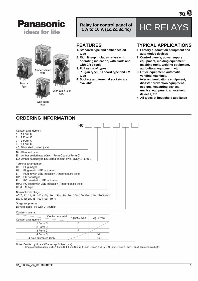
ORDERING INFORMATION
Relay for control panel of 1 A to 10 A (1c/2c/3c/4c) HC RELAYS
Standardtype
Amber sealedtype
With diodetype
With CR circuittype
FEATURES1. Standard type and amber sealed
type2. Rich lineup includes relays with
operating indication, with diode and with CR circuit
3. Full range of typesPlug-in type, PC board type and TM type
4. Sockets and terminal sockets are available.
TYPICAL APPLICATIONS1. Factory automation equipment and
automotive devices2. Control panels, power supply
equipment, molding equipment, machine tools, welding equipment, agricultural equipment, etc.
3. Office equipment, automatic vending machines, telecommunications equipment, disaster prevention equipment, copiers, measuring devices, medical equipment, amusement devices, etc.
4. All types of household appliance
HC
Terminal arrangementH:HL:L:HP:PL:HPL:HTM:
Plug-in typePlug-in with LED indicationPlug-in with LED indication (Amber sealed type)PC board type PC board with LED indicationPC board with LED indication (Amber sealed type)TM type
Nil:E:ED:
Standard typeAmber sealed type (Only 1 Form C and 2 Form C)Amber sealed type bifurcated contact (twin) (Only 4 Form C)
Contact material
Contact arrangementContact material
AgSnO2 type AgNi type
1 Form C2 Form C3 Form C4 Form C
4-pole bifurcated (twin)
FFF
NilNil
Nominal coil voltageACDC
Surge suppressionD: With diode R: With CR curcuit
6, 12, 24, 48, 100 (100/110), 120 (110/120), 200 (200/220), 240 (220/240) V6, 12, 24, 48, 100 (100/110) V
Contact arrangement1:2:3:4:4D:
1 Form C2 Form C3 Form C4 Form CBifurcated contact (twin)
Notes: Certified by UL and CSA (except for keep type)Please consult us about VDE (1 Form C, 2 Form C, and 4 Form C only) and TV-3 (1 Form C and 2 Form C only) approved products.
HC
2 ds_61C04_en_hc: 310812D
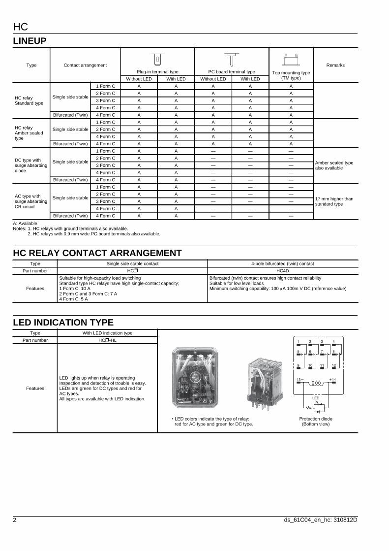
LINEUP
A: AvailableNotes: 1. HC relays with ground terminals also available.
2. HC relays with 0.9 mm wide PC board terminals also available.
HC RELAY CONTACT ARRANGEMENT
LED INDICATION TYPE
Type Contact arrangementPlug-in terminal type PC board terminal type Top mounting type
(TM type)
Remarks
Without LED With LED Without LED With LED
HC relayStandard type
Single side stable
1 Form C A A A A A2 Form C A A A A A3 Form C A A A A A4 Form C A A A A A
Bifurcated (Twin) 4 Form C A A A A A
HC relayAmber sealed type
Single side stable1 Form C A A A A A2 Form C A A A A A4 Form C A A A A A
Bifurcated (Twin) 4 Form C A A A A A
DC type with surge absorbing diode
Single side stable
1 Form C A A — — —
Amber sealed type also available
2 Form C A A — — —3 Form C A A — — —4 Form C A A — — —
Bifurcated (Twin) 4 Form C A A — — —
AC type with surge absorbing CR circuit
Single side stable
1 Form C A A — — —
17 mm higher than standard type
2 Form C A A — — —3 Form C A A — — —4 Form C A A — — —
Bifurcated (Twin) 4 Form C A A — — —
Type Single side stable contact 4-pole bifurcated (twin) contactPart number HC HC4D
Features
Suitable for high-capacity load switchingStandard type HC relays have high single-contact capacity;1 Form C: 10 A2 Form C and 3 Form C: 7 A4 Form C: 5 A
Bifurcated (twin) contact ensures high contact reliability Suitable for low level loadsMinimum switching capability: 100 A 100m V DC (reference value)
Type With LED indication typePart number HC-HL
Features
LED lights up when relay is operatingInspection and detection of trouble is easy.LEDs are green for DC types and red for AC types. All types are available with LED indication.
1 2 3 4
5 6 7 8
9 10 11 12
13– +14
LED
• LED colors indicate the type of relay: red for AC type and green for DC type.
Protection diode(Bottom view)
HC
3ds_61C04_en_hc: 310812D
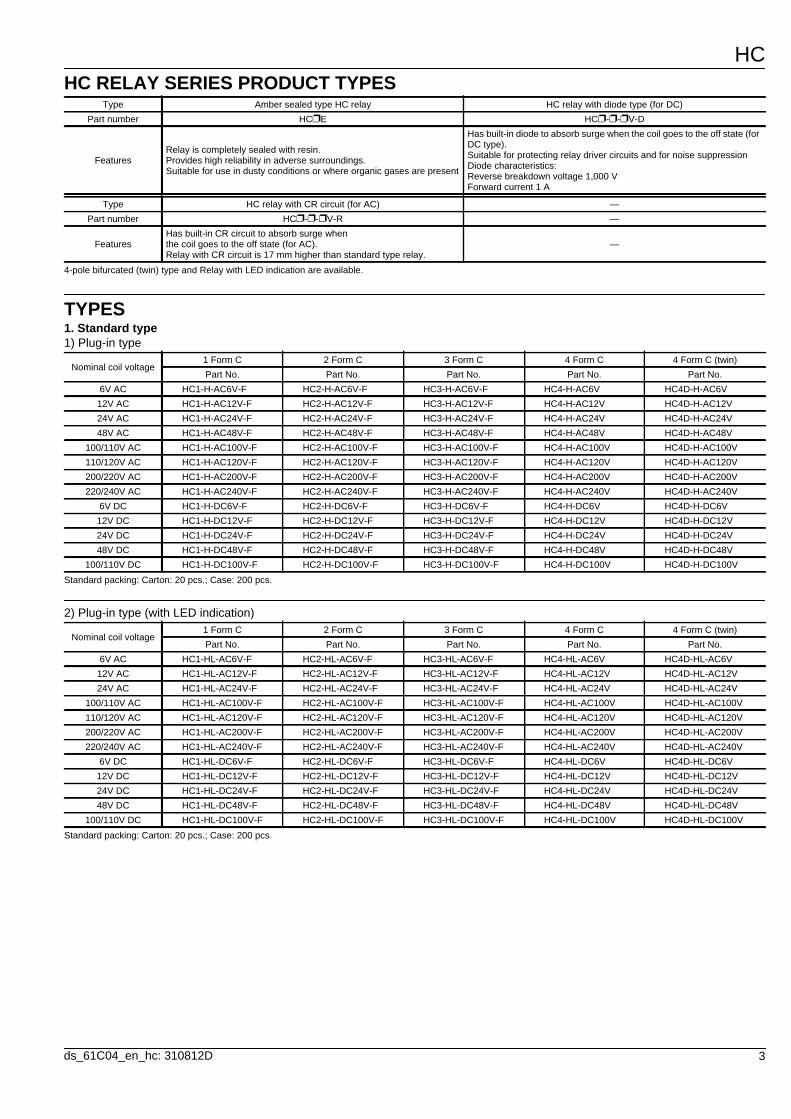
HC RELAY SERIES PRODUCT TYPES
4-pole bifurcated (twin) type and Relay with LED indication are available.
TYPES1. Standard type1) Plug-in type
Standard packing: Carton: 20 pcs.; Case: 200 pcs.
2) Plug-in type (with LED indication)
Standard packing: Carton: 20 pcs.; Case: 200 pcs.
Type Amber sealed type HC relay HC relay with diode type (for DC)Part number HCE HC--V-D
FeaturesRelay is completely sealed with resin.Provides high reliability in adverse surroundings.Suitable for use in dusty conditions or where organic gases are present
Has built-in diode to absorb surge when the coil goes to the off state (for DC type).Suitable for protecting relay driver circuits and for noise suppressionDiode characteristics: Reverse breakdown voltage 1,000 VForward current 1 A
Type HC relay with CR circuit (for AC) —Part number HC--V-R —
FeaturesHas built-in CR circuit to absorb surge when the coil goes to the off state (for AC).Relay with CR circuit is 17 mm higher than standard type relay.
—
Nominal coil voltage1 Form C 2 Form C 3 Form C 4 Form C 4 Form C (twin)Part No. Part No. Part No. Part No. Part No.
6V AC HC1-H-AC6V-F HC2-H-AC6V-F HC3-H-AC6V-F HC4-H-AC6V HC4D-H-AC6V12V AC HC1-H-AC12V-F HC2-H-AC12V-F HC3-H-AC12V-F HC4-H-AC12V HC4D-H-AC12V24V AC HC1-H-AC24V-F HC2-H-AC24V-F HC3-H-AC24V-F HC4-H-AC24V HC4D-H-AC24V48V AC HC1-H-AC48V-F HC2-H-AC48V-F HC3-H-AC48V-F HC4-H-AC48V HC4D-H-AC48V
100/110V AC HC1-H-AC100V-F HC2-H-AC100V-F HC3-H-AC100V-F HC4-H-AC100V HC4D-H-AC100V110/120V AC HC1-H-AC120V-F HC2-H-AC120V-F HC3-H-AC120V-F HC4-H-AC120V HC4D-H-AC120V200/220V AC HC1-H-AC200V-F HC2-H-AC200V-F HC3-H-AC200V-F HC4-H-AC200V HC4D-H-AC200V220/240V AC HC1-H-AC240V-F HC2-H-AC240V-F HC3-H-AC240V-F HC4-H-AC240V HC4D-H-AC240V
6V DC HC1-H-DC6V-F HC2-H-DC6V-F HC3-H-DC6V-F HC4-H-DC6V HC4D-H-DC6V12V DC HC1-H-DC12V-F HC2-H-DC12V-F HC3-H-DC12V-F HC4-H-DC12V HC4D-H-DC12V24V DC HC1-H-DC24V-F HC2-H-DC24V-F HC3-H-DC24V-F HC4-H-DC24V HC4D-H-DC24V48V DC HC1-H-DC48V-F HC2-H-DC48V-F HC3-H-DC48V-F HC4-H-DC48V HC4D-H-DC48V
100/110V DC HC1-H-DC100V-F HC2-H-DC100V-F HC3-H-DC100V-F HC4-H-DC100V HC4D-H-DC100V
Nominal coil voltage1 Form C 2 Form C 3 Form C 4 Form C 4 Form C (twin)Part No. Part No. Part No. Part No. Part No.
6V AC HC1-HL-AC6V-F HC2-HL-AC6V-F HC3-HL-AC6V-F HC4-HL-AC6V HC4D-HL-AC6V12V AC HC1-HL-AC12V-F HC2-HL-AC12V-F HC3-HL-AC12V-F HC4-HL-AC12V HC4D-HL-AC12V24V AC HC1-HL-AC24V-F HC2-HL-AC24V-F HC3-HL-AC24V-F HC4-HL-AC24V HC4D-HL-AC24V
100/110V AC HC1-HL-AC100V-F HC2-HL-AC100V-F HC3-HL-AC100V-F HC4-HL-AC100V HC4D-HL-AC100V110/120V AC HC1-HL-AC120V-F HC2-HL-AC120V-F HC3-HL-AC120V-F HC4-HL-AC120V HC4D-HL-AC120V200/220V AC HC1-HL-AC200V-F HC2-HL-AC200V-F HC3-HL-AC200V-F HC4-HL-AC200V HC4D-HL-AC200V220/240V AC HC1-HL-AC240V-F HC2-HL-AC240V-F HC3-HL-AC240V-F HC4-HL-AC240V HC4D-HL-AC240V
6V DC HC1-HL-DC6V-F HC2-HL-DC6V-F HC3-HL-DC6V-F HC4-HL-DC6V HC4D-HL-DC6V12V DC HC1-HL-DC12V-F HC2-HL-DC12V-F HC3-HL-DC12V-F HC4-HL-DC12V HC4D-HL-DC12V24V DC HC1-HL-DC24V-F HC2-HL-DC24V-F HC3-HL-DC24V-F HC4-HL-DC24V HC4D-HL-DC24V48V DC HC1-HL-DC48V-F HC2-HL-DC48V-F HC3-HL-DC48V-F HC4-HL-DC48V HC4D-HL-DC48V
100/110V DC HC1-HL-DC100V-F HC2-HL-DC100V-F HC3-HL-DC100V-F HC4-HL-DC100V HC4D-HL-DC100V
HC
4 ds_61C04_en_hc: 310812D
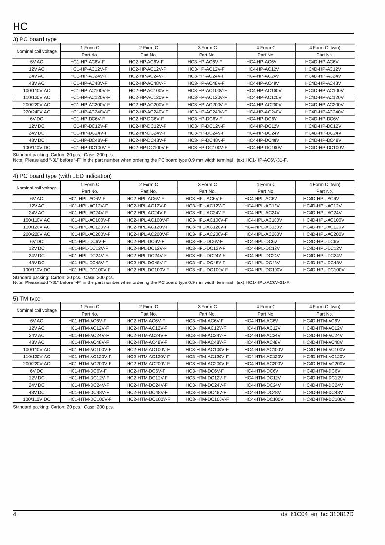
3) PC board type
Standard packing: Carton: 20 pcs.; Case: 200 pcs.Note: Please add “-31” before “-F” in the part number when ordering the PC board type 0.9 mm width terminal (ex) HC1-HP-AC6V-31-F.
4) PC board type (with LED indication)
Standard packing: Carton: 20 pcs.; Case: 200 pcs.Note: Please add “-31” before “-F” in the part number when ordering the PC board type 0.9 mm width terminal (ex) HC1-HPL-AC6V-31-F.
5) TM type
Standard packing: Carton: 20 pcs.; Case: 200 pcs.
Nominal coil voltage1 Form C 2 Form C 3 Form C 4 Form C 4 Form C (twin)Part No. Part No. Part No. Part No. Part No.
6V AC HC1-HP-AC6V-F HC2-HP-AC6V-F HC3-HP-AC6V-F HC4-HP-AC6V HC4D-HP-AC6V12V AC HC1-HP-AC12V-F HC2-HP-AC12V-F HC3-HP-AC12V-F HC4-HP-AC12V HC4D-HP-AC12V24V AC HC1-HP-AC24V-F HC2-HP-AC24V-F HC3-HP-AC24V-F HC4-HP-AC24V HC4D-HP-AC24V48V AC HC1-HP-AC48V-F HC2-HP-AC48V-F HC3-HP-AC48V-F HC4-HP-AC48V HC4D-HP-AC48V
100/110V AC HC1-HP-AC100V-F HC2-HP-AC100V-F HC3-HP-AC100V-F HC4-HP-AC100V HC4D-HP-AC100V110/120V AC HC1-HP-AC120V-F HC2-HP-AC120V-F HC3-HP-AC120V-F HC4-HP-AC120V HC4D-HP-AC120V200/220V AC HC1-HP-AC200V-F HC2-HP-AC200V-F HC3-HP-AC200V-F HC4-HP-AC200V HC4D-HP-AC200V220/240V AC HC1-HP-AC240V-F HC2-HP-AC240V-F HC3-HP-AC240V-F HC4-HP-AC240V HC4D-HP-AC240V
6V DC HC1-HP-DC6V-F HC2-HP-DC6V-F HC3-HP-DC6V-F HC4-HP-DC6V HC4D-HP-DC6V12V DC HC1-HP-DC12V-F HC2-HP-DC12V-F HC3-HP-DC12V-F HC4-HP-DC12V HC4D-HP-DC12V24V DC HC1-HP-DC24V-F HC2-HP-DC24V-F HC3-HP-DC24V-F HC4-HP-DC24V HC4D-HP-DC24V48V DC HC1-HP-DC48V-F HC2-HP-DC48V-F HC3-HP-DC48V-F HC4-HP-DC48V HC4D-HP-DC48V
100/110V DC HC1-HP-DC100V-F HC2-HP-DC100V-F HC3-HP-DC100V-F HC4-HP-DC100V HC4D-HP-DC100V
Nominal coil voltage1 Form C 2 Form C 3 Form C 4 Form C 4 Form C (twin)Part No. Part No. Part No. Part No. Part No.
6V AC HC1-HPL-AC6V-F HC2-HPL-AC6V-F HC3-HPL-AC6V-F HC4-HPL-AC6V HC4D-HPL-AC6V12V AC HC1-HPL-AC12V-F HC2-HPL-AC12V-F HC3-HPL-AC12V-F HC4-HPL-AC12V HC4D-HPL-AC12V24V AC HC1-HPL-AC24V-F HC2-HPL-AC24V-F HC3-HPL-AC24V-F HC4-HPL-AC24V HC4D-HPL-AC24V
100/110V AC HC1-HPL-AC100V-F HC2-HPL-AC100V-F HC3-HPL-AC100V-F HC4-HPL-AC100V HC4D-HPL-AC100V110/120V AC HC1-HPL-AC120V-F HC2-HPL-AC120V-F HC3-HPL-AC120V-F HC4-HPL-AC120V HC4D-HPL-AC120V200/220V AC HC1-HPL-AC200V-F HC2-HPL-AC200V-F HC3-HPL-AC200V-F HC4-HPL-AC200V HC4D-HPL-AC200V
6V DC HC1-HPL-DC6V-F HC2-HPL-DC6V-F HC3-HPL-DC6V-F HC4-HPL-DC6V HC4D-HPL-DC6V12V DC HC1-HPL-DC12V-F HC2-HPL-DC12V-F HC3-HPL-DC12V-F HC4-HPL-DC12V HC4D-HPL-DC12V24V DC HC1-HPL-DC24V-F HC2-HPL-DC24V-F HC3-HPL-DC24V-F HC4-HPL-DC24V HC4D-HPL-DC24V48V DC HC1-HPL-DC48V-F HC2-HPL-DC48V-F HC3-HPL-DC48V-F HC4-HPL-DC48V HC4D-HPL-DC48V
100/110V DC HC1-HPL-DC100V-F HC2-HPL-DC100V-F HC3-HPL-DC100V-F HC4-HPL-DC100V HC4D-HPL-DC100V
Nominal coil voltage1 Form C 2 Form C 3 Form C 4 Form C 4 Form C (twin)Part No. Part No. Part No. Part No. Part No.
6V AC HC1-HTM-AC6V-F HC2-HTM-AC6V-F HC3-HTM-AC6V-F HC4-HTM-AC6V HC4D-HTM-AC6V12V AC HC1-HTM-AC12V-F HC2-HTM-AC12V-F HC3-HTM-AC12V-F HC4-HTM-AC12V HC4D-HTM-AC12V24V AC HC1-HTM-AC24V-F HC2-HTM-AC24V-F HC3-HTM-AC24V-F HC4-HTM-AC24V HC4D-HTM-AC24V48V AC HC1-HTM-AC48V-F HC2-HTM-AC48V-F HC3-HTM-AC48V-F HC4-HTM-AC48V HC4D-HTM-AC48V
100/110V AC HC1-HTM-AC100V-F HC2-HTM-AC100V-F HC3-HTM-AC100V-F HC4-HTM-AC100V HC4D-HTM-AC100V110/120V AC HC1-HTM-AC120V-F HC2-HTM-AC120V-F HC3-HTM-AC120V-F HC4-HTM-AC120V HC4D-HTM-AC120V200/220V AC HC1-HTM-AC200V-F HC2-HTM-AC200V-F HC3-HTM-AC200V-F HC4-HTM-AC200V HC4D-HTM-AC200V
6V DC HC1-HTM-DC6V-F HC2-HTM-DC6V-F HC3-HTM-DC6V-F HC4-HTM-DC6V HC4D-HTM-DC6V12V DC HC1-HTM-DC12V-F HC2-HTM-DC12V-F HC3-HTM-DC12V-F HC4-HTM-DC12V HC4D-HTM-DC12V24V DC HC1-HTM-DC24V-F HC2-HTM-DC24V-F HC3-HTM-DC24V-F HC4-HTM-DC24V HC4D-HTM-DC24V48V DC HC1-HTM-DC48V-F HC2-HTM-DC48V-F HC3-HTM-DC48V-F HC4-HTM-DC48V HC4D-HTM-DC48V
100/110V DC HC1-HTM-DC100V-F HC2-HTM-DC100V-F HC3-HTM-DC100V-F HC4-HTM-DC100V HC4D-HTM-DC100V
HC
5ds_61C04_en_hc: 310812D
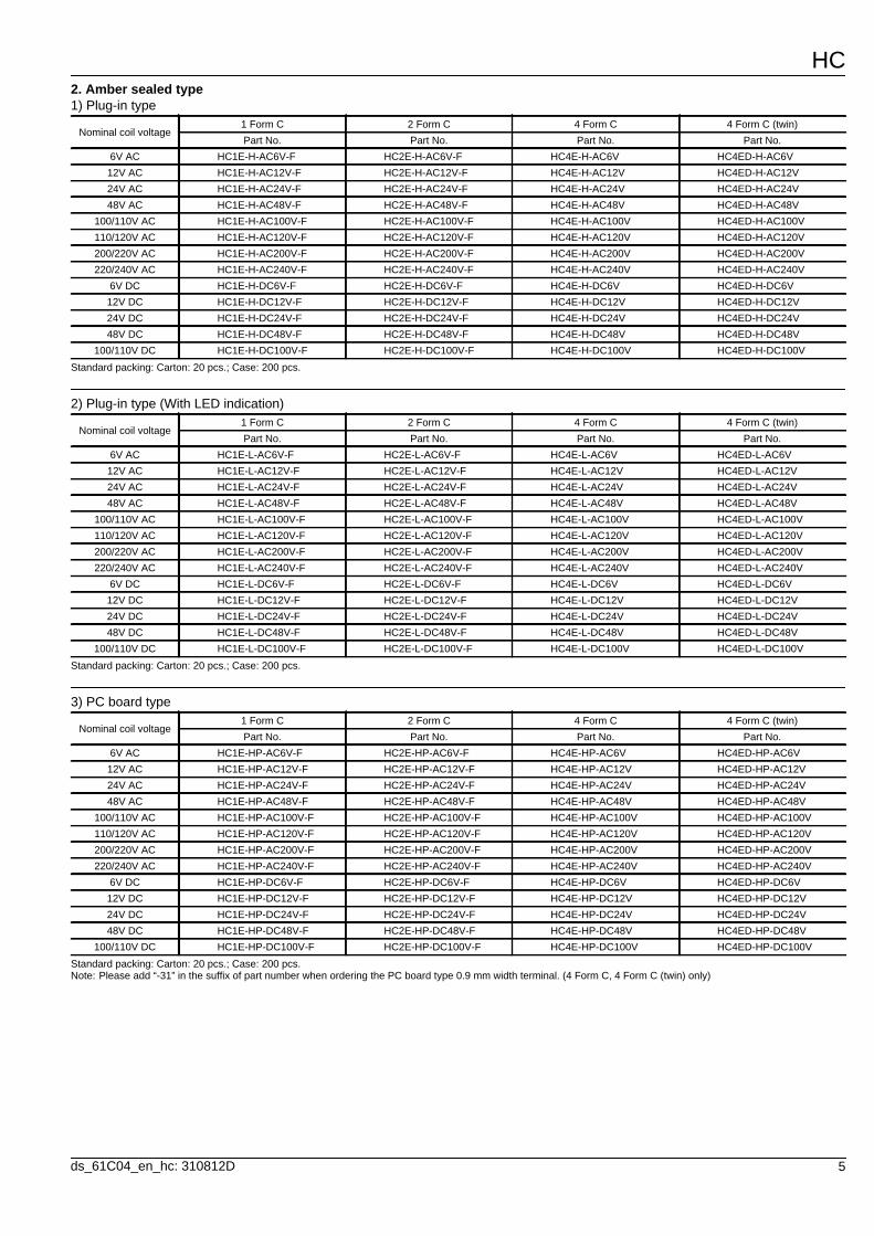
2. Amber sealed type1) Plug-in type
Standard packing: Carton: 20 pcs.; Case: 200 pcs.
2) Plug-in type (With LED indication)
Standard packing: Carton: 20 pcs.; Case: 200 pcs.
3) PC board type
Standard packing: Carton: 20 pcs.; Case: 200 pcs.Note: Please add “-31” in the suffix of part number when ordering the PC board type 0.9 mm width terminal. (4 Form C, 4 Form C (twin) only)
Nominal coil voltage1 Form C 2 Form C 4 Form C 4 Form C (twin)Part No. Part No. Part No. Part No.
6V AC HC1E-H-AC6V-F HC2E-H-AC6V-F HC4E-H-AC6V HC4ED-H-AC6V12V AC HC1E-H-AC12V-F HC2E-H-AC12V-F HC4E-H-AC12V HC4ED-H-AC12V24V AC HC1E-H-AC24V-F HC2E-H-AC24V-F HC4E-H-AC24V HC4ED-H-AC24V48V AC HC1E-H-AC48V-F HC2E-H-AC48V-F HC4E-H-AC48V HC4ED-H-AC48V
100/110V AC HC1E-H-AC100V-F HC2E-H-AC100V-F HC4E-H-AC100V HC4ED-H-AC100V110/120V AC HC1E-H-AC120V-F HC2E-H-AC120V-F HC4E-H-AC120V HC4ED-H-AC120V200/220V AC HC1E-H-AC200V-F HC2E-H-AC200V-F HC4E-H-AC200V HC4ED-H-AC200V220/240V AC HC1E-H-AC240V-F HC2E-H-AC240V-F HC4E-H-AC240V HC4ED-H-AC240V
6V DC HC1E-H-DC6V-F HC2E-H-DC6V-F HC4E-H-DC6V HC4ED-H-DC6V12V DC HC1E-H-DC12V-F HC2E-H-DC12V-F HC4E-H-DC12V HC4ED-H-DC12V24V DC HC1E-H-DC24V-F HC2E-H-DC24V-F HC4E-H-DC24V HC4ED-H-DC24V48V DC HC1E-H-DC48V-F HC2E-H-DC48V-F HC4E-H-DC48V HC4ED-H-DC48V
100/110V DC HC1E-H-DC100V-F HC2E-H-DC100V-F HC4E-H-DC100V HC4ED-H-DC100V
Nominal coil voltage1 Form C 2 Form C 4 Form C 4 Form C (twin)Part No. Part No. Part No. Part No.
6V AC HC1E-L-AC6V-F HC2E-L-AC6V-F HC4E-L-AC6V HC4ED-L-AC6V12V AC HC1E-L-AC12V-F HC2E-L-AC12V-F HC4E-L-AC12V HC4ED-L-AC12V24V AC HC1E-L-AC24V-F HC2E-L-AC24V-F HC4E-L-AC24V HC4ED-L-AC24V48V AC HC1E-L-AC48V-F HC2E-L-AC48V-F HC4E-L-AC48V HC4ED-L-AC48V
100/110V AC HC1E-L-AC100V-F HC2E-L-AC100V-F HC4E-L-AC100V HC4ED-L-AC100V110/120V AC HC1E-L-AC120V-F HC2E-L-AC120V-F HC4E-L-AC120V HC4ED-L-AC120V200/220V AC HC1E-L-AC200V-F HC2E-L-AC200V-F HC4E-L-AC200V HC4ED-L-AC200V220/240V AC HC1E-L-AC240V-F HC2E-L-AC240V-F HC4E-L-AC240V HC4ED-L-AC240V
6V DC HC1E-L-DC6V-F HC2E-L-DC6V-F HC4E-L-DC6V HC4ED-L-DC6V12V DC HC1E-L-DC12V-F HC2E-L-DC12V-F HC4E-L-DC12V HC4ED-L-DC12V24V DC HC1E-L-DC24V-F HC2E-L-DC24V-F HC4E-L-DC24V HC4ED-L-DC24V48V DC HC1E-L-DC48V-F HC2E-L-DC48V-F HC4E-L-DC48V HC4ED-L-DC48V
100/110V DC HC1E-L-DC100V-F HC2E-L-DC100V-F HC4E-L-DC100V HC4ED-L-DC100V
Nominal coil voltage1 Form C 2 Form C 4 Form C 4 Form C (twin)Part No. Part No. Part No. Part No.
6V AC HC1E-HP-AC6V-F HC2E-HP-AC6V-F HC4E-HP-AC6V HC4ED-HP-AC6V12V AC HC1E-HP-AC12V-F HC2E-HP-AC12V-F HC4E-HP-AC12V HC4ED-HP-AC12V24V AC HC1E-HP-AC24V-F HC2E-HP-AC24V-F HC4E-HP-AC24V HC4ED-HP-AC24V48V AC HC1E-HP-AC48V-F HC2E-HP-AC48V-F HC4E-HP-AC48V HC4ED-HP-AC48V
100/110V AC HC1E-HP-AC100V-F HC2E-HP-AC100V-F HC4E-HP-AC100V HC4ED-HP-AC100V110/120V AC HC1E-HP-AC120V-F HC2E-HP-AC120V-F HC4E-HP-AC120V HC4ED-HP-AC120V200/220V AC HC1E-HP-AC200V-F HC2E-HP-AC200V-F HC4E-HP-AC200V HC4ED-HP-AC200V220/240V AC HC1E-HP-AC240V-F HC2E-HP-AC240V-F HC4E-HP-AC240V HC4ED-HP-AC240V
6V DC HC1E-HP-DC6V-F HC2E-HP-DC6V-F HC4E-HP-DC6V HC4ED-HP-DC6V12V DC HC1E-HP-DC12V-F HC2E-HP-DC12V-F HC4E-HP-DC12V HC4ED-HP-DC12V24V DC HC1E-HP-DC24V-F HC2E-HP-DC24V-F HC4E-HP-DC24V HC4ED-HP-DC24V48V DC HC1E-HP-DC48V-F HC2E-HP-DC48V-F HC4E-HP-DC48V HC4ED-HP-DC48V
100/110V DC HC1E-HP-DC100V-F HC2E-HP-DC100V-F HC4E-HP-DC100V HC4ED-HP-DC100V
HC
6 ds_61C04_en_hc: 310812D
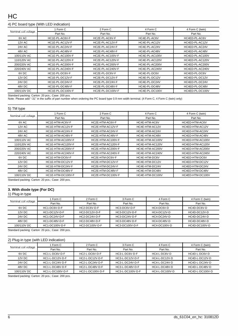
4) PC board type (With LED indication)
Standard packing: Carton: 20 pcs.; Case: 200 pcs.Note: Please add “-31” in the suffix of part number when ordering the PC board type 0.9 mm width terminal. (4 Form C, 4 Form C (twin) only)
5) TM type
Standard packing: Carton: 20 pcs.; Case: 200 pcs.
3. With diode type (For DC)1) Plug-in type
Standard packing: Carton: 20 pcs.; Case: 200 pcs.
2) Plug-in type (with LED indication)
Standard packing: Carton: 20 pcs.; Case: 200 pcs.
Nominal coil voltage1 Form C 2 Form C 4 Form C 4 Form C (twin)Part No. Part No. Part No. Part No.
6V AC HC1E-PL-AC6V-F HC2E-PL-AC6V-F HC4E-PL-AC6V HC4ED-PL-AC6V12V AC HC1E-PL-AC12V-F HC2E-PL-AC12V-F HC4E-PL-AC12V HC4ED-PL-AC12V24V AC HC1E-PL-AC24V-F HC2E-PL-AC24V-F HC4E-PL-AC24V HC4ED-PL-AC24V48V AC HC1E-PL-AC48V-F HC2E-PL-AC48V-F HC4E-PL-AC48V HC4ED-PL-AC48V
100/110V AC HC1E-PL-AC100V-F HC2E-PL-AC100V-F HC4E-PL-AC100V HC4ED-PL-AC100V110/120V AC HC1E-PL-AC120V-F HC2E-PL-AC120V-F HC4E-PL-AC120V HC4ED-PL-AC120V200/220V AC HC1E-PL-AC200V-F HC2E-PL-AC200V-F HC4E-PL-AC200V HC4ED-PL-AC200V220/240V AC HC1E-PL-AC240V-F HC2E-PL-AC240V-F HC4E-PL-AC240V HC4ED-PL-AC240V
6V DC HC1E-PL-DC6V-F HC2E-PL-DC6V-F HC4E-PL-DC6V HC4ED-PL-DC6V12V DC HC1E-PL-DC12V-F HC2E-PL-DC12V-F HC4E-PL-DC12V HC4ED-PL-DC12V24V DC HC1E-PL-DC24V-F HC2E-PL-DC24V-F HC4E-PL-DC24V HC4ED-PL-DC24V48V DC HC1E-PL-DC48V-F HC2E-PL-DC48V-F HC4E-PL-DC48V HC4ED-PL-DC48V
100/110V DC HC1E-PL-DC100V-F HC2E-PL-DC100V-F HC4E-PL-DC100V HC4ED-PL-DC100V
Nominal coil voltage1 Form C 2 Form C 4 Form C 4 Form C (twin)Part No. Part No. Part No. Part No.
6V AC HC1E-HTM-AC6V-F HC2E-HTM-AC6V-F HC4E-HTM-AC6V HC4ED-HTM-AC6V12V AC HC1E-HTM-AC12V-F HC2E-HTM-AC12V-F HC4E-HTM-AC12V HC4ED-HTM-AC12V24V AC HC1E-HTM-AC24V-F HC2E-HTM-AC24V-F HC4E-HTM-AC24V HC4ED-HTM-AC24V48V AC HC1E-HTM-AC48V-F HC2E-HTM-AC48V-F HC4E-HTM-AC48V HC4ED-HTM-AC48V
100/110V AC HC1E-HTM-AC100V-F HC2E-HTM-AC100V-F HC4E-HTM-AC100V HC4ED-HTM-AC100V110/120V AC HC1E-HTM-AC120V-F HC2E-HTM-AC120V-F HC4E-HTM-AC120V HC4ED-HTM-AC120V200/220V AC HC1E-HTM-AC200V-F HC2E-HTM-AC200V-F HC4E-HTM-AC200V HC4ED-HTM-AC200V220/240V AC HC1E-HTM-AC240V-F HC2E-HTM-AC240V-F HC4E-HTM-AC240V HC4ED-HTM-AC240V
6V DC HC1E-HTM-DC6V-F HC2E-HTM-DC6V-F HC4E-HTM-DC6V HC4ED-HTM-DC6V12V DC HC1E-HTM-DC12V-F HC2E-HTM-DC12V-F HC4E-HTM-DC12V HC4ED-HTM-DC12V24V DC HC1E-HTM-DC24V-F HC2E-HTM-DC24V-F HC4E-HTM-DC24V HC4ED-HTM-DC24V48V DC HC1E-HTM-DC48V-F HC2E-HTM-DC48V-F HC4E-HTM-DC48V HC4ED-HTM-DC48V
100/110V DC HC1E-HTM-DC100V-F HC2E-HTM-DC100V-F HC4E-HTM-DC100V HC4ED-HTM-DC100V
Nominal coil voltage1 Form C 2 Form C 3 Form C 4 Form C 4 Form C (twin)Part No. Part No. Part No. Part No. Part No.
6V DC HC1-DC6V-D-F HC2-DC6V-D-F HC3-DC6V-D-F HC4-DC6V-D HC4D-DC6V-D12V DC HC1-DC12V-D-F HC2-DC12V-D-F HC3-DC12V-D-F HC4-DC12V-D HC4D-DC12V-D24V DC HC1-DC24V-D-F HC2-DC24V-D-F HC3-DC24V-D-F HC4-DC24V-D HC4D-DC24V-D48V DC HC1-DC48V-D-F HC2-DC48V-D-F HC3-DC48V-D-F HC4-DC48V-D HC4D-DC48V-D
100/110V DC HC1-DC100V-D-F HC2-DC100V-D-F HC3-DC100V-D-F HC4-DC100V-D HC4D-DC100V-D
Nominal coil voltage1 Form C 2 Form C 3 Form C 4 Form C 4 Form C (twin)Part No. Part No. Part No. Part No. Part No.
6V DC HC1-L-DC6V-D-F HC2-L-DC6V-D-F HC3-L-DC6V-D-F HC4-L-DC6V-D HC4D-L-DC6V-D12V DC HC1-L-DC12V-D-F HC2-L-DC12V-D-F HC3-L-DC12V-D-F HC4-L-DC12V-D HC4D-L-DC12V-D24V DC HC1-L-DC24V-D-F HC2-L-DC24V-D-F HC3-L-DC24V-D-F HC4-L-DC24V-D HC4D-L-DC24V-D48V DC HC1-L-DC48V-D-F HC2-L-DC48V-D-F HC3-L-DC48V-D-F HC4-L-DC48V-D HC4D-L-DC48V-D
100/110V DC HC1-L-DC100V-D-F HC2-L-DC100V-D-F HC3-L-DC100V-D-F HC4-L-DC100V-D HC4D-L-DC100V-D
HC
7ds_61C04_en_hc: 310812D
4. With CR circuit type1) Plug-in type
Standard packing: Carton: 20 pcs.; Case: 200 pcs.
2) Plug-in type (with LED indication)
Standard packing: Carton: 20 pcs.; Case: 200 pcs.
* For sockets and terminal sockets, see page 20.
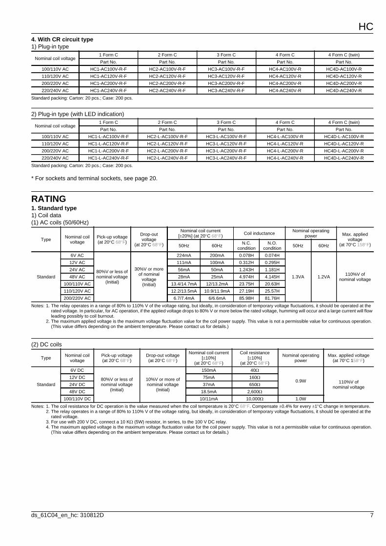
RATING1. Standard type1) Coil data(1) AC coils (50/60Hz)
Notes: 1. The relay operates in a range of 80% to 110% V of the voltage rating, but ideally, in consideration of temporary voltage fluctuations, it should be operated at the rated voltage. In particular, for AC operation, if the applied voltage drops to 80% V or more below the rated voltage, humming will occur and a large current will flow leading possibly to coil burnout.
2. The maximum applied voltage is the maximum voltage fluctuation value for the coil power supply. This value is not a permissible value for continuous operation. (This value differs depending on the ambient temperature. Please contact us for details.)
(2) DC coils
Notes: 1. The coil resistance for DC operation is the value measured when the coil temperature is 20C 68F. Compensate 0.4% for every 1C change in temperature.2. The relay operates in a range of 80% to 110% V of the voltage rating, but ideally, in consideration of temporary voltage fluctuations, it should be operated at the
rated voltage.3. For use with 200 V DC, connect a 10 K (5W) resistor, in series, to the 100 V DC relay.4. The maximum applied voltage is the maximum voltage fluctuation value for the coil power supply. This value is not a permissible value for continuous operation.
(This value differs depending on the ambient temperature. Please contact us for details.)
Nominal coil voltage1 Form C 2 Form C 3 Form C 4 Form C 4 Form C (twin)Part No. Part No. Part No. Part No. Part No.
100/110V AC HC1-AC100V-R-F HC2-AC100V-R-F HC3-AC100V-R-F HC4-AC100V-R HC4D-AC100V-R110/120V AC HC1-AC120V-R-F HC2-AC120V-R-F HC3-AC120V-R-F HC4-AC120V-R HC4D-AC120V-R200/220V AC HC1-AC200V-R-F HC2-AC200V-R-F HC3-AC200V-R-F HC4-AC200V-R HC4D-AC200V-R220/240V AC HC1-AC240V-R-F HC2-AC240V-R-F HC3-AC240V-R-F HC4-AC240V-R HC4D-AC240V-R
Nominal coil voltage1 Form C 2 Form C 3 Form C 4 Form C 4 Form C (twin)Part No. Part No. Part No. Part No. Part No.
100/110V AC HC1-L-AC100V-R-F HC2-L-AC100V-R-F HC3-L-AC100V-R-F HC4-L-AC100V-R HC4D-L-AC100V-R110/120V AC HC1-L-AC120V-R-F HC2-L-AC120V-R-F HC3-L-AC120V-R-F HC4-L-AC120V-R HC4D-L-AC120V-R200/220V AC HC1-L-AC200V-R-F HC2-L-AC200V-R-F HC3-L-AC200V-R-F HC4-L-AC200V-R HC4D-L-AC200V-R220/240V AC HC1-L-AC240V-R-F HC2-L-AC240V-R-F HC3-L-AC240V-R-F HC4-L-AC240V-R HC4D-L-AC240V-R
Type Nominal coil voltage
Pick-up voltage (at 20C 68F)
Drop-out voltage
(at 20C 68F)
Nominal coil current [20%] (at 20C 68F) Coil inductance Nominal operating
power Max. applied voltage
(at 70C 158F)50Hz 60Hz N.C. condition
N.O. condition 50Hz 60Hz
Standard
6V AC
80%V or less of nominal voltage
(Initial)
30%V or more of nominal
voltage (Initial)
224mA 200mA 0.078H 0.074H
1.3VA 1.2VA 110%V of nominal voltage
12V AC 111mA 100mA 0.312H 0.295H24V AC 56mA 50mA 1.243H 1.181H48V AC 28mA 25mA 4.974H 4.145H
100/110V AC 13.4/14.7mA 12/13.2mA 23.75H 20.63H110/120V AC 12.2/13.5mA 10.9/11.9mA 27.19H 25.57H200/220V AC 6.7/7.4mA 6/6.6mA 85.98H 81.76H
Type Nominal coil voltage
Pick-up voltage (at 20C 68F)
Drop-out voltage (at 20C 68F)
Nominal coil current [10%]
(at 20C 68F)
Coil resistance [10%]
(at 20C 68F)
Nominal operating power
Max. applied voltage (at 70C 158F)
Standard
6V DC
80%V or less of nominal voltage
(Initial)
10%V or more of nominal voltage
(Initial)
150mA 40
0.9W 110%V of nominal voltage
12V DC 75mA 16024V DC 37mA 65048V DC 18.5mA 2,600
100/110V DC 10/11mA 10,000 1.0W
HC
8 ds_61C04_en_hc: 310812D
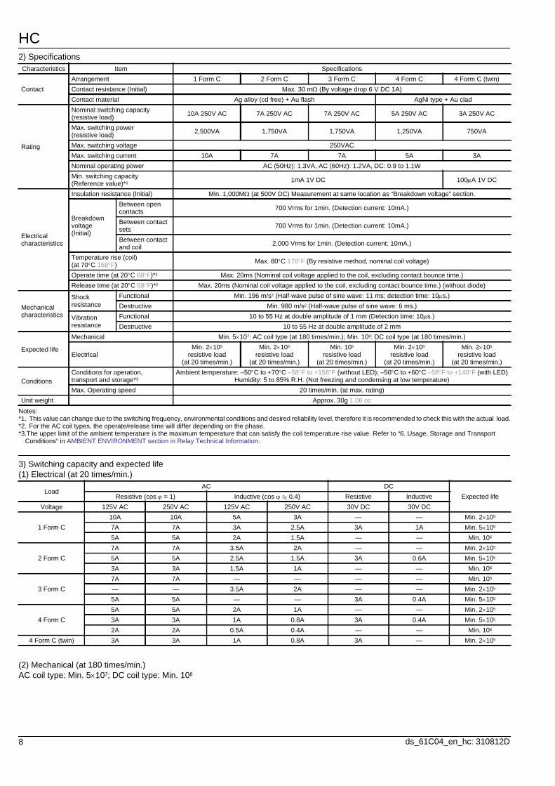
2) Specifications
Notes:*1. This value can change due to the switching frequency, environmental conditions and desired reliability level, therefore it is recommended to check this with the actual load.*2. For the AC coil types, the operate/release time will differ depending on the phase.*3.The upper limit of the ambient temperature is the maximum temperature that can satisfy the coil temperature rise value. Refer to “6. Usage, Storage and Transport
Conditions“ in AMBIENT ENVIRONMENT section in Relay Technical Information.
3) Switching capacity and expected life(1) Electrical (at 20 times/min.)
(2) Mechanical (at 180 times/min.)AC coil type: Min. 5107; DC coil type: Min. 108
Characteristics Item Specifications
ContactArrangement 1 Form C 2 Form C 3 Form C 4 Form C 4 Form C (twin)Contact resistance (Initial) Max. 30 m (By voltage drop 6 V DC 1A)Contact material Ag alloy (cd free) + Au flash AgNi type + Au clad
Rating
Nominal switching capacity (resistive load) 10A 250V AC 7A 250V AC 7A 250V AC 5A 250V AC 3A 250V AC
Max. switching power (resistive load) 2,500VA 1,750VA 1,750VA 1,250VA 750VA
Max. switching voltage 250VACMax. switching current 10A 7A 7A 5A 3ANominal operating power AC (50Hz): 1.3VA, AC (60Hz): 1.2VA, DC: 0.9 to 1.1WMin. switching capacity (Reference value)*1 1mA 1V DC 100A 1V DC
Electrical characteristics
Insulation resistance (Initial) Min. 1,000M (at 500V DC) Measurement at same location as “Breakdown voltage” section.
Breakdown voltage (Initial)
Between open contacts 700 Vrms for 1min. (Detection current: 10mA.)
Between contact sets 700 Vrms for 1min. (Detection current: 10mA.)
Between contact and coil 2,000 Vrms for 1min. (Detection current: 10mA.)
Temperature rise (coil) (at 70C 158F) Max. 80C 176F (By resistive method, nominal coil voltage)
Operate time (at 20C 68F)*2 Max. 20ms (Nominal coil voltage applied to the coil, excluding contact bounce time.)Release time (at 20C 68F)*2 Max. 20ms (Nominal coil voltage applied to the coil, excluding contact bounce time.) (without diode)
Mechanical characteristics
Shock resistance
Functional Min. 196 m/s2 (Half-wave pulse of sine wave: 11 ms; detection time: 10s.)Destructive Min. 980 m/s2 (Half-wave pulse of sine wave: 6 ms.)
Vibration resistance
Functional 10 to 55 Hz at double amplitude of 1 mm (Detection time: 10s.)Destructive 10 to 55 Hz at double amplitude of 2 mm
Expected life
Mechanical Min. 5107: AC coil type (at 180 times/min.); Min. 108: DC coil type (at 180 times/min.)
ElectricalMin. 2105
resistive load(at 20 times/min.)
Min. 2105 resistive load
(at 20 times/min.)
Min. 105 resistive load
(at 20 times/min.)
Min. 2105 resistive load
(at 20 times/min.)
Min. 2105 resistive load
(at 20 times/min.)
ConditionsConditions for operation, transport and storage*3
Ambient temperature: –50C to +70C –58F to +158F (without LED); –50C to +60C –58F to +140F (with LED)Humidity: 5 to 85% R.H. (Not freezing and condensing at low temperature)
Max. Operating speed 20 times/min. (at max. rating)Unit weight Approx. 30g 1.06 oz
LoadAC DC
Expected lifeResistive (cos = 1) Inductive (cos 0.4) Resistive InductiveVoltage 125V AC 250V AC 125V AC 250V AC 30V DC 30V DC
1 Form C10A 10A 5A 3A — — Min. 2105
7A 7A 3A 2.5A 3A 1A Min. 5105
5A 5A 2A 1.5A — — Min. 106
2 Form C7A 7A 3.5A 2A — — Min. 2105
5A 5A 2.5A 1.5A 3A 0.6A Min. 5105
3A 3A 1.5A 1A — — Min. 106
3 Form C7A 7A — — — — Min. 105
— — 3.5A 2A — — Min. 2105
5A 5A — — 3A 0.4A Min. 5105
4 Form C5A 5A 2A 1A — — Min. 2105
3A 3A 1A 0.8A 3A 0.4A Min. 5105
2A 2A 0.5A 0.4A — — Min. 106
4 Form C (twin) 3A 3A 1A 0.8A 3A — Min. 2105
HC
9ds_61C04_en_hc: 310812D
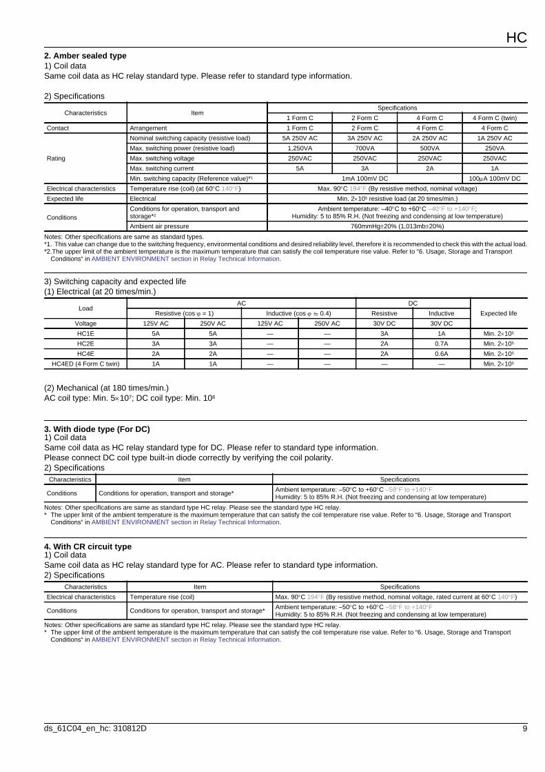
2. Amber sealed type1) Coil dataSame coil data as HC relay standard type. Please refer to standard type information.
2) Specifications
Notes: Other specifications are same as standard types.*1. This value can change due to the switching frequency, environmental conditions and desired reliability level, therefore it is recommended to check this with the actual load.*2.The upper limit of the ambient temperature is the maximum temperature that can satisfy the coil temperature rise value. Refer to “6. Usage, Storage and Transport
Conditions“ in AMBIENT ENVIRONMENT section in Relay Technical Information.
3) Switching capacity and expected life(1) Electrical (at 20 times/min.)
(2) Mechanical (at 180 times/min.)AC coil type: Min. 5107; DC coil type: Min. 108
3. With diode type (For DC)1) Coil dataSame coil data as HC relay standard type for DC. Please refer to standard type information.Please connect DC coil type built-in diode correctly by verifying the coil polarity.2) Specifications
Notes: Other specifications are same as standard type HC relay. Please see the standard type HC relay.* The upper limit of the ambient temperature is the maximum temperature that can satisfy the coil temperature rise value. Refer to “6. Usage, Storage and Transport
Conditions“ in AMBIENT ENVIRONMENT section in Relay Technical Information.
4. With CR circuit type1) Coil dataSame coil data as HC relay standard type for AC. Please refer to standard type information.2) Specifications
Notes: Other specifications are same as standard type HC relay. Please see the standard type HC relay.* The upper limit of the ambient temperature is the maximum temperature that can satisfy the coil temperature rise value. Refer to “6. Usage, Storage and Transport
Conditions“ in AMBIENT ENVIRONMENT section in Relay Technical Information.
Characteristics ItemSpecifications
1 Form C 2 Form C 4 Form C 4 Form C (twin)Contact Arrangement 1 Form C 2 Form C 4 Form C 4 Form C
Rating
Nominal switching capacity (resistive load) 5A 250V AC 3A 250V AC 2A 250V AC 1A 250V ACMax. switching power (resistive load) 1,250VA 700VA 500VA 250VAMax. switching voltage 250VAC 250VAC 250VAC 250VACMax. switching current 5A 3A 2A 1AMin. switching capacity (Reference value)*1 1mA 100mV DC 100A 100mV DC
Electrical characteristics Temperature rise (coil) (at 60C 140F) Max. 90C 194F (By resistive method, nominal voltage)Expected life Electrical Min. 2105 resistive load (at 20 times/min.)
ConditionsConditions for operation, transport and storage*2
Ambient temperature: –40C to +60C –40F to +140F; Humidity: 5 to 85% R.H. (Not freezing and condensing at low temperature)
Ambient air pressure 760mmHg20% (1,013mb20%)
LoadAC DC
Expected lifeResistive (cos = 1) Inductive (cos 0.4) Resistive InductiveVoltage 125V AC 250V AC 125V AC 250V AC 30V DC 30V DCHC1E 5A 5A — — 3A 1A Min. 2105
HC2E 3A 3A — — 2A 0.7A Min. 2105
HC4E 2A 2A — — 2A 0.6A Min. 2105
HC4ED (4 Form C twin) 1A 1A — — — — Min. 2105
Characteristics Item Specifications
Conditions Conditions for operation, transport and storage* Ambient temperature: –50C to +60C –58F to +140F Humidity: 5 to 85% R.H. (Not freezing and condensing at low temperature)
Characteristics Item SpecificationsElectrical characteristics Temperature rise (coil) Max. 90C 194F (By resistive method, nominal voltage, rated current at 60C 140F)
Conditions Conditions for operation, transport and storage* Ambient temperature: –50C to +60C –58F to +140F Humidity: 5 to 85% R.H. (Not freezing and condensing at low temperature)
HC
10 ds_61C04_en_hc: 310812D
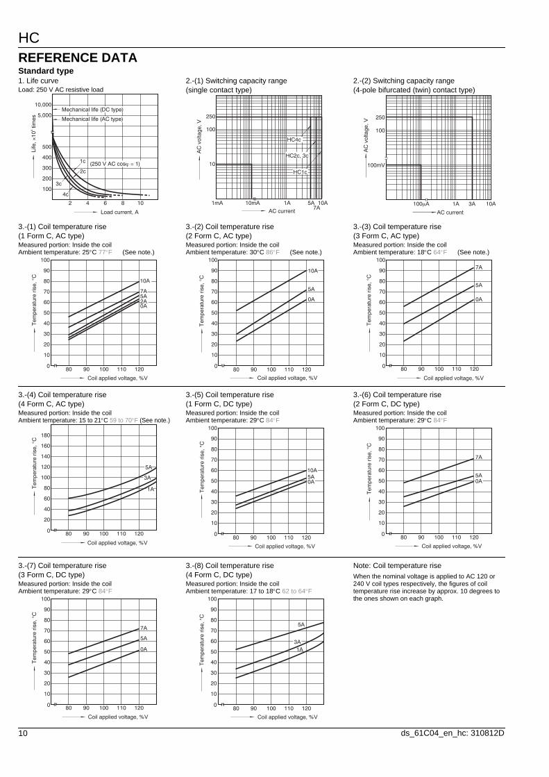
REFERENCE DATAStandard type1. Life curveLoad: 250 V AC resistive load
2.-(1) Switching capacity range (single contact type)
2.-(2) Switching capacity range (4-pole bifurcated (twin) contact type)
2 4 6 8 10
100
200
300
400
500
5,000
10,000
1c
2c
3c
4c
Load current, A
Life
, ×10
4 tim
es
Mechanical life (DC type)
Mechanical life (AC type)
(250 V AC cosϕ = 1)
10mA
100
10
250
1A1mA7A
5A 10A
HC1c
HC4c
HC2c, 3c
AC current
AC
vol
tage
, V100μA
100mV
100
250
1A 3A 10A
AC current
AC
vol
tage
, V
3.-(1) Coil temperature rise (1 Form C, AC type)Measured portion: Inside the coilAmbient temperature: 25C 77F
3.-(2) Coil temperature rise (2 Form C, AC type)Measured portion: Inside the coilAmbient temperature: 30C 86F
3.-(3) Coil temperature rise (3 Form C, AC type)Measured portion: Inside the coilAmbient temperature: 18C 64F (See note.) (See note.) (See note.)
80 90 100 110 1200
10
20
30
40
50
60
70
80
90
100
10A
7A
0A2A5A
Coil applied voltage, %V
Tem
pera
ture
ris
e, °
C
80 90 100 110 1200
10
20
30
40
50
60
70
80
90
100
10A
5A
0A
Coil applied voltage, %V
Tem
pera
ture
ris
e, °
C
80 90 100 110 1200
10
20
30
40
50
60
70
80
90
100
5A
7A
0A
Coil applied voltage, %V
Tem
pera
ture
ris
e, °
C
3.-(4) Coil temperature rise (4 Form C, AC type)Measured portion: Inside the coilAmbient temperature: 15 to 21C 59 to 70F (See note.)
3.-(5) Coil temperature rise (1 Form C, DC type)Measured portion: Inside the coilAmbient temperature: 29C 84F
3.-(6) Coil temperature rise (2 Form C, DC type)Measured portion: Inside the coilAmbient temperature: 29C 84F
80 90 100 110 1200
20
40
60
80
100
120
140
160
180
5A
3A
1A
Coil applied voltage, %V
Tem
pera
ture
ris
e, °
C
80 90 100 110 1200
10
20
30
40
50
60
70
80
90
100
10A5A0A
Coil applied voltage, %V
Tem
pera
ture
ris
e, °
C
80 90 100 110 1200
10
20
30
40
50
60
70
80
90
100
7A
5A0A
Coil applied voltage, %V
Tem
pera
ture
ris
e, °
C
3.-(7) Coil temperature rise (3 Form C, DC type)Measured portion: Inside the coilAmbient temperature: 29C 84F
3.-(8) Coil temperature rise (4 Form C, DC type)Measured portion: Inside the coilAmbient temperature: 17 to 18C 62 to 64F
Note: Coil temperature riseWhen the nominal voltage is applied to AC 120 or 240 V coil types respectively, the figures of coil temperature rise increase by approx. 10 degrees to the ones shown on each graph.
80 90 100 110 1200
10
20
30
40
50
60
70
80
90
100
7A
5A
0A
Coil applied voltage, %V
Tem
pera
ture
ris
e, °
C
80 90 100 110 1200
10
20
30
40
50
60
70
80
90
100
5A
3A1A
Coil applied voltage, %V
Tem
pera
ture
ris
e, °
C
HC
11ds_61C04_en_hc: 310812D
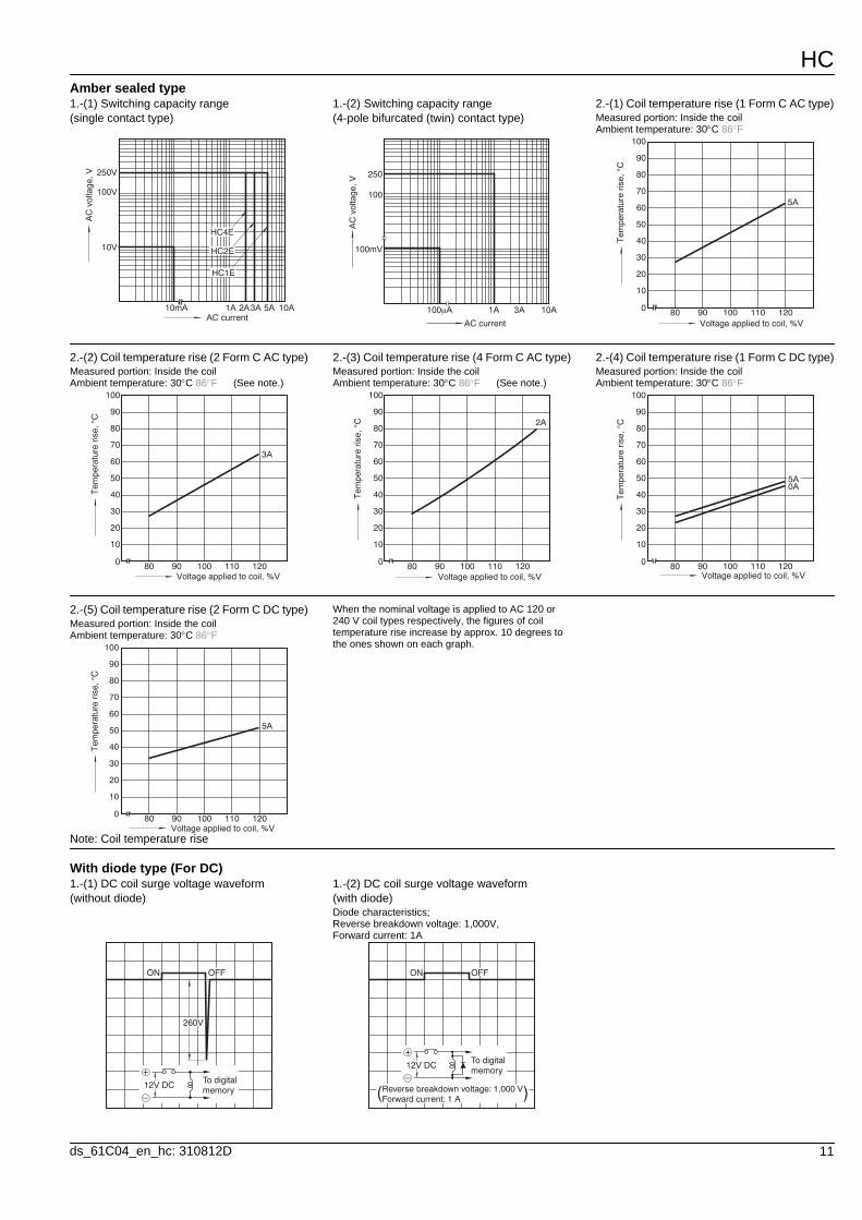
With diode type (For DC)
Amber sealed type1.-(1) Switching capacity range (single contact type)
1.-(2) Switching capacity range (4-pole bifurcated (twin) contact type)
2.-(1) Coil temperature rise (1 Form C AC type)Measured portion: Inside the coilAmbient temperature: 30C 86F
10mA
250V
100V
10V
1A 3A2A 5A 10A
HC1E
HC4E
HC2E
AC current
AC
vol
tage
, V
100μA
100mV
100
250
1A 3A 10A
AC current
AC
vol
tage
, V
80 90 100 110 1200
10
20
30
40
50
60
70
80
90
100
5A
Voltage applied to coil, %V
Tem
pera
ture
ris
e, °
C
2.-(2) Coil temperature rise (2 Form C AC type)Measured portion: Inside the coilAmbient temperature: 30C 86F
2.-(3) Coil temperature rise (4 Form C AC type)Measured portion: Inside the coilAmbient temperature: 30C 86F
2.-(4) Coil temperature rise (1 Form C DC type)Measured portion: Inside the coilAmbient temperature: 30C 86F (See note.) (See note.)
80 90 100 110 1200
10
20
30
40
50
60
70
80
90
100
3A
Voltage applied to coil, %V
Tem
pera
ture
ris
e, °
C
80 90 100 110 1200
10
20
30
40
50
60
70
80
90
100
2A
Voltage applied to coil, %V
Tem
pera
ture
ris
e, °
C
80 90 100 110 1200
10
20
30
40
50
60
70
80
90
100
5A0A
Voltage applied to coil, %V
Tem
pera
ture
ris
e, °
C2.-(5) Coil temperature rise (2 Form C DC type)Measured portion: Inside the coilAmbient temperature: 30C 86F
Note: Coil temperature rise
When the nominal voltage is applied to AC 120 or 240 V coil types respectively, the figures of coil temperature rise increase by approx. 10 degrees to the ones shown on each graph.
80 90 100 110 1200
10
20
30
40
50
60
70
80
90
100
5A
Voltage applied to coil, %V
Tem
pera
ture
ris
e, °
C
1.-(1) DC coil surge voltage waveform (without diode)
1.-(2) DC coil surge voltage waveform (with diode)Diode characteristics; Reverse breakdown voltage: 1,000V, Forward current: 1A
OFFON
260V
12V DC
+
–
To digitalmemory
OFFON
12V DC
+
–
To digitalmemory
( (Reverse breakdown voltage: 1,000 VForward current: 1 A
HC
12 ds_61C04_en_hc: 310812D
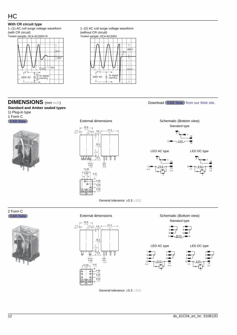
With CR circuit type
DIMENSIONS (mm inch)Standard and Amber sealed types1) Plug-in type
1.-(1) AC coil surge voltage waveform (with CR circuit)Tested sample: HC4-AC200V-R
1.-(2) AC coil surge voltage waveform (without CR circuit)Tested sample: HC4-AC200V
282V
55V
1.5ms3.2ms
200V ACTo digitalmemory
282V
630V
1.8ms
200V ACTo digitalmemory
Download from our Web site.CAD DataCAD Data
1 Form CCAD Data External dimensions
20.8.819
1.7.067
1.7.067
35.21.386
6.4.252
2.54 0.5.100 .020
.52613.35
.1754.45
.1744.41
.1604.06
6.35
6.35.250
.250
27.21.071
.0391
.0240.6
2
7
12
13 14
General tolerance: 0.3 .012
Schematic (Bottom view)Standard type
27
12
1413
LED AC type LED DC type
712
14
2
13(∼)
(∼)
27
12
1413
(−)(+)
2 Form CCAD Data External dimensions
20.8.819
1.7 1.7.067 .067
35.21.386
6.4.252
2.54.100
0.5.020
27.21.071.024
0.6
.0391
.52613.35
.1744.41
.1604.06
6.35
6.35.250
.250
1 4
5
9
13
8
12
14
General tolerance: 0.3 .012
Schematic (Bottom view)Standard type
1 48
12
14
5
9
13
LED AC type LED DC type
1413(∼)
(∼)
1 48
12
5
9
1413
(−)(+)
1 48
12
5
9
HC
13ds_61C04_en_hc: 310812D
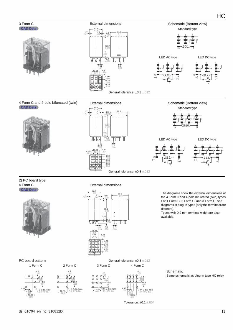
2) PC board type
3 Form CCAD Data
External dimensions20.8.819
1.7.067
1.7.067
35.21.386
6.4.252
2.54.100
0.5.020
27.21.071.024
0.6
.0391
.52613.35
.1744.41
4.06
6.35
6.35
.160
.250
.250
1
4
7
13
8 9
14
5 6
2 3
General tolerance: 0.3 .012
Schematic (Bottom view)Standard type
1
14
4
7
2
5
8
3
6
9
13
LED AC type LED DC type
1413(∼)
(∼)
1
4
7
2
5
8
3
6
9
1413
(−)(+)
1
4
7
2
5
8
3
6
9
4 Form C and 4-pole bifurcated (twin)CAD Data
External dimensions
.81920.8
1.7 1.7.067 .067
35.21.386
6.4.252
2.54.100
.0391
0.5.020
27.21.071
13.35.526 .174
4.41
4.06
6.35
6.35
.160
.250
.250
.0240.6
1
5
9
13 14
6
10 11 12
7 8
2 3 4
.1754.45
General tolerance: 0.3 .012
Schematic (Bottom view)Standard type
1
14
5
9
2
6
10
3
7
11
4
8
12
13
LED AC type LED DC type
1413
(∼)(∼)
1
5
9
2
6
10
3
7
11
4
8
12
1413
(−)(+)
1
5
9
2
6
10
3
7
11
4
8
12
4 Form CCAD Data
External dimensions
.81920.8
1.7 1.7.067 .067
35.21.386
1.5
.0391
0.5.059 .020
1.07127.2
13.35.526
.1744.41
4.06
6.35
6.35
.160
.250
.250
.0240.6
1.5.059
3.5.138
.1754.45
1 2 3 4
86 75
9 10 11
13
12
14
General tolerance: 0.3 .012PC board pattern1 Form C 2 Form C 3 Form C 4 Form C
13.35.526
8.9.350
4.45.175
.1614.1
10.4.409
16.8.661
5-.079 dia.5-2 dia. hole
13.35.526
.1614.1
10.4.409
16.8.661
8-.079 dia.8-2 dia. hole 13.35
.526
.1614.1
10.4.409
16.8.661
11-2 dia. hole11-.079 dia.
13.35.526
8.9.350
4.45.175
.1614.1
10.4.409
16.8.661
14-.079 dia.14-2 dia. hole
Tolerance: 0.1 .004
The diagrams show the external dimensions of the 4 Form C and 4-pole bifurcated (twin) types.For 1 Form C, 2 Form C, and 3 Form C, see diagrams at plug-in types (only the terminals are different).Types with 0.9 mm terminal width are also available.
SchematicSame schematic as plug-in type HC relay
HC
14 ds_61C04_en_hc: 310812D
3) TM type
With diode type (For DC)Same dimensions as HC relay standard/plug-in type
With CR circuit typePlug-in type
4 Form CCAD Data
External dimensions20.6
34.21.346
6.4.252
2.54.100
.0391
0.5.020
43.811 1.693
2.079
13.35.526
.1704.31
.1604.06
6.35
6.35.250
.250
.1754.45
.1423.6
271.063
37.61.480
1
5
9
13
6
10
2 3
7
11
4
8
12
14
General tolerance: 0.3 .012
The diagrams show the external dimensions of the 4 Form C and 4-pole bifurcated (twin) types.For 1 Form C, 2 Form C, and 3 Form C, see diagrams at plug-in types (only the terminals are different).
Chassis (Panel) cutout
Tolerance: 0.1 .004SchematicSame schematic as plug-in type HC relayBe aware that there is no LED indicator with CR circuit and built-in diode types.
37.61.480
2-.142 dia.2-3.6 dia.
Chassis (Panel) cutout in tandem mounting
Notes: 1. In mounting, use M3 screws and M3 washers.2. When mounting TM types, use washers to prevent damage or distortion to the polycarbonate cover.3. When tightening fixing screws, the optimum torque range should be 0.294 to 0.49 N·m, (3 to 5 kgf·cm).
Moreover, use washers to prevent loosening.
37.61.480
21 21.827 .827
.90623
2.079
CAD Data SchematicWithout LED indicator
1 2 3 4
5 6 7 8
9 10 11 12
13− +14
Protection (surge-absorbing) diode
With LED indicator
1 2 3 4
5 6 7 8
9 10 11 12
13− +14
Protection (surge-absorbing) diode
LED
CAD Data 4 Form C External dimensions
General tolerance: 0.3 .012
1 2 3 4
5 6 7 8
9
13
10 11 12
14
4.41
6.35
4.06
6.35
.174
.250
.160
.250
.52613.35
4.45.175
2.54.100
27.4211.079.827
52.32.059
.0391
0.5.020
6.4.252
SchematicWithout LED indicator With LED indicator
1 2 3 4
5 6 7 8
9 10 11 12
13 14
1 2 3 4
5 6 7 8
9 10 11 12
13 14
Diagrams show the external dimensions and schematic of the 4 Form C and 4-pole bifurcated (twin) types. For the 1 Form C, 2 Form C, and 3 Form C types, only the terminals differ. The dimensions of the terminal are the same as for standard type HC relays.
HC
15ds_61C04_en_hc: 310812D
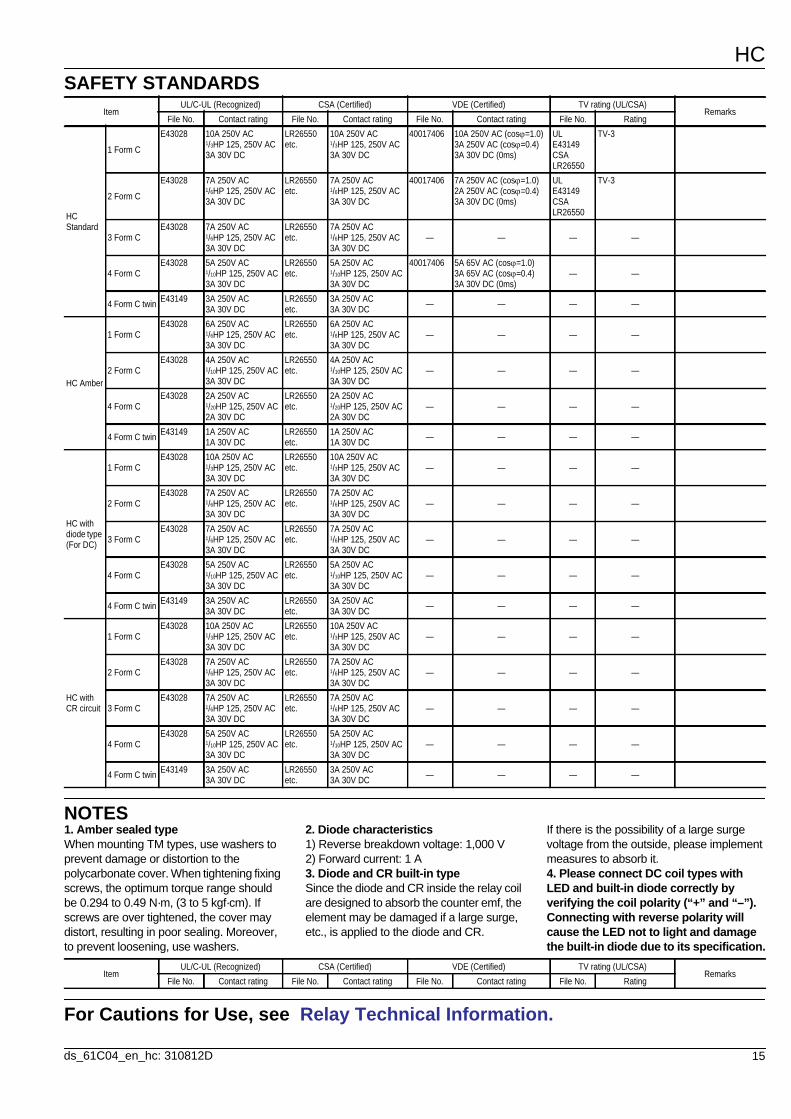
SAFETY STANDARDS
NOTES
For Cautions for Use, see Relay Technical Information.
ItemUL/C-UL (Recognized) CSA (Certified) VDE (Certified) TV rating (UL/CSA)
RemarksFile No. Contact rating File No. Contact rating File No. Contact rating File No. Rating
HC Standard
1 Form C
E43028 10A 250V AC1/3HP 125, 250V AC3A 30V DC
LR26550 etc.
10A 250V AC1/3HP 125, 250V AC3A 30V DC
40017406 10A 250V AC (cos=1.0)3A 250V AC (cos=0.4)3A 30V DC (0ms)
ULE43149CSALR26550
TV-3
2 Form C
E43028 7A 250V AC1/6HP 125, 250V AC3A 30V DC
LR26550 etc.
7A 250V AC1/6HP 125, 250V AC3A 30V DC
40017406 7A 250V AC (cos=1.0)2A 250V AC (cos=0.4)3A 30V DC (0ms)
ULE43149CSALR26550
TV-3
3 Form CE43028 7A 250V AC
1/6HP 125, 250V AC3A 30V DC
LR26550 etc.
7A 250V AC1/6HP 125, 250V AC3A 30V DC
— — — —
4 Form CE43028 5A 250V AC
1/10HP 125, 250V AC3A 30V DC
LR26550 etc.
5A 250V AC1/10HP 125, 250V AC3A 30V DC
40017406 5A 65V AC (cos=1.0)3A 65V AC (cos=0.4)3A 30V DC (0ms)
— —
4 Form C twin E43149 3A 250V AC3A 30V DC
LR26550 etc.
3A 250V AC3A 30V DC — — — —
HC Amber
1 Form CE43028 6A 250V AC
1/6HP 125, 250V AC3A 30V DC
LR26550 etc.
6A 250V AC1/6HP 125, 250V AC3A 30V DC
— — — —
2 Form CE43028 4A 250V AC
1/10HP 125, 250V AC3A 30V DC
LR26550 etc.
4A 250V AC1/10HP 125, 250V AC3A 30V DC
— — — —
4 Form CE43028 2A 250V AC
1/20HP 125, 250V AC2A 30V DC
LR26550 etc.
2A 250V AC1/20HP 125, 250V AC2A 30V DC
— — — —
4 Form C twin E43149 1A 250V AC1A 30V DC
LR26550 etc.
1A 250V AC1A 30V DC — — — —
HC with diode type (For DC)
1 Form CE43028 10A 250V AC
1/3HP 125, 250V AC3A 30V DC
LR26550 etc.
10A 250V AC1/3HP 125, 250V AC3A 30V DC
— — — —
2 Form CE43028 7A 250V AC
1/6HP 125, 250V AC3A 30V DC
LR26550 etc.
7A 250V AC1/6HP 125, 250V AC3A 30V DC
— — — —
3 Form CE43028 7A 250V AC
1/6HP 125, 250V AC3A 30V DC
LR26550 etc.
7A 250V AC1/6HP 125, 250V AC3A 30V DC
— — — —
4 Form CE43028 5A 250V AC
1/10HP 125, 250V AC3A 30V DC
LR26550 etc.
5A 250V AC1/10HP 125, 250V AC3A 30V DC
— — — —
4 Form C twin E43149 3A 250V AC3A 30V DC
LR26550 etc.
3A 250V AC3A 30V DC — — — —
HC with CR circuit
1 Form CE43028 10A 250V AC
1/3HP 125, 250V AC3A 30V DC
LR26550 etc.
10A 250V AC1/3HP 125, 250V AC3A 30V DC
— — — —
2 Form CE43028 7A 250V AC
1/6HP 125, 250V AC3A 30V DC
LR26550 etc.
7A 250V AC1/6HP 125, 250V AC3A 30V DC
— — — —
3 Form CE43028 7A 250V AC
1/6HP 125, 250V AC3A 30V DC
LR26550 etc.
7A 250V AC1/6HP 125, 250V AC3A 30V DC
— — — —
4 Form CE43028 5A 250V AC
1/10HP 125, 250V AC3A 30V DC
LR26550 etc.
5A 250V AC1/10HP 125, 250V AC3A 30V DC
— — — —
4 Form C twin E43149 3A 250V AC3A 30V DC
LR26550 etc.
3A 250V AC3A 30V DC — — — —
ItemUL/C-UL (Recognized) CSA (Certified) VDE (Certified) TV rating (UL/CSA)
RemarksFile No. Contact rating File No. Contact rating File No. Contact rating File No. Rating
1. Amber sealed typeWhen mounting TM types, use washers to prevent damage or distortion to the polycarbonate cover. When tightening fixing screws, the optimum torque range should be 0.294 to 0.49 N·m, (3 to 5 kgf·cm). If screws are over tightened, the cover may distort, resulting in poor sealing. Moreover, to prevent loosening, use washers.
2. Diode characteristics1) Reverse breakdown voltage: 1,000 V2) Forward current: 1 A3. Diode and CR built-in typeSince the diode and CR inside the relay coil are designed to absorb the counter emf, the element may be damaged if a large surge, etc., is applied to the diode and CR.
If there is the possibility of a large surge voltage from the outside, please implement measures to absorb it.4. Please connect DC coil types with LED and built-in diode correctly by verifying the coil polarity (“+” and “–”). Connecting with reverse polarity will cause the LED not to light and damage the built-in diode due to its specification.
HC
16 ds_61C04_en_hc: 310812D
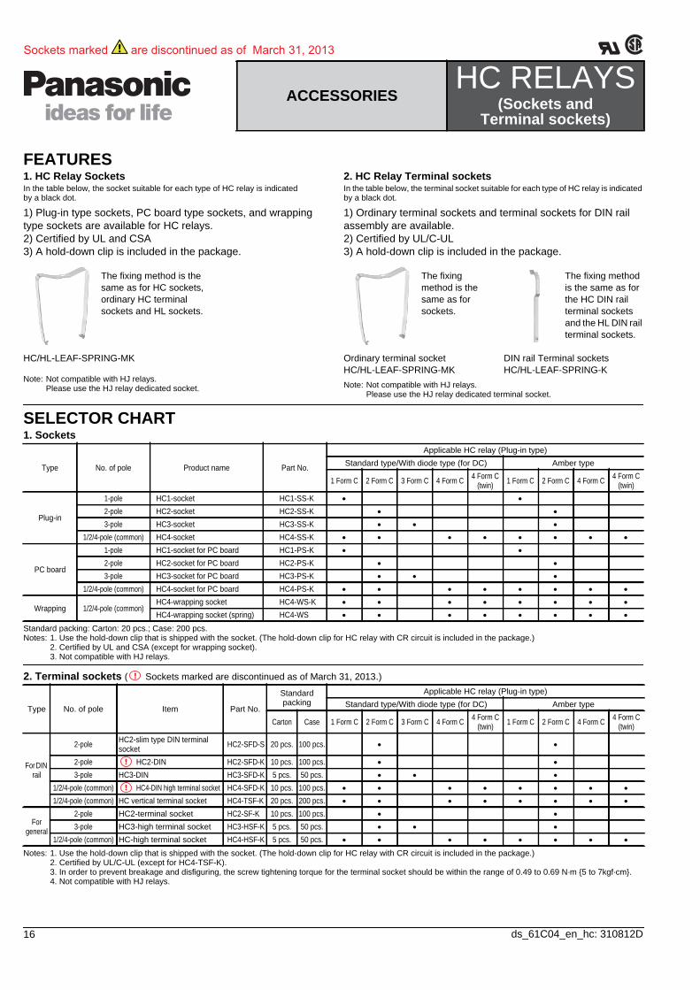
SELECTOR CHART1. Sockets
Standard packing: Carton: 20 pcs.; Case: 200 pcs.Notes: 1. Use the hold-down clip that is shipped with the socket. (The hold-down clip for HC relay with CR circuit is included in the package.)
2. Certified by UL and CSA (except for wrapping socket).3. Not compatible with HJ relays.
2. Terminal sockets ( Sockets marked are discontinued as of March 31, 2013.)
Notes: 1. Use the hold-down clip that is shipped with the socket. (The hold-down clip for HC relay with CR circuit is included in the package.)2. Certified by UL/C-UL (except for HC4-TSF-K).3. In order to prevent breakage and disfiguring, the screw tightening torque for the terminal socket should be within the range of 0.49 to 0.69 N·m {5 to 7kgf·cm}.4. Not compatible with HJ relays.
ACCESSORIESHC RELAYS
(Sockets and Terminal sockets)
Type No. of pole Product name Part No.
Applicable HC relay (Plug-in type) Standard type/With diode type (for DC) Amber type
1 Form C 2 Form C 3 Form C 4 Form C 4 Form C (twin) 1 Form C 2 Form C 4 Form C 4 Form C
(twin)
Plug-in
1-pole HC1-socket HC1-SS-K
2-pole HC2-socket HC2-SS-K
3-pole HC3-socket HC3-SS-K
1/2/4-pole (common) HC4-socket HC4-SS-K
PC board
1-pole HC1-socket for PC board HC1-PS-K
2-pole HC2-socket for PC board HC2-PS-K
3-pole HC3-socket for PC board HC3-PS-K
1/2/4-pole (common) HC4-socket for PC board HC4-PS-K
Wrapping 1/2/4-pole (common) HC4-wrapping socket HC4-WS-K
HC4-wrapping socket (spring) HC4-WS
Type No. of pole Item Part No.
Standard packing
Applicable HC relay (Plug-in type) Standard type/With diode type (for DC) Amber type
Carton Case 1 Form C 2 Form C 3 Form C 4 Form C 4 Form C (twin) 1 Form C 2 Form C 4 Form C 4 Form C
(twin)
For DIN rail
2-pole HC2-slim type DIN terminal socket HC2-SFD-S 20 pcs. 100 pcs.
2-pole HC2-DIN HC2-SFD-K 10 pcs. 100 pcs.
3-pole HC3-DIN HC3-SFD-K 5 pcs. 50 pcs.
1/2/4-pole (common) HC4-DIN high terminal socket HC4-SFD-K 10 pcs. 100 pcs.
1/2/4-pole (common) HC vertical terminal socket HC4-TSF-K 20 pcs. 200 pcs.
For general
2-pole HC2-terminal socket HC2-SF-K 10 pcs. 100 pcs.
3-pole HC3-high terminal socket HC3-HSF-K 5 pcs. 50 pcs.
1/2/4-pole (common) HC-high terminal socket HC4-HSF-K 5 pcs. 50 pcs.
Sockets marked are discontinued as of March 31, 2013
FEATURES1. HC Relay SocketsIn the table below, the socket suitable for each type of HC relay is indicated by a black dot.
1) Plug-in type sockets, PC board type sockets, and wrapping type sockets are available for HC relays.2) Certified by UL and CSA3) A hold-down clip is included in the package.
The fixing method is the same as for HC sockets, ordinary HC terminal sockets and HL sockets.
HC/HL-LEAF-SPRING-MK
Note: Not compatible with HJ relays. Please use the HJ relay dedicated socket.
2. HC Relay Terminal socketsIn the table below, the terminal socket suitable for each type of HC relay is indicated by a black dot.
1) Ordinary terminal sockets and terminal sockets for DIN rail assembly are available.2) Certified by UL/C-UL3) A hold-down clip is included in the package.
Note: Not compatible with HJ relays. Please use the HJ relay dedicated terminal socket.
The fixing method is the same as for sockets.
Ordinary terminal socketHC/HL-LEAF-SPRING-MK
The fixing method is the same as for the HC DIN rail terminal sockets and the HL DIN rail terminal sockets.
DIN rail Terminal socketsHC/HL-LEAF-SPRING-K
HC
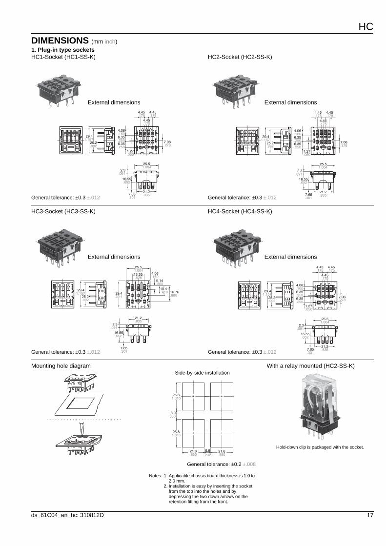
17ds_61C04_en_hc: 310812D
DIMENSIONS (mm inch)1. Plug-in type socketsHC1-Socket (HC1-SS-K)
External dimensions
1.15729.4
25.2.992
4.06.160
.175 .1754.45 4.45
.1754.45
6.35
1.27.050
6.35.250
.250
7.65.301
2.3.091
16.55.652
7.06.278
25.51.004
21.2.835
1
5
9
2
6
10
3
7
11
4
8
12
13 14
General tolerance: 0.3 .012
HC2-Socket (HC2-SS-K)
External dimensions
29.41.157
25.2.992
4.06
.175 .1754.45 4.45
.1754.45
6.35
1.27.050
6.35
.160
.250
.250
7.65.301
2.3.091
16.55.652
7.06.278
25.51.004
21.2.835
1
5
9
2
6
10
3
7
11
4
8
12
13 14
General tolerance: 0.3 .012
HC3-Socket (HC3-SS-K)
External dimensions
7.65.301
2.3.091
16.55.652
29.41.157
25.2.992
29.429.4
13.35.526
.3609.14
16.76.660
10.41.410
.1604.06
21.2.835
25.51.004
1
4
7
2
5
8
3
6
9
13 14
General tolerance: 0.3 .012
HC4-Socket (HC4-SS-K)
External dimensions
1.15729.4
25.2.992
4.06
.175 .1754.45 4.45
.1754.45
6.35
1.27.050
6.35
.160
.250
.250
7.65.301
2.3.091
16.55.652
7.06.278
25.51.004
21.2.835
1
5
9
2
6
10
3
7
11
4
8
12
13 14
General tolerance: 0.3 .012
Mounting hole diagramSide-by-side installation
General tolerance: 0.2 .008
Notes: 1. Applicable chassis board thickness is 1.0 to 2.0 mm.
2. Installation is easy by inserting the socket from the top into the holes and by depressing the two down arrows on the retention fitting from the front.
With a relay mounted (HC2-SS-K)
Hold-down clip is packaged with the socket.
8.9.350
25.8
25.8
1.016
1.016
21.6 21.6.850 .850
5.9.232
HC
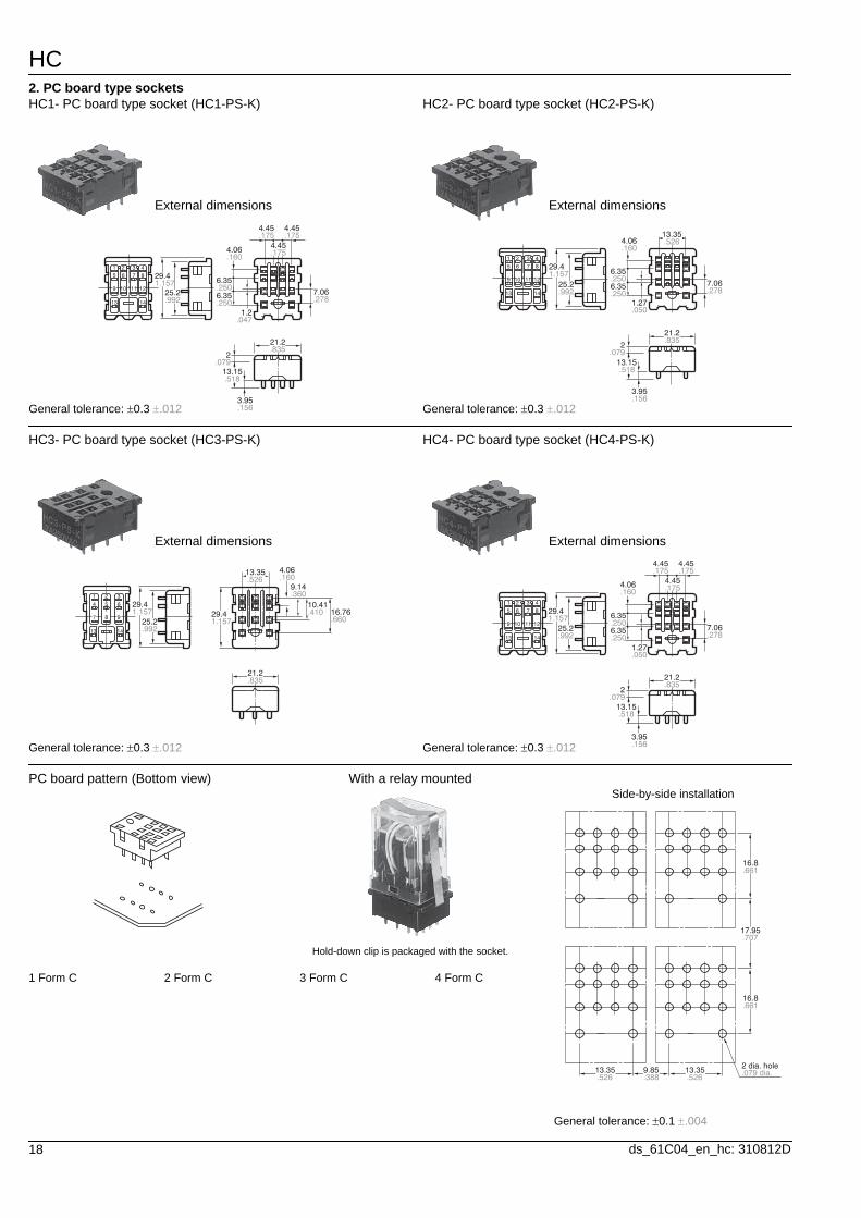
18 ds_61C04_en_hc: 310812D
2. PC board type socketsHC1- PC board type socket (HC1-PS-K)
External dimensions
29.41.157
25.2.992
.1604.06
.175 .175
.175
4.45 4.45
4.45
6.35
1.2.047
6.35.250
.250
3.95.156
2.079
13.15.518
7.06.278
21.2.835
1
5
9
2
6
10
3
7
11
4
8
12
13 14
General tolerance: 0.3 .012
HC2- PC board type socket (HC2-PS-K)
External dimensions
29.41.157
25.2.992
.1604.06
13.35.526
6.35
1.27.050
6.35.250
.250
3.95.156
2.079
13.15.518
7.06.278
21.2.835
1
5
9
2
6
10
3
7
11
4
8
12
13 14
General tolerance: 0.3 .012
HC3- PC board type socket (HC3-PS-K)
External dimensions
29.41.157
25.2.992
21.2.835
29.41.157
13.35.526
.3609.14
16.76.660
10.41.410
.1604.06
1
4
7
2
5
8
3
6
9
13 14
General tolerance: 0.3 .012
HC4- PC board type socket (HC4-PS-K)
External dimensions
1.15729.4
25.2.992
.1604.06
.175 .1754.45 4.45
.1754.45
6.35
1.27.050
6.35.250
.250
3.95.156
2.079
13.15.518
7.06.278
21.2.835
1
5
9
2
6
10
3
7
11
4
8
12
13 14
General tolerance: 0.3 .012
PC board pattern (Bottom view) With a relay mounted
Hold-down clip is packaged with the socket.
1 Form C 2 Form C 3 Form C 4 Form C
Side-by-side installation
General tolerance: 0.1 .004
13.3513.35 9.85.526.526 .388
16.8
16.8
17.95
.661
.661
.707
.079 dia.2 dia. hole
HC
19ds_61C04_en_hc: 310812D
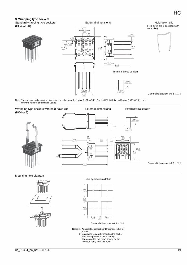
3. Wrapping type socketsStandard wrapping type sockets (HC4-WS-K)
External dimensions
16.76.660
29.41.157
25.2.992
9.14.36010.41
.410
.1604.06
12.4.488
21.2.835
1.0±0.1.039±.004
34.41.354
4.45.175
13.35.526
25.51.004
.039±.0041.0±0.1
1±0.1.039±.004
1±0.05.039±.002
Note: The external and mounting dimensions are the same for 1-pole (HC1-WS-K), 2-pole (HC2-WS-K), and 3-pole (HC3-WS-K) types. Only the number of terminals varies.
Hold-down clip(Hold-down clip is packaged with the socket)
Terminal cross section
General tolerance: 0.3 .012
Wrapping type sockets with hold-down clip (HC4-WS)
External dimensions
1.039
1.039
1
5
9
2
6
10
3
7
11
4
8
12
13 145.197
39.31.547
73.72.902
22.0.866
21.2.835
25.51.004
25.2.992
1.15729.4
.90623
1±0.1.039±.004
1±0.05.039±.002
Terminal cross section
General tolerance: 0.7 .028
Mounting hole diagramSide-by-side installation
General tolerance: 0.2 .008
Notes: 1. Applicable chassis board thickness is 1.0 to 2.0 mm.
2. Installation is easy by inserting the socket from the top into the holes and by depressing the two down arrows on the retention fitting from the front.
8.9.350
25.81.016
25.81.016
21.6 21.6.850 .850
5.9.232

HC
20 ds_61C04_en_hc: 310812D
4. DIN rail Terminal sockets ( Sockets marked are discontinued as of March 31, 2013.)HC2-Slim type DIN rail terminal sockets (HC2-SFD-S)
External dimensions
13.35±0.2.526±.008
.591±.02415±0.6
22±0.6.866±.024
28.5±0.61.122±.024
20±0.6.787±.024
6.4±0.2
.244±.0126.2±0.3
4.2±0.3.165±.012
.236±.0126±0.3
2.244±.03957±1
35.4±0.51.394±.02067±1
2.638±.0392±0.15
.079±.006
.315±.0088±0.2
6.3±0.2
.252±.008
.248±.008
.161±.0084.1±0.2
6.236
M.118 screwM3 screw
Schematic
8 5
4 1
12 9
14 13
N.C.
N.O.
COM
Coil
General tolerance: 0.5 .020
HC2-high DIN rail terminal socket (HC2-SFD-K)
External dimensions
13.35±0.2.526±.008
26±0.61.024±.024
30±0.61.181±.024
21.1±0.6.831±.024
6.4±0.2
.165±.0124.2±0.3
67±12.638±.039
2±0.15.079±.006
6.3±0.2
.252±.008
.248±.008
.161±.0084.1±0.2
6.236
M.118 screwM3 screw
Schematic
8 5
4
12
14
1
9
13
N.C.
N.O.
COM
Coil
General tolerance: 0.5 .020
HC3-high DIN rail terminal socket (HC3-SFD-K)
External dimensions
26±0.61.024±.024
30±0.61.181±.024
21.1±0.6.831±.024
6.35±0.2
.165±.0124.2±0.3
67±12.638±.0391.27±0.15
.050±.006
6.35±0.2
.250±.008
.250±.008
.160±.0084.06±0.2
6.2.244
M.118 screwM3 screw
Schematic
6
14 13
1
5
3 2
9 87
4
N.C.
N.O.
COM
Coil
General tolerance: 0.5 .020
HC4-high DIN rail terminal socket (HC4-SFD-K)
External dimensions
M.118 screwM3 screw
21.1±0.6.831±.024
67±12.638±.039
.165±.0124.2±0.3
30±0.61.181±.024
6.236
6.4±0.2
6.3±0.2
.252±.008
.248±.008
2±0.15.079±.006
.161±.0084.1±0.2
26±0.61.024±.024
4.45±0.2.175±.008
13.35±0.2.526±.008
Schematic4
8
3
7
2
6
1
5
12 11 10 9
14 13
N.C.
N.O.
COM
Coil
General tolerance: 0.5 .020
HC
21ds_61C04_en_hc: 310812D
5. Ordinary terminal sockets
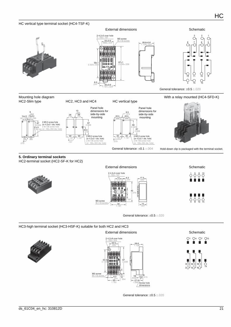
HC vertical type terminal socket (HC4-TSF-K)
External dimensions
2-.165×.1972-4.2×5 over hole
28.6±0.61.126±.024
M.118 screwM3 screw
22±0.6.866±.024
67±12.638±.039
59±12.323±.039
30±0.61.181±.024
6.2.244
Schematic
4 14 13
12 11 10 9
8 7 6 5
3 2 1
General tolerance: 0.5 .020
.886 .88622.5 22.5
592.323
672.638
30 301.181 1.181
2.079
9.5.374
2-M.138 screw hole(or .165±.004 dia. hole)
2-M3.5 screw hole(or 4.2±0.1 dia. hole)
26 261.024 1.024
33.51.319
672.638
30 301.181 1.181
10.394
4.157
2-M.138 screw hole(or .165±.004 dia. hole)
2-M3.5 screw hole(or 4.2±0.1 dia. hole)
.591±.008
2.244±.02057±0.5
672.638
2-M.138 screw hole(or .165±.004 dia. hole)
2-M3.5 screw hole(or 4.2±0.1 dia. hole)
22 22.866 .8662
.079
.3549
.591±.00815±0.2 15±0.2
Mounting hole diagramHC2-Slim type HC2, HC3 and HC4 HC vertical type
With a relay mounted (HC4-SFD-K)
Hold-down clip is packaged with the terminal socket.General tolerance: 0.1 .004
Panel hole dimensions for side-by-side mounting
Panel hole dimensions for side-by-side mounting
HC2-terminal socket (HC2-SF-K for HC2)
External dimensions
General tolerance: 0.5 .020
12.472
17.5.689
301.181
15.591
6.2.244
401.575
5.197
M.118 screwM3 screw
2-.165×.1972-4.2×5 over hole
Schematic1 5 9 13
4 8 12 14
HC3-high terminal socket (HC3-HSF-K) suitable for both HC2 and HC3
External dimensions
General tolerance: 0.5 .020
22.5.886
301.181
27.81.094
28.61.126
.63016 8
.3156.2.244
6753.52.6382.106
9.354
Screw hole dimensions
2-.165×.3542-4.2×9 over hole
M.118 screwM3 screw
Schematic1 4 7 13
3 6 9
2 5 814
HC
22 ds_61C04_en_hc: 310812D
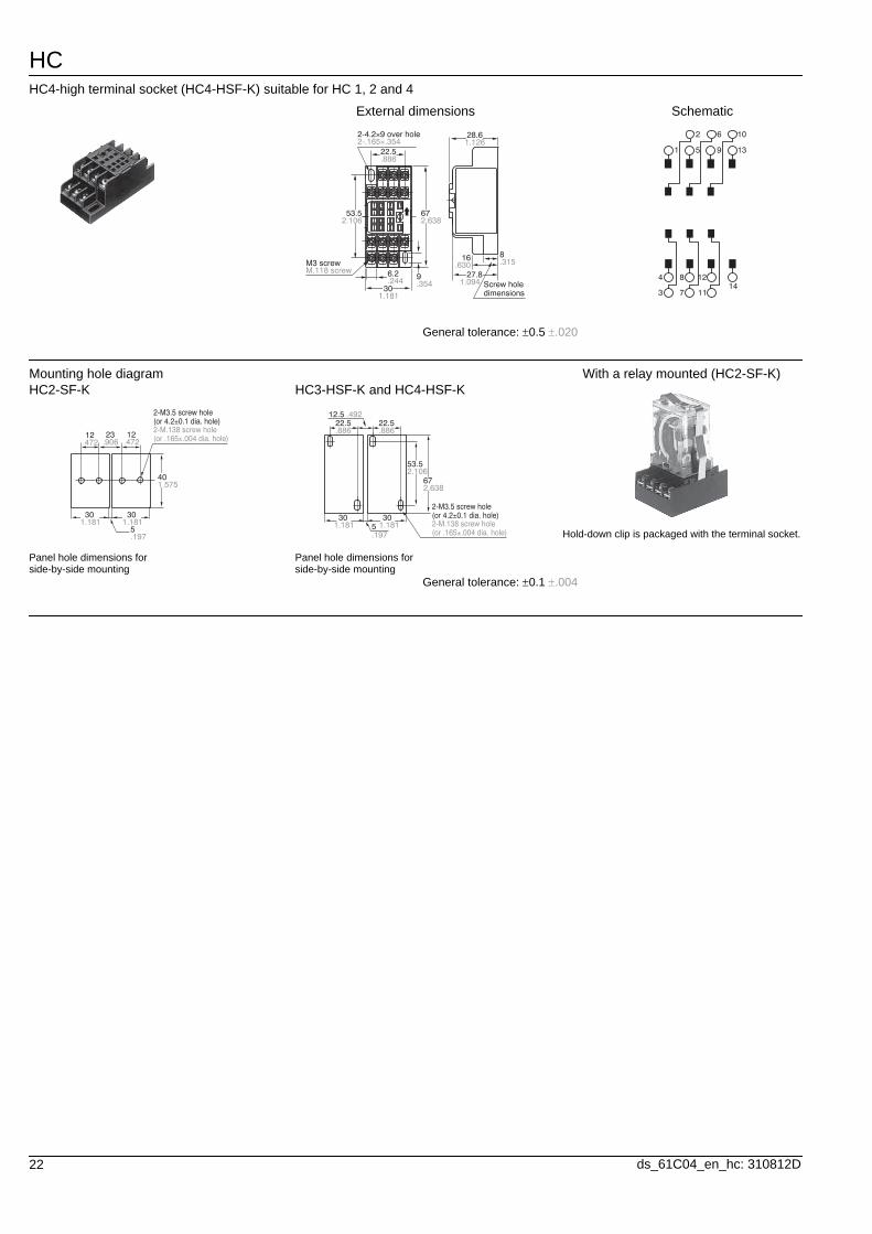
HC4-high terminal socket (HC4-HSF-K) suitable for HC 1, 2 and 4
External dimensions
General tolerance: 0.5 .020
2-.165×.3542-4.2×9 over hole
22.5.886
53.52.106
672.638
9.354
6.2.244
301.181
M.118 screwM3 screw
28.61.126
8.315.630
16
27.81.094 Screw hole
dimensions
Schematic
1
2
4
3
5
6
8
7
9
10
12
13
1411
Mounting hole diagramHC2-SF-K
Panel hole dimensions for side-by-side mounting
HC3-HSF-K and HC4-HSF-K
Panel hole dimensions for side-by-side mounting
.472 .472.90612 1223
401.575
30 301.181 1.181
5.197
2-M.138 screw hole(or .165±.004 dia. hole)
2-M3.5 screw hole(or 4.2±0.1 dia. hole) 22.5 22.5
.886 .886
53.52.106
2.63867
30 301.181 1.1815
.197
12.5 .492
2-M.138 screw hole(or .165±.004 dia. hole)
2-M3.5 screw hole(or 4.2±0.1 dia. hole)
With a relay mounted (HC2-SF-K)
Hold-down clip is packaged with the terminal socket.
General tolerance: 0.1 .004


![AIR CONDITIONING SYSTEM [50Hz] - PT. Daikin ... FLOOR STANDING TYPE COMPACT MULTI FLOW CEILING MOUNTED CASSETTE TYPE DUCT CONNECTION MIDDLE and HIGH STATIC PRESSURE TYPE lineup of](https://img.pdfslide.us/doc/110x75/5a9e90787f8b9a8e178b842a/pdfair-conditioning-system-50hz-pt-daikin-floor-standing-type-compact.jpg)