Embed Size (px)
Citation preview

825B135BSPTGauge or absolute pressure transmitters
Features
Gauge pressure: from 0,6KPa (6mbar) to 40MPa (400bar)
Absolute pressure: from 2KPa (20mbar) to 3MPa (30bar)
Power supply: 12÷42Vdc
Max. measurement accuracy: ±0,075%
Analog output resolution: 16 bit
Communication Protocol: HART
Calibration and Confi guration: with onboard buttons Data display: backlit alphanumeric display
Data Storage: su EEPROM
Housing Mechanical protection: IP67
Process Controll and Measurement
Factory Test Certifi cateIn conformity to the company and check procedures I certify that the equipment:
SPT................... Production and check date: ................................
Serial n. .......................................................
is conform to the technical requirements on Technical Data and it is made in conformity to the SGM-LEKTRA procedure
Quality Control Manager .................................
WarrantyProducts supplied by SGM LEKTRA are guaranteed for a period of 12 (twelve) months from delivery date according to the conditions specifi ed in our sale conditions document.SGM LEKTRA can choose to repair or replace the Product.If the Product is repaired it will mantein the original term of guarantee, whereas if the Product is replaced it will have 12 (twelve) months of guarantee.The warranty will be null if the Client modifi es, repair or uses the Products for other purposes than the normal conditions foreseen by instructions or Contract.In no circumstances shall SGM LEKTRA be liable for direct, indirect or consequiential or other loss or damage whether caused by negligence on the part of the company or its employees or otherwise howsoever arising out of defective goods

Pag.2 of 20
SPT - Operation
1. Operating Principles1.1 - Pressure sensorThe SPT sensor module key element is shown in Fig.1-2.
The differential pressure transmitter includes two functional units: the main unit and the auxiliary unit.The main unit includes the process connection and the sensor. The chip side opposite to the pressure to be measu-red, is connected to atmospheric pressure (gauge pressure measurement) or to the vacuum cell (absolute pressure). The applied pressure on the measuring diaphragm, transmitted to the silicon chip through the fi lling liquid, changes the chip electrical resistance with consequent variation of the pressure detection system output voltage. This voltage variation is then translated into a 4-20mA current output variation.
1.2 - Temperature Compensation The SPT is able to compensate the possible measurement deviations caused by temperature variations.The temperature detection circuit, located inside the A/D converter, sends to the microprocessor the information neces-sary to process the measured value adjustment of the differential pressure in relation to the temperature change (∆T).
1.3 - A/D converter A/C converter converts the analog signal to digital signal, which is then input into the microprocessor.
The resolution is 16 bit
Fig.1-2
Compact digital system, 12÷45Vdc 2-wire technology, suitable for liquid, gas and steam applications.
Ranges from 0,6 KPa to 40MPa
Thanks to the automatic measure compensation, according to the operating temperature variation, the SPT pressure transmitters series has the feature to maintain this its stability and its accuracy constant over time. The SPT series industrial sectors application are several: steel industry, pharmaceutical, food and other. The process pressure is transmitted, through the isolating diaphram and the oil fi ll, to the sensitive silicon chip placed in the sensor center. In the same way the reference pressure is transmitted to the opposite side of the sensing diaphram. Il diaframma sensibile viene quindi fl esso in modo proporzionale alle pressioni applicate. The sensitive diaphragm bending originates a resistivity variation of the silicon chip that produces a reference voltage variation. The voltage difference gene-rated by the sensor is converted into a two-wire 4÷20mA analog signal and, by means of a modulation, the standard HART bidirectional communication is possible.
Confi guration and calibration via onboard displayor via HART software
Accuracy: ±0.075%

Pag.3 of 20
1.4 - Microprocessor The microprocessor performs the following operations: - controls the A/D and D/A conversion; - provides self-diagnosis; - performs digital communication; - manages the linearization, range and system integration data.
1.5 - Memory The system confi guration parameters are stored in EEPROM, so that the stored data is not lost in case of supply voltage interruption.
1.6 - D/A converterThe D / A converter transduces the digital signal from the microprocessor, into a 4÷20mA analog output signal.
1.7 - Digital Communication The SPT transmitters are tested and calibrated using a portable or fi xed programmer, supported by the HART Com-munication Protocol. The HART protocol applies the industry standard. The digital signal (1200÷2200Hz) overlapped on 4÷20 analog signal will not affect 4÷20 mA process signal.
SPT - Operation/Technical data
2. Technical data
2.1 - ApplicationsThe SPT series is applicable in pressure measurements of liquids, gases and vapors.
2.2 - Operation rangeThe operation ranges are in used cell function in the SPT series specifi c model, as reported in the following table:
RangeCode Measurement range Range limits
Accuracy±0.075% (cod. H)
B 0÷ 0,60...6KPa (0÷60...600mmH2O) (0÷6...60mbar) gauge p. -6 ÷ +6 kPa D
C 0÷ 2...40KPa (0÷20...4000mmH2O) (0÷20...400mbar) gauge p. -40 ÷ +40 kPa D
D 0÷ 2,5...250KPa (0÷0.25...25mH2O) (0÷25...2500mbar) gauge p. -100 ÷ +250 kPa D
F 0÷ 30KPa...3MPa (0÷3...300mH2O) (0÷0,3...30bar) gauge p. -100 ÷ +3000 kPa D
G 0÷ 0,1...10MPa (0÷10...1000mH2O) (0÷1...100bar) gauge p. -0.1 ÷ +10 MPa D
H 0÷ 0,21...21MPa (0÷21...2100mH2O) (0÷2,1...210bar) gauge p. -0.1 ÷ +21 MPa D
I 0÷ 0,4...40MPa (0÷40...4000mH2O) (0÷4...400bar) gauge p. -0.1 ÷ +40 MPa D
L 0÷ 2...40KPa (0÷200...4000mmH2O) (0÷20...400mbar) p. relativa 0 ÷ +40 kPa D
M 0÷ 2,5...250KPa (0÷0.25...25mH2O) (0÷25...2500mbar) absolute p. 0 ÷ +250 kPa D
O 0÷ 30KPa...3MPa (0÷3...300mH2O) (0÷0.3...30bar) absolute p. 0 ÷ +3000 kPa D
Note: D, available; N, unavailable. Tab.2-1

Pag.4 of 20
2.3 - Output Signal4-20mA analog signal with two-wire connection and digital communication with HART protocol.
2.4 - Power supplyStandard 24Vdc, 12÷45Vdc taking account of the load applied to the output signal, as shown in Fig. 2-1
2.5 - Output signal loadThe maximum applicable load value to the output signal is a function of the supply voltage applied, as shown in fi g 2-1. The maximum applicable load value is provided by the following mathematical formula:
RL = ( Vs - 12Vdc ) / 23mA ; RL, maximum load; Vs, supply voltage applied.
2.7 - Zero and Span calibrationThe zero and span calibration can be performed using the on-board buttons, or via HART communication.
2.8 - Positive and negative OFFSET- Differential pressure transmitter:
The max. positive OFFSET is the difference between the upper value limit and the measure range > URL (upper range limit)
- Gauge pressure transmitter: The max. positive OFFSET is the difference between the URL and the measure range. The max. negative OFFSET is > than 1 Atm- Absolute pressure transmitter:
The max. OFFSET i s the difference between the URL and the measured range. The negative OFFSET does not exist.
2.9 - AlarmsA self-diagnostic program detects a problem when the output signal is higher than 20,8 mA or lower than 3.8 mA.
Both values are confi gurable by the user through the on-board push buttons.
2.6 - DisplayField display for current output, 0-100%, engineering units with LCD backlit display
SPT - Technical data
Fig.2-1
Operation status
engineering unitsanalog output percentage bar graph
measured value
Pag.5 of 20
SPT - Technical data
2.10 - Temperature rangesElectronic unit: -40°C ÷ +85°C
Electronic unit with LCD display and Viton seals: -20°C ÷ +65°C
2.11- Storage Temperature-50°C ÷ +85°C; electronic unit with LCD display: -40°C ÷ +65°C
2.12 - Starting time (Warm-up)maximum 15s.
2.15- Accuracy±0,075%
2.16 - Stability±0.1%
2.17 - Temperature driftTotal error ±0.08% of the maximum range value, every 10°C
2.18 - Static pressure drift±(0,05%URL + 0.075%Span)/10MPa
2.19 - Massima pressioneThe maximum pressure values change as a function of the ordered code: “B/C/L” - 1MPa “D/M” - 4MPa “F/O” - 15MPa “G” - 20MPa “H/I” - 50MPa
2.20 - Overpressure effect±0.1% x Span / 10MPa
2.21 - Installation position infl uenceZero deviation up to 0.4KPa, adjustable via calibration, for rotations of 90° relative to the sensor diaphragm plane.
2.22 - Materiali di costruzioneSensor body: SS316L
Flanges: SS316L
Isolating diaphragm according to the model: SS316L; Hastelloy C;
Nuts and bolts: SS304
Process connections: SS316
Filling fl uid according to the model: silicone oil, fl uorinated oil
Seals in the process according to the model: NBR (nitrile rubber Perbunan®); FKM (Viton); PTFE (tefl on)
Electronics housing: aluminum with epoxy paint
Electronics housing seals: NBR (nitrile rubber Perbunan®)
Unit code nameplate: SS304

Pag.6 of 20
SPT - Technical data
2.23 - Process Connections
1/2NPT1/4NPT
20.7
1/2 NPT
M20x1.5
20
G1/2
20
Ø30
20
1/4NPT
20
1/2 “NPT female threaded (cod.1 std.). Version for range cod. F/G/H/I/O
1/2 NPT
O-ring( Look additional options)
1/2 “NPT female threaded (cod.1 std.). Version for range cod. B/C/D/L/M
1/2“ NPT male thread with 1/4“ NPT female threaded hole (cod.2 std.)
M20x1.5 male threaded (cod.3 std.)
1/2” G male threaded (cod.4 std.)
Vacuum connection ISO 2861; max.2.5bar (cod.5 opz.)
1/4”NPT male thread (cod.6 std.)

Pag.7 of 20
SPT - Mechanical Installation
Fig.3-2
Fig.3-1
Fig.3-3
3.1.2 - Mounting on vertical 2“ pipe (Fig. 3-2) and wall mount (Fig. 3-3)
3. Mechanical Installation
3.1 - Mounting on 2“ pipe or wall mounted - Option 1/2
3.1.1 - Mounting on horizontal 2“ pipe (Fig. 3-1) and mechanical dimensions
2.24 - Electrical connections M20x1.5 cable glands. Grounding terminal for cables up to 2.5mm2
2.25- Weight1.6Kg excluding accessories
Pag.8 of 20
Fig.4-1
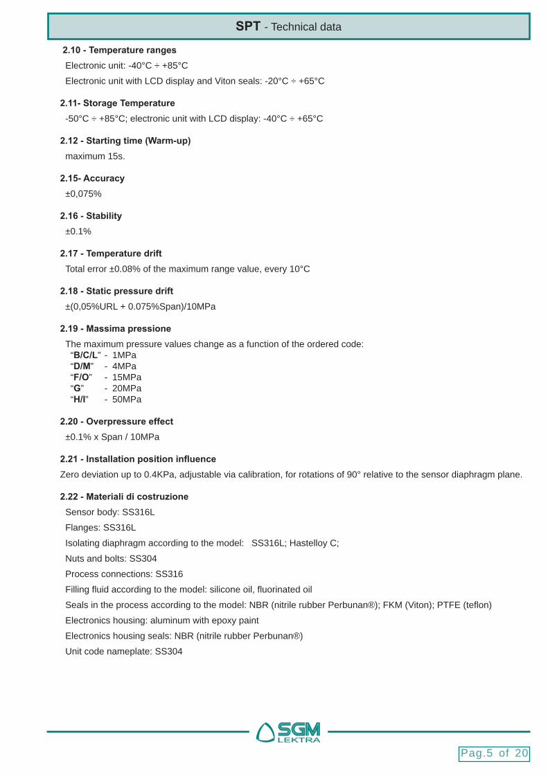
4 - Setup4.1 Calibrations via Z and S buttons
The units are manufactured with default confi gurations. In the absence of a Hand Held Communicator or of a PC SW or of the display, to change the calibrations operate on the keys as shown below.
4.1.1 Range calibrationPress S+Z for 5 sec.
Apply the minimum pressure; hold down the Z button for 5 seconds until the current signal is automatically adjusted to 4mA (0%)
Apply the maximum pressure; hold down the S button for 5 seconds until the current signal is automatically adjusted to 20mA (100%)
4.2 Operating menuWhen the unit SPT is equipped with its display (cod.1/2 opt.), is possible to confi gure and calibrate the SPT unit accessing the operating menu. The operating menu structure is shown in Fig. 4-1.
SPT - Setup

Pag.9 of 20
SPT - Setup
4.3 Access to the operating menu When switched on, the display shows the start-up message system
Fig.4-2
Completed the boot process, the unit SPT will be set automatically in RUN mode, displaying the measurement of differential pressure as previously set.
To access the operating menu, press the Z and S simultaneously (fi g. 4-2).
After the S and Z release, the word EXIT will be displayed.The below bar graph will continue to show the percentage value of the measuring range. N.B. - After about 60 seconds, in the commands with Z and S absence, the system will automatically return to RUN mode..
Press S to scroll to the next parameter;
Press Z to scroll to the previous parameter;
Z e S contemporaneamente per uscire dal menù operativo
N.B. - The exit from the operating menu, by pressing Z and S at the same time, is possible only by the EXIT parameter.

Pag.10 of 20
SPT - Setup
With Z or S select the pressure measure unit.The available units measurement are:
inH2O - inHg - ftH2O - mmH2O - mmHg - psi - bar - mbar - g/cm2 -
Kg/cm2 (abbreviated as kg/c2) - Pa - kPa - torr - ATM - MPa
4.3.3 UNIT Unità di misura della pressionePress: Z and S at the same time to access the parameter;S to scroll to the next parameter; Z to scroll to the previous parameter;
Press 2 times Z and S at the same time to confi rm the selection and exit the parameter
With Z or S select the analog output mode:LINEAR - linear analog output, the choice is highlighted on the display by the “/” symbol
4.3.2 FUNCTION 4÷20mA analog output modePress: Z and S at the same time to access the parameter;S to scroll to the next parameter; Z to scroll to the previous parameter;
SQUARE ROOT - uscita analogica sotto radice quadrata, the choice is highlighted on the display by the “ ” symbol
Press 2 times Z and S at the same time to confi rm the selection and exit the parameter
4.3.1 SOFT VER Software versionPress: Z and S at the same time to access the parameter;S to scroll to the next parameter; Z to scroll to the previous parameter;
Displaying data of the SPT software version.Press Z and S at the same time to exit the parameter
Pag.11 of 20
SPT - Setup
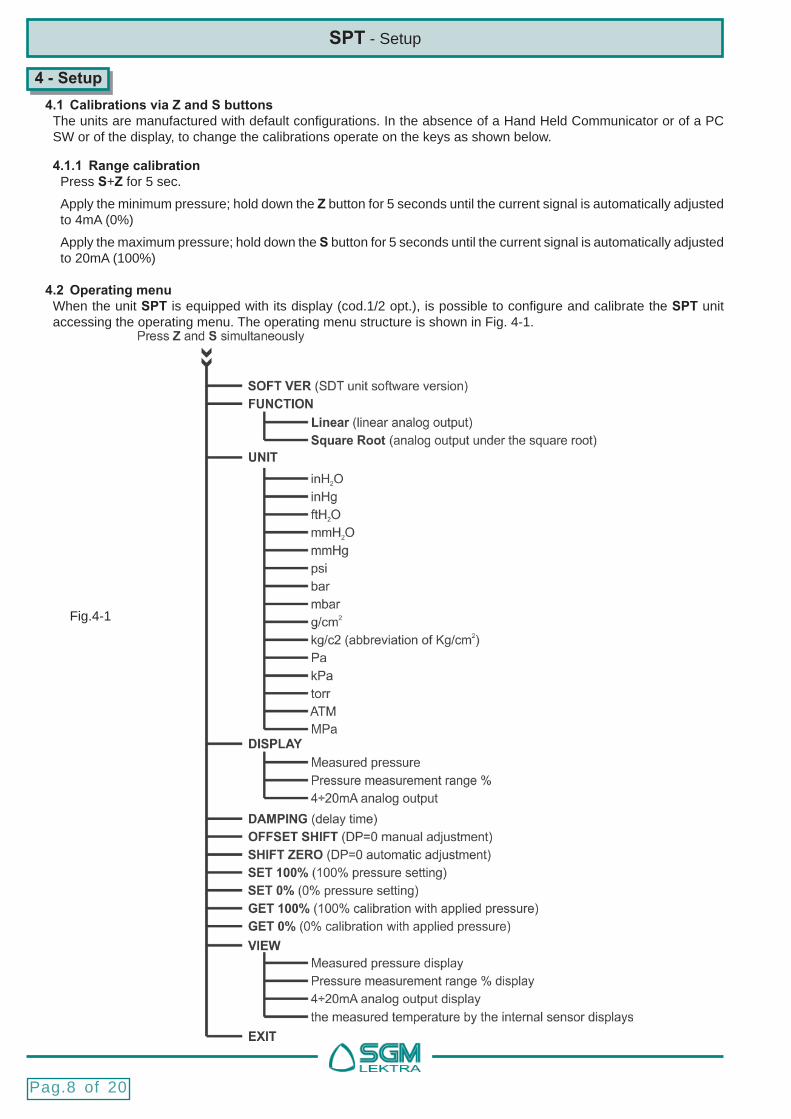
With Z or S select the measurement to be displayed during RUN mode:Is possible to select:- measured pressure with its measurement unit; the choice is highlighted on the display with the number 1 on the bottom left
4.3.4 DISPLAY Selecting the displaying in RUN mode.Press: Z and S at the same time to access the parameter;S to scroll to the next parameter; Z to scroll to the previous parameter;
- 4÷20mA analog output signal value; the choice is highlighted on the display with the number 3 on the bottom left
- range percentage of the pressure measurement; the choice is highlighted on the display with the number 2 on the bottom left
Press 2 times Z and S at the same time to confi rm the selection and exit the parameter
With S move the cursor to select the digit.With Z change the digit.
4.3.5 DAMPING Delay time, in seconds, for the reading variations the of the pressure measurement.Press: Z and S at the same time to access the parameter;S to scroll to the next parameter; Z to scroll to the previous parameter;
Press 2 times Z and S at the same time to confi rm the selection and exit the parameter
In the event that the value entered is not correct, will be displayed the error message and the parameter will not be modifi ed.Press Z and S at the same time to exit the parameter

Pag.12 of 20
SPT - Setup
With S move the cursor to select the digit.With Z change the digit.Es.: range 0÷100kpa; OFFSET +5% = new range -5÷+95kPaEs.: range 0÷100kpa; OFFSET -5% = new range +5÷105kPaEs.: range -100÷100kpa; OFFSET +55% = new range -110÷90kPa Es.: range -100÷100kpa; OFFSET -55% = new range -90÷110kPa
4.3.6 OFFSET SHIFT P zero offset Manual adjustment. Adjustment Range: -12.00% ÷ +12.00% on the range percentage corresponding to P zeroPress: Z and S at the same time to access the parameter;S to scroll to the next parameter; Z to scroll to the previous parameter;
Press 2 times Z and S at the same time to confi rm the selection and exit the parameter.N.B. - This function is useful for manually correct the measurement offset caused by the mounting position (eg sensor inclined), when it is not possible to apply to the cells the P zero pressure
In the event that the value entered is not correct, will be displayed the error message and the parameter will not be modifi ed.Press Z and S at the same time to exit the parameter
4.3.7 SHIFT ZERO P zero offset automatic adjustment. Press: Z and S at the same time to access the parameter;S to scroll to the next parameter; Z to scroll to the previous parameter;
Press Z and S at the same time to exit the parameterN.B. - This function is useful to automatically correct the offset measurement caused by the mounting position (eg sensor inclined),when is possible to apply to cells the P zero pressure
With S move the cursor to select the digit.With Z change the digit.N.B. - The displayed measure unit depending on the UNIT parameter setting in section 4.3.3
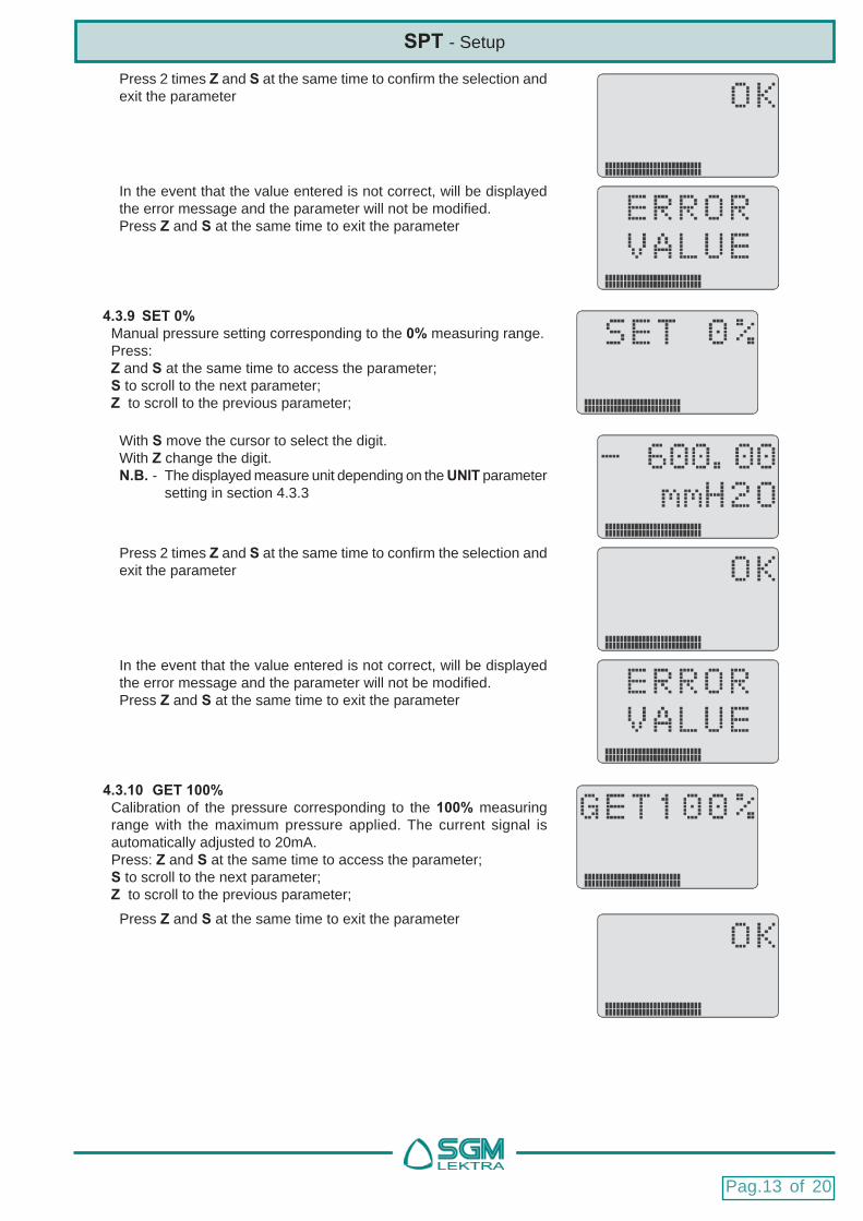
4.3.8 SET 100% Manual pressure setting corresponding to the 100% measuring range.Press: Z and S at the same time to access the parameter;S to scroll to the next parameter; Z to scroll to the previous parameter;
Pag.13 of 20
SPT - Setup
Press 2 times Z and S at the same time to confi rm the selection and exit the parameter
In the event that the value entered is not correct, will be displayed the error message and the parameter will not be modifi ed.Press Z and S at the same time to exit the parameter
With S move the cursor to select the digit.With Z change the digit.N.B. - The displayed measure unit depending on the UNIT parameter setting in section 4.3.3
4.3.9 SET 0% Manual pressure setting corresponding to the 0% measuring range.Press: Z and S at the same time to access the parameter;S to scroll to the next parameter; Z to scroll to the previous parameter;
Press 2 times Z and S at the same time to confi rm the selection and exit the parameter
In the event that the value entered is not correct, will be displayed the error message and the parameter will not be modifi ed.Press Z and S at the same time to exit the parameter
4.3.10 GET 100% Calibration of the pressure corresponding to the 100% measuring range with the maximum pressure applied. The current signal is automatically adjusted to 20mA. Press: Z and S at the same time to access the parameter;S to scroll to the next parameter; Z to scroll to the previous parameter;
Press Z and S at the same time to exit the parameter

Pag.14 of 20
4.3.11 GET 0% Calibration of the pressure corresponding to the 0% measuring range with the minimum pressure applied. The current signal is automatically adjusted to 4mA. Press: Z and S at the same time to access the parameter;S to scroll to the next parameter; Z to scroll to the previous parameter;
Press Z and S at the same time to exit the parameter
With Z or S select the measurement to be displayed:Is possible to select:- measured pressure with its measurement unit; the choice is highlighted on the display with the number 1 on the bottom left
4.3.12 VIEW Measurement display without changing the display in RUN mode (DISPLAY parameter, 4.3.4).Press: Z and S at the same time to access the parameter;S to scroll to the next parameter; Z to scroll to the previous parameter;
- range percentage of the pressure measurement; the choice is highlighted on the display with the number 2 on the bottom left
- 4÷20mA analog output signal value; the choice is highlighted on the display with the number 3 on the bottom left
- temperature measured by the sensor inside the cell; the choice is highlighted on the display with the number 4 on the bottom left
- Parameter for the headquarters exclusive use
- Not active function
SPT - Setup

Pag.15 of 20
6. InstallationSPT transmitters can be used for fl ow, liquid level, or other applications requiring accurate measurement of pressure. The accuracy of a measurement depends to a great extent on proper installation of the SPT and impulse piping, so that correct installation is very important. The transmitters are often installed in harsh environments due to process and economic consideration. Thus the transmitters should be located to minimize the effects of temperature gradients and fl uctuations and to avoid vibration and mechanical shock.
! CAUTION !It is not allowed for the medium to ice because it would damage the isolating diaphragm,
and destroy the transmitter
6.1 - Process ConnectionThe following information is very important for properly mounting a transmitter..
6.1.1 - Location Proper transmitter location with respect to the process pipe depends on the process material. Consider the following to determine the best location:
a) Keep corrosive of hot process material away from the transmitter
b) Avoid sediment deposit in the impulse piping
c) Keep connection piping as short as possible
d) Install connection piping at temperature gradients and fl uctuations less changing place. Keep connection piping
Press 2 times Z and S at the same time to confi rm the selection and exit the parameter
- Parameter for the headquarters exclusive use
- Parameter for the headquarters exclusive use
SPT - Setup/ Installation
Pag.16 of 20
SPT - Installation
6.1.2 - Error minimization The connecting pipes between the process and the transmitter transmit the pressure between the two points. The following conditions may cause transmission pressure errors:
1) Line losses
2) Line resistances caused by: bottlenecks; valves separation; the insuffi cient transducer/process pipes connecting diameter 3) Fluid presence in a gas line
4) Gas presence in a fl uid line
5) Variations in product density between the transmitter and the process connection
To minimize the error take the following steps:
1) The transducer/process pipes connecting length the must be reduced to a minimum
2) For gas, the tubes connection the transducer / process must have a positive slope at least 1/12 toward the process connection
3) For liquids and vapor, the transducer/process connecting pipes should have the negative slope at least 1/12 toward the process connection
4) Avoid the following line points: high for liquids lower for gas
5) Maintain a constant temperature between the transmitter and the process connection
6) Use connecting pipes with a suffi cient diameter to prevent the line resistance
7) Bleed the presence of any gas from the pipes with fl uid
8) Fill the transducer/process connecting pipes at the same level, when using a liquid separation in the gas lines
9) Avoid purging through the transmitter. Make the purge connection close to the process taps and purge through equal lengths of the same size pipe
6.2 - Mechanical mountingSPT transmitters can be mounted directly at the point of measurement, can be mounted against a wall, or with the use of a mounting bracket- to a 2’’ (about Ø60 mm) pipe.
6.3 - Electrical connectionsThe connection terminal is housed in the transmitter housing separate compartment. Unscrew the cover placed over the “FIELD TERMINALS” word to access the terminal. For the electrical connection, the analog signal cables is suffi cient, because the SPT is a transmitter with two-wire technology. The connection cable must be a shielded twisted pair cable with a cross section of 2x0.5m2 also not be channeled with power cables.The cable glands for cable entry to the transmitter housing should be sealed or blind (M20x1.5) with a sealant to prevent the ingress of humidity into the housing. If the connection is not tight, the cable gland must be facing down to allow drainage of any condensation forming.The electrical signal may be transmitter or ungrounded.

Pag.17 of 20
WARNING - Because the transmitter is capacitance-coupled to ground, insulation resistance should not be checked with high voltage meter. No more than 45V should be used for circuit check.
SPT - Installation
7. Maintenance
Normally frequent system maintenance works are not necessary, because in the transmitter SPT there are no moving parts.This section describes:
- The test methods for the sensor
- The procedure to disassemble the transmitter
- The procedure to assemble the transmitter
7.1 - Sensor TestIf there is a infi ltration of liquid, or insulation diaphragm is damaged, the sensor must be replaced. The sensor replacement operation can not be performed in the fi eld, for which it is necessary disassembling the transmitter and perform the failure sensor replacement operation in a adequate local.
7.2 - Disassembly Procedure 7.2.1 - Electronic parts WARNING - During the following operations take all necessary precautions to avoid electrostatic discharge and make sure that the transmitter does not have the power supply switched on.
1) Unscrewing the two screws on the cover of the display, it is possible:
a) rotate the display by 90°, or 180°, or 270°
b) replace the display unit
c) replace the electronics unit
d) disconnect the fl at electrical cable between the electronic unit and the sensor
2) Unscrewing the two screws on the terminal box cover you can replace the electronic control unit integrated in the terminal box
7.2.3 - Sensor 1) Unscrew the two screws of the display cover and disconnect the electronic unit from the sensor fl at electrical cable
2) Fully unscrew the socket head placed under the “FIELD TERMINALS” word
3) Unscrew the sensor from the housing, taking care not to damage the isolation diaphragm or the fl at electrical cable to connection to the electronic unit.
4) The sensor body is a watertight block, so it is not possible to disassemble other parts of it
Fig. 6.3
Pag.18 of 20
SPT - Installation
7.3 - Reassembly procedure 7.3.1 - Preparation 1) Inspect all O-rings and replace if necessary
2) Put some silicone grease on the o-ring for a better seal
7.3.2 - Sensor 1) Insert the fl at electrical cable of the sensor into the housing
2) Put the sealant retaining compound on the sensor threads to make sure it does not happen humidity infi ltration from it
3) Screw the sensor and make sure the o-ring is in the correct position
4) Make sure that the slot found on the sensor body, for locking with the allen screw, has reached the correct positio
5) Lock the housing by tightening the socket head placed under the “FIELD TERMINALS” word.
7.3.3 - Electronic parts 1) Check that the electronic circuits are clean
2) Make sure that the the male and female connectors in the housing, and in the circuits, do not show anomalies (dirt, folds, ..)
3) Insert the sensor fl at cable connector into the connector on the electronic circuit. Observe the polarity of insertion
4) Insert the electronics in the housing, making sure that: a) the two male connectors, which are present in the housing, fi t perfectly in the two female connectors present on the electronics. Operation facilitated by the female connectors funnel shape. b) the sensor fl at cable is positioned in the housing hollow section c) the two holes for the screws are aligned with the housing threaded holes
5) Insert the display, orienting it according to the need of installation, and tighten the two screws
7.3.4 - Advice 1) The display can be rotated 90 °, 180 °, 270 ° for easy reading, as indicated in step 7.2.2/1.a
2) The o-ring seal should be checked each time a opening and/or closing maneuver is performed.
3) The display housing end cap glass should not be removed for any reason, because the warranty seal would be compromised
7.3.5 - Mechanical parts replacing All mechanical parts are replaceable without the need to recalibrate the system

Pag.19 of 20
SPT - Troubleshooting
8. Troubleshooting
he procedures described here, are used to identify the causes of system malfunction, and to suggest possible measures to be taken to eliminate the inconvenience. In the event that, after following the procedures described here, does not resolve the inconvenience, please contact our customer service.
8.1 - High analog outputThe causes and possible solutions are:
1) Check the restrictions on the primary element (eg. Holes free)
2) Check in the connection pipes that:
a) there are no sealing leak, or holes on the pipe surface or inside obstruction elements
b) check that the interception valves are fully open and the bypass valves are closed
c) there is no gas presence in the fl uid processes, and conversely, there is no fl uids presence within the gas process
d) there are no sediment deposits inside the process connection fl anges
e) that the fl uid density present in the process and the sensor is identical
3) Internal electrical connections:
a) make sure that all connection points are clean
b) make sure that the supply voltage is 12÷42Vdc
4) Faulty electronic parts:
b) replace the fault electronic component
5) Sensor module:
a) Refer to the “sensor module” section
6) Power supply unit:
a) check the supply voltage
8.2 - Low or absent analog outputThe causes and possible solutions are:
1) Primary elements:
a) check check check the primary elements installation and the conditions
b) check for any changes in process fl uid properties and the arising consequences
2) Line electrical connections (loop):
a) check the power supply
b) verify that there are no grounding points on the line (loop)
c) check the connection line polarity (loop)
!WARNING!The supply voltage must not be greater than 42V during the loop test.
3) Connecting pipes:
a) check that the pressure connection is correct
b) check that there are no leaks or occlusions
c) check that there is no gas presence within processes with fl uids

documentazione soggetta a variazioni tecniche senza preavviso
SGM-LEKTRA S.r.l. Via Papa Giovanni XXIII, 49 - 20090 Rodano (MI) - ITALY-tel: ++39 0295328257 fax: ++39 0295328321
web: www.sgm-lektra.com e-mail: [email protected]
d) check that there is not sediment presence in the process connection fl anges
e) check that the interception valves are fully open and the bypass valves are closed
f) check that the fl uid density present in the process and the sensor is identical
4) Internal electrical connections:
a) check that the fl at electrical cable between the electronic unit and the sensor
b) check that all connection points are intact and clean
5) Electronic Parts in operating fault:
b) replace the electronic component in operating anomaly
6) Sensor module:
a) Refer to the “sensor module” section
8.3 - Unstable outputThe causes and possible solutions are:
1) Line electrical connections (loop):
a) check that there are no intermittent points to ground, or short circuit or line interruptions (loop)
b) check the power supply voltage
!WARNING!The supply voltage must not be greater than 42V during the loop test.
2) For oscillations in the average:
a) set an appropriate value for the delay time
3) Connecting pipes:
a) check that there is no gas presence within processes with fl uids, conversely, check that there is no fl uids presence within processes with gas
4) internal electrical connections:
a) check that there are no intermittent points to ground, or short circuit or line interruptions
b) check that all connection points are intact and clean
c) check the sensor module grounding
5) Electronic parts in operating fault:
b) replace the electronic component in operating fault
6) Sensor module:
a) Refer to the “sensor module” section
8.4 - Communication AbsenceThe causes and possible solutions are:
1) check that the supply voltage is correct
2) check that the load resistance on the line is correct (fi g.6.3)
3) replace any faulty electronic parts
SPT - Troubleshooting