Embed Size (px)
Citation preview
* Corresponding author: [email protected]
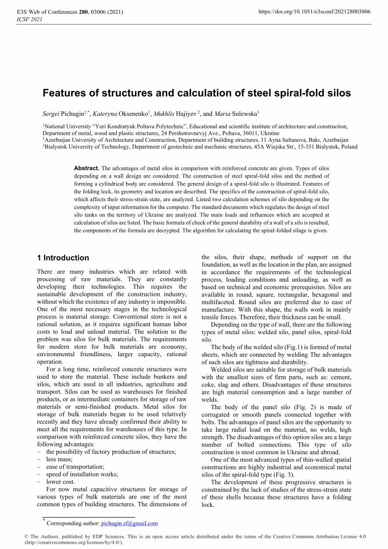
Features of structures and calculation of steel spiral-fold silos
Sergei Pichugin1,*, Kateryna Oksenenko1, Mukhlis Hajiyev 2, and Maria Sulewska3
1National University “Yuri Kondratyuk Poltava Polytechnic”, Educational and scientific institute of architecture and construction, Department of metal, wood and plastic structures, 24 Pershotravnevyj Ave., Poltava, 36011, Ukraine 2Azerbaijan University of Architecture and Construction, Department of building structures, 11 Ayna Sultanova, Bakı, Azerbaijan 3Bialystok University of Technology, Department of geotechnic and mechanic structures, 45A Wiejska Str., 15-351 Bialystok, Poland
Abstract. The advantages of metal silos in comparison with reinforced concrete are given. Types of silos depending on a wall design are considered. The construction of steel spiral-fold silos and the method of forming a cylindrical body are considered. The general design of a spiral-fold silo is illustrated. Features of the folding lock, its geometry and location are described. The specifics of the construction of spiral-fold silo, which affects their stress-strain state, are analyzed. Listed two calculation schemes of silо depending on the complexity of input information for the computer. The standard documents which regulates the design of steel silo tanks on the territory of Ukraine are analyzed. The main loads and influences which are accepted at calculation of silos are listed. The basic formula of check of the general durability of a wall of a silo is resulted, the components of the formula are decrypted. The algorithm for calculating the spiral-folded silage is given.
1 Introduction There are many industries which are related with processing of raw materials. They are constantly developing their technologies. This requires the sustainable development of the construction industry, without which the existence of any industry is impossible. One of the most necessary stages in the technological process is material storage. Conventional store is not a rational solution, as it requires significant human labor costs to load and unload material. The solution to the problem was silos for bulk materials. The requirements for modern store for bulk materials are economy, environmental friendliness, larger capacity, rational operation.
For a long time, reinforced concrete structures were used to store the material. These include bunkers and silos, which are used in all industries, agriculture and transport. Silos can be used as warehouses for finished products, or as intermediate containers for storage of raw materials or semi-finished products. Metal silos for storage of bulk materials began to be used relatively recently and they have already confirmed their ability to meet all the requirements for warehouses of this type. In comparison with reinforced concrete silos, they have the following advantages: – the possibility of factory production of structures; – less mass; – ease of transportation; – speed of installation works; – lower cost.
For now metal capacitive structures for storage of various types of bulk materials are one of the most common types of building structures. The dimensions of
the silos, their shape, methods of support on the foundation, as well as the location in the plan, are assigned in accordance the requirements of the technological process, loading conditions and unloading, as well as based on technical and economic prerequisites. Silos are available in round, square, rectangular, hexagonal and multifaceted. Round silos are preferred due to ease of manufacture. With this shape, the walls work in mainly tensile forces. Therefore, their thickness can be small.
Depending on the type of wall, there are the following types of metal silos: welded silo, panel silos, spiral-fold silo.
The body of the welded silo (Fig.1) is formed of metal sheets, which are connected by welding The advantages of such silos are tightness and durability.
Welded silos are suitable for storage of bulk materials with the smallest sizes of firm parts, such as: cement, coke, slag and others. Disadvantages of these structures are high material consumption and a large number of welds.
The body of the panel silo (Fig. 2) is made of corrugated or smooth panels connected together with bolts. The advantages of panel silos are the opportunity to take large radial load on the material, no welds, high strength. The disadvantages of this option silos are a large number of bolted connections. This type of silo construction is most common in Ukraine and abroad.
One of the most advanced types of thin-walled spatial constructions are highly industrial and economical metal silos of the spiral-fold type (Fig. 3).
The development of these progressive structures is constrained by the lack of studies of the stress-strain state of these shells because these structures have a folding lock.
ICSF 2021E3S Web of Conferences 280, 03006 (2021) https://doi.org/10.1051/e3sconf/202128003006
© The Authors, published by EDP Sciences. This is an open access article distributed under the terms of the Creative Commons Attribution License 4.0 (http://creativecommons.org/licenses/by/4.0/).

Fig. 1. Welded silo [1].
Fig. 2. Panel silo [2].
Fig. 3. Spiral-fold silo.
A number of domestic and foreign scientists have been engaged in the analysis of structures, calculation methods and experimental studies of cylindrical shells of metal
silos for strength and stability [3-17]. Mileykovsky et al. [5] in their work presented a computational model of the shell in the form of a scan of a cylindrical surface, which is considered as a ribbed plate with inclined edges. To simplify the calculation, the folding ribs are placed horizontally. The solution of the problem is reduced to the calculation of a cylindrical shell with annular ribs for axisymmetric loading. Trofimov et al. [6] in their work presented the results of an experimental study on full-scale spiral-fold silos.
Studies conducted by the authors showed that the horizontal pressure around the perimeter of the tank can be taken as a uniform, and in height – according to the Jansen’s formula with a coefficient of friction – 0,3. It was also found that the initial imperfection of the silo wall between the folding locks has the shape of a sinusoid, which is located symmetrically about the axis of the folding rib. Based on the obtained results, the authors concluded that the leakage of bulk material (grain) is uniform, and additional (ring or local) horizontal pressure can be ignored. Goldenberg [7] describes the experiment of stability of a closed cylindrical shell of a filled silo with often placed horizontal ribs of the folding type. The axisymmetric form of loss of stability of an isotropic shell is accepted. The most unfavorable combination of operating loadings which consider real conditions of deformation of a silo is considered: initial curvature of the wall and its compatible work with the elastic filler. In Heisen’s work [8] was investigated the influence of initial imperfections of the surface of the silo shell on the local stability and strength of the wall in the stage of elastic deformation. Nascimento [9] in his work conducted a research of the horizontal pressure in a metal silo with a corrugated wall, and compared the obtained theoretical data, according to different standards. Coelho [10] presented software for calculating the pressure in cylindrical containers with different types of bulk material.
However, the development of spiral-fold silos is constrained by the lack of studies of the stress-strain state of these shells, as these structures have a number of specific design features. There are also no developments regarding the reliability of these silos, though the basic principles of calculation of reliability of metal constructions are developed [16].
The task of this article is to review the design features and analysis of the method of calculation of metal spiral-fold silos and the algorithm of their calculation.
2 Basic material and results
The construction of the spiral-fold silo was developed in 1968 by a German scientist Xavier Lipp, who used the special equipment for processing of sheet metal and used it for the construction of silos spiral-fold [18]. The first silo was built in 1969 in Germany (Fig. 4).
Since the late 60’s in Europe they began using the silos with this type of construction. Within ten years of study and research, in practice, this technology has proved
ICSF 2021E3S Web of Conferences 280, 03006 (2021) https://doi.org/10.1051/e3sconf/202128003006
2

successful, and since the early 70's large-scale production of galvanized steel spiral-fold silos has begun.
Fig. 4. The first spiral-fold silo of Xaver Lipp, 1969, [18].
Process of assembling the silo structure is very simple. Steel coils, machines and accessories are transported to the building site where the silo is then constructed – the process is fast, efficient and flexible in terms of silo height and diameter. Unique technology allows for compact and fast installation of high-strength and hermetical silos directly at the construction site, without the use of bolts and welded joints (Fig. 5)
First step of construction (Fig.5, a) is two machines, steel coils and a profile ring are set up on the foundation slab. Once the profile ring and the two machines are in position and have been set up, the construction of the silo starts. The first machine (profiling machine) feeds the steel strip at a slight angle to form a profile. Once the steel strip has completed a revolution, the adjacent profiled strips are brought together in the second machine. They are then folded together tightly. The method of construction is comparable with a screw that moves forward with each revolution as the silo takes shape. The two machines remain in position feeding the steel strip while the silo is formed, growing higher in a spiral.
Second step of construction (Fig.5, b) starts when the silo has reached a height of approximately 2 metres, the top edge is cut level. The roof is then installed or further connectors and parts are fitted or openings are made.
When the roof is installed then starts third step of construction (Fig.5, c). The silo will continue to be formed slowly until it reaches its predetermined height. Ladders and supports will be added during the construction process.
As soon as the desired height has been reached, the bottom edge is cut level and the components are removed from inside the silo. The silo is set down on the foundation slab by reversing the direction of revolution and is then fixed in position, marking the completion of the construction process.
The construction of the spiral-fold cylindrical silo is formed with the help of special equipment, which connects a metal strip (495 mm wide and 2-4 mm thick) in a spiral with the simultaneous formation of the folding lock. The folding lock is located outside the silo wall at a slight angle to the horizontal plane and forms annular ribs. Folding ribs have a height of l0, consist of the upper and
lower halves. They have different geometry, rigidity and pliability. The step of the ring ribs is 365 mm (Fig. 6).
a) first step
b) second step
c) third step
Fig. 5. Process of assembling the silo structure [19].
Spiral-fold silo shell designs are significantly different from traditional corrugated metal prefabricated silos with bolted joints.
ICSF 2021E3S Web of Conferences 280, 03006 (2021) https://doi.org/10.1051/e3sconf/202128003006
3

Fig. 6. Construction of a spiral-fold silo.
The specifics of the design of the spiral-fold silo,
which affects to their stress-strain state, is as follows: The ribs are placed in a spiral, but at a slight angle
of inclination of the folding lock, close to 1⁰. These folding ribs work in a complex stress state.
They not only increase the rigidity of the silo shell structure in tension and bending in the annular direction, but at the same time reduce the stiffness of the structure, in the transition of the wall to the folding lock. Longitudinal forces generated in the wall of the cylindrical shell, at the location of the ribs, are transmitted from top to bottom with eccentricity, which leads to additional deformation, both in the wall of the shell and between the layers of the rib.
Depending on whether the silo shell is extended or compressed along the forming line, the stiffness and pliability of the folding lock will be different. In some cases of external influences, such as wind load, requires consideration of the shell as a structural nonlinear system.
Quite frequent placement of the ribs and the small angle of their inclination allow us to consider it as a system of closely spaced horizontal ribs, and the stress state of the filled silo as axisymmetric.
3 Analysis of normative documents of Ukraine on the calculation of metal spiral-fold silos The main normative document in Ukraine that regulates the design of metal structures, including thin-walled shells is DBN B.2.6-198: 2014 [20]. This document contains general recommendations for assessing the strength and stability of torsion shells.
Another normative document in Ukraine that regulates the design of steel silo tanks, classification of their structures, determination of loads and forces in the elements is DBN B.2.2-8-98. [21], which was issued to replace SNiP 2.10.05-85 [22]. Additionally, some requirements are given in SNiP 2.09.03-85. [23].
The calculation of spiral-fold silos is considered in detail in [24]. In [24] the calculation scheme is accepted, which in the case of a filled silo, can be solved for all the loads specified in the DBN B.2.2-8-98. [21], both in a simpler and in a more precise formulation.
а)
b) Fig. 7. Calculated schemes of silo a) Simplified; b) Precised.
Simplified calculation scheme (Fig. 7, a) (in the sense of entering the source information for the computer) is reduced to the calculation of a single shell under the
ICSF 2021E3S Web of Conferences 280, 03006 (2021) https://doi.org/10.1051/e3sconf/202128003006
4
assumption that the height of the same thickness, the calculated horizontal load and total vertical pressure are constant and equal to their maximum value. For the lower zone, the maximum values are taken at the level of the upper lower shell.
A more precise calculation scheme (Fig. 7, b) is reduced to the calculation of the entire silo as a cylindrical shell with frequent discrete placement of annular ribs. The calculation is performed on the action of horizontal and vertical load. In each shell, these loads are assumed to be constant and equal. The horizontal load corresponds to the maximum value of the design load at the bottom of each shell. The longitudinal force from the vertical load corresponds to the maximum value of force in this shell, which is applied to its lower edge.
As a calculation scheme of the whole silo, a component system of short shells connected by horizontal folding ribs is accepted (Fig. 6). The height of the short components of the shell is equal to 10. The height of folding lock is equal to l0. It consists of the upper and lower halves, which differ in their geometry, rigidity and pliability.
The main loads and effects on the silo are: horizontal and vertical (due to friction) loads from
the pressure of bulk materials, taking into account the central unloading of the silo;
own weight of a construction; loads from snow on a covering; temperature fluctuation; loads from heat cables; loads from wind pressure (for unfilled silo).
These loads are temporary (long-term, and short-term), except for its own weight.
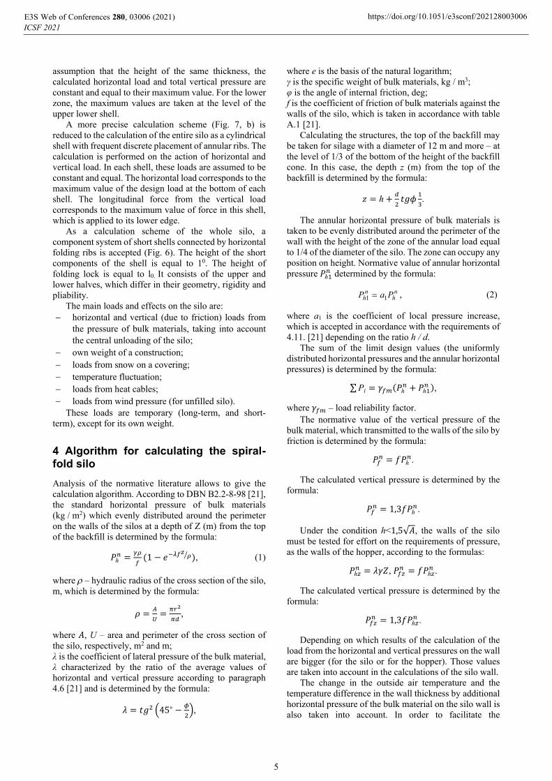
4 Algorithm for calculating the spiral-fold silo Analysis of the normative literature allows to give the calculation algorithm. According to DBN B2.2-8-98 [21], the standard horizontal pressure of bulk materials (kg / m2) which evenly distributed around the perimeter on the walls of the silos at a depth of Z (m) from the top of the backfill is determined by the formula:
푃ℎ = (1 − 푒 ), (1)
where – hydraulic radius of the cross section of the silo, m, which is determined by the formula:
휌 = = ,
where 훢, U – area and perimeter of the cross section of the silo, respectively, m2 and m; λ is the coefficient of lateral pressure of the bulk material, λ characterized by the ratio of the average values of horizontal and vertical pressure according to paragraph 4.6 [21] and is determined by the formula:
휆 = 푡푔 45∘ − ,
where e is the basis of the natural logarithm; γ is the specific weight of bulk materials, kg / m3; φ is the angle of internal friction, deg; f is the coefficient of friction of bulk materials against the walls of the silo, which is taken in accordance with table A.1 [21].
Calculating the structures, the top of the backfill may be taken for silage with a diameter of 12 m and more – at the level of 1/3 of the bottom of the height of the backfill cone. In this case, the depth z (m) from the top of the backfill is determined by the formula:
푧 = ℎ+ 푡푔휙 .
The annular horizontal pressure of bulk materials is taken to be evenly distributed around the perimeter of the wall with the height of the zone of the annular load equal to 1/4 of the diameter of the silo. The zone can occupy any position on height. Normative value of annular horizontal pressure 푃ℎ determined by the formula:
nh
nh PaP 11 , (2)
where a1 is the coefficient of local pressure increase, which is accepted in accordance with the requirements of 4.11. [21] depending on the ratio h / d.
The sum of the limit design values (the uniformly distributed horizontal pressures and the annular horizontal pressures) is determined by the formula:
∑Рі = 훾 (푃ℎ + 푃ℎ ),
where 훾 – load reliability factor. The normative value of the vertical pressure of the
bulk material, which transmitted to the walls of the silo by friction is determined by the formula:
푃 = 푓푃ℎ .
The calculated vertical pressure is determined by the formula:
푃 = 1,3푓푃ℎ .
Under the condition h˂1,5√퐴, the walls of the silo must be tested for effort on the requirements of pressure, as the walls of the hopper, according to the formulas:
푃ℎ = 휆훾푍, 푃 = 푓푃ℎ .
The calculated vertical pressure is determined by the formula:
푃 = 1,3푓푃ℎ .
Depending on which results of the calculation of the load from the horizontal and vertical pressures on the wall are bigger (for the silo or for the hopper). Those values are taken into account in the calculations of the silo wall.
The change in the outside air temperature and the temperature difference in the wall thickness by additional horizontal pressure of the bulk material on the silo wall is also taken into account. In order to facilitate the
ICSF 2021E3S Web of Conferences 280, 03006 (2021) https://doi.org/10.1051/e3sconf/202128003006
5
calculations, the pressure is taken evenly distributed around the perimeter and height.
The normative value of this pressure 푃ℎ , MPa (kg/cm2), is determined by the formula:
푃ℎ =( )
, (3)
where 푇 is the average daily amplitude of fluctuations in ambient air temperature (deg), which is accepted 2휃 , where 휃 is determined according to DBN B.1.2–2: 2006 [25]; 퐸 – the deformation modulus of compression of the bulk material is determined by the formula:
퐸 = 250 ⋅ (푃ℎ ) , ,
cE – modulus of elasticity of the material of the silo walls; 푘 – coefficient, which for steel walls is equal to 2.5; 훼 – coefficient of linear temperature deformation of the wall material, 1 / deg; d is the inner diameter of the silo, m; t – wall thickness, m; v is the initial coefficient of transverse deformations (Poisson's ratio).
The maximum design load from the additional horizontal pressure of the grain on the wall of the silo, taking into account the temperature difference is determined by the formula:
푃ℎ = 훾 푃ℎ ,
훾 – load reliability factor. The maximum calculated snow evenly distributed
load is calculated in accordance with current building codes.
The maximum calculated wind is evenly distributed along the perimeter of the silo wall, depending on the type of terrain.
Checks of the total strength of the wall, which is in a momentless stress state, according to 14.1 [20] are performed by the formula:
휎 − 휎 휎 + 휎 + 3휏 ≤ 1, (4)
where 휎х and 휎у – normal stresses in two mutually perpendicular directions; 휏ху – tangential stresses at the point of the wall of the shell under consideration; 훾с – coefficient of working conditions of the structure.
The strongest stress of a shell depending on wall thickness is checked for durability.
5 Conclusions 1. The advantages of metal silos in comparison with
reinforced concrete are given. 2. Types of silos depending on a wall design are
considered. 3. The design of steel spiral-fold silo is illustrated.
4. The specifics of the construction of spiral-fold silo, which affects their stress-strain state, are analyzed.
5. The normative documents of Ukraine regulating the issues of designing steel silo tanks are analyzed.
6. The algorithm for calculating steel spiral-fold silo is resulted: from load collection to strength testing.
Based on the above material, the authors are planning to conduct an experiment on a full-scale silo to compare theoretical calculations with the experiment results.
References 1. Welded silo. https://hap.com.ua/uk/services. 2. Panel silo.
https://www.pinterest.com/pin/351912449176941/. 3. E.I. Lessig, A.F. Lileev, A.G Sokolov, Sheet metal
structures (Stroyizdat, Moscow, 1970) 4. I.Ya. Amiro, V.A. Zarutskyy, P.S. Polyakov, Ribbed
cylindrical shells (Naukova dumka, Kiev, 1973) 5. I.E. Mileykovskiy, Н.Н. Stolypin, B.N Skotnikov,
G.I Solovyov, Construction mechanics and calculation of structures 5, 19-23 (1985)
6. V.M. Trofimov, B.E Kiselev, L.B Katznelson, Construction mechanics and calculation of structures 6, 66-70 (1985).
7. L.I. Goldenberg, Construction mechanics and calculation of structures 1, 60-64 (1985)
8. R.E. Geisen, Construction mechanics and calculation of structures 2, 34-37 (1986)
9. J.W.B Do Nascimento, J.P. Lopes Neto, M.D. Montross, Eng. Agríc. 33(4), 601-611 (2013)
10. L.C. Coelho, C. Calil Júnior, Journal of Advances in Information Technology 8, 47-51 (2017)
11. P. Wang, L. Zhu, X. Zhu, Powder Technology 295, 104-114 (2016)
12. S. Widisinghe, N. Sivakugan, in Ground Engineering in a Changing World, 11th Australia – New Zealand Conference on Geomechanics (2012)
13. A. Couto, A Ruiz, L. Herráez, J. Moran, P.J. Aguado, Computers and Electronics in Agriculture 96, 40-56 (2013). doi:10.1016/j.compag.2013.04.011
14. J. Marcinowski. Heliyon 5, 47-51 (2019) 15. M.Z. Fank, J.W.B Do Nascimento, D.L. Cardoso,
A.S. Meira, F.L. Willrich, Engenharia Agrícola 38, 498-503 (2018) doi:10.1590/1809-4430-Eng.Agric.v38n4p498-503/2018
16. S.F Pichugin, Magazine of Civil Engineering 83(7), 24-37 (2014). doi:10.18720/MCE.83.3
17. S. Pichugin, K. Oksenenko, Academic journal. Series: Industrial Machine Building, Civil Engineering 53(2), 54-60 (2019). doi:10.26906/znp.2019.53.1890
18. Хaver Lipp. https://xaver-lipp.com/ 19. Process of assembling the silo structure.
https://www.lipp-system.de/lipp-system/lipp-double-seam/?lang=en.
ICSF 2021E3S Web of Conferences 280, 03006 (2021) https://doi.org/10.1051/e3sconf/202128003006
6

20. DBN B.2.6-198: 2014 Steel structures. Design standards (Ministry of Regional Development of Ukraine, Kyiv, 2014)
21. DBN B.2.2-8-98 Enterprises, buildings and structures for storage and processing of grain (State Construction Committee of Ukraine, Kyiv, 1998)
22. SNiP 2.10.05-85 Enterprises, buildings and structures for storage and processing of grain (CITP Gosstroy USSR, Moscow, 1985)
23. SNiP 2.09.03-85 Constructions of industrial enterprises (CITP Gosstroya SSSR, Moscow, 1986)
24. Manual for the design of enterprises, buildings and structures for storage and processing of grain: a manual for SNiP 2.10.05-85 (CITP Gosstroya SSSR, Moscow, 1989).
25. DBN B.1.2-2: 2006 Loads and effects. Design standards (Ministry of Construction of Ukraine, Kyiv, 2006).
ICSF 2021E3S Web of Conferences 280, 03006 (2021) https://doi.org/10.1051/e3sconf/202128003006
7