Embed Size (px)
Citation preview
Time-R
esolved
Features and Benefits • USB2.0connection Simple Plug & Play connection
• Multi-MHzReadoutspeeds Rapid image capture for fast transition phenomena analysis
•IntegratedDigitalDelayGenerator With comprehensive software controls
• Close-CoupledGating < 2 ns true optical gating speeds - ultimate temporal resolution
• Lowestinsertiondelay As low as 19 ns
• Fibre-opticcoupling High optical throughput without vignetting
• IntelliGate™ MCP gating for On/Off ratios >108 in the UV
• Photocathodegatingrateupto500kHz Increased Signal to Noise ratio for high speed laser-based experiments
•Croppedsensormode Specialised acquisition mode to achieve fastest image acquisition rate
•HighresolutionGen2and3intensifiers Highest available intensifier resolution with QE > 50% and sensitivity options from 120 nm to 1,100 nm
•Thermo-Electriccoolingdownto-40°C Ideal for low-light applications
•Real-timecontrol Intuitive Windows user interface for real-time acquisition optimization
•Photocathodedrygaspurgeport Provides further EBI reduction for low-light applications
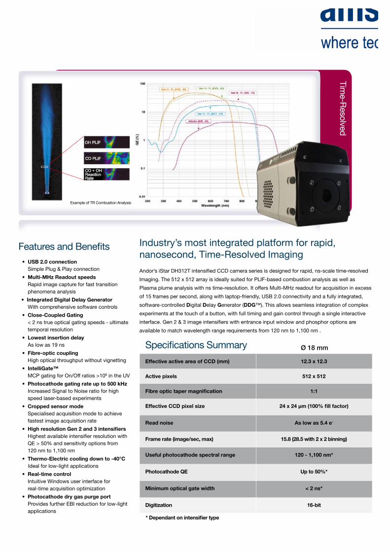
OH PLIF
CO PLIF
CO + OHReactionRate
22 mm
Example of TR Combustion Analysis
Industry’s most integrated platform for rapid, nanosecond, Time-Resolved Imaging
Andor’s iStar DH312T intensified CCD camera series is designed for rapid, ns-scale time-resolved
Imaging. The 512 x 512 array is ideally suited for PLIF-based combustion analysis as well as
Plasma plume analysis with ns time-resolution. It offers Multi-MHz readout for acquisition in excess
of 15 frames per second, along with laptop-friendly, USB 2.0 connectivity and a fully integrated,
software-controlled Digital Delay Generator (DDG™). This allows seamless integration of complex
experiments at the touch of a button, with full timing and gain control through a single interactive
interface. Gen 2 & 3 image intensifiers with entrance input window and phosphor options are
available to match wavelength range requirements from 120 nm to 1,100 nm .
Specifications Summary
EffectiveactiveareaofCCD(mm) 12.3x12.3
Activepixels 512x512
Fibreoptictapermagnification 1:1
EffectiveCCDpixelsize 24x24µm(100%fillfactor)
Readnoise Aslowas5.4e-
Framerate(image/sec,max) 15.8(28.5with2x2binning)
Usefulphotocathodespectralrange 120-1,100nm*
PhotocathodeQE Upto50%*
Minimumopticalgatewidth <2ns*
Digitization 16-bit
Ø 18 mm
*Dependantonintensifiertype
Specifications - Gen 2 Image Intensifiers •1
Photocathodemodel 18*-03 18*-04 18*-05† 18H-13 18H-83 18*-E3
Usefulaperture Ø18 mm
Inputwindow Quartz Quartz MgF2 Quartz Quartz Quartz
Photocathodetype W-AGT W-AGT W-AGT WR UW WE-AGT
PeakQE@roomtemperature•2 18 18 15 13.5 25 22
Wavelengthrange 180 - 850 nm 180 - 850 nm 120 - 850 nm 180 - 920 nm 180 - 850 nm 180 - 850 nm
Imageintensifierresolutionlimit•3 25 µm 30 µm 25 µm 25 µm 25 µm 25 µm
Phosphortype[decaytimeto10%] P43 [2 ms] P46 [200 ns] P43 [2 ms] P43 [2 ms] P43 [2 ms] P43 [2 ms]
Minimumopticalgatewidth(ns)•4,5
U(Ultrafast)F(Fast)
H(HighQE)
< 2< 5-
< 2< 5-
< 5< 10
-
--
< 50
--
< 100
< 2< 5-
Maximumrelativegain•6 > 1000 > 500 > 1000 > 850 > 500 > 300
Maximumphotocathoderepetitionrate(withIntelligate™OFF)
500 kHz (continuous)
Maximumphotocathoderepetitionrate(withIntelligate™ON)
5 kHz (continuous)
EquivalentBackgroundIlluminance(EBI) < 0.2 e-/pix/sec
* Substitute with appropriate gate width option, e.g. 18F-03 (please refer to page 5 for detailed ordering information)† Available with VUV-compatible spectrograph interface
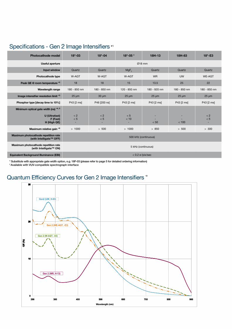
Quantum Efficiency Curves for Gen 2 Image Intensifiers •2
3030
Gen2 (UW, H-83)
30
Gen2 (UW, H-83)
20
30
Gen2 (UW, H-83)
Gen 2 (WE-AGT, -E3)20
30
Gen2 (UW, H-83)
Gen 2 (W-AGT, -03)
Gen 2 (WE-AGT, -E3)20
30
Gen2 (UW, H-83)
Gen 2 (W-AGT, -03)
Gen 2 (WE-AGT, -E3)
QE
(%)
10
20
30
Gen2 (UW, H-83)
Gen 2 (W-AGT, -03)
Gen 2 (WE-AGT, -E3)
QE
(%)
10
20
30
Gen2 (UW, H-83)
Gen 2 (W-AGT, -03)
Gen 2 (WE-AGT, -E3)
QE
(%)
10
20
30
Gen2 (UW, H-83)
Gen 2 (W-AGT, -03)
Gen 2 (WR, H-13)
Gen 2 (WE-AGT, -E3)
QE
(%)
10
20
30
Gen2 (UW, H-83)
Gen 2 (W-AGT, -03)
Gen 2 (WR, H-13)
Gen 2 (WE-AGT, -E3)
QE
(%)
0
10
20
30
200 300 400 500 600 700 800 900
Wavelength (nm)
Gen2 (UW, H-83)
Gen 2 (W-AGT, -03)
Gen 2 (WR, H-13)
Gen 2 (WE-AGT, -E3)
QE
(%)
0
10
20
30
200 300 400 500 600 700 800 900
Wavelength (nm)
Gen2 (UW, H-83)
Gen 2 (W-AGT, -03)
Gen 2 (WR, H-13)
Gen 2 (WE-AGT, -E3)
QE
(%)
Specifications - Gen 3 Image Intensifiers •1
Photocathodemodel 18*-63 18*-73 18*-93 18*-A3 18*-C3
Usefulaperture Ø 18 mm
Inputwindow Glass Glass Glass GlassMgF2 + F/O +
Lumogen
Photocathodetype HVS VIH NIR EVS BGT
PeakQE@roomtemperature•2 > 47.5 > 25.5 4 > 40 > 17
Wavelengthrange 280 - 760 nm 280 - 910 nm 380 - 1090 nm 280 - 810 nm < 200 - 910 nm
Imageintensifierresolutionlimit•3 30 µm 30 µm 30 µm 30 µm 40 µm
Phosphortype[decaytimeto10%] P43 [2 ms]
Minimumopticalgatewidth(ns)•5
U(Ultrafast)F(Fast)
< 2< 5
Maximumrelativegain•6 > 200
Maximumphotocathoderepetitionrate(withIntelligate™OFF)
500 kHz (continuous)
Maximumphotocathoderepetitionrate(withIntelligate™ON)
5 kHz (continuous)
EquivalentBackgroundIlluminance(EBI) < 0.1 e-/pix/sec < 0.3 e-/pix/sec < 2 e-/pix/sec < 0.2 e-/pix/sec < 0.3 e-/pix/sec
* Substitute with appropriate gate width option, e.g. 18U-63 (please refer to page 5 for detailed ordering information)
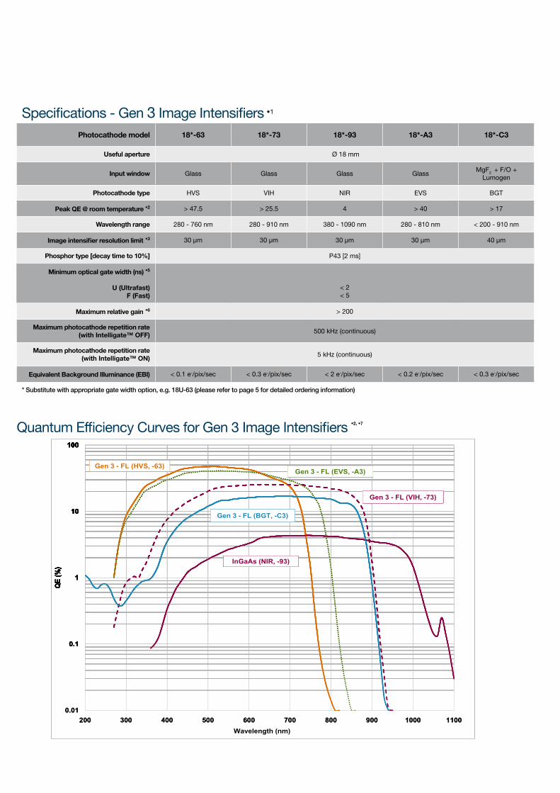
Quantum Efficiency Curves for Gen 3 Image Intensifiers •2,•7
100
Gen 3 - FL (HVS, -63)Gen 3 - FL (EVS, -A3)
100
Gen 3 - FL (HVS, -63)
Gen 3 - FL (VIH, -73)
Gen 3 - FL (EVS, -A3)
10
100
Gen 3 - FL (HVS, -63)
Gen 3 - FL (VIH, -73)
Gen 3 - FL (BGT, -C3)
Gen 3 - FL (EVS, -A3)
10
100
%)
Gen 3 - FL (HVS, -63)
Gen 3 - FL (VIH, -73)
Gen 3 - FL (BGT, -C3)
InGaAs (NIR, -93)
Gen 3 - FL (EVS, -A3)
1
10
100
QE
(%)
Gen 3 - FL (HVS, -63)
Gen 3 - FL (VIH, -73)
Gen 3 - FL (BGT, -C3)
InGaAs (NIR, -93)
Gen 3 - FL (EVS, -A3)
1
10
100
QE
(%)
Gen 3 - FL (HVS, -63)
Gen 3 - FL (VIH, -73)
Gen 3 - FL (BGT, -C3)
InGaAs (NIR, -93)
Gen 3 - FL (EVS, -A3)
0.1
1
10
100
QE
(%)
Gen 3 - FL (HVS, -63)
Gen 3 - FL (VIH, -73)
Gen 3 - FL (BGT, -C3)
InGaAs (NIR, -93)
Gen 3 - FL (EVS, -A3)
0.1
1
10
100
QE
(%)
Gen 3 - FL (HVS, -63)
Gen 3 - FL (VIH, -73)
Gen 3 - FL (BGT, -C3)
InGaAs (NIR, -93)
Gen 3 - FL (EVS, -A3)
0.01
0.1
1
10
100
200 300 400 500 600 700 800 900 1000 1100
QE
(%)
Gen 3 - FL (HVS, -63)
Gen 3 - FL (VIH, -73)
Gen 3 - FL (BGT, -C3)
InGaAs (NIR, -93)
Gen 3 - FL (EVS, -A3)
0.01
0.1
1
10
100
200 300 400 500 600 700 800 900 1000 1100Wavelength (nm)
QE
(%)
Gen 3 - FL (HVS, -63)
Gen 3 - FL (VIH, -73)
Gen 3 - FL (BGT, -C3)
InGaAs (NIR, -93)
Gen 3 - FL (EVS, -A3)
Have you found what you are looking for?Need higher resolution? The DH334T series cameras offers 13.5 x 13.5 µm pixels for higher resolution imaging & spectroscopy.Need faster response phosphor for Fast Kinetics? P46 phosphor is available as an option for all intensifier models.Need wider sensor format? The DH320T & high resolution DH340T series offer up to 25 mm field of view when combined with Ø 25 mm image intensifier options.Need a customized version? Please contact us to discuss our Customer Special Request options (CSR).
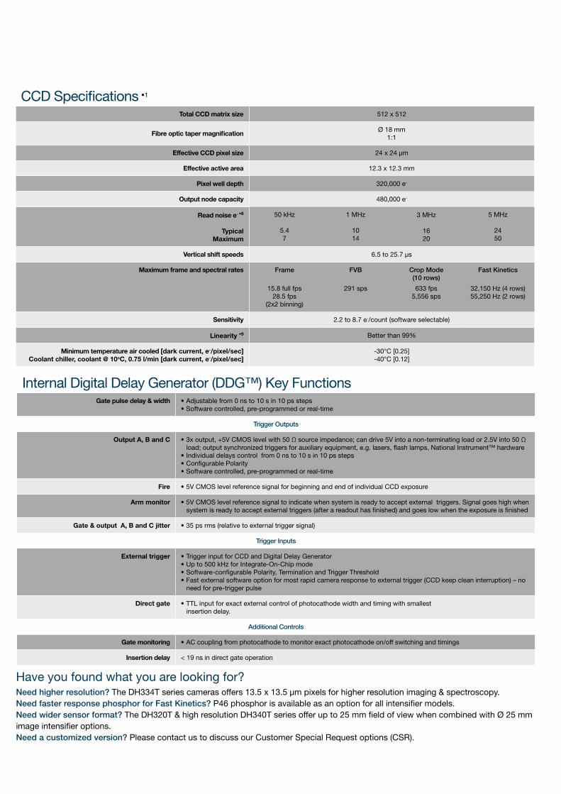
CCD Specifications •1
TotalCCDmatrixsize 512 x 512
FibreoptictapermagnificationØ 18 mm
1:1
EffectiveCCDpixelsize 24 x 24 µm
Effectiveactivearea 12.3 x 12.3 mm
Pixelwelldepth 320,000 e-
Outputnodecapacity 480,000 e-
Readnoisee-•8
TypicalMaximum
50 kHz
5.47
1 MHz
1014
3 MHz
1620
5 MHz
2450
Verticalshiftspeeds 6.5 to 25.7 µs
Maximumframeandspectralrates Frame
15.8 full fps28.5 fps
(2x2 binning)
FVB
291 sps
Crop Mode (10 rows)
633 fps 5,556 sps
Fast Kinetics
32,150 Hz (4 rows)55,250 Hz (2 rows)
Sensitivity 2.2 to 8.7 e-/count (software selectable)
Linearity•9 Better than 99%
Minimumtemperatureaircooled[darkcurrent,e-/pixel/sec]Coolantchiller,coolant@10oC,0.75l/min[darkcurrent,e-/pixel/sec]
-30°C [0.25]-40°C [0.12]
Internal Digital Delay Generator (DDG™) Key FunctionsGatepulsedelay&width • Adjustable from 0 ns to 10 s in 10 ps steps
• Software controlled, pre-programmed or real-time
Trigger Outputs
OutputA,BandC • 3x output, +5V CMOS level with 50 Ω source impedance; can drive 5V into a non-terminating load or 2.5V into 50 Ω load; output synchronized triggers for auxiliary equipment, e.g. lasers, flash lamps, National Instrument™ hardware• Individual delays control from 0 ns to 10 s in 10 ps steps• Configurable Polarity• Software controlled, pre-programmed or real-time
Fire • 5V CMOS level reference signal for beginning and end of individual CCD exposure
Armmonitor • 5V CMOS level reference signal to indicate when system is ready to accept external triggers. Signal goes high when system is ready to accept external triggers (after a readout has finished) and goes low when the exposure is finished
Gate&outputA,BandCjitter • 35 ps rms (relative to external trigger signal)
Trigger Inputs
Externaltrigger • Trigger input for CCD and Digital Delay Generator• Up to 500 kHz for Integrate-On-Chip mode• Software-configurable Polarity, Termination and Trigger Threshold• Fast external software option for most rapid camera response to external trigger (CCD keep clean interruption) – no need for pre-trigger pulse
Directgate • TTL input for exact external control of photocathode width and timing with smallest insertion delay.
Additional Controls
Gatemonitoring • AC coupling from photocathode to monitor exact photocathode on/off switching and timings
Insertiondelay < 19 ns in direct gate operation
Step 4.
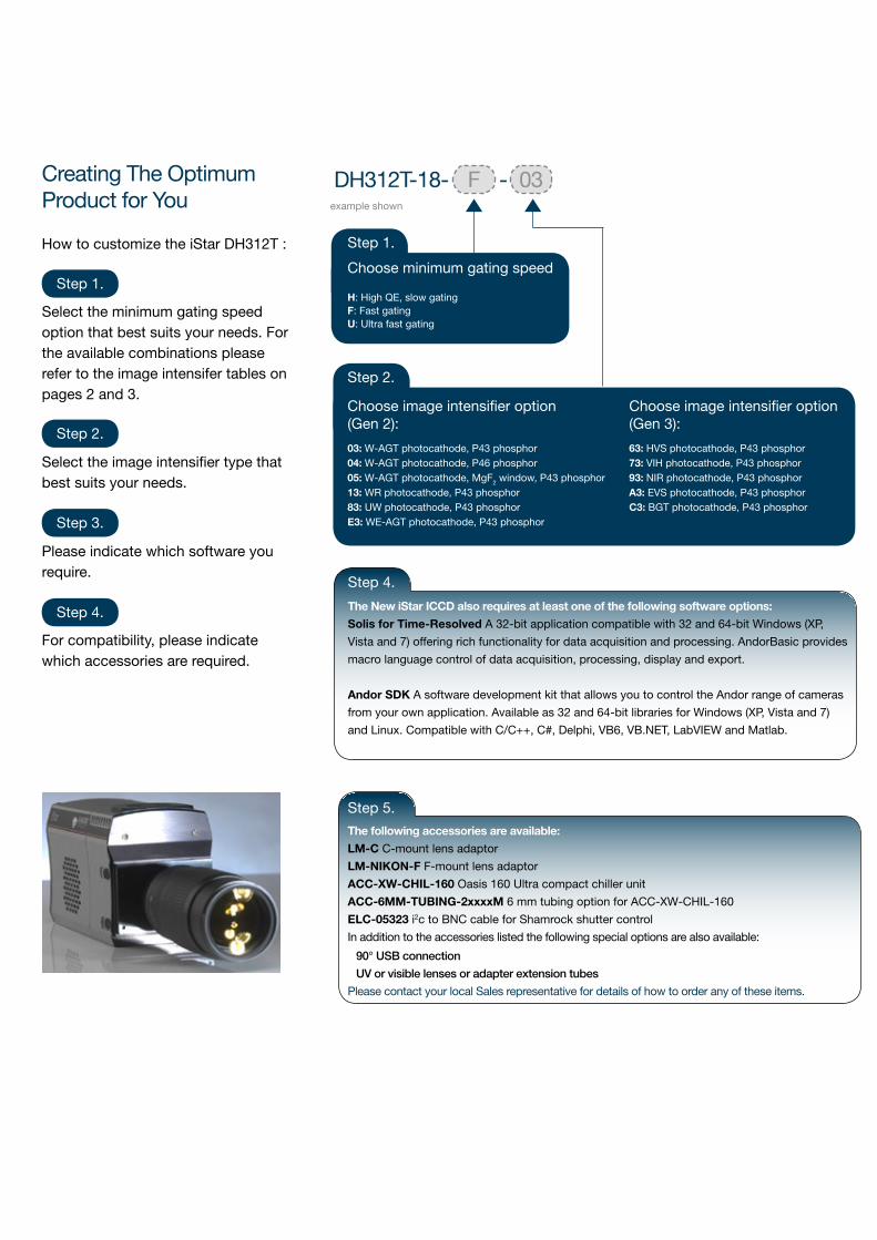
TheNewiStarICCDalsorequiresatleastoneofthefollowingsoftwareoptions:
SolisforTime-Resolved A 32-bit application compatible with 32 and 64-bit Windows (XP,
Vista and 7) offering rich functionality for data acquisition and processing. AndorBasic provides
macro language control of data acquisition, processing, display and export.
AndorSDK A software development kit that allows you to control the Andor range of cameras
from your own application. Available as 32 and 64-bit libraries for Windows (XP, Vista and 7)
and Linux. Compatible with C/C++, C#, Delphi, VB6, VB.NET, LabVIEW and Matlab.
Creating The Optimum Product for You
How to customize the iStar DH312T :
Select the minimum gating speed option that best suits your needs. For the available combinations please refer to the image intensifer tables on pages 2 and 3.
Step 1.
Please indicate which software you require.
Step 3.
F 03-
Step 1.
Choose minimum gating speedH: High QE, slow gatingF: Fast gatingU: Ultra fast gating
example shown
Step 2.
Select the image intensifier type that best suits your needs.
Step 2.
Step 4.
For compatibility, please indicate which accessories are required.
DH312T-18-
Step 2.
Step 2.
Choose image intensifier option (Gen 2):
03: W-AGT photocathode, P43 phosphor 04: W-AGT photocathode, P46 phosphor05: W-AGT photocathode, MgF2 window, P43 phosphor13: WR photocathode, P43 phosphor83: UW photocathode, P43 phosphorE3: WE-AGT photocathode, P43 phosphor
Choose image intensifier option(Gen 3):
63: HVS photocathode, P43 phosphor73: VIH photocathode, P43 phosphor93: NIR photocathode, P43 phosphorA3: EVS photocathode, P43 phosphorC3: BGT photocathode, P43 phosphor
Thefollowingaccessoriesareavailable:
LM-C C-mount lens adaptor
LM-NIKON-F F-mount lens adaptor
ACC-XW-CHIL-160 Oasis 160 Ultra compact chiller unit
ACC-6MM-TUBING-2xxxxM 6 mm tubing option for ACC-XW-CHIL-160
ELC-05323i2c to BNC cable for Shamrock shutter control
In addition to the accessories listed the following special options are also available:
90° USB connection
UV or visible lenses or adapter extension tubes
Please contact your local Sales representative for details of how to order any of these items.
Step 5.
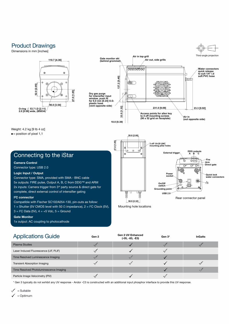
Applications Guide Gen2Gen2UVEnhanced
(-05,-83,-E3)Gen3* InGaAs
Plasma Studies
Laser Induced Fluorescence (LIF, PLIF)
Time Resolved Luminescence Imaging
Transient Absorption Imaging
Time Resolved Photoluminescence Imaging
Particle Image Velocimetry (PIV)
* Gen 3 typically do not exhibit any UV response - Andor -C3 is constructed with an additional input phosphor interface to provide this UV response.
Product DrawingsDimensions in mm [inches]
= Suitable
= Optimum
Weight: 4.2 kg [9 lb 4 oz]
= position of pixel 1,1n
137.
2 [5
.40]
33.
5 [1
.32]
23.3 [0.92] 231.0 [9.09]
10.0 [0.39]
Gate monitor skt(behind grommet) Air out, side grills
Water connectorsquick releaseto suit 1/4" i.dsoft PVC hose
Access points for allen keyto 4 off mounting screws(90 x 52 grid on faceplate) Air in
(out opposite side)
Dry gas purgefor intensifier inputwindow, push fit for 6.0 mm [0.24] O.D. plastic hose(vent opposite side)
Air in top grill
90.0 [3.54]
47.
0 [1
.85]
52.
0 [2
.05]
110.7 [4.36]
O-ring 53.7 I.D [2.11] 2.0 [0.08] wide, (BS034)
n
DDG outputs A B CExternal trigger
I C
USB 2.0
On/Offswitch
Powersocket
Grounding point
Direct gate
FireArm
Quick lockwater connectors
2
50.8 [2.00]
47.
0 [1
.85]
58.9 [2.32]
3 off 1/4-20 UNCmounting pillar holes
Rear connector panel
Mounting hole locations
Third-angle projection
Connecting to the iStarCameraControl
Connector type: USB 2.0
LogicInput/Output
Connector type: SMA, provided with SMA - BNC cable
5x outputs: FIRE pulse, Output A, B, C from DDG™ and ARM
2x inputs: Camera trigger from 3rd party source & direct gate for
complete, direct external control of intensifier gating
I2Cconnector
Compatible with Fischer SC102A054-130, pin-outs as follow:
1 = Shutter (5V CMOS level with 50 Ω impedance), 2 = I2C Clock (5V),
3 = I2C Data (5V), 4 = +5 Vdc, 5 = Ground
GateMonitor
1x output: AC coupling to photocathode

© A
MS
Tech
nolo
gies
. All
right
s re
serv
ed.
Germany
AMS Technologies AG
(Headquarters)
Fraunhoferstr. 22
82152 Martinsried
Germany
Phone +49 (0)89 895 77 0
Fax +49 (0)89 895 77 199
Italy
AMS Technologies S.r.l.
Via San Bernardino, 49
20025 Legnano (MI)
Italy
Phone +39 0331 596 693
Fax +39 0331 590 732
United Kingdom
AMS Technologies Ltd.
Unit 11, St Johns Business Park
Lutterworth
Leicestershire LE17 4HB
United Kingdom
Phone: +44 (0)1455 556360
Fax: +44 (0)1455 552974
Spain
AMS Technologies S.L.
C/Muntaner, 200 Atico, 4a
08036 Barcelona
Spain
Phone: +34 93 380 84 20
Fax: +34 93 380 84 21
France
AMS Technologies S.A.R.L.
1, avenue de l’Atlantique
Courtaboeuf
91976 Les Ulis - Courtaboeuf Cedex
France
Phone: +33 (0)1 64 86 46 00
Fax: +33 (0)1 69 07 87 19
Nordic
AMS Technologies Nordic
Azpect Photonics AB
Aminogatan 34
43153 Mölndal
Sweden
Phone +46 (0)8 55 44 24 80
Fax +46 (0)8 55 44 24 99
Optical Technologies
Power Technologies
Thermal Management www.amstechnologies.com
WHAT CAN WE DO FOR YOU?Please contact us for further information