Embed Size (px)
Citation preview

Feasibility Analysis of BIM Based Information System for Facility
Management at WPI
A Master Thesis
Submitted to the Faculty
Of the
Worcester Polytechnic Institute
In Partial fulfillment of the requirements for the
Degree of Masters of Science
In
Interdisciplinary Construction Project Management
By
_________
Zijia Liu
May 2010
Approved
Prof. Guillermo Salazar, PhD Signature
Prof. Leonard Albano, PhD Signature
Thesis Committee Members:
Alfredo DiMauro, Assistant VP for Facilities
Signature
Liz Tomaszewski, Facilities Systems Manager
Signature
Laura Handler; LEED AP; Tocci Building Corporation
Signature

I
Abstract
The traditional two-dimensional (2D) delivery system in construction industry creates
communication gaps among owners, architects, and contractors. These gaps exist in
all phases of project, but are more evident in operation and maintenance. Owners,
especially colleges, are now starting to explore and implement new methods to
receive more valuable as-built information.
Building Information Modeling (BIM) is an emerging information technology that
promotes a collaborative process for the Architectural, Engineering, Construction and
Facilities Management (AECFM) industry; it can facilitate the exchange and
interoperability of information management, and therefore could provide enhanced
benefits to colleges and universities’ physical plant.
The objective of this thesis is to determine the feasibility of using BIM concepts,
principles and tools to support and enhance the informational needs for planning,
design, procurement, construction, operation and maintenance of the physical plant of
WPI.
The methodologies used in this research include literature review of previous research
conducted by WPI students; case study analysis; interview with managers at
Department of Facilities, review other universities and owners’ experience with BIM,
and the review of material documented on the subject.
The thesis provides a conceptual guideline for implementation of BIM for WPI that

II
can be extended to other college campuses. The proposed guideline identifies the
scope of information that needs to be included in the model, establishes a process for
identify specific ways in which the information can be managed to meet the needs of
the facility management at WPI.
III
Acknowledgements
I would like to express the deepest appreciation to my academic advisor, Professor
Guillermo Salazar, who had always providing help, advice, and guidance throughout
my study at WPI.
I would like to thank my thesis committee members, Alfredo DiMauro, Liz
Tomaszewski, and Laura Handler. Without the collaboration of the committee, I
would not have so many great ideas in my thesis.
Thank Christopher Keegan, who had provided the model to my research. I definitely
learned a lot from him in Revit and other technical issues.
I owe special thanks to Michael Lane, David Messier, and Christopher Salter. The
interviews with them were quite successful; I collected enough information from them
to support my research.
Thank Hongwu Yang, who provided technical supports to develop the website.
To all my families, friends, thanks for being there, thank you for your support.

IV
Table of Contents
Abstract .......................................................................................................................... I
Acknowledgements ...................................................................................................... III
List of Figures: ............................................................................................................. VI
List of Tables: ........................................................................................................... VIII
1. Introduction ............................................................................................................. 1
2. Background ............................................................................................................. 5
2.1 BIM tools ......................................................................................................... 5
2.1.1Autodesk Revit............................................................................................... 5
2.2 BIM in industry and universities...................................................................... 9
2.2.1 The development of BIM in industry ............................................................ 9
2.2.2 BIM at WPI ................................................................................................. 14
2.2.3 BIM at other Universities............................................................................ 15
3. Methodology ......................................................................................................... 26
3.1 Literature Review........................................................................................... 26
3.2 Case Study ..................................................................................................... 26
3.3 Group Meeting and presentations .................................................................. 28
3.4 Previous BIM-Related Studies at WPI .......................................................... 29
3.5 Interviews ....................................................................................................... 31
4. Case Study ............................................................................................................ 32
4.1 The individual building section ..................................................................... 33
V
5. Conceptual BIM Execution Plan for WPI ............................................................ 49
5.1 Conceptual BIM plan for new buildings and renovations ............................. 50
5.2 Conceptual BIM plan for existing buildings and facilities ............................ 56
6. Conclusions & Recommendations ........................................................................... 63
Bibliography ................................................................................................................ 66
Appendix A - Interviews .............................................................................................. 69
Appendix B - IU BIM Proficiency Matrix ................................................................... 74
Appendix C- BIM Proficiency Matrix Submittal Firms (By 3/19/2010) .................... 75
Appendix D- Collaborative Process Mapping ............................................................. 76
Appendix E - BIM Execution Planning Process .......................................................... 78
Appendix F- Sample Room Schedule of Kaven Hall .................................................. 79

VI
List of Figures:
Figure 1: The typical interface of Revit ................................................................. 7
Figure 2: Revit parametric modeler (Autodesk 2009) ........................................... 8
Figure 3: The sample 3D view, floor plan, ceiling plan, and elevation plan in
Revit. ............................................................................................................ 11
Figure 4: Indiana University BIM website (April; 2010) .................................... 17
Figure 5: BIM Execution Plan and IPD Methodology Plan submission process 19
Figure 6: The BIM Project Execution Planning Procedure (Pennsylvania State
University 2009) .......................................................................................... 22
Figure 7: BIM Uses throughout a Building Lifecycle (Pennsylvania State
University 2009) .......................................................................................... 23
Figure 8: BIM Project Execution Plan Categories ............................................... 24
Figure 9: An IQP slide of Andrew Mills and Sibora Halilaj ................................ 30
Figure 10: Kaven Hall - Department of Civil and Environmental Engineering .. 33
Figure 11 : Work Order Flow of WPI facility management ................................ 35
Figure 12 Ceiling Plan of first floor ..................................................................... 36
Figure 13: Floor Plan of first floor ....................................................................... 37
Figure 14: Inter-building systems ........................................................................ 38
Figure 15: WPI campus topography map ............................................................ 38
Figure 16 Steps to import topography ................................................................. 39

VII
Figure 17: The parameters of the pipe in Revit MEP .......................................... 41
Figure 18: The “List View” of Design Review, consists of floor plans, 3D view,
ceiling plans, etc........................................................................................... 42
Figure 19: The “Model” view; consists of project properties, quantity takeoffs,
etc. ................................................................................................................ 43
Figure 20: The view of properties of a window at Kaven Hall............................ 44
Figure 21 Cross Section view of the first floor of Kaven Hall ............................ 45
Figure 22 Lobby cross section of Kaven Hall ................................................... 45
Figure 23: The DWF file of the inter-building systems. ...................................... 46
Figure 24: Users can select an object in multiple buildings (the yellow roof) .... 47
Figure 25: Section views for multiple buildings .................................................. 47
Figure 26: Users can view the properties of a pipe .............................................. 48
Figure 27: The hierarchical structure of proposed website .................................. 59
Figure 28: The Home Page of proposed website for WPI BIM Center ............... 60
Figure 29: Features in each building .................................................................... 60
Figure 30: Building List section of proposed website ......................................... 61
Figure 31: The Kaven Hall model in a webpage ................................................. 61
Figure 32: The proposed method for updating BIM model ................................. 62

VIII
List of Tables:
Table 1: The files that had been published by IU by the end of March, 2010 ..... 17
Table 2: The differences between WPI, IU and PSU (Source: Wikipedia). ........ 24
Table 3: Parameters of Kaven Hall ...................................................................... 35
Table 4: Parameters of a sample pipe................................................................... 41

1
1. Introduction
The traditional construction Design-Bid-Build delivery method for Architecture,
Engineering, Construction, and Facility Management (AEC/FM) industry is
fragmented, and is based on traditional use of 2D information systems as well as on
the use of 2D paper documents. Errors and omissions in paper documents often
cause unanticipated field costs, delays and eventual lawsuits between the various
parties in a project team. These problems cause friction, financial expense and
delays (Chuck, et al. 2008). There has been much research and efforts done to
address such problems, including new project delivery methods (e. g. Design-Build),
and the cutting edge information technologies (e. g. web sites, 3D software). Though
these methods have improved the timely exchange of information, they have done
little to reduce the severity and frequency of conflicts caused by paper documents.
(Chuck, et al. 2008)
For the traditional paper-based delivery process, the poor field productivity and
non-effective information flow can explain how unnecessary waster and errors are
generated. The Center for Integrated Facility Engineering (CIFE) at Stanford
University has documented industry labor productivity to illustrate the poor
performance of construction industry in the recent 4 decades. According the research
of Paul Teicholz at CIFE, the U.S. construction field productivity had decreased by
10% from 1964 to 2004, while the non-construction productivity had increased by

2
150% in the same 40-year-long period. The reason for the lower productivity has not
yet been clearly understood, but Chuck Eastman in the book BIM Handbook has
concluded that the lack of industry leadership and lack of labor saving innovations
would be the reasons that lower the productivity in construction industry. Sixty-five
percent of construction firms consist of less than 5 people, making it difficult for
them to invest in new technology (Chuck, et al. 2008). Also, due to the
fragmentation of the industry, integrated information systems, better supply chain
management and improved collaboration tools cannot be efficiently implemented in
the construction industry. Furthermore, the use of cheap labor has stagnated the
innovation of construction tools and equipment. Although some innovations have
been introduced, such as nail guns, larger and more effective earth moving
equipment and better cranes, the productivity improvements associated with them
have not been sufficient to change overall field labor productivity (Chuck, et al.
2008).
The National Institute of Standards and Technology (NIST) performed another
research study to analyze the interoperable issues of different systems and
information (Eric Lamb 2009). The research showed that the inefficient
interoperability accounted for an increase in construction costs by $6.12 per square
footage for new construction and an increase in $0.23 per sf for operations and
maintenance (O & M), resulting in a total added cost of $15.8 billion per year. Since
the construction industry in an important sector of the economy of United States, the

3
inefficient interoperability can create a large amount of waste on the nation’s gross
domestic product. It is considered that, Building Information Modeling, on the other
hand, can reduce the waste generated from the interoperability issue and can
increase the productivity as well.
Building Information Modeling (BIM) is the most recent promising development in
the AEC/FM industry. The definitions of BIM are varied since different sectors of
AEC/FM industry have different knowledge and needs for BIM. The NIBS
(National Institute of Building Sciences) thought of BIM as a digital representation
of physical and functional characteristics of a facility and a shared knowledge
resource for information about a facility forming a reliable basis for decisions during
its life-cycle; defined as existing from earliest conception to demolition (National
Institute of Building Sciences 2007). The ASHRAE (American Society of Heating,
Refrigerating and Air-Conditioning Engineers) defined BIM as the process of using
intelligent graphic and data modeling software to create optimized and integrated
building design solutions (ASHRAE 2009). BIM encompasses the use of
three-dimensional, real-time, intelligent and dynamic modeling, and can be a
valuable tool in facilitating successful coordination and collaboration. (Holness 2008)
According to the survey of BIM Smart Market Report in 2008 (McGraw Hill
Construction 2009), over 50% of each segment of architect, engineers, contractors,
and owners are utilizing BIM tools at moderate levels or higher. Architects are the
heaviest users of BIM and contractors are the lightest use of BIM. BIM usage is

4
growing rapidly; nearly half of all BIM adopters use BIM in 2009, 10% higher than
in 2008. (McGraw Hill Construction 2009)
Owners and facility managers can utilize BIM on new projects, renovations, and
maintenance & operations. For the new projects and renovations, the owner can use
building information model to shorten project schedule and obtain reliable estimates;
for the facility maintenance and operations, the owner can use the as built building
information model as the database for facilities & equipment (e. g. steam system,
water system), space information, inspection, schedules, and commissioning.
Currently, the research on how BIM can benefit the owner of colleges and
universities is not an extensive compared to the documented benefits of BIM for
designers and contractors.
The thesis provides a conceptual guideline for implementation of BIM for WPI that
can be extended to other college campuses. The proposed guideline addresses three
basic problems, what to be included into BIM, how to generate BIM, and what to do
with BIM. The guideline is based on previous research conducted by WPI students,
interviews with key staff at Department of Facilities, in-depth case study analysis
and on the knowledge gained from experience of other universities and industry, as
well as the review of material documented on the subject.

5
2. Background
This chapter reviews the development of BIM in industrial sector, universities and
WPI, as well as an introduction to BIM tools.
2.1 BIM tools
BIM is now considered in two ways, one is Building Information Model, which is
digital building model containing parametric information, and the other is Building
Information Modeling, which is a concept and philosophy of a process that uses
digital 3D parametric models to generate and mange the building data through its
life cycle (Lee 2006).
BIM needs tools to realize the philosophy. This chapter discusses Autodesk Revit, in
detail. Autodesk Revit is one of the several commercial softwares available in
market today in the United States; along with ArchiCAD and Bentley. Revit has
been adopted by many BIM users in AEC/FM industry and has been installed in the
labs of Department of Civil Engineering.
2.1.1Autodesk Revit
General introduction
Revit is object-oriented parametric software that was first introduced by the Revit
Technology Corporation in 1997 and then acquired by Autodesk in April of 2002.
Revit is different from AutoCAD system since it allows the users to design with both

6
parametric 3D modeling and 2D drafting elements. In Revit, every drawing sheet,
2D and 3D view, and schedule is an object or presentation of information from the
same underlying building model database. As the user works in drawing and
schedule views, Revit collects information about the building project and
coordinates this information across all other representations of the project. The Revit
parametric change engine automatically coordinates changes made anywhere, in
model views, drawing sheets, schedules, sections, and plans (Autodesk 2009). An
object in Revit is a small representation of the project. It correlates with the
parametric data and the surrounding environment. For example, if the user moves a
wall in the model, the windows in the wall would move together.
Interface
The interface of Revit is simple and user friendly. Revit is designed for the
Microsoft Windows operating systems, the Ribbon is very similar to Windows
Office, and therefore people can get familiar with Revit quickly. The users can click
on the Ribbon and find the functions and commands they need, or click on the
Project Browser panel to view the plans, schedules, etc. Each year, the interface
changes gradually through the different versions of Revit. Figure 1 shows a screen
shot of the interface of Revit 2010. The interface has been designed to make it made
similar to other Autodesk Products, like Civil 3D.
Revit Parametric System
In projects, Revit uses 3 types of elements or objects: (Autodesk 2009)

7
Model elements represent the actual 3D geometry of the building components.
They are displayed in relevant views of the model. For example, walls, pipes,
doors, and beams are model elements.
Datum elements help to define project context. For example, grids, levels, and
reference planes are datum elements.
View-specific elements display only in the views in which they are placed. They
help to describe or document the model. For example, dimensions, tags, and 2D
detail components are view-specific elements (Figure 2)
Figure 1: The typical interface of Revit
There are 2 types of model elements:
Hosts (or host elements) are generally built in place at the construction site. For
example, walls and roofs are hosts.
Model components are all the other types of elements in the building model. For

8
example, windows, doors, and cabinets are model components. These are hosted
by host elements.
Figure 2: Revit parametric modeler (Autodesk 2009)
There are 2 types of view-specific elements:
Annotation elements are 2D components that document the model and maintain
scale on paper. For example, dimensions, tags, and keynotes are annotation
elements.
Details are 2D items that provide details about the building model in a particular
view. Examples include detail lines, filled regions, and 2D detail components.
Interoperability
The IEEE (Institute of Electrical and Electronics Engineers) defined the term
interoperability as the ability of two or more systems or components to exchange
information and to use the information that has been exchanged. (Institute of
Revit Elements
Model Elements
Hosts
Walls, floors, roofs, ceilings
Model components
Windows, pipes,
equipment,
Datum Elements
Grids, levels
View-specific Elements
Annotations
Text notes, tags, symbols, dimensions.
Details
Detail lines, filled rigions

9
Electrical and Electronics Engineers 1999)
The Digital Building Lab at Georgia Tech had published the research of the
interoperability of BIM tools on their websites (Georgia Institute of Technology
2009). The research results showed that Revit is interoperable with many other BIM
tools, including ArchiCAD, Digital Project, FormZ, Bentley Architecture. (Georgia
Institute of Technology 2009) Revit is also interoperable with other products of
Autodesk, for example, AutoCAD, Civil 3D, Navisworks, etc.
Three versions of Revit: Architecture, Structure, and MEP.
Autodesk had produced Revit into three versions for the varying building design
disciplines. Revit Architecture is made for architects and building designers; Revit
Structure is designed for structural engineers; Revit MEP is for mechanical,
electrical, and plumbing engineers. The three versions of Revit share the same
interface (Figure 1) and parameter systems (Figure 2), but with different uses.
2.2 BIM in industry and universities
This part of the chapter discusses the background and development of BIM in
AEC/FM industry, the BIM implementation process at different universities in the
United States.
2.2.1 The development of BIM in industry
BIM is revolutionizing the AEC/FM industry by creating the ability to virtually
build a project in computer. The deployment of the cutting-edge technology will

10
bring great collaboration between all disciplines in construction projects. In the
down economy, BIM had demonstrated the advantages as the users were gaining
positive Return on Investment (ROI) and high productivity.
BIM is gradually being adopted in the construction industry. According to statistics
from BIM Smart Market Report 2008 (McGraw Hilll Construction 2008), over 50%
of each segment - architect, engineers, contractors, and owners (AEC/O) – utilized
the tools at moderate levels or higher. And all BIM users plan significant increases
in their use. Among the survey, architects are the heaviest users of BIM and
contractors are the lightest users of BIM. BIM usage is also growing rapidly; nearly
half of all current adopters (45%) in 2008 would be heavy users of BIM in 2009.
(McGraw Hilll Construction 2008)
Benefits and challenges
BIM had already brought significant improvements on AEC/FM industry. The
benefits of BIM are overwhelming. Overall, people recognized the advantages of
BIM as 3D visualization and coordination. 3D Visualization is one of the
fundamental attributes of BIM; the users can view the design elements with
dimension and parameters, the model can also be viewed in 2D, section, and
elevation views (Figure 3). BIM technology facilitates simultaneous work by
multiple design disciplines (Chuck, et al. 2008). The coordination process shortens
the design time and reduces errors and omissions. The models from all disciplines
can be brought together and go through the clash detection process. The conflicts are

11
detected in the computer before construction starts, and therefore speed the
construction schedule, reduce costs and change orders. The productivity of design
and construction are improved accordingly.
Figure 3: The sample 3D view, floor plan, ceiling plan, and elevation plan in Revit.
The drivers for BIM use are obvious, but users need to balance the benefits with the
hurdles. In AEC/FM industry, two major hurdles had blocked the implementation of
BIM. The first hurdle is that the legal responsibilities between project participants
when BIM is used contractually are not clearly understood and defined. Users prefer
to use BIM internally for the first several BIM projects also known as a lonely BIM
approach before they have the capabilities to handle an integrated environment. For
example, the architects of the new Sports and Recreation Center at WPI develop the
BIM model for their internal use only, and to prepare and submit 2D drawings to
contractors and the owner. In this case, the richness of information built-into the

12
BIM model is not exploited by all parties. However the BIM model has been shared
by the architects with WPI faculty for educational purposes. The model is also being
shared with the construction managers to prepare 3D visual displays illustrating site
logistics.
The second problem lies with the need to train professionals in how to use these
programs. BIM programs are complex, and professionals often don't have the time
required to implement new software solutions. In addition, the new programs have
created a need for a master builder operator--someone who has intimate knowledge
of how buildings are built--but few exist (Goldberg 2005).
BIM for facility management
Owners start gaining interest in using BIM for facility management. Indiana
University and Pennsylvania State University are two higher level education
institutions who have taken the lead in exploring and implementing BIM. They have
published their own BIM standards or Guidelines. DCAM (Division of Capital Asset
Management) is a state agency responsible for major public building construction
and real estate services for the Commonwealth of Massachusetts. The agency has
implemented some BIM applications for several public schools, Fitchburg State
College and Worcester State College. The uses of BIM for the schools were
primarily focused on space planning and structure and MEP coordination. Sandia
National Laboratories is a science-based lab that supports the security of United
States (http://www.sandia.gov/index.html). Staff at Sandia gave an online

13
presentation in conjunction with BIMForum in February 12, 2010. The presentation
briefly introduced their understanding in BIM and the potential uses of BIM for
operation and maintenance. Interestingly, Sandia was endeavored to find a solution
of the interoperability issue between Maximo and Revit. Maximo is a facility
management program and used by WPI as well. So Sandia may share experience
with WPI in the future in this regard.
“Lonely BIM, Social BIM and Hollywood BIM”
The key concept of BIM is based upon communication and coordination of effects
among all parties involved within the design and construction process. BIM is
practiced in many different communication contexts. These have been informally
called Lonely BIM, Social BIM and Hollywood BIM.
“Lonely BIM” – BIM is used by one firm for internal use only, it typically happens
at the stage that organizations are just beginning to use the BIM techniques. This is
more of a learning process stage allowing project owners to incorporate BIM
concepts on one member of a project (Contractors Center Point 2010).
“Social BIM” – BIM in an environment where users would be sharing models with
external partners. When the user has accumulated enough experience on lonely BIM,
social BIM can provide better communication and improves productivity.
Hollywood BIM – BIM produced views look really nice or is used to win a job, but
functionally doesn't help the project or process after this objective has been
accomplished. For example, a beautifully rendered logistics plan, showing cranes

14
whirling around in circles are very helpful to communicate a site logistics plan to an
owner but in many cases the superintendant and subcontractors never see it or use it
(Handler 2009).
2.2.2 BIM at WPI
WPI is becoming aware of the potential usefulness of BIM and has an interest in
exploring in which ways BIM can be used to address the short and long term needs
for collecting, storing and managing information about its physical plant. Previous
work by students has been conducted to this date have shown the potential of BIM.
For example, in 2005, Vireen Samdadia created a 3 dimensional parametric building
model with geographic information system for WPI facility planning and
management, coordinated with other undergraduate project work and developed
some preliminary BIM models of different campus buildings, the purpose of these
research is to set up a database to better integrate the decision making process; in
2006, Ronald Mendez built up an online information system and uploaded Revit
model, submittals, warranty information, and floor plans of James Bartlett Center to
illustrate the feasibility of using BIM as facility management procedure at WPI; also,
Andrew Mills and Sibora Halilaj’s IQP provided a conceptual idea in building
management, the IQP listed all the buildings on campus and took Goddard Hall as a
sample building to identify building safety features, work order, inspection,
schedules, etc.

15
In order to capitalize in previous work and to establish efficient discussion and
communication on the future use of BIM at WPI, a small group was set up. The
group members include facility management department staff, faculty and students,
and a BIM consultant. The group meetings were held regularly between September
2009 and April, 2010. The topics of the meetings mainly covered the general status
of BIM in industry, the development of BIM at other universities, and evaluate what
WPI needs to be done in the near future. WPI also set up a graduate level BIM
course, taught by Professor Salazar and offered for the first time in the Spring 2010.
The purpose of the course is to provide an understanding in BIM concept, and to get
familiar with BIM tools (Revit Architecture).
2.2.3 BIM at other Universities
Peer universities’ experience can be an invaluable asset for the development of BIM
at WPI. By the end of March, 2010, two universities have implemented their own
BIM guidelines, Indiana University and Pennsylvania State University. Even though
these universities have different locations, campuses, and number of students and
faculty, the facility management at college campuses serves same type of people and
share similar responsibilities. The following section introduces BIM at other
universities in detail.
2.2.3.1 Indiana University (IU)
Indiana University was founded in 1820 as the Indiana State Seminary and renamed
16
the Indiana College in 1846, is a nine-campus university system in the state of
Indiana. (Indiana University 2010). IU has 8,456 faculty and 107,160 students; and
has 3,639 acres across 9 campuses.
Indiana University is one of the pioneers of American universities using BIM. The
research sources of BIM at IU came from the website.
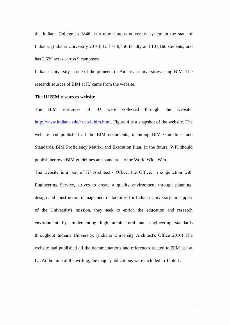
The IU BIM resources website
The BIM resources of IU were collected through the website:
http://www.indiana.edu/~uao/iubim.html. Figure 4 is a snapshot of the website. The
website had published all the BIM documents, including BIM Guidelines and
Standards, BIM Proficiency Matrix, and Execution Plan. In the future, WPI should
publish her own BIM guidelines and standards to the World Wide Web.
The website is a part of IU Architect’s Office; the Office, in conjunction with
Engineering Service, strives to create a quality environment through planning,
design and construction management of facilities for Indiana University. In support
of the University's mission, they seek to enrich the education and research
environment by implementing high architectural and engineering standards
throughout Indiana University. (Indiana University Architect's Office 2010) The
website had published all the documentations and references related to BIM use at
IU. At the time of the writing, the major publications were included in Table 1.

17
Figure 4: Indiana University BIM website (April; 2010)
Table 1: The files that had been published by IU by the end of March, 2010
File Name Format Date
IU BIM Guidelines and Standards for
Architects, Engineers, & Contractors
.pdf Published 9/10/2009
IU BIM Proficiency Matrix .xls Revised 11/9/2009
listing of consultants and contractors that
have submitted their IU BIM Proficiency
Matrix
.pdf Published 3/8/2010
IU BIM Execution Plan Template .doc
IU IPD Template .doc
COBie2 template .xls
COBie2 example .xls
IU Revit CAD layer export mapping file .txt
IU Revit CAD import lineweights file .txt
IU-BIM Guidelines
The BIM Guidelines was an important document not only for the BIM at IU but also

18
for the research of BIM at college campuses. It was issued on Sept. 10th
, 2009. The
BIM Guidelines mainly defined BIM roles and responsibilities of all the project
participants (owners, designers, engineers, contractors, O&M managers) in the
project processes, from pre-design to commissioning. The BIM Guidelines applied
to IU A/E selections advertised on or after October first, 2009 for the projects with
total funding of $5M or greater. (Indiana University Architect's Office 2009)
The BIM Guidelines had five major components: Chapter 1 (Requirements) defines
software requirements. The deliverable file format for all BIM project models is to
be .RVT (Autodesk Revit). Other software, include civil, geo-referenced, and
collaboration software must be interoperable with Autodesk Revit.; Chapter 2
(Process) defines the submission process of two other important documents- BIM
Execution Plan and IPD Methodology Plan, the chapter also defines and identifies
model quality, energy requirements and design deliverable schedule and milestones,
from conceptual phase to construction documents; Chapter 3 (Objectives and
Application) defines the detailed BIM requirements for each project phase, from
Pre-Design to Commissioning. Each phase has subcategories such as general, energy
requirements, deliverables. Along with the BIM requirements, the Guidelines
establishes the methods as to how BIM is being transferred from the project
beginning to the ending; Chapter 4 (Ownership and Rights of Data) claimed the
ownership of all CAD files, BIM files, and Facility Data belonged to IU; Chapter 5
(Terminology) is a list of terminologies that would occur during the projects and in

19
the documentations.
BIM Execution Plan
The intent of this BIM Execution Plan is to provide a framework that will let the
owner, architect, engineers, and construction manager deploy building information
modeling (BIM) technology and best practices on this project faster and more
cost-effectively. This plan delineates roles and responsibilities of each party, the
detail and scope of information to be shared, relevant business processes and
supporting software. (Indiana University Architect's Office 2009)
The BIM Execution Plan shall be submitted to Indiana University by the design
team within thirty (30) days of contract award (Figure 5). The BIM Execution Plan
will be reviewed and approved by Indiana University within fourteen (14) days after
Figure 5: BIM Execution Plan and IPD Methodology Plan submission process
the submitting of the BIM Execution Plan (Indiana University Architect's Office
2009). The BIM Execution Plan identified roles and responsibilities of project
participant in a BIM environment.
IU IPD (Integrated Project Delivery) Methodology Plan
The IPD Methodology Plan shall be submitted to Indiana University within thirty
(30) days of contract award (Figure 5). The IPD Methodology Plan will be reviewed
Design Team
Submit to IU within 30 days
of contract award
IU review and approve
within 14 days of submitting
20
and approved by Indiana University within fourteen (14) days after the submitting of
the IPD Methodology Plan. The IPD Methodology Plan shall demonstrate a high
level of integrated design while identifying project team members and how they will
interact with each other during the project. This plan will include a critical path
methodology on modeling procedures and model information validation. Examples
of IPD Methodology plans are, but are not limited to, Reverse Phase Scheduling and
Critical Path Modeling. The IPD Methodology Plan will be a part of the final bid
documents.
The template of IPD Methodology Plan is drafted by IU’s architect’s office. The
intent of the plan is to formalize a desire to see higher levels of integration within
the design and construction process than traditional methods.
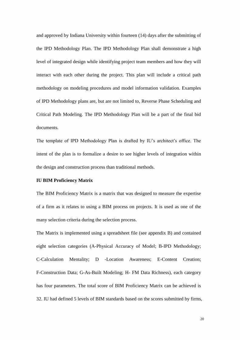
IU BIM Proficiency Matrix
The BIM Proficiency Matrix is a matrix that was designed to measure the expertise
of a firm as it relates to using a BIM process on projects. It is used as one of the
many selection criteria during the selection process.
The Matrix is implemented using a spreadsheet file (see appendix B) and contained
eight selection categories (A-Physical Accuracy of Model; B-IPD Methodology;
C-Calculation Mentality; D -Location Awareness; E-Content Creation;
F-Construction Data; G-As-Built Modeling; H- FM Data Richness), each category
has four parameters. The total score of BIM Proficiency Matrix can be achieved is
32. IU had defined 5 levels of BIM standards based on the scores submitted by firms,

21
the top level is “ideal”, scoring 29-32; the bottom level is “working towards BIM”,
scoring between 0-12. By March 19, 2010; 24 firms had submitted their Proficiency
Matrix to IU (see appendix C).
2.2.3.2 Pennsylvania State University
Pennsylvania State University (PSU) published BIM Project Execution Planning
Guide Version 1.0 (hereinafter referred to as the “Guide”) on October 8th
, 2009. The
Guide was developed by the Computer Integrated Construction Research Program at
the PSU, and was sponsored by funding institutions such as The Charles Pankow,
and the Pennsylvania State University Office of Physical Plant.
The document provides development of a BIM Project Execution Plan by PSU. The
purpose of BIM Project Execution Plan is to ensure that all parties are clearly aware
of the opportunities and responsibilities associated with the incorporation of BIM
into the project workflow. (Pennsylvania State University 2009)
This guide outlines a four step procedure to develop a detailed BIM Plan, as shown
in the Figure 6 below. The procedure is designed to steer owners, program managers,
and early project participants through a structured process to develop detailed,
consistent plans for projects. The four steps include:
1) Identify high value BIM uses during project planning, design, construction and
operational phases;
2) Design the BIM execution process by creating process maps;
3) Define the BIM deliverables in the form of information exchanges;

22
4) Develop the infrastructure in the form of contracts, communication procedures,
technology and quality control to support the implementation (Pennsylvania State
University 2009)
The first step is to identify the appropriate BIM uses based on project and team
goals. Figure 7 lists twenty-five possible uses for consideration on a project. The
Guide had provided a method for identifying appropriate BIM uses for a target
project.
Figure 6: The BIM Project Execution Planning Procedure (Pennsylvania State University 2009)
The second step in the Guide is to design the BIM Project Execution Process, after
each BIM use is identified. The Guide developed a procedure to design the BIM
Project Execution Process. The process map developed in this step allows the team
to understand the overall BIM process, identify the information exchanges that will

23
be shared between multiple parties, and clearly define the various processes to be
performed for the identified BIM Uses. (Pennsylvania State University 2009)
After the process map has been developed, the next step would be defining the
requirements for information exchanges. The Guide presented a method for defining
information exchange. In order to accomplish the tasks, an Information Exchange
Worksheet was designed.
The final step in the Guide is to identify and define the project infrastructure for the
BIM Project Execution Plan. Nine categories were listed to support the
infrastructure, as is shown in the figure below.
Figure 7: BIM Uses throughout a Building Lifecycle (Pennsylvania State University 2009)

24
Figure 8: BIM Project Execution Plan Categories
2.2.3.3 What WPI can learn from IU and PSU
Table 2: The differences between WPI, IU and PSU (Source: Wikipedia).
WPI IU PSU
Type Private Public Public
Faculty 324 2,965 8,626(full and part
time)
Students 4,027 42,347 94,301
Campus 80 acres 1,937 acres 5,448 acres
Location Worcester; MA Bloomington, IN University Park, PA
Administrative
facility
department
Department of
Facilities
The University
Architect's Office
and Engineering
Services
Office of Physical
Plant
WPI should understand the differences among the three colleges. Table 2 compares
WPI, IU and PSU in many aspects. It is easily concluded from the table that WPI is
much smaller than IU and PSU, in terms of number of students and quantity of

25
facilities. So WPI may not have as many construction activities as IU or PSU.
However, WPI can still learn the concept and process of BIM implementation.
Firstly, WPI should realize the importance of standardization for implementing BIM,
both IU and PSU have published very detailed guidelines for delivery strategies,
model quality, organization responsibilities, etc. WPI should publish its own BIM
standard eventually.
Secondly, the real project experience is very important. The detailed requirements in
BIM standard (e. g. energy requirements) should be based on WPI’s experience and
situation. In most cases, WPI needs to collaborate with design team or contractors to
define the requirements.

26
3. Methodology
The objective of this research is to set up a conceptual BIM guideline for facility
management at WPI. The methodology used in attaining this research objective
includes literature review, case study, group meeting and presentations, interviews,
and previous research of WPI students.
3.1 Literature Review
In order to learn and understand the use of BIM at industry and at college campuses,
a literature review was conducted. The goal of the literature review was to get an
understanding of the application and research of BIM in industry and academic
institutions. Also, the construction industry situation, operations and maintenance of
a building were another important aspect of the literature review. The literature
reviewed consisted of IQP and Master’s thesis report of WPI students, white papers,
journals, websites, and other industry related publications.
3.2 Case Study
The purpose of the case study is to explore and understand the details involved in
implementing BIM for the facility operation and maintenance for college campuses.
The case study consisted of two sections, the individual building section and
inter-building system section. The Kaven Hall
(http://www.wpi.edu/about/tour/kaven.html) was chosen to develop a case study of

27
individual building based on a Revit model. The original Kaven Hall Revit model
was developed by a group of WPI students through their IQP projects using 2D
drawings and Revit Architecture. The model contained the architecture portions of
Kaven Hall, and did not include structure and MEP part, but it is still good enough
to support this research. Another reason for choosing Kaven Hall was that Kaven
Hall is the home of Civil and Environmental Engineering and facility and equipment
in the building can easily get accessed and updated in the future.
Autodesk Revit is the BIM tool used for developing the case study. Revit was
chosen because the wide spread of applications, people in the AEC/FM industry
understand it much; the computers of WPI Civil and Environmental Engineering
Department has installed Revit. Other programs, included Autodesk Design Review,
Google Earth, and Autodesk Civil 3D, have also been used to support the
development of model.
The final Kaven Hall model consisted of two parts, the architecture part and the
operation and maintenance part. The architecture of Kaven Hall was updated from
the original one, which was developed by an IQP group (Halilaj and Mills 2006).
The facility model was built up based upon the needs expressed by the Department
of Facilities and lab manager at Kaven Hall. The information is critical to the
success of the case study because users’ needs from BIM is important, which means
the scope and level of details of BIM should be defined prior to the implementation
of BIM. Then, based on the information, the facilities and equipments were added
28
into the model.
The methodology of developing the inter-building model was similar to Kaven Hall
model. Firstly, the WPI Revit site plan was created, by importing surface from
Google Earth. Secondly, based on the needs of facility management at WPI, a
sample inter-building systems, including water, sewer, fire, steam systems were built
up. Other building models were contributed from other WPI students; the Salisbury
Labs was developed by Chris Keegan (2010), Bartlett Center model was developed
by Ronald Mendez (2006).
To better determine the practicality of using the model, a BIM model viewer
program was used by the end users. Autodesk Design Review is a free viewer
program designed to view DWF files. The DWF files are created from the Revit file
and allow users to view and navigate the model through the internet. From Design
Review, users can view the same information as from Revit, but cannot modify it.
3.3 Group Meeting and presentations
In order to enable industry, WPI Department of Facilities and the academic
community to have better communication and collaboration and to explore the
potential use of BIM at WPI, a group was established in 2009. One purpose of the
BIM group is to serve as thesis resource for the author. The BIM group members are:
Guillermo Salazar, professor at WPI Department of Civil and Environmental
Engineering; Alfredo DiMauro, Assistant VP for Facilities; Elizabeth Tomaszewski,

29
Facilities Systems Manager; Laura Handler, Virtual Project Manager at Tocci
Building Corporation; and Christopher Keegan, graduate student at WPI. Group
meetings were set up regularly among committee members approximately every
month from September 2009 to April 2010.
The thesis author gave a presentation in December 2009 for the Department of
Facilities, to introduce the concept explored by thesis and to receive feedback from
them in terms of level of interest and data needs.
3.4 Previous BIM-Related Studies at WPI
An Interactive Qualifying Project can support the thesis research, the Interactive
Qualifying Project, or IQP as it is known on campus, is WPI's most distinctive
academic requirement, and is unique in higher education. The IQP challenges
students to address a problem that lies at the intersection of science or technology
with social issues and human needs and is done under the direct guidance of one or
more faculty advisors, usually in teams of 2-4 students. (Worcester Polytechnic
Institute 2010)
The IQP used in this research was the latest IQP among the series of IQPs that were
conducting research with the “e-buildings”. The IQP was titled “WPI Building
Information System” (Figure 9), by Sibora Halilaj and Andrew Mills and co-advised
by Professor Carrera and Salazar as well as former director of WPI physical plant,
Mr. John Mills. It had conceptually provided information on Goddard Hall, with the

30
building synopsis, safety features, floor plans, work orders, and inspections were
identified. The IQP project had also listed all the buildings and residential halls on
campus, which would conceptually expand the knowledge and experience gained in
Goddard Hall into the whole campus.
Figure 9: An IQP slide of Andrew Mills and Sibora Halilaj
The report and presentations of these IQP were reviewed, from where creative
thoughts and concept were gained. For example, Sibora and Andrew’s IQP identified
all the building safety features for Goddard Hall (on WPI campus), and the features
would be also available for other buildings. Some of the knowledge in this IQP have
been used in the research.

31
3.5 Interviews
Four managers and directors at WPI’s Department of Facilities were interviewed.
They were Michael Lane, Director of Facilities Operations; David H. Messier,
Manager of Environment & Occupancy; Christopher L. Salter, Director of Project
Management & Engineering; and Elizabeth Tomaszewski, Facilities Systems
Manager.
The interviews served to collect information and feedback about potential use of
BIM and for the facility management department. Before the interview, the
objectives had been set; then, the model was shown to them; and finally, ask them
four simple but fundamental questions:
1. What does the model has but you do not need?
2. What does the model do not have but you need?
3. What other information do you use that could be coordinated with BIM?
4. How and who should access to the information?
In addition, the interviews served to research the current practices of information
management by the Department of Facilities, among them the use of Maximo, a
system used by facility management for the work order process of operation and
maintenance.

32
4. Case Study
The objectives of the case study are to address the following fundamental issues:
The feasibility of BIM based information system for the facility management at
WPI
Explore what should be modeled.
Determine the appropriate level of details of the model.
Determine how to create and manipulate the model.
The case study for this research consists of two sections; the first section
concentrates on individual building model, which is Kaven Hall. The purpose of
using the individual building model is to illustrate the feasibility of using BIM for
each individual building in the college campus. The proposed model should include
enough information on the floor plans, elevation plans, and facilities & equipment
based on the needs of the facility management department. The second section
studies the inter-building systems, which are the water systems, electric systems,
plumbing systems, fire systems, heating systems that connect the buildings in the
campus.
The author interviewed the managers and directors at the Department of Facilities to
collect information on what they need from BIM information system. Then, the
author built up the model to include all the facilities and equipment based on the
interviews.

33
4.1 The individual building section
A Kaven Hall Revit model (Figure 10) was developed to conduct the case study. The
model was originally developed by a group of WPI students to fulfill their IQP
(Interactive Qualified Projects) using Revit Architecture. The author chose Kaven
Hall as a sample of case study for three reasons: first, the model was built very
accurately and the floor plans and elevations were most updated compared to other
Revit models; second, Kaven Hall is the home of Department of Civil and
Environmental Engineering and therefore would be easy to get access to the
information of facilities and rooms; third, the Kaven Hall is a good sample for the
coordination of MEP, Fire Safety, and Environmental Safety systems.
Figure 10: Kaven Hall - Department of Civil and Environmental Engineering
The original model contained general information of floor plans and elevations, as
well as the topography of surroundings; also, it contained some information of

34
egress way and lab equipment. However, the usefulness of the information for
facility management contained in the model needed to be queried. In order to make
the case study more useful for the facility management, the author interviewed with
several staff at the Department of Facilities, including Elizabeth Tomaszewski,
Facilities Systems Manager; Christopher Salter, Director of Project Management &
Engineering; David Messier, Manager of Environment & Occupancy Safety; and
Michael Lane, Director of Facilities Operations. Christopher was interested in the
inter-building system of water, steam and electrical. David was more concerned
about the Fire Safety and Environmental Safety of WPI physical plant; he did
semi-annual report of Building Safety Inspection and weekly report of WPI
Hazardous Waste Storage Area Inspection. From the interview with him, the location
of Chemical Fume Hood, Bio-Safety Cabinets (BSC), Emergency Showers, Wash
Units, Fire Suspension systems were the most important information to have in
order to conduct his work. He would like to see some related parameters like
installation date, inspection date, etc. Table 3 lists the building components that have
been included in Kaven Hall model. Liz and Mike, on the other hand, were
interested in how BIM are connected to Maximo Work Orders. Maximo Work Order
is the current system used to manage information on maintenance & operations.
Figure 11 illustrates the standard work order flow; it is generated by the requester at
a given building, and ends up at the office of Facility Management.

35
Table 3: Parameters of Kaven Hall
Architecture
and site plan
Generic floor plans with room occupancy; generic ceiling plans;
generic elevation plan; windows; doors; stairs; roof; surrounding
site plan; furniture of some rooms
Safety features Locations of fire extinguisher, fire alarm, smoke detector, exit sign,
emergency lighting, chemical fume hood, emergency shower,
inspection, and sprinkler head.
Mechanical Location of sprinkler pump; steam; electric panel
In order to identify the locations and parameters of those systems mentioned above,
the author went around the whole building with the 2D drawings and checked the
physical inventory, besides, for the private areas that the author cannot get access
personally, Donald Pellegrino, the lab manager at the department helped the author
to get access.
After gathering up all the information for the Kaven Hall model, the facility objects
and parameters were add into the model, which the original one did not have. In
order to add a new kind of object into the model, a family needed to be downloaded.
In Revit, a family is a group of elements with a common set of properties,
parameters and a related graphical representation. (Autodesk 2009) The same kind
Send to Respected
Trades Department
Facilities Office
generated “Work
Order” Send Service Request through Maximo Requester
Trades Reviewed Work
Order, Complete Work
Order
Turn into office
Figure 11 : Work Order Flow of WPI facility management

36
of elements may have different values under one family, the variations within the
family called types. For instance, the Furniture family includes families and family
types that you can use to create different pieces of furniture, like desks, chairs, and
cabinets. The appropriate families for the model update were downloaded from the
internet. Revitcity (http://www.revitcity.com/index.php) is an internet community
that serves BIM users, from where the appropriate families and objects were
downloaded. The locations and the types of the facilities were not 100% accurate,
but roughly based on the manual drawings; so for the future work, it would be better
to be provided with the accurate information. Figure 12 and Figure 13 illustrate the
floor plans and ceiling plans of first floor of Kaven Hall. The ceiling plans mainly
contained exit signs, emergency lights, sprinkler heads, and smoke detectors. The
floor plans contained fire alarms, fire extinguishers, lab safety equipments, and
mechanical equipments.
Figure 12 Ceiling Plan of first floor

37
Figure 13: Floor Plan of first floor
The inter-building systems section
The reason to create a model showing the inter-building systems is totally targeted to
meet the needs of the facility management department. Through the interviews with
the Department of Facilities at WPI, the managers and directors were excited to see
the potential uses of BIM for the systems like pipes, ducts, and wires underground,
which cannot be efficiently represented in a 2D system.
The objects and elements included in the inter-building system model were Kaven
Hall Revit model, Salisbury model, Goddard Hall model, campus topography
surface, and sample pipes between buildings.
Figure 14 is a sample of the inter-building systems; the three buildings, Salisbury
Labs, Kaven Hall, and Goddard Hall, are located in the main campus of WPI. The

38
“lines” between the buildings are pipes underground. It is necessary to point out here
that the systems provided in the model were not accurate but was made up only for
illustrating on how BIM could be used for this purpose.
Figure 14: Inter-building systems
Figure 15: WPI campus topography map
39
The buildings actually sat on the campus map in the model (Figure 15); the brown
area is the 3D WPI topography surface, which was imported directly from Google
Earth. The topography was hidden in Figure 14 just for illustrating the systems
clearly. The topography information is useful for the facility management. Because
the buildings on the same area may “seat” on different elevations, the structure of
inter-buildings systems would be influenced by the elevations and the locations of
building and the depth of the location of utilities can be clearly established.
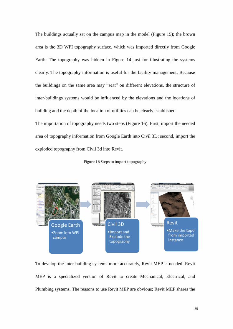
The importation of topography needs two steps (Figure 16). First, import the needed
area of topography information from Google Earth into Civil 3D; second, import the
exploded topography from Civil 3d into Revit.
Figure 16 Steps to import topography
To develop the inter-building systems more accurately, Revit MEP is needed. Revit
MEP is a specialized version of Revit to create Mechanical, Electrical, and
Plumbing systems. The reasons to use Revit MEP are obvious; Revit MEP shares the
Google Earth
•Zoom into WPI campus
Civil 3D
•Import and Explode the topography
Revit
•Make the topo from imported instance
40
same platform with Revit Architecture, and is totally interoperable with Revit
Architecture, partially interoperable with Autodesk Civil 3D and AutoCAD. Also,
Revit MEP is better than Revit Architecture in terms of building up pipes, ducts, and
wires.
Ideally, to build up the pipes, ducts, and wires in the model, the exact directions,
connections, locations, and slopes are needed. However, in this research, the systems
location does not need to be accurate. Because based on the interviews, what the
facility managers would like to see is just how pipes, ducts, and wires are connected.
For instance, the pipes from Goddard Hall to Kaven Hall are connected through
Salisbury Labs, not directly connected (Figure 15). Additionally, the facility
managers want to see some parameters of the systems, such as the diameters and
materials of the pipes. The Revit system can exactly provide the information as they
want. The dialogue box in the middle of Figure 17 shows the parameters of a sample
pipe. The Table 4 is a list of parameters and values of the pipe from Figure 17. This
has covered all aspects of parameters of a pipe, including the constraints,
mechanicals, and dimensions. Therefore, the proposed inter-building system can
basically satisfy the needs of the facility management for WPI, not only for the
visualization purpose, but also can be an ideal database of facilities.
The systems for end users
Revit is an excellent database but not a convenient way to extract and restore
information for daily use. Revit is slow of running in personal or normal computers

41
and is very complex for those who do not have knowledge in BIM. The end users of
the facility information, such as facility management and space planning, need a
simpler and faster tool to convey and restore information. Autodesk Design Review
can be an ideal tool for this.
Figure 17: The parameters of the pipe in Revit MEP
Table 4: Parameters of a sample pipe
Parameters Value Parameters Value
Horizontal Justification Center Relative Roughness 280.787
Vertical Justification Middle Flow State Laminar
Reference Level Level 2 Friction Factor 0.00000
Offset -7’ 0” Velocity 0 FPS
Start Offset -7’ 0” Friction 0 FT/ 100Ft
End Offset -7’ 0” Pressure Drop 0 Psi
Slope 0” / 12” Section 0
System Type Undefined Area 256.83 SF
Fixture Units 0.000000 Outer Diameter 6 5/8”
Insulation Thickness 0” Inner Diameter 6 17/256”
Invert Elevation 542’ 9” Size 6”
Additional Flow 0 GPM Diameter 6”
Flow 0 GPM Length 163’ 6”

42
Autodesk Design Review is one of the most popular free programs used for
reviewing DWF files. The Revit file can be exported in to DWF files and then can
be opened by Autodesk Design Review (Figure 18). Design Review enables the
users’ entire project or product team to view, print, measure, and markup DWF,
DWG, DXF, PDF and raster files containing 2D and 3D content. Fully integrated
with AutoCAD, Inventor, and Revit, Design Review helps the users easily share
drawings, models, maps, and design data with team members, clients, consultants,
contractors, partners, suppliers, and other reviewers who may not own or know how
to use design software (Autodesk 2009).
Figure 18: The “List View” of Design Review, consists of floor plans, 3D view, ceiling plans, etc.
Due to the small size and high interoperability of Design Review files, the users can
easily exchange them by email, websites, intranets, and physical media, such as
43
DVDs. A previous thesis finished by a WPI graduate student Ronald O. Méndez had
shown that DWF files and Design Review can be published on a website easily and
viewed by common users without major training by the user.
Design Review can be an ideal application for the facility management department.
The interface of the program is simple and thus people can adapt it in a short term.
The presentations and interviews conducted by the author with staff at facility
management department have convinced him that the program is easy to use and
value added to their daily work. So overall, the costs for implementation the systems
would be minimal.
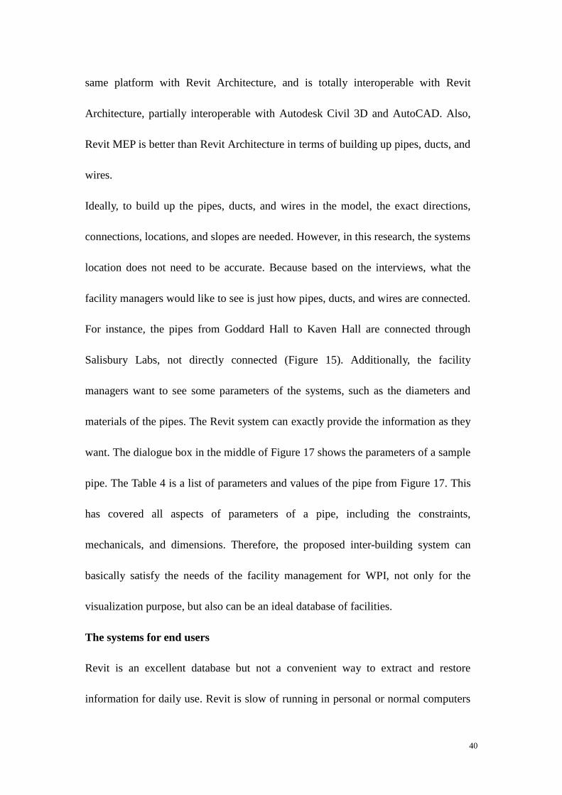
Figure 19: The “Model” view; consists of project properties, quantity takeoffs, etc.
When exporting from Revit, the users can choose which floor plans or 3D views to
be exported. The normal way is to export a 3D view of the whole building, floor
plans, and ceiling plans, if necessary, the users can also export egress way plan, floor
usage plan (by department, by occupancy, or by hours of use, etc.). Also, the DWF

44
can be made to fit specific needs, for example, the DWF file can only contain the
life safety equipment in a building to fulfill the needs of the occupancy safety
management. The default 3D view of the whole building is very important because it
contained all the information of the building, when clicking on it at the “List View”
panel, the 3D view would pop up and all the elements in the building would be listed
in the “Model” panel categorized by families(Figure 20). The user can also go to a
certain element to view the information on it, for example, the user can select a
window (Figure 21) by clicking on either the list or the model, and view the
information on the right panel; the selected items are colored with yellow. The users
can select or view items in different ways, hide, unhide, or transparent.
Figure 20: The view of properties of a window at Kaven Hall
The users can also have cross section views of the building (Figure 22), which
represents a typical section view of floor plan, in order to achieve the effects as
shown in Figure 22, the users need to go to one of the amazing thing the user can do

45
is to select a room and view the room information on the right. Also, the users could
view the building in vertical or angular section (Figure 23), which would help them
easily understand the projects and grab information they want.
Figure 21 Cross Section view of the first floor of Kaven Hall
Figure 22 Lobby cross section of Kaven Hall

46
Figure 23: The DWF file of the inter-building systems.
The Design Review can also view multiple buildings together. Figure 23 is the DWF
file of inter-building system, the topography was hidden for the illustration purpose.
The users can perform the same functions as in the individual building systems, for
example, to view the properties of an object (Figure 24), or to view a section of a
building (Figure 25). Most importantly, users can select a pipe in the system (Figure
26), which means the BIM based information system is feasible for generating and
managing the data of the underground water, steam, fire, sewer systems through its
life cycle.
In summary, the BIM based information system adds value for the existing facility
management at college campuses, because BIM is capable to include the facilities
and equipments in the building or on campus site to fulfill the information needs of
Department of Facilities, and the Design Review program can allow the end users to

47
access and extract information more conveniently. However, the most critical issues
are what to be modeled and how much level of detail should be modeled. Before
Figure 24: Users can select an object in multiple buildings (the yellow roof)
Figure 25: Section views for multiple buildings

48
Figure 26: Users can view the properties of a pipe
WPI implementing BIM, a Charrette needs to be set up. The Charrette is an event in
which to resolve a problem or an issue in a meeting. The less critical issues, such as
who and how to maintain the BIM system, should be addressed based on WPI’
situation.

49
5. Conceptual BIM Execution Plan for
WPI
The purpose of BIM Execution Plan is to effectively integrate BIM into the WPI’s
new project delivery process and existing facility management. The BIM Execution
Plan should standardize the overall requirements and details for the future project
team and facility management to follow. The plan should also define the scope of
BIM, the delivery procedure, the contractual relationship, and the information
exchange method. The proposed plan in this research is a conceptual version,
because the development and implementation of BIM is a long-term activity and
needs participation of a variety of stakeholders. WPI is a beginner on BIM and did
not have any experience on BIM project; so it is unnecessary to document a detailed
plan for WPI right now. The proposed conceptual plan would only provide a basic
BIM guideline for WPI’s further use.
The conceptual BIM execution plan for WPI consists of two sections, the first
section is for new buildings, which is mainly based on other universities’ experience
(e.g. Indiana University and Pennsylvania State University) and the BIM status of
WPI; the second section is for existing buildings and facilities, which is based on the
case study, interviews with WPI staff, and BIM committee meetings.

50
5.1 Conceptual BIM plan for new buildings and
renovations
5.1.1. Overall goals and uses of BIM
Pennsylvania State University had identified 25 BIM uses throughout project life
cycle (Figure 7). However, the BIM uses are at the standpoint of the whole project,
the owner may not have directly benefited from the implementation of BIM. WPI
should help the project participant to identify their specific BIM uses, and also
should focus on the following uses, from where WPI can directly benefit: existing
conditions modeling, cost estimating, maintenance & scheduling, asset management,
space management, and disaster management.
5.1.2. BIM process design
Pennsylvania State University (PSU) uses Business Process Modeling Notation
(BPMN) approach to format BIM processes of a specific project. The BPMN
approach consists of two levels: level 1, BIM Overview Map; level 2, Detailed BIM
Use Process Maps. The Overview Map shows the relationship of BIM Uses which
will be employed on the project. The Detailed BIM Use Process Maps are created
for each identified BIM Use on the project to clearly define the sequence of various
processes to be performed. (Pennsylvania State University 2009)
Each project is unique, so the BIM process should be developed by the project team.
These processes provide a detailed plan for implementation of each BIM use.
WPI’s knowledge and experience on BIM is very limited, the Department of Facility

51
still was not sure if implementing BIM or not. A new WPI recreation center was
prepared to construct at the time of this writing, but the BIM model was created by
the design team and shared with the construction manager for their internal use only
to prepare a site logistics plan. The lonely BIM behavior does not fit the philosophy
of BIM, but still these are benefits derived from this approach when the parties are
willing to share models with no contractual implications.
5.1.3. BIM Scope
WPI should build up a Charrette to discuss the future BIM scope. Charrette is an
event in which a group of stakeholders gather to develop a focused and sustained
effort prior to the deadline of a project. For WPI, the Charrette should include the
decision makers, facility managers, professors, space planners, design team,
constriction team, and consulting team. The Charrette should discuss the level of
details of BIM, the disciplines of BIM. The members of the Charrette should include
facility management department, provost department, space planning and professors.
Through meetings of BIM committee at WPI, the facility management had defined
mechanicals, fire safety, and card access as the primary uses of BIM. So the three
disciplines should be submitted to WPI with accurate and detailed information for
the further uses.
5.1.4. Organizational Roles and Responsibilities
Indiana University has incorporated Collaborative Process Mapping (CPM) (see
Appendix D) in their BIM Execution Plan template. The CPM clearly defined the

52
BIM roles and responsibilities of each project participant for each phase.
Pennsylvania State University utilizes BIM uses to identify which organization will
staff and perform that use.
WPI should refer to both universities’ experience and develop the roles and
responsibilities of project parties for both individual project and the overall WPI
facility management.
5.1.5. Delivery Strategy / Contract
IU implements IPD (Integrated Project Delivery) mandatorily for all the projects.
IPD Process Proposal is the contractual documents to be signed by owner, designers,
and contractors. The purpose of the IPD Process Proposal is to achieve higher level
of integration of project design and construction than the traditional delivery
process.
PSU did not mandatorily use any delivery strategy, but suggested on how to select a
BIM based strategy and how to write a contractual document.
WPI is familiar with traditional delivery methods but in recent years, the
construction management at risk (CM at risk) has been consistently used. The
development of Campus Center and Bartlett Center used design-bid-build method,
whereas, the on-going Recreation Center project, and the recently completed East
Hall used CM at risk. WPI has minimum experience on Design Build but has no
experience with IPD strategy. When using a less integrated delivery structure, it is
important to work through an initial BIM Execution Process and then assign roles

53
and responsibilities in the contract structure (Pennsylvania State University
2009).WPI should document the roles and responsibilities carefully since BIM can
not only change the traditional process but also can increases the degree of
communication. Lonely BIM is accepted and encouraged at the beginning of the
adoption of BIM to gain knowledge and experience, as well as reducing risks, but
social BIM may be strongly encouraged in experienced team participants.
Collaboration is of particular importance for that BIM affects the degree of change
in the project delivery process.
5.1.6. Communication Procedures
PSU recommends developing electronic and meeting communication procedures,
including model management and standard meeting actions and agendas.
WPI should utilize the current electronic communication resources (e.g. MyWPI,
eMail system) to manage documents in BIM projects. Due to the large files of BIM,
some communication tools may need to be upgraded. WPI should build BIM server
for facility management department, and the server can be located at Computing &
Communication Center (CCC), where the Maximo server is located. The server
should support a set of system that can upload, download, edit, and collaborate
within project stakeholders. Also, the document management (file folder structure,
permissions and access, folder maintenance, folder notifications, and file naming
convention) should also be resolved and defined.
WPI should help set up a Charrette for regular BIM project meeting. The Charrette

54
meeting should be scheduled based on the following procedures, which is
recommended by PSU.
• Identify all stakeholders to participate in a meeting which will be using model
• Develop a schedule for any meeting which reference to model content
• Define procedures and protocols for the submission and approval of the model
as appropriate.
5.1.7. Technology Infrastructure Needs
The BIM authoring software models should be .rvt format (Autodesk Revit).
Because Revit is one of the most popular BIM tools in United States; WPI owned
license of Revit in the laboratories of civil engineering, the professors, staff, and
students are familiar with Revit. Moreover, the industry leader contractors, such as
Gilbane, are using Revit. Indiana University uses Revit for BIM authoring software.
The civil engineering software can be Autodesk Civil 3D, because they are both
designed by Autodesk and are highly interoperable. The case study had tested the
interoperability.
The coordination and collaboration tools can be .NWD format (Navisworks). With
Autodesk Navisworks, project teams can collaborate, coordinate, and communicate
more effectively to reduce problems during design and construction. Indiana
University uses Navisworks for collaboration and coordination; uses ProjectDox for
document management and file sharing.

55
5.1.8. Model quality
Defining model quality is hard because a BIM model typically contains thousands of
items and parameters. Quality control methods should be defined and implemented.
PSU recommended defining BIM model quality based on the following criteria,
which were also applicable to WPI:
• Reference model files to a common origin so that they are easy to integrate; for
example, the Revit coordination system is controlled by Base Point and Survey
Point. The project base point defines the origin (0,0,0) of the project coordinate
system. The survey point represents a known point in the physical world, such
as a geodetic survey marker. To ensure the integration of model for all parties
and disciplines, project team must define the base point and survey point.
• Define a file naming structure for all designers, trades, and subcontractors. Just
like paper files, electronic files need to be well-organized and labeled correctly
so that they are identifiable and accessible by team members. (Department of
Cultural Resources 2008)
• Define an agreement on model accuracy and tolerances. The model of a project
participant may have influenced on other team members work. So the tolerances
of the model must be defined beforehand so that the responsibilities of each
project participant are clear.
Meanwhile, PSU suggested using four methods to check the model accuracy: Visual Check,
Interference Check, Standards Check, and Element Validation (Pennsylvania State
56
University 2009). National Building Information Modeling Standard (published by National
Institute of Building Sciences) is good reference for model checking and quality control.
5.2 Conceptual BIM plan for existing buildings and
facilities
Existing buildings and facilities contain relatively static data. The data is to support
the facility operations, occupancy management, and project management on college
campuses. Traditional data storage method is 2D system, which is paper documents,
CAD drawings, or PDF files. The storage method system is fragmented and
inefficient when it comes to retrieving and updating the parameters for a piece of
facility or equipment. For example, when upgrading the current smoke detector with
newer styles, the entire ceiling plans ought to be changed. It may take time and
effort to maintain the 2d data with the existing inventory. However, BIM is an
effective carrier to host, exchange, and upgrade the information. Revit, web page,
and other related programs will be used for the media.
The conceptual BIM plan for existing facilities will propose methodologies on what
to be included in the plan and how the plan works. The knowledge and experience of
the plan is based on the case study, Ronald Mendez’s master’s thesis, an IQP project
by Sibora and Andrew, and the experience from BIM committee. The plan will
consist of three parts: 1. the modeling guideline; 2. the interface for end users; 3.
information maintenance and upgrade.

57
5.2.1. The modeling guideline
The case study in Chapter Four had illustrated the feasibility of BIM based
information system for college campuses. The case study utilized Kaven Hall as a
sample of individual building, and used Goddard Hall, Salisbury Labs as
supplementary samples for inter-building systems. The Kaven Hall model has been
tested as a qualified solution. Goddard Hall model and Salisbury model were
finished to fulfill other academic requirements and therefore may not be qualified
models for BIM based information system, but these models can be updated based
on what the author did with Kaven Hall.
WPI needs guidelines to standardize the modeling process. WPI owns 39 buildings
on and off campus, and for 28 of them there are files of 2D drawings. Typically, the
shell of the building model is built up by the original 2D drawings. But the locations
and parameters of equipments and devices (e. g. sprinkler heads) need both the 2D
drawings and physical inventory check.
The Department of Facilities has concluded a building modeling priority list, which
lists the buildings that are necessary to be modeled in a short term. The buildings on
the list have complex structure and facilities and need to be managed in BIM. The
houses off campus are relatively small and the information can easily retrieved from
walk through and experience, so BIM may not be necessary to those houses.
The next issue is to determine who are going to do the modeling job. Students are
good resources; they are low cost, creative and faster learners. They can build up the

58
models through academic projects. However, students cannot guarantee the quality
and accuracy of the models. They are probably beginners on BIM and may require a
lot of training. Architects or third party consultants are the best choice when it
comes to finishing the modeling with desired quality and schedule. They are more
familiar with BIM tools and can deliver the work effectively. So WPI needs to go
through the selection process and sign contract with architects or consultants.
The final issue is what to model. The case study in Chapter Four had already given
the answers. It would include the architectural part of the building, the fire safety
equipment, life safety equipment and egress system inside the building, and the
water, steam, sewer, and fire systems between the buildings.
5.2.2. The interface for end users
A proposed website (http://users.wpi.edu/~zijia_liu/index.html) was designed for the
facility management department. The website would serve to deliver the information
to the end users and share knowledge and experience with externals. Figure 27 is the
structure of the website. The website has four major sections: introduction; building
list; downloads; and related links. The Introduction section (Figure 28) should
document several paragraphs that explain the recent development of BIM at WPI, in
order to gain interest from future BIM project participants, scholars, industry leaders,
and other universities. The Building List section will serve as a central database for
buildings and facilities (Figure 30). The webpage lists all the buildings on campus,
including residential halls. When users click on a hyperlink (Kaven Hall in this case),

59
detailed features of each building will be displayed (Figure 29). The 3D model, floor
plans, and ceiling plans are DWF files and are opened by Design Review program,
the interface and functions of the program remain the same in a webpage as in the
original Revit model (Figure 19). For example, the users can select the roof in
Kaven Hall model and view the information (Figure 31). Under the link of Space
Utilization are figures that exported directly from Revit model. The inspection and
commissioning can be scanned documents; the research by Ronald Mendez had
proved the feasibility that includes commissioning documents in a website, along
with Revit models. Also, the schedules of the model can be uploaded to the website
(Appendix F). The Downloads section can be a database that serves for downloading
all the future BIM plans for WPI, just as the webpage of Indiana University BIM
Standards (Figure 4).
Figure 27: The hierarchical structure of proposed website
Home Page
Building List
Kaven Hall
Revit Model Space UtilizationFloor and ceiling
PlanInspection Commissioning
Salisbury LabsCampus Center;
etc.
Downloads Related Links

60
Figure 28: The Home Page of proposed website for WPI BIM Center
Figure 29: Features in each building
5.2.3. Information maintenance and upgrade
BIM models need to be maintained and upgraded regularly to fulfill the information
requirements of facility management department. Currently, WPI is using Maximo
work order for the process of maintenance and operation. But this process was only
kept in files. The Maximo work order should be coordinated with BIM for better

61
visualization and control. This methodology for proposed information maintenance
is based on the original Maximo work order and manual update.
Figure 30: Building List section of proposed website
Figure 31: The Kaven Hall model in a webpage
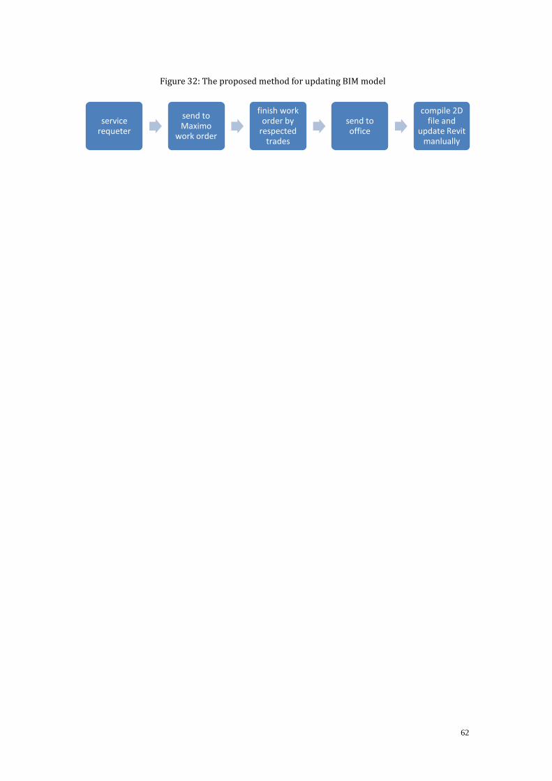
62
Figure 32: The proposed method for updating BIM model
service requeter
send to Maximo
work order
finish work order by
respected trades
send to office
compile 2D file and
update Revit manlually

63
6. Conclusions & Recommendations
BIM has quickly gained momentum as the technology brings greater collaboration
and communication between project participants. Half of the AEC/FM industry is
using BIM or BIM-related tools today (McGraw Hill Construction 2009); and the
number of BIM users will increase exponentially in the next few years. Designers,
contractors, and owners have seen the benefits that are directly or indirectly brought
up by BIM. The time spent on design and construction can be shortened due to the
3D visualization and coordination, the owner can enjoy the benefits taken by the
reduced schedule. Needless to say, the quality of the project can be improved, the
fabrication and construction waste are reduced by the new technology. The owner
can receive more valuable as-built information when the project was completed. And
therefore the facility management can use more accurate, interoperable, and
accessible information system for operation and maintenance.
However, two major hurdles had blocked the implementation of BIM. The first
hurdle is that the legal responsibilities among project participants in which BIM
practice has not been mature enough. Users prefer to use BIM internally for the first
several BIM projects or they develop a lonely BIM before they have the capabilities
to handle an integrated environment. The second problem lies with the training costs
related to use these programs. BIM tools are complex and require professional
teaching to master the practical jobs.

64
Besides the limitations, the facility managers are starting to focus on BIM for the
future information management style. Owners such as Sandia Labs are exploring
ways in which BIM can enhance the efficiency of operation and maintenance of the
existing buildings. Colleges such as IU and PSU have documented BIM guidelines
for new projects to clearly identify the roles and responsibilities of BIM project
participants.
The conceptual BIM plan for WPI is just a schematic guideline that originates the
BIM implementation work. In order to fully implement BIM for WPI’s new
construction and operation and maintenance, valuable experience is needed. WPI
needs to develop detailed BIM plan gradually along with gaining experience from
industry, peer colleges, and real practical experience. One suggestion is that WPI can
start from small projects like underground piping renovation; the project can utilize
the concept and methodology of the inter-building system in the case study of this
thesis. Another issue is that WPI needs to set up a modeling team to manage and
update BIM models in regular base. The team can consist of professors, professional
BIM expert, staff and students at WPI. The BIM team can also in charge of teaching
and training BIM knowledge and philosophy for the facility management
department. Moreover, the regular WPI BIM group meeting should be held more
frequently to discuss thorough issues that WPI has encountered.
For the future work, the most important is to resolve the interoperability issue
between Maximo and Revit. Maximo is better in generating work order process

65
while Revit is good at restoring and communicating information. The two sets of
information management style cannot be achieved automatically in a single work
flow. Currently, the proposed method is just manually updating Revit model after
collecting work order files from Maximo. Another issue is that the inter-building
system needed to be developed in more accurate way. The case study just illustrates
sample pipes between buildings; the future work should focus on how to build up
pipes from 2D drawings with correct parameters. The most intriguing point is that
continue developing the website, which serves as a central BIM database for facility
management. The website had already been built up with structured solution; the
next step is just post the models, plans, files and documents under the exact
hyperlink.
66
Bibliography
ASHRAE. An Introduction to Building Information Modeling. American Society of
Heating, Refrigerating and Air-conditioning, 2009.
Autodesk. "Autodesk Design Review 2010 Help." (Autodesk) 2009.
Autodesk. Revit Architecture 2009 Families Guide. 2009.
Autodesk. "Revit Tutorial 2010." Revit Tutorial 2010., 2009.
BIM Resourses. 2009. http://bim.arch.gatech.edu/ex_format3.asp?id=549 (accessed
2010).
Chuck, Eastman, Paul Teicholz, Rafael Sacks, and Kathleen Liston. BIM Handbook
- A Guide to Building Information Modeling. Wiley, 2008.
Contractors Center Point. Improving Your Construction Design Process Through
Building Information Modeling. April 12, 2010.
http://www.contractorscenterpoint.com/2010/04/improving-your-construction-desig
n-process-through-building-information-modeling.html (accessed April 20, 2010).
Department of Cultural Resources. Best Practices for File-Naming. Department of
Cultural Resources, 2008.
Eric Lamb, Dean Reed and Atul Khanzode. "Transcending the BIM Hype: How to
Make Sense and Dollars from Building Information Modeling." AECbytes
Viewpoint (AECbytes), 2009.
Georgia Institute of Technology. BIM Resources. 2009.

67
http://bim.arch.gatech.edu/ex_format3.asp?id=549 (accessed April 2, 2010).
Goldberg, Edward. State of the AEC industry: BIM implementation slow, but
inevitable. CADanalyst, 2005.
Halilaj, Sibora, and Andrew Mills. An Integrated Building Management System for
the WPI Campus. Worcester: Worcester Polytechnic Institute, 2006.
Handler, Laura. Hollywood BIM. September 24, 2009.
http://bimx.blogspot.com/2009/09/hollywood-bim.html (accessed April 11, 2010).
Holness, Gordon V.R. "BIM Gaining Momentum." ASHRAE Journal (ASHRAE),
June 2008: 28-29.
Indiana University Architect's Office. Architect's Office. 2010.
http://www.indiana.edu/~uao/ (accessed March 19, 2010).
Indiana University, BIM Execution Plan. 2009.
Indiana University, Building Information Modeling (BIM) Guidelines and Standards
for Architects, Engineers, and Contractors. 2009.
Indiana University. Indiana University. 2010.
http://en.wikipedia.org/wiki/Indiana_University.
Institute of Electrical and Electronics Engineers. IEEE Standard Computer
Dictionary: A Compilation of IEEE Standard Computer Glossaries. New York, NY:
IEEE, 1999.
Krol, Jason, and Philip Braut. E-buildings -- An information management system for
facilities management on the WPI campus. IQP Report, Worcester: Worcester

68
Polytechnic Institute, 2005.
Lee, Ghang. "Specifying parametric building object behavior (BOB) for a building
information modeling system." Automation in Construction (Automation in
Construction) 15 (2006): 758-776.
McGraw Hill Construction. "The Business Value of BIM." BIM Smart Market
Report, 2009: 5-6.
McGraw Hilll Construction. "BIM Smart Market Report." Building Information
Modeling (McGraw Hilll Construction), 2008: 2.
Méndez, Ronald O. "The Building Information Model in Facilities Management."
(Worcester Polytechnic Institute) 2006.
National Institute of Building Sciences. United States National Building Information
Modeling Standard. National Institute of Building Sciences, 2007.
Pennsylvania State University. BIM Project Execution Planning Guide.
Pennsylvania State University, 2009.
Worcester Polytechnic Institute. IQP. 2010.
http://www.wpi.edu/academics/Depts/IGSD/iqp.html (accessed March 23, 2010).

69
Appendix A - Interviews
Interview with Liz:
Maximo work order (by thesis author)
How do you use Maximo?
For example, someone in Kaven Hall need to create a work order, they would go to
our service center (see figure below), they would have to enter their user name and
password to get into the interface. Let’s say there is a light out in hallway for
example, you have to type in the problem description in the box, then the next step is
to select the exact location, this is where BIM is going to be very useful. By clicking
on workflow, I am going to create a work order. Then I am going to that work order,
this is what we would get in my department and my customer service stuff. They
would get the customer service request and converted into a work order like I just
did. And in doing so they would check to make sure that the description and location,
and they would put in particular codes. Then I am going to send the work order to
the work shop. The staff at the work shop would send a worker to the location to fix
Send to Respected
Trades Department
Facilities Office
generated “Work
Order” Send Service Request through Maximo Requester
Trades Reviewed Work
Order, Complete Work
Order
Turn into office
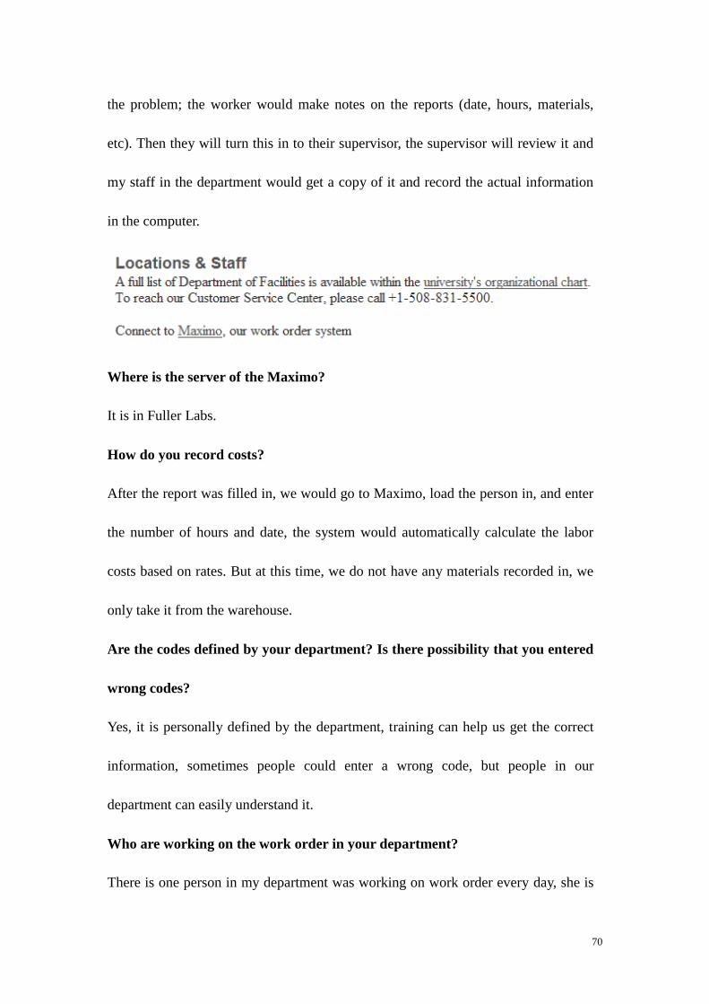
70
the problem; the worker would make notes on the reports (date, hours, materials,
etc). Then they will turn this in to their supervisor, the supervisor will review it and
my staff in the department would get a copy of it and record the actual information
in the computer.
Where is the server of the Maximo?
It is in Fuller Labs.
How do you record costs?
After the report was filled in, we would go to Maximo, load the person in, and enter
the number of hours and date, the system would automatically calculate the labor
costs based on rates. But at this time, we do not have any materials recorded in, we
only take it from the warehouse.
Are the codes defined by your department? Is there possibility that you entered
wrong codes?
Yes, it is personally defined by the department, training can help us get the correct
information, sometimes people could enter a wrong code, but people in our
department can easily understand it.
Who are working on the work order in your department?
There is one person in my department was working on work order every day, she is
71
an expert on that. And if there is more work than usual, another person would assist
work order. Also, there is a student, here, who is working at least 15 hours on work
order.
Is there any other reports?
Of course, Maximo can sort the information, for example, all the electrical work that
was done in Gateway. Similarly, we can find all the emergency work orders in
Gateway Park, or work orders in certain period.
What do you think that BIM can help on Maximo?
First, as I said, is the specific location, BIM can help us identify the problem easily
and fast.
The second would be asset management, like generators, boilers, and other big
equipments which needed to be maintained regularly. BIM can provide the detailed
information on it.

72
Interview with David Messier:
WPI Department of Facilities, 37 Lee Street; Worcester MA
March 2, 2010
What the model does not have but you need?
Chemical fume hood, for example, in Kaven, we have four, room 010 has two, room
007 has one, and room 002 has one. Those are important from the safety prospective,
which is when people are using chemicals; the chemical fume hood protects them.
And any other chemical buildings have chemical fume hoods.
Bio-safety cabinets (BSC), those are mostly in biology or biochemical labs, on main
campus you would fine ten in Goddard. At Gateway campus we have thirty. The
BSC are to protect people from injury by bio-chemicals and chemicals.
Emergency showers, wash units, smoke detector and sprinkler head, those which
would be other good features if you want to include, because we can actually see
them in the model and they also need annual maintenance and inspection.
What information in the Revit model would you be very interested?
Fire Extinguishers, Fire Alarms, Egress Pass, Exit Signs.
We can develop egress pass way from the building model. For instance, you can post
exit way of the Kaven Hall Computer Lab from the BIM model; that is one possible
use that I would see.
You can highlight fire extinguishers and fire alarms in case of emergency, people

73
can leave and know where the stuff is, and the people from the outside of the
building can easily indentify the stuff.
What kind of information do you have? How do you get it?
There is a plan room here; we have all the shop drawings and blueprints. If I need
some information, I go to the room and check, for instance, the Kaven Hall; I would
pull out the drawings as I can.
How do you keep the information?
It is kept on file, sometimes the documentation is requested by the city.

74
Appendix B - IU BIM Proficiency Matrix

75
Appendix C- BIM Proficiency Matrix
Submittal Firms (By 3/19/2010)
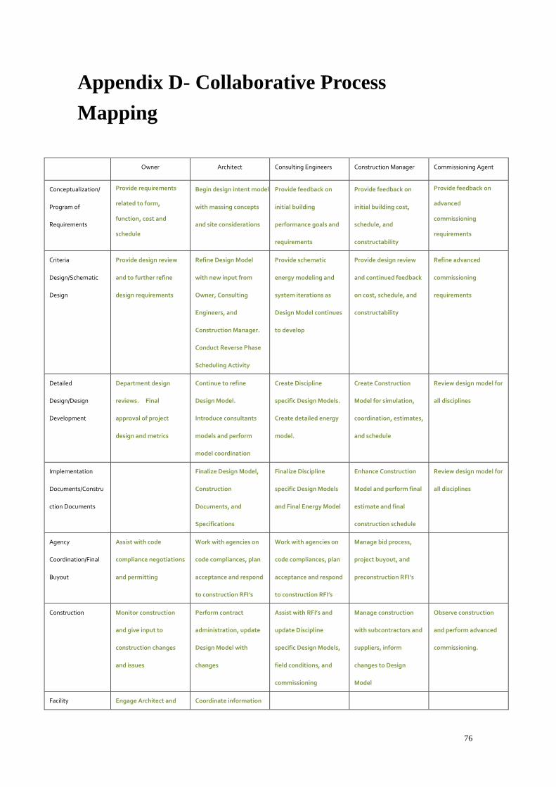
76
Appendix D- Collaborative Process
Mapping
Owner Architect Consulting Engineers Construction Manager Commissioning Agent
Conceptualization/
Program of
Requirements
Provide requirements
related to form,
function, cost and
schedule
Begin design intent model
with massing concepts
and site considerations
Provide feedback on
initial building
performance goals and
requirements
Provide feedback on
initial building cost,
schedule, and
constructability
Provide feedback on
advanced
commissioning
requirements
Criteria
Design/Schematic
Design
Provide design review
and to further refine
design requirements
Refine Design Model
with new input from
Owner, Consulting
Engineers, and
Construction Manager.
Conduct Reverse Phase
Scheduling Activity
Provide schematic
energy modeling and
system iterations as
Design Model continues
to develop
Provide design review
and continued feedback
on cost, schedule, and
constructability
Refine advanced
commissioning
requirements
Detailed
Design/Design
Development
Department design
reviews. Final
approval of project
design and metrics
Continue to refine
Design Model.
Introduce consultants
models and perform
model coordination
Create Discipline
specific Design Models.
Create detailed energy
model.
Create Construction
Model for simulation,
coordination, estimates,
and schedule
Review design model for
all disciplines
Implementation
Documents/Constru
ction Documents
Finalize Design Model,
Construction
Documents, and
Specifications
Finalize Discipline
specific Design Models
and Final Energy Model
Enhance Construction
Model and perform final
estimate and final
construction schedule
Review design model for
all disciplines
Agency
Coordination/Final
Buyout
Assist with code
compliance negotiations
and permitting
Work with agencies on
code compliances, plan
acceptance and respond
to construction RFI’s
Work with agencies on
code compliances, plan
acceptance and respond
to construction RFI’s
Manage bid process,
project buyout, and
preconstruction RFI’s
Construction Monitor construction
and give input to
construction changes
and issues
Perform contract
administration, update
Design Model with
changes
Assist with RFI’s and
update Discipline
specific Design Models,
field conditions, and
commissioning
Manage construction
with subcontractors and
suppliers, inform
changes to Design
Model
Observe construction
and perform advanced
commissioning.
Facility Engage Architect and Coordinate information

77
Management Facilities Group for
model turnover to staff.
exchange through
model to Facilities
Group

78
Appendix E - BIM Execution Planning
Process

79
Appendix F- Sample Room Schedule of
Kaven Hall model


![Development of BIM Execution Plan for BIM Model …...information system (GIS)-based FM system. Lin et al. [12] proposed a mobile automated BIM-based facility management (BIMFM) system](https://img.pdfslide.us/doc/110x75/5f5355582cc3004cb219b75f/development-of-bim-execution-plan-for-bim-model-information-system-gis-based.jpg)