Embed Size (px)
Citation preview
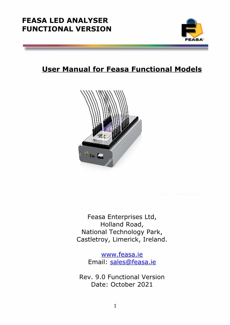
FEASA LED ANALYSERFUNCTIONAL VERSION
User Manual for Feasa Functional Models
Feasa Enterprises Ltd,Holland Road,
National Technology Park,Castletroy, Limerick, Ireland.
www.feasa.ieEmail: [email protected]
Rev. 9.0 Functional VersionDate: October 2021
1
FEASA LED ANALYSERFUNCTIONAL VERSION
About this Manual
Feasa operates a policy of continuous development. Feasa reserves the right to make changes and improvements to any of the products described in this document without prior notice.
Feasa reserves the right to revise this document or withdraw it at any time without prior notice.
This manual is written for models Feasa Functional Led Analysers. The model numbers are Feasa x-F, Feasa x-FB, Feasa x-LT (where x is the number of fibers either 3,5,6,10,20).
The Feasa 20-F is a standard 20 channel Analyser which will test up to 20 LED's while the Feasa 3-F is a standard 3 channel Analyser testing up to 3 LED's.
The Feasa 20-FB is a High Brightness 20 channel unit which will test up to 20 LED's while the Feasa 3-FB is a 3 channel High Brightness unit testing up to 3 LED's.
The Feasa 20-LT is a Life Tester 20 channel unit which will test up to 20 LED's in an oven while the Feasa 3-LT is a 3 channel Life Tester unit testing up to 3 LED's.
The interface on these units is USB or RS232-Serial.
© Copyright 2005-2021 by Feasa Enterprises Ltd. All rights reserved. No parts of thismanual may be reproduced or retransmitted in any form or means, electronic or mechanical, including photocopying, recording, or any other storage and retrieval system without prior permission in writing from Feasa Enterprises Ltd. Every effort has been made to ensure that the information in this manual is accurate. Feasa Enterprises Limited is not responsible for printing or clerical errors.
2
FEASA LED ANALYSERFUNCTIONAL VERSION
Table of ContentsIntroduction..........................................................................................................................................6IMPORTANT INFORMATION for Programmers...............................................................................7Colour and Saturation...........................................................................................................................8Intensity..............................................................................................................................................10Photopic Response..............................................................................................................................12White LED's.......................................................................................................................................13Setting Tolerance Limits for Colour and Intensity.............................................................................14Physical Layout..................................................................................................................................15USB Port Control...............................................................................................................................15Serial Port Control (RS232)...............................................................................................................16Trigger Port Control...........................................................................................................................17
Capture Commands........................................................................................................................18Capture Times Static Leds........................................................................................................18AUTO CAPTURE - Store LED Data .......................................................................................19MANUAL CAPTURE - Store LED Data for a specific range.................................................20Capture Times PWM Leds........................................................................................................21AUTO CAPTUREPWM - Store PWM LED Data...................................................................21MANUAL CAPTUREPWM - Store PWM LED Data for a specific Range............................22CAPTUREMULTI - Multiple Capture Command....................................................................23
Get Data Commands...........................................................................................................................24Under Range Condition............................................................................................................24Over Range Condition..............................................................................................................24Incorrect Capture Mode............................................................................................................24getRGBI## - Get RGB and Intensity for a LED.......................................................................25getHSI## - Get Hue, Saturation and Intensity..........................................................................26getxy## - Return the xy Chromaticity values...........................................................................27getxyi## - Return the xy Chromaticity & Relative Intensity values.........................................28getCIEXYZ## - Return the CIE 1931 XYZ Colour values......................................................29getUV## - Return the u'v' Chromaticity values........................................................................30getWAVELENGTH## - Get the Dominant Wavelength...........................................................31getWI## - Get the Dominant Wavelength & Intensity..............................................................32getWSI## - Get the Dominant Wavelength, Saturation & Intensity.........................................33getCCT## - Get the Correlated Colour Temperature................................................................34getINTENSITY## - Get the Relative Intensity.........................................................................35getABSINT@@ Get the Absolute Intensity Value of the Led under test.................................36getSIGNALLEVEL## - Get the Relative Intensity in a percentage of the Range....................37getFACTOR - Get the exposure Factor.....................................................................................38get7SEG# - Get the value of a 7 Segment Display...................................................................39getAUTOPWM - Get which Auto Capture Mode is active C or CPWM.................................40getintensitymode - Get which Intensity Mode is active Logarithmic or Linear.......................41getPHOTOPIC - Get which Photopic Mode is active...............................................................42getBAUD - Get the Baud Rate..................................................................................................43getHW - Get the Hardware Version..........................................................................................44
3
FEASA LED ANALYSERFUNCTIONAL VERSION
getSTATUS - Get a summary of the Led Analyser details........................................................45getSERIAL Get the Serial Number of the Analyser.................................................................46getVERSION - Get the Firmware Version................................................................................47EOT - End of Transmission Character......................................................................................48
General Set/ Put Commands ................................................................................................................49set/putFACTOR## - Set the Exposure Factor...........................................................................50set/putLOG - Change the Intensity Response of the Analyser to Logarithmic mode...............51set/putLIN - Change the Intensity response of the Analyser to Linear Mode...........................52setBAUD - Change the baud rate..............................................................................................53setAUTOPWM# - Change the Auto Capture mode to Auto PWM Mode................................54s et PHOTOPIC - Set which Photopic Mode you require ...........................................................55
User Calibration Mode.......................................................................................................................56Introduction:..............................................................................................................................56UserCal Manual Procedure:......................................................................................................57set/putINTGAIN - Set the Intensity GainFactor.......................................................................58getINTGAIN## - Get the Intensity Gain Factor.......................................................................59set/putXOFFSET##0.xxx - Set the x Chromaticity Offset.......................................................60set/putYOFFSET##0.xxx - Set the y Chromaticity Offset.......................................................61getXOFFSET## - Return the x Chromaticity offset.................................................................62getYOFFSET## - Return the y Chromaticity offset.................................................................63set/putWAVELENGTHOFFSET@@±## - Set the wavelength Offset....................................64getWAVELENGTHOFFSET@@ - Get the Dominant Wavelength Offset..............................65set/putABSINTMULT@@ - Set the Absolute Intensity Multiplier Factor..............................66getABSINTMULT@@ Get the Absolute Intensity Correction Factor of the Led under test...67setCALIBRATION## - Select the Calibration Set to use.........................................................68getCALIBRATIONset - Select the Calibration Set to use........................................................69ResetUserCal##- Reset the standard usercal setting to factory default.....................................70ResetRGBM - Reset the RGB usercal setting to factory default..............................................71SetCalibrationDateddmmyyyy - Set the user Cal Date.............................................................72getcalibrationdate Get the Calibration Date set by the user......................................................73
User Calibration for RGB Leds..........................................................................................................74External Trigger Mode.......................................................................................................................75
External Trigger Method:..........................................................................................................75Sequence Capture Mode:....................................................................................................................76
Introduction...............................................................................................................................76Capture Sequence Procedure:...................................................................................................77Set/Put SequenceMode# - Set sequence mode for Fibers.........................................................78Set/Put SequenceChannel@@ - Select sequence mode Fiber No............................................79Set/Put SequenceCapture##(#) - Set Sequence Capture Time..................................................80Set/Put SequenceWait##(#) - Set Sequence Wait Time............................................................81Set/Put SequenceNumber###(#) - Set the Number of Captures...............................................82Set/Put SequenceThreshold##### - Set the Intensity Threshold..............................................83Set/Put SequenceStartDelay### - Set delay in ms before sequencecapture starts....................84CaptureSequence - Start the Captures.......................................................................................85StoreSequence## - Store the sequence pattern..........................................................................86
4
FEASA LED ANALYSERFUNCTIONAL VERSION
IdentifySequence - Identify the current sequence pattern.........................................................87ResetSequence## - Reset a sequence pattern............................................................................88GetSequenceStored## - Get a sequence pattern........................................................................89GetSequence@@ - Get the binary sequence of Intensities.......................................................90GetSequenceTimes@@ - Get the Duty Cycle of the Sequence................................................91GetSequenceTimesAll - Get the Duty Cycle of the Sequence for all fibers.............................92GetFrequency## - Returns the frequency and duty cycle of Led..............................................93Get(Max/Min/Avg)Intensity## - Returns the Max/Min or Avg Intensity for the Seq Cap.......94GetFlicker## - Returns the Flicker Index and frequency after a Seq Cap................................95GetSequenceMode# - Get sequence mode for Fibers...............................................................96GetSequenceChannel - Select sequence mode Fiber No..........................................................97GetSequenceCapture - Get Sequence Capture Time.................................................................98GetSequenceWait - Get Sequence Wait Time...........................................................................99GetSequenceNumber - Get the Number of Captures..............................................................100GetSequenceThreshold - Get the Intensity Threshold............................................................101GetSequenceStartDelay - Get the delay before the CS command..........................................102
Daisy Chain Mode............................................................................................................................103Daisy Chain USB Wiring Method:.........................................................................................103Daisy Chain Serial RS232 Wiring Method:............................................................................104Daisy Chain Baudrate:............................................................................................................105Daisy Chain Identification:.....................................................................................................105BusFree - Deactivate any active Analysers.............................................................................106BusGet#### - Activate a LED Analyser.................................................................................107BusC - Initiate Capture for all LED Analyser's.......................................................................108BusC# - Initiate Capture for all LED Analyser's.....................................................................109BusC#pwm@@ - Store PWM LED Data for a specific Range..............................................110BusCE#### - Poll each LED Analyser to verify a capture is complete..................................111Ports Description and Wiring..................................................................................................112Daisy Chain Pinout..................................................................................................................113Step-by-Step method for Daisy Chaining...............................................................................114Example...................................................................................................................................116
Step-by-Step approach to Testing a LED.........................................................................................118Effect of PWM on Intensity Testing.................................................................................................119Step-by-Step approach to Testing a PWM LED...............................................................................120Testing a 7-Segment Display............................................................................................................121Command Summary:........................................................................................................................122Feasa Software..................................................................................................................................125
Documentation Folder.................................................................................................................125Feasa Terminal.............................................................................................................................125User Software..............................................................................................................................126Test Software...............................................................................................................................127User Calibration...........................................................................................................................128Programming...............................................................................................................................129
Specifications...................................................................................................................................130Warranty...........................................................................................................................................132
5
FEASA LED ANALYSERFUNCTIONAL VERSION
Introduction
The Feasa LED Analyser is an instrument that tests the HSI (Hue, Saturation, Intensity), RGB (Red, Green, Blue Colour content of a single LED), xyChromaticity, Dominant Wavelength and cct Colour temperature of Light Emitting Diodes (LEDs) in a test process. An individual LedAnalyser can have up to 20* 1mm flexible Fiber-Optic Light Guides which are mounted individually over the LEDs to be tested.
The Feasa Led Analyser can be trained to read other Led Parameters like Absolute Intensity and CIEXYZ in Luminous flux (lm), Luminous intensity (cd, mcd), Luminance (cd/m^2). It can also be trained to interpret the data from an RGB Led. These outputs will require the use of theFeasa Led Spectrometer.
Emitted Light from the LEDs is guided through these Fiber-Optic Light Guides to the Analyser where the raw data is stored. The raw data can then be read out of the Analyser through the Serial or USB Interfaces.
The USB Interface is 2.0 compatible.
The Serial Interface is a 3-Pin Connector with a 3 pin to 9 pin dtype cable (supplied) compatible with the RS-232C ports on machines.
All Colours are derived from the three primary Colours, Red, Green and Blue (RGB). The RGB values are used to identify different Colour LEDs.
The raw data from the Led under test is stored on the Led Analyser and output in differentformats as required through the USB and Serial interfaces.
* Other options include 3,5,6,10.
Back to Index
6

FEASA LED ANALYSERFUNCTIONAL VERSION
IMPORTANT INFORMATION for Programmers
set / put Commands
The Set / Put commands are used to adjust various settings in the LED Analyser such as Intensity, Exposure and offsets.
The Set commands are written to the on-board Flash.
These settings remain programmed in the Analyser even when the power is removed.The Led Analyser has a capacity limit of approximately 100,000 writes to the flash.
Use the Set command only to store relevant information on the Led Analyser. Please refrainfrom using Set commands in your high volume production programs as this constant writing tothe Flash will eventually corrupt the Led Analyser. Use the Put command instead.
The Put commands are written to the on-board RAM.
These settings will NOT remain programmed in the Analyser after the power is removed.
Use the Put command as often as you need in your program. This will prolong the life of theLed Analyser particularly in high volume testing environment.
Commands are transmitted and received using ASCII characters and are case-insensitive.All commands must be terminated with a <CR> or <LF> character.
Back to Index
7
FEASA LED ANALYSERFUNCTIONAL VERSION
Colour and Saturation
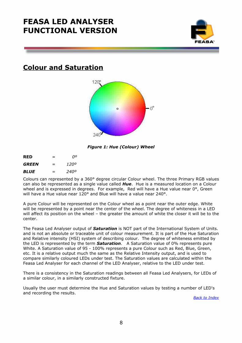
Figure 1: Hue (Colour) Wheel
RED = 0º
GREEN = 120º
BLUE = 240º
Colours can represented by a 360° degree circular Colour wheel. The three Primary RGB valuescan also be represented as a single value called Hue. Hue is a measured location on a Colour wheel and is expressed in degrees. For example, Red will have a Hue value near 0°, Green will have a Hue value near 120° and Blue will have a value near 240°.
A pure Colour will be represented on the Colour wheel as a point near the outer edge. White will be represented by a point near the center of the wheel. The degree of whiteness in a LED will affect its position on the wheel – the greater the amount of white the closer it will be to thecenter.
The Feasa Led Analyser output of Saturation is NOT part of the International System of Units.and is not an absolute or traceable unit of colour measurement. It is part of the Hue Saturationand Relative intensity (HSI) system of describing colour. The degree of whiteness emitted by the LED is represented by the term Saturation. A Saturation value of 0% represents pure White. A Saturation value of 95 - 100% represents a pure Colour such as Red, Blue, Green, etc. It is a relative output much the same as the Relative Intensity output, and is used to compare similarly coloured LEDs under test. The Saturation values are calculated within the Feasa Led Analyser for each channel of the LED Analyser, relative to the LED under test.
There is a consistency in the Saturation readings between all Feasa Led Analysers, for LEDs of a similar colour, in a similarly constructed fixture.
Usually the user must determine the Hue and Saturation values by testing a number of LED's and recording the results.
Back to Index
8
FEASA LED ANALYSERFUNCTIONAL VERSION
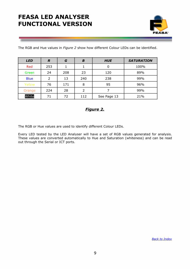
The RGB and Hue values in Figure 2 show how different Colour LEDs can be identified.
LED R G B HUE SATURATION
Red 253 1 1 0 100%
Green 24 208 23 120 89%
Blue 2 13 240 238 99%
Yellow 76 171 8 95 96%
Orange 224 28 2 7 99%
White 71 72 112 See Page 13 21%
Figure 2.
The RGB or Hue values are used to identify different Colour LEDs.
Every LED tested by the LED Analyser will have a set of RGB values generated for analysis.These values are converted automatically to Hue and Saturation (whiteness) and can be readout through the Serial or ICT ports.
Back to Index
9
FEASA LED ANALYSERFUNCTIONAL VERSION
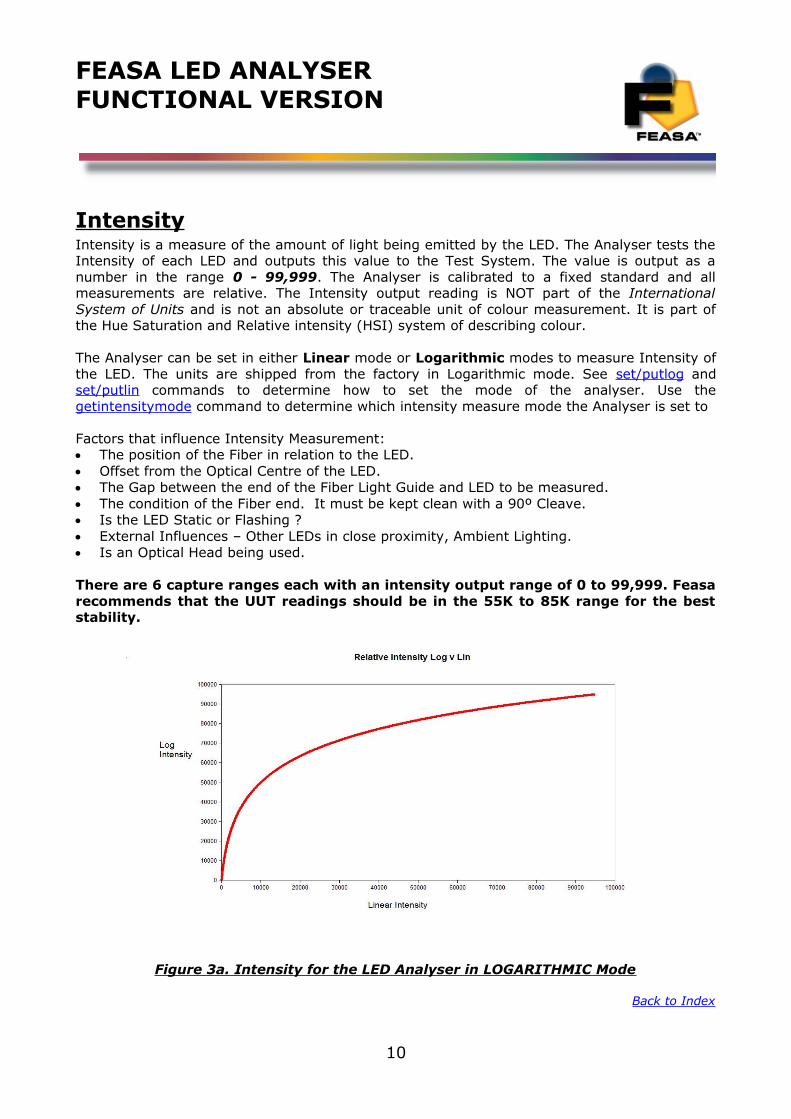
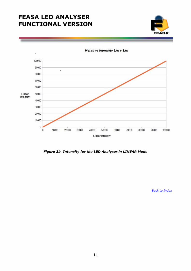
IntensityIntensity is a measure of the amount of light being emitted by the LED. The Analyser tests theIntensity of each LED and outputs this value to the Test System. The value is output as anumber in the range 0 - 99,999. The Analyser is calibrated to a fixed standard and allmeasurements are relative. The Intensity output reading is NOT part of the InternationalSystem of Units and is not an absolute or traceable unit of colour measurement. It is part ofthe Hue Saturation and Relative intensity (HSI) system of describing colour.
The Analyser can be set in either Linear mode or Logarithmic modes to measure Intensity ofthe LED. The units are shipped from the factory in Logarithmic mode. See set/ put log andset/ put lin commands to determine how to set the mode of the analyser. Use theget intensitymode command to determine which intensity measure mode the Analyser is set to
Factors that influence Intensity Measurement: The position of the Fiber in relation to the LED. Offset from the Optical Centre of the LED. The Gap between the end of the Fiber Light Guide and LED to be measured. The condition of the Fiber end. It must be kept clean with a 90º Cleave. Is the LED Static or Flashing ? External Influences – Other LEDs in close proximity, Ambient Lighting. Is an Optical Head being used.
There are 6 capture ranges each with an intensity output range of 0 to 99,999. Feasarecommends that the UUT readings should be in the 55K to 85K range for the beststability.
Figure 3a. Intensity for the LED Analyser in LOGARITHMIC Mode
Back to Index
10
FEASA LED ANALYSERFUNCTIONAL VERSION
Figure 3b. Intensity for the LED Analyser in LINEAR Mode
Back to Index
11
FEASA LED ANALYSERFUNCTIONAL VERSION
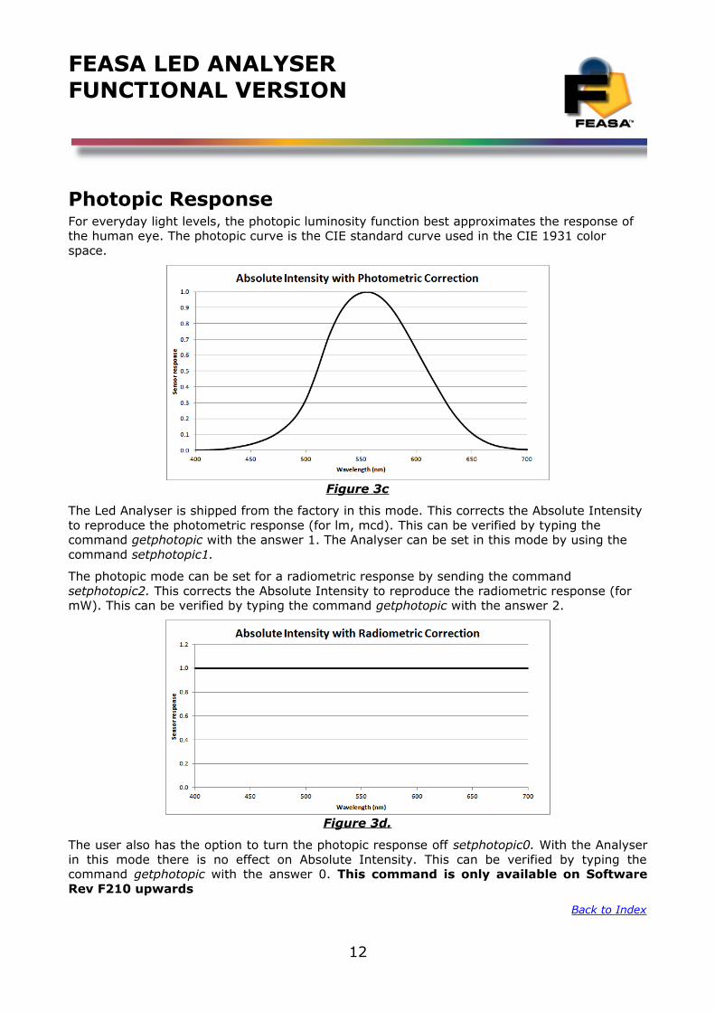
Photopic ResponseFor everyday light levels, the photopic luminosity function best approximates the response of the human eye. The photopic curve is the CIE standard curve used in the CIE 1931 color space.
Figure 3c
The Led Analyser is shipped from the factory in this mode. This corrects the Absolute Intensity to reproduce the photometric response (for lm, mcd). This can be verified by typing the command getphotopic with the answer 1. The Analyser can be set in this mode by using the command setphotopic1.
The photopic mode can be set for a radiometric response by sending the command setphotopic2. This corrects the Absolute Intensity to reproduce the radiometric response (for mW). This can be verified by typing the command getphotopic with the answer 2.
Figure 3d.
The user also has the option to turn the photopic response off setphotopic0. With the Analyserin this mode there is no effect on Absolute Intensity. This can be verified by typing thecommand getphotopic with the answer 0. This command is only available on SoftwareRev F210 upwards
Back to Index
12
FEASA LED ANALYSERFUNCTIONAL VERSION
White LED's
White LED's must be treated differently to coloured LED's when being tested. White is not a colour – it is a mix of all other colours. The three Primary colours Red, Green and Blue will be mixed in approximately equal proportions to display a White Colour. The Saturation values must be used when testing White LED's. The Saturation is a value between 0% and 100%. A value of 0% indicates a pure white and a value of 100% indicates a pure Colour.
In reality, the Saturation value of white LED's vary significantly with values of 30% being typical. Remember, the Saturation value is an indication of how white the LED is.The correct values must be determined experimentally with the particular LED's to be tested.
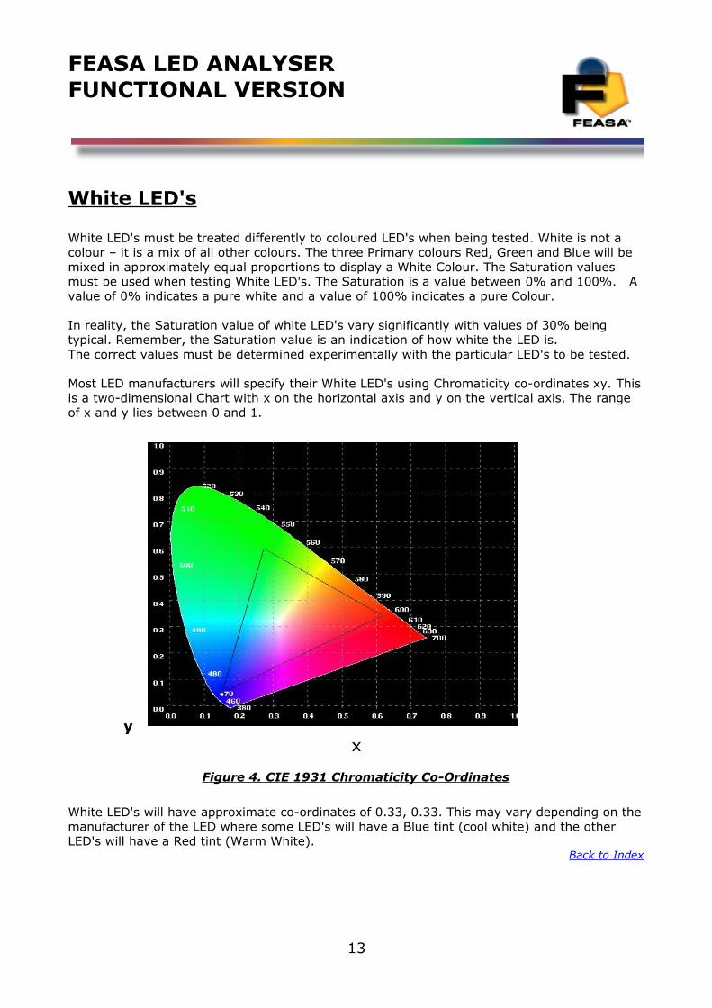
Most LED manufacturers will specify their White LED's using Chromaticity co-ordinates xy. Thisis a two-dimensional Chart with x on the horizontal axis and y on the vertical axis. The range of x and y lies between 0 and 1.
y x
Figure 4. CIE 1931 Chromaticity Co-Ordinates
White LED's will have approximate co-ordinates of 0.33, 0.33. This may vary depending on themanufacturer of the LED where some LED's will have a Blue tint (cool white) and the other LED's will have a Red tint (Warm White).
Back to Index
13
FEASA LED ANALYSERFUNCTIONAL VERSION
Setting Tolerance Limits for Colour and Intensity
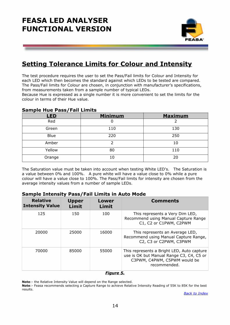
The test procedure requires the user to set the Pass/Fail limits for Colour and Intensity for each LED which then becomes the standard against which LEDs to be tested are compared.The Pass/Fail limits for Colour are chosen, in conjunction with manufacturer’s specifications, from measurements taken from a sample number of typical LEDs.Because Hue is expressed as a single number it is more convenient to set the limits for the colour in terms of their Hue value.
Sample Hue Pass/Fail LimitsLED Minimum MaximumRed 0 2
Green 110 130
Blue 220 250
Amber 2 10
Yellow 80 110
Orange 10 20
The Saturation value must be taken into account when testing White LED's. The Saturation is a value between 0% and 100%. A pure white will have a value close to 0% while a pure colour will have a value close to 100%. The Pass/Fail limits for intensity are chosen from the average intensity values from a number of sample LEDs.
Sample Intensity Pass/Fail Limits in Auto ModeRelative
Intensity ValueUpperLimit
LowerLimit
Comments
125 150 100 This represents a Very Dim LED,Recommend using Manual Capture Range
C1, C2 or C1PWM, C2PWM
20000 25000 16000 This represents an Average LED,Recommend using Manual Capture Range,
C2, C3 or C2PWM, C3PWM
70000 85000 55000 This represents a Bright LED, Auto captureuse is OK but Manual Range C3, C4, C5 or
C3PWM, C4PWM, C5PWM would berecommended.
Figure 5.
Note:- the Relative Intensity Value will depend on the Range selected.Note:- Feasa recommends selecting a Capture Range to achieve Relative Intensity Reading of 55K to 85K for the best results.
Back to Index
14
FEASA LED ANALYSERFUNCTIONAL VERSION
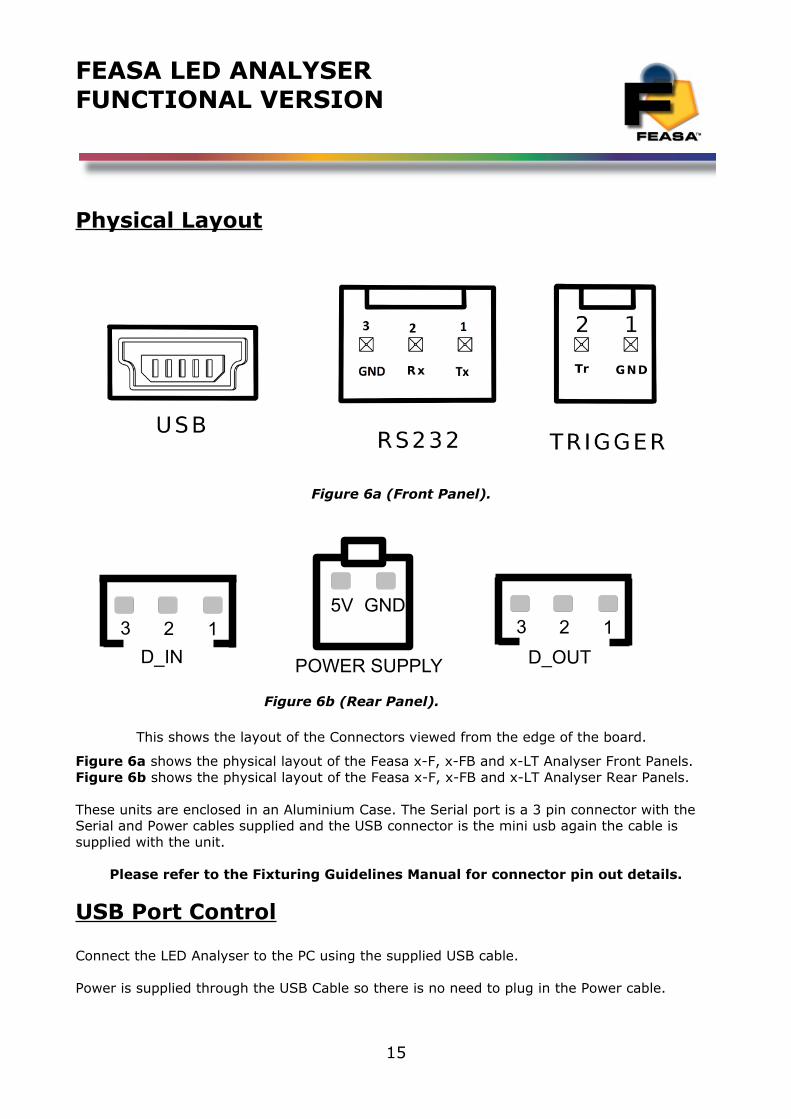
Physical Layout
Figure 6a (Front Panel).
Figure 6b (Rear Panel).
This shows the layout of the Connectors viewed from the edge of the board.
Figure 6a shows the physical layout of the Feasa x-F, x-FB and x-LT Analyser Front Panels.Figure 6b shows the physical layout of the Feasa x-F, x-FB and x-LT Analyser Rear Panels.
These units are enclosed in an Aluminium Case. The Serial port is a 3 pin connector with the Serial and Power cables supplied and the USB connector is the mini usb again the cable is supplied with the unit.
Please refer to the Fixturing Guidelines Manual for connector pin out details.
USB Port Control
Connect the LED Analyser to the PC using the supplied USB cable.
Power is supplied through the USB Cable so there is no need to plug in the Power cable.
15
123
D_IN
123
D_OUT
GND5V
POWER SUPPLY

FEASA LED ANALYSERFUNCTIONAL VERSION
The installed Software Driver will configure the USB Port automatically.
The USB Port is configured as a Virtual Com Port and will be designated a name such as COM5,COM6, etc.
Back to Index
16
FEASA LED ANALYSERFUNCTIONAL VERSION
Serial Port Control (RS232)
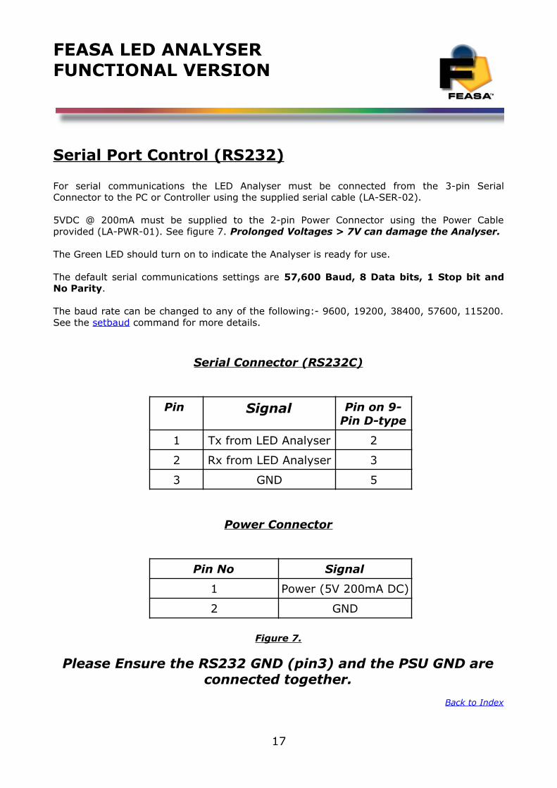
For serial communications the LED Analyser must be connected from the 3-pin SerialConnector to the PC or Controller using the supplied serial cable (LA-SER-02).
5VDC @ 200mA must be supplied to the 2-pin Power Connector using the Power Cableprovided (LA-PWR-01). See figure 7. Prolonged Voltages > 7V can damage the Analyser.
The Green LED should turn on to indicate the Analyser is ready for use.
The default serial communications settings are 57,600 Baud, 8 Data bits, 1 Stop bit andNo Parity.
The baud rate can be changed to any of the following:- 9600, 19200, 38400, 57600, 115200.See the setbaud command for more details.
Serial Connector (RS232C)
Pin Signal Pin on 9-Pin D-type
1 Tx from LED Analyser 2
2 Rx from LED Analyser 3
3 GND 5
Power Connector
Pin No Signal
1 Power (5V 200mA DC)
2 GND
Figure 7.
Please Ensure the RS232 GND (pin3) and the PSU GND areconnected together.
Back to Index
17
FEASA LED ANALYSERFUNCTIONAL VERSION
Trigger Port Control
The Feasa Led Analyser includes a Trigger function that allows an external signal to trigger a capture. For Trigger Function to operate the LED Analyser must be connected from the 2-pin Trigger Connector to the PC or Controller using the supplied serial cable (LA-TR-01). The Trigger function must first be enabled by sending commands to the Led Analyser. The capture is triggered by a high-to-low transition on the Trigger Pin. See the External Trigger Mode section of this manual for the programming details.
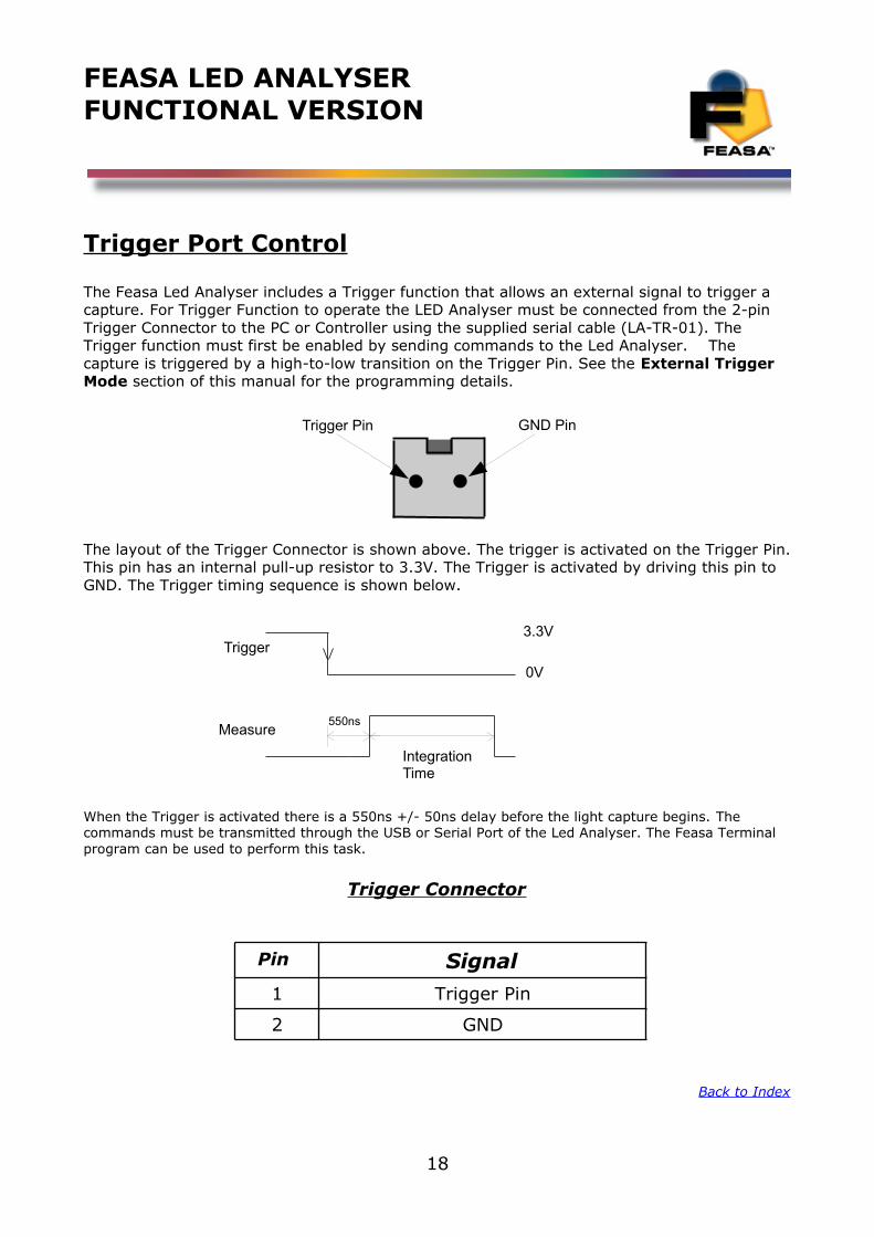
The layout of the Trigger Connector is shown above. The trigger is activated on the Trigger Pin.This pin has an internal pull-up resistor to 3.3V. The Trigger is activated by driving this pin to GND. The Trigger timing sequence is shown below.
When the Trigger is activated there is a 550ns +/- 50ns delay before the light capture begins. The commands must be transmitted through the USB or Serial Port of the Led Analyser. The Feasa Terminal program can be used to perform this task.
Trigger Connector
Pin Signal
1 Trigger Pin
2 GND
Back to Index
18
Trigger Pin GND Pin
Trigger
Measure550ns
3.3V
0V
IntegrationTime
FEASA LED ANALYSERFUNCTIONAL VERSION
Capture Commands
The Capture commands are used to capture the parameters (colour, saturation, intensity, xy, uv, wavelength, cct) of the LED's to be tested and store the results in the memory of the Analyser.
These results can be read out later using the GET DATA commands.
Commands are transmitted and received using ASCII characters and are NOT case-sensitive.All commands must be terminated with a <CR> or <LF> character. All responses from theLed Analyser are also terminated with <CR> <LF>
The Terminal Program supplied on the CD is used to send/receive commands to/from the Analyser. This program is also available as a drop down box in the User program and the TestSoftware program.
The Feasa LED Analyser USER Program is a graphical tool that can be used to send commands and receive results from the Analyser. It allows one LED to be tested at a time. This Program also allows a Terminal Window to be opened so that the User can type the commands directly and send them to the Analyser. The responses from the Analyser can be observed in the Window.
The Feasa LED Analyser TEST Program allows the User to test all the LED's together. Pass and Fail limits can be set and results can be printed and logged.
Alternately, the User may generate a customised Program that sends commands and receives data through the virtual USB Com Port or RS232 Serial Port.
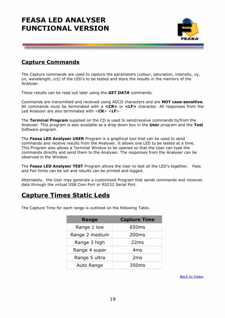
Capture Times Static Leds
The Capture Time for each range is outlined on the following Table.
Range Capture Time
Range 1 low 650ms
Range 2 medium 200ms
Range 3 high 22ms
Range 4 super 4ms
Range 5 ultra 2ms
Auto Range 350ms
Back to Index
19
FEASA LED ANALYSERFUNCTIONAL VERSION
Capture Mode
AUTO CAPTURE - Store LED Data
Transmit Receive
capturec
OKOK
Description
This Auto Range Capture instructs the LED Analyser to capture and store the data of all theLED's positioned under the fibers. The Analyser automatically determines the correct settingsto capture the LED data based on the Intensity. In the case of a 20 channel unit the data forall 20 LED's are captured simultaneously and stored in internal memory of the LED Analyser.The data is stored until the power is removed or another capture command is issued. Whencompleted the Analyser will transmit the character OK on the receive line to the transmittingdevice (i.e. the PC).
This command uses a wide Intensity range to be able to test dim and bright LED'ssimultaneously. However, if the LED's to be tested are of similar Intensity then better resultswill be obtained by using the Capture # command described on the next page.
Example:
The PC transmits capture to the LED Analyser and the LED Analyser sends OK to the PC toacknowledge that the command is completed.
captureOK
or
COK
Back to Index
20
FEASA LED ANALYSERFUNCTIONAL VERSION
Capture Mode
MANUAL CAPTURE - Store LED Data for a specific range
Transmit Receive
capture#c#
OKOK
Where:# represents the ranges 1, 2, 3, 4, 5.
The LED brightness level for each range is as follows:-Range 1 = LowRange 2 = MediumRange 3 = HighRange 4 = SuperRange 5 = Ultra
DescriptionThis command uses a pre-selected exposure time designated Range1, Range2 etc. For lowlight or dim LED's use Range 1 and for brighter LED's use higher ranges. The higher rangeslead to faster test times because the exposure time is shorter.This command instructs the LED Analyser to read and store the Colour and Intensity of all theLED's positioned under the fibers using a fixed range. The range setting must be specified. The data is stored until the power is removed or anothercapture# command is issued. When completed the Analyser will transmit the character OKon the receive line to the transmitting device (i.e. the PC).
Example:The PC transmits capture# to the LED Analyser and the LED Analyser sends OK to the PC toacknowledge that the command is completed.capture2OK
or
c2OK
There are 5 manual capture ranges each with an intensity output range of 0 to99,999. Feasa recommends that the UUT readings should be in the 55K to 85K rangefor the best stability.
Back to Index
21
FEASA LED ANALYSERFUNCTIONAL VERSION
Capture Mode
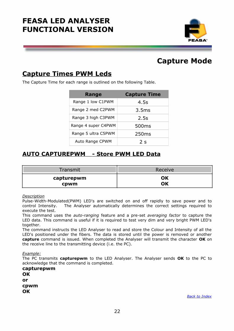
Capture Times PWM LedsThe Capture Time for each range is outlined on the following Table.
Range Capture TimeRange 1 low C1PWM 4.5sRange 2 med C2PWM 3.5msRange 3 high C3PWM 2.5sRange 4 super C4PWM 500msRange 5 ultra C5PWM 250ms
Auto Range CPWM 2 s
AUTO CAPTUREPWM - Store PWM LED Data
Transmit Receive
capturepwmcpwm
OKOK
DescriptionPulse-Width-Modulated(PWM) LED's are switched on and off rapidly to save power and tocontrol Intensity. The Analyser automatically determines the correct settings required toexecute the test.This command uses the auto-ranging feature and a pre-set averaging factor to capture theLED data. This command is useful if it is required to test very dim and very bright PWM LED'stogether. The command instructs the LED Analyser to read and store the Colour and Intensity of all theLED's positioned under the fibers. The data is stored until the power is removed or anothercapture command is issued. When completed the Analyser will transmit the character OK onthe receive line to the transmitting device (i.e. the PC).
Example:The PC transmits capturepwm to the LED Analyser. The Analyser sends OK to the PC toacknowledge that the command is completed.capturepwmOKorcpwmOK
Back to Index
22
FEASA LED ANALYSERFUNCTIONAL VERSION
Capture ModeMANUAL CAPTUREPWM - Store PWM LED Data for a specific Range
Transmit Receive
capture#pwm@@capture#pwm
OKOK
Where:
# represents the exposure Range 1 – 5.@@ represents an averaging factor in the range 1 - 15.@@ If the @@ digits are omitted then a default setting of 07 is used.
Description
This command allows the User to specify the exposure range # and an averaging factor @@when testing PWM LED's. Select the exposure range # (1-5) to match the Intensity of theLED's. The Analyser tests these LED's by taking a number of readings and averaging theresults. A larger Averaging factor will lead to more stable results but increased Test Times.The averaging factor @@ is a number in the range 1-15. If this number is omitted from thecommand the default value is 07.
This command instructs the LED Analyser to read and store the Colour and Intensity of all theLED's positioned under the fibers. The data is stored until the power is removed or anothercapture command is issued. When completed the Analyser will transmit the character OK onthe receive line to the transmitting device (i.e. the PC).
capture1pwm10OK
or
c1pwm10OK
There are 5 manual capture ranges each with an intensity output range of 0 to99,999. Feasa recommends that the UUT readings should be in the 55K to 85K rangefor the best stability.
Back to Index
23
FEASA LED ANALYSERFUNCTIONAL VERSION
Capture Mode
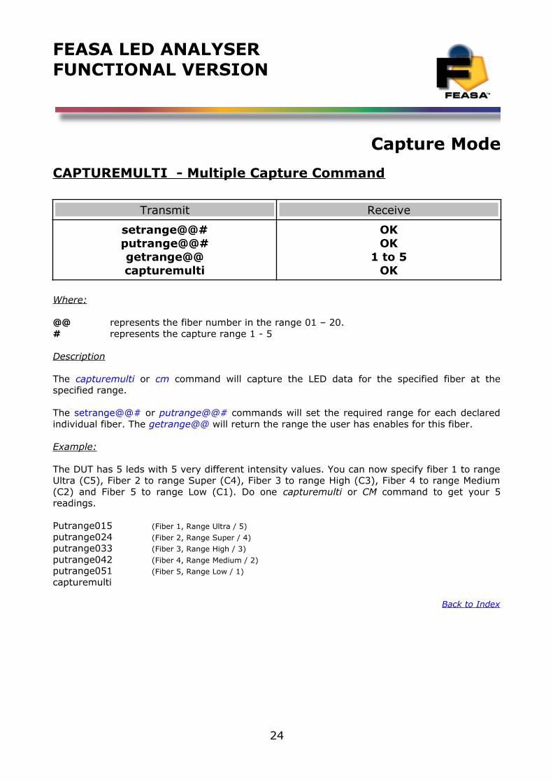
CAPTUREMULTI - Multiple Capture Command
Transmit Receive
setrange@@#putrange@@#getrange@@capturemulti
OKOK
1 to 5OK
Where:
@@ represents the fiber number in the range 01 – 20.# represents the capture range 1 - 5
Description
The capturemulti or cm command will capture the LED data for the specified fiber at thespecified range.
The setrange@@# or putrange@@# commands will set the required range for each declaredindividual fiber. The getrange@@ will return the range the user has enables for this fiber.
Example:
The DUT has 5 leds with 5 very different intensity values. You can now specify fiber 1 to rangeUltra (C5), Fiber 2 to range Super (C4), Fiber 3 to range High (C3), Fiber 4 to range Medium(C2) and Fiber 5 to range Low (C1). Do one capturemulti or CM command to get your 5readings.
Putrange015 (Fiber 1, Range Ultra / 5)
putrange024 (Fiber 2, Range Super / 4)putrange033 (Fiber 3, Range High / 3)
putrange042 (Fiber 4, Range Medium / 2)putrange051 (Fiber 5, Range Low / 1)
capturemulti
Back to Index
24
FEASA LED ANALYSERFUNCTIONAL VERSION
Get Data Commands
The get data commands are used to read out the Colour, Saturation and Intensity data stored by the capture commands.
The data from the last capture command remains in memory until a new capture command isissued or the power is removed from the Analyser.
Commands are transmitted and received using ASCII characters and are NOT case-sensitive.All commands must be terminated with a <CR> or <LF> character.
Under Range ConditionAn under range condition will occur when insufficient light from the LED reaches the sensor for the range selected. This will be indicated by 999.99 999 00000 for HSI, 000 000 000 00000 for RGBI and 0.0000 0.0000 for xy and uv.
If this condition occurs select the next lower range and test again.
Over Range ConditionAn over range condition will occur when too much light from the LED reaches the sensor for the range selected by the switch. This will be indicated by 999.99 999 99999 for HSI, 255 255 255 99999 for RGBI and 0.0000 0.0000 for xy and uv.
If this condition occurs select the next higher range and test again.
Incorrect Capture ModeAn incorrect capture mode condition will occur when a blinking (pwm) light from the LED reaches the sensor when the Autorange C capture is selected. This will be indicated by XXX.XX XXX XXXXX for HSI, XXX XXX XXX XXXXX for RGBI and X.XXXX X.XXXX for xy and uv.
The manual Capture Ranges C1 – C5 are unaffected by this.
If this condition occurs in Software Rev F201 – F206 use the CPWM command instead of the Capture command. For software Rev F207 upwards you can set the capture command to mimic the cpwm command by typing setautopwm1. This can be verified using the getstatus or getautopwm commands. To turn this function off type the command setautopwm0.
Back to Index
25
FEASA LED ANALYSERFUNCTIONAL VERSION
Get Data Mode
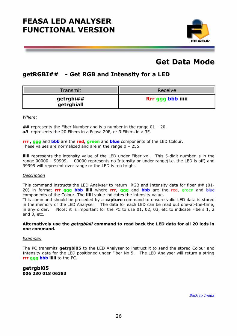
getRGBI## - Get RGB and Intensity for a LED
Transmit Receive
getrgbi##getrgbiall
Rrr ggg bbb iiiii
Where:
## represents the Fiber Number and is a number in the range 01 – 20.all represents the 20 Fibers in a Feasa 20F, or 3 Fibers in a 3F.
rrr , ggg and bbb are the red, green and blue components of the LED Colour.These values are normalized and are in the range 0 – 255.
iiiii represents the intensity value of the LED under Fiber xx. This 5-digit number is in therange 00000 – 99999. 00000 represents no Intensity or under range(i.e. the LED is off) and99999 will represent over range or the LED is too bright.
Description
This command instructs the LED Analyser to return RGB and Intensity data for fiber ## (01-20) in format rrr ggg bbb iiiii where rrr, ggg and bbb are the red, green and bluecomponents of the Colour. The iiiii value indicates the intensity value.This command should be preceded by a capture command to ensure valid LED data is storedin the memory of the LED Analyser. The data for each LED can be read out one-at-the-time,in any order. Note: it is important for the PC to use 01, 02, 03, etc to indicate Fibers 1, 2and 3, etc.
Alternatively use the getrgbiall command to read back the LED data for all 20 leds inone command.
Example:
The PC transmits getrgbi05 to the LED Analyser to instruct it to send the stored Colour andIntensity data for the LED positioned under Fiber No 5. The LED Analyser will return a stringrrr ggg bbb iiiii to the PC.
getrgbi05006 230 018 06383
Back to Index
26
FEASA LED ANALYSERFUNCTIONAL VERSION
Get Data Mode
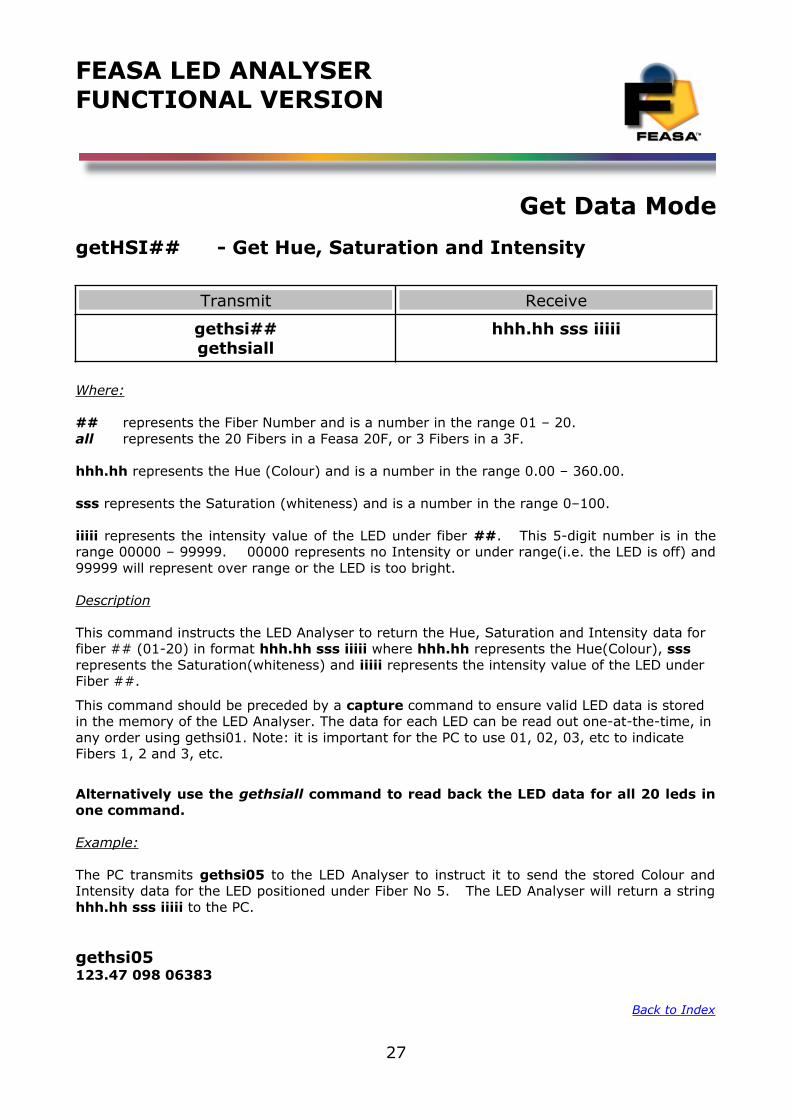
getHSI## - Get Hue, Saturation and Intensity
Transmit Receive
gethsi##gethsiall
hhh.hh sss iiiii
Where:
## represents the Fiber Number and is a number in the range 01 – 20.all represents the 20 Fibers in a Feasa 20F, or 3 Fibers in a 3F.
hhh.hh represents the Hue (Colour) and is a number in the range 0.00 – 360.00.
sss represents the Saturation (whiteness) and is a number in the range 0–100.
iiiii represents the intensity value of the LED under fiber ##. This 5-digit number is in therange 00000 – 99999. 00000 represents no Intensity or under range(i.e. the LED is off) and99999 will represent over range or the LED is too bright.
Description
This command instructs the LED Analyser to return the Hue, Saturation and Intensity data for fiber ## (01-20) in format hhh.hh sss iiiii where hhh.hh represents the Hue(Colour), sss represents the Saturation(whiteness) and iiiii represents the intensity value of the LED under Fiber ##.
This command should be preceded by a capture command to ensure valid LED data is stored in the memory of the LED Analyser. The data for each LED can be read out one-at-the-time, in any order using gethsi01. Note: it is important for the PC to use 01, 02, 03, etc to indicate Fibers 1, 2 and 3, etc.
Alternatively use the gethsiall command to read back the LED data for all 20 leds inone command.
Example:
The PC transmits gethsi05 to the LED Analyser to instruct it to send the stored Colour andIntensity data for the LED positioned under Fiber No 5. The LED Analyser will return a stringhhh.hh sss iiiii to the PC.
gethsi05123.47 098 06383
Back to Index
27
FEASA LED ANALYSERFUNCTIONAL VERSION
Get Data Mode
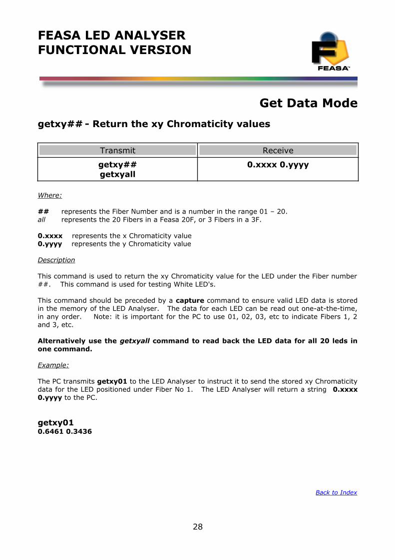
getxy## - Return the xy Chromaticity values
Transmit Receive
getxy##getxyall
0.xxxx 0.yyyy
Where:
## represents the Fiber Number and is a number in the range 01 – 20.all represents the 20 Fibers in a Feasa 20F, or 3 Fibers in a 3F.
0.xxxx represents the x Chromaticity value0.yyyy represents the y Chromaticity value
Description
This command is used to return the xy Chromaticity value for the LED under the Fiber number##. This command is used for testing White LED's.
This command should be preceded by a capture command to ensure valid LED data is storedin the memory of the LED Analyser. The data for each LED can be read out one-at-the-time,in any order. Note: it is important for the PC to use 01, 02, 03, etc to indicate Fibers 1, 2and 3, etc.
Alternatively use the getxyall command to read back the LED data for all 20 leds inone command.
Example:
The PC transmits getxy01 to the LED Analyser to instruct it to send the stored xy Chromaticitydata for the LED positioned under Fiber No 1. The LED Analyser will return a string 0.xxxx0.yyyy to the PC.
getxy010.6461 0.3436
Back to Index
28
FEASA LED ANALYSERFUNCTIONAL VERSION
Get Data Mode
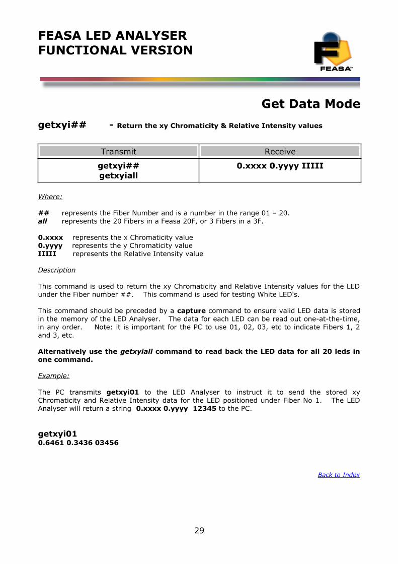
getxyi## - Return the xy Chromaticity & Relative Intensity values
Transmit Receive
getxyi##getxyiall
0.xxxx 0.yyyy IIIII
Where:
## represents the Fiber Number and is a number in the range 01 – 20.all represents the 20 Fibers in a Feasa 20F, or 3 Fibers in a 3F.
0.xxxx represents the x Chromaticity value0.yyyy represents the y Chromaticity valueIIIII represents the Relative Intensity value
Description
This command is used to return the xy Chromaticity and Relative Intensity values for the LEDunder the Fiber number ##. This command is used for testing White LED's.
This command should be preceded by a capture command to ensure valid LED data is storedin the memory of the LED Analyser. The data for each LED can be read out one-at-the-time,in any order. Note: it is important for the PC to use 01, 02, 03, etc to indicate Fibers 1, 2and 3, etc.
Alternatively use the getxyiall command to read back the LED data for all 20 leds inone command.
Example:
The PC transmits getxyi01 to the LED Analyser to instruct it to send the stored xyChromaticity and Relative Intensity data for the LED positioned under Fiber No 1. The LEDAnalyser will return a string 0.xxxx 0.yyyy 12345 to the PC.
getxyi010.6461 0.3436 03456
Back to Inde x
29
FEASA LED ANALYSERFUNCTIONAL VERSION
Get Data Mode
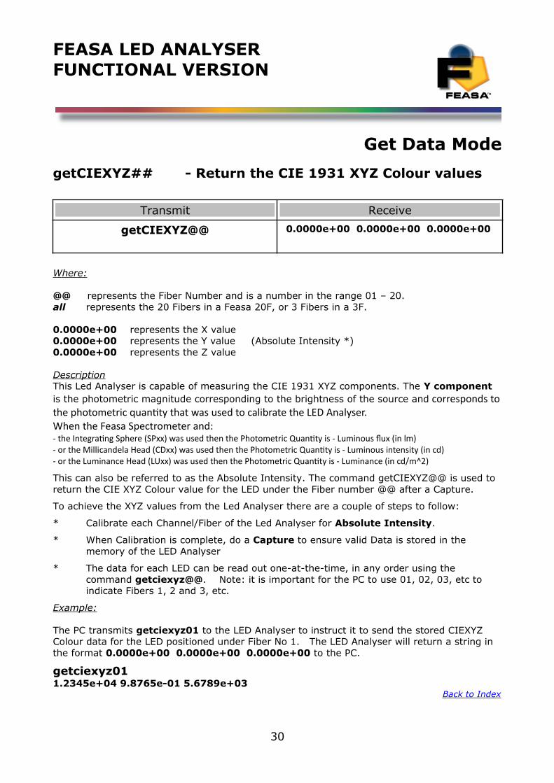
getCIEXYZ## - Return the CIE 1931 XYZ Colour values
Transmit Receive
getCIEXYZ@@ 0.0000e+00 0.0000e+00 0.0000e+00
Where:
@@ represents the Fiber Number and is a number in the range 01 – 20.all represents the 20 Fibers in a Feasa 20F, or 3 Fibers in a 3F.
0.0000e+00 represents the X value0.0000e+00 represents the Y value (Absolute Intensity *)0.0000e+00 represents the Z value
DescriptionThis Led Analyser is capable of measuring the CIE 1931 XYZ components. The Y component is the photometric magnitude corresponding to the brightness of the source and corresponds tothe photometric quantity that was used to calibrate the LED Analyser.When the Feasa Spectrometer and:- the Integrating Sphere (SPxx) was used then the Photometric Quantity is - Luminous flux (in lm)- or the Millicandela Head (CDxx) was used then the Photometric Quantity is - Luminous intensity (in cd) - or the Luminance Head (LUxx) was used then the Photometric Quantity is - Luminance (in cd/m^2)
This can also be referred to as the Absolute Intensity. The command getCIEXYZ@@ is used to return the CIE XYZ Colour value for the LED under the Fiber number @@ after a Capture.
To achieve the XYZ values from the Led Analyser there are a couple of steps to follow:
* Calibrate each Channel/Fiber of the Led Analyser for Absolute Intensity.
* When Calibration is complete, do a Capture to ensure valid Data is stored in the memory of the LED Analyser
* The data for each LED can be read out one-at-the-time, in any order using the command getciexyz@@. Note: it is important for the PC to use 01, 02, 03, etc to indicate Fibers 1, 2 and 3, etc.
Example:
The PC transmits getciexyz01 to the LED Analyser to instruct it to send the stored CIEXYZ Colour data for the LED positioned under Fiber No 1. The LED Analyser will return a string in the format 0.0000e+00 0.0000e+00 0.0000e+00 to the PC.
getciexyz011.2345e+04 9.8765e-01 5.6789e+03
Back to Inde x
30
FEASA LED ANALYSERFUNCTIONAL VERSION
Get Data Mode
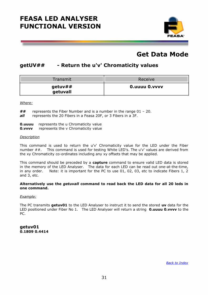
getUV## - Return the u'v' Chromaticity values
Transmit Receive
getuv##getuvall
0.uuuu 0.vvvv
Where:
## represents the Fiber Number and is a number in the range 01 – 20.all represents the 20 Fibers in a Feasa 20F, or 3 Fibers in a 3F.
0.uuuu represents the u Chromaticity value0.vvvv represents the v Chromaticity value
Description
This command is used to return the u'v' Chromaticity value for the LED under the Fibernumber ##. This command is used for testing White LED's. The u'v' values are derived fromthe xy Chromaticity co-ordinates including any xy offsets that may be applied.
This command should be preceded by a capture command to ensure valid LED data is storedin the memory of the LED Analyser. The data for each LED can be read out one-at-the-time,in any order. Note: it is important for the PC to use 01, 02, 03, etc to indicate Fibers 1, 2and 3, etc.
Alternatively use the getuvall command to read back the LED data for all 20 leds inone command.
Example:
The PC transmits getuv01 to the LED Analyser to instruct it to send the stored uv data for theLED positioned under Fiber No 1. The LED Analyser will return a string 0.uuuu 0.vvvv to thePC.
getuv010.1809 0.4414
Back to Index
31
FEASA LED ANALYSERFUNCTIONAL VERSION
Get Data Mode
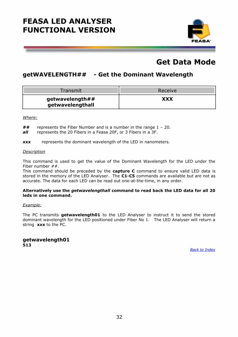
getWAVELENGTH## - Get the Dominant Wavelength
Transmit Receive
getwavelength##getwavelengthall
XXX
Where:
## represents the Fiber Number and is a number in the range 1 – 20.all represents the 20 Fibers in a Feasa 20F, or 3 Fibers in a 3F.
xxx represents the dominant wavelength of the LED in nanometers.
Description
This command is used to get the value of the Dominant Wavelength for the LED under theFiber number ##. This command should be preceded by the capture C command to ensure valid LED data isstored in the memory of the LED Analyser. The C1-C5 commands are available but are not asaccurate. The data for each LED can be read out one-at-the-time, in any order.
Alternatively use the getwavelengthall command to read back the LED data for all 20leds in one command.
Example:
The PC transmits getwavelength01 to the LED Analyser to instruct it to send the storeddominant wavelength for the LED positioned under Fiber No 1. The LED Analyser will return astring xxx to the PC.
getwavelength01513
Back to Index
32
FEASA LED ANALYSERFUNCTIONAL VERSION
Get Data Mode
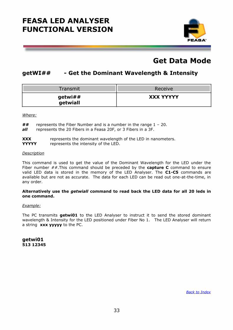
getWI## - Get the Dominant Wavelength & Intensity
Transmit Receive
getwi##getwiall
XXX YYYYY
Where:
## represents the Fiber Number and is a number in the range 1 – 20.all represents the 20 Fibers in a Feasa 20F, or 3 Fibers in a 3F.
XXX represents the dominant wavelength of the LED in nanometers.YYYYY represents the intensity of the LED.
Description
This command is used to get the value of the Dominant Wavelength for the LED under theFiber number ##.This command should be preceded by the capture C command to ensurevalid LED data is stored in the memory of the LED Analyser. The C1-C5 commands areavailable but are not as accurate. The data for each LED can be read out one-at-the-time, inany order.
Alternatively use the getwiall command to read back the LED data for all 20 leds inone command.
Example:
The PC transmits getwi01 to the LED Analyser to instruct it to send the stored dominantwavelength & Intensity for the LED positioned under Fiber No 1. The LED Analyser will returna string xxx yyyyy to the PC.
getwi01513 12345
Back to Index
33
FEASA LED ANALYSERFUNCTIONAL VERSION
Get Data Mode
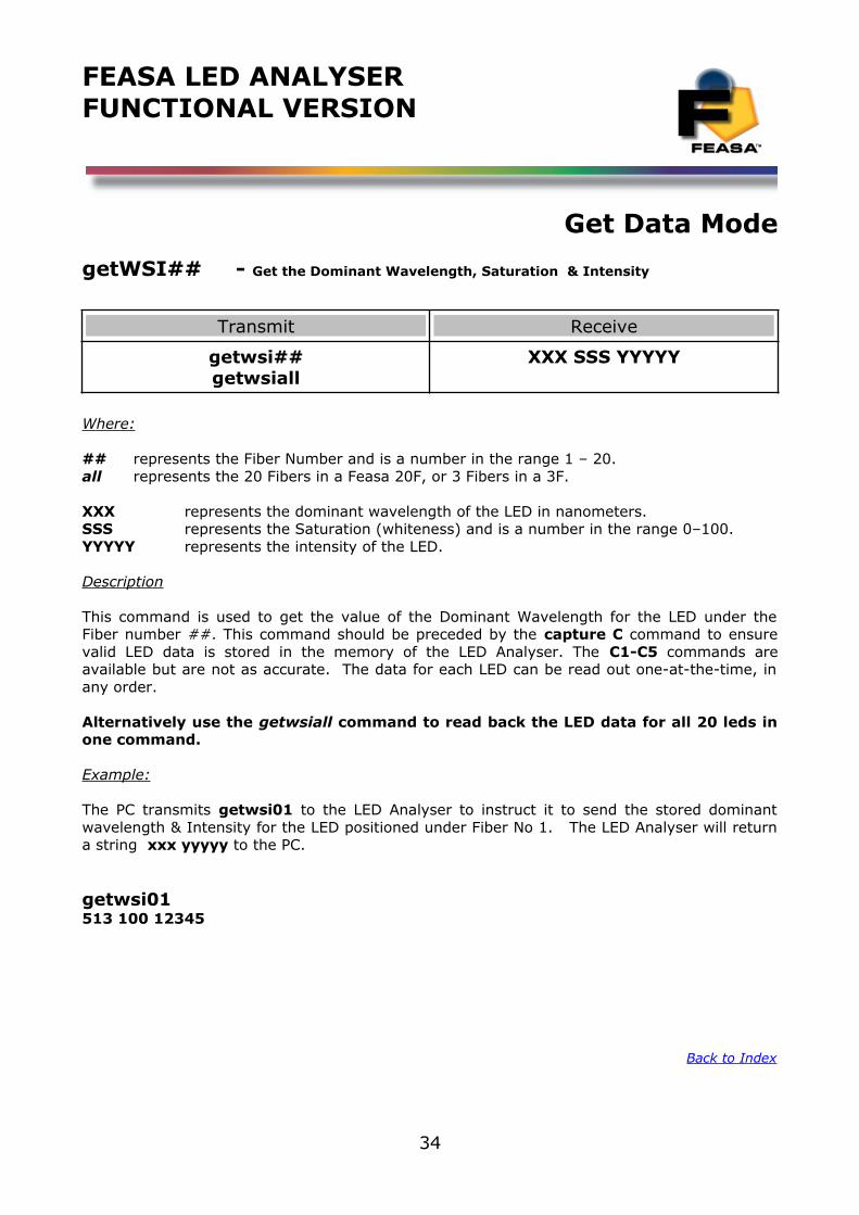
getWSI## - Get the Dominant Wavelength, Saturation & Intensity
Transmit Receive
getwsi##getwsiall
XXX SSS YYYYY
Where:
## represents the Fiber Number and is a number in the range 1 – 20.all represents the 20 Fibers in a Feasa 20F, or 3 Fibers in a 3F.
XXX represents the dominant wavelength of the LED in nanometers.SSS represents the Saturation (whiteness) and is a number in the range 0–100.YYYYY represents the intensity of the LED.
Description
This command is used to get the value of the Dominant Wavelength for the LED under theFiber number ##. This command should be preceded by the capture C command to ensurevalid LED data is stored in the memory of the LED Analyser. The C1-C5 commands areavailable but are not as accurate. The data for each LED can be read out one-at-the-time, inany order.
Alternatively use the getwsiall command to read back the LED data for all 20 leds inone command.
Example:
The PC transmits getwsi01 to the LED Analyser to instruct it to send the stored dominantwavelength & Intensity for the LED positioned under Fiber No 1. The LED Analyser will returna string xxx yyyyy to the PC.
getwsi01513 100 12345
Back to Index
34
FEASA LED ANALYSERFUNCTIONAL VERSION
Get Data Mode
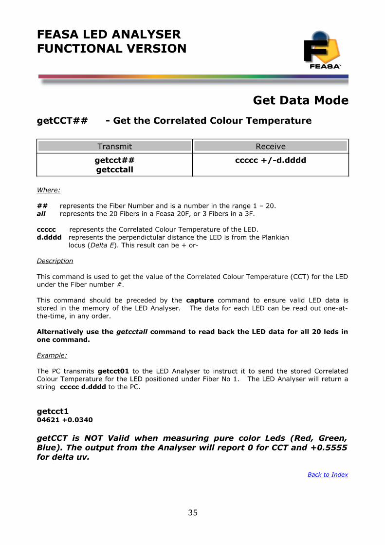
getCCT## - Get the Correlated Colour Temperature
Transmit Receive
getcct##getcctall
ccccc +/-d.dddd
Where:
## represents the Fiber Number and is a number in the range 1 – 20.all represents the 20 Fibers in a Feasa 20F, or 3 Fibers in a 3F.
ccccc represents the Correlated Colour Temperature of the LED.d.dddd represents the perpendictular distance the LED is from the Plankian locus (Delta E). This result can be + or-
Description
This command is used to get the value of the Correlated Colour Temperature (CCT) for the LEDunder the Fiber number #.
This command should be preceded by the capture command to ensure valid LED data isstored in the memory of the LED Analyser. The data for each LED can be read out one-at-the-time, in any order.
Alternatively use the getcctall command to read back the LED data for all 20 leds inone command.
Example:
The PC transmits getcct01 to the LED Analyser to instruct it to send the stored CorrelatedColour Temperature for the LED positioned under Fiber No 1. The LED Analyser will return astring ccccc d.dddd to the PC.
getcct104621 +0.0340
getCCT is NOT Valid when measuring pure color Leds (Red, Green,Blue). The output from the Analyser will report 0 for CCT and +0.5555for delta uv.
Back to Index
35
FEASA LED ANALYSERFUNCTIONAL VERSION
Get Data Mode
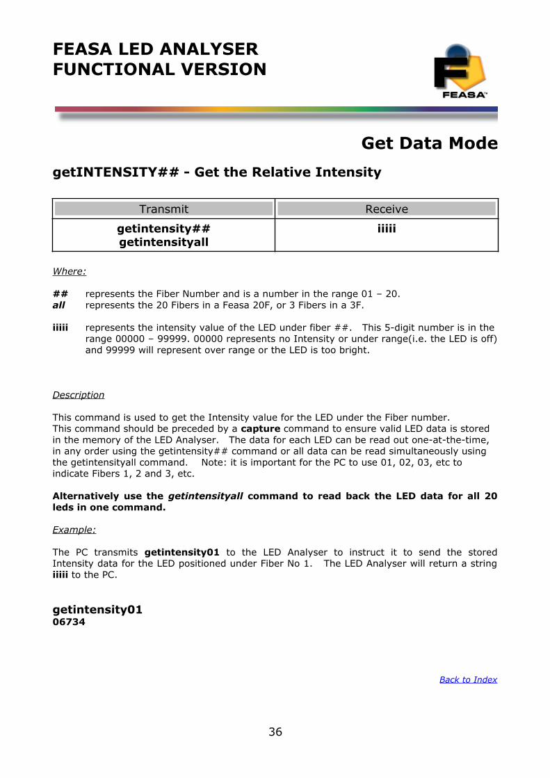
getINTENSITY## - Get the Relative Intensity
Transmit Receive
getintensity##getintensityall
iiiii
Where:
## represents the Fiber Number and is a number in the range 01 – 20.all represents the 20 Fibers in a Feasa 20F, or 3 Fibers in a 3F.
iiiii represents the intensity value of the LED under fiber ##. This 5-digit number is in the range 00000 – 99999. 00000 represents no Intensity or under range(i.e. the LED is off)and 99999 will represent over range or the LED is too bright.
Description
This command is used to get the Intensity value for the LED under the Fiber number. This command should be preceded by a capture command to ensure valid LED data is stored in the memory of the LED Analyser. The data for each LED can be read out one-at-the-time, in any order using the getintensity## command or all data can be read simultaneously using the getintensityall command. Note: it is important for the PC to use 01, 02, 03, etc to indicate Fibers 1, 2 and 3, etc.
Alternatively use the getintensityall command to read back the LED data for all 20leds in one command.
Example:
The PC transmits getintensity01 to the LED Analyser to instruct it to send the storedIntensity data for the LED positioned under Fiber No 1. The LED Analyser will return a stringiiiii to the PC.
getintensity0106734
Back to Index
36
FEASA LED ANALYSERFUNCTIONAL VERSION
Get Data Mode
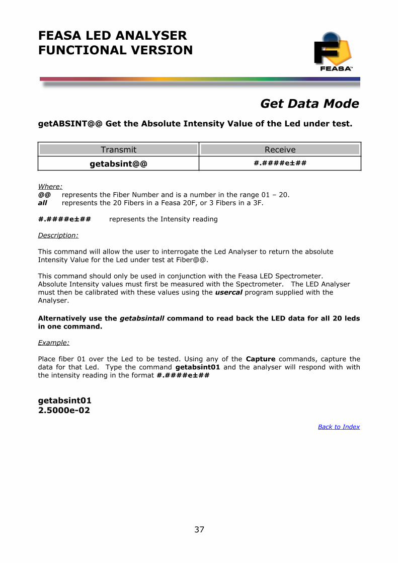
getABSINT@@ Get the Absolute Intensity Value of the Led under test.
Transmit Receive
getabsint@@ #.####e±##
Where:@@ represents the Fiber Number and is a number in the range 01 – 20.all represents the 20 Fibers in a Feasa 20F, or 3 Fibers in a 3F.
#.####e±## represents the Intensity reading
Description:
This command will allow the user to interrogate the Led Analyser to return the absolute Intensity Value for the Led under test at Fiber@@.
This command should only be used in conjunction with the Feasa LED Spectrometer. Absolute Intensity values must first be measured with the Spectrometer. The LED Analyser must then be calibrated with these values using the usercal program supplied with the Analyser.
Alternatively use the getabsintall command to read back the LED data for all 20 ledsin one command.
Example:
Place fiber 01 over the Led to be tested. Using any of the Capture commands, capture thedata for that Led. Type the command getabsint01 and the analyser will respond with withthe intensity reading in the format #.####e±##
getabsint012.5000e-02
Back to Index
37
FEASA LED ANALYSERFUNCTIONAL VERSION
Get Data Mode
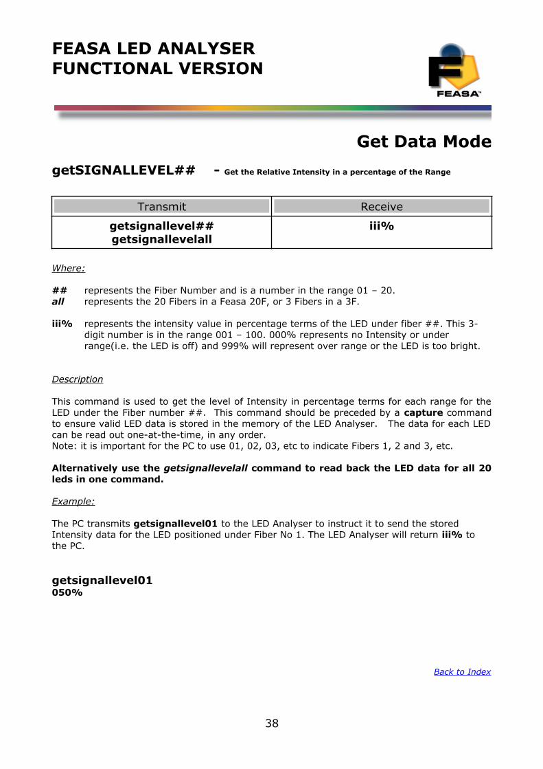
getSIGNALLEVEL## - Get the Relative Intensity in a percentage of the Range
Transmit Receive
getsignallevel##getsignallevelall
iii%
Where:
## represents the Fiber Number and is a number in the range 01 – 20.all represents the 20 Fibers in a Feasa 20F, or 3 Fibers in a 3F.
iii% represents the intensity value in percentage terms of the LED under fiber ##. This 3-digit number is in the range 001 – 100. 000% represents no Intensity or under range(i.e. the LED is off) and 999% will represent over range or the LED is too bright.
Description
This command is used to get the level of Intensity in percentage terms for each range for theLED under the Fiber number ##. This command should be preceded by a capture commandto ensure valid LED data is stored in the memory of the LED Analyser. The data for each LEDcan be read out one-at-the-time, in any order. Note: it is important for the PC to use 01, 02, 03, etc to indicate Fibers 1, 2 and 3, etc.
Alternatively use the getsignallevelall command to read back the LED data for all 20leds in one command.
Example:
The PC transmits getsignallevel01 to the LED Analyser to instruct it to send the stored Intensity data for the LED positioned under Fiber No 1. The LED Analyser will return iii% to the PC.
getsignallevel01050%
Back to Index
38
FEASA LED ANALYSERFUNCTIONAL VERSION
Get Data Mode
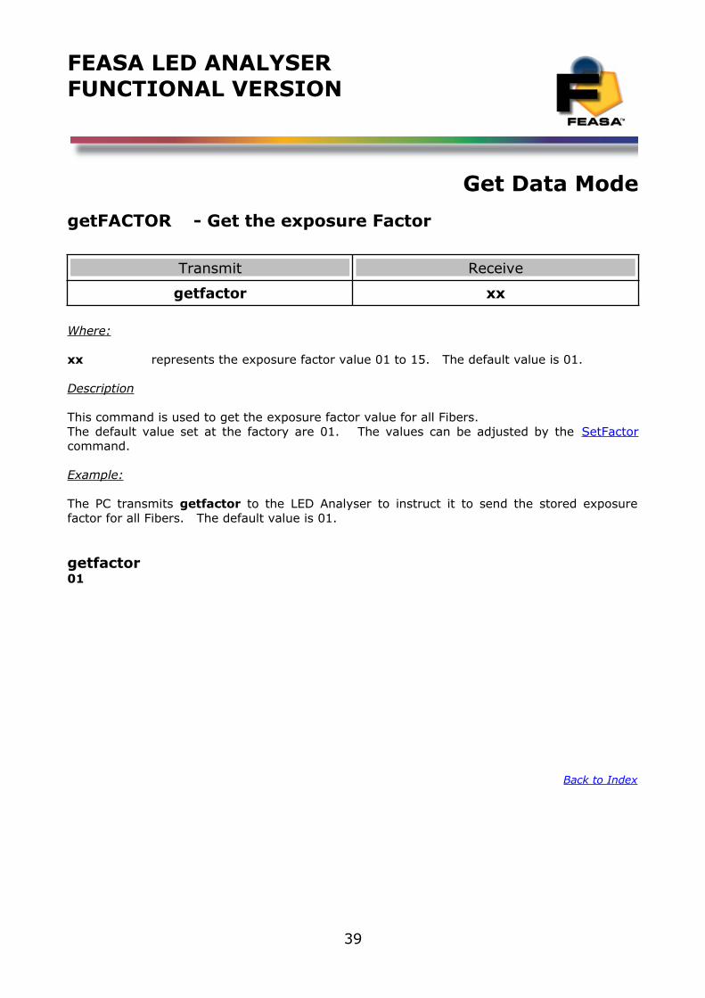
getFACTOR - Get the exposure Factor
Transmit Receive
getfactor xx
Where:
xx represents the exposure factor value 01 to 15. The default value is 01.
Description
This command is used to get the exposure factor value for all Fibers. The default value set at the factory are 01. The values can be adjusted by the SetFactorcommand.
Example:
The PC transmits getfactor to the LED Analyser to instruct it to send the stored exposurefactor for all Fibers. The default value is 01.
getfactor01
Back to Index
39
FEASA LED ANALYSERFUNCTIONAL VERSION
Get Data Mode
get7SEG# - Get the value of a 7 Segment Display
Transmit Receive
get7seg# x
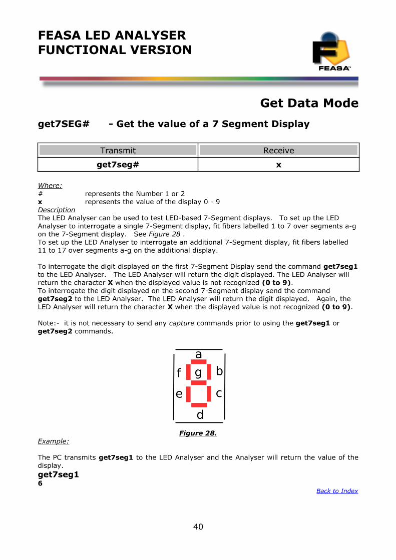
Where:# represents the Number 1 or 2x represents the value of the display 0 - 9DescriptionThe LED Analyser can be used to test LED-based 7-Segment displays. To set up the LED Analyser to interrogate a single 7-Segment display, fit fibers labelled 1 to 7 over segments a-gon the 7-Segment display. See Figure 28 . To set up the LED Analyser to interrogate an additional 7-Segment display, fit fibers labelled 11 to 17 over segments a-g on the additional display.
To interrogate the digit displayed on the first 7-Segment Display send the command get7seg1to the LED Analyser. The LED Analyser will return the digit displayed. The LED Analyser will return the character X when the displayed value is not recognized (0 to 9). To interrogate the digit displayed on the second 7-Segment display send the command get7seg2 to the LED Analyser. The LED Analyser will return the digit displayed. Again, the LED Analyser will return the character X when the displayed value is not recognized (0 to 9).
Note:- it is not necessary to send any capture commands prior to using the get7seg1 or get7seg2 commands.
Figure 28.Example:
The PC transmits get7seg1 to the LED Analyser and the Analyser will return the value of thedisplay.get7seg16
Back to Index
40
b
c
d
e
f g
a

FEASA LED ANALYSERFUNCTIONAL VERSION
Get Data Mode
getAUTOPWM - Get which Auto Capture Mode is active C or CPWM
Transmit Receive
getautopwm 0 or 1
Where: 0 is Standard Auto Capture (c) and 1 is PWM Auto Capture (cpwm)
Description
This command will verify the Capture mode of the Analyser between Auto Capture (C) and Auto PWM Capture (CPWM). Example:
Connect the Led Analyser to the Feasa Terminal Window and type getstatus. The Analyser will report Auto PWM Mode: OFF or type getautopwm and the Analyser will report 0.
Set a fiber over a Led to test and do an Auto Capture (C). If its a non-pwm Led the Analyser will report useable data for HSI, RGB or XY as requested. However if the LED is actually a PWMLed the Analyser will detect un-useable data in the form XXX. Type the command setautopwm1 to change the capture mode. Repeat the test, The analyser will now mimic the c capture as a cpwm capture and report useable data. Doing a getstatus will now show Auto PWM Mode: ON or getautopwm will report a 1. It will remain in this mode until the user changes the mode by typing the command setautopwm0.
Back to Index
41
FEASA LED ANALYSERFUNCTIONAL VERSION
Get Data Mode
getintensitymode - Get which Intensity Mode is active Logarithmic or Linear
Transmit Receive
getintensitymode Log or Lin
Where: Log is the Logarithmic Mode and Lin is the Linear Mode
Description
The Led Analyser is shipped from the factory in Logarithmic Mode. However it is possible to change the mode to Linear by using the commands set/putlin. To reset the analyser back to log mode use the command set/putlog.
Refer to pages 10,11 of this document for more details
Example:
Connect the Led Analyser to the Feasa Terminal Window and type getintensitymode. The Analyser will report the mode the Intensity output of the Analyser is set to.
Set the Analyser is Linear mode and verify.
putLingetintensitymodeLinear
Back to Index
42
FEASA LED ANALYSERFUNCTIONAL VERSION
Get Data Mode
getPHOTOPIC - Get which Photopic Mode is active
Transmit Receive
getphotopic 0 or 1 or 2
Where: 0 is Photopic Response OFF1 is Response Photometric2 is Response Radiometric
Description
The Led Analyser is shipped from the factory in photopic mode 1. This corrects the Absolute Intensity to reproduce the photometric response (for lm, mcd). This can be verified by typing the command getphotopic with the answer 1.
The photopic mode can be set to a radiometric response by sending the command setphotopic2. This corrects the Absolute Intensity to reproduce the radiometric response (for mW)
This command is only available on Software Rev F210 upwards
Back to Index
43
FEASA LED ANALYSERFUNCTIONAL VERSION
General Commands
getBAUD- Get the Baud Rate
Transmit Receive
getBAUD X bps
Where: X = 9600, 19200, 38400, 57600, 115200 for Serial RS232 Port
Where: X = 9600, 19200, 38400, 57600, 115200, 230400, 460800, 921600 for USB Port
Description
This command will get the baud rate of the Serial and USB Port's that the Analyser iscommunication through. The default Port settings of the Analyser are 57,600, 8 Data bits, 1 Stop bit and No Parity.
It can also be seen on the comment section of the Feasa terminal window.
Example:
To get the baud rate of the Analyser transmit the command getbaud to the Analyser.
getbaud57600 bps
Back to Index
44
FEASA LED ANALYSERFUNCTIONAL VERSION
General Commands
getHW - Get the Hardware Version
Transmit Receive
getHW Feasa XX-YY
Where: XX-YY is an alphanumeric value.
Description
This command will return the hardware version the Analyser.
Example:
The PC transmits gethw to the LED Analyser an it will return Feasa XX-YY to the PC.
gethwFeasa 20-ForFeasa 20FB
Back to Index
45
FEASA LED ANALYSERFUNCTIONAL VERSION
General Commands
getSTATUS - Get a summary of the Led Analyser details
Transmit Receive
getstatus See details below
Information Received back from the Analyser:
Hardware: Feasa xx-ySerial number : XyyyFirmware Version : IyyyIntensity Mode : LogarithmicPhotopic response: ONExposure Factor : 01Capture : Manuel 04Auto PWM mode: OFFNumber of Fibers : 05External Trigger status: DisabledColour Gains: xxx xxx xxxEnd of Transmission Character: DisabledSelected calibration set: 00user calibration date: dd/mm/yyyyFactory calibration date: dd/mm/yyyy
DescriptionThis command will return a summary of the Led Analyser details.
Example:The PC transmits getstatus to the LED Analyser and it will return to the PC.
Led Analyser STATUSHardware: Feasa 20-FSerial Number : J001Firmware Version :F123Intensity Mode : LogarithmicPhotopic response: ONExposure Factor: 01Last Capture : Manuel 04Auto PWM Mode: OFFNumber of Fibers : 20External Trigger Status: DisabledColour Gains: 100 150 100End of Transmission Character: DisabledSelected calibration set: 0User Calibration Date: 01/01/2015Factory calibration date: 23/10/2016
Back to Index
46
FEASA LED ANALYSERFUNCTIONAL VERSION
General Commands
getSERIAL Get the Serial Number of the Analyser
Transmit Receive
getSerial xxxx
Where: xxxx is an alphanumeric value. (Always 4 characters)
Description
This command will return the Serial Number of the Analyser. This is a unique number and isuseful if multiple LED Analysers are used in a System. The Controlling Software can queryeach LED Analyser for it's Serial Number to ensure the correct Analyser is being controlled.
Example:
The PC transmits getserial to the LED Analyser an it will return xxxx to the PC.
getserial75A6
Back to Index
47
FEASA LED ANALYSERFUNCTIONAL VERSION
General Commands
getVERSION - Get the Firmware Version
Transmit Receive
getVersion xxxx
Where: xxxx is an alphanumeric value. (Always 4 characters)
Description
This command will return the Version Number of the firmware in the Analyser.
Example:
The PC transmits getversion to the LED Analyser an it will return xxxx to the PC.
getversionF122
Back to Index
48
FEASA LED ANALYSERFUNCTIONAL VERSION
General Commands
EOT - End of Transmission Character
Transmit Receive
enableeotdisableeot
See details below
Description
Every command sent to the LED Analyser or response received from the Led Analyser, endswith a set of characters that indicates that the command or response has finished. Thosecharacters are CR + LF, which are ASCII characters 13 and 10 respectively. Alternatively,responses from the LED Analyser can also have an end-of-transmission format like CR + LF +EOT, which are the ASCII characters 13, 10 and 04 respectively. CR + LF are always present,but character EOT can be enabled or disabled using the commands ENABLEEOT andDISABLEEOT. Having EOT character enabled can be extremely useful in multi-line commands,since this allows to differentiate between the end of a line and the end of a transmission.
The EOT command is disabled by default. To enable EOT simply send the command enableeotusing Feasa Terminal software. The Analyser will maintain the EOT state even when poweredoff. To disable the state just send the command disableeot.
Information Received back from the Analyser using the getstatus command is as follows:
Hardware: Feasa xx-ySerial number : XyyyFirmware Version : IyyyIntensity Mode : LogarithmicPhotopic response: ONExposure Factor : 01Capture : Manuel 04Auto PWM mode : OFFNumber of Fibers : 05External Trigger status: DisabledColour Gains: 100 150 100End of Transmission Character: DisabledSelected calibration set: 0user calibration date: dd/mm/yyyyFactory calibration date: dd/mm/yyyy
Back to Index
49
FEASA LED ANALYSERFUNCTIONAL VERSION
General Set/Put Commands
General Set / Put Commands
IMPORTANT INFORMATION for Programmers
set / put Commands
The Set / Put commands are used to adjust various settings in the LED Analyser such as Intensity, Exposure and offsets.
The Set commands are written to the on-board Flash.
These settings remain programmed in the Analyser even when the power is removed.The Led Analyser has a capacity limit of approximately 100,000 writes to the flash.
Use the Set command only to store relevant information on the Led Analyser. Please refrainfrom using Set commands in your high volume production programs as this constant writing tothe Flash will eventually corrupt the Led Analyser. Use the Put command instead.
The Put commands are written to the on-board RAM.
These settings will NOT remain programmed in the Analyser after the power is removed.
Use the Put command as often as you need in your program. This will prolong the life of theLed Analyser particularly in high volume testing environment.
Commands are transmitted and received using ASCII characters and are case-insensitive.All commands must be terminated with a <CR> or <LF> character.
Back to Index
50
FEASA LED ANALYSERFUNCTIONAL VERSION
Set Data Mode
set/putFACTOR## - Set the Exposure Factor
Transmit Receive
setfactor##putfactor##
OKOK
Where:
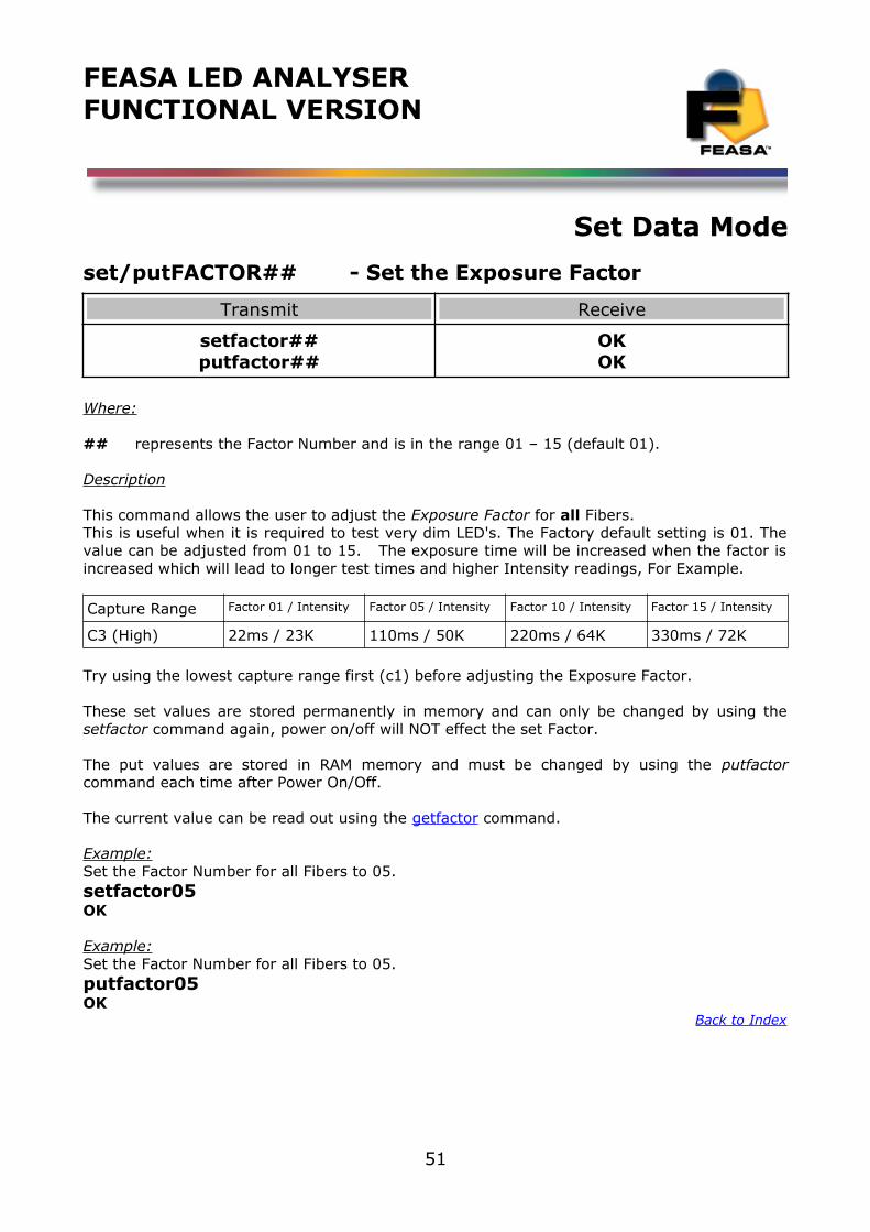
## represents the Factor Number and is in the range 01 – 15 (default 01).
Description
This command allows the user to adjust the Exposure Factor for all Fibers. This is useful when it is required to test very dim LED's. The Factory default setting is 01. Thevalue can be adjusted from 01 to 15. The exposure time will be increased when the factor isincreased which will lead to longer test times and higher Intensity readings, For Example.
Capture Range Factor 01 / Intensity Factor 05 / Intensity Factor 10 / Intensity Factor 15 / Intensity
C3 (High) 22ms / 23K 110ms / 50K 220ms / 64K 330ms / 72K
Try using the lowest capture range first (c1) before adjusting the Exposure Factor.
These set values are stored permanently in memory and can only be changed by using thesetfactor command again, power on/off will NOT effect the set Factor.
The put values are stored in RAM memory and must be changed by using the putfactorcommand each time after Power On/Off.
The current value can be read out using the getfactor command.
Example:Set the Factor Number for all Fibers to 05.setfactor05OK
Example:Set the Factor Number for all Fibers to 05.putfactor05OK
Back to Index
51
FEASA LED ANALYSERFUNCTIONAL VERSION
Set Data Mode
set/putLOG - Change the Intensity Response of the Analyser to Logarithmic mode
Transmit Receive
setlogputlog
OKOK
Description
This command will change the Intensity Response of the Analyser to measure in Logarithmicmode. All Analysers shipped from the factory are set in Log mode.
Please refer to the Intensity Section of this document page 8 Intensity
The set command is stored permanently in memory and can only be changed by using thesetlog command again, power on/off will NOT effect the setlog
The put values are stored in RAM memory and must be changed by using the putlog commandeach time after Power On/Off.
Example:setlogOK
Example:putlogOK
Back to Index
52
FEASA LED ANALYSERFUNCTIONAL VERSION
Set Data Mode
set/putLIN - Change the Intensity response of the Analyser to Linear Mode
Transmit Receive
setlinputlin
OKOK
Description
This command will change the Intensity Response of the Analyser to measure in Linear mode.All Analysers shipped from the factory are set in Log mode.
Please refer to the Intensity Section of this document page 8 Intensity
The set command is stored permanently in memory and can only be changed by using thesetlin command again, power on/off will NOT effect the setlin
The put values are stored in RAM memory and must be changed by using the putlin commandeach time after Power On/Off.
Example:setlinOK
Example:putlinOK
Back to Index
53
FEASA LED ANALYSERFUNCTIONAL VERSION
General set/put Commands
setBAUD - Change the baud rate
Transmit Receive
Setbaudxxxxx OK
Where: X = 9600, 19200, 38400, 57600, 115200 for Serial RS232 Port
Where: X = 9600, 19200, 38400, 57600, 115200, 230400, 460800, 921600 for USB Port
Description
This command will change the baud rate of the Serial and USB Port's in the Analyser. The default Port settings of the Analyser are 57,600, 8 Data bits, 1 Stop bit and No Parity. If an incompatible baud rate is selected the Analyser will not respond. Please disconnect andreconnect the Analyser to return the Analyser to the default 57600 bps. A correct baud rateselected will remain stored in memory even after power off. The command getbaud will return the set baud rate. It can also be seen on the commentsection of the Feasa terminal window.
Test times are improved by increasing the baudrate from the default to higher values and thiscan be further enhanced by decreasing the latency (windows default 16) to latency of 1. Referto the App Note in the documentation folder of the CD to carry out this.
Example:
To change the baud rate to 19,200 transmit the command setbaud19200 to the Analyser .
setbaud19200OK
Back to Index
54
FEASA LED ANALYSERFUNCTIONAL VERSION
General set/put Commands
setAUTOPWM# - Change the Auto Capture mode to Auto PWM Mode
Transmit Receive
setautopwm# OK
Where: # = 0 for OFF and 1 for ON,
Description
This command will change the Auto Capture mode of the Analyser from an Auto Capture to anAuto PWM Capture should the Led Analyser detect a blinking Led. Example:
Connect the Led Analyser to the Feasa Terminal Window and type getstatus. The Analyser will report Auto PWM Mode: OFF. Set your fiber over a Led and do an Auto Capture (C). If its a standard Led the Analyser will report useable data for HSI, RGB or XY as requested. However ifthe LED is actually a PWM Led the Analyser will detect un-useable data in the form XXX. To compensate for for this type the command setautopwm1 to change the capture mode. Repeat the test, The analyser will now mimic the c capture as a cpwm capture and report useable data. Doing a getstatus will now show Auto PWM Mode: ON or getautopwm will report a 1. It will remain in this mode until the user changes the mode by typing the command setautopwm0.
This command is only available on Software Rev F207 upwardsBack to Index
55
FEASA LED ANALYSERFUNCTIONAL VERSION
Get Data Mode
setPHOTOPIC - Set which Photopic Mode you require
Transmit Receive
setphotopic# OK
Where #: 0 is Photopic Response OFF1 is Response Photometric (Default from the Factory)2 is Response Radiometric
Description
The Led Analyser is shipped from the factory in photopic mode 1. This corrects the Absolute Intensity to reproduce the photometric response (for lm, mcd). This can be verified by typing the command getphotopic with the answer 1.
The photopic mode can be set to a radiometric response by sending the command setphotopic2. This corrects the Absolute Intensity to reproduce the radiometric response (for mW)
The photopic mode can be turned OFF by sending the command setphotopic0. With the Analyser in this mode there is no effect on Absolute Intensity.
This command is only available on Software Rev F210 upwards
Back to Index
56
FEASA LED ANALYSERFUNCTIONAL VERSION
User Calibration Mode
User Calibration Mode
Introduction:
The user calibration mode function allows up to 51 (00 to 50) different calibration sets to be simultaneously stored on the Led Analyser. The Analyser is shipped from the factory in set mode 00. setcalibration## (## is 00 to 50) will enable which set you want to work in. While inthis mode you can vary the Relevant Intensity, Absolute Intensity, xy offset, wavelength offset, and RGB gains and then save them in that version or set. The date of this user calibration can also be saved using the command setcalibrationdatedd/mm/yyyy. Using the getstatus or getcalibrationset commands the Led Analyser will display which user calibration set you are enabled in and also the date you set it up.For example if you are testing a board which has 2 different led Colour options you could setcalibration01, adjust your gains or offsets as necessary and proceed to test your version 01 board. setcalibration02 and now adjust you gains or offsets as necessary for your other versionof the board and proceed to test your version 02 of the board. The user calibration date for each set can be saved also.
Before doing the Calibration, we recommend you select the proper capture mode and range forthe Leds you are testing. Standard Capture (C, C1, C2….) mode is recommended for static Leds whereas Capture PWM (eg. c2pwm05) is recommended for RGB LEDs that are pulsing.
Select the relevant Range (Low, Medium High, Super & Ultra) by measuring the Led color to be measured in the production. Ensure the signal level is > 30 % in order to maximize the repeatability.
For PWM mode you also need to select the best average factor (00-15) by doing a repeatability analysis on the final colour. The higher the average number, the more repeatable the results will be, However the higher the average the longer the capture time will be required. The Feasa User software has a repeatability test analysis to help you on this task.
When this data is accumulated then proceed with the calibration. Feasa provide a program called UserCal on the CD to accomplish this process. However should you wish to undertake the process manually please refer to the procedure below.
Back to Index
57
FEASA LED ANALYSERFUNCTIONAL VERSION
User Calibration ModeThis is a manual procedure to calibrate the Led Analyser. However we recommend to use the Feasa UserCal program provided on the CD. Each command is detailed in the section below.
UserCal Manual Procedure:1. Select Calibration set
- setcalibrationset## (00-50)
2. Reset Analyser to factory defaults:- resetusercal (Reset all parameters to Factory default)
3. Capture (auto, manual, pwm)- capture
4. Dominant Wavelength reading- getwavelength@@Dominant Wavelength Correction Offset- setwavelengthoffset@@##
5. Relative Intensity Reading for Fiber @@- getintensity@@Relative Intensity Correction Factor- setintgain@@###
6. CIE xy Reading for Fiber@@- getxy@@CIE Correction Offsets- setxoffset@@± 0.###- setyoffset@@± 0.###
7. Absolute Intensity Reading for Fiber@@- getabsint@@Absolute Intensity Correction Factor- setabsintmult@@1.00000e+00 (set the multiplier to 1)- capture (auto, manual, pwm)- getabsint@@ (get the absolute intensity using a multiplier of 1) - i.iiiie±00 (absolute intensity based on a multiplier of 1)- Divide the Desired Intensity by i.iiiie±00 (result will be new multiplier m.mmmmmE±ee)- setabsintmult@@m.mmmmmE±ee (set the new multiplier to o/p the desired Absolute Int.)- getabsint@@ (get the absolute intensity using new multiplier)- #.####e±## (Absolute Intensity in Scientific Notation Format)
8. Set the user calibration date:- setcalibrationdatedd/mm/yyyy
Note1: you can skip the adjustment of a particular parameter if you don't need it.Note2: if you require dominant wavelength and absolute intensity, make sure the wavelength correction is done first as it affects the absolute intensity readings.
Back to Index
58
FEASA LED ANALYSERFUNCTIONAL VERSION
User Calibration Mode
set/putINTGAIN - Set the Intensity GainFactor
Transmit Receive
Setintgain##xxxputintgain##xxx
OKOK
Where:
## represents the Fiber Number and is a number in the range 01 – 20.xxx represents a 3 digit gain factor, default 100.
Description
This command allows the user to adjust the Intensity Gain Factor for each Fiber. This is useful when it is required to balance all or some of the Fibers to give the same Intensitywhen testing similar LED's. The Factory default setting is 100 and the value for each Fibercan be adjusted from 050 – 200.
These set values are stored permanently in memory and can only be changed by using thesetIntGain command again.
The put values are stored in RAM memory and must be changed by using the putIntGaincommand each time after Power On/Off.
The command getIntGain will display the current stored gain setting.
Example:
Set the Intensity gain for Fiber 1 to 095.setintgain01095OK
Example:
Set the Intensity gain for Fiber 1 to 095.putintgain01095OK
Back to Index
59
FEASA LED ANALYSERFUNCTIONAL VERSION
User Calibration Mode
getINTGAIN## - Get the Intensity Gain Factor
Transmit Receive
getIntGain## xxx
Where:
## represents the Fiber Number and is a number in the range 01 – 20.xxx represents the Intensity gain value. Default 100.
Description
This command is used to get the Intensity gain value for each Fiber. The default values set at the factory are 100 i.e. 100% of nominal. The values can beadjusted by the SetIntGain command.
Example:
The PC transmits getintgain01 to the LED Analyser to instruct it to send the stored intensitygain data for Fiber No 1.
getintgain01100
Back to Index
60
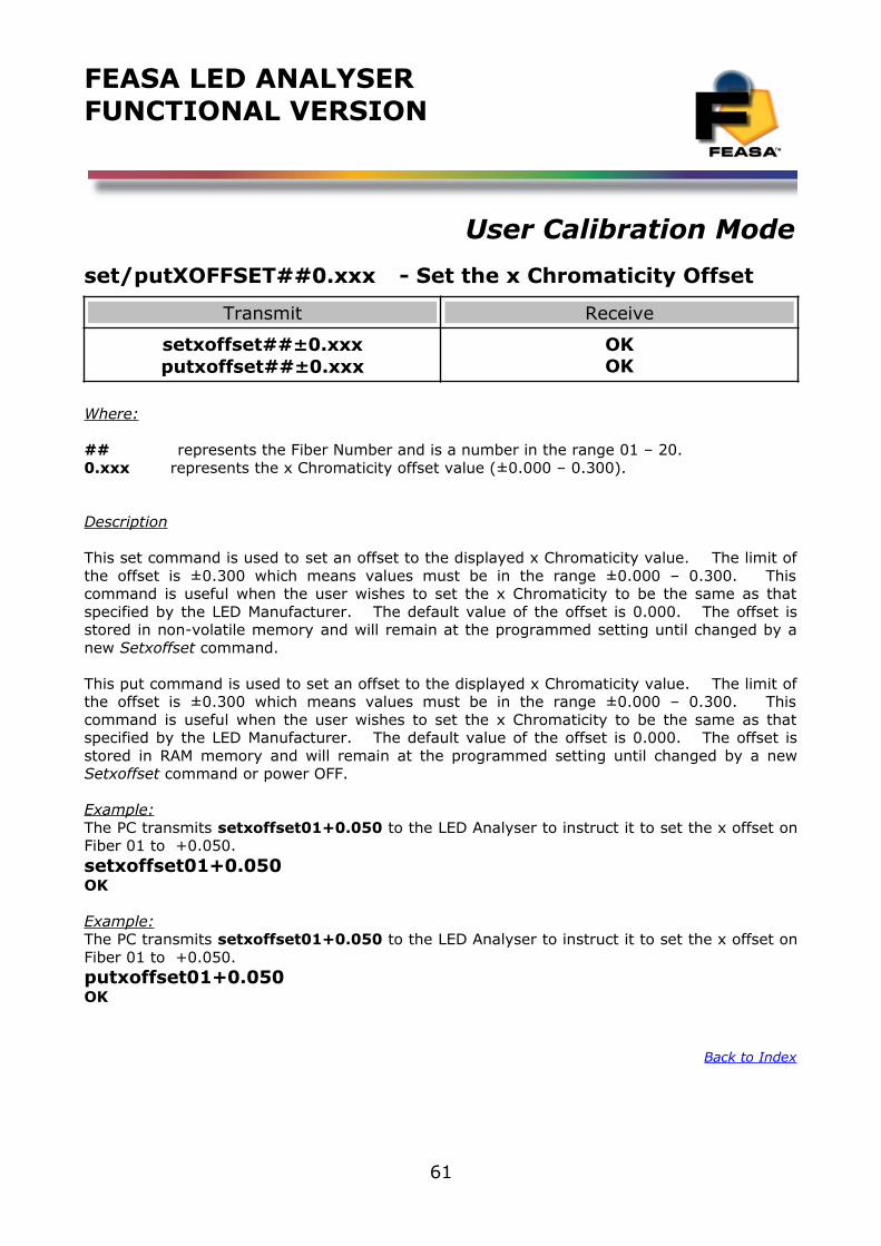
FEASA LED ANALYSERFUNCTIONAL VERSION
User Calibration Mode
set/putXOFFSET##0.xxx - Set the x Chromaticity Offset
Transmit Receive
setxoffset##±0.xxxputxoffset##±0.xxx
OKOK
Where:
## represents the Fiber Number and is a number in the range 01 – 20.0.xxx represents the x Chromaticity offset value (±0.000 – 0.300).
Description
This set command is used to set an offset to the displayed x Chromaticity value. The limit ofthe offset is ±0.300 which means values must be in the range ±0.000 – 0.300. Thiscommand is useful when the user wishes to set the x Chromaticity to be the same as thatspecified by the LED Manufacturer. The default value of the offset is 0.000. The offset isstored in non-volatile memory and will remain at the programmed setting until changed by anew Setxoffset command.
This put command is used to set an offset to the displayed x Chromaticity value. The limit ofthe offset is ±0.300 which means values must be in the range ±0.000 – 0.300. Thiscommand is useful when the user wishes to set the x Chromaticity to be the same as thatspecified by the LED Manufacturer. The default value of the offset is 0.000. The offset isstored in RAM memory and will remain at the programmed setting until changed by a newSetxoffset command or power OFF.
Example:The PC transmits setxoffset01+0.050 to the LED Analyser to instruct it to set the x offset onFiber 01 to +0.050.setxoffset01+0.050OK
Example:The PC transmits setxoffset01+0.050 to the LED Analyser to instruct it to set the x offset onFiber 01 to +0.050.putxoffset01+0.050OK
Back to Index
61
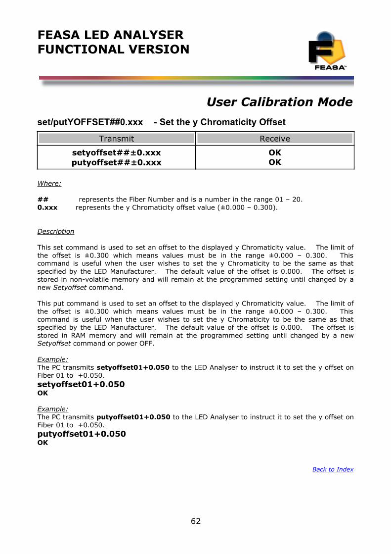
FEASA LED ANALYSERFUNCTIONAL VERSION
User Calibration Mode
set/putYOFFSET##0.xxx - Set the y Chromaticity Offset
Transmit Receive
setyoffset##±0.xxxputyoffset##±0.xxx
OKOK
Where:
## represents the Fiber Number and is a number in the range 01 – 20.0.xxx represents the y Chromaticity offset value (±0.000 – 0.300).
Description
This set command is used to set an offset to the displayed y Chromaticity value. The limit ofthe offset is ±0.300 which means values must be in the range ±0.000 – 0.300. Thiscommand is useful when the user wishes to set the y Chromaticity to be the same as thatspecified by the LED Manufacturer. The default value of the offset is 0.000. The offset isstored in non-volatile memory and will remain at the programmed setting until changed by anew Setyoffset command.
This put command is used to set an offset to the displayed y Chromaticity value. The limit ofthe offset is ±0.300 which means values must be in the range ±0.000 – 0.300. Thiscommand is useful when the user wishes to set the y Chromaticity to be the same as thatspecified by the LED Manufacturer. The default value of the offset is 0.000. The offset isstored in RAM memory and will remain at the programmed setting until changed by a newSetyoffset command or power OFF.
Example:The PC transmits setyoffset01+0.050 to the LED Analyser to instruct it to set the y offset onFiber 01 to +0.050.setyoffset01+0.050OK
Example:The PC transmits putyoffset01+0.050 to the LED Analyser to instruct it to set the y offset onFiber 01 to +0.050.putyoffset01+0.050OK
Back to Index
62
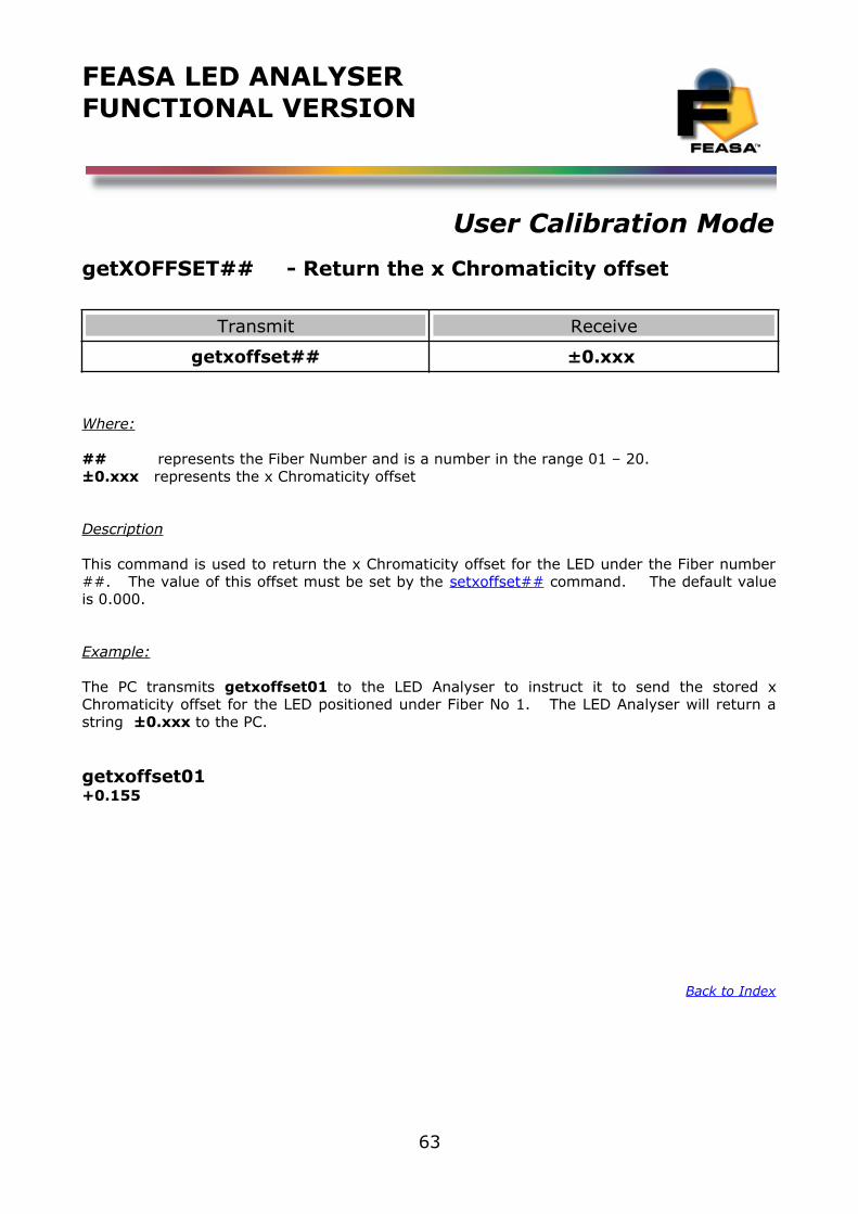
FEASA LED ANALYSERFUNCTIONAL VERSION
User Calibration Mode
getXOFFSET## - Return the x Chromaticity offset
Transmit Receive
getxoffset## ±0.xxx
Where:
## represents the Fiber Number and is a number in the range 01 – 20.±0.xxx represents the x Chromaticity offset
Description
This command is used to return the x Chromaticity offset for the LED under the Fiber number##. The value of this offset must be set by the setxoffset## command. The default valueis 0.000.
Example:
The PC transmits getxoffset01 to the LED Analyser to instruct it to send the stored xChromaticity offset for the LED positioned under Fiber No 1. The LED Analyser will return astring ±0.xxx to the PC.
getxoffset01+0.155
Back to Index
63
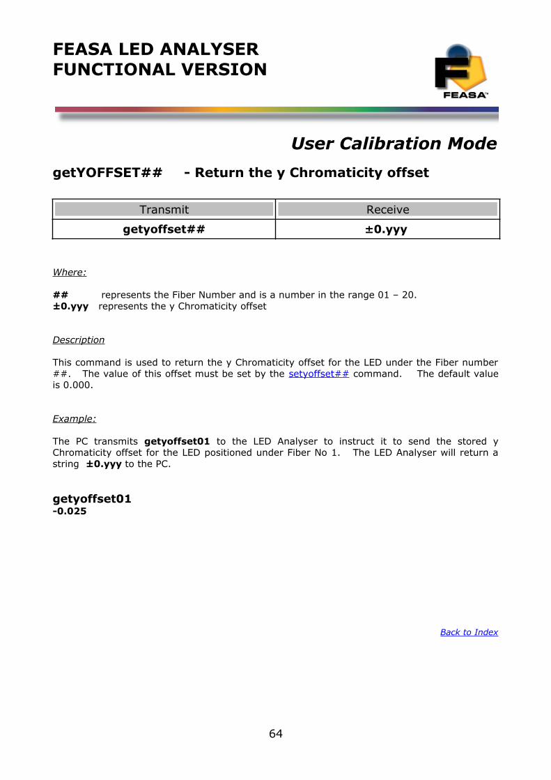
FEASA LED ANALYSERFUNCTIONAL VERSION
User Calibration Mode
getYOFFSET## - Return the y Chromaticity offset
Transmit Receive
getyoffset## ±0.yyy
Where:
## represents the Fiber Number and is a number in the range 01 – 20.±0.yyy represents the y Chromaticity offset
Description
This command is used to return the y Chromaticity offset for the LED under the Fiber number##. The value of this offset must be set by the setyoffset## command. The default valueis 0.000.
Example:
The PC transmits getyoffset01 to the LED Analyser to instruct it to send the stored yChromaticity offset for the LED positioned under Fiber No 1. The LED Analyser will return astring ±0.yyy to the PC.
getyoffset01-0.025
Back to Index
64
FEASA LED ANALYSERFUNCTIONAL VERSION
User Calibration Mode
set/putWAVELENGTHOFFSET@@±## - Set the wavelength Offset
Transmit Receive
setwavelengthoffset##±xxputwavelengthoffset##±xx
OKOK
Where:
@@ represents the Fiber Number and is a number in the range 01 – 20.xx represents the wavelength offset value (±99).
Description
This set command is used to set an offset to the wavelength value. The limit of the offset is±99. This command is useful when the user wishes to set the wavelength to be the same asthat specified by the LED Manufacturer. The default value of the offset is 00. The offset isstored in non-volatile memory and will remain at the programmed setting until changed by anew setwavelengthoffset command.
This put command is used to set an offset to the wavelength value. The limit of the offset is±99. This command is useful when the user wishes to set the wavelength to be the same asthat specified by the LED Manufacturer. The default value of the offset is 00. The offset isstored in RAM memory and will remain at the programmed setting until changed by a newsetwavelengthoffset command or power OFF.
Example:
The PC transmits setwavelengthoffset01-05 to the LED Analyser to instruct it to set thewavelength offset on Fiber 01 to -05.setwavelengthoffset01-05OK
Example:
The PC transmits putwavelengthoffset01-05 to the LED Analyser to instruct it to set thewavelength offset on Fiber 01 to -05.putwavelengthoffset01-05OK
Back to Index
65
FEASA LED ANALYSERFUNCTIONAL VERSION
User Calibration Mode
getWAVELENGTHOFFSET@@ - Get the Dominant Wavelength Offset
Transmit Receive
getwavelengthoffset@@ +/-XX
Where:
@@ represents the Fiber Number and is a number in the range 1 – 20.+/- xx represents the wavelength offset set of the LED in nanometers.
Description
This command is used to get the value of the Dominant Wavelength Offset set for Fibernumber @@. The range of value that can be programmed is +/-99, however setting a value of greater than+/-10 would probably indicate an error in your measurement setup
Example:
The PC transmits getwavelengthoffset01 to the LED Analyser to instruct it to send theprogrammed dominant wavelength offset for the LED positioned under Fiber No 1. The LEDAnalyser will return a string +/- xx to the PC.
getwavelengthoffset01+07
Back to Index
66
FEASA LED ANALYSERFUNCTIONAL VERSION
User Calibration Mode
set/putABSINTMULT@@ - Set the Absolute Intensity Multiplier Factor
Transmit Receive
setabsintmult@@m.mmmmme+mmputabsintmult@@m.mmmmme+mm
OKOK
Where:
@@ represents the Fiber Number and is a number in the range 01 – 20.m.mmmmme+mm represents the Absolute Intensity Multiplier Factor
Description
The command setabsintmult@@m.mmmmme+mm directs the LED Analyser to set theAbsolute Intensity Multiplier Factor on Fiber @@ to m.mmmmme+mm
Example:send the command setabsintmult@@m.mmmmme+mm to the LED Analyser to instruct itto set the Absolute Intensity Multiplier Factor on Fiber 3 to 1
setabsintmult031.00000e+00OK
Back to Index
67
FEASA LED ANALYSERFUNCTIONAL VERSION
User Calibration Mode
getABSINTMULT@@ Get the Absolute Intensity Correction Factor of the Led under test.
Transmit Receive
getabsintmult@@ #.####e±##
Where:@@ represents the Fiber Number and is a number in the range 01 – 20.#.#####e+## represents the Absolute Intensity Correction Factor
Description:
This command will allow the user to interrogate the Led Analyser to return the absolute Intensity Correction Factor or Multiplier Value for the Led under test at Fiber@@.
Example:
Type the command getabsintmult01 and the analyser will respond with with the Multiplier inthe format 0.00000e+00
getabsintmult010.00000e+00
Back to Index
68
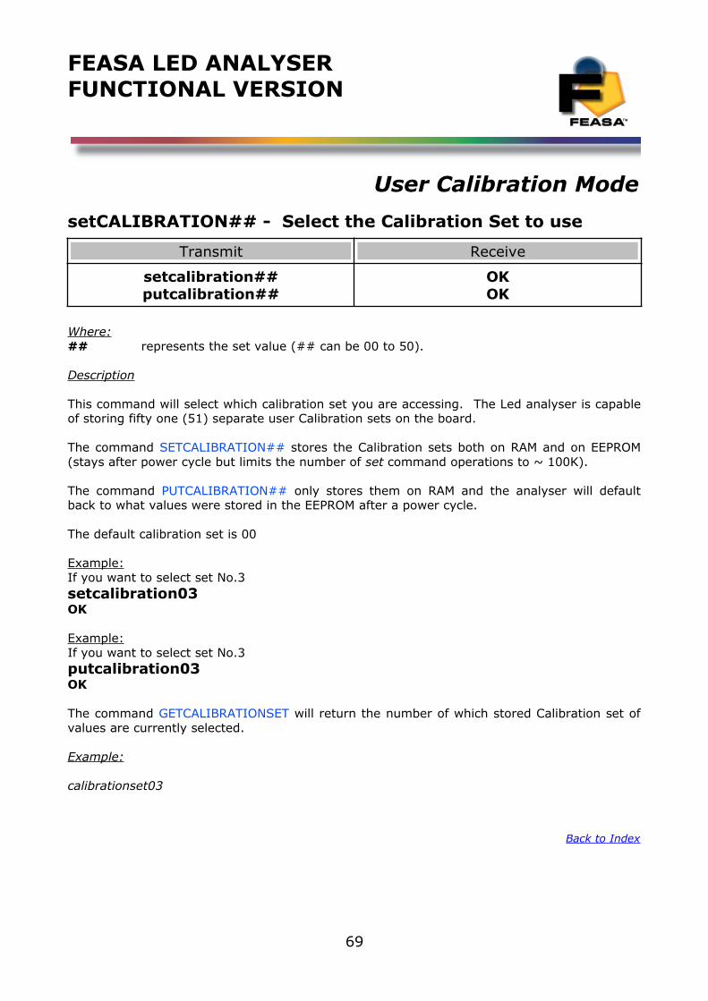
FEASA LED ANALYSERFUNCTIONAL VERSION
User Calibration Mode
setCALIBRATION## - Select the Calibration Set to use
Transmit Receive
setcalibration##putcalibration##
OKOK
Where:## represents the set value (## can be 00 to 50).
Description
This command will select which calibration set you are accessing. The Led analyser is capableof storing fifty one (51) separate user Calibration sets on the board.
The command SETCALIBRATION## stores the Calibration sets both on RAM and on EEPROM(stays after power cycle but limits the number of set command operations to ~ 100K).
The command PUTCALIBRATION## only stores them on RAM and the analyser will defaultback to what values were stored in the EEPROM after a power cycle.
The default calibration set is 00
Example:If you want to select set No.3setcalibration03OK
Example:If you want to select set No.3putcalibration03OK
The command GETCALIBRATIONSET will return the number of which stored Calibration set ofvalues are currently selected.
Example:
calibrationset03
Back to Index
69
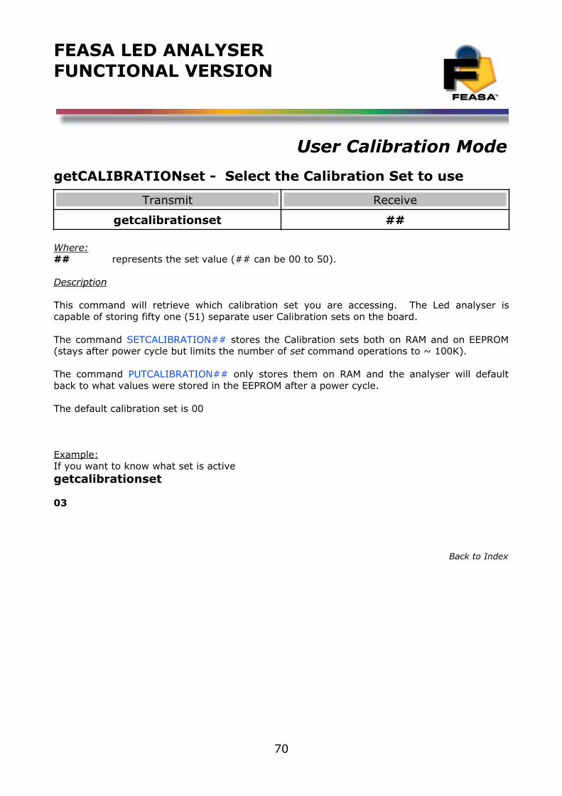
FEASA LED ANALYSERFUNCTIONAL VERSION
User Calibration Mode
getCALIBRATIONset - Select the Calibration Set to use
Transmit Receive
getcalibrationset ##
Where:## represents the set value (## can be 00 to 50).
Description
This command will retrieve which calibration set you are accessing. The Led analyser iscapable of storing fifty one (51) separate user Calibration sets on the board.
The command SETCALIBRATION## stores the Calibration sets both on RAM and on EEPROM(stays after power cycle but limits the number of set command operations to ~ 100K).
The command PUTCALIBRATION## only stores them on RAM and the analyser will defaultback to what values were stored in the EEPROM after a power cycle.
The default calibration set is 00
Example:If you want to know what set is activegetcalibrationset
03
Back to Index
70
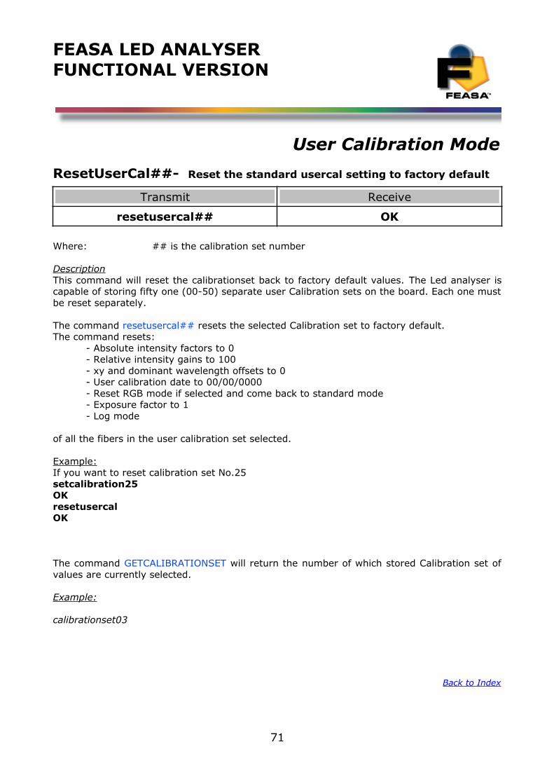
FEASA LED ANALYSERFUNCTIONAL VERSION
User Calibration Mode
ResetUserCal##- Reset the standard usercal setting to factory default
Transmit Receive
resetusercal## OK
Where: ## is the calibration set number
DescriptionThis command will reset the calibrationset back to factory default values. The Led analyser iscapable of storing fifty one (00-50) separate user Calibration sets on the board. Each one mustbe reset separately.
The command resetusercal## resets the selected Calibration set to factory default.The command resets:
- Absolute intensity factors to 0- Relative intensity gains to 100- xy and dominant wavelength offsets to 0- User calibration date to 00/00/0000- Reset RGB mode if selected and come back to standard mode- Exposure factor to 1- Log mode
of all the fibers in the user calibration set selected.
Example:If you want to reset calibration set No.25setcalibration25OKresetusercalOK
The command GETCALIBRATIONSET will return the number of which stored Calibration set ofvalues are currently selected.
Example:
calibrationset03
Back to Index
71
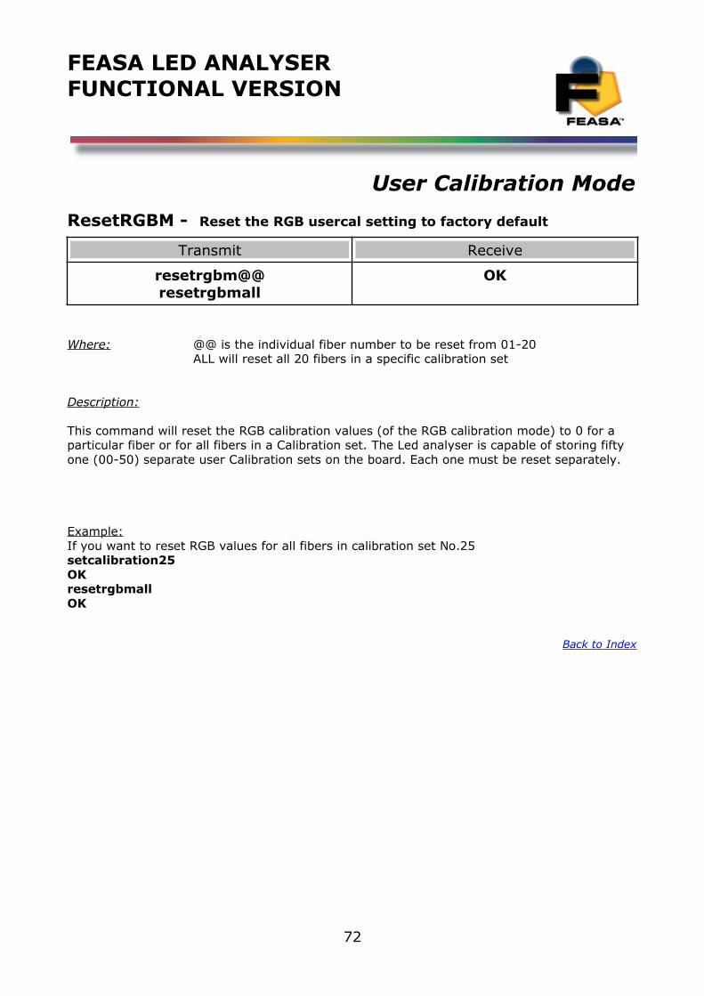
FEASA LED ANALYSERFUNCTIONAL VERSION
User Calibration Mode
ResetRGBM - Reset the RGB usercal setting to factory default
Transmit Receive
resetrgbm@@resetrgbmall
OK
Where: @@ is the individual fiber number to be reset from 01-20ALL will reset all 20 fibers in a specific calibration set
Description:
This command will reset the RGB calibration values (of the RGB calibration mode) to 0 for a particular fiber or for all fibers in a Calibration set. The Led analyser is capable of storing fifty one (00-50) separate user Calibration sets on the board. Each one must be reset separately.
Example:If you want to reset RGB values for all fibers in calibration set No.25setcalibration25OKresetrgbmallOK
Back to Index
72
FEASA LED ANALYSERFUNCTIONAL VERSION
User Calibration Mode
SetCalibrationDateddmmyyyy - Set the user Cal Date
Transmit Receive
Setcalibrationdateddmmyyyy OK
Where:
dd represents the 2 digit Day (01, 02....21, 30)mm represents the 2 digit Month (01, 02...12)yyyy represents a 4 digit Year. (2019)
Description
This command allows the user to input the Calibration Date for the Led Analyser. Thiscommand is used in conjunction with the user calibration set mode.
These dates are stored permanently in memory and can only be changed by using thesetcalibrationdate command again.
The command get calibrationdate will display the current stored Calibration Date setting andcalibration mode settings.
Example:
Set the user Calibration Date for August 1st 2015.setcalibrationdate01082015OK
The commands get calibrationdate or getstatus will display the current stored user CalibrationDate and calibration set mode.
Example:
.
.calibrationset3user calibration date 01/08/2015
Back to Index
73
FEASA LED ANALYSERFUNCTIONAL VERSION
User Calibration Mode
getcalibrationdate Get the Calibration Date set by the user.
Description:
This command will allow the user to interrogate the Led Analyser to return the actual USER Calibration Date in the format dd/mm/yyyy. This is the date set by the user for a specific cal version.
Example:
Connect the Analyser to the Terminal Window and using the getcalibrationdate command, readthe data for that Led. Type the command getcalibrationdate and the analyser will respondwith with the user calibration date in the format dd/mm/yyyy
getcalibrationdate21/01/2015
Back to Index
74

FEASA LED ANALYSERFUNCTIONAL VERSION
User Calibration Mode
User Calibration for RGB Leds
Notes:
The RGB user calibration mode function allows up to 51 (00 to 50) different calibration sets to be simultaneously stored on the Led Analyser. The Analyser is shipped from the factory in set mode 00. setcalibration## (## is 00 to 50) will enable which set you want to work in. While inthis mode you can vary the RGB gains and then save them in that version or set. The date of this user calibration can also be saved using the command setcalibrationdatedd/mm/yyyy. Using the getstatus or getcalibrationset commands the Led Analyser will display which user calibration set you are enabled in and also the date you set it up.
For example if you are testing a board which has 2 different led Colour options you could setcalibration01, adjust your gains or offsets as necessary and proceed to test your version 01 board. setcalibration02 and now adjust you gains or offsets as necessary for your other versionof the board and proceed to test your version 02 of the board. The user calibration date for each set can be saved also.
Feasa provide a program called UserCal on the CD to accomplish this process.
Before doing the RGB calibration, we recommend you select the proper capture mode and range for the Leds you are testing. Standard Capture (C, C1, C2….) mode is recommended for static Leds whereas Capture PWM (eg. c2pwm05) is recommended for RGB LEDs that are pulsing.
Select the relevant Range (Low, Medium High, Super & Ultra) by measuring the final color combination that is going to be measured in the production and also the Blue Led segment (Normally the Blue segment will have the highest Intensity) from the Led under test. Ensure the signal level is > 30 % in order to maximize the repeatability. Use the range which captures these Intensity levels best.
For PWM mode you also need to select the best average factor (00-15) by doing a repeatability analysis on the final colour. The higher the average number, the more repeatable the results will be, However the higher the average the longer the capture time will be required. The Feasa User software has a repeatability test analysis to help you on this task.
When this data is accumulated then proceed to the UserCal Program provided to set the RGB gains.
Back to Index
75
FEASA LED ANALYSERFUNCTIONAL VERSION
External Trigger Mode
External Trigger Method:Functional Led Analysers have a 2 pin input port (Tr) to activate an external trigger capture. Prior to activation the programmer must set the External Trigger Capture mode and the External Trigger Output mode. When set to the correct modes connecting pin 1 to pin 2 will activate a capture and output the relevant readings as selected. No External Voltages are required.
Transmit Receive
Setexternalcapture##Putexternalcapture##
getexternalcapture
See details below
Where ## is as follows:00 Disable Trigger01 Capture1 or C1 (Range Low)02 Capture2 or C2 (Range Medium)03 Capture3 or C3 (Range High)04 Capture4 or C4 (Range Super)05 Capture5 or C5 (Range Ultra)06 Capture or C (Range Auto)
10 Capturepwm or CPWM (Range Auto)11 Capturepwm1 or CPWM112 Capturepwm2 or CPWM213 Capturepwm3 or CPWM314 Capturepwm4 or CPWM415 Capturepwm5 or CPWM5
50 Sequencecapture mode
Transmit Receive
Setexternaloutput####Putexternaloutput####
getexternaloutput
See details below
Where #### is as follows:No output setexternaloutputnoneHSI setexternaloutputhsiXYI setexternaloutputxyiRGBI setexternaloutputrgbiCCTI setexternaloutputcctABSINT setexternaloutputabsintWSI setexternaloutputwsi
Back to Index
76
FEASA LED ANALYSERFUNCTIONAL VERSION
Sequence Capture Mode
Sequence Capture Mode:
Introduction
The Sequence Capture functionality of the LED Analyser allows the user to take multiple captures in rapid succession and store them in the LED Analyser. The results of these captures can be downloaded at any time after the capture sequence has been completed.
This feature is useful when testing LEDs, that when combined, are generating a visual pattern that the user can see. An example of this would be 'soft start' lighting when entering or exitinga vehicle. Another example is when testing the 'visual sweep' on sequential Indicators in vehicles.
The number of captures that can be stored in memory depends on the number of fibers used during the test. If all 20 fibers of a 20 Channel Analyser are used the maximum number of captures that can be stored is 3500. If a single fiber is used then the number of captures increases to 9999.
There are two ways to store commands in the Analyser – one way stores the command in RAMmemory and the second way stores the command in Flash memory. When a command is stored in Flash memory it is not lost when power is removed from the Analyser. When the command is stored in RAM it will be lost when power is removed.
However, there is a limit to the number of write cycles to Flash memory so it is recommended to store commands that are being changed under program control in RAM memory.
Commands that begin with “put” will be stored in RAM while commands that begin with
“set” will be stored in Flash memory.
All commands can use upper or lower case characters.
Back to Index
77
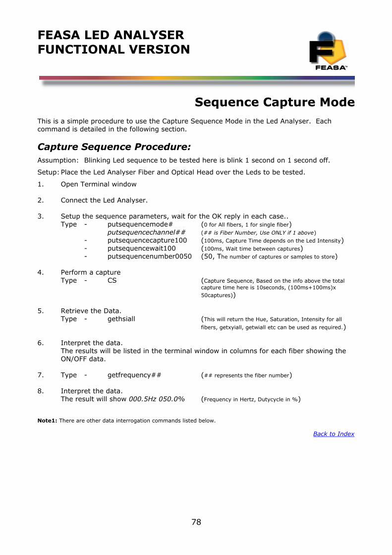
FEASA LED ANALYSERFUNCTIONAL VERSION
Sequence Capture ModeThis is a simple procedure to use the Capture Sequence Mode in the Led Analyser. Each command is detailed in the following section.
Capture Sequence Procedure:Assumption: Blinking Led sequence to be tested here is blink 1 second on 1 second off.
Setup:Place the Led Analyser Fiber and Optical Head over the Leds to be tested.
1. Open Terminal window
2. Connect the Led Analyser.
3. Setup the sequence parameters, wait for the OK reply in each case..Type - putsequencemode# (0 for All fibers, 1 for single fiber)
putsequencechannel## (## is Fiber Number, Use ONLY if 1 above)- putsequencecapture100 (100ms, Capture Time depends on the Led Intensity)- putsequencewait100 (100ms, Wait time between captures)- putsequencenumber0050 (50, The number of captures or samples to store)
4. Perform a captureType - CS (Capture Sequence, Based on the info above the total
capture time here is 10seconds, (100ms+100ms)x 50captures))
5. Retrieve the Data.Type - gethsiall (This will return the Hue, Saturation, Intensity for all
fibers, getxyiall, getwiall etc can be used as required.)
6. Interpret the data.The results will be listed in the terminal window in columns for each fiber showing the ON/OFF data.
7. Type - getfrequency## (## represents the fiber number)
8. Interpret the data.The result will show 000.5Hz 050.0% (Frequency in Hertz, Dutycycle in %)
Note1: There are other data interrogation commands listed below.
Back to Index
78
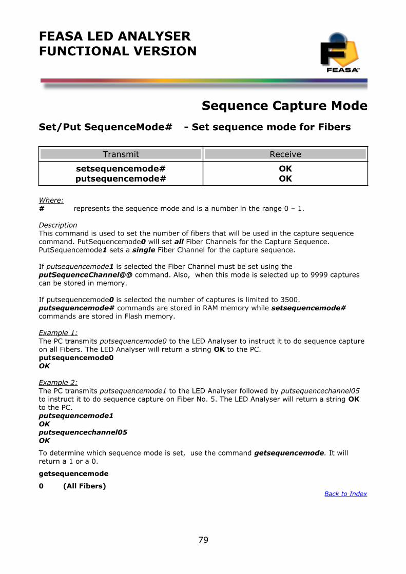
FEASA LED ANALYSERFUNCTIONAL VERSION
Sequence Capture Mode
Set/Put SequenceMode# - Set sequence mode for Fibers
Transmit Receive
setsequencemode#putsequencemode#
OKOK
Where:# represents the sequence mode and is a number in the range 0 – 1.
DescriptionThis command is used to set the number of fibers that will be used in the capture sequence command. PutSequencemode0 will set all Fiber Channels for the Capture Sequence. PutSequencemode1 sets a single Fiber Channel for the capture sequence.
If putsequencemode1 is selected the Fiber Channel must be set using the putSequenceChannel@@ command. Also, when this mode is selected up to 9999 captures can be stored in memory.
If putsequencemode0 is selected the number of captures is limited to 3500.putsequencemode# commands are stored in RAM memory while setsequencemode# commands are stored in Flash memory.
Example 1:The PC transmits putsequencemode0 to the LED Analyser to instruct it to do sequence capture on all Fibers. The LED Analyser will return a string OK to the PC.putsequencemode0OK
Example 2:The PC transmits putsequencemode1 to the LED Analyser followed by putsequencechannel05 to instruct it to do sequence capture on Fiber No. 5. The LED Analyser will return a string OK to the PC.putsequencemode1OKputsequencechannel05OK
To determine which sequence mode is set, use the command getsequencemode. It will return a 1 or a 0.
getsequencemode
0 (All Fibers) Back to Index
79
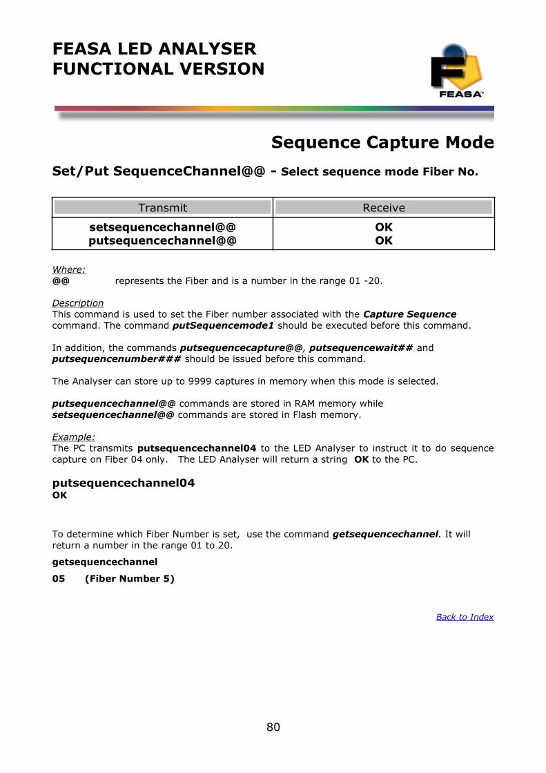
FEASA LED ANALYSERFUNCTIONAL VERSION
Sequence Capture Mode
Set/Put SequenceChannel@@ - Select sequence mode Fiber No.
Transmit Receive
setsequencechannel@@putsequencechannel@@
OKOK
Where:@@ represents the Fiber and is a number in the range 01 -20.
DescriptionThis command is used to set the Fiber number associated with the Capture Sequence command. The command putSequencemode1 should be executed before this command.
In addition, the commands putsequencecapture@@, putsequencewait## and putsequencenumber### should be issued before this command.
The Analyser can store up to 9999 captures in memory when this mode is selected.
putsequencechannel@@ commands are stored in RAM memory while setsequencechannel@@ commands are stored in Flash memory.
Example:The PC transmits putsequencechannel04 to the LED Analyser to instruct it to do sequencecapture on Fiber 04 only. The LED Analyser will return a string OK to the PC.
putsequencechannel04OK
To determine which Fiber Number is set, use the command getsequencechannel. It will return a number in the range 01 to 20.
getsequencechannel
05 (Fiber Number 5)
Back to Index
80
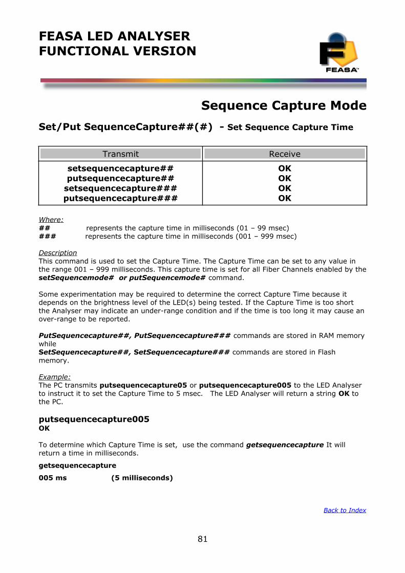
FEASA LED ANALYSERFUNCTIONAL VERSION
Sequence Capture Mode
Set/Put SequenceCapture##(#) - Set Sequence Capture Time
Transmit Receive
setsequencecapture##putsequencecapture##
setsequencecapture###putsequencecapture###
OKOKOKOK
Where:## represents the capture time in milliseconds (01 – 99 msec)### represents the capture time in milliseconds (001 – 999 msec)
DescriptionThis command is used to set the Capture Time. The Capture Time can be set to any value in the range 001 – 999 milliseconds. This capture time is set for all Fiber Channels enabled by thesetSequencemode# or putSequencemode# command.
Some experimentation may be required to determine the correct Capture Time because it depends on the brightness level of the LED(s) being tested. If the Capture Time is too short the Analyser may indicate an under-range condition and if the time is too long it may cause anover-range to be reported.
PutSequencecapture##, PutSequencecapture### commands are stored in RAM memorywhile SetSequencecapture##, SetSequencecapture### commands are stored in Flash memory.
Example:The PC transmits putsequencecapture05 or putsequencecapture005 to the LED Analyser to instruct it to set the Capture Time to 5 msec. The LED Analyser will return a string OK to the PC.
putsequencecapture005OK
To determine which Capture Time is set, use the command getsequencecapture It will return a time in milliseconds.
getsequencecapture
005 ms (5 milliseconds)
Back to Index
81
FEASA LED ANALYSERFUNCTIONAL VERSION
Sequence Capture Mode
Set/Put SequenceWait##(#) - Set Sequence Wait Time
Transmit Receive
setsequencewait##putsequencewait##
setsequencewait###putsequencewait###
OKOKOKOK
Where:## represents the wait time in milliseconds (00 – 99 msec)### represents the wait time in milliseconds (000 – 999 msec)
DescriptionThis command is used to set the Wait time between captures. The Wait time can be set to any value in the range 000 – 999 milliseconds. This Wait time is set for all Fiber Channels enabled by the setSequencemode# or putSequencemode# command.
PutSequencewait##, PutSequencewait### commands are stored in RAM memory while SetSequencewait##, SetSequencewait### commands are stored in Flash memory.
Example:
The PC transmits putsequencewait10 to the LED Analyser to instruct it to set the wait timebetween captures to 10 msec. The LED Analyser will return a string OK to the PC.
putsequencewait10OK
To determine what Wait Time between Sequence Captures is set to, use the command getsequencewait### . It will return a time in milliseconds.
getsequencewait
005 ms (5 milliseconds)
Back to Index
82
FEASA LED ANALYSERFUNCTIONAL VERSION
Sequence Capture Mode
Set/Put SequenceNumber###(#) - Set the Number of Captures
Transmit Receive
putsequencenumber###setsequencenumber###
putsequencenumber####setsequencenumber####
OKOKOKOK
Where:### represents the number of captures to store in the range 000 - 999.#### represents the number of captures to store in the range 000 – 9999.
DescriptionThis command is used to set the number of captures or samples to store. If the setsequencemode# or putsequencemode# is set to 0 then the number of samples that can be stored is 3500.
If the setsequencemode# or putsequencemode# is set to 1 then the number of stored samples increases to 9999.
PutSequencenumber###, PutSequencenumber#### commands are stored in RAM memory while SetSequencenumber###, SetSequencenumber#### commands are stored in Flash memory.
Example:The PC transmits putsequencenumber050 to the LED Analyser to instruct it to store 50 captures when the CaptureSequence command is issued. The LED Analyser will return a string OK to the PC.
putsequencenumber050OK
To determine the number of Sequence Captures stored, use the command getsequencenumber It will return a number in the range 0 - 9999
getsequencenumber
0250 (250 Captures)
Back to Index
83
FEASA LED ANALYSERFUNCTIONAL VERSION
Sequence Capture Mode
Set/Put SequenceThreshold##### - Set the Intensity Threshold
Transmit Receive
putsequencethreshold#####setsequencethreshold#####
OKOK
Where:##### represents the Intensity threshold.
DescriptionThis command is used to set an Intensity threshold so that Intensities above the threshold will be converted to binary 1's and Intensities below the threshold will be converted to binary 0's.
This binary data is used to generate a timing sequence for LEDs that are being switched on and off such as in an automotive Indicator. The timing sequence can be read out using the command getsequencetimes.
PutSequencethreshold##### commands are stored in RAM memory while SetSequencethreshold##### commands are stored in Flash memory.
Example:The PC transmits setsequencethreshold09500 or putsequencethreshold09500 to the LED Analyser to instruct it to treat intensities greater than 9,500 as binary 1 and intensities less than 9,500 as binary 0. The LED Analyser will return a string OK to the PC.
putsequencethreshold09500OK
To determine the minimum Intensity level acceptable as a PASS, use the command getsequencethreshold . It will return an Intensity Value in the range 0 - 99999
getsequencethreshold
9500 (Min Intensity Level 9500)
Back to Index
84
FEASA LED ANALYSERFUNCTIONAL VERSION
Sequence Capture Mode
Set/Put SequenceStartDelay### - Set delay in ms before sequencecapture starts
Transmit Receive
putsequencestartdelay###setsequencestartdelay###
OKOK
Where:### represents the delay in milliseconds before executing a capturesequence and is inthe range 001-999ms.
DescriptionThis command is used to set a delay in milliseconds before the capturesequence starts. This can be useful when using the external trigger mode.
PutSequencestartdelay### commands are stored in RAM memory while SetSequenceStartDelay### commands are stored in Flash memory.
Example:The PC transmits setsequencestartdelay100 or putsequencestartdelay100 to the LED Analyser to instruct it to wait 100ms before starting the capturesequence. The LED Analyser will return a string OK to the PC.
putsequencestartdelay100OK
To determine the delay in milliseconds before the sequence capture is initiated use the command getsequencestartdelay It will return an time in the range 000 - 999ms
getsequencestartdelay
123 ms (Delay before Sequence Capture is 123ms)
Back to Index
85
FEASA LED ANALYSERFUNCTIONAL VERSION
Sequence Capture Mode
CaptureSequence - Start the Captures
Transmit Receive
Capturesequence or CS OK
Description
This command starts the sequence capture function. The LED Analyser will capture and store the Intensity results of each capture up to the number of captures specified by the setsequencenumber### or putsequencenumber### command.
The execution time for this command will depend on the time set for each capture, the wait time between captures and the number of captures.
Example:
The PC transmits capturesequence or cs to the LED Analyser to instruct it to begin capturingdata. The LED Analyser will return a string OK to the PC.
csOK
Back to Index
86
FEASA LED ANALYSERFUNCTIONAL VERSION
Sequence Capture Mode
StoreSequence## - Store the sequence pattern
Transmit Receive
storesequence## OK
Where:
## represents a sequence pattern number and is a value in the range 00 - 20.
Description
This command stores the sequence pattern from the last capturesequence command. The pattern is identified by a number in the range 00 – 20. Up to 21 patterns can be stored.This feature allows the Analyser to identify patterns by comparing them against patterns stored in memory.
The setsequencemode#, setsequencechannel@@, setsequencenumber###, sequencecapture###, sequencenumber, sequencethreshold#####, sequencestartdelay### and sequencewait### commands must be executed before this command takes effect
The StoreSequence## commands are stored in Flash memory.
Example:
The PC transmits storesequence01 to the LED Analyser to instruct it to store the current pattern under the pattern number 01. The LED Analyser will return OK to the PC.
storesequence01OK
Back to Index
87
FEASA LED ANALYSERFUNCTIONAL VERSION
Sequence Capture Mode
IdentifySequence - Identify the current sequence pattern
Transmit Receive
identifysequence ##
Where:
## represents the number of a stored sequence pattern and is a value in the range 00– 20 which compares to the current sequence capture executed.
Description
This command compares the current sequence pattern with a stored list of patterns and identifies it. The pattern is identified by a number in the range 00 – 20. Up to 21 patterns can be stored. This feature allows the Analyser to identify patterns by comparing them against patterns stored in memory.
The setsequencemode#, setsequencechannel@@, setsequencenumber###, sequencecapture###, sequencenumber, sequencethreshold#####, sequencestartdelay### and sequencewait### commands must be executed before this command takes effect. Also, a capturesequence command must be issued before the identifysequence command.
Example:
The PC transmits identifysequence to the LED Analyser to instruct it to identify the currentpattern and return its identity number.
identifysequence04
Back to Index
88
FEASA LED ANALYSERFUNCTIONAL VERSION
Sequence Capture Mode
ResetSequence## - Reset a sequence pattern
Transmit Receive
Resetsequence##resetsequenceall
OK
Where:
## represents the number of a sequence pattern and is a value in the range 00 - 20.all represents the all sequence patterns stores in the Analyser. (max 21 patterns)
Description
This command resets the sequence pattern number ##. The pattern is identified by a number in the range 00 – 20. Up to 21 patterns can be stored.
The sequence pattern ## will be deleted from memory.
Example:
The PC transmits resetsequence01 to the LED Analyser to instruct it to delete sequencepattern 01.
resetsequence01OK
Back to Index
89
FEASA LED ANALYSERFUNCTIONAL VERSION
Sequence Capture Mode
GetSequenceStored## - Get a sequence pattern
Transmit Receive
getsequencestored## OK
Where:## Represents the Sequence pattern stored previously.
Description
The pattern is identified by a number in the range 00 – 20. Up to 21 patterns can be stored.This feature allows the user to recall a stored pattern from memory. If you have stored x different patterns you can recall any one if you know the pattern number.
Example:
getsequencestored05 will recall the sequencecapture number 05.
Back to Index
90
FEASA LED ANALYSERFUNCTIONAL VERSION
Sequence Capture Mode
GetSequence@@ - Get the binary sequence of Intensities
Transmit Receive
getsequence@@ Binary data 0101..
Where:
@@ represents the Fiber number to be interrogated and is a value in the range 01 - 20.
Description
This command returns the Intensity values for Fiber## represented as a binary number. Intensities greater than the threshold value are converted to binary 1's while Intensities less than the threshold are converted to binary 0's.
The threshold value is set by the command putsequencethreshold##### or setsequencethreshold#####. The number of Intensities returned is set by the putsequencenumber### or setsequencenumber### command.
Example:
The PC transmits getsequence01 to the LED Analyser to instruct it to output a binarysequence representing the Intensities that have been captured. The LED Analyser will returna binary sequence to the PC.
getsequence01011..
Back to Index
91
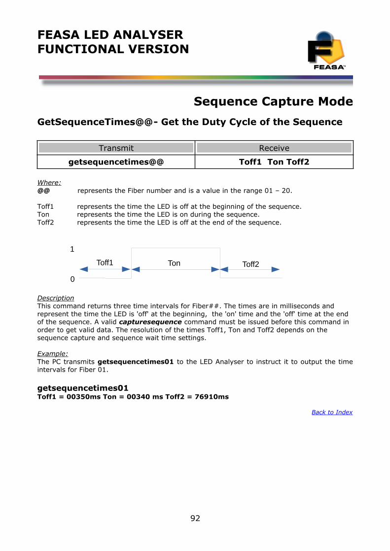
FEASA LED ANALYSERFUNCTIONAL VERSION
Sequence Capture Mode
GetSequenceTimes@@- Get the Duty Cycle of the Sequence
Transmit Receive
getsequencetimes@@ Toff1 Ton Toff2
Where:@@ represents the Fiber number and is a value in the range 01 – 20.
Toff1 represents the time the LED is off at the beginning of the sequence.Ton represents the time the LED is on during the sequence.Toff2 represents the time the LED is off at the end of the sequence.
DescriptionThis command returns three time intervals for Fiber##. The times are in milliseconds and represent the time the LED is 'off' at the beginning, the 'on' time and the 'off' time at the end of the sequence. A valid capturesequence command must be issued before this command in order to get valid data. The resolution of the times Toff1, Ton and Toff2 depends on the sequence capture and sequence wait time settings.
Example:The PC transmits getsequencetimes01 to the LED Analyser to instruct it to output the timeintervals for Fiber 01.
getsequencetimes01Toff1 = 00350ms Ton = 00340 ms Toff2 = 76910ms
Back to Index
92
Toff1 Ton Toff2
1
0
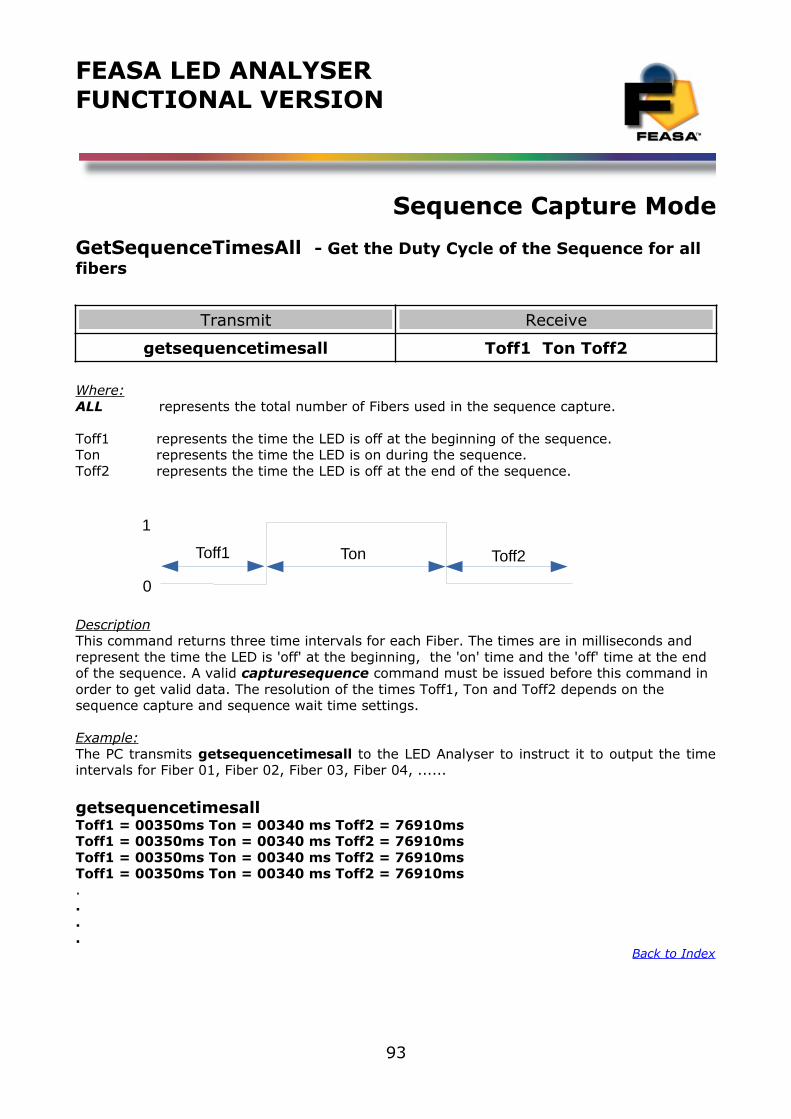
FEASA LED ANALYSERFUNCTIONAL VERSION
Sequence Capture Mode
GetSequenceTimesAll - Get the Duty Cycle of the Sequence for all fibers
Transmit Receive
getsequencetimesall Toff1 Ton Toff2
Where:ALL represents the total number of Fibers used in the sequence capture.
Toff1 represents the time the LED is off at the beginning of the sequence.Ton represents the time the LED is on during the sequence.Toff2 represents the time the LED is off at the end of the sequence.
DescriptionThis command returns three time intervals for each Fiber. The times are in milliseconds and represent the time the LED is 'off' at the beginning, the 'on' time and the 'off' time at the end of the sequence. A valid capturesequence command must be issued before this command in order to get valid data. The resolution of the times Toff1, Ton and Toff2 depends on the sequence capture and sequence wait time settings.
Example:The PC transmits getsequencetimesall to the LED Analyser to instruct it to output the timeintervals for Fiber 01, Fiber 02, Fiber 03, Fiber 04, ......
getsequencetimesallToff1 = 00350ms Ton = 00340 ms Toff2 = 76910msToff1 = 00350ms Ton = 00340 ms Toff2 = 76910msToff1 = 00350ms Ton = 00340 ms Toff2 = 76910msToff1 = 00350ms Ton = 00340 ms Toff2 = 76910ms....
Back to Index
93
Toff1 Ton Toff2
1
0
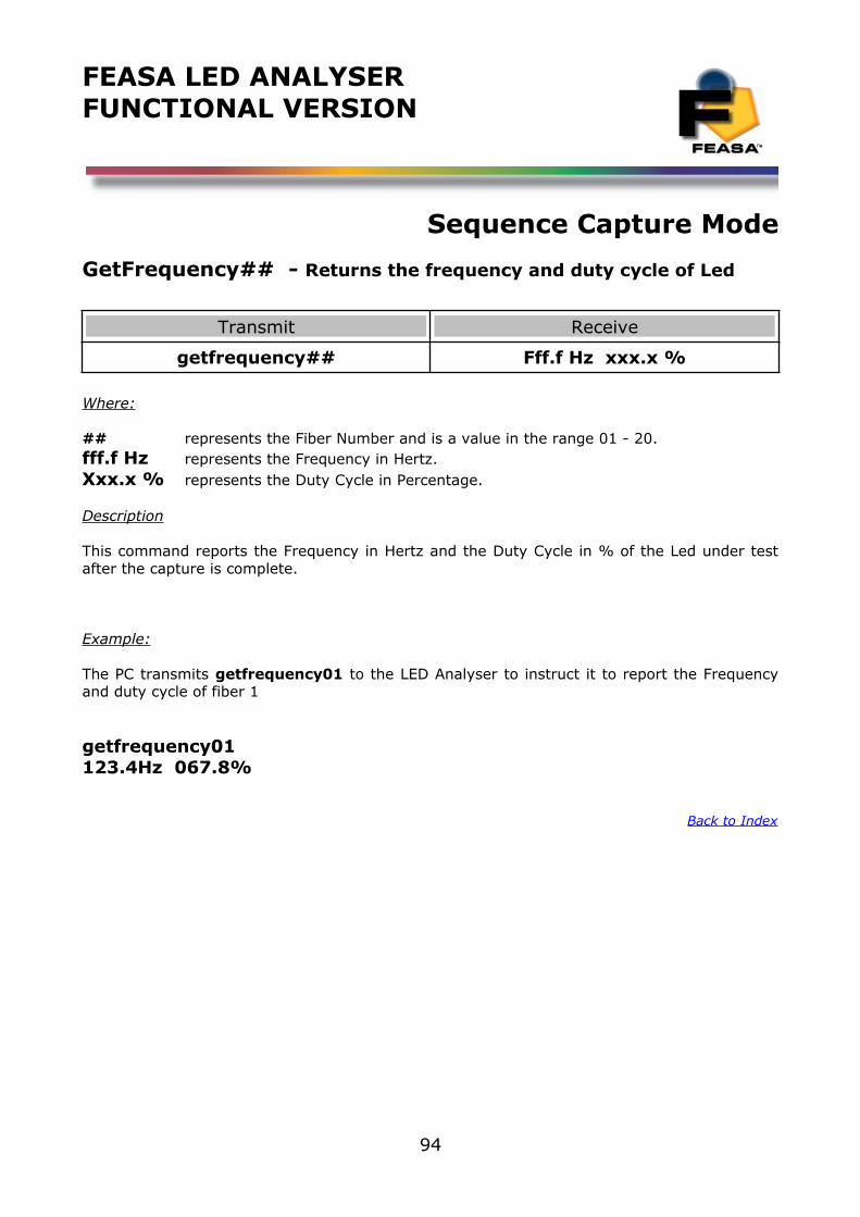
FEASA LED ANALYSERFUNCTIONAL VERSION
Sequence Capture Mode
GetFrequency## - Returns the frequency and duty cycle of Led
Transmit Receive
getfrequency## Fff.f Hz xxx.x %
Where:
## represents the Fiber Number and is a value in the range 01 - 20.fff.f Hz represents the Frequency in Hertz.Xxx.x % represents the Duty Cycle in Percentage.
Description
This command reports the Frequency in Hertz and the Duty Cycle in % of the Led under testafter the capture is complete.
Example:
The PC transmits getfrequency01 to the LED Analyser to instruct it to report the Frequencyand duty cycle of fiber 1
getfrequency01123.4Hz 067.8%
Back to Index
94
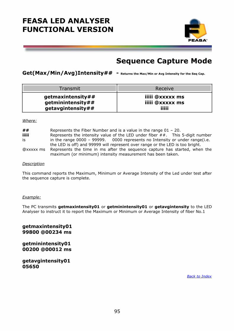
FEASA LED ANALYSERFUNCTIONAL VERSION
Sequence Capture Mode
Get(Max/Min/Avg)Intensity## - Returns the Max/Min or Avg Intensity for the Seq Cap.
Transmit Receive
getmaxintensity##getminintensity##getavgintensity##
iiiii @xxxxx msiiiii @xxxxx ms
iiiii
Where:
## Represents the Fiber Number and is a value in the range 01 – 20.iiiii Represents the intensity value of the LED under fiber ##. This 5-digit numberis in the range 0000 – 99999. 0000 represents no Intensity or under range(i.e.
the LED is off) and 99999 will represent over range or the LED is too bright.@xxxxx ms Represents the time in ms after the sequence capture has started, when the
maximum (or minimum) intensity measurement has been taken.
Description
This command reports the Maximum, Minimum or Average Intensity of the Led under test afterthe sequence capture is complete.
Example:
The PC transmits getmaxintensity01 or getminintensity01 or getavgintensity to the LEDAnalyser to instruct it to report the Maximum or Minimum or Average Intensity of fiber No.1
getmaxintensity0199800 @00234 ms
getminintensity0100200 @00012 ms
getavgintensity0105650
Back to Index
95
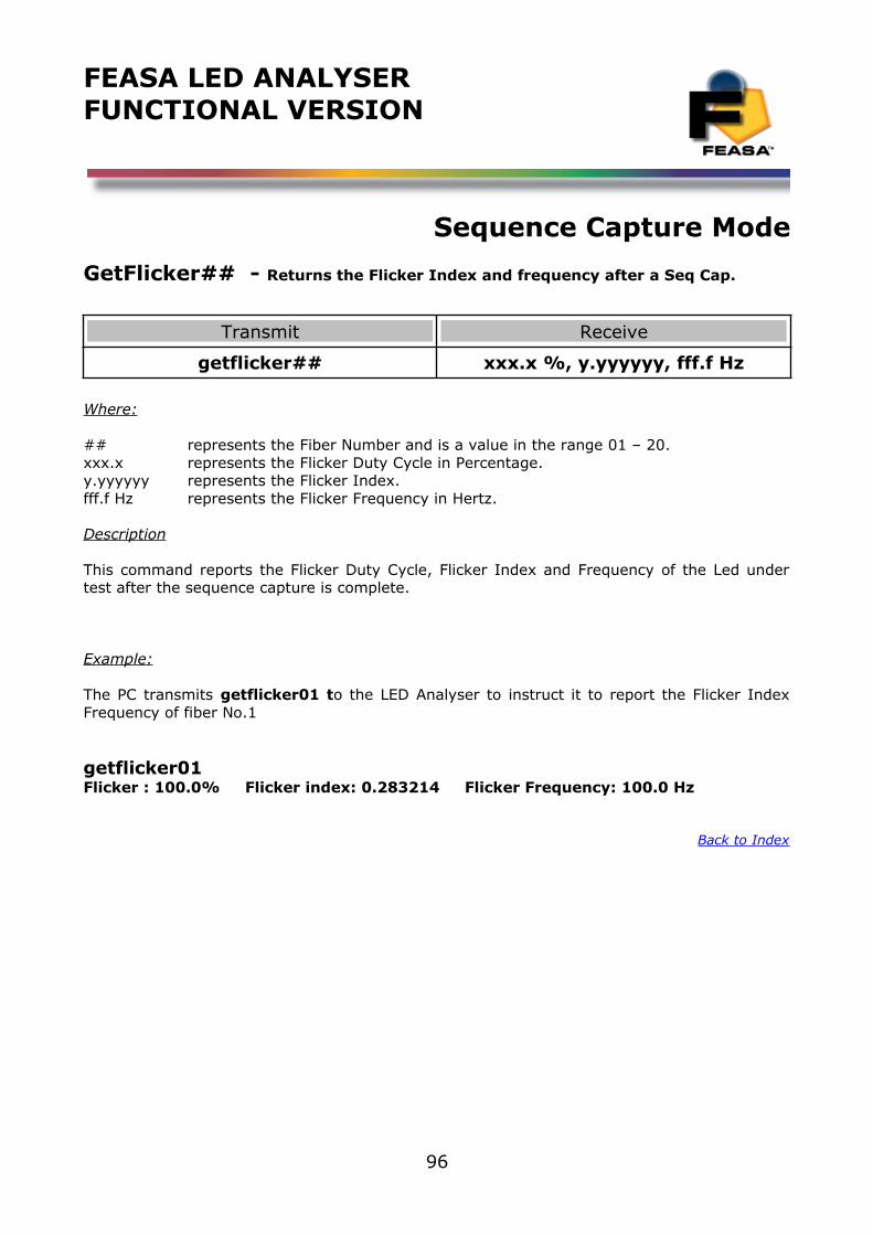
FEASA LED ANALYSERFUNCTIONAL VERSION
Sequence Capture Mode
GetFlicker## - Returns the Flicker Index and frequency after a Seq Cap.
Transmit Receive
getflicker## xxx.x %, y.yyyyyy, fff.f Hz
Where:
## represents the Fiber Number and is a value in the range 01 – 20.xxx.x represents the Flicker Duty Cycle in Percentage.y.yyyyyy represents the Flicker Index.fff.f Hz represents the Flicker Frequency in Hertz.
Description
This command reports the Flicker Duty Cycle, Flicker Index and Frequency of the Led undertest after the sequence capture is complete.
Example:
The PC transmits getflicker01 to the LED Analyser to instruct it to report the Flicker IndexFrequency of fiber No.1
getflicker01Flicker : 100.0% Flicker index: 0.283214 Flicker Frequency: 100.0 Hz
Back to Index
96
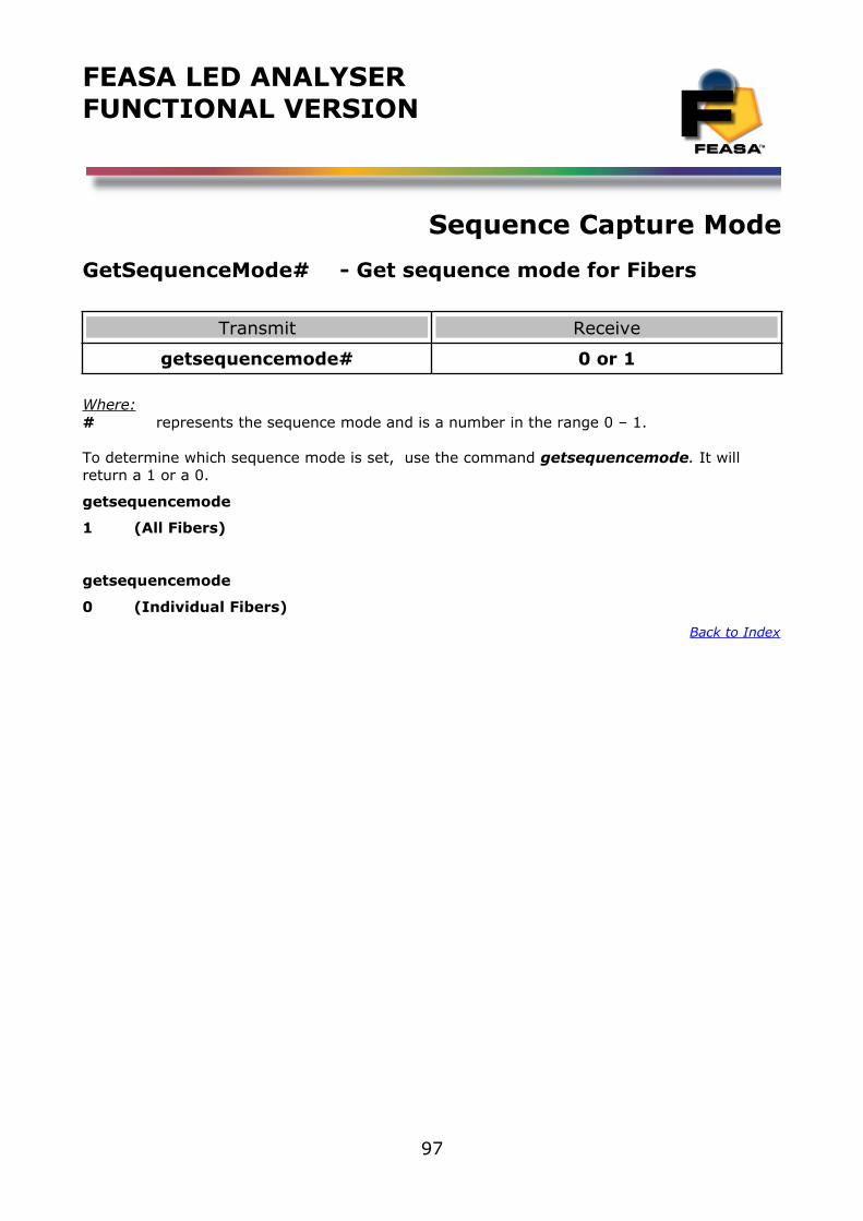
FEASA LED ANALYSERFUNCTIONAL VERSION
Sequence Capture Mode
GetSequenceMode# - Get sequence mode for Fibers
Transmit Receive
getsequencemode# 0 or 1
Where:# represents the sequence mode and is a number in the range 0 – 1.
To determine which sequence mode is set, use the command getsequencemode. It will return a 1 or a 0.
getsequencemode
1 (All Fibers)
getsequencemode
0 (Individual Fibers)
Back to Index
97
FEASA LED ANALYSERFUNCTIONAL VERSION
Sequence Capture Mode
GetSequenceChannel - Select sequence mode Fiber No.
Transmit Receive
getsequencechannel 01 to 20
Where:01 – 20 represents the Fiber Number and is in the range 01 -20.
To determine which Fiber Number is set, use the command getsequencechannel. It will return a number in the range 01 to 20.
getsequencechannel
05 (Fiber Number 5)
Back to Index
98
FEASA LED ANALYSERFUNCTIONAL VERSION
Sequence Capture Mode
GetSequenceCapture - Get Sequence Capture Time
Transmit Receive
getsequencecapture xx ms or xxx ms
Where:## represents the capture time in milliseconds (01 – 99)### represents the capture time in milliseconds (001 – 999)
To determine which Capture Time is set, use the command getsequencecapture It will return a time in milliseconds.
getsequencecapture
005 ms (5 milliseconds)
Back to Index
99
FEASA LED ANALYSERFUNCTIONAL VERSION
Sequence Capture Mode
GetSequenceWait - Get Sequence Wait Time
Transmit Receive
getsequencewait xx ms or xxx ms
Where:xx represents the wait time in milliseconds (00 – 99)xxx represents the wait time in milliseconds (000 – 999)
To determine what Wait Time between Sequence Captures is set to, use the command getsequencewait . It will return a time in milliseconds.
getsequencewait
005 ms (5 milliseconds)
Back to Index
100
FEASA LED ANALYSERFUNCTIONAL VERSION
Sequence Capture Mode
GetSequenceNumber - Get the Number of Captures
Transmit Receive
getsequencenumber xxxx
Where:xxxx represents the number of captures stored.
To determine the number of Sequence Captures stored, use the command getsequencenumber It will return a number in the range 0 - 9999
getsequencenumber
0250 (250 Captures)
Back to Index
101
FEASA LED ANALYSERFUNCTIONAL VERSION
Sequence Capture Mode
GetSequenceThreshold - Get the Intensity Threshold
Transmit Receive
getsequencethreshold xxxxx
Where:xxxxx represents the Intensity threshold.
To determine the minimum Intensity level acceptable as a PASS, use the command getsequencethreshold . It will return an Intensity Value in the range 0 - 99999
getsequencethreshold
9500 (Min Intensity Level 9500)
Back to Index
102

FEASA LED ANALYSERFUNCTIONAL VERSION
Sequence Capture Mode
GetSequenceStartDelay - Get the delay before the CS command
Transmit Receive
getsequencestartdelay xxx
Where:xxx represents the delay in milliseconds
To determine the delay in milliseconds before the sequence capture is initiated use the command getsequencestartdelay It will return a time in the range 000 - 999ms
getsequencestartdelay
123 ms (Delay before Sequence Capture is 123ms)
Back to Index
103
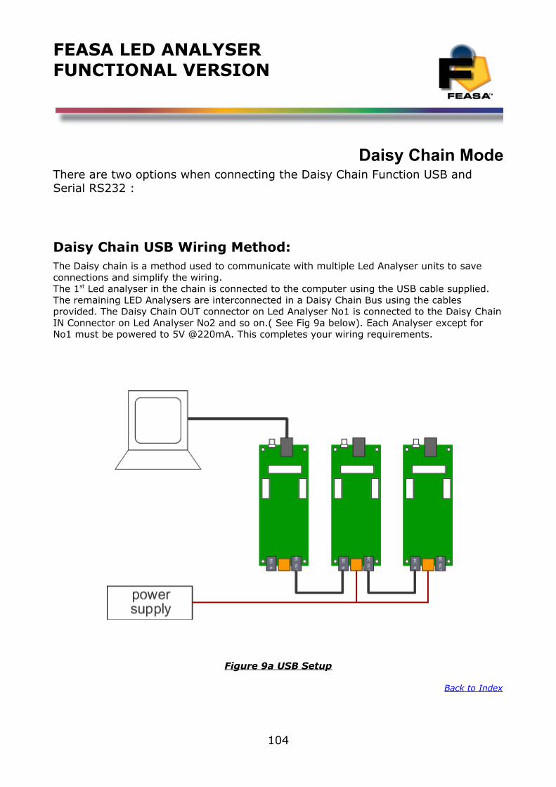
FEASA LED ANALYSERFUNCTIONAL VERSION
Daisy Chain ModeThere are two options when connecting the Daisy Chain Function USB and Serial RS232 :
Daisy Chain USB Wiring Method:The Daisy chain is a method used to communicate with multiple Led Analyser units to save connections and simplify the wiring.The 1st Led analyser in the chain is connected to the computer using the USB cable supplied. The remaining LED Analysers are interconnected in a Daisy Chain Bus using the cables provided. The Daisy Chain OUT connector on Led Analyser No1 is connected to the Daisy ChainIN Connector on Led Analyser No2 and so on.( See Fig 9a below). Each Analyser except for No1 must be powered to 5V @220mA. This completes your wiring requirements.
Figure 9a USB Setup
Back to Index
104
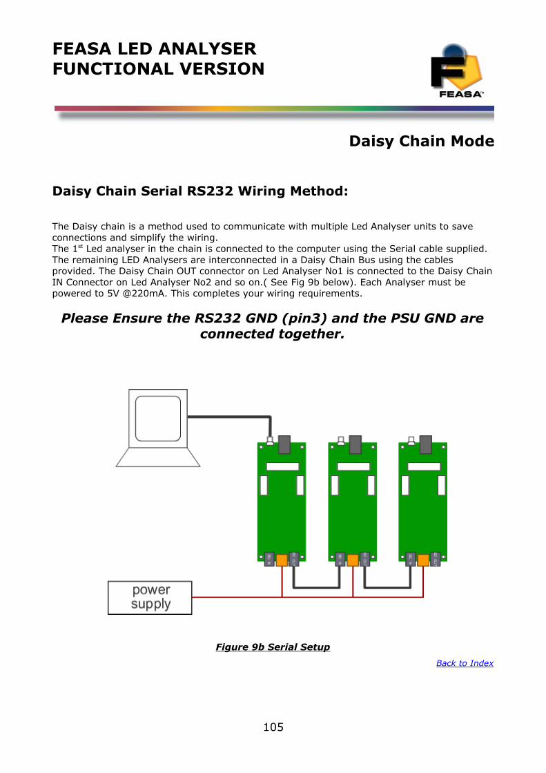
FEASA LED ANALYSERFUNCTIONAL VERSION
Daisy Chain Mode
Daisy Chain Serial RS232 Wiring Method:
The Daisy chain is a method used to communicate with multiple Led Analyser units to save connections and simplify the wiring.The 1st Led analyser in the chain is connected to the computer using the Serial cable supplied. The remaining LED Analysers are interconnected in a Daisy Chain Bus using the cables provided. The Daisy Chain OUT connector on Led Analyser No1 is connected to the Daisy ChainIN Connector on Led Analyser No2 and so on.( See Fig 9b below). Each Analyser must be powered to 5V @220mA. This completes your wiring requirements.
Please Ensure the RS232 GND (pin3) and the PSU GND areconnected together.
Figure 9b Serial Setup
Back to Index
105

FEASA LED ANALYSERFUNCTIONAL VERSION
Daisy Chain Mode
Daisy Chain Baudrate: The default Port settings of the Analysers are 57,600, 8 Data bits, 1 Stop bit and No Parity. If an incompatible baud rates are selected the Analyser will not respond. Please disconnect theAnalysers from the Daisy Chain and reconnect each Analyser in turn using USB or Serial RS232port and set the required baudrate. All baudrates must be the same for communicationpurposes. A correct baud rate selected will remain stored in memory even after power off. The command getbaud will return the set baud rate. It can also be seen on the commentsection of the Feasa terminal window.
Test times are improved by increasing the baudrate from the default to higher values and thiscan be further enhanced by decreasing the latency (windows default 16) to latency of 1. Referto the App Note in the documentation folder of the CD to carry out this.
The LED Analyser connected to the computer receives a command and this command isreceived by all the other LED Analysers through the Daisy Chain Bus. All Analysers in the chainare active but only the selected LED Analyser is active to give result Data. All responsesreceived by the Computer will be from this active LED Analyser.
Daisy Chain Identification: Each LED Analyser is identified using a unique 4-character Serial Number. This Serial Numberis fixed to each Analyser or can be read out using the getSerial command.
Feasa provides a Terminal Program on the CD for the customers use. When you connectyour 1st analyser the terminal program will detect which port you are connected to. At this timeyou have the option of connecting to the Standalone option or the Daisy Chain option from thedrop down box. If you select the Daisy Chain option you will be asked for the serial Number ofthe 1st analyser in your chain.
There are a number of commands which are used to control the Analysers in the Daisy Chain.These commands are described on the following pages.
Back to Index
106
FEASA LED ANALYSERFUNCTIONAL VERSION
Daisy Chain Mode
BusFree - Deactivate any active Analysers
Transmit Receive
busfree OK
Description
This command is used to deactivate any active Analysers on the Daisy Chain Bus. This willfree the Bus to allow an Analyser to be made active. This command should be issued at thestart of a sequence. It is the responsibility of the Controlling Computer to issue commandsand monitor the responses. If an Analyser does not respond within 500mSec then theControlling Computer should issue a new BusFree command and report an error.
The Analyser connected to the computer will operate as a standalone unit after the commandis issued.
Example:
The PC transmits busfree to free up the Daisy Chain Bus.
busfreeOK
Back to Index
107
FEASA LED ANALYSERFUNCTIONAL VERSION
Daisy Chain Mode
BusGet####- Activate a LED Analyser
Transmit Receive
busget#### OK
Where:
#### represents the Serial Number of the Analyser.
Description
This command will activate the LED Analyser with the specified Serial Number.This command should be preceded by a BusFree command. All the Capture, Set, Get, etccommands can now be used with the active Analyser in the chain.
It is the responsibility of the Controlling Computer to issue commands and monitor theresponses. If an Analyser does not respond within 500mSec then the Controlling Computershould issue a new BusFree command and report an error.
Example:
The PC transmits BusGet#### to the Master LED Analyser to instruct it to activate the LEDAnalyser with Serial Number ####.
busgetF044OK
Back to Index
108
FEASA LED ANALYSERFUNCTIONAL VERSION
Daisy Chain Mode
BusC - Initiate Capture for all LED Analyser's
Transmit Receive
busc OK
Description
This command will cause all LED Analysers in the Daisy Chain to initiate a capture sequenceusing the Automatic Range Mode. To specify a Range manually see the command BusC# onthe next page.
After the capture cycle use the command BusGet#### to activate a specific LED Analyser.All the standard commands can then be used to read back the LED Test data.
Example:
The PC transmits busc to instruct all LED Analysers in the Daisy Chain to initiate a Capturecycle.
buscOK
Back to Index
109
FEASA LED ANALYSERFUNCTIONAL VERSION
Daisy Chain Mode
BusC# - Initiate Capture for all LED Analyser's
Transmit Receive
busc# OK
Where:
# represents the ranges 1, 2, 3, 4, 5.
The LED brightness level for each range is as follows:-
Range 1 = LowRange 2 = MediumRange 3 = HighRange 4 = SuperRange 5 = Ultra
DescriptionThis command uses a pre-selected exposure time designated Range1, Range2 etc. For lowlight or dim LED's use Range 1 and for brighter LED's use higher ranges. The higher rangeslead to faster test times because the exposure time is shorter.This command should be preceded by a BusFree command.
This command instructs all LED Analyser's in the Daisy Chain to capture and store the Colourand Intensity of all the LED's positioned under the fibers using a fixed range. The range setting must be specified. The data is stored until the power is removed or anothercapture command is issued. When completed the Analyser will transmit the character OK onthe receive line to the transmitting device (i.e. the PC).Example:
The PC transmits busc# to instruct all LED Analysers in the Daisy Chain to initiate a Capturecycle.
busc2OK
Back to Index
110
FEASA LED ANALYSERFUNCTIONAL VERSION
Daisy Chain ModeBusC#pwm@@ - Store PWM LED Data for a specific Range
Transmit Receive
Busc#pwmBusc#pwm@@
OKOK
Where:
# represents the exposure Range 1 – 5.@@ represents an averaging factor in the range 1 - 15.@@ If the @@ digits are omitted then a default setting of 07 is used.
Description
This command allows the User to specify the exposure range # and an averaging factor @@when testing PWM LED's. Select the exposure range # (1-5) to match the Intensity of theLED's. The Analyser tests these LED's by taking a number of readings and averaging theresults. A larger Averaging factor will lead to more stable results but increased Test Times.The averaging factor @@ is a number in the range 1-15. If this number is omitted from thecommand the default value is 07.
This command instructs the LED Analyser to read and store the Colour and Intensity of all theLED's positioned under the fibers. The data is stored until the power is removed or anothercapture command is issued. When completed the Analyser will transmit the character OK onthe receive line to the transmitting device (i.e. the PC).
busc1pwm10OK
There are 5 manual capture ranges each with an intensity output range of 0 to99,999. Feasa recommends that the UUT readings should be in the 55K to 85K rangefor the best stability.
Back to Index
111
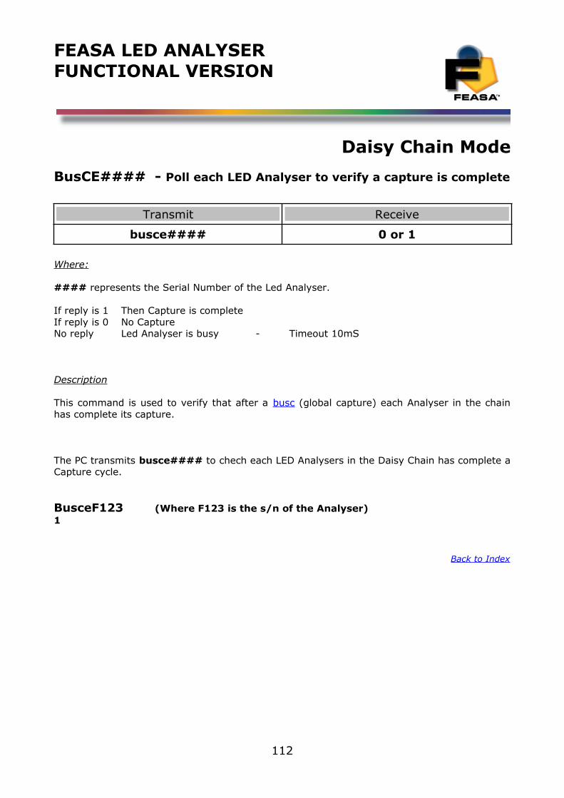
FEASA LED ANALYSERFUNCTIONAL VERSION
Daisy Chain Mode
BusCE#### - Poll each LED Analyser to verify a capture is complete
Transmit Receive
busce#### 0 or 1
Where:
#### represents the Serial Number of the Led Analyser.
If reply is 1 Then Capture is completeIf reply is 0 No Capture No reply Led Analyser is busy - Timeout 10mS
Description
This command is used to verify that after a busc (global capture) each Analyser in the chainhas complete its capture.
The PC transmits busce#### to chech each LED Analysers in the Daisy Chain has complete aCapture cycle.
BusceF123 (Where F123 is the s/n of the Analyser)1
Back to Index
112

FEASA LED ANALYSERFUNCTIONAL VERSION
Daisy Chain Mode
Ports Description and Wiring.
Figure 10
The Daisy Chain Connectors are shown on the right-hand side of figure 10.The D_OUT connector is connected to the D_IN connector of the next Analyser in the chain.
The Power Connector is used to supply +5V DC to each Analyser in the chain.Allow 220mA @5V for each Analyser and ensure the wiring is adequate to supply the current without incurring large voltage drops. For reliable operation it is necessary to have 5V at the Power Connector of each Analyser. Do not exceed 6V for a prolonged period as this will damage the Analyser.
Back to Index
113
D_OUT
D_IN123
123
Power 0V5V
USB
Serial
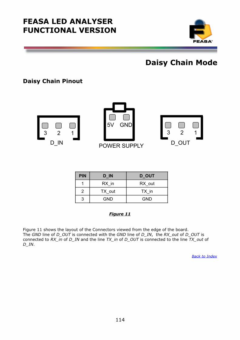
FEASA LED ANALYSERFUNCTIONAL VERSION
Daisy Chain Mode
Daisy Chain Pinout
PIN D_IN D_OUT
1 RX_in RX_out
2 TX_out TX_in
3 GND GND
Figure 11
Figure 11 shows the layout of the Connectors viewed from the edge of the board. The GND line of D_OUT is connected with the GND line of D_IN, the RX_out of D_OUT is connected to RX_in of D_IN and the line TX_in of D_OUT is connected to the line TX_out of D_IN.
Back to Index
114
123
D_IN
123
D_OUT
GND5V
POWER SUPPLY
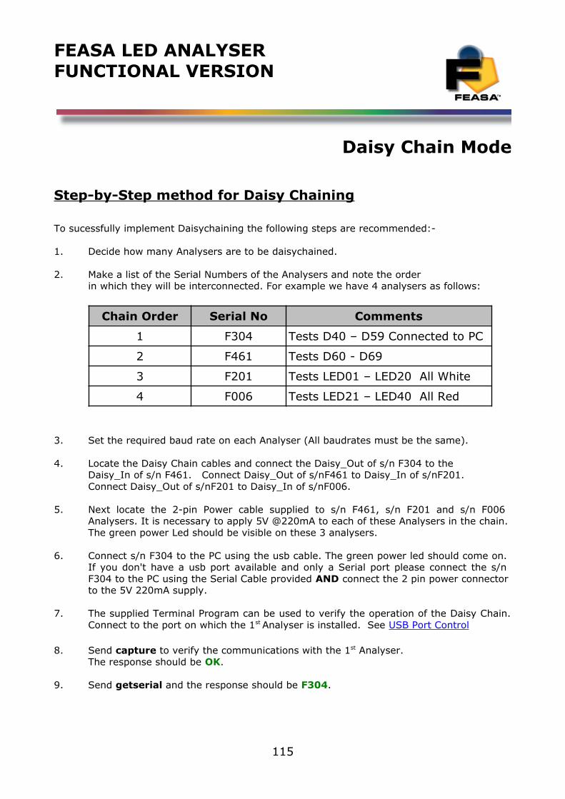
FEASA LED ANALYSERFUNCTIONAL VERSION
Daisy Chain Mode
Step-by-Step method for Daisy Chaining
To sucessfully implement Daisychaining the following steps are recommended:-
1. Decide how many Analysers are to be daisychained.
2. Make a list of the Serial Numbers of the Analysers and note the orderin which they will be interconnected. For example we have 4 analysers as follows:
Chain Order Serial No Comments
1 F304 Tests D40 – D59 Connected to PC
2 F461 Tests D60 - D69
3 F201 Tests LED01 – LED20 All White
4 F006 Tests LED21 – LED40 All Red
3. Set the required baud rate on each Analyser (All baudrates must be the same).
4. Locate the Daisy Chain cables and connect the Daisy_Out of s/n F304 to theDaisy_In of s/n F461. Connect Daisy_Out of s/nF461 to Daisy_In of s/nF201.Connect Daisy_Out of s/nF201 to Daisy_In of s/nF006.
5. Next locate the 2-pin Power cable supplied to s/n F461, s/n F201 and s/n F006 Analysers. It is necessary to apply 5V @220mA to each of these Analysers in the chain. The green power Led should be visible on these 3 analysers.
6. Connect s/n F304 to the PC using the usb cable. The green power led should come on. If you don't have a usb port available and only a Serial port please connect the s/n F304 to the PC using the Serial Cable provided AND connect the 2 pin power connector to the 5V 220mA supply.
7. The supplied Terminal Program can be used to verify the operation of the Daisy Chain.Connect to the port on which the 1st Analyser is installed. See USB Port Control
8. Send capture to verify the communications with the 1st Analyser.The response should be OK.
9. Send getserial and the response should be F304.
115
FEASA LED ANALYSERFUNCTIONAL VERSION
Daisy Chain Mode
10. To connect to Analyser 2 (s/n F461) send:-
busfreeOK Response from the AnalyserbusgetF461OK Response from the Analyser
The host computer is now connected to Analyser 2 (s/n F461).This can be verified by requesting the Serial Number:-
getserialF461 Response from the Analyser
All the LED Analyser commands can now be directed to Analyser 2.
11. To connect to Analyser 3 (s/n F201) send the following:-
busfreeOK Response from the AnalyserbusgetF201OK Response from the Analyser
12. It is possible to instruct all Analysers in the chain to capture LED data simultaneously. This makes programming easier and saves time. There are six capture commands in total but only one can be used at a time. The commands are busc, busc1, busc2, busc3, busc4 and busc5. Busc uses the automatic capture range whereas busc1 – busc5 use pre-selected manual ranges.
13. If you are have difficulty reading from Analysers at the end of your chain please verify your voltage to each of these units is 5V.
Back to Index
116
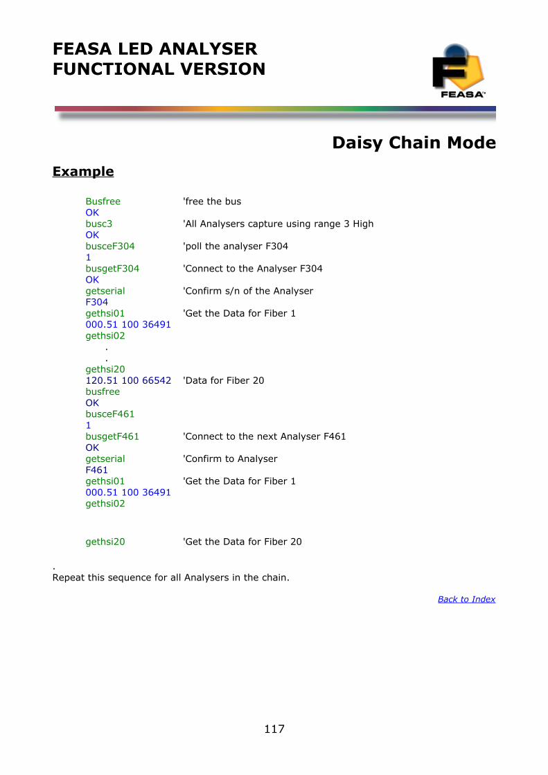
FEASA LED ANALYSERFUNCTIONAL VERSION
Daisy Chain Mode
Example
Busfree 'free the busOKbusc3 'All Analysers capture using range 3 HighOKbusceF304 'poll the analyser F3041busgetF304 'Connect to the Analyser F304OKgetserial 'Confirm s/n of the AnalyserF304gethsi01 'Get the Data for Fiber 1000.51 100 36491 gethsi02 . .gethsi20120.51 100 66542 'Data for Fiber 20busfreeOKbusceF4611busgetF461 'Connect to the next Analyser F461OKgetserial 'Confirm to AnalyserF461gethsi01 'Get the Data for Fiber 1000.51 100 36491 gethsi02
gethsi20 'Get the Data for Fiber 20
.Repeat this sequence for all Analysers in the chain.
Back to Index
117
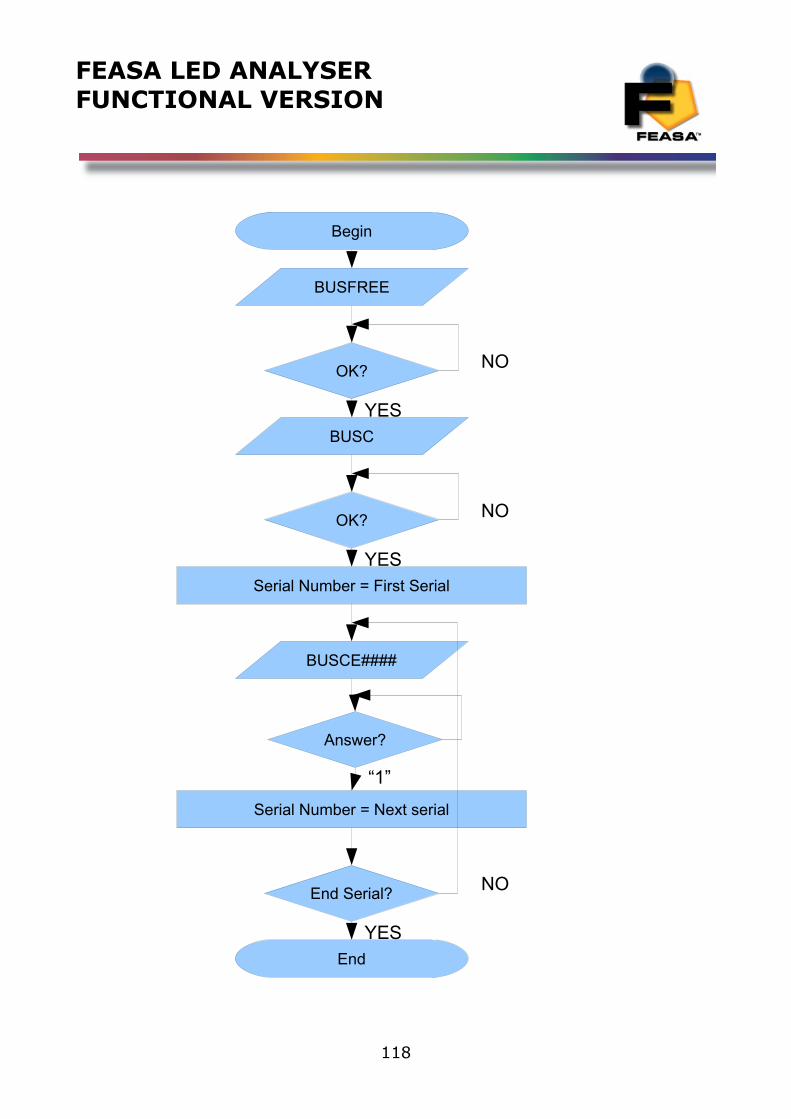
FEASA LED ANALYSERFUNCTIONAL VERSION
118
Begin
OK?
Serial Number = First Serial
BUSFREE
BUSC
OK?
BUSCE####
Answer?
Serial Number = Next serial
End Serial?
End
NO
YES
“1”
NO
NO
YES
YES
FEASA LED ANALYSERFUNCTIONAL VERSION
Step-by-Step approach to Testing a LED
Standard Capture Mode
To Test the Colour and Intensity of up to 20 LEDs simultaneously carry out the following:
1. Ensure that the LEDs to be Tested are turned on and that the fibers are centered overthe LEDs.
2. To Test the Colour and Intensity in RGB first send the command capture to the LEDAnalyser. The LED Analyser will return the characters OK indicating that the Colour and Intensitydata for the LEDs has been stored in the internal memory.
3. Transmit the command getrgbi01 to retrieve the results for Fiber 1. Any fiber can bequeried by sending the command getrgbixx to the LED Analyser, where xx is the fiber number inthe range 01 to 20. The LED Analyser will return the results in the format rrr ggg bbb iiiiiEwhere rrr, ggg and bbb are the red, green and blue components of the light in decimal formatin the range 000 to 255. The iiiii value indicates the intensity value of the light in the range00000 to 99,999.
4. Alternatively, the Led Analyser may also be queried to retrieve the Hue, Saturation andIntensity results for the LEDs under test. After step 2 send the command gethsixx to the LEDAnalyser where xx is the fiber number. The LED Analyser will return the results for that fiber inthe format hhh.hh sss iiiiiE where hhh.hh is the Hue, sss is the Saturation(whiteness) and iiiiiare the Intensity results for that Fiber.
5. An Intensity value of 0 will indicate that the LED under test is not bright enough. Tocompensate for this move the fiber closer to the LED or increase the LED intensity. An Intensityvalue of 99,999 will indicate that the LED is too bright and the LED Analyser has an over-rangecondition. In this case increase the distance of the LED to the Fiber or decrease the LED Intensity.
6. In general, try to keep the Intensity less than 80,000 and greater than 20,000.
Back to Index
119
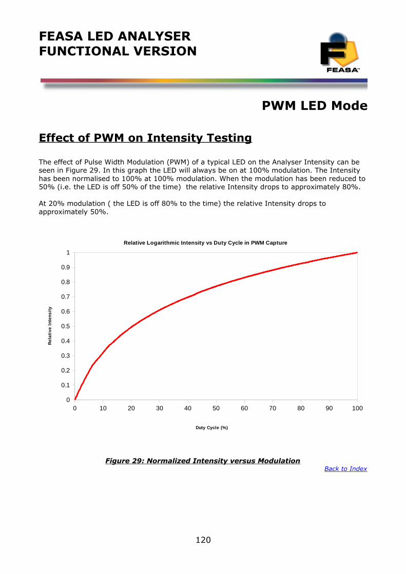
FEASA LED ANALYSERFUNCTIONAL VERSION
PWM LED Mode
Effect of PWM on Intensity Testing
The effect of Pulse Width Modulation (PWM) of a typical LED on the Analyser Intensity can be seen in Figure 29. In this graph the LED will always be on at 100% modulation. The Intensity has been normalised to 100% at 100% modulation. When the modulation has been reduced to50% (i.e. the LED is off 50% of the time) the relative Intensity drops to approximately 80%.
At 20% modulation ( the LED is off 80% to the time) the relative Intensity drops to approximately 50%.
0 10 20 30 40 50 60 70 80 90 1000
0.1
0.2
0.3
0.4
0.5
0.6
0.7
0.8
0.9
1
Relative Logarithmic Intensity vs Duty Cycle in PWM Capture
Duty Cycle (%)
Re
lati
ve
In
ten
sit
y
Figure 29: Normalized Intensity versus ModulationBack to Index
120
FEASA LED ANALYSERFUNCTIONAL VERSION
Step-by-Step approach to Testing a PWM LED
PWM LED Mode
To test PWM LEDs use the following commands on the LED Analyser for Fiber 1:
1. Decide how many readings are required to test the PWM LED's. The Analyser can be programmed to take between 1 and 15 readings. The more readings that are taken the greater the stability of the results.
2. Send the command CAPTURE#PWM@@, where @@ is the number of readings to takeand # is the Intensity range. The LED Analyser will capture and store the Colour,Saturation and Intensity data for all fibers. The LED Analyser will respond with theCharacters OK indicating that the command has been completed.
3. To read back the RGB and Intensity of the LED under fiber xx send the commandGETRGBIxx to the LED Analyser. The LED Analyser will return the data in the format rrrggg bbb iiiii where rrr, ggg and bbb are the red, green and blue components of theColour. The iiiii value indicates the intensity value.
4. To read back the Hue, Saturation and Intensity of the LED under fiber xx send thecommand GETHSIxx to the LED Analyser. The LED Analyser will return the data in theformat hhh.hh sss iiiii where hhh.hh represents the Hue value, sss represents theSaturation(whiteness) and iiiii indicates the Intensity value.
Back to Index
121
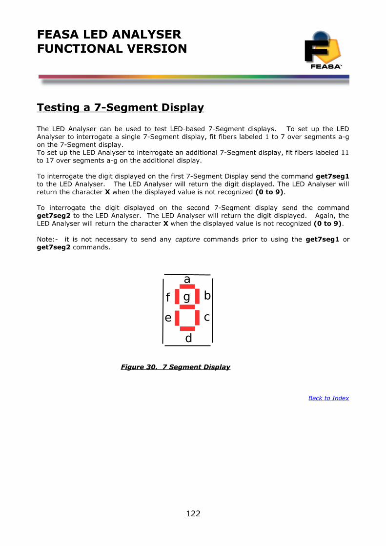
FEASA LED ANALYSERFUNCTIONAL VERSION
Testing a 7-Segment Display
The LED Analyser can be used to test LED-based 7-Segment displays. To set up the LEDAnalyser to interrogate a single 7-Segment display, fit fibers labeled 1 to 7 over segments a-gon the 7-Segment display.To set up the LED Analyser to interrogate an additional 7-Segment display, fit fibers labeled 11to 17 over segments a-g on the additional display.
To interrogate the digit displayed on the first 7-Segment Display send the command get7seg1to the LED Analyser. The LED Analyser will return the digit displayed. The LED Analyser willreturn the character X when the displayed value is not recognized (0 to 9).
To interrogate the digit displayed on the second 7-Segment display send the commandget7seg2 to the LED Analyser. The LED Analyser will return the digit displayed. Again, theLED Analyser will return the character X when the displayed value is not recognized (0 to 9).
Note:- it is not necessary to send any capture commands prior to using the get7seg1 orget7seg2 commands.
Figure 30. 7 Segment Display
Back to Index
122
b
c
d
e
f g
a
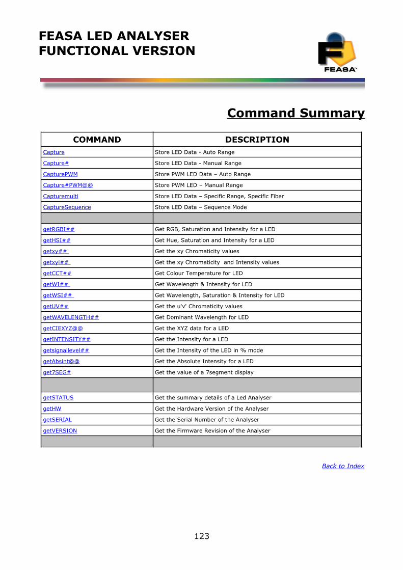
FEASA LED ANALYSERFUNCTIONAL VERSION
Command Summary
COMMAND DESCRIPTIONCapture Store LED Data - Auto Range
Capture# Store LED Data - Manual Range
CapturePWM Store PWM LED Data – Auto Range
Capture#PWM@@ Store PWM LED – Manual Range
Capturemulti Store LED Data – Specific Range, Specific Fiber
CaptureSequence Store LED Data – Sequence Mode
getRGBI## Get RGB, Saturation and Intensity for a LED
getHSI## Get Hue, Saturation and Intensity for a LED
getxy## Get the xy Chromaticity values
getxy i ## Get the xy Chromaticity and Intensity values
getCCT## Get Colour Temperature for LED
getWI## Get Wavelength & Intensity for LED
getW S I## Get Wavelength, Saturation & Intensity for LED
getUV## Get the u'v' Chromaticity values
getWAVELENGTH## Get Dominant Wavelength for LED
get CIEXYZ@@ Get the XYZ data for a LED
getINTENSITY## Get the Intensity for a LED
getsignallevel## Get the Intensity of the LED in % mode
getAbsint@@ Get the Absolute Intensity for a LED
get7SEG# Get the value of a 7segment display
getSTATUS Get the summary details of a Led Analyser
getHW Get the Hardware Version of the Analyser
getSERIAL Get the Serial Number of the Analyser
getVERSION Get the Firmware Revision of the Analyser
Back to Index
123
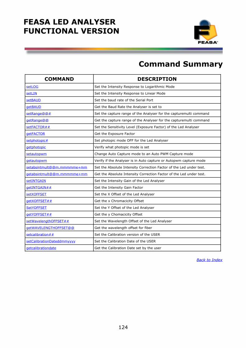
FEASA LED ANALYSERFUNCTIONAL VERSION
Command Summary
COMMAND DESCRIPTIONs etLOG Set the Intensity Response to Logarithmic Mode
set LIN Set the Intensity Response to Linear Mode
setBAUD Set the baud rate of the Serial Port
getBAUD Get the Baud Rate the Analyser is set to
set R ange@@# Set the capture range of the Analyser for the capturemulti command
getRange@@ Get the capture range of the Analyser for the capturemulti command
setFACTOR## Set the Sensitivity Level (Exposure Factor) of the Led Analyser
getFACTOR Get the Exposure Factor
set photopic # Set photopic mode OFF for the Led Analyser
getphotopic Verify what photopic mode is set
setautopwm Change Auto Capture mode to an Auto PWM Capture mode
getautopwm Verify if the Analyser is in Auto capture or Autopwm capture mode
setabsintmult@@m.mmmmme+mm Set the Absolute Intensity Correction Factor of the Led under test.
getabsintmult@@m.mmmmme+mm Get the Absolute Intensity Correction Factor of the Led under test.
s etINTGAIN Set the Intensity Gain of the Led Analyser
getINTGAIN## Get the Intensity Gain Factor
s etXOFFSET Set the X Offset of the Led Analyser
getXOFFSET## Get the x Chromacicity Offset
SetYOFFSET Set the Y Offset of the Led Analyser
getYOFFSET## Get the y Chomacicity Offset
s etWavelengthOFFSET## Set the Wavelength Offset of the Led Analyser
getWAVELENGTHOFFSET@@ Get the wavelength offset for fiber
setcalibration # # Set the Calibration version of the USER
s etCalibrationDateddmmyyyy Set the Calibration Date of the USER
getcalibrationdate Get the Calibration Date set by the user
Back to Index
124
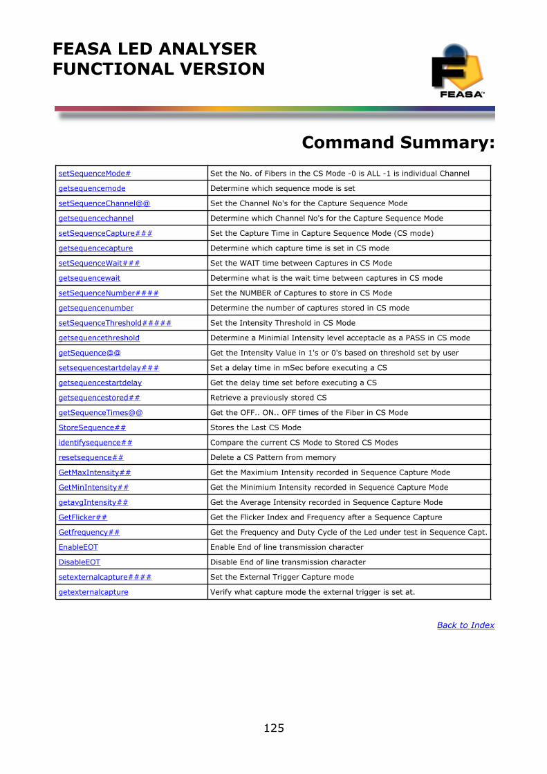
FEASA LED ANALYSERFUNCTIONAL VERSION
Command Summary:
s etSequenceMode# Set the No. of Fibers in the CS Mode -0 is ALL -1 is individual Channel
getsequencemode Determine which sequence mode is set
se tSequenceChannel @@ Set the Channel No's for the Capture Sequence Mode
getsequencechannel Determine which Channel No's for the Capture Sequence Mode
s etSequenceCapture### Set the Capture Time in Capture Sequence Mode (CS mode)
getsequencecapture Determine which capture time is set in CS mode
s etSequenceWait### Set the WAIT time between Captures in CS Mode
getsequencewait Determine what is the wait time between captures in CS mode
s etSequenceNumber### # Set the NUMBER of Captures to store in CS Mode
getsequencenumber Determine the number of captures stored in CS mode
s etSequenceThreshold##### Set the Intensity Threshold in CS Mode
getsequencethreshold Determine a Minimial Intensity level acceptacle as a PASS in CS mode
getSequence @ @ Get the Intensity Value in 1's or 0's based on threshold set by user
setsequencestartdelay### Set a delay time in mSec before executing a CS
getsequencestartdelay Get the delay time set before executing a CS
getsequencestored## Retrieve a previously stored CS
getSequenceTimes @@ Get the OFF.. ON.. OFF times of the Fiber in CS Mode
StoreSequence## Stores the Last CS Mode
identifysequence ## Compare the current CS Mode to Stored CS Modes
resetsequence ## Delete a CS Pattern from memory
GetMaxIntensity## Get the Maximium Intensity recorded in Sequence Capture Mode
GetMin Intensity## Get the Minimium Intensity recorded in Sequence Capture Mode
getavgIntensity## Get the Average Intensity recorded in Sequence Capture Mode
GetFlicker## Get the Flicker Index and Frequency after a Sequence Capture
Getfrequency## Get the Frequency and Duty Cycle of the Led under test in Sequence Capt.
EnableEOT Enable End of line transmission character
DisableEOT Disable End of line transmission character
setexternalcapture#### Set the External Trigger Capture mode
getexternalcapture Verify what capture mode the external trigger is set at.
Back to Index
125
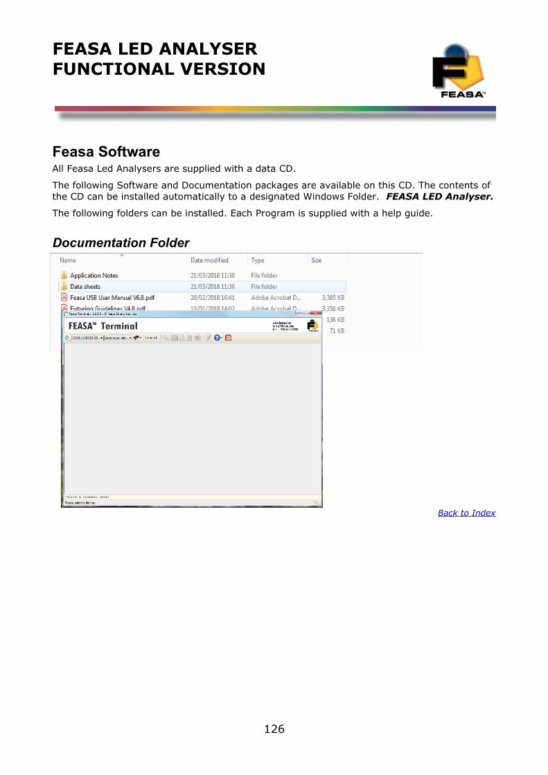
FEASA LED ANALYSERFUNCTIONAL VERSION
Feasa SoftwareAll Feasa Led Analysers are supplied with a data CD.
The following Software and Documentation packages are available on this CD. The contents of the CD can be installed automatically to a designated Windows Folder. FEASA LED Analyser.
The following folders can be installed. Each Program is supplied with a help guide.
Documentation Folder
Feasa Terminal
Back to Index
126
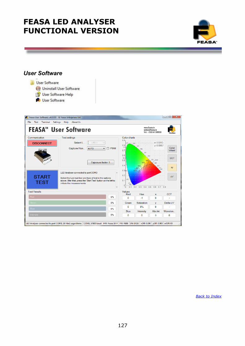
FEASA LED ANALYSERFUNCTIONAL VERSION
User Software
Back to Index
127
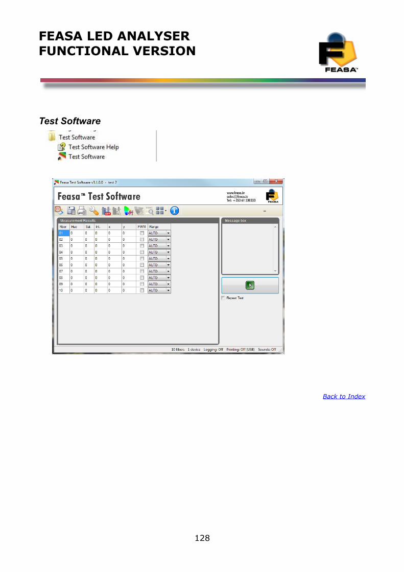
FEASA LED ANALYSERFUNCTIONAL VERSION
Test Software
Back to Index
128
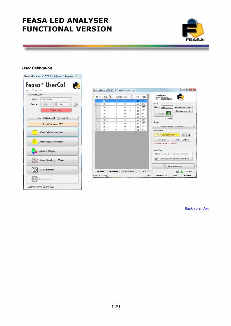
FEASA LED ANALYSERFUNCTIONAL VERSION
User Calibration
Back to Index
129

FEASA LED ANALYSERFUNCTIONAL VERSION
Programming
Back to Index
130
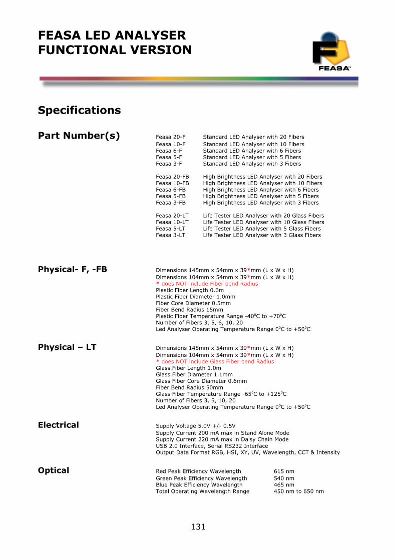
FEASA LED ANALYSERFUNCTIONAL VERSION
Specifications
Part Number(s) Feasa 20-F Standard LED Analyser with 20 FibersFeasa 10-F Standard LED Analyser with 10 FibersFeasa 6-F Standard LED Analyser with 6 FibersFeasa 5-F Standard LED Analyser with 5 FibersFeasa 3-F Standard LED Analyser with 3 Fibers
Feasa 20-FB High Brightness LED Analyser with 20 FibersFeasa 10-FB High Brightness LED Analyser with 10 FibersFeasa 6-FB High Brightness LED Analyser with 6 FibersFeasa 5-FB High Brightness LED Analyser with 5 FibersFeasa 3-FB High Brightness LED Analyser with 3 Fibers
Feasa 20-LT Life Tester LED Analyser with 20 Glass FibersFeasa 10-LT Life Tester LED Analyser with 10 Glass FibersFeasa 5-LT Life Tester LED Analyser with 5 Glass FibersFeasa 3-LT Life Tester LED Analyser with 3 Glass Fibers
Physical- F, -FB Dimensions 145mm x 54mm x 39*mm (L x W x H)Dimensions 104mm x 54mm x 39*mm (L x W x H)* does NOT include Fiber bend RadiusPlastic Fiber Length 0.6mPlastic Fiber Diameter 1.0mmFiber Core Diameter 0.5mmFiber Bend Radius 15mmPlastic Fiber Temperature Range -400C to +700CNumber of Fibers 3, 5, 6, 10, 20Led Analyser Operating Temperature Range 00C to +500C
Physical – LT Dimensions 145mm x 54mm x 39*mm (L x W x H)Dimensions 104mm x 54mm x 39*mm (L x W x H)* does NOT include Glass Fiber bend RadiusGlass Fiber Length 1.0mGlass Fiber Diameter 1.1mmGlass Fiber Core Diameter 0.6mmFiber Bend Radius 50mmGlass Fiber Temperature Range -650C to +1250CNumber of Fibers 3, 5, 10, 20Led Analyser Operating Temperature Range 00C to +500C
Electrical Supply Voltage 5.0V +/- 0.5VSupply Current 200 mA max in Stand Alone ModeSupply Current 220 mA max in Daisy Chain ModeUSB 2.0 Interface, Serial RS232 InterfaceOutput Data Format RGB, HSI, XY, UV, Wavelength, CCT & Intensity
Optical Red Peak Efficiency Wavelength 615 nmGreen Peak Efficiency Wavelength 540 nmBlue Peak Efficiency Wavelength 465 nmTotal Operating Wavelength Range 450 nm to 650 nm
131
FEASA LED ANALYSERFUNCTIONAL VERSION
Accuracy White X=± 0.01, Y = ± 0.01 @ x=0.33, y=0.33 using OH-3 Optical Head
Red (630nm) ± 4nm Green (520nm) ± 2nm Blue (450nm) ± 5nm Yellow (590nm) ± 2nm
These accuracy's are based on the Led Analyser being calibrated at a point in time against known set values.
Capture Test Times Auto Range 350msRange 1 ( Low Intensity) 650msRange 2 ( Medium Intensity) 200msRange 3 ( High Intensity) 22msRange 4 ( Super Intensity) 4msRange 5 ( Ultra Intensity) 2ms
Back to Index
132

FEASA LED ANALYSERFUNCTIONAL VERSION
Warranty
1. Feasa Enterprises Limited (herein referred to as Feasa) warrants Feasa hardware, accessories and supplies against defects in materials and workmanship for the period ofone year. If Feasa receives notice of such defects during the warranty period, Feasa will, at its option, either repair or replace products which prove to be defective. Replacement products may be either new or like-new.
2. Feasa warrants that Feasa software will not fail to execute its programming instructions, for the period of one year, due to defects in material or workmanship whenproperly installed and used. If Feasa receives notice of defects during the warranty period, Feasa will replace software media which does not execute its programming instructions due to such defects.
3. Feasa does not warrant that the operation of Feasa products will be uninterrupted or error free. If Feasa is unable, within a reasonable time, to repair or replace any productto a condition as warranted, customer will be entitled to a refund of the purchase price upon prompt return of the product to Feasa.
4. Feasa products may contain re-manufactured parts equivalent to new in performance ormay have been subject to incidental use
5. The warranty period begins on the date of deliver
6. Warranty does not apply to defects resulting from:(a) improper or inadequate maintenance or calibration,(b) software, interfacing, parts or supplies not supplied by Feasa, (c) unauthorized modification or misuse,(d) operation outside the published environmental specifications for the product, or (e) improper site preparation or maintenance.
7. TO THE EXTENT ALLOWED BY LOCAL LAW, THE ABOVE WARRANTIES ARE EXCLUSIVE AND NO OTHER WARRANTY OR CONDITION, WHETHER WRITTEN OR ORAL, IS EXPRESSED OR IMPLIED AND FEASA SPECIFICALLY DISCLAIMS ANY IMPLIED WARRANTIES OR CONDITIONS OF MERCHANTABILITY, SATISFACTORY QUALITY, AND FITNESS FOR A PARTICULAR PURPOSE.
8. TO THE EXTENT ALLOWED BY LOCAL LAW, THE REMEDIES IN THIS WARRANTY STATEMENT ARE CUSTOMER S SOLE AND EXCLUSIVE REMEDIES. EXCEPT AS ʼINDICATED ABOVE, IN NO EVENT WILL FEASA OR ITS SUPPLIERS BE LIABLE FOR LOSSOF DATA OR FOR DIRECT, SPECIAL, INCIDENTAL, CONSEQUENTIAL (INCLUDING LOST PROFIT OR DATA), OR OTHER DAMAGE WHETHER BASED IN CONTRACT, TORT, OR OTHERWISE.
Back to Index
133