Embed Size (px)
Citation preview

FEA Summary Report_1
For APA Shipping Frame
Ang Lee
July 28, 2020
7/28/2020 Ang Lee FEA Summary for APA Shipping frame 1

7/28/2020 Ang Lee FEA Summary for APA Shipping frame
APA Shipping Frame mainly Consists of :- S355 steel Tubing with S (yield)=355 MPa ; Su=470 MPa.- Carbon steel plate. - Shock Absorber _Wire Rope Isolator (WRI)
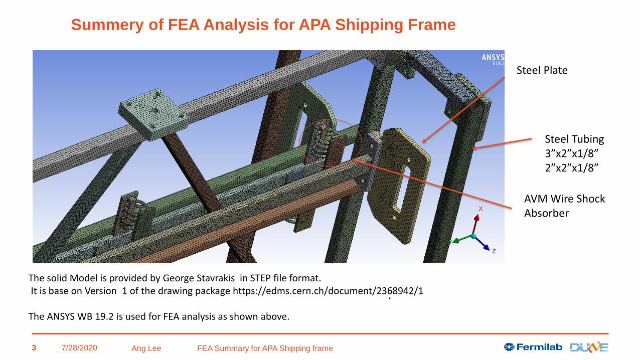
Summary of FEA Analysis for APA Shipping Frame
2
7/28/2020 Ang Lee FEA Summary for APA Shipping frame
The solid Model is provided by George Stavrakis in STEP file format.It is base on Version 1 of the drawing package https://edms.cern.ch/document/2368942/1
The ANSYS WB 19.2 is used for FEA analysis as shown above.
AVM Wire Shock Absorber
Steel Plate
Steel Tubing3”x2”x1/8”2”x2”x1/8”
Summery of FEA Analysis for APA Shipping Frame
.
3

FEA Model: Loading and boundary condition
7/28/2020 Ang Lee FEA Summary for APA Shipping frame
• STP file was imported into ANSYS WB 19.2. It is based on Version 1 of the drawing package https://edms.cern.ch/document/2368942/1. This EDMS folder includes the model, the technical drawings, and the center of mass calculations.
• The model is meshed with the solid element containing the middle node. The mesh size is ~10 mm which results a model of ~3.26 million nodes or ~10 million degree of freedom.
• The connection is treated as “bonded” with an exception of the “pin” connection area which is modeled as “slip joint”. The gigantic model requires some iterations to solve.
• The integrated APA mass is 562 kg (5.5 KN) for the upper one and 516 kg (5.1 KN) for the lower one respectively (EDMS #2281422). The FEA model uses 7497 (N) for the upper one and 7656 (N) for the lower one, as shown at right. It is modeled as the remote force scoped to the attachment plate where the APA is attached. It is a very conservative approach as it is analyzed without considering the stiffness of APA detector frame itself.
• The density of the steel frame has been modified to include the weight of frame itself and other components ( for example, the protection panel and etc). The total weight of the structure is 31,840 (N), 3249 kg including both APAs and the shipping frame. This number has a ~25% or more contingency for further design iterations. It is an upper limit for the load.
4

Applicable Code used for FEA Analysis
• ASME BTH-1 Codes is used for the lifting device. It agrees with the Compliance
Office preliminary requirements_ Memorandum dated 2/11/2020 EDMS No.:2093094 for service
class A.
7/28/2020 Ang Lee FEA Summary for APA Shipping frame 5
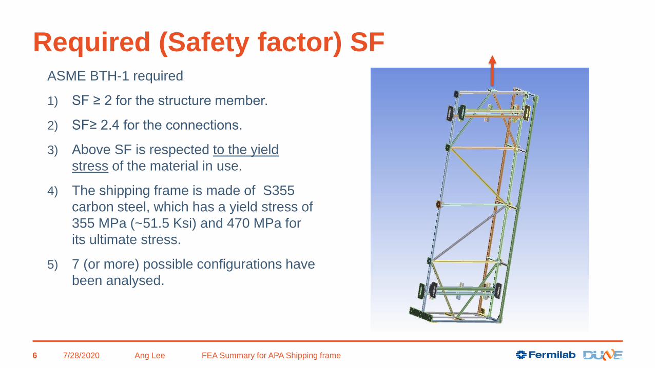
Required (Safety factor) SF
7/28/2020 Ang Lee FEA Summary for APA Shipping frame
ASME BTH-1 required
1) SF ≥ 2 for the structure member.
2) SF≥ 2.4 for the connections.
3) Above SF is respected to the yield
stress of the material in use.
4) The shipping frame is made of S355
carbon steel, which has a yield stress of
355 MPa (~51.5 Ksi) and 470 MPa for
its ultimate stress.
5) 7 (or more) possible configurations have
been analysed.
6

Load case study
7/28/2020 Ang Lee FEA Summary for APA Shipping frame
• The load case 3,4 and 5
(total 7 configurations )
are considered as the
critical case to drive the
design.
• We will go case by case
in following pages
Transport frame Load Case FEA Configuration Status
1 _ Sitting on the factory floor See case 3 Done
2 _ Lifting at the factory See case 3 Done
3 _ Lifting in front of the Ross Shaft Case 3a ,3b and 3c Done
4 _ Lifting down the Ross Shaft Case 4 (1 G and 2 G) Done
5 _Lifting at the bottom of Ross shaft Case 5a,5b,and 5c Done
6_ On the underground trolley The floor requirement from CF
shows very smooth.
Done
7_ Lifting the frame vertical on a trolley Similar to case 4 ( Trolley
weight is ~750 kg, it is still
within 25% contingency).
Done
8_ Transport frame sitting in the vertical
position
No worse than case 4 Done
9_ Additional case study for the
attachment plate
Done Done
10_ Additional case study for the
attachment plate
Done Done
7
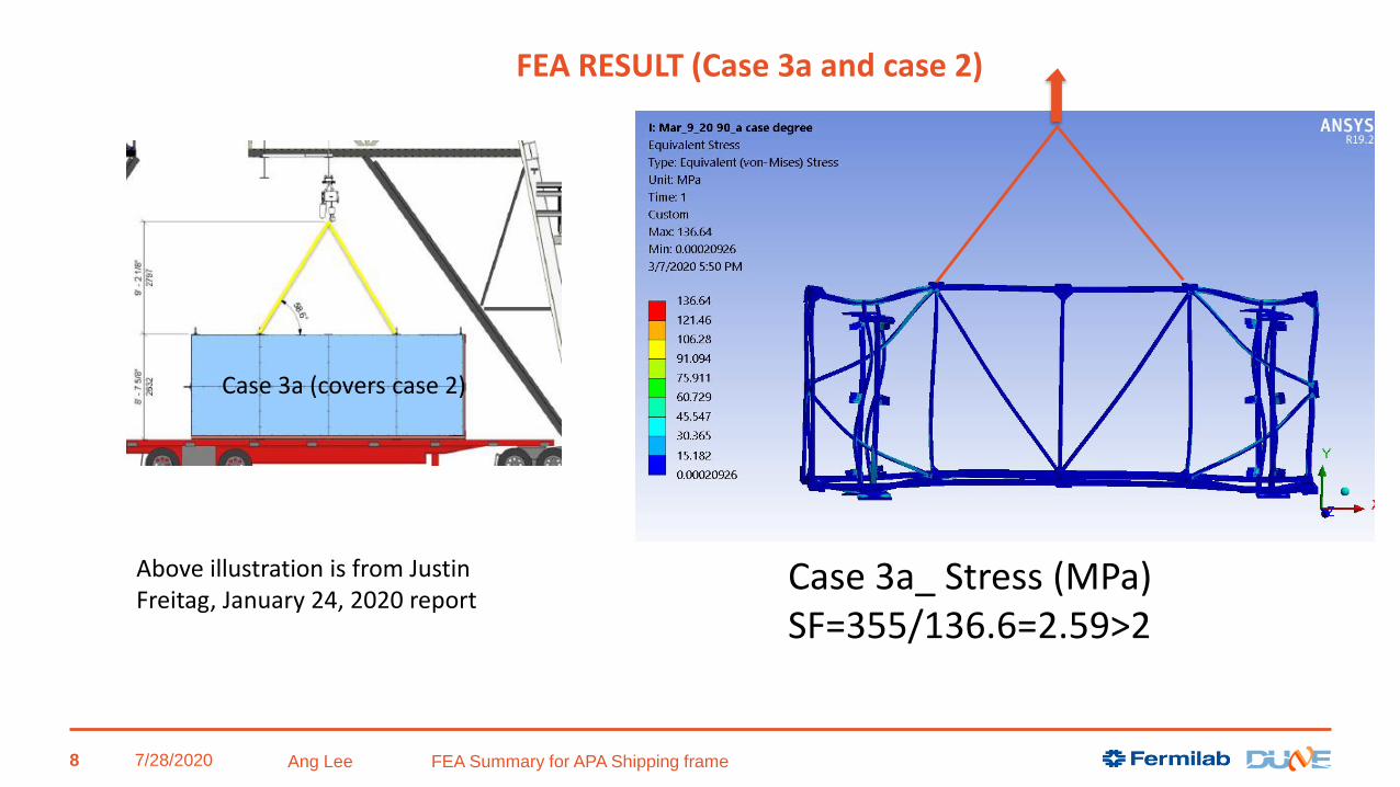
Case 3a_ Stress (MPa)SF=355/136.6=2.59>2
Above illustration is from Justin Freitag, January 24, 2020 report
7/28/2020 Ang Lee FEA Summary for APA Shipping frame
FEA RESULT (Case 3a and case 2)
Case 3a (covers case 2)
8

FEA RESULT (Case 3a and case 2)
7/28/2020 Ang Lee FEA Summary for APA Shipping frame
The stress around the lifting point is around 70 MPa
without considering stress concentration.
9

FEA RESULT (Case 3a and case 2)
7/28/2020 Ang Lee FEA Summary for APA Shipping frame 10

FEA RESULT (Case 3a )_ Buckling result SF min=69.
It is done without considering the stiffness contribution from the APA tubing
7/28/2020 Ang Lee FEA Summary for APA Shipping frame
SF=69.3 (first buckling mode)
SF=78.4 (2nd buckling mode)
11

7/28/2020 Ang Lee FEA Summary for APA Shipping frame
Case 3b
From Case 3a to Case 3b (just before the rotation start)
12
Case 3b
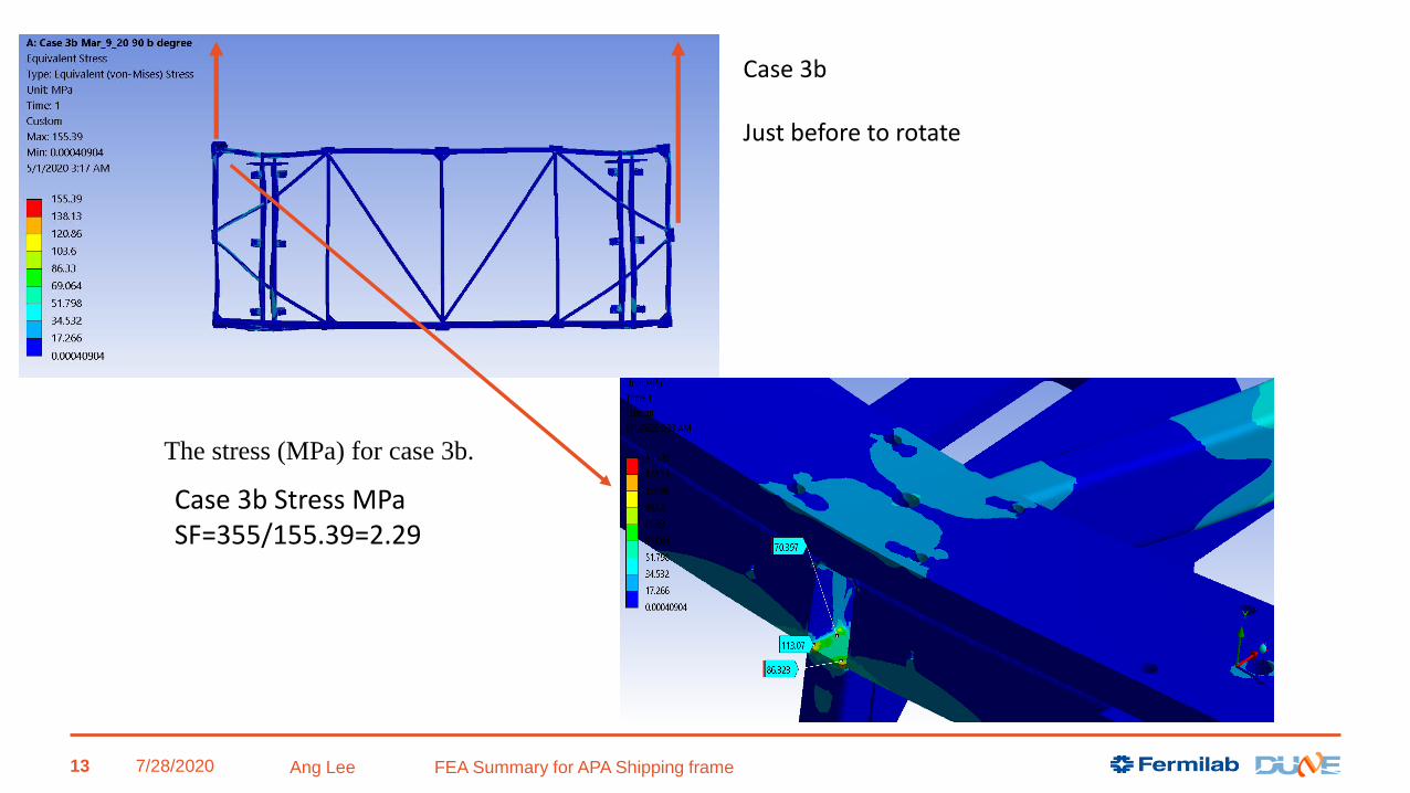
Case 3b Stress MPaSF=355/155.39=2.29
7/28/2020 Ang Lee FEA Summary for APA Shipping frame
Case 3b
Just before to rotate
The stress (MPa) for case 3b.
13

7/28/2020 Ang Lee FEA Summary for APA Shipping frame
The buckling SF (min)=23 for case 3b
SF=23 (first buckling mode)
SF=38.9 ( 2nd buckling mode)
14

7/28/2020
Two corner points
One point
Case 3c Stress (MPa)SF=355/118.63=2.99
Ang Lee FEA Summary for APA Shipping frame
Case 3c
15

7/28/2020 Ang Lee FEA Summary for APA Shipping frame
The buckling SF (min)=20.5 for case 3c
SF=20.5 (first buckling mode)
SF=33.99 ( 2nd buckling mode)
16

Case 4 Vertical stress (MPa); SF=355/108.90=3.26Finished 1st rotation (from Horizontal to Vertical)
F=31840 N=3249 Kg
7/28/2020 Ang Lee FEA Summary for APA Shipping frame 17
Case 4 Vertical position
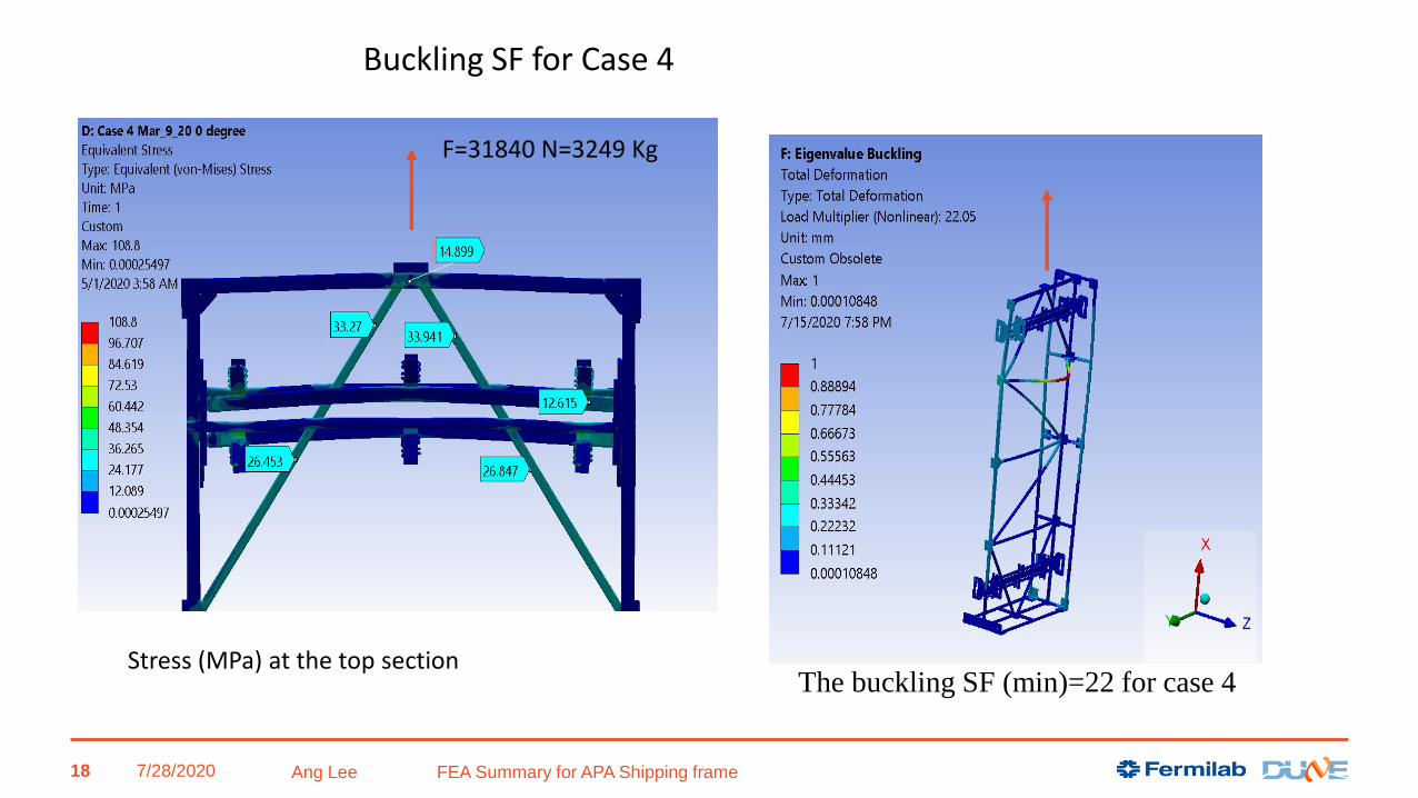
7/28/2020 Ang Lee FEA Summary for APA Shipping frame
The buckling SF (min)=22 for case 4
F=31840 N=3249 Kg
Stress (MPa) at the top section
18
Buckling SF for Case 4

Case 5a The Second rotation (45 degree) Stress MPa; SF=355/122.01=2.91 (Second rotation)
7/28/2020 Ang Lee FEA Summary for APA Shipping frame 19
Case 5a _ Second rotation

The buckling SF (min)=51.68 for case 5a
7/28/2020 Ang Lee FEA Summary for APA Shipping frame 20

Case 5b Stress (MPa); SF (min) = 355/161.32 = 2.20.(Just before the yellow sling to picked up the frame )
7/28/2020 Ang Lee FEA Summary for APA Shipping frame
Case 5b
21

7/28/2020 Ang Lee FEA Summary for APA Shipping frame
The buckling SF (min)=46.7 for case 5b
22

Case 5c Stress (MPa); SF=355/145.01=2.45
7/28/2020 Ang Lee FEA Summary for APA Shipping frame
case 5c
23

7/28/2020 Ang Lee FEA Summary for APA Shipping frame
The buckling SF (min)=20.1 for case 5c
24

7/28/2020 Ang Lee FEA Summary for APA Shipping frame
Case7 Configurations(Critical conditions)
Pick up points
Peak
Stress (MPa)
SF (min)
For the frame
BTH-1 req satisfaction
SF Buckling
3a = 2 Landscape Mode 2 136.92 2.59 Y 69.3
3b Landscape Mode 3 155.39 2.28 Y 23
3c 45 degree _1st rotation 3 118.63 2.99 Y 20.5
4 Vertical position 3 108.80 3.26 Y 22.05
5a 45 degree _2nd rotation 3 122.01 2.90 Y 51.6
5bLandscape Mode
upside down3 161.32 2.20 Y 46.5
5cLandscape Mode
upside down2 145.01 2.45 Y 20.1
Table 2 - Summary of the results of the lift case analysis
25

Case study conclusions• Analysis of all 7 lifting configurations at SURF is summarized in Table 2.
• The shipping frame structure is more than adequate to satisfy the ASME BTH-1
requirement of SF (min) ≥ 2 based on the yield strength.
• For the case of the accident (2G load), the stress of the frame structure will remain
below the yield stress of 355 MPa by (resultant stress x 2 < 355 MPa).
• SF of the buckling is more than adequate to resist the frame instability.
• The analysis is done without considering the stiffness of the APA frame (stainless steel
tubing 4”x4”x1/8”). The actual stress will be lower than analyzed. The buckling SF will
be much higher than calculated above as well.
• Weld stress needs to be checked. It is difficult task. So many welds and so many
cases. The connection force and moment are extracted from FEA model. The weld
stress is calculated according BTH code requirement for Nd=2.4 minimum.
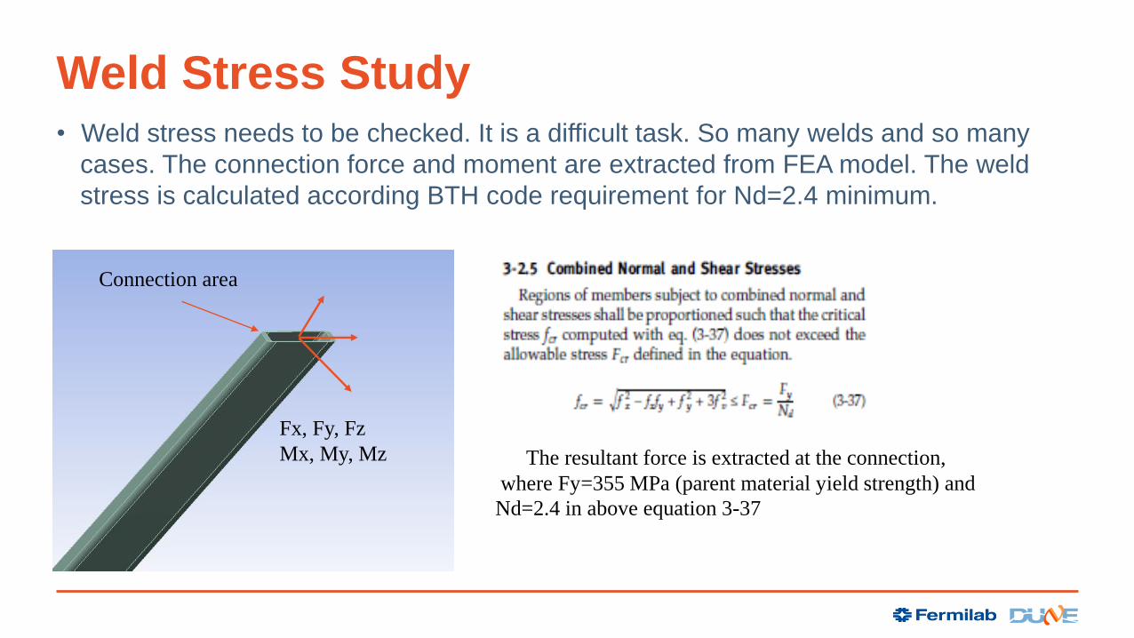
Weld Stress Study• Weld stress needs to be checked. It is a difficult task. So many welds and so many
cases. The connection force and moment are extracted from FEA model. The weld
stress is calculated according BTH code requirement for Nd=2.4 minimum.
Connection area
Fx, Fy, Fz
Mx, My, Mz The resultant force is extracted at the connection,
where Fy=355 MPa (parent material yield strength) and
Nd=2.4 in above equation 3-37

Weld stress study
7/28/2020 Ang Lee FEA Summary for APA Shipping frame
• Extracting the force (Fx, Fy and Fz) and moment (Mx, My and Mz) at each connection as illustrated. Both normal and shear stress are calculated based on the given weld size (3.2 mm).
• The combined stress is obtained based on BTH-1 code Eq (3-37). A complete detailed list for all 7 load cases is included in Appendix. All weld connections exceed the code requirement of SF(Nd)>2.4.
• It is noteworthy to mention that the connection between the 30 mm/50 mm plates and 3.2 mm wall thickness tubing requires a transition weld to satisfy BTH-1 section of 3-3.4.3 and table 3-3.4.3-1 requirement. A cheek plate design has been proposed. This solution is being validated by a BTH-qualified vender. However, the current analysis uses a minimum weld thickness of 3.2 mm. There is no further calculation is needed at this moment.
Connection area
28
Fx, Fy, FzMx. My, Mz

7/28/2020 Ang Lee FEA Summary for APA Shipping frame
Examples of some critical weld along the load path
29

Weld SIZE width effective width DY1 DX1 DY2 DX2 AREA IXX IYY IZZ Rmax Combine force
3.20 2.26 80.00 31.80 86.40 38.20 756.48 696362.60 186966.49 883329.09 47.23
absorber Plate Fx Fy Fz Mx My Mz (MPa) Sz_n Sy+Sx_s Smx_n Smy_n Smz_s Sn_sub S_shear Scombined SF
1.00 2363.3 -379.7 -185.86 32017.92 116499.44 -65662.68 0.25 3.16 1.99 11.90 3.51 14.13 6.68 18.26 19.44
2.00 926.31 33.85 -53.06 5093.2 50904.84 3775.08 0.07 1.23 0.32 5.20 0.20 5.59 1.43 6.11 58.11
3.00 2289.4 358.1 -215.87 4220.2 111375.47 57553.54 0.29 3.06 0.26 11.38 3.08 11.92 6.14 15.98 22.22
4.00 2625.45 176.52 181.42 32212.32 -124464.63 -47357.54 0.24 3.48 2.00 -12.71 2.53 -10.48 6.01 14.77 24.04
5.00 800.39 -24.82 -10.99 4432.57 -47243.13 3009.6 0.01 1.06 0.27 -4.83 0.16 -4.54 1.22 5.00 70.94
6.00 2535.7 -138.05 292.53 -340.93 -110788.37 34864.15 0.39 3.36 -0.02 -11.32 1.86 -10.95 5.22 14.20 24.99
7.00 1961.97 361.99 -184.12 29635.45 -99984.01 -58186.26 0.24 2.64 1.84 -10.21 3.11 -8.13 5.75 12.86 27.61
8.00 488.84 -14.72 132.05 2246.25 -11272.66 2067.59 0.17 0.65 0.14 -1.15 0.11 -0.84 0.76 1.56 228.15
9.00 1970.63 -358.78 -225.14 205.66 -98502.28 55613.52 0.30 2.65 0.01 -10.06 2.97 -9.75 5.62 13.78 25.76
10.00 2123.27 -158.9 190.08 26514.74 101074.73 -40796.33 0.25 2.81 1.64 10.33 2.18 12.22 5.00 14.98 23.71
11.00 446.06 8.71 401.75 2177.47 14178.69 1934.41 0.53 0.59 0.14 1.45 0.10 2.11 0.69 2.43 145.99
12.00 2123.39 130.72 289.21 -1373.42 94353.87 33392.83 0.38 2.81 -0.09 9.64 1.79 9.94 4.60 12.73 27.88
SF (min) 19.44
Absorber has 12 weld connections
Weld stress at the vertical position
7/28/2020 Ang Lee FEA Summary for APA Shipping frame
BTH equation (3-37)
> 2.4 (per ASME BTH -1 requirement)
30
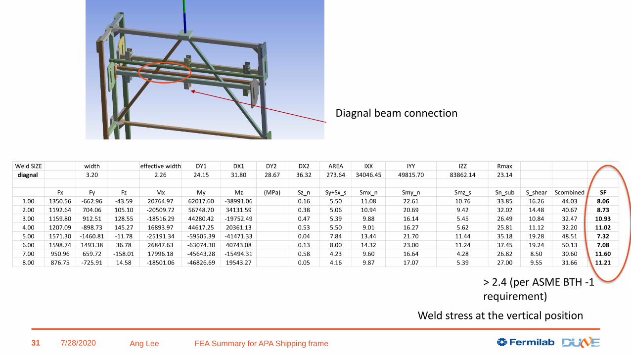
Diagnal beam connection
Weld SIZE width effective width DY1 DX1 DY2 DX2 AREA IXX IYY IZZ Rmax
diagnal 3.20 2.26 24.15 31.80 28.67 36.32 273.64 34046.45 49815.70 83862.14 23.14
Fx Fy Fz Mx My Mz (MPa) Sz_n Sy+Sx_s Smx_n Smy_n Smz_s Sn_sub S_shear Scombined SF
1.00 1350.56 -662.96 -43.59 20764.97 62017.60 -38991.06 0.16 5.50 11.08 22.61 10.76 33.85 16.26 44.03 8.06
2.00 1192.64 704.06 105.10 -20509.72 56748.70 34131.59 0.38 5.06 10.94 20.69 9.42 32.02 14.48 40.67 8.73
3.00 1159.80 912.51 128.55 -18516.29 44280.42 -19752.49 0.47 5.39 9.88 16.14 5.45 26.49 10.84 32.47 10.93
4.00 1207.09 -898.73 145.27 16893.97 44617.25 20361.13 0.53 5.50 9.01 16.27 5.62 25.81 11.12 32.20 11.02
5.00 1571.30 -1460.81 -11.78 -25191.34 -59505.39 -41471.33 0.04 7.84 13.44 21.70 11.44 35.18 19.28 48.51 7.32
6.00 1598.74 1493.38 36.78 26847.63 -63074.30 40743.08 0.13 8.00 14.32 23.00 11.24 37.45 19.24 50.13 7.08
7.00 950.96 659.72 -158.01 17996.18 -45643.28 -15494.31 0.58 4.23 9.60 16.64 4.28 26.82 8.50 30.60 11.60
8.00 876.75 -725.91 14.58 -18501.06 -46826.69 19543.27 0.05 4.16 9.87 17.07 5.39 27.00 9.55 31.66 11.21
Weld stress at the vertical position
7/28/2020 Ang Lee FEA Summary for APA Shipping frame
> 2.4 (per ASME BTH -1 requirement)
31

top section
_diagnal beam
Weld SIZE widtheffective
widthDY1 DZ1 DY2 DZ2 AREA IZZ IYY IXX Rmax
diagnal tubing 3.2 2.2624 62.285 50.8 66.8098 55.3248 532.1608 351962.7618 262352.1121 614314.8739 43.3716
Fx Fy Fz Mx My Mz (MPa) Sx_n Sy+Sz_s Smz_n Smy_n Smx_s Sn_sub S_shear Scombined SF
1 -15153.3 10912.82 25.82 -1701.53 7836.49 2968.18 28.48 20.51 0.28 0.83 0.12 29.58 20.63 46.38 7.65
2 -15613.7 -11258.2 27.94 -4008.88 10840.6 -105.62 29.34 21.16 0.01 1.14 0.28 30.49 21.44 48.05 7.39
3 491.17 369.36 32.75 1676.09 -2153.1 6663.57 0.92 0.70 0.63 0.23 0.12 1.78 0.82 2.27 156.12
4 -18.82 31.96 23.11 -3299.53 -1140.07 10112.17 0.04 0.07 0.96 0.12 0.23 1.12 0.31 1.24 287.30
SF (min) 7.39
Connection at the top
Weld stress at the vertical position
7/28/2020 Ang Lee FEA Summary for APA Shipping frame
SF>>2.4 required by ASME BTH-1
50 mm plate
Weld SIZE widtheffective
widthDZ1 DY1 DZ2 DY2 AREA IYY IZZ IXX Rmax
3.20 2.26 38.10 190.00 42.62 194.52 1052.58 379712.42 4368722.19 4748434.61 99.57
Fx Fy Fz Mx My Mz (MPa) Sx_n Sz+Sy_s Smy_n Smz_n Smx_s Sn_sub S_shear Scombined SF
1 30525.26 377.41 1.78 -532.44 42921.23 30335.6 29.00 0.36 2.41 0.68 0.01 32.08 0.37 32.09 11.06
32

Sample of Weld stress at the vertical position
7/28/2020 Ang Lee FEA Summary for APA Shipping frame
Weld SIZE width effective width DY1 DX1 DY2 DX2 AREA IXX IYY IZZ Rmax Combine force
3.20 2.26 80.00 31.80 86.40 38.20 756.48 696362.60 186966.49 883329.09 47.23
absorber Plate Fx Fy Fz Mx My Mz (MPa) Sz_n Sy+Sx_s Smx_n Smy_n Smz_s Sn_sub S_shear Scombined SF
1.00 2363.3 -379.7 -185.86 32017.92 116499.44 -65662.68 0.25 3.16 1.99 11.90 3.51 14.13 6.68 18.26 19.44
2.00 926.31 33.85 -53.06 5093.2 50904.84 3775.08 0.07 1.23 0.32 5.20 0.20 5.59 1.43 6.11 58.11
3.00 2289.4 358.1 -215.87 4220.2 111375.47 57553.54 0.29 3.06 0.26 11.38 3.08 11.92 6.14 15.98 22.22
4.00 2625.45 176.52 181.42 32212.32 -124464.63 -47357.54 0.24 3.48 2.00 -12.71 2.53 -10.48 6.01 14.77 24.04
5.00 800.39 -24.82 -10.99 4432.57 -47243.13 3009.6 0.01 1.06 0.27 -4.83 0.16 -4.54 1.22 5.00 70.94
6.00 2535.7 -138.05 292.53 -340.93 -110788.37 34864.15 0.39 3.36 -0.02 -11.32 1.86 -10.95 5.22 14.20 24.99
7.00 1961.97 361.99 -184.12 29635.45 -99984.01 -58186.26 0.24 2.64 1.84 -10.21 3.11 -8.13 5.75 12.86 27.61
8.00 488.84 -14.72 132.05 2246.25 -11272.66 2067.59 0.17 0.65 0.14 -1.15 0.11 -0.84 0.76 1.56 228.15
9.00 1970.63 -358.78 -225.14 205.66 -98502.28 55613.52 0.30 2.65 0.01 -10.06 2.97 -9.75 5.62 13.78 25.76
10.00 2123.27 -158.9 190.08 26514.74 101074.73 -40796.33 0.25 2.81 1.64 10.33 2.18 12.22 5.00 14.98 23.71
11.00 446.06 8.71 401.75 2177.47 14178.69 1934.41 0.53 0.59 0.14 1.45 0.10 2.11 0.69 2.43 145.99
12.00 2123.39 130.72 289.21 -1373.42 94353.87 33392.83 0.38 2.81 -0.09 9.64 1.79 9.94 4.60 12.73 27.88
SF (min) 19.44
Weld SIZE width effective width DY1 DX1 DY2 DX2 AREA IXX IYY IZZ Rmax
Diagnal Tubing 3.20 2.26 24.15 31.80 28.67 36.32 273.64 34046.45 49815.70 83862.14 23.14
flat side
Fx Fy Fz Mx My Mz (MPa) Sz_n Sy+Sx_s Smx_n Smy_n Smz_s Sn_sub S_shear Scombined SF
1.00 1350.22 -665.32 -40.62 20708.16 62089.23 -38773.28 0.15 5.50 11.05 22.64 10.70 33.83 16.20 43.95 8.08
2.00 1195.1 706.84 108.53 -20453.77 56802.11 34125.15 0.40 5.07 10.91 20.71 9.42 32.02 14.49 40.68 8.73
3.00 1159.74 912.94 128.18 -18533.28 44299.89 -19785.73 0.47 5.39 9.89 16.15 5.46 26.51 10.85 32.50 10.92
4.00 1207.61 -898.26 145.75 16886.7 44616.86 20295.79 0.53 5.50 9.01 16.27 5.60 25.81 11.10 32.18 11.03
5.00 1574.11 -1460.55 -9.96 -24973.2 -59508.11 -41485.62 0.04 7.85 13.32 21.70 11.45 35.05 19.29 48.43 7.33
6.00 1599.21 1491.25 33.42 26423.57 -62948.08 40604.18 0.12 7.99 14.10 22.95 11.20 37.17 19.19 49.87 7.12
7.00 951.75 659.16 -157.94 18029.57 -45707.28 -15561.73 0.58 4.23 9.62 16.66 4.29 26.86 8.52 30.65 11.58
8.00 877.69 -726.92 14.52 -18492.11 -46798.31 19499.19 0.05 4.16 9.86 17.06 5.38 26.98 9.55 31.64 11.22
SF (min) 7.12
top section
_diagnal beam
Weld SIZE width effective width DY1 DZ1 DY2 DZ2 AREA IZZ IYY IXX Rmax
diagnal tubing 3.2 2.2624 62.285 50.8 66.8098 55.3248 532.1608 351962.7618 262352.1121 614314.8739 43.3716
Fx Fy Fz Mx My Mz (MPa) Sx_n Sy+Sz_s Smz_n Smy_n Smx_s Sn_sub S_shear Scombined SF
1 -15153.3 10912.82 25.82 -1701.53 7836.49 2968.18 28.48 20.51 0.28 0.83 0.12 29.58 20.63 46.38 7.65
2 -15613.7 -11258.2 27.94 -4008.88 10840.6 -105.62 29.34 21.16 0.01 1.14 0.28 30.49 21.44 48.05 7.39
3 491.17 369.36 32.75 1676.09 -2153.1 6663.57 0.92 0.70 0.63 0.23 0.12 1.78 0.82 2.27 156.12
4 -18.82 31.96 23.11 -3299.53 -1140.07 10112.17 0.04 0.07 0.96 0.12 0.23 1.12 0.31 1.24 287.30
SF (min) 7.39
Weld SIZE width effective width DY1 DX1 DY2 DX2 AREA IXX IYY IZZ Rmax
Vertical flat 3.20 2.26 63.50 31.80 68.02 36.32 451.69 274321.53 101537.40 375858.92 38.56
Fx Fy Fz Mx My Mz (MPa) Sz_n Sy+Sx_s Smx_n Smy_n Smz_s Sn_sub S_shear Scombined SF
1.00 1531.21 194.91 -1568.69 7070.63 -43235.56 77394.38 3.47 3.42 0.88 7.73 7.94 12.08 11.36 23.09 15.38
2.00 1483.07 -323.52 239.51 9876.92 -65405.63 -78127.85 0.53 3.36 1.22 11.70 8.01 13.45 11.38 23.86 14.88
3.00 1294.09 160.35 -1394.85 19752.47 -29523.35 116350.86 3.09 2.89 2.45 5.28 11.94 10.82 14.82 27.86 12.74
4.00 1366.94 -396.73 -184.03 -10809.84 -52830.91 -122879.48 0.41 3.15 1.34 9.45 12.61 11.20 15.76 29.50 12.03
5.00 1533.59 -516.97 -1817.24 21981.38 41457.7 90118.91 4.02 3.58 2.73 7.42 9.24 14.16 12.83 26.35 13.47
6.00 1543.95 727.55 -203.79 -11476.22 69020.87 -90857.67 0.45 3.78 1.42 12.35 9.32 14.22 13.10 26.78 13.26
7.00 1187.96 -162.81 -1216.57 7173.56 30991.36 95513.1 2.69 2.65 0.89 5.54 9.80 9.13 12.45 23.42 15.16
8.00 1224.31 421.5 212.41 9318.62 47892.8 -99411.15 0.47 2.87 1.16 8.57 10.20 10.19 13.06 24.82 14.30
SF (min) 12.03
33
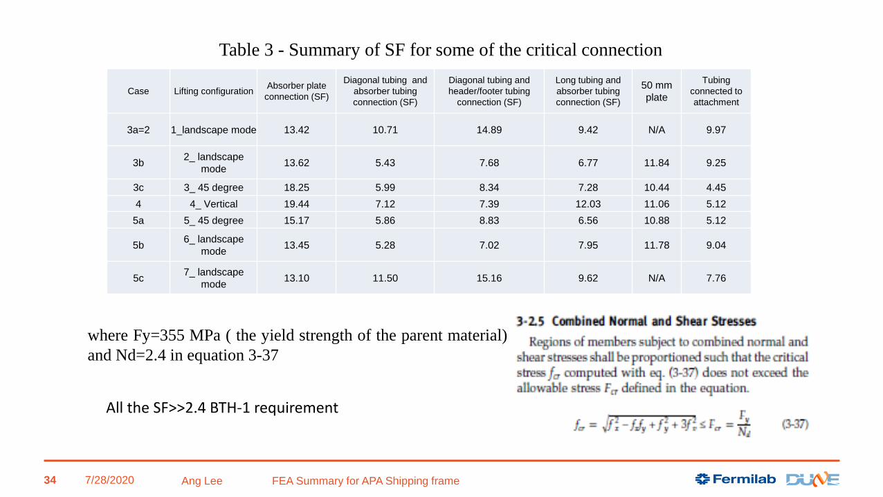
The full list is attached in Appendix B
7/28/2020 Ang Lee FEA Summary for APA Shipping frame
Table 3 - Summary of SF for some of the critical connection
where Fy=355 MPa ( the yield strength of the parent material)
and Nd=2.4 in equation 3-37
34
Case Lifting configurationAbsorber plate
connection (SF)
Diagonal tubing and
absorber tubing
connection (SF)
Diagonal tubing and
header/footer tubing
connection (SF)
Long tubing and
absorber tubing
connection (SF)
50 mm
plate
Tubing
connected to
attachment
3a=2 1_landscape mode 13.42 10.71 14.89 9.42 N/A 9.97
3b2_ landscape
mode13.62 5.43 7.68 6.77 11.84 9.25
3c 3_ 45 degree 18.25 5.99 8.34 7.28 10.44 4.45
4 4_ Vertical 19.44 7.12 7.39 12.03 11.06 5.12
5a 5_ 45 degree 15.17 5.86 8.83 6.56 10.88 5.12
5b6_ landscape
mode13.45 5.28 7.02 7.95 11.78 9.04
5c7_ landscape
mode13.10 11.50 15.16 9.62 N/A 7.76
All the SF>>2.4 BTH-1 requirement

Additional case study
Case 9 and 10
7/28/2020 Ang Lee FEA Summary for APA Shipping frame 35

Attachment Plate and Connection Study (case 9 & case 10)
• In the previous case study, the APA detector weight was treated as force remotely
applied to the attachment plate from its gravity center. it is a conservative approach
without considering the stiffness of APA frame.
• However, it does not address how the actual APA detector is connected to the
transport frame in great detail, which requires a separate FEA model.
• The APA frame is connected to shipping frame using 8 stainless steel M16 to M20
adaptors attached to a steel plate. During the installation, the APA detectors will be
loaded into the shipping frame from the top.
• Total weight of the APA will be sitting on the lower attachment plate. Instead of 8
stainless steel adaptors, only 4 of them will participate in the load bearing, as it is
considered as the worst case. To understand the resulting stress, a separate FEA
model is created as case 9/10.

GRAVITY LOAD IS HOLD BY THESE TWO PLATE_ LOWER SECTION
1 G load =7659 N
6 absorber plates:Each of them is connected by THREEE springs with Kx, Ky and Kz , provided by Jake and Dan (PSL). THANK YOU!The spring stiffness is as follows:
X = 726 kN/mY = 726 kN/mZ = 2.742 MN/m
7/28/2020 Ang Lee FEA Summary for APA Shipping frame
Top bracket is a “SLIP JOINT_SLIDING
37
M16 bolt SS 304
M16 to M20 adaptor SS 304
79.6x50.8x12.7 mm SS 304 plate welded to APA tubing

7/28/2020 Ang Lee FEA Summary for APA Shipping frame
The deflection of APA frame is about 4.5-2.5=~2 mm The vertical tubing has moved downward 1.66~1.9 mm (more like translation due to the spring attachment).It is consistent with X=7659 N/(726e3*6)=~1.75 mm (Good agreement !)
38

The FEA model indicates the stress is below ~125 Mpa << 355 MPa; SF=355/125=2.84
7/28/2020 Ang Lee FEA Summary for APA Shipping frame 39

7/28/2020 Ang Lee FEA Summary for APA Shipping frame
Check the weld stress
W
e
l
d
S
I
Z
E
widtheffective
widthDX1 DZ1 DX2 DZ2 AREA IZZ IXX IYY Rmax
3.20 2.26 62.29 38.10 66.81 42.62 474.70 292083.22 144104.52 436187.74 39.62
Fx Fy Fz Mx My Mz (MPa) SY_n Sx+Sz_s Smz_n Smy_S Smx_N Sn_sub S_shearScombin
edSF
1
.
0
0
-2.53 -4130.60 -77.65 532030.00 -1347.90 53473.00 8.70 0.16 6.12 0.12 78.68 93.50 0.29 93.50 3.80
2
.
0
0
-10.71 -3554.30 -68.19 468380.00 6140.90 -99012.00 7.49 0.15 11.32 0.56 69.27 88.08 0.70 88.09 4.03
40
Weld stress check

7/28/2020 Ang Lee FEA Summary for APA Shipping frame
SS 304 Syield=205 MPa minSu=515 MPa min
M16X2 SS bolt (grade 304); SF=205/73=2.82
SS 304Adaptor (MPa) SF=205/72=2.85
41

7/28/2020 Ang Lee FEA Summary for APA Shipping frame 42
M20 steel bolt –stress (MPa)
M20 steel bolt is class 8.8With minimum yield of 660 MPa and 830 MPa ultimate strength.
SF=660/57.268=11.5
This bolt connection has been changed to the bolt/nut (instead of tap hole)

7/28/2020 Ang Lee FEA Summary for APA Shipping frame
S355 carbon steelSyield=355 MPa min
Attachment plate S355; SF=355/88.68=4
43

7/28/2020 Ang Lee FEA Summary for APA Shipping frame 44
D p Ds At Dp Le min (mm)
L (design) (mm)
M16X2 16.00 2.00 14.12 156.67 14.70 13.57 24.00
M20X2.5 20.00 2.50 17.65 244.79 18.38 16.96 20.00
Thread Engagement Check
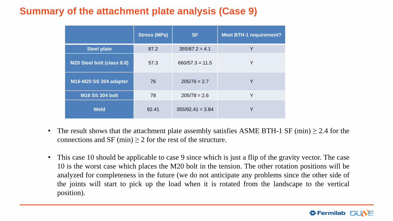
Summary of the attachment plate analysis (Case 9)
Stress (MPa) SF Meet BTH-1 requirement?
Steel plate 87.2 355/87.2 = 4.1 Y
M20 Steel bolt (class 8.8) 57.3 660/57.3 = 11.5 Y
M16-M20 SS 304 adapter 76 205/76 = 2.7 Y
M16 SS 304 bolt 78 205/78 = 2.6 Y
Weld 92.41 355/92.41 = 3.84 Y
• The result shows that the attachment plate assembly satisfies ASME BTH-1 SF (min) ≥ 2.4 for the
connections and SF (min) ≥ 2 for the rest of the structure.
• This case 10 should be applicable to case 9 since which is just a flip of the gravity vector. The case
10 is the worst case which places the M20 bolt in the tension. The other rotation positions will be
analyzed for completeness in the future (we do not anticipate any problems since the other side of
the joints will start to pick up the load when it is rotated from the landscape to the vertical
position).

Conclusions
• Based on the preliminary static structural analysis result, the current design of the
shipping frame is adequate to satisfy the requirements of ASME BTH-1 2017.
• The dynamic analysis will be continued to understand the dynamic response during
the shipping environment with a proper shock absorber. We will present the result
tomorrow.
• As the design progressed, the FEA analysis will be updated accordingly.
• Lastly, in a design improvement the two APAs within the shipping frame will be
translated by 15 mm along their long direction to improve clearances (on the bottom
ends) with no net change in the center of gravity. This is called Version 2 of the
technical drawing package. Compared with the ~6,700 mm overall dimension, this
shift has a negligible impact on these results. However, the analysis will be updated to
reflect this and all updates to the final shipping frame design.

Reference
1) “Design of Below-the Hook Lifting Devices”, ASME BTH-1-2017, March 15, 2017.
2) “Compliance Office Preliminary Requirements Memorandum”, dated 2/11/2020 EDMS
No.:2093094.
3) “Design recommendations for APA transport frame and detector” by M. Zimbru, J-L.
Grenard, O. Beltramello (CERN).