Embed Size (px)
Citation preview
APA Shipping frame Design
Mariana Zimbru, DUNE Compliance Office
LBNF/DUNE FDR: APA
August 31 – September 2, 2021
Outline
M. Zimbru | APA Shipping Frame Design2
• Purpose
• Requirements
• Geometrical configuration
• Materials
• Loading situations
• Structural analysis
• Codes and regulations
• FEA results and verifications
• Final considerations
September 2, 2021
Documentation
M. Zimbru | APA Shipping Frame Design3
• APA shipping frame memorandum: https://edms.cern.ch/document/2330505/2
• APA Shipping frame drawings: https://edms.cern.ch/document/2477326/1
• APA shipping frame analysis plan: https://edms.cern.ch/document/2509414/2
• Transportation analysis guidelines: https://edms.cern.ch/document/2366873/1
• APA shipping frame engineering analysis: https://edms.cern.ch/document/2607623/1
• AVMR shipping frame assembly analysis (Vibrostop): https://edms.cern.ch/document/2617816/1
September 2, 2021
Purpose
4
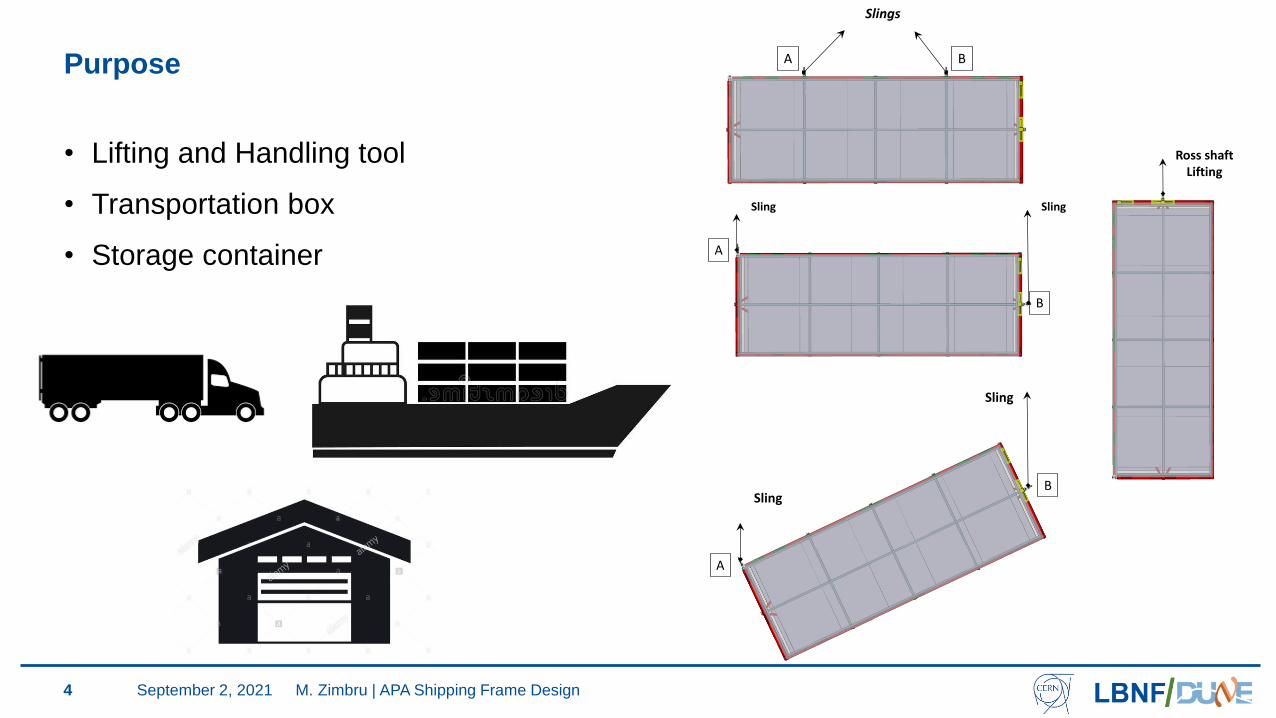
• Lifting and Handling tool
• Transportation box
• Storage container
A B
Slings
A
B
SlingSling
A
B
Sling
Sling
Ross shaft Lifting
M. Zimbru | APA Shipping Frame DesignSeptember 2, 2021
Geometrical configuration
5
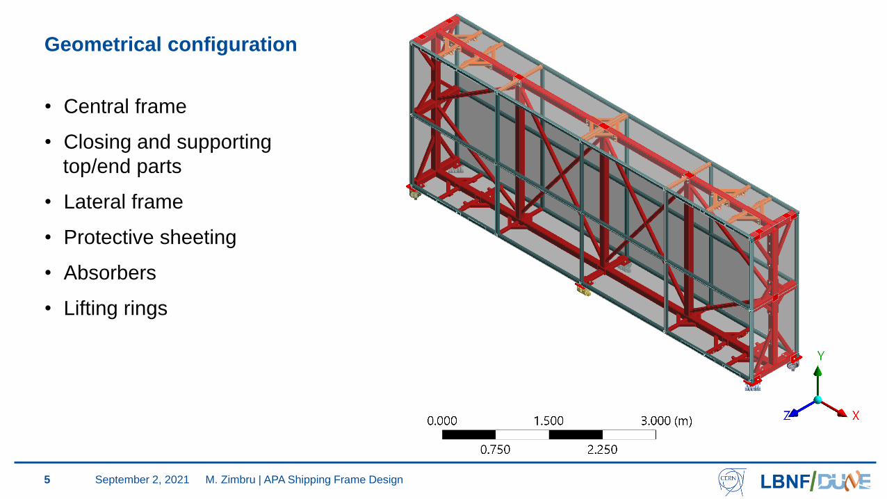
• Central frame
• Closing and supporting
top/end parts
• Lateral frame
• Protective sheeting
• Absorbers
• Lifting rings
M. Zimbru | APA Shipping Frame DesignSeptember 2, 2021
Geometrical configuration
6
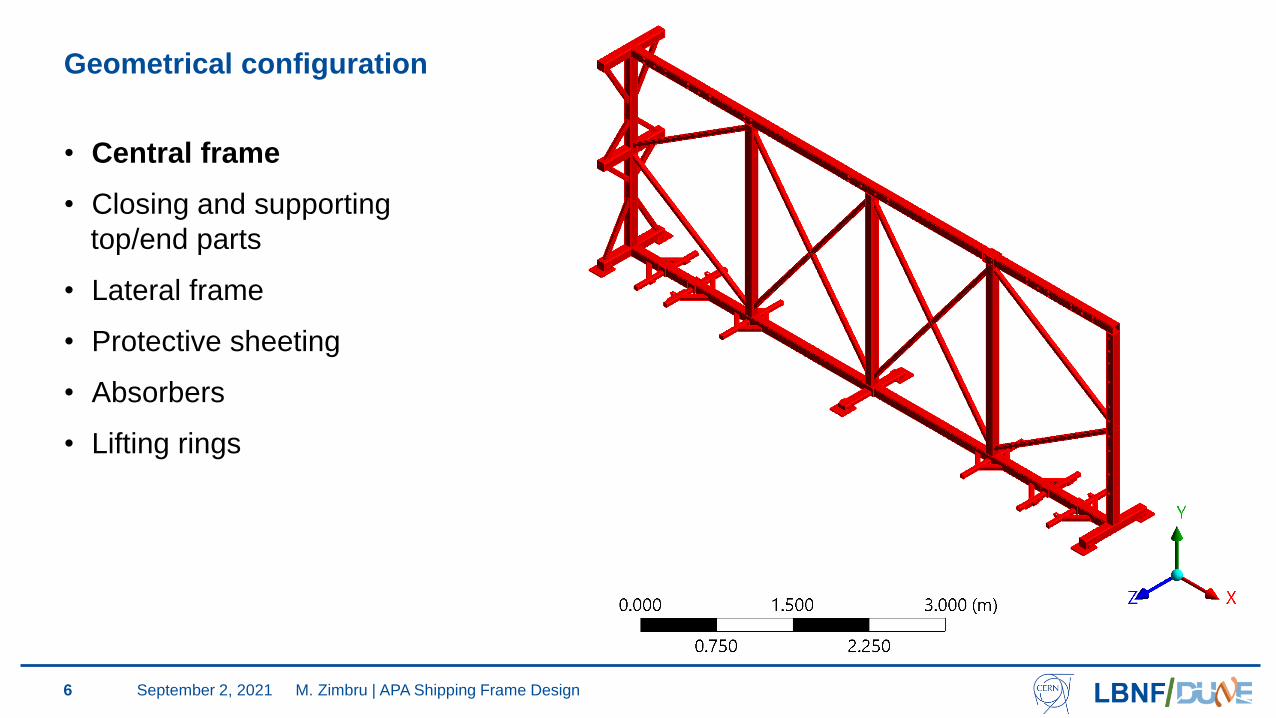
• Central frame
• Closing and supporting
top/end parts
• Lateral frame
• Protective sheeting
• Absorbers
• Lifting rings
M. Zimbru | APA Shipping Frame DesignSeptember 2, 2021
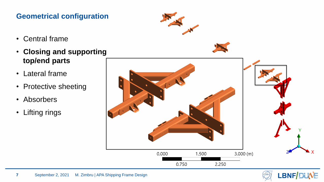
Geometrical configuration
7
• Central frame
• Closing and supporting
top/end parts
• Lateral frame
• Protective sheeting
• Absorbers
• Lifting rings
M. Zimbru | APA Shipping Frame DesignSeptember 2, 2021
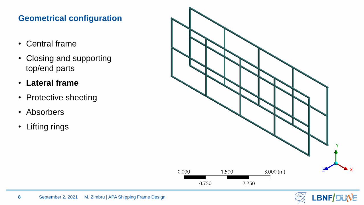
Geometrical configuration
8
• Central frame
• Closing and supporting
top/end parts
• Lateral frame
• Protective sheeting
• Absorbers
• Lifting rings
M. Zimbru | APA Shipping Frame DesignSeptember 2, 2021
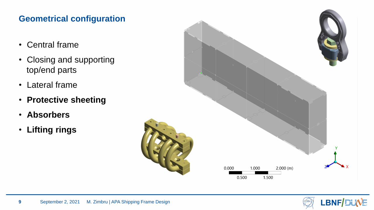
Geometrical configuration
9
• Central frame
• Closing and supporting
top/end parts
• Lateral frame
• Protective sheeting
• Absorbers
• Lifting rings
M. Zimbru | APA Shipping Frame DesignSeptember 2, 2021
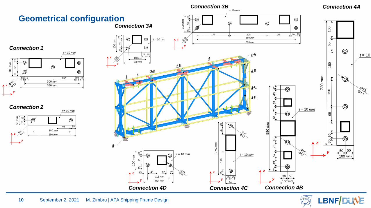
Geometrical configuration
10
300 mm
350 mm
25 25 20 25
100 m
m
25
25
50
t = 10 mm
130
y
z
t = 10 mm
180 mm
250 mm
65 35
50 m
m
25
25
y
z
t = 10 mm
100 mm
150 mm
25 25
100 m
m
25
25
50
y
z
t = 10 mm
550 mm
600 mm
30 25
100 m
m
25
25
50
145200175
y
z
t = 10 mm
100 mm
50 50
72
0 m
m
30
65
15
03
01
50
10
09
5
y
z
t = 10 mm
100 mm
50 50
580 m
m
25
43
57
75
40
25
43
57
75
40
y
z
t = 10 mm
25 25
275 m
m
25
20
11
04
0
50y
z
t = 10 mm
115 mm
150 mm
12 20
100 m
m
25
25
50
4520
y
z
Connection 1
Connection 2
Connection 3A
Connection 3B Connection 4A
Connection 4C Connection 4BConnection 4D
M. Zimbru | APA Shipping Frame DesignSeptember 2, 2021
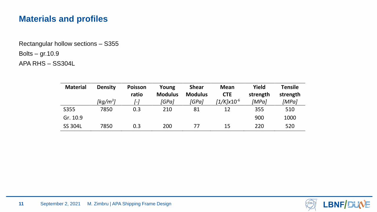
Materials and profiles
11
Material Density Poisson ratio
Young Modulus
Shear Modulus
Mean CTE
Yield strength
Tensile strength
[kg/m3] [-] [GPa] [GPa] [1/K]x10-6 [MPa] [MPa]
S355 7850 0.3 210 81 12 355 510
Gr. 10.9
SS 304L
7850
0.3
200
77
15
900
220
1000
520
Rectangular hollow sections – S355
Bolts – gr.10.9
APA RHS – SS304L
M. Zimbru | APA Shipping Frame DesignSeptember 2, 2021
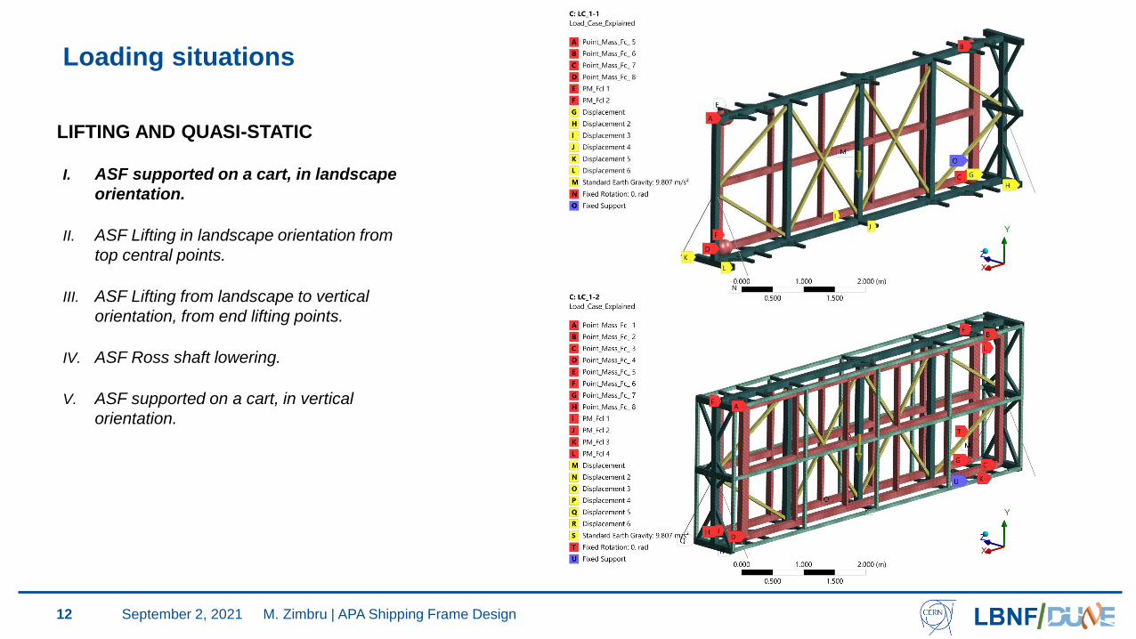
Loading situations
12
LIFTING AND QUASI-STATIC
I. ASF supported on a cart, in landscape
orientation.
II. ASF Lifting in landscape orientation from
top central points.
III. ASF Lifting from landscape to vertical
orientation, from end lifting points.
IV. ASF Ross shaft lowering.
V. ASF supported on a cart, in vertical
orientation.
M. Zimbru | APA Shipping Frame DesignSeptember 2, 2021
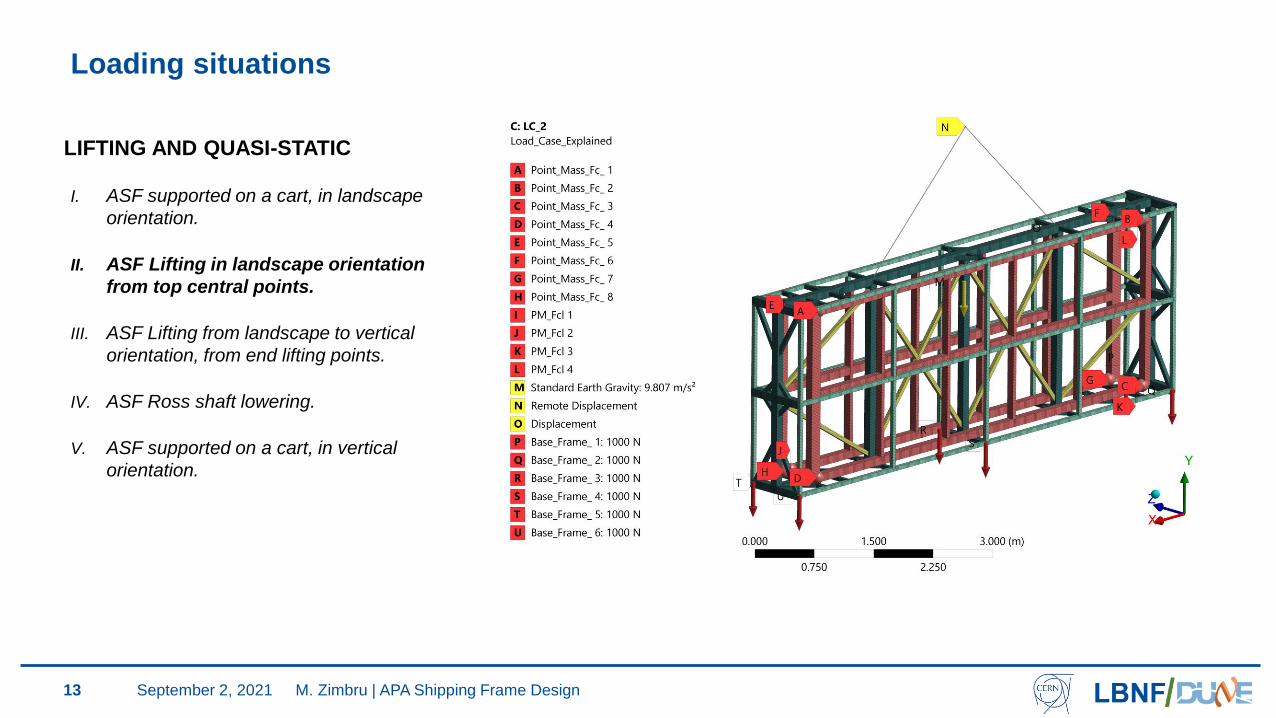
Loading situations
13
LIFTING AND QUASI-STATIC
I. ASF supported on a cart, in landscape
orientation.
II. ASF Lifting in landscape orientation
from top central points.
III. ASF Lifting from landscape to vertical
orientation, from end lifting points.
IV. ASF Ross shaft lowering.
V. ASF supported on a cart, in vertical
orientation.
M. Zimbru | APA Shipping Frame DesignSeptember 2, 2021
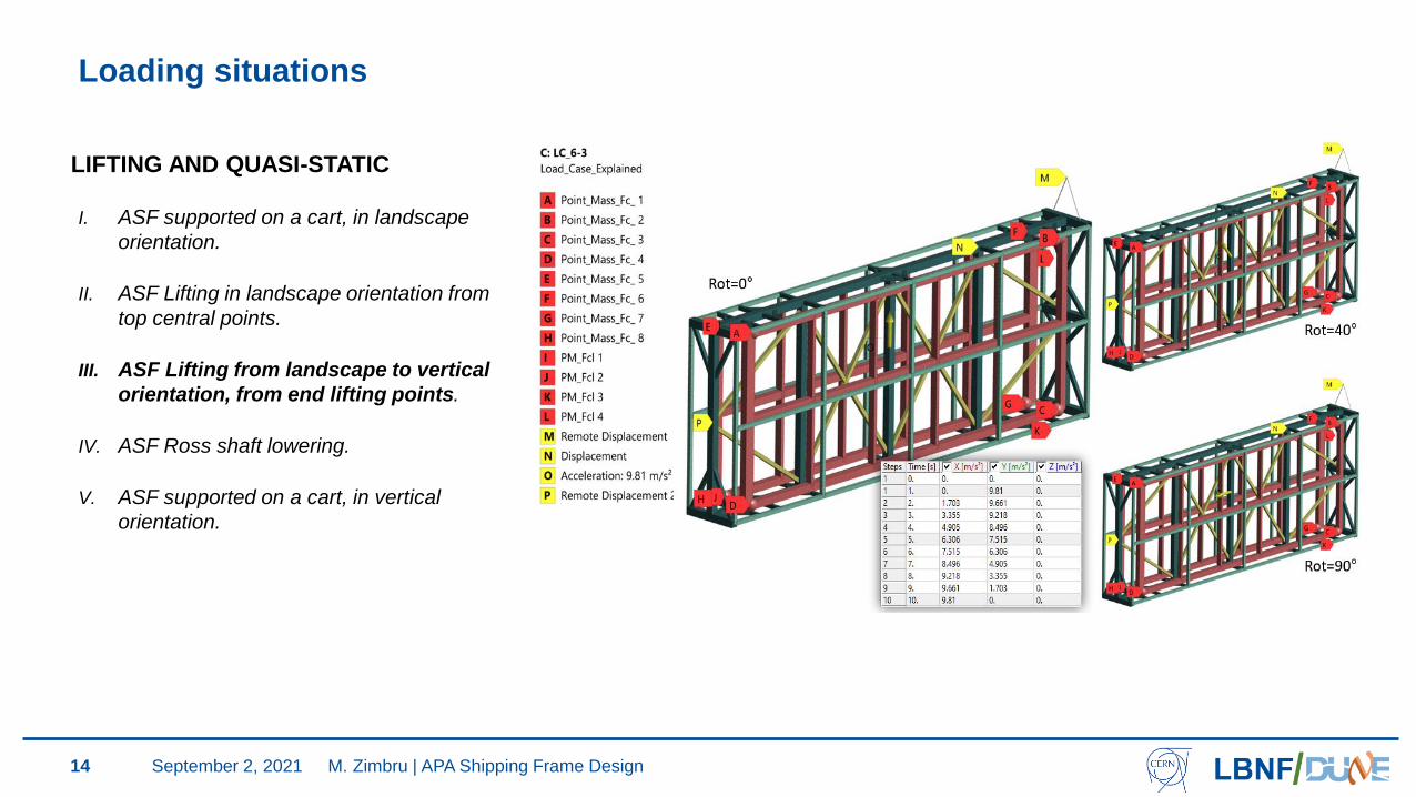
Loading situations
14
LIFTING AND QUASI-STATIC
I. ASF supported on a cart, in landscape
orientation.
II. ASF Lifting in landscape orientation from
top central points.
III. ASF Lifting from landscape to vertical
orientation, from end lifting points.
IV. ASF Ross shaft lowering.
V. ASF supported on a cart, in vertical
orientation.
M. Zimbru | APA Shipping Frame DesignSeptember 2, 2021
Loading situations
15
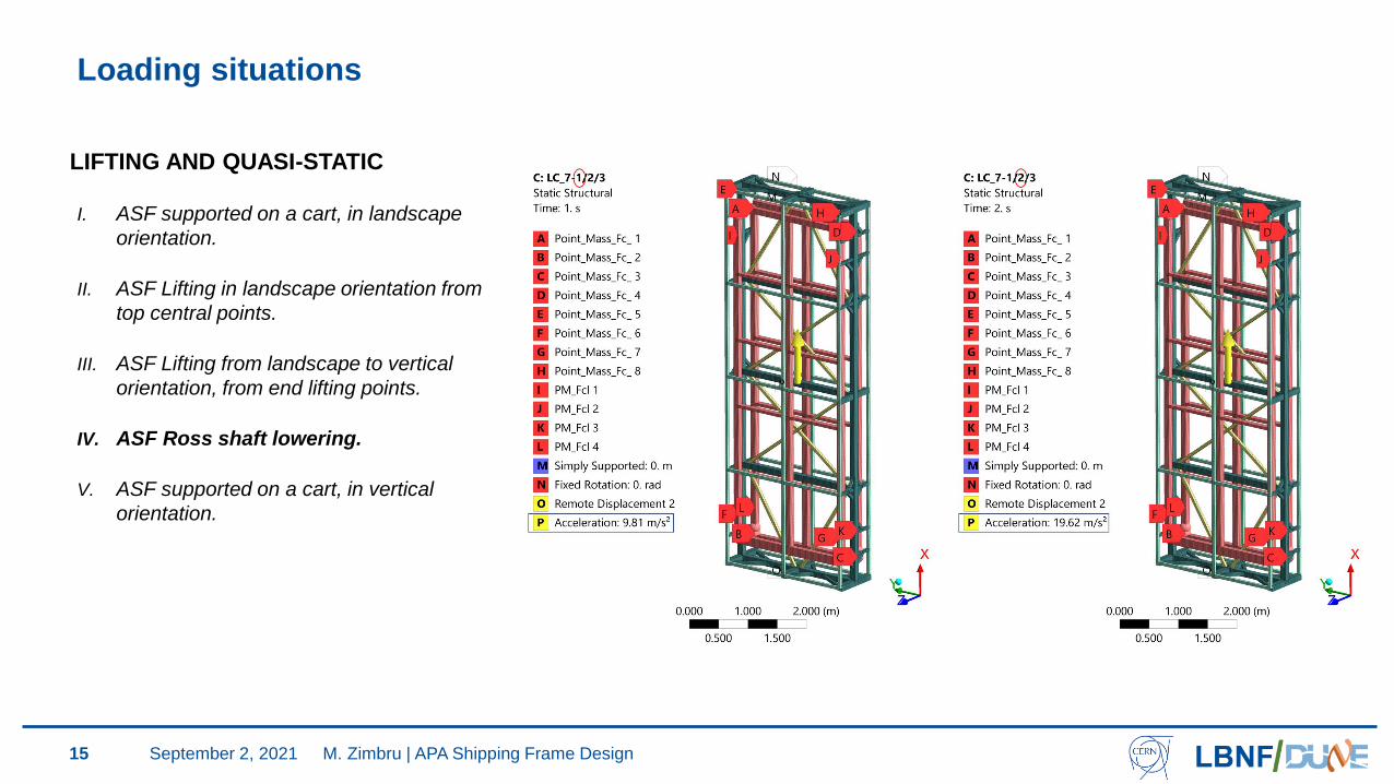
LIFTING AND QUASI-STATIC
I. ASF supported on a cart, in landscape
orientation.
II. ASF Lifting in landscape orientation from
top central points.
III. ASF Lifting from landscape to vertical
orientation, from end lifting points.
IV. ASF Ross shaft lowering.
V. ASF supported on a cart, in vertical
orientation.
M. Zimbru | APA Shipping Frame DesignSeptember 2, 2021
Loading situations
16
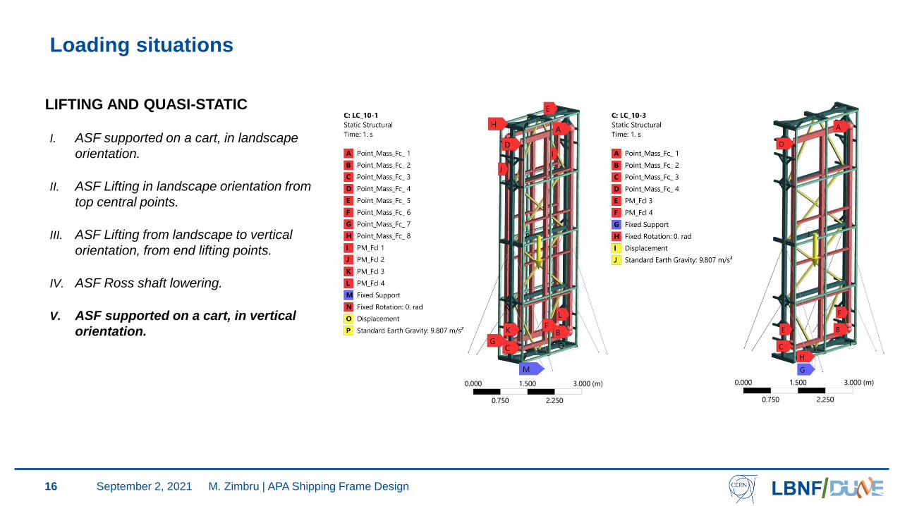
LIFTING AND QUASI-STATIC
I. ASF supported on a cart, in landscape
orientation.
II. ASF Lifting in landscape orientation from
top central points.
III. ASF Lifting from landscape to vertical
orientation, from end lifting points.
IV. ASF Ross shaft lowering.
V. ASF supported on a cart, in vertical
orientation.
M. Zimbru | APA Shipping Frame DesignSeptember 2, 2021
Loading situations
17
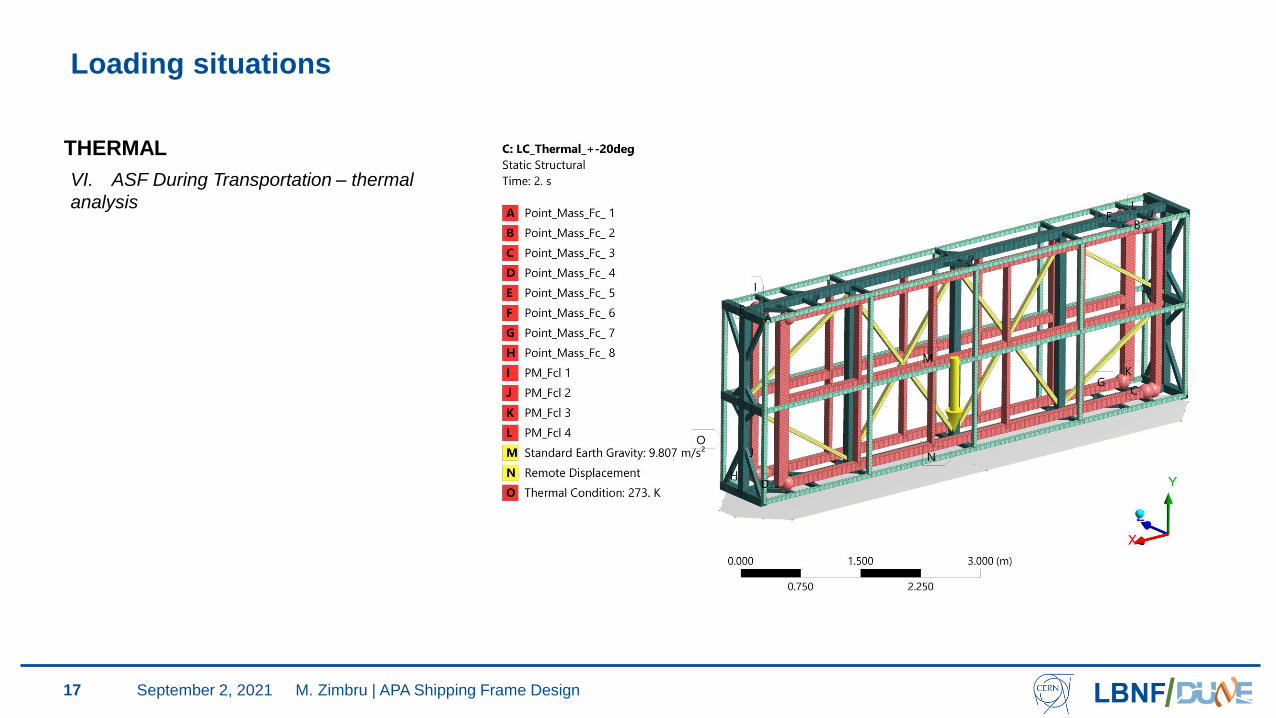
THERMAL
VI. ASF During Transportation – thermal
analysis
M. Zimbru | APA Shipping Frame DesignSeptember 2, 2021
Loading situations
18
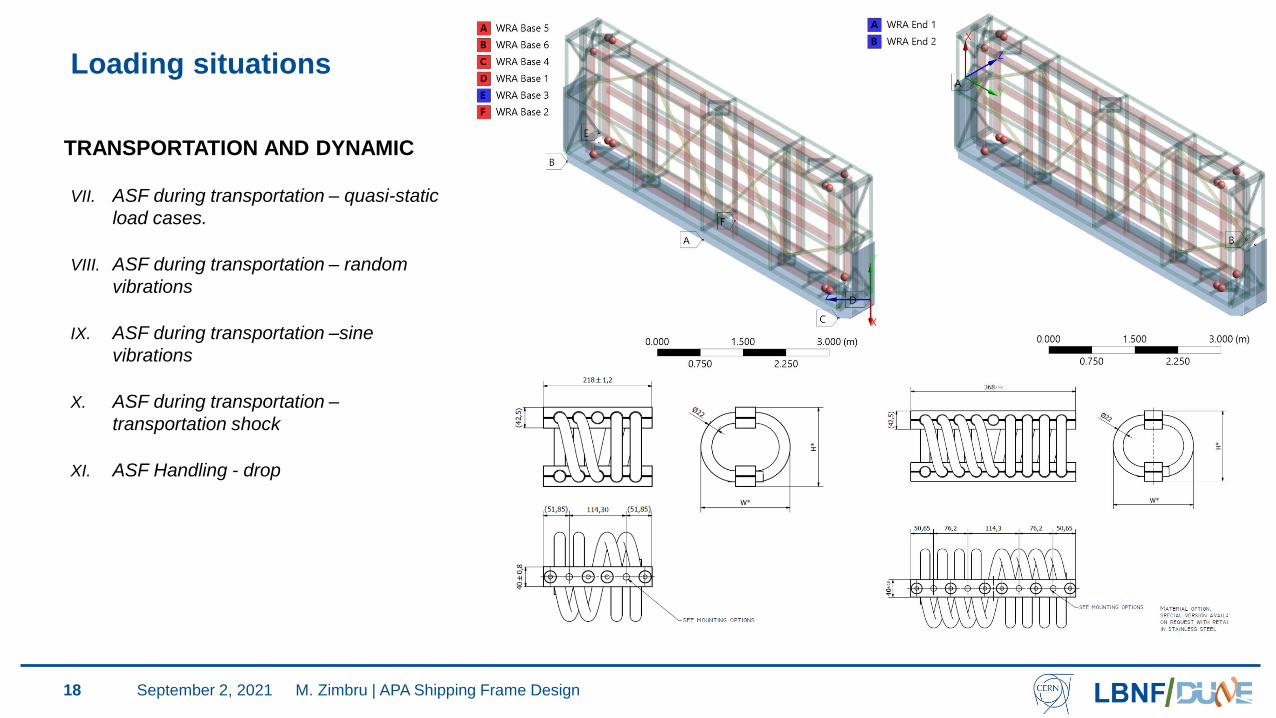
TRANSPORTATION AND DYNAMIC
VII. ASF during transportation – quasi-static
load cases.
VIII. ASF during transportation – random
vibrations
IX. ASF during transportation –sine
vibrations
X. ASF during transportation –
transportation shock
XI. ASF Handling - drop
M. Zimbru | APA Shipping Frame DesignSeptember 2, 2021
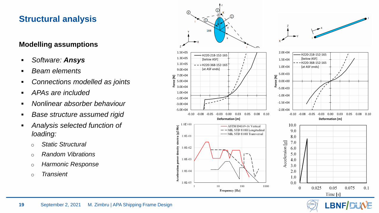
Structural analysis
19
-5.0E+04
-3.0E+04
-1.0E+04
1.0E+04
3.0E+04
5.0E+04
7.0E+04
9.0E+04
1.1E+05
1.3E+05
1.5E+05
-0.10 -0.08 -0.05 -0.03 0.00 0.03 0.05 0.08 0.10
Forc
e [
N]
Deformation [m]
H220-218-152-165[below ASF]
H220-368-152-165[at ASF ends]
-2.0E+04
-1.5E+04
-1.0E+04
-5.0E+03
0.0E+00
5.0E+03
1.0E+04
1.5E+04
2.0E+04
-0.10 -0.08 -0.05 -0.03 0.00 0.03 0.05 0.08 0.10
Forc
e [
N]
Deformation [m]
H220-218-152-165[below ASF]H220-368-152-165[at ASF ends]
Modelling assumptions
▪ Software: Ansys
▪ Beam elements
▪ Connections modelled as joints
▪ APAs are included
▪ Nonlinear absorber behaviour
▪ Base structure assumed rigid
▪ Analysis selected function of
loading:
o Static Structural
o Random Vibrations
o Harmonic Response
o Transient
M. Zimbru | APA Shipping Frame DesignSeptember 2, 2021

Design Requirements for the ASF (see previous presentation)
20
• To be easily handled in all lifting situations and able to withstand 1.5 x Static Load for
these cases (code requirement for lifting tools).
• Meet the requirements for critical lift
• To withstand dynamic inputs (accelerations, vibration, shock) and reduce their transfer
to the APAs
• To be able to withstand accidental cases (Ross shaft hoist failure, accidental drop)
• Protect from impacts and environmental effects
• Ease of access to the APA for verifications
• Ease of installation of the APA at the factory and removal inside the cavern
M. Zimbru | APA Shipping Frame DesignSeptember 2, 2021
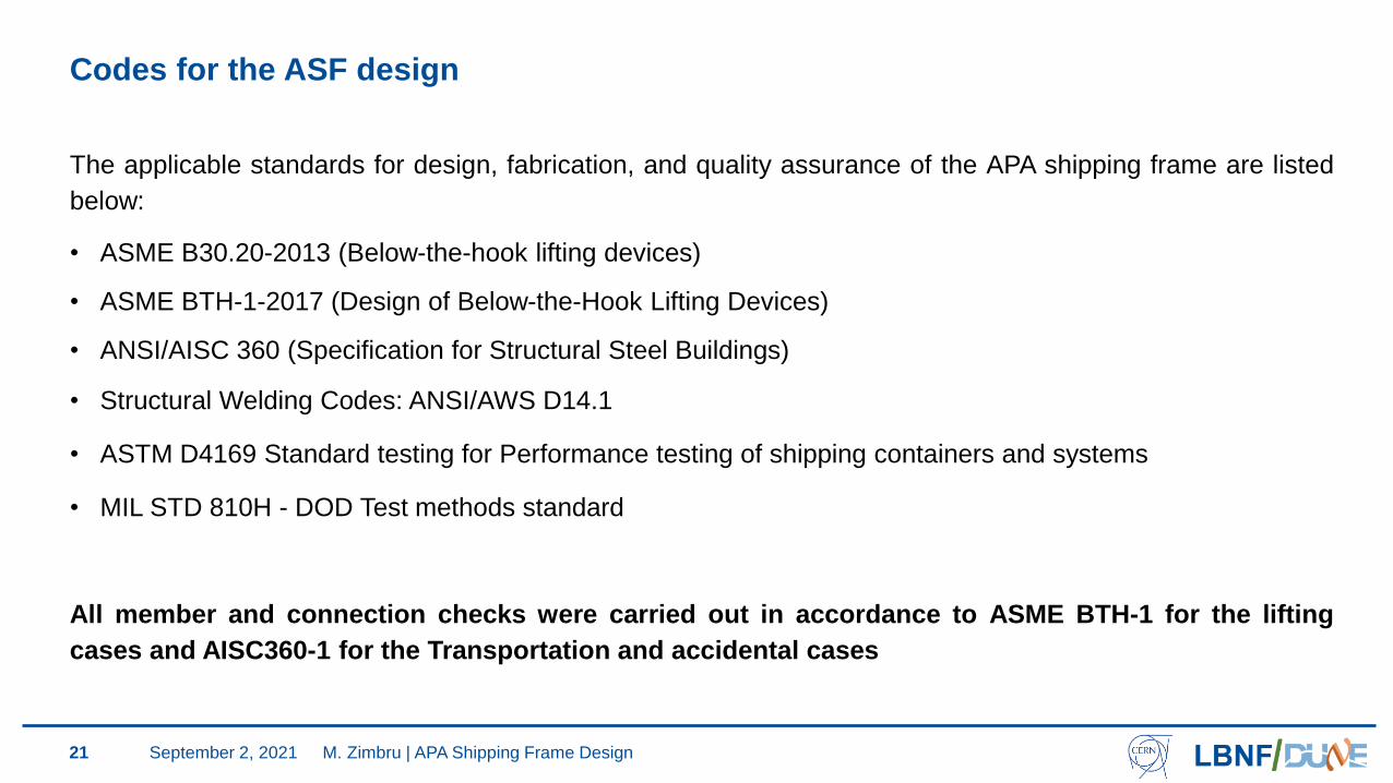
Codes for the ASF design
21
The applicable standards for design, fabrication, and quality assurance of the APA shipping frame are listed
below:
• ASME B30.20-2013 (Below-the-hook lifting devices)
• ASME BTH-1-2017 (Design of Below-the-Hook Lifting Devices)
• ANSI/AISC 360 (Specification for Structural Steel Buildings)
• Structural Welding Codes: ANSI/AWS D14.1
• ASTM D4169 Standard testing for Performance testing of shipping containers and systems
• MIL STD 810H - DOD Test methods standard
All member and connection checks were carried out in accordance to ASME BTH-1 for the lifting
cases and AISC360-1 for the Transportation and accidental cases
M. Zimbru | APA Shipping Frame DesignSeptember 2, 2021
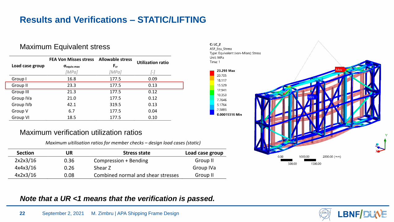
Results and Verifications – STATIC/LIFTING
22
Maximum Equivalent stress
Table 1 Maximum uitilisation ratios for member checks – design load cases (static)
Section UR Stress state Load case group
2x2x3/16 0.36 Compression + Bending Group II
4x4x3/16 0.26 Shear Z Group IVa
4x2x3/16 0.08 Combined normal and shear stresses Group II
Table 2 Maximum uitilisation ratios for member checks – accidental load case (static)
Section UR Stress state Load case group
2x2x3/16 0.19 Tension + Bending
Group IVb 4x4x3/16 0.28 Shear Z
4x2x3/16 0.02 Compression + Bending
Maximum verification utilization ratios
M. Zimbru | APA Shipping Frame Design
Note that a UR <1 means that the verification is passed.
September 2, 2021
Load case group
FEA Von Misses stress Allowable stress Utilization ratio
σequiv.max Fcr
[MPa] [MPa] [-]
Group I 16.8 177.5 0.09
Group II 23.3 177.5 0.13
Group III 21.3 177.5 0.12
Group IVa 21.0 177.5 0.12
Group IVb 42.1 319.5 0.13
Group V 6.7 177.5 0.04
Group VI 18.5 177.5 0.10

Results and Verifications – STATIC/LIFTING - Accidental
23
Load case group
FEA Von Misses stress Allowable stress Utilization ratio
σequiv.max Fcr
[MPa] [MPa] [-]
Group I 16.8 177.5 0.09
Group II 23.3 177.5 0.13
Group III 21.3 177.5 0.12
Group IVa 21.0 177.5 0.12
Group IVb 42.1 319.5 0.13
Group V 6.7 177.5 0.04
Group VI 18.5 177.5 0.10
Maximum Equivalent stress
Table 1 Maximum uitilisation ratios for member checks – design load cases (static)
Section UR Stress state Load case group
2x2x3/16 0.36 Compression + Bending Group II
4x4x3/16 0.26 Shear Z Group IVa
4x2x3/16 0.08 Combined normal and shear stresses Group II
Table 2 Maximum uitilisation ratios for member checks – accidental load case (static)
Section UR Stress state Load case group
2x2x3/16 0.19 Tension + Bending
Group IVb 4x4x3/16 0.28 Shear Z
4x2x3/16 0.02 Compression + Bending
Maximum verification utilization ratios
M. Zimbru | APA Shipping Frame Design
Note that a UR <1 means that the verification is passed.
September 2, 2021
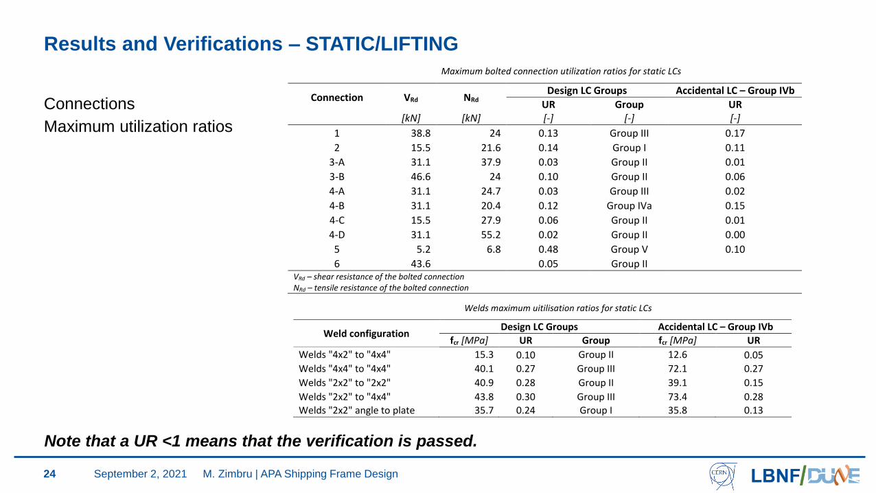
Results and Verifications – STATIC/LIFTING
24
Connections
Maximum utilization ratios
Table 1 Maximum bolted connection utilization ratios for static LCs
Connection VRd NRd Design LC Groups Accidental LC – Group IVb
UR Group UR
[kN] [kN] [-] [-] [-]
1 38.8 24 0.13 Group III 0.17
2 15.5 21.6 0.14 Group I 0.11
3-A 31.1 37.9 0.03 Group II 0.01
3-B 46.6 24 0.10 Group II 0.06
4-A 31.1 24.7 0.03 Group III 0.02
4-B 31.1 20.4 0.12 Group IVa 0.15
4-C 15.5 27.9 0.06 Group II 0.01
4-D 31.1 55.2 0.02 Group II 0.00
5 5.2 6.8 0.48 Group V 0.10
6 43.6 0.05 Group II VRd – shear resistance of the bolted connection NRd – tensile resistance of the bolted connection
Table 1 Welds maximum uitilisation ratios for static LCs
Weld configuration Design LC Groups Accidental LC – Group IVb
fcr [MPa] UR Group fcr [MPa] UR
Welds "4x2" to "4x4" 15.3 0.10 Group II 12.6 0.05
Welds "4x4" to "4x4" 40.1 0.27 Group III 72.1 0.27
Welds "2x2" to "2x2" 40.9 0.28 Group II 39.1 0.15
Welds "2x2" to "4x4" 43.8 0.30 Group III 73.4 0.28 Welds "2x2" angle to plate 35.7 0.24 Group I 35.8 0.13
M. Zimbru | APA Shipping Frame Design
Note that a UR <1 means that the verification is passed.
September 2, 2021
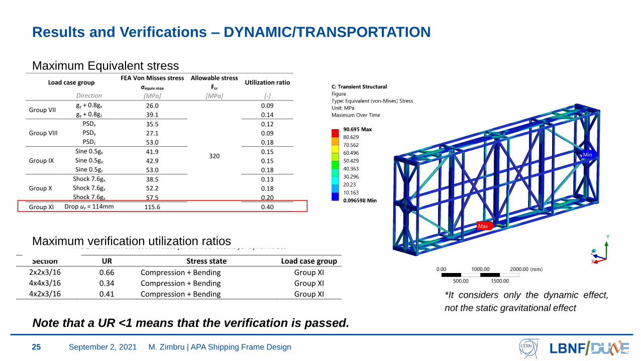
Results and Verifications – DYNAMIC/TRANSPORTATION
25
Maximum Equivalent stress
Maximum verification utilization ratios
Load case group FEA Von Misses stress Allowable stress
Utilization ratio σequiv.max Fcr
Direction [MPa] [MPa] [-]
Group VII gy + 0.8gx 26.0
320
0.09 gy + 0.8gz 39.1 0.14
Group VIII
PSDx 35.5 0.12 PSDy 27.1 0.09 PSDz 53.0 0.18
Group IX
Sine 0.5gx 41.9 0.15 Sine 0.5gy 42.9 0.15 Sine 0.5gz 53.0 0.18
Group X
Shock 7.6gx 38.5 0.13 Shock 7.6gx 52.2 0.18 Shock 7.6gx 57.5 0.20
Group XI Drop uy = 114mm 115.6 0.40
Table 1 Maximum uitilisation ratios for member checks for dynamic LCs
Section UR Stress state Load case group
2x2x3/16 0.66 Compression + Bending Group XI 4x4x3/16 0.34 Compression + Bending Group XI 4x2x3/16 0.41 Compression + Bending Group XI
*It considers only the dynamic effect,
not the static gravitational effect
M. Zimbru | APA Shipping Frame Design
Note that a UR <1 means that the verification is passed.
September 2, 2021
26
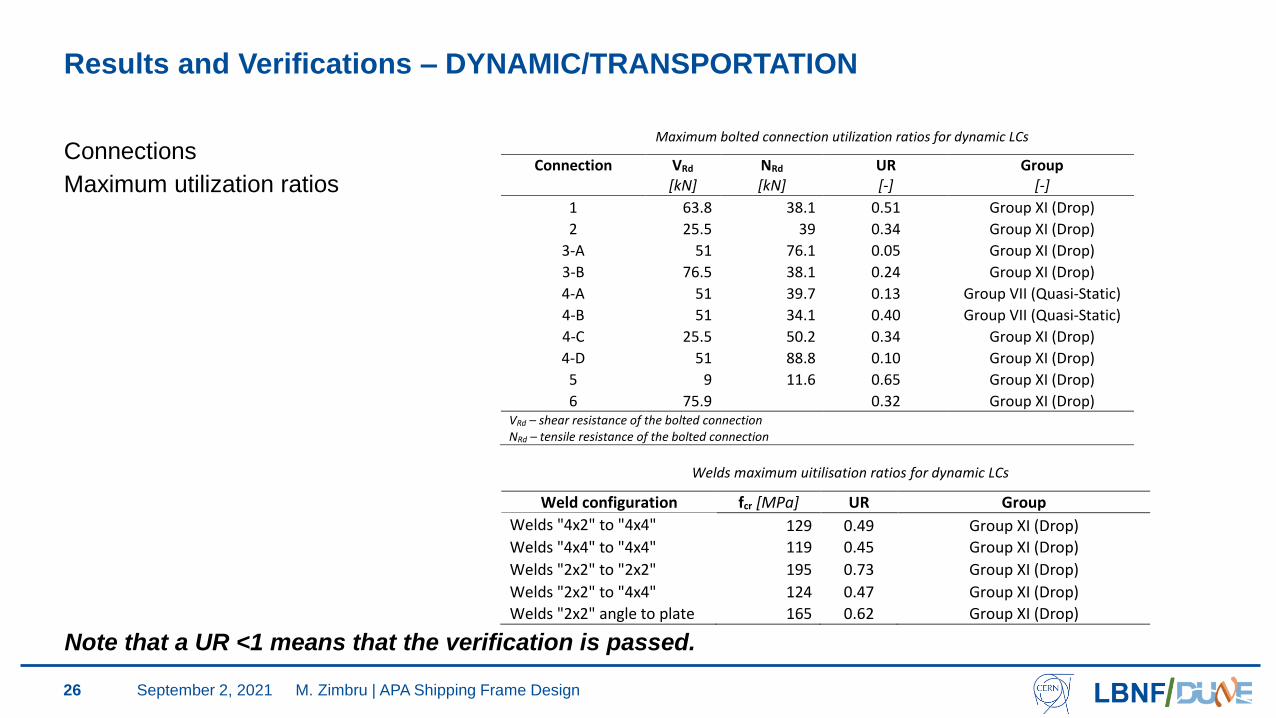
Results and Verifications – DYNAMIC/TRANSPORTATION
Connections
Maximum utilization ratios
Table 1 Maximum bolted connection utilization ratios for dynamic LCs
Connection VRd NRd UR Group
[kN] [kN] [-] [-]
1 63.8 38.1 0.51 Group XI (Drop)
2 25.5 39 0.34 Group XI (Drop)
3-A 51 76.1 0.05 Group XI (Drop)
3-B 76.5 38.1 0.24 Group XI (Drop)
4-A 51 39.7 0.13 Group VII (Quasi-Static)
4-B 51 34.1 0.40 Group VII (Quasi-Static)
4-C 25.5 50.2 0.34 Group XI (Drop)
4-D 51 88.8 0.10 Group XI (Drop)
5 9 11.6 0.65 Group XI (Drop)
6 75.9 0.32 Group XI (Drop) VRd – shear resistance of the bolted connection NRd – tensile resistance of the bolted connection
Table 1 Welds maximum uitilisation ratios for dynamic LCs
Weld configuration fcr [MPa] UR Group
Welds "4x2" to "4x4" 129 0.49 Group XI (Drop)
Welds "4x4" to "4x4" 119 0.45 Group XI (Drop)
Welds "2x2" to "2x2" 195 0.73 Group XI (Drop)
Welds "2x2" to "4x4" 124 0.47 Group XI (Drop)
Welds "2x2" angle to plate 165 0.62 Group XI (Drop)
M. Zimbru | APA Shipping Frame Design
Note that a UR <1 means that the verification is passed.
September 2, 2021
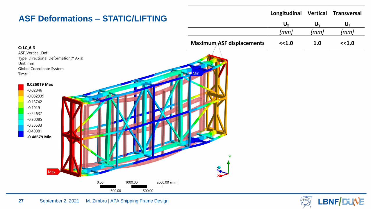
ASF Deformations – STATIC/LIFTING
27
Longitudinal
Ux
Vertical
Uy
Transversal
Uz
[mm] [mm] [mm]
Maximum ASF displacements <<1.0 1.0 <<1.0
M. Zimbru | APA Shipping Frame DesignSeptember 2, 2021
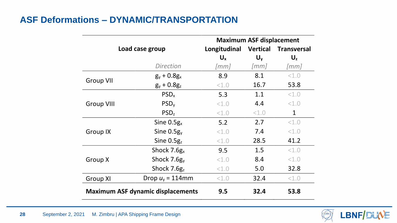
ASF Deformations – DYNAMIC/TRANSPORTATION
28
Load case group Maximum ASF displacement
Longitudinal Ux
Vertical Uy
Transversal Uz
Direction [mm] [mm] [mm]
Group VII gy + 0.8gx 8.9 8.1 <1.0
gy + 0.8gz <1.0 16.7 53.8
Group VIII
PSDx 5.3 1.1 <1.0
PSDy <1.0 4.4 <1.0
PSDz <1.0 <1.0 1
Group IX
Sine 0.5gx 5.2 2.7 <1.0
Sine 0.5gy <1.0 7.4 <1.0
Sine 0.5gz <1.0 28.5 41.2
Group X
Shock 7.6gx 9.5 1.5 <1.0
Shock 7.6gy <1.0 8.4 <1.0
Shock 7.6gz <1.0 5.0 32.8
Group XI Drop uy = 114mm <1.0 32.4 <1.0
Maximum ASF dynamic displacements 9.5 32.4 53.8
M. Zimbru | APA Shipping Frame DesignSeptember 2, 2021
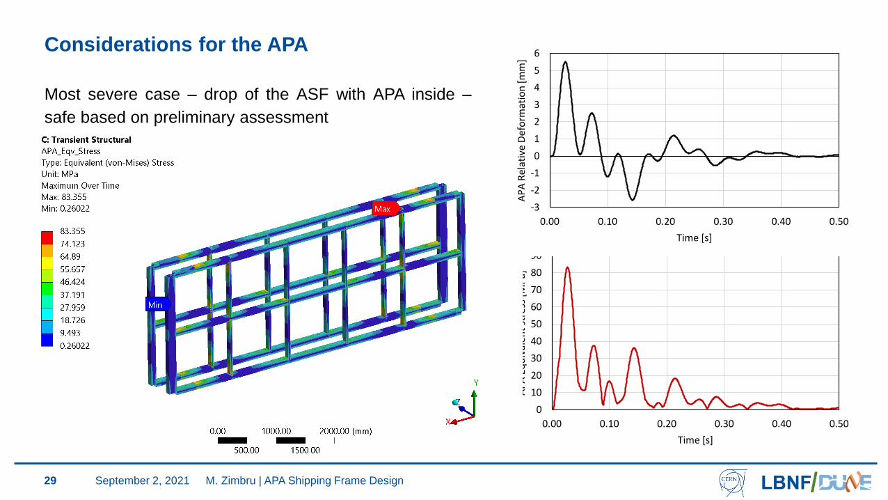
Considerations for the APA
29
0
10
20
30
40
50
60
70
80
90
0.00 0.10 0.20 0.30 0.40 0.50
AP
A E
qu
ival
ent
stre
ss [
MP
a]
Time [s]
-3
-2
-1
0
1
2
3
4
5
6
0.00 0.10 0.20 0.30 0.40 0.50
AP
A R
elat
ive
Def
orm
atio
n [m
m]
Time [s]
Most severe case – drop of the ASF with APA inside –
safe based on preliminary assessment
M. Zimbru | APA Shipping Frame DesignSeptember 2, 2021
Considerations for use
30
1. The analyzed boundary conditions must be replicated in reality for all cases (lifting, storage,
transportation)
2. The movement of the ASF in the factory, drift and cavern should be of such nature as not to
induce dynamic effects. Measures should be taken to mitigate such effects.
3. The handling of the APA Shipping Frame loaded with APA detectors must be treated as a
“critical lift” (DOE-STD-1090) in all circumstances.
M. Zimbru | APA Shipping Frame DesignSeptember 2, 2021
Conclusions
31
• The ASF design is deemed safe as all the member strength and stability, and connections
(welded and bolted) checks are met for all LCs.
• The APAs were part of the analyzed ASF model. Based on the verifications performed, the ASF
can safely hold, lift, and transport the APA detectors
• The AVMR assessment of the transportation assembly (ASF and absorbers) confirmed it meets
the safety requirements for transportation.
Note: The ASF was designed and verified based on the US codes for lifting and steel structures.
Another set of verifications was performed in accordance with the EU equivalent codes and very
similar results were obtained.
M. Zimbru | APA Shipping Frame DesignSeptember 2, 2021
Next steps
32
• An envelope study is being performed to verify the APA and shipping frame
• A prototype is being built at CERN (whcihc will be surveyed for execution tolerances) and two
are being built in the UK.
• A test plan is being developed
• The CERN prototype will be loaded with old ProtoDUNE APAs, instrumented and once tested, it
will be shipped to SURF
September 2, 2021 M. Zimbru | APA Shipping Frame Design