Embed Size (px)
Citation preview
Manufacturing Rev. 4, 8 (2017)© Z. Tao et al., Published by EDP Sciences 2017DOI: 10.1051/mfreview/2017010
Available online at:http://mfr.edp-open.org
RESEARCH ARTICLE
FE modeling of a complete warm-bending process for optimaldesign of heating stages for the forming of large-diameterthin-walled Ti–6Al–4V tubesZhijun Tao1, Heng Li1,*, Jun Ma1, Heng Yang1, Chao Lei1, and Guangjun Li2
1 State Key Laboratory of Solidification Processing, School of Materials Science and Engineering, NorthwesternPolytechnical University, Xi’an 710072, P.R. China
2 Chengdu Aircraft Industry (Group) Corporation Ltd., Chengdu 610092, P.R. China
� e-mail: l
This is an O
Received: 8 June 2017 / Accepted: 30 June 2017
Abstract. Warm rotary draw bending (WRDB) of large-diameter thin-walled (LDTW) Ti–6Al–4V tube is amulti-nonlinear thermo-mechanical coupled process. Due to the high-cost, energy-wasting and long-term, thetraditional physical experiments based on “trial and error” are no longer suitable for the WRBD process.Considering the non-uniform local heating and multi-tool constraints, a thermal–mechanical coupled 3D FEmodel of complete WRDB process for LDTW Ti–6Al–4V tube is established on ABAQUS as heating-bending-unloading three-stage. The FE models could predict the overall temperature distribution, describe thermo-mechanical bending deformation considering a modified Johnson–Cook model, and simulate the heating-bending-springback-cooling process. On that basis, the temperature distributions on both tube and dies undervarious heating schemes are compared, and the optimal heating scheme is determined on the basis of formingquality and efficiency. Combined with the experiments of WRDB, the optimal heating scheme and theestablished FE models are verified. In conclusion, the FE simulation provides a replacement of physicalexperiment and a convenient method of deformation prediction for WRDB of LDTW Ti–6Al–4V tube.
Keywords: warm rotary draw bending (WRDB) / complete process / FE modeling / heating scheme /parameter optimization / LDTW Ti–6Al–4V tube
1 Introduction
As one typical kind of light-weight and high-performancecomponents, large-diameter thin-walled (LDTW) Ti–6Al–4V bent tubes are urgently needed in many industries suchas aviation, aerospace, automobile and energy [1–4].Rotary draw bending, due to its advantages in achievinghigh-quality products and stable bending process, hasbecome an ideal approach for manufacturing LDTWtitanium tubes. However, constrained by the limitedformability of LDTW Ti–6Al–4V tube, cracking andwrinkling are the incredible problems during cold bending[5–8]. Warm-bending (room temperature<Tw< recrystal-lization temperature) may be a feasible way formanufacturing these components [9,10].
Warm rotary draw bending (WRDB) of Ti–6Al–4Vtube is a complex thermo-mechanical coupled plasticforming process with multi-tool constraints and multi-
pen Access article distributed under the terms of the Creative Comwhich permits unrestricted use, distribution, and reproduction
factor interacted effects. Among them, temperature fieldsis one of the most important issue affecting the materialproperties and bending process, which directly determineswhether the Ti–6Al–4V bent tubular parts can be achievedor not. Increasing working temperature leads to thereduction of deformation resistance and the improvementof formability in many metal forming processes, such asaluminum, magnesium and commercial pure titanium.With the increase of temperature, the decreased flow stressreduces the deformation resistance of Ti–6Al–4V tube,which is helpful for the flow of the tube material. Forexample, the flow stress has an obvious drop of about 50%at temperature increasing to 873K [9]. However, theelevated temperatures also strengthen the constrainteffects of the bending dies. Meanwhile, different heatingstrategies of each bending dies will result in the differenttemperature distribution on Ti–6Al–4V tube, which has asignificant effect on the non-uniform temperature con-trolled warm-bending process. As a result, the couplingeffects of thermal and mechanical parameters make thebending deformation even more complex. Therefore, it is
mons Attribution License (http://creativecommons.org/licenses/by/4.0),in any medium, provided the original work is properly cited.
2 Z. Tao et al.: Manufacturing Rev. 4, 8 (2017)
urgent to investigate the temperature related bendabilityof WRDB for Ti–6Al–4V tube to prevent the possibledefects, and the effect of reasonable temperature distribu-tion on forming properties to improve the bending quality.
To date, numerous efforts have been conducted toinvestigate the deformation behaviors and formability oftitanium sheets and bars at elevated temperatures.Kotkunde et al. [11] proposed a set of isothermal uniaxialtests of Ti–6Al–4V flat-sheet samples at temperature rangefrom room temperature up to 650 °C, and noticed thecomplicated interaction between strain hardening andthermal effects. Compared with room temperature condi-tion, approximately half the ultimate tensile stress andtwice the maximum strain of Ti–6Al–4V are achieved at650 °C, as proved by Lai et al. [12]. Chen et al. [13] studiedthe temperature dependent work hardening in Ti–6Al–4Valloy over large temperature range (20–900 °C). Therefore,it can be seen that bending at elevated temperature can becarried out to form LDTWTi–6Al–4V bent tubes.Wu et al.[14] found that heating could improve the bending ability ofwrought magnesium alloy AM30 tubes using a rotary drawbender at 473K and bending velocity of 8mm/s. Luo et al.[15] also proved that it was feasible to bendmagnesium alloyAZ31 tubes at elevated temperature (423–473K). Jin et al.[16] showed thedeformationmechanismsofmagnesiumtubebending at elevated temperature. Zhang et al. [17] studiedthe quasi-static tensile behavior of LDTW CP-Ti tubes atvarious temperature ranges and different strain rates, andachieved that the optimal temperature for tube warm-bending is 573K. All of above studies have laid thegroundwork for Ti–6Al–4V tube warm-bending.
However, WRDB of LDTWTi–6Al–4V tube is a highlynonlinear unstable forming process including multipleconstraints and complex thermal–mechanical couplingeffects, which is quite difficultly studied and needs largecost consuming by using experimental. In the last twodecades, FE simulation has become an increasing impor-tant tool for investigating metal forming processes [18–20].FE simulation can provide convenience not only to makeclear the forming mechanisms, temperature effects, tracesof deformation, microstructure evolutions and an insightinto how defects arise during the forming process, but alsoto give an efficient method to identify and optimizeimportant process parameters without expensive experi-ments [21–24]. Therefore, it’s important to develop areasonable FE model for the investigation and understand-ing of tube warm-bending, which should be as consistentwith the real conditions as possible and can savecomputation time.
Many scholars have studied the tube bending bycombining the FE method with the experimental andanalytical methods, especially applied to aluminum alloytube and stainless steel tube [25–29]. Reliable FE models ofcold tube bending were established so as to analyze stressand strain distribution, predict instability wrinklingbehavior, solve springback problem, optimize processparameters and obtain qualified bent tube. Jiang et al.[30,31] established bending-springback FE model oftitanium tube cold bending. Trana [32] studied the bendingprocess of high strength steel tube by combining FEsimulation and experiment. Till now, the FE simulation
method has been applied on various tube heating bendingprocesses. Zhang et al. [33] provide useful knowledge for theFE modeling of warm-bending and the realization of theprecision bending of LDTW CP-Ti tubes. Hu et al. [34,35]established a local induction heat bending model of steeltube with small bending radius. Zhou et al. [36] establisheda hot push bending model of TA2 ring pipe. Li et al. [37]simulated a medium frequency induction heating bendingprocess of pure titanium tube. Dai et al. [38] simulated a hotpush bending process of Ti–6Al–4V tube. The abovestudies lay the foundation and prove the feasibility of Ti–6Al–4V tube warm-bending.
To further study the forming rules of WRDB andachieve excellent bent tube of Ti–6Al–4V alloy, this paperproposed a complete process model of heating-bending-unloading, and then focused on the optimal design ofheating system to achieve the reasonable temperaturedistribution. Then, the FE model of warm-bending isestablished and used to predict wall thinning, wrinklingand cross-section distortion and even fracture. The optimalheating method could establish a sound preliminarythermal condition to improve heat bending formabilityand reduce energy consumption.
2 FE modeling of complete warm-bendingprocess
2.1 Characteristics of WRDB for Ti–6Al–4V tube
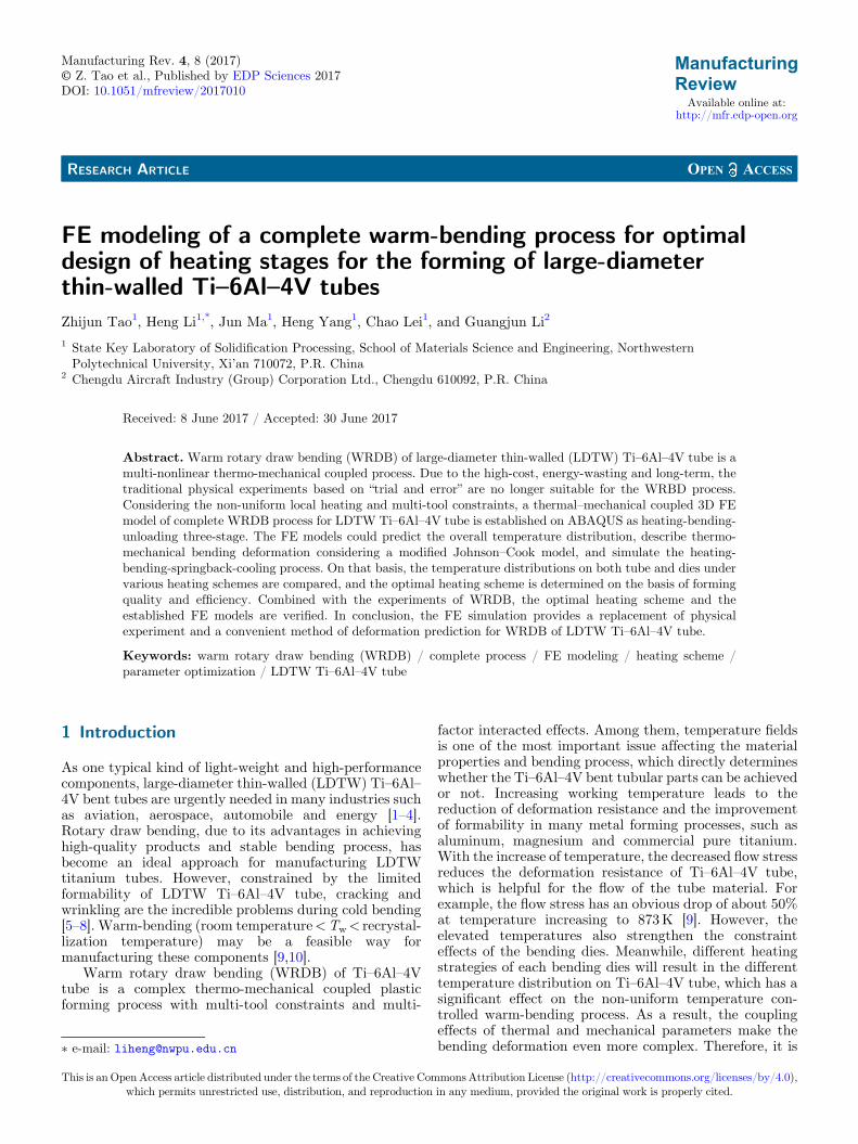
In order to obtain precision LDTWTi–6Al–4V bent tubes,a group of heating resistors is applied on different parts ofthe die system to make tubes be heated to requiredtemperature of warm-bending. Then the tube is clampedby clamp die and bend die to finish rotary draw bendingwith the helpful push of pressure die. Finally, all of the diesunload after the bending angle satisfied the request, andthen the bent tube will springback. However, due to theoriginal defect, the performance of Ti–6Al–4V tube is non-linearity. The bending process is operated by multi-dieswhich will lead to non-linearity of contacts and boundaryconditions. The uneven deformation of Ti–6Al–4V tubeleads to complex geometrical nonlinearity. The coupling ofthe temperature field and the stress field in the process ofdeformation makes the bending deformation more compli-cated. As a result, under the superimposed effect of uneventemperature field and stress field, tube warm-bending isextremely complex (Fig. 1). If the forming parameters arenot properly chosen, instability of bending process such aswrinkling, cross section distortion and fracture, will occurand get out of hand.
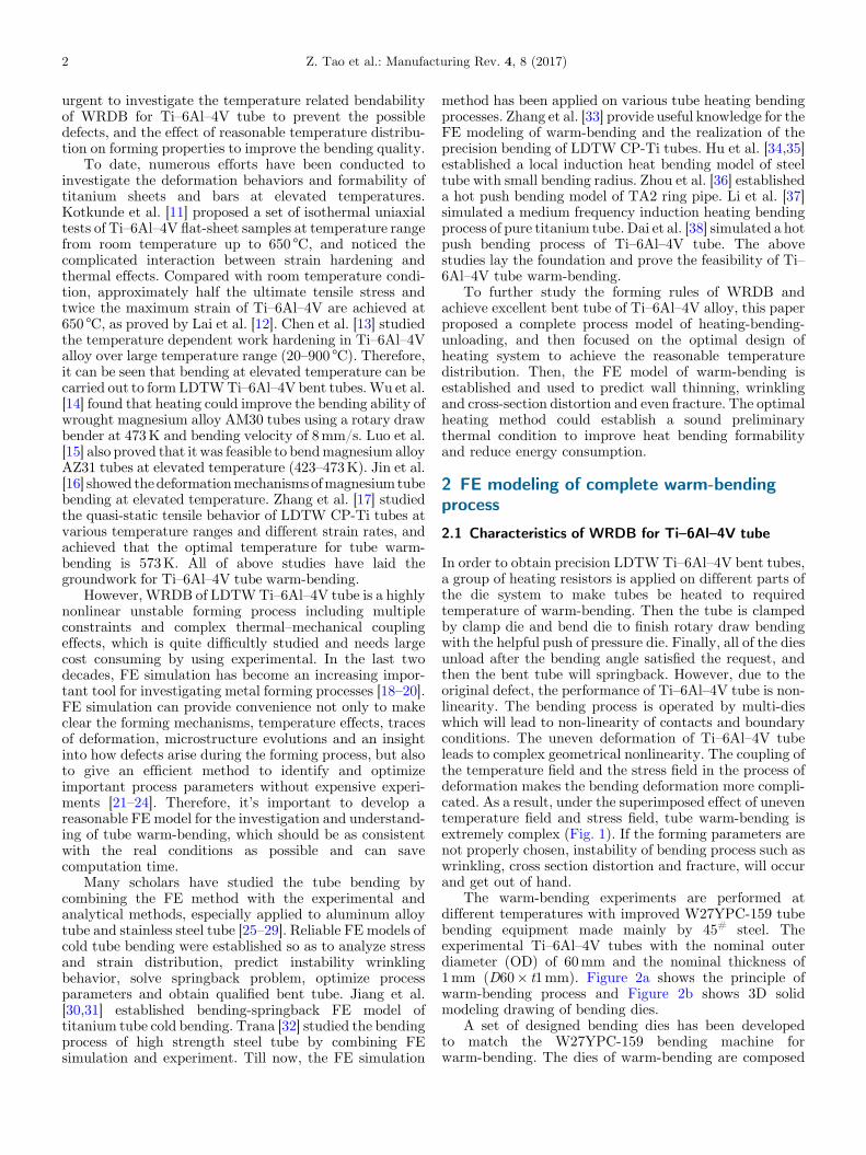
The warm-bending experiments are performed atdifferent temperatures with improved W27YPC-159 tubebending equipment made mainly by 45# steel. Theexperimental Ti–6Al–4V tubes with the nominal outerdiameter (OD) of 60mm and the nominal thickness of1mm (D60� t1mm). Figure 2a shows the principle ofwarm-bending process and Figure 2b shows 3D solidmodeling drawing of bending dies.
A set of designed bending dies has been developedto match the W27YPC-159 bending machine forwarm-bending. The dies of warm-bending are composed
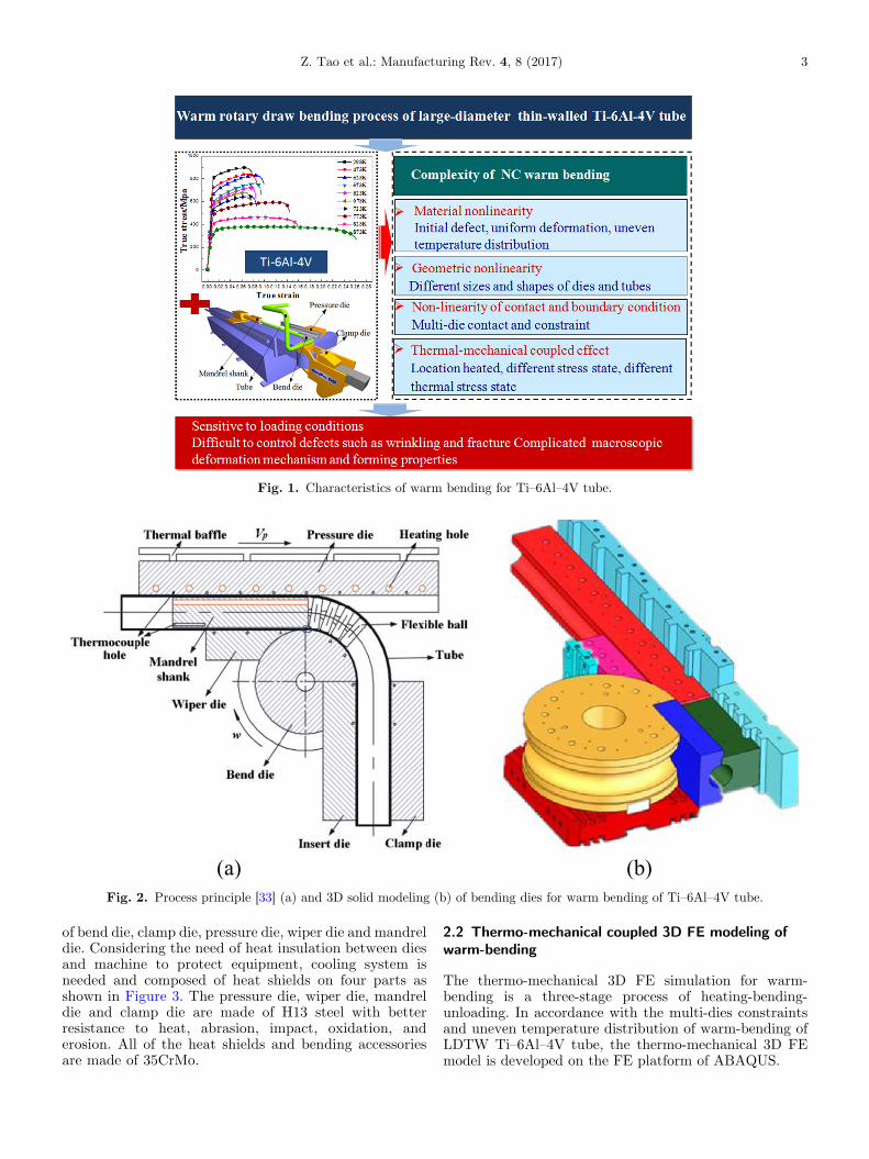
Fig. 1. Characteristics of warm bending for Ti–6Al–4V tube.
(a) (b)Fig. 2. Process principle [33] (a) and 3D solid modeling (b) of bending dies for warm bending of Ti–6Al–4V tube.
Z. Tao et al.: Manufacturing Rev. 4, 8 (2017) 3
of bend die, clamp die, pressure die, wiper die and mandreldie. Considering the need of heat insulation between diesand machine to protect equipment, cooling system isneeded and composed of heat shields on four parts asshown in Figure 3. The pressure die, wiper die, mandreldie and clamp die are made of H13 steel with betterresistance to heat, abrasion, impact, oxidation, anderosion. All of the heat shields and bending accessoriesare made of 35CrMo.
2.2 Thermo-mechanical coupled 3D FE modeling ofwarm-bending
The thermo-mechanical 3D FE simulation for warm-bending is a three-stage process of heating-bending-unloading. In accordance with the multi-dies constraintsand uneven temperature distribution of warm-bending ofLDTW Ti–6Al–4V tube, the thermo-mechanical 3D FEmodel is developed on the FE platform of ABAQUS.
(a) (b)Fig. 3. Cooling system for warm bending of Ti–6Al–4V tube: (a) assembly drawing and (b) constituent parts (1 – heat shield ofpressure die, 2 – heat shield of wiper die, 3 – heat shield of clamp die, 4 – heat shield of bend die, 5 – water outlet port, 6 – water inletport, 7 – water tank, 8 – electrical power machine, 9 – controller, 10 – water pipe).
Fig. 4. 3D-FE geometric model and mesh partition for heating stage.
Table 1. Grid size at different locations of FE geometric model during heating stage.
Location Tube, mandrel shank,flexible ball
Bend die holder Joint of flexibleball
Other dies
Grid size (mm2) 5� 5 15� 15 3� 3 10� 10
4 Z. Tao et al.: Manufacturing Rev. 4, 8 (2017)
2.2.1 Key techniques for 3D FE modeling of heating stage
The heating stage of warm-bending of LDTW Ti–6Al–4Vtube is a static heat transfer process, so the ABAQUS/Standard module is employed to discretize the geometricmodel into heat conduction unit with heat-transfer analysisstep option. As the same time, the transient analysis step isused for the heating stage that is time-dependent.
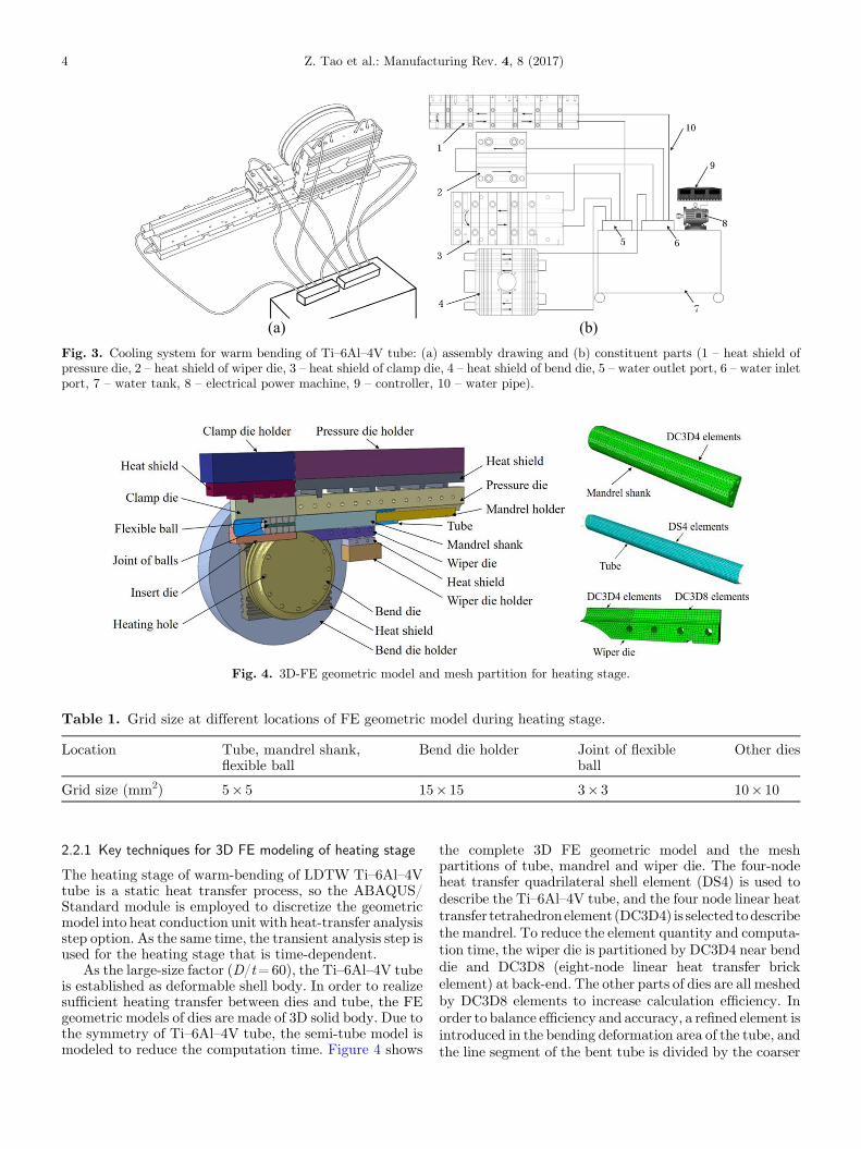
As the large-size factor (D/t=60), the Ti–6Al–4V tubeis established as deformable shell body. In order to realizesufficient heating transfer between dies and tube, the FEgeometric models of dies are made of 3D solid body. Due tothe symmetry of Ti–6Al–4V tube, the semi-tube model ismodeled to reduce the computation time. Figure 4 shows
the complete 3D FE geometric model and the meshpartitions of tube, mandrel and wiper die. The four-nodeheat transfer quadrilateral shell element (DS4) is used todescribe the Ti–6Al–4V tube, and the four node linear heattransfer tetrahedronelement(DC3D4) is selected todescribethe mandrel. To reduce the element quantity and computa-tion time, the wiper die is partitioned by DC3D4 near benddie and DC3D8 (eight-node linear heat transfer brickelement) at back-end. The other parts of dies are all meshedby DC3D8 elements to increase calculation efficiency. Inorder to balance efficiency and accuracy, a refined element isintroduced in the bending deformation area of the tube, andthe line segment of the bent tube is divided by the coarser
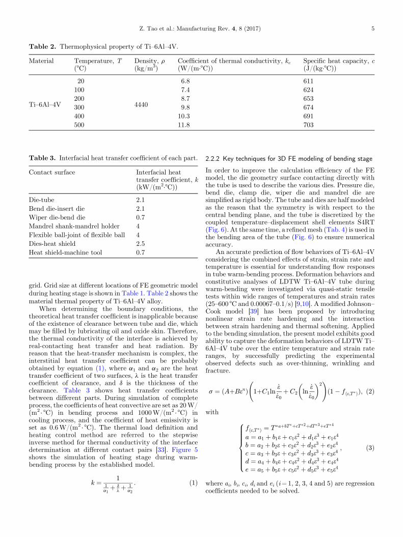
Table 2. Thermophysical property of Ti–6Al–4V.
Material Temperature, T(°C)
Density, r(kg/m3)
Coefficient of thermal conductivity, kc(W/(m·°C))
Specific heat capacity, c(J/(kg·°C))
Ti–6Al–4V
20
4440
6.8 611100 7.4 624200 8.7 653300 9.8 674400 10.3 691500 11.8 703
Table 3. Interfacial heat transfer coefficient of each part.
Contact surface Interfacial heattransfer coefficient, k(kW/(m2·°C))
Die-tube 2.1Bend die-insert die 2.1Wiper die-bend die 0.7Mandrel shank-mandrel holder 4Flexible ball-joint of flexible ball 4Dies-heat shield 2.5Heat shield-machine tool 0.7
Z. Tao et al.: Manufacturing Rev. 4, 8 (2017) 5
grid. Grid size at different locations of FE geometric modelduring heating stage is shown in Table 1. Table 2 shows thematerial thermal property of Ti–6Al–4V alloy.
When determining the boundary conditions, thetheoretical heat transfer coefficient is inapplicable becauseof the existence of clearance between tube and die, whichmay be filled by lubricating oil and oxide skin. Therefore,the thermal conductivity of the interface is achieved byreal-contacting heat transfer and heat radiation. Byreason that the heat-transfer mechanism is complex, theinterstitial heat transfer coefficient can be probablyobtained by equation (1), where a1 and a2 are the heattransfer coefficient of two surfaces, l is the heat transfercoefficient of clearance, and d is the thickness of theclearance. Table 3 shows heat transfer coefficientsbetween different parts. During simulation of completeprocess, the coefficients of heat convective are set as 20W/(m2 · °C) in bending process and 1000W/(m2 · °C) incooling process, and the coefficient of heat emissivity isset as 0.6W/(m2 · °C). The thermal load definition andheating control method are referred to the stepwiseinverse method for thermal conductivity of the interfacedetermination at different contact pairs [33]. Figure 5shows the simulation of heating stage during warm-bending process by the established model.
k ¼ 11a1þ d
lþ 1
a2
: ð1Þ
2.2.2 Key techniques for 3D FE modeling of bending stage
In order to improve the calculation efficiency of the FEmodel, the die geometry surface contacting directly withthe tube is used to describe the various dies. Pressure die,bend die, clamp die, wiper die and mandrel die aresimplified as rigid body. The tube and dies are half modeledas the reason that the symmetry is with respect to thecentral bending plane, and the tube is discretized by thecoupled temperature–displacement shell elements S4RT(Fig. 6). At the same time, a refinedmesh (Tab. 4) is used inthe bending area of the tube (Fig. 6) to ensure numericalaccuracy.
An accurate prediction of flow behaviors of Ti–6Al–4Vconsidering the combined effects of strain, strain rate andtemperature is essential for understanding flow responsesin tube warm-bending process. Deformation behaviors andconstitutive analyses of LDTW Ti–6Al–4V tube duringwarm-bending were investigated via quasi-static tensiletests within wide ranges of temperatures and strain rates(25–600 °C and 0.00067–0.1/s) [9,10]. A modified Johnson–Cook model [39] has been proposed by introducingnonlinear strain rate hardening and the interactionbetween strain hardening and thermal softening. Appliedto the bending simulation, the present model exhibits goodability to capture the deformation behaviors of LDTWTi–6Al–4V tube over the entire temperature and strain rateranges, by successfully predicting the experimentalobserved defects such as over-thinning, wrinkling andfracture.
s ¼ ðAþBenÞ 1þC1ln
.e.e0
þ C2 ln
.e.e0
� �2 !
ð1� fðe;T�ÞÞ; ð2Þ
with
fðe;T�Þ ¼ T �aþbT�þcT�2þdT�3þeT�4
a ¼ a1 þ b1eþ c1e2 þ d1e3 þ e1e4
b ¼ a2 þ b2eþ c2e2 þ d2e3 þ e2e4
c ¼ a3 þ b3eþ c3e2 þ d3e3 þ e3e4
d ¼ a4 þ b4eþ c4e2 þ d4e3 þ e4e4
e ¼ a5 þ b5eþ c5e2 þ d5e3 þ e5e4
;
8>>>>>><>>>>>>:
ð3Þ
where ai, bi, ci, di and ei (i=1, 2, 3, 4 and 5) are regressioncoefficients needed to be solved.
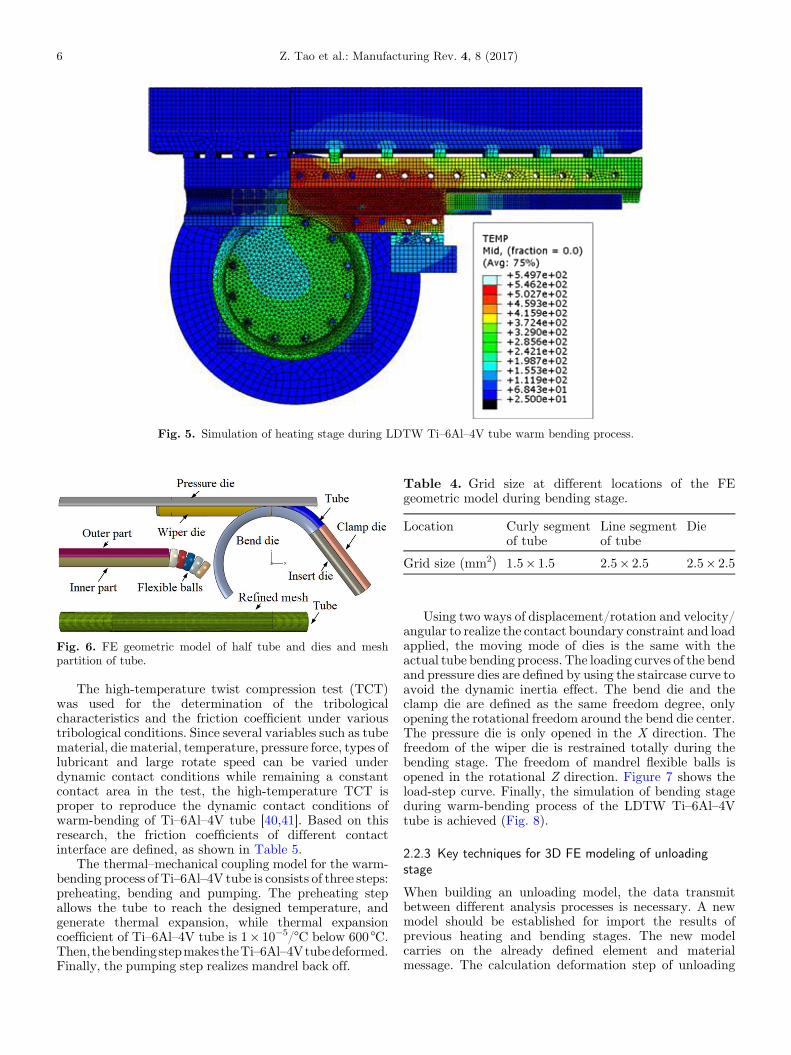
Fig. 5. Simulation of heating stage during LDTW Ti–6Al–4V tube warm bending process.
Fig. 6. FE geometric model of half tube and dies and meshpartition of tube.
Table 4. Grid size at different locations of the FEgeometric model during bending stage.
Location Curly segmentof tube
Line segmentof tube
Die
Grid size (mm2) 1.5� 1.5 2.5� 2.5 2.5� 2.5
6 Z. Tao et al.: Manufacturing Rev. 4, 8 (2017)
The high-temperature twist compression test (TCT)was used for the determination of the tribologicalcharacteristics and the friction coefficient under varioustribological conditions. Since several variables such as tubematerial, die material, temperature, pressure force, types oflubricant and large rotate speed can be varied underdynamic contact conditions while remaining a constantcontact area in the test, the high-temperature TCT isproper to reproduce the dynamic contact conditions ofwarm-bending of Ti–6Al–4V tube [40,41]. Based on thisresearch, the friction coefficients of different contactinterface are defined, as shown in Table 5.
The thermal–mechanical coupling model for the warm-bending process of Ti–6Al–4V tube is consists of three steps:preheating, bending and pumping. The preheating stepallows the tube to reach the designed temperature, andgenerate thermal expansion, while thermal expansioncoefficient of Ti–6Al–4V tube is 1� 10�5/°C below 600 °C.Then,thebendingstepmakestheTi–6Al–4Vtubedeformed.Finally, the pumping step realizes mandrel back off.
Using two ways of displacement/rotation and velocity/angular to realize the contact boundary constraint and loadapplied, the moving mode of dies is the same with theactual tube bending process. The loading curves of the bendand pressure dies are defined by using the staircase curve toavoid the dynamic inertia effect. The bend die and theclamp die are defined as the same freedom degree, onlyopening the rotational freedom around the bend die center.The pressure die is only opened in the X direction. Thefreedom of the wiper die is restrained totally during thebending stage. The freedom of mandrel flexible balls isopened in the rotational Z direction. Figure 7 shows theload-step curve. Finally, the simulation of bending stageduring warm-bending process of the LDTW Ti–6Al–4Vtube is achieved (Fig. 8).
2.2.3 Key techniques for 3D FE modeling of unloadingstage
When building an unloading model, the data transmitbetween different analysis processes is necessary. A newmodel should be established for import the results ofprevious heating and bending stages. The new modelcarries on the already defined element and materialmessage. The calculation deformation step of unloading
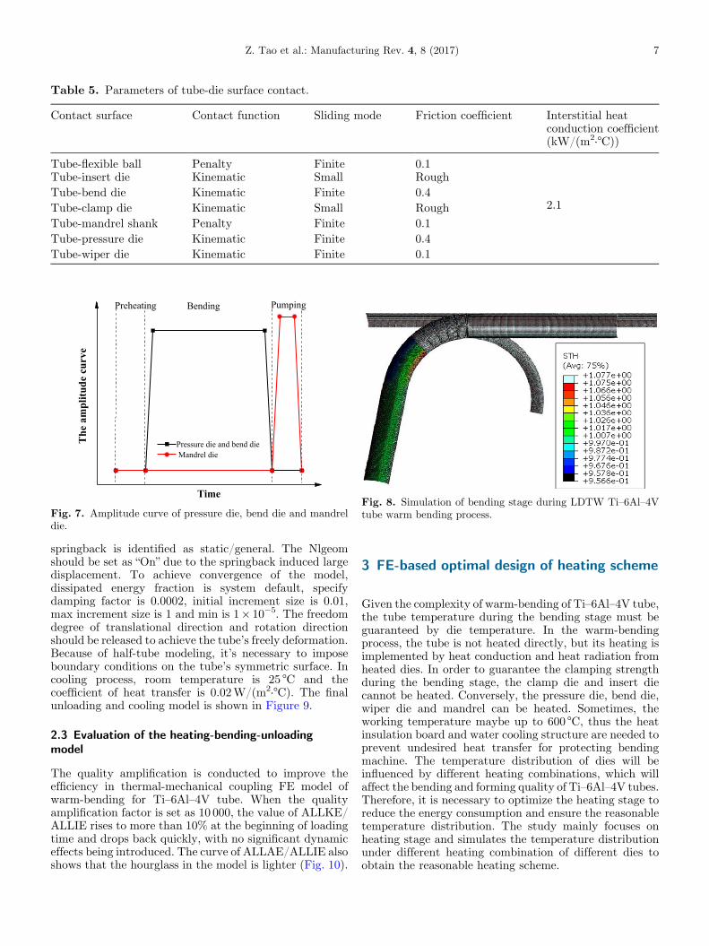
Table 5. Parameters of tube-die surface contact.
Contact surface Contact function Sliding mode Friction coefficient Interstitial heatconduction coefficient(kW/(m2·°C))
Tube-flexible ball Penalty Finite 0.1
2.1
Tube-insert die Kinematic Small RoughTube-bend die Kinematic Finite 0.4Tube-clamp die Kinematic Small RoughTube-mandrel shank Penalty Finite 0.1Tube-pressure die Kinematic Finite 0.4Tube-wiper die Kinematic Finite 0.1
Pressure die and bend die Mandrel die
PumpingBending
evrucedutilp
maeh
T
Time
Preheating
Fig. 7. Amplitude curve of pressure die, bend die and mandreldie.
Fig. 8. Simulation of bending stage during LDTW Ti–6Al–4Vtube warm bending process.
Z. Tao et al.: Manufacturing Rev. 4, 8 (2017) 7
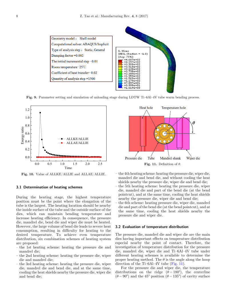
springback is identified as static/general. The Nlgeomshould be set as “On” due to the springback induced largedisplacement. To achieve convergence of the model,dissipated energy fraction is system default, specifydamping factor is 0.0002, initial increment size is 0.01,max increment size is 1 and min is 1� 10�5. The freedomdegree of translational direction and rotation directionshould be released to achieve the tube’s freely deformation.Because of half-tube modeling, it’s necessary to imposeboundary conditions on the tube’s symmetric surface. Incooling process, room temperature is 25 °C and thecoefficient of heat transfer is 0.02W/(m2·°C). The finalunloading and cooling model is shown in Figure 9.
2.3 Evaluation of the heating-bending-unloadingmodel
The quality amplification is conducted to improve theefficiency in thermal-mechanical coupling FE model ofwarm-bending for Ti–6Al–4V tube. When the qualityamplification factor is set as 10 000, the value of ALLKE/ALLIE rises to more than 10% at the beginning of loadingtime and drops back quickly, with no significant dynamiceffects being introduced. The curve of ALLAE/ALLIE alsoshows that the hourglass in the model is lighter (Fig. 10).
3 FE-based optimal design of heating scheme
Given the complexity of warm-bending of Ti–6Al–4V tube,the tube temperature during the bending stage must beguaranteed by die temperature. In the warm-bendingprocess, the tube is not heated directly, but its heating isimplemented by heat conduction and heat radiation fromheated dies. In order to guarantee the clamping strengthduring the bending stage, the clamp die and insert diecannot be heated. Conversely, the pressure die, bend die,wiper die and mandrel can be heated. Sometimes, theworking temperature maybe up to 600 °C, thus the heatinsulation board and water cooling structure are needed toprevent undesired heat transfer for protecting bendingmachine. The temperature distribution of dies will beinfluenced by different heating combinations, which willaffect the bending and forming quality of Ti–6Al–4V tubes.Therefore, it is necessary to optimize the heating stage toreduce the energy consumption and ensure the reasonabletemperature distribution. The study mainly focuses onheating stage and simulates the temperature distributionunder different heating combination of different dies toobtain the reasonable heating scheme.
0.0 0.5 1.0 1.5 2.0 2.5
0.0
0.2
0.4
0.6
0.8
1.0
1.2
oitarygrenE
Time
ALLKE/ALLIE ALLAE/ALLIE
Fig. 10. Value of ALLKE/ALLIE and ALLAE/ALLIE.
Fig. 11. Definition of u.
Fig. 9. Parameter setting and simulation of unloading stage during LDTW Ti–6Al–4V tube warm bending process.
8 Z. Tao et al.: Manufacturing Rev. 4, 8 (2017)
3.1 Determination of heating schemes
During the heating stage, the highest temperatureposition must be the point where the elongation of thetube is the largest. The heating location should be nearbythe inside surface of the tube and the outside surface of thedies, which can maintain bending temperature andincrease heating efficiency. In consequence, the pressuredie, mandrel die, bend die and wiper die must be heated.However, the large volume of bend die leads to severe heatconsumption, resulting in difficulty for heating to thedesired temperature. To achieve even temperaturedistribution, six combination schemes of heating systemare proposed:
– the 1st heating scheme: heating the pressure die andmandrel die;–
the 2nd heating scheme: heating the pressure die, wiperdie and mandrel die;–
the 3rd heating scheme: heating the pressure die, wiperdie, mandrel die and bend die, and at the same time,cooling the heat shields nearby the pressure die, wiper dieand bend die;–
the 4thheating scheme: heating thepressuredie,wiperdie,mandrel die and bend die, and without cooling the heatshields nearby the pressure die, wiper die and bend die;–
the 5th heating scheme: heating the pressure die, wiperdie, mandrel die and part of the bend die (at the bendpointcut), and at the same time, cooling the heat shieldsnearby the pressure die, wiper die and bend die;–
the 6th scheme: heating pressure die, wiper die, mandreldie and part of the bend die (at the bend pointcut), and atthe same time, cooling the heat shields nearby thepressure die and wiper die.3.2 Evaluation of temperature distribution
The pressure die, mandrel die and wiper die are the maindies having important effects on temperature distributionespecial nearby the point of contact. Therefore, theinvestigation of temperature distribution for the pressuredie, mandrel die, wiper die and Ti–6Al–4V tube underdifferent heating schemes is available to determine theproper heating method. The u is the angle along the hoopdirection of the Ti–6Al–4V tube (Fig. 11).
For the pressure die and wiper die, the temperaturedistributions on the ridge (u=180°), the centerline(u=90°) and the 45° position (u=135°) of cavity surface
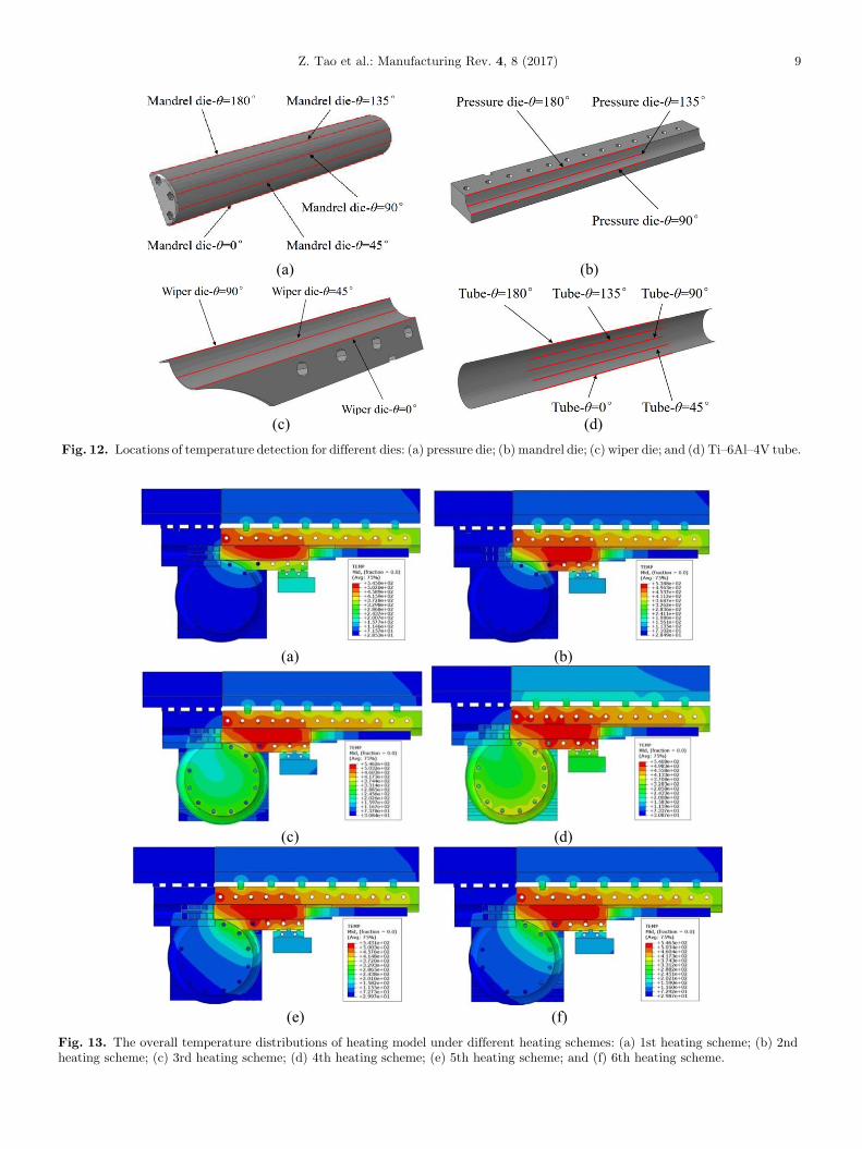
(a) (b)
(c) (d)Fig. 12. Locations of temperature detection for different dies: (a) pressure die; (b) mandrel die; (c) wiper die; and (d) Ti–6Al–4V tube.
(a) (b)
(c) (d)
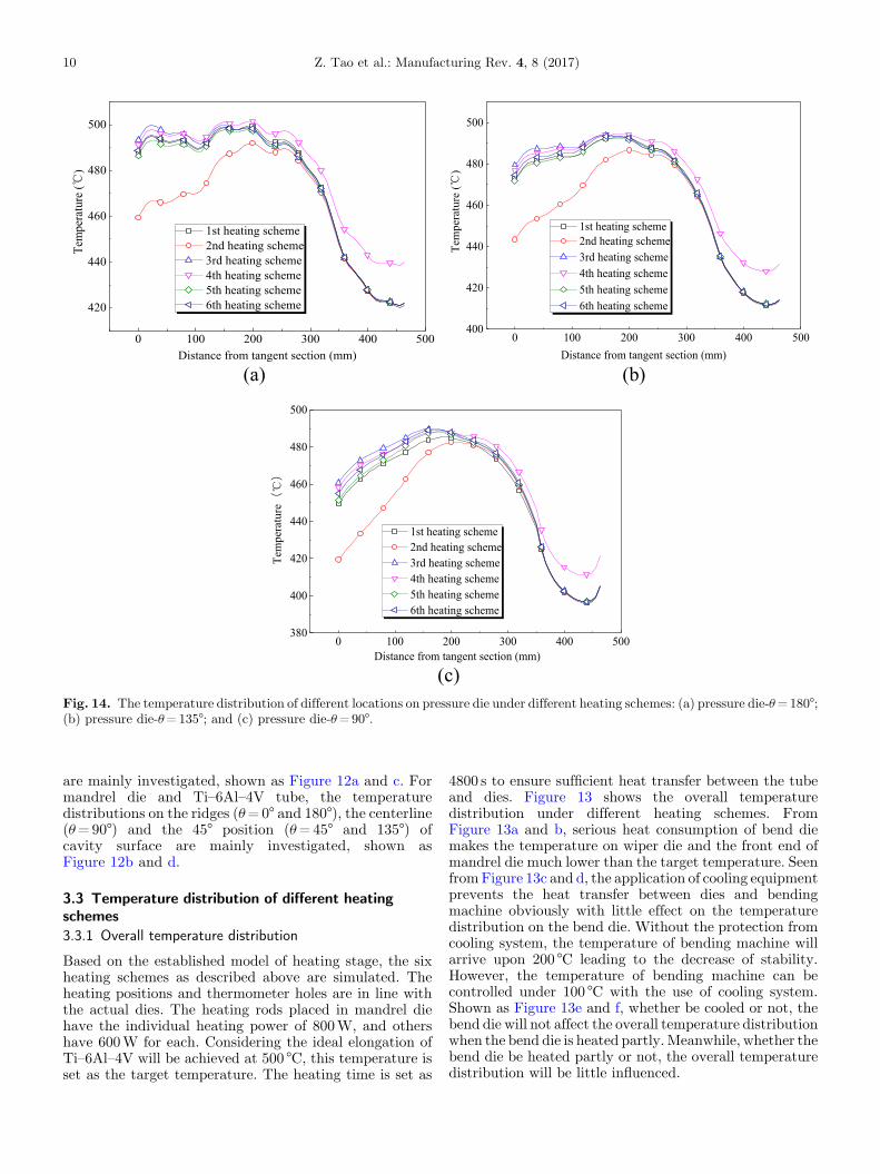
(e) (f)Fig. 13. The overall temperature distributions of heating model under different heating schemes: (a) 1st heating scheme; (b) 2ndheating scheme; (c) 3rd heating scheme; (d) 4th heating scheme; (e) 5th heating scheme; and (f) 6th heating scheme.
Z. Tao et al.: Manufacturing Rev. 4, 8 (2017) 9
0 100 200 300 400 500
420
440
460
480
500
1st heating scheme2nd heating scheme3rd heating scheme4th heating scheme5th heating scheme6th heating scheme
erutarepmeT
()
Distance from tangent section (mm)0 100 200 300 400 500
400
420
440
460
480
500
1st heating scheme 2nd heating scheme3rd heating scheme4th heating scheme5th heating scheme6th heating scheme
erutarepme T
()
Distance from tangent section (mm)
(a) (b)
0 100 200 300 400 500380
400
420
440
460
480
500
1st heating scheme2nd heating scheme3rd heating scheme4th heating scheme5th heating scheme6th heating scheme
erutarepme T
()
Distance from tangent section (mm)
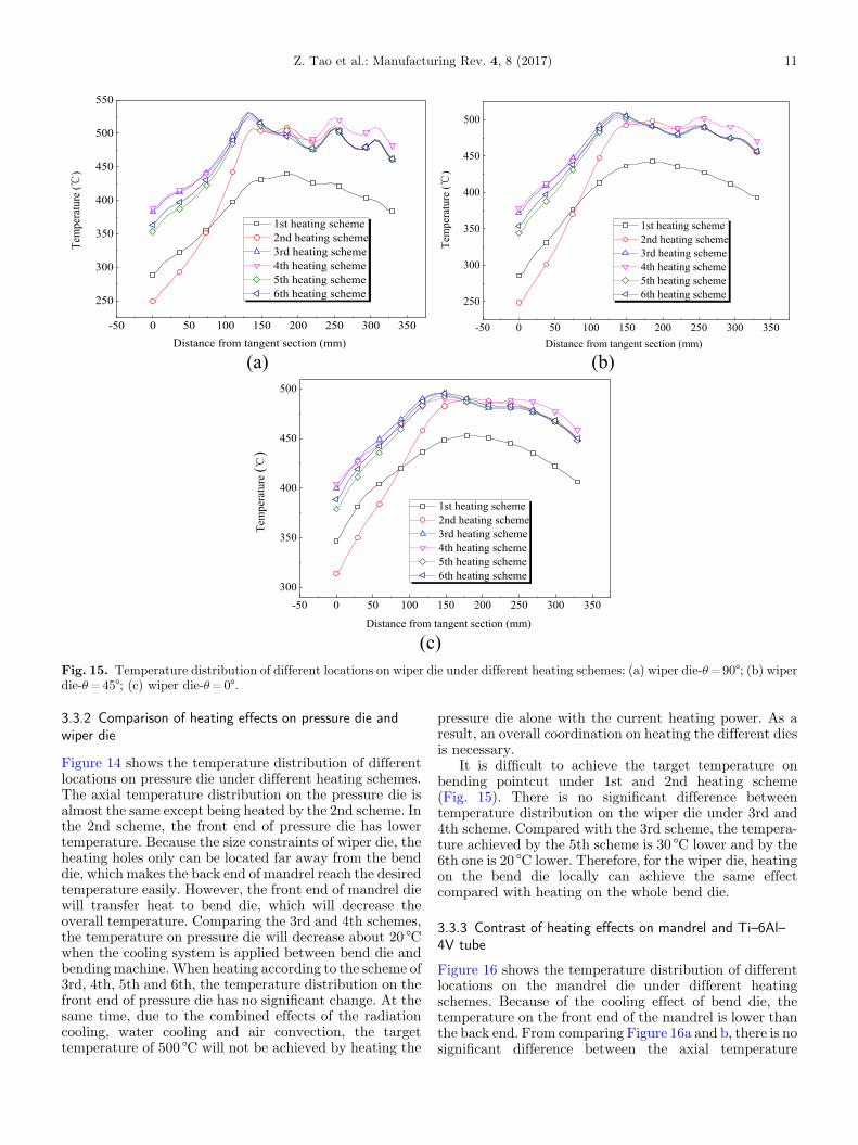
(c)Fig. 14. The temperature distribution of different locations on pressure die under different heating schemes: (a) pressure die-u=180°;(b) pressure die-u=135°; and (c) pressure die-u=90°.
10 Z. Tao et al.: Manufacturing Rev. 4, 8 (2017)
are mainly investigated, shown as Figure 12a and c. Formandrel die and Ti–6Al–4V tube, the temperaturedistributions on the ridges (u=0° and 180°), the centerline(u=90°) and the 45° position (u=45° and 135°) ofcavity surface are mainly investigated, shown asFigure 12b and d.
3.3 Temperature distribution of different heatingschemes3.3.1 Overall temperature distribution
Based on the established model of heating stage, the sixheating schemes as described above are simulated. Theheating positions and thermometer holes are in line withthe actual dies. The heating rods placed in mandrel diehave the individual heating power of 800W, and othershave 600W for each. Considering the ideal elongation ofTi–6Al–4V will be achieved at 500 °C, this temperature isset as the target temperature. The heating time is set as
4800 s to ensure sufficient heat transfer between the tubeand dies. Figure 13 shows the overall temperaturedistribution under different heating schemes. FromFigure 13a and b, serious heat consumption of bend diemakes the temperature on wiper die and the front end ofmandrel die much lower than the target temperature. SeenfromFigure 13c and d, the application of cooling equipmentprevents the heat transfer between dies and bendingmachine obviously with little effect on the temperaturedistribution on the bend die. Without the protection fromcooling system, the temperature of bending machine willarrive upon 200 °C leading to the decrease of stability.However, the temperature of bending machine can becontrolled under 100 °C with the use of cooling system.Shown as Figure 13e and f, whether be cooled or not, thebend die will not affect the overall temperature distributionwhen the bend die is heated partly.Meanwhile, whether thebend die be heated partly or not, the overall temperaturedistribution will be little influenced.
-50 0 50 100 150 200 250 300 350
250
300
350
400
450
500
550
erutarepm eT
()
Distance from tangent section (mm)
1st heating scheme2nd heating scheme3rd heating scheme4th heating scheme5th heating scheme6th heating scheme
-50 0 50 100 150 200 250 300 350
250
300
350
400
450
500
erutarepmeT
()
Distance from tangent section (mm)
1st heating scheme2nd heating scheme3rd heating scheme4th heating scheme5th heating scheme6th heating scheme
(a) (b)
-50 0 50 100 150 200 250 300 350300
350
400
450
500
Distance from tangent section (mm)
erutarepmeT
()
1st heating scheme2nd heating scheme3rd heating scheme4th heating scheme5th heating scheme6th heating scheme
(c)Fig. 15. Temperature distribution of different locations on wiper die under different heating schemes: (a) wiper die-u=90°; (b) wiperdie-u=45°; (c) wiper die-u=0°.
Z. Tao et al.: Manufacturing Rev. 4, 8 (2017) 11
3.3.2 Comparison of heating effects on pressure die andwiper die
Figure 14 shows the temperature distribution of differentlocations on pressure die under different heating schemes.The axial temperature distribution on the pressure die isalmost the same except being heated by the 2nd scheme. Inthe 2nd scheme, the front end of pressure die has lowertemperature. Because the size constraints of wiper die, theheating holes only can be located far away from the benddie, which makes the back end of mandrel reach the desiredtemperature easily. However, the front end of mandrel diewill transfer heat to bend die, which will decrease theoverall temperature. Comparing the 3rd and 4th schemes,the temperature on pressure die will decrease about 20 °Cwhen the cooling system is applied between bend die andbendingmachine.When heating according to the scheme of3rd, 4th, 5th and 6th, the temperature distribution on thefront end of pressure die has no significant change. At thesame time, due to the combined effects of the radiationcooling, water cooling and air convection, the targettemperature of 500 °C will not be achieved by heating the
pressure die alone with the current heating power. As aresult, an overall coordination on heating the different diesis necessary.
It is difficult to achieve the target temperature onbending pointcut under 1st and 2nd heating scheme(Fig. 15). There is no significant difference betweentemperature distribution on the wiper die under 3rd and4th scheme. Compared with the 3rd scheme, the tempera-ture achieved by the 5th scheme is 30 °C lower and by the6th one is 20 °C lower. Therefore, for the wiper die, heatingon the bend die locally can achieve the same effectcompared with heating on the whole bend die.
3.3.3 Contrast of heating effects on mandrel and Ti–6Al–4V tube
Figure 16 shows the temperature distribution of differentlocations on the mandrel die under different heatingschemes. Because of the cooling effect of bend die, thetemperature on the front end of the mandrel is lower thanthe back end. From comparing Figure 16a and b, there is nosignificant difference between the axial temperature
-50 0 50 100 150 200 250 300 350 400380
400
420
440
460
480
500
520
540
1st heating scheme 2nd heatingscheme3rd heating scheme4th heating scheme5th heating scheme6th heating scheme
erutarepmeT
Distance from tangent section (mm)-50 0 50 100 150 200 250 300 350 400
380
400
420
440
460
480
500
520
540
1st heating scheme2nd heating scheme3rd heating scheme4th heating scheme5th heating scheme6th heating scheme
erutarepmeT
()
Distance to tangent section (mm)
(a) (b)
-50 0 50 100 150 200 250 300 350 400340
360
380
400
420
440
460
480
500
520
540
1st heating scheme2nd heating scheme3rd heating scheme4th heating scheme5th heating scheme6th heating scheme
erutarepmeT
()
Distance from tangent section (mm)-50 0 50 100 150 200 250 300 350 400
280
320
360
400
440
480
520
560
erutarepm eT
()
Distance from tangent section (mm)
1st heating scheme2nd heating scheme3rd heating scheme4th heating scheme5th heating scheme6th heating scheme
(c) (d)
-50 0 50 100 150 200 250 300 350 400250
300
350
400
450
500
550
Distance from tangent section (mm)
erutarepme T
()
1st heating scheme2nd heating scheme3rd heating scheme4th heating scheme5th heating scheme6th heating scheme
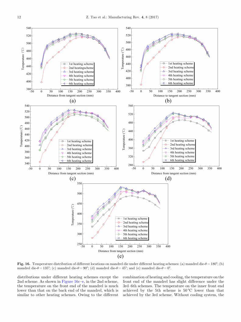
(e)Fig. 16. Temperature distribution of different locations on mandrel die under different heating schemes: (a) mandrel die-u=180°; (b)mandrel die-u=135°; (c) mandrel die-u=90°; (d) mandrel die-u=45°; and (e) mandrel die-u=0°.
12 Z. Tao et al.: Manufacturing Rev. 4, 8 (2017)
distributions under different heating schemes except the2nd scheme. As shown in Figure 16c–e, in the 2nd scheme,the temperature on the front end of the mandrel is muchlower than that on the back end of the mandrel, which issimilar to other heating schemes. Owing to the different
combination of heating and cooling, the temperature on thefront end of the mandrel has slight difference under the3rd–6th schemes. The temperature on the inner front endachieved by the 5th scheme is 50 °C lower than thatachieved by the 3rd scheme. Without cooling system, the
-50 0 50 100 150 200 250 300 350 400420
440
460
480
500
520
Distance to tangent section (mm)
erutarepmeT
()
1st heating scheme2nd heating scheme3rd heating scheme4th heating scheme5th heating scheme6th heating scheme
-50 0 50 100 150 200 250 300 350 400420
440
460
480
500
520
Distance from tangent section (mm)
erutarepmeT
()
1st heating scheme2nd heating scheme3rd heating scheme4th heating scheme5th heating scheme6th heating scheme
(a) (b)
-50 0 50 100 150 200 250 300 350 400380
400
420
440
460
480
500
520
erutarepmeT
()
Distance from tangent section (mm)
1st heatingscheme2nd heating scheme3rd heating scheme4th heating scheme5th heating scheme6th heating scheme
-50 0 50 100 150 200 250 300 350 400
250
300
350
400
450
500
550
Distance from tangent section (mm)
erutarepmeT
(�)
1st heating scheme2nd heating scheme3rd heating scheme4th heating scheme5th heating scheme6th heating scheme
(c) (d)
-50 0 50 100 150 200 250 300 350 400
250
300
350
400
450
500
550
Distance from tangent section (mm)
erutarepmeT
( �)
1st heating scheme2nd heating scheme3rd heating scheme4th heating scheme5th heating scheme6th heating scheme
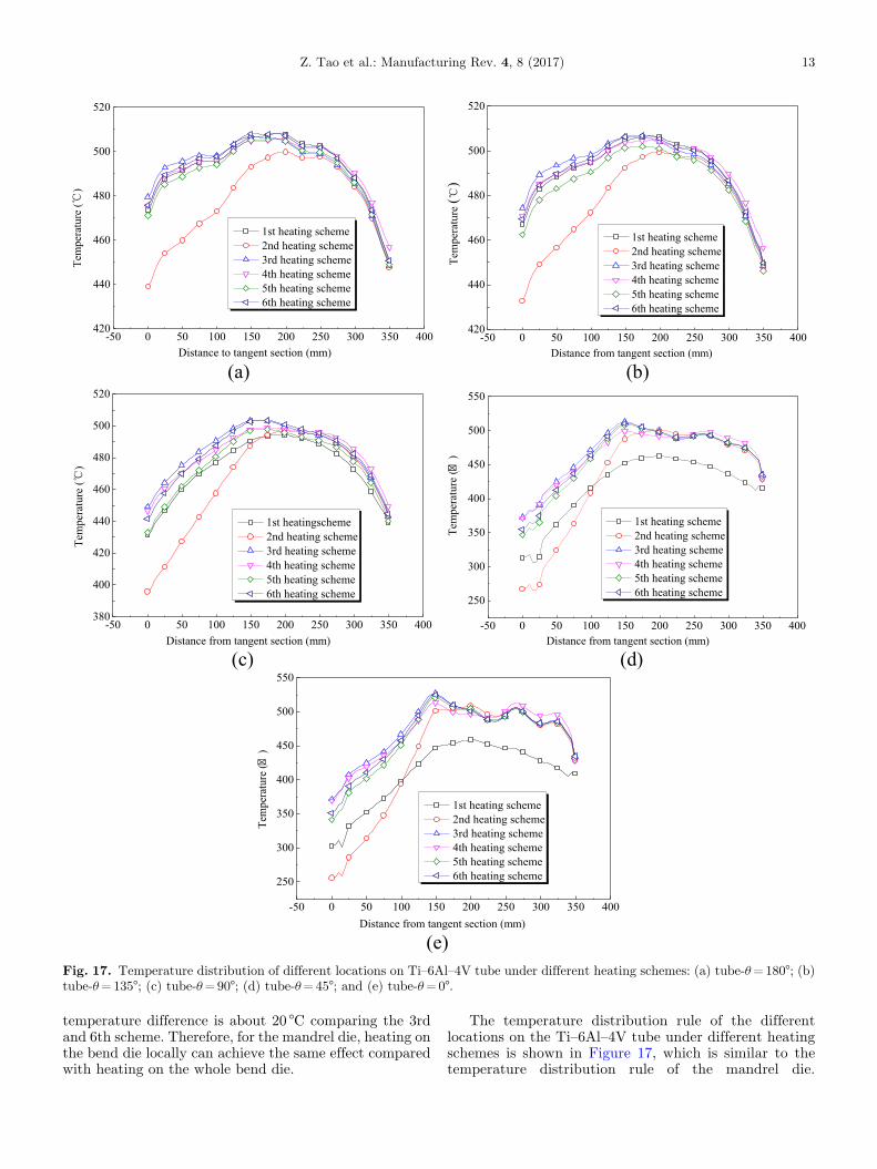
(e)Fig. 17. Temperature distribution of different locations on Ti–6Al–4V tube under different heating schemes: (a) tube-u=180°; (b)tube-u=135°; (c) tube-u=90°; (d) tube-u=45°; and (e) tube-u=0°.
Z. Tao et al.: Manufacturing Rev. 4, 8 (2017) 13
temperature difference is about 20 °C comparing the 3rdand 6th scheme. Therefore, for the mandrel die, heating onthe bend die locally can achieve the same effect comparedwith heating on the whole bend die.
The temperature distribution rule of the differentlocations on the Ti–6Al–4V tube under different heatingschemes is shown in Figure 17, which is similar to thetemperature distribution rule of the mandrel die.
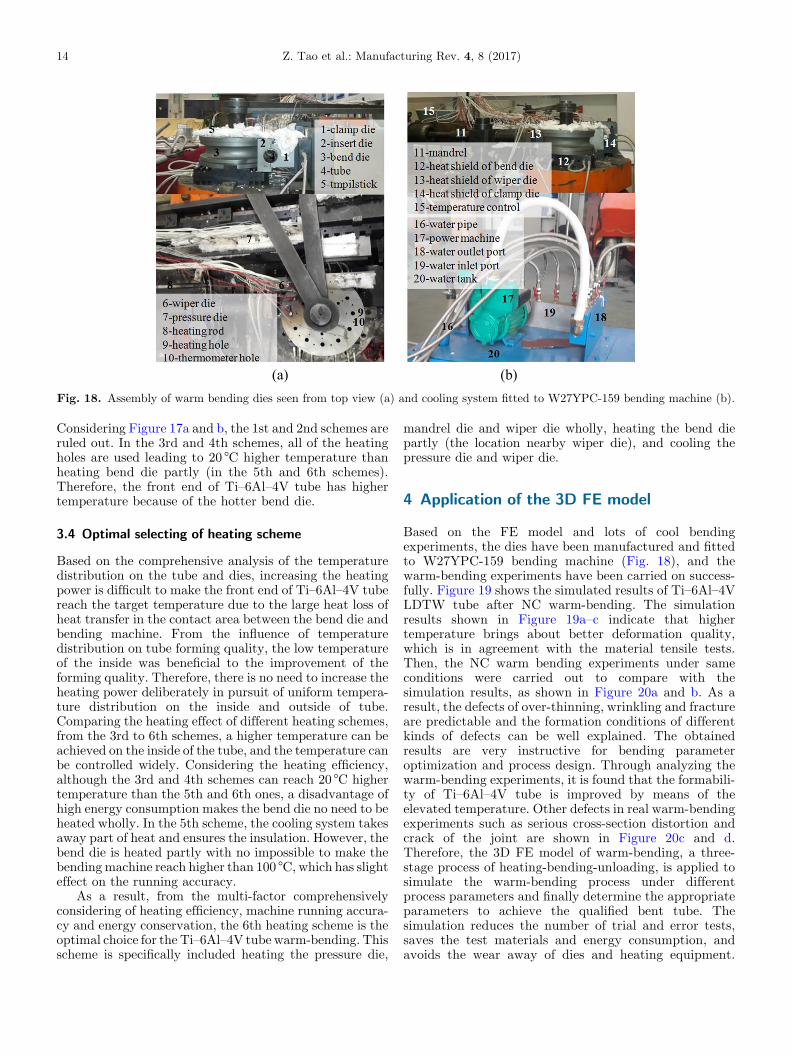
(a) (b)Fig. 18. Assembly of warm bending dies seen from top view (a) and cooling system fitted to W27YPC-159 bending machine (b).
14 Z. Tao et al.: Manufacturing Rev. 4, 8 (2017)
Considering Figure 17a and b, the 1st and 2nd schemes areruled out. In the 3rd and 4th schemes, all of the heatingholes are used leading to 20 °C higher temperature thanheating bend die partly (in the 5th and 6th schemes).Therefore, the front end of Ti–6Al–4V tube has highertemperature because of the hotter bend die.
3.4 Optimal selecting of heating scheme
Based on the comprehensive analysis of the temperaturedistribution on the tube and dies, increasing the heatingpower is difficult to make the front end of Ti–6Al–4V tubereach the target temperature due to the large heat loss ofheat transfer in the contact area between the bend die andbending machine. From the influence of temperaturedistribution on tube forming quality, the low temperatureof the inside was beneficial to the improvement of theforming quality. Therefore, there is no need to increase theheating power deliberately in pursuit of uniform tempera-ture distribution on the inside and outside of tube.Comparing the heating effect of different heating schemes,from the 3rd to 6th schemes, a higher temperature can beachieved on the inside of the tube, and the temperature canbe controlled widely. Considering the heating efficiency,although the 3rd and 4th schemes can reach 20 °C highertemperature than the 5th and 6th ones, a disadvantage ofhigh energy consumption makes the bend die no need to beheated wholly. In the 5th scheme, the cooling system takesaway part of heat and ensures the insulation. However, thebend die is heated partly with no impossible to make thebendingmachine reach higher than 100 °C, which has slighteffect on the running accuracy.
As a result, from the multi-factor comprehensivelyconsidering of heating efficiency, machine running accura-cy and energy conservation, the 6th heating scheme is theoptimal choice for the Ti–6Al–4V tube warm-bending. Thisscheme is specifically included heating the pressure die,
mandrel die and wiper die wholly, heating the bend diepartly (the location nearby wiper die), and cooling thepressure die and wiper die.
4 Application of the 3D FE model
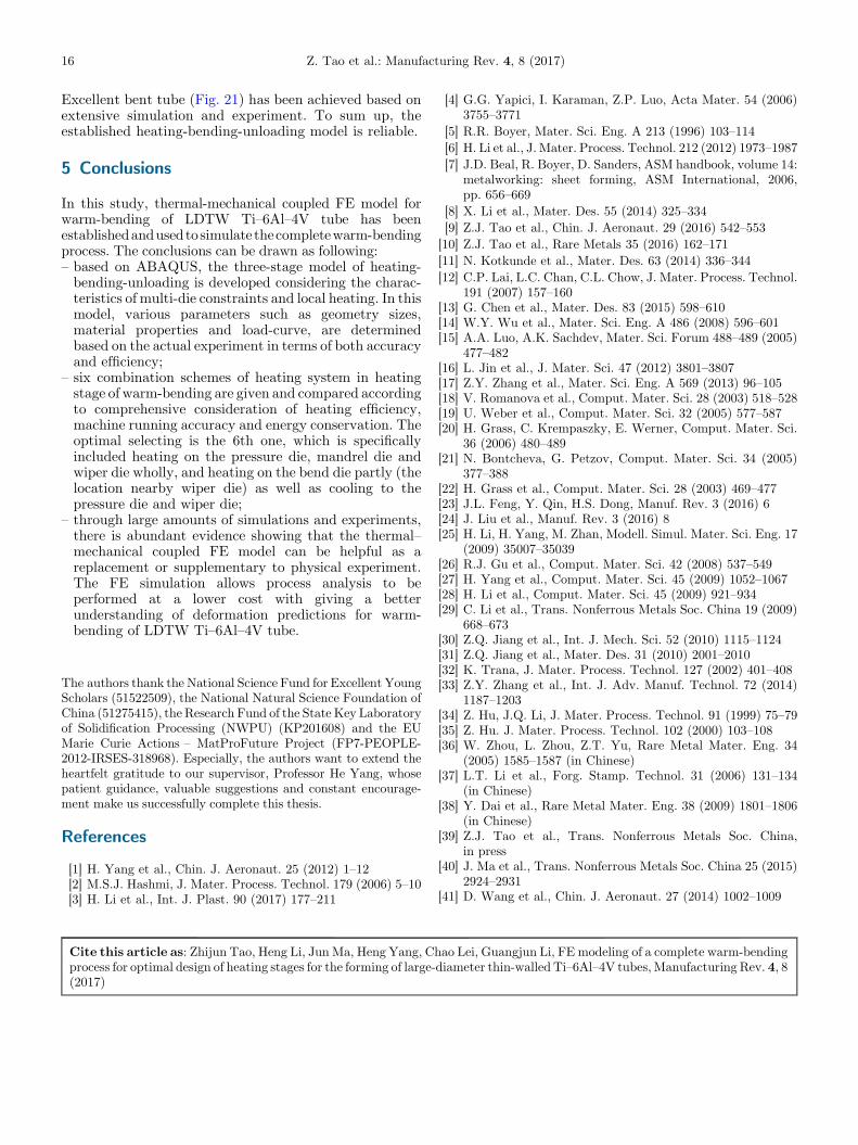
Based on the FE model and lots of cool bendingexperiments, the dies have been manufactured and fittedto W27YPC-159 bending machine (Fig. 18), and thewarm-bending experiments have been carried on success-fully. Figure 19 shows the simulated results of Ti–6Al–4VLDTW tube after NC warm-bending. The simulationresults shown in Figure 19a–c indicate that highertemperature brings about better deformation quality,which is in agreement with the material tensile tests.Then, the NC warm bending experiments under sameconditions were carried out to compare with thesimulation results, as shown in Figure 20a and b. As aresult, the defects of over-thinning, wrinkling and fractureare predictable and the formation conditions of differentkinds of defects can be well explained. The obtainedresults are very instructive for bending parameteroptimization and process design. Through analyzing thewarm-bending experiments, it is found that the formabili-ty of Ti–6Al–4V tube is improved by means of theelevated temperature. Other defects in real warm-bendingexperiments such as serious cross-section distortion andcrack of the joint are shown in Figure 20c and d.Therefore, the 3D FE model of warm-bending, a three-stage process of heating-bending-unloading, is applied tosimulate the warm-bending process under differentprocess parameters and finally determine the appropriateparameters to achieve the qualified bent tube. Thesimulation reduces the number of trial and error tests,saves the test materials and energy consumption, andavoids the wear away of dies and heating equipment.
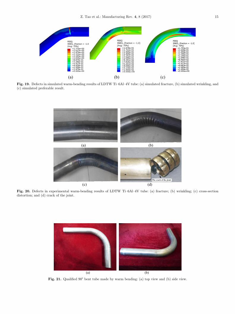
(a) (b) (c) Fig. 19. Defects in simulated warm-bending results of LDTW Ti–6Al–4V tube: (a) simulated fracture, (b) simulated wrinkling, and(c) simulated preferable result.
(a) (b)
(c) (d)
Fig. 20. Defects in experimental warm-bending results of LDTW Ti–6Al–4V tube: (a) fracture; (b) wrinkling; (c) cross-sectiondistortion; and (d) crack of the joint.
(a) (b)
Fig. 21. Qualified 90° bent tube made by warm bending: (a) top view and (b) side view.
Z. Tao et al.: Manufacturing Rev. 4, 8 (2017) 15
16 Z. Tao et al.: Manufacturing Rev. 4, 8 (2017)
Excellent bent tube (Fig. 21) has been achieved based onextensive simulation and experiment. To sum up, theestablished heating-bending-unloading model is reliable.
5 Conclusions
In this study, thermal-mechanical coupled FE model forwarm-bending of LDTW Ti–6Al–4V tube has beenestablishedandusedtosimulate thecompletewarm-bendingprocess. The conclusions can be drawn as following:
– based on ABAQUS, the three-stage model of heating-bending-unloading is developed considering the charac-teristics of multi-die constraints and local heating. In thismodel, various parameters such as geometry sizes,material properties and load-curve, are determinedbased on the actual experiment in terms of both accuracyand efficiency;–
six combination schemes of heating system in heatingstage of warm-bending are given and compared accordingto comprehensive consideration of heating efficiency,machine running accuracy and energy conservation. Theoptimal selecting is the 6th one, which is specificallyincluded heating on the pressure die, mandrel die andwiper die wholly, and heating on the bend die partly (thelocation nearby wiper die) as well as cooling to thepressure die and wiper die;–
through large amounts of simulations and experiments,there is abundant evidence showing that the thermal–mechanical coupled FE model can be helpful as areplacement or supplementary to physical experiment.The FE simulation allows process analysis to beperformed at a lower cost with giving a betterunderstanding of deformation predictions for warm-bending of LDTW Ti–6Al–4V tube.The authors thank the National Science Fund for Excellent YoungScholars (51522509), the National Natural Science Foundation ofChina (51275415), the Research Fund of the State Key Laboratoryof Solidification Processing (NWPU) (KP201608) and the EUMarie Curie Actions – MatProFuture Project (FP7-PEOPLE-2012-IRSES-318968). Especially, the authors want to extend theheartfelt gratitude to our supervisor, Professor He Yang, whosepatient guidance, valuable suggestions and constant encourage-ment make us successfully complete this thesis.
References
[1] H. Yang et al., Chin. J. Aeronaut. 25 (2012) 1–12[2] M.S.J. Hashmi, J. Mater. Process. Technol. 179 (2006) 5–10[3] H. Li et al., Int. J. Plast. 90 (2017) 177–211
[4] G.G. Yapici, I. Karaman, Z.P. Luo, Acta Mater. 54 (2006)3755–3771
[5] R.R. Boyer, Mater. Sci. Eng. A 213 (1996) 103–114[6] H. Li et al., J. Mater. Process. Technol. 212 (2012) 1973–1987[7] J.D. Beal, R. Boyer, D. Sanders, ASM handbook, volume 14:
metalworking: sheet forming, ASM International, 2006,pp. 656–669
[8] X. Li et al., Mater. Des. 55 (2014) 325–334[9] Z.J. Tao et al., Chin. J. Aeronaut. 29 (2016) 542–553[10] Z.J. Tao et al., Rare Metals 35 (2016) 162–171[11] N. Kotkunde et al., Mater. Des. 63 (2014) 336–344[12] C.P. Lai, L.C. Chan, C.L. Chow, J. Mater. Process. Technol.
191 (2007) 157–160[13] G. Chen et al., Mater. Des. 83 (2015) 598–610[14] W.Y. Wu et al., Mater. Sci. Eng. A 486 (2008) 596–601[15] A.A. Luo, A.K. Sachdev, Mater. Sci. Forum 488–489 (2005)
477–482[16] L. Jin et al., J. Mater. Sci. 47 (2012) 3801–3807[17] Z.Y. Zhang et al., Mater. Sci. Eng. A 569 (2013) 96–105[18] V. Romanova et al., Comput. Mater. Sci. 28 (2003) 518–528[19] U. Weber et al., Comput. Mater. Sci. 32 (2005) 577–587[20] H. Grass, C. Krempaszky, E. Werner, Comput. Mater. Sci.
36 (2006) 480–489[21] N. Bontcheva, G. Petzov, Comput. Mater. Sci. 34 (2005)
377–388[22] H. Grass et al., Comput. Mater. Sci. 28 (2003) 469–477[23] J.L. Feng, Y. Qin, H.S. Dong, Manuf. Rev. 3 (2016) 6[24] J. Liu et al., Manuf. Rev. 3 (2016) 8[25] H. Li, H. Yang, M. Zhan, Modell. Simul. Mater. Sci. Eng. 17
(2009) 35007–35039[26] R.J. Gu et al., Comput. Mater. Sci. 42 (2008) 537–549[27] H. Yang et al., Comput. Mater. Sci. 45 (2009) 1052–1067[28] H. Li et al., Comput. Mater. Sci. 45 (2009) 921–934[29] C. Li et al., Trans. Nonferrous Metals Soc. China 19 (2009)
668–673[30] Z.Q. Jiang et al., Int. J. Mech. Sci. 52 (2010) 1115–1124[31] Z.Q. Jiang et al., Mater. Des. 31 (2010) 2001–2010[32] K. Trana, J. Mater. Process. Technol. 127 (2002) 401–408[33] Z.Y. Zhang et al., Int. J. Adv. Manuf. Technol. 72 (2014)
1187–1203[34] Z. Hu, J.Q. Li, J. Mater. Process. Technol. 91 (1999) 75–79[35] Z. Hu. J. Mater. Process. Technol. 102 (2000) 103–108[36] W. Zhou, L. Zhou, Z.T. Yu, Rare Metal Mater. Eng. 34
(2005) 1585–1587 (in Chinese)[37] L.T. Li et al., Forg. Stamp. Technol. 31 (2006) 131–134
(in Chinese)[38] Y. Dai et al., Rare Metal Mater. Eng. 38 (2009) 1801–1806
(in Chinese)[39] Z.J. Tao et al., Trans. Nonferrous Metals Soc. China,
in press[40] J. Ma et al., Trans. Nonferrous Metals Soc. China 25 (2015)
2924–2931[41] D. Wang et al., Chin. J. Aeronaut. 27 (2014) 1002–1009
Cite this article as: Zhijun Tao, Heng Li, Jun Ma, Heng Yang, Chao Lei, Guangjun Li, FE modeling of a complete warm-bendingprocess for optimal design of heating stages for the forming of large-diameter thin-walled Ti–6Al–4V tubes,Manufacturing Rev. 4, 8(2017)