Embed Size (px)
Citation preview
Guardian Avionics LLC Document No. 100-M 1951 E. AIRPORT DRIVE Date: 03/28/18 TUCSON, AZ. 85706 REV: B
Page 1 of 13
Installation Manual/Instructions
IFDR Panel Mounts/USB/Cooling Fan
Guardian Avionics LLC Document No. 100-M 1951 E. AIRPORT DRIVE Date: 03/28/18 TUCSON, AZ. 85706 REV: B
Page 2 of 13
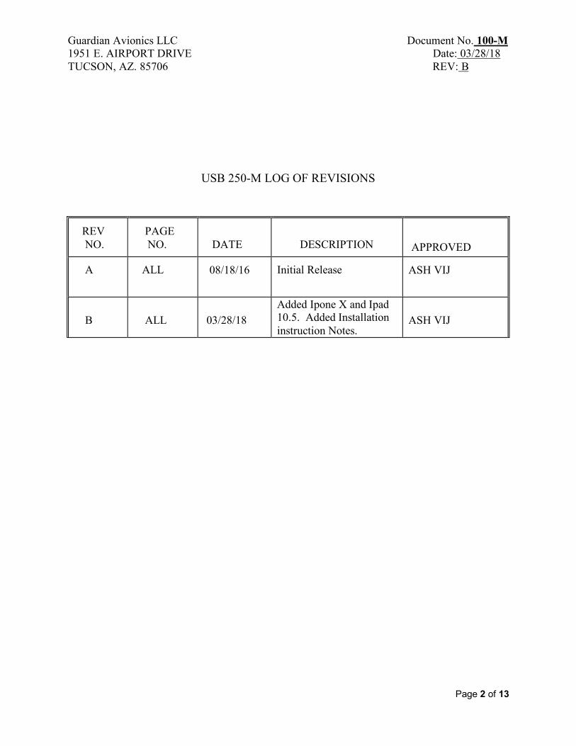
USB 250-M LOG OF REVISIONS REV NO.
PAGE NO.
DATE
DESCRIPTION
APPROVED
A
ALL
08/18/16
Initial Release
ASH VIJ
B
ALL
03/28/18
Added Ipone X and Ipad 10.5. Added Installation instruction Notes.
ASH VIJ
Guardian Avionics LLC Document No. 100-M 1951 E. AIRPORT DRIVE Date: 03/28/18 TUCSON, AZ. 85706 REV: B
Page 3 of 13
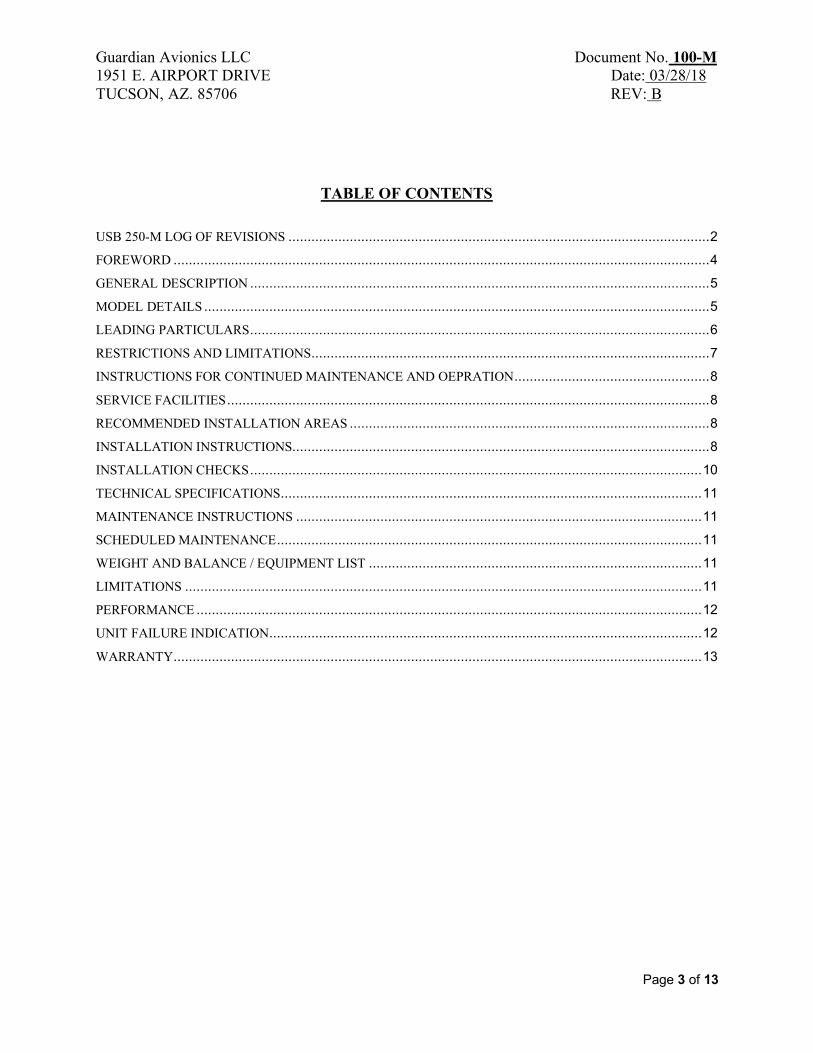
TABLE OF CONTENTS
USB 250-M LOG OF REVISIONS .............................................................................................................. 2
FOREWORD ............................................................................................................................................ 4
GENERAL DESCRIPTION ........................................................................................................................ 5
MODEL DETAILS .................................................................................................................................... 5
LEADING PARTICULARS ........................................................................................................................ 6
RESTRICTIONS AND LIMITATIONS ........................................................................................................ 7
INSTRUCTIONS FOR CONTINUED MAINTENANCE AND OEPRATION ................................................... 8
SERVICE FACILITIES .............................................................................................................................. 8
RECOMMENDED INSTALLATION AREAS .............................................................................................. 8
INSTALLATION INSTRUCTIONS ............................................................................................................. 8
INSTALLATION CHECKS ...................................................................................................................... 10
TECHNICAL SPECIFICATIONS .............................................................................................................. 11
MAINTENANCE INSTRUCTIONS .......................................................................................................... 11
SCHEDULED MAINTENANCE ............................................................................................................... 11
WEIGHT AND BALANCE / EQUIPMENT LIST ....................................................................................... 11
LIMITATIONS ....................................................................................................................................... 11
PERFORMANCE .................................................................................................................................... 12
UNIT FAILURE INDICATION ................................................................................................................. 12
WARRANTY .......................................................................................................................................... 13
Guardian Avionics LLC Document No. 100-M 1951 E. AIRPORT DRIVE Date: 03/28/18 TUCSON, AZ. 85706 REV: B
Page 4 of 13
FOREWORD This document provides information intended for use by persons who, pursuant to current requirements, are qualified to install this equipment. Because equipment and system installations vary depending on a particular aircraft, this document is intended only as a guideline. If further information is required, contact:
Guardian Avionics, LLC 1951 E. Airport Drive
Tucson, AZ 85706 (520) 889-1177 (800) 639-7139
www.guardianavionics.com We welcome your comments concerning this document. Although every effort has been made to keep it free of errors, some may occur. When reporting a specific problem, please describe it briefly and include the document number, the paragraph/figure/picture/table number, and the page number. Send your comments to the address above.

Guardian Avionics LLC Document No. 100-M 1951 E. AIRPORT DRIVE Date: 03/28/18 TUCSON, AZ. 85706 REV: B
Page 5 of 13
GENERAL DESCRIPTION
The iFDR Panel Mount series is a new flush mounting system to easily dock and seamlessly integrate your Apple family of products (6, 6+ X, Ipad mini, Air/pro 9.7/10.5 and 12.9 Pro) into your aircraft instrument panel – giving it a clean, professional appearance in an easy to view position! Once installed, the iFDR mount allows your iPhone to be docked in seconds, fully connected to power and audio with built-in cable ports. Removal is just as easy – just slide, push, and remove! The iFDR Panel Mount was designed by aerospace engineers to perform in the unique environment of the cockpit. The spring actuated mounting cradle securely holds the iPad or iPhone in place during the roughest of turbulence. The clean, flush mount has a shallow chassis allowing it to be easily installed in even the smallest of instrument panels. Built-in ports for the Apple Lightning plug and a 3.5mm audio cable help keep cables safely and securely positioned behind the panel, allowing you the ability to connect to power, data, and audio without the cord mess. The equipment is approved for VFR use only. USB charging consists of Dual USB charging that can supply up to 3.0 Amps in USB A and USB C per USB Org specs. The Cooling Fan is designed to have approximately 4.6 CFM of air flow as an option to keep the Ipad/Iphone Cooled.
MODEL DETAILS
The iFDR panel mount comes in five different models to accommodate specific iPhone / iPad models. These are as illustrated below –
iPhone 6 and X Mount iPhone 6+ Mount iPad Mini Mount
iPad Air / Pro 9.7 and 10.5” Mount iPad Pro 12.9” Mount
Guardian Avionics LLC Document No. 100-M 1951 E. AIRPORT DRIVE Date: 03/28/18 TUCSON, AZ. 85706 REV: B
Page 6 of 13
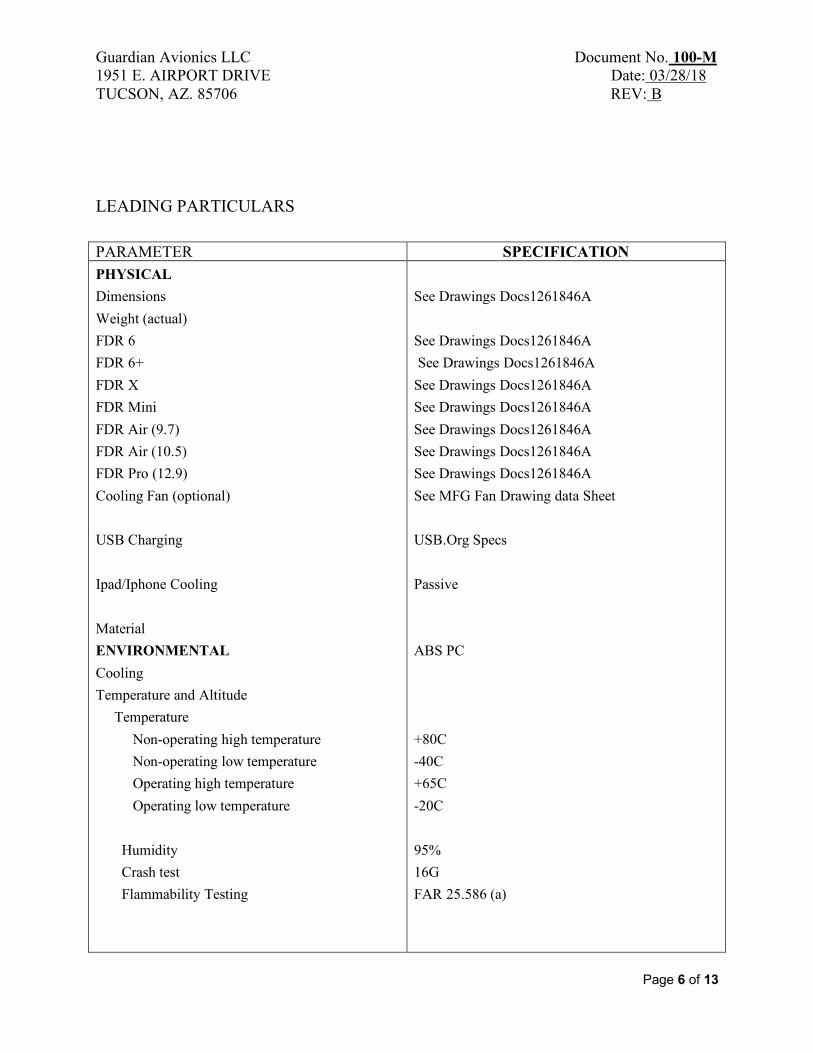
LEADING PARTICULARS PARAMETER SPECIFICATION PHYSICAL Dimensions Weight (actual) FDR 6 FDR 6+ FDR X FDR Mini FDR Air (9.7) FDR Air (10.5) FDR Pro (12.9) Cooling Fan (optional) USB Charging Ipad/Iphone Cooling Material ENVIRONMENTAL Cooling Temperature and Altitude Temperature Non-operating high temperature Non-operating low temperature Operating high temperature Operating low temperature Humidity Crash test Flammability Testing
See Drawings Docs1261846A See Drawings Docs1261846A See Drawings Docs1261846A See Drawings Docs1261846A See Drawings Docs1261846A See Drawings Docs1261846A See Drawings Docs1261846A See Drawings Docs1261846A See MFG Fan Drawing data Sheet USB.Org Specs Passive ABS PC +80C -40C +65C -20C 95% 16G FAR 25.586 (a)
Guardian Avionics LLC Document No. 100-M 1951 E. AIRPORT DRIVE Date: 03/28/18 TUCSON, AZ. 85706 REV: B
Page 7 of 13
RESTRICTIONS AND LIMITATIONS
This unit is approved under the FAA modifications to improve safety; the relevant approval for all such equipment is explained here and on our website. This product is manufactured under 21.8(d) for equipment designated as to be Minor change per the FAA to type design and whose failure condition is minor. Note: “NORSEE approval does not specifically authorize installation on an aircraft. It is the responsibility of the installer to determine if the installation of this NORSEE device meets the requirements of a minor alteration. Further FAA installation approval will be required for installations not meeting the definition of a minor alteration. In all cases, the installer must properly document the installation in the aircraft maintenance records”
Guardian Avionics has determined that the installation of iFDR dock mounts is minor per 14 CFR Part 21.93 as it has no appreciable effect on the weight, balance, structural strength, reliability, operation characteristics or other characteristics affecting the airworthiness of the aircraft it is installed in. Note: It’s recommended that the Installer shall consider his installation on an induvial basis as panel structural integrity varies with each aircraft panel model and existing equipment previously installed. It’s up to the Installer to determine if this is a minor.
Installation of the iFDR dock mount Series is supplemental only; it is not intended as a replacement for or modification to an existing, approved or required system. Installation in a commuter or transport category airplane is prohibited, unless approved by the FAA or local FISDO.
The iFDR mount system may not be used as a substitution for the certificated aircraft systems. No operational credit may be taken for installation of the system.
Guardian Avionics LLC Document No. 100-M 1951 E. AIRPORT DRIVE Date: 03/28/18 TUCSON, AZ. 85706 REV: B
Page 8 of 13
INSTRUCTIONS FOR CONTINUED MAINTENANCE AND OEPRATION
iFDR Mounts are on condition parts. No maintenance is required. If the unit fails to operate as intended, please contact Guardian Avionics.
SERVICE FACILITIES
The operator can service all other components of the installation at an FAA certified Repair Station or by A&P mechanic.
RECOMMENDED INSTALLATION AREAS
FDR Mounting System can be installed in the aircraft cabin area. Use Guardian Avionics drawing “Docks12617846A Rev B” or later as a reference.
INSTALLATION INSTRUCTIONS
Note: FDR Mounts/power Supplies/Cooling Fans are not a required equipment and nay not be used as substitution for the certificated aircraft system. No Operational credit may be taken for installation of FDR Mounts/Power Supplies/Cooling Fans.
Note: “NORSEE approval does not specifically authorize installation on an aircraft. It is the responsibility of the installer to determine if the installation of this NORSEE device meets the requirements of a minor alteration. Further FAA installation approval will be required for installations not meeting the definition of a minor alteration. In all cases, the installer must properly document the installation in the aircraft maintenance records”
The latest installation drawings will be available at this link to the Company website (FDR 100 Rev. A or later and USB 100 Rev A. These can be referred to in case of a doubt. The installation kit will consist of the following optional power supply FDR 150/250- 301.
• Mount and Power Package for the Mount, Power Supply, Lightning Cable,
Audio Cable
Guardian Avionics LLC Document No. 100-M 1951 E. AIRPORT DRIVE Date: 03/28/18 TUCSON, AZ. 85706 REV: B
Page 9 of 13
The kit can also be procured in parts with the mount and other components being procured separately.
The following documents the installation criteria for all series of mounts. Detailed drawings for each mount are available in the Appendix of this manual
(a) Choose a location in the instrument panel for the installation of the mount with space available (see drawing “Docks12617846A Rev B or later) for cutout requirements).
(b) Install the mount per the Installation Manual “Docks12617846A Rev. B or Later).
If USB power (5V) is installed using Guardian Avionics Mounts 150/250-301 (drawing USB-250 Rev. E or later)
(c) Install the FAA Approved USB circuit breaker (2 AMP) on the non-essential power buss if optional installed. An optional Inline (2 AMP) fuse can be used as an alternate to the Circuit Breaker. This will ensure that in the event of a generator failure, USB charging will cut off to minimize load on the aircraft battery.
(d) Connect the power line to the +14V or +28V DC power output as applicable
(e) If a jumper wire is required to connect the USB charger to the CB, use 20 Gauge MIL-W-22759/16 or equivalent wire. Wiring is to be performed in accordance with AC 43.13-1B, 2A, acceptable methods, techniques and practices.
(f) Create a mounting hole in the selected location of a size as indicated in Appendix and mount the device.
(g) Install Mounts per drawing hardware
Cooling Fan Installation
(h) Installation of the cooling fan per Guardian Avionics drawing USB-250 Rev. E or later.
Note: FDR Mounts/USB power Supplies/Cooling Supply are not a required equipment and nay not be used as substitution for the certificated aircraft system.
Note: “NORSEE approval does not specifically authorize installation on an aircraft. It is the responsibility of the installer to determine if the installation of this NORSEE device meets the requirements of a minor alteration. Further FAA installation approval will be required for installations not meeting the definition
Guardian Avionics LLC Document No. 100-M 1951 E. AIRPORT DRIVE Date: 03/28/18 TUCSON, AZ. 85706 REV: B
Page 10 of 13
of a minor alteration. In all cases, the installer must properly document the installation in the aircraft maintenance records”
INSTALLATION CHECKS
(a) Verify the Apple device (iphone/ipad) can be easily installed and removed. The installation is no way effecting or interfering with the pilot or co pilot normal flight operation.
Optional power Installation Check
(b) With the With the USB charger disconnected from the aircraft harness, carry out a continuity check of the added wiring.
(c) USB charger disconnected from the aircraft harness, carry out a continuity check of the added wiring.
(d) Connect the USB charger connector to the aircraft harness. Turn aircraft Battery Switch ON. Close USB circuit breaker. Slide the iPad / iPhone into the mount. Check for firm mounting and correct connection of Lightning and audio cables.
(e) Check the USB charger for correct operation. Verify the charger can be shut off with the USB circuit breaker
(f) Verify there no EMI interference is observed will to all cockpit equipment once the fan is installed and is turned on and off is observed.
(g) It’s also recommended that a test flight be accomplished with the Circuit breaker turned on and off to verify no EMI interference with the cockpit instruments is overserved.
Optional Cooling Fan Installation Check
(h) Verify that the fan has enough clearances in the back and is separated from other equipment. Verify it also has proper ventilation.
(i) Verify there no EMI interference is observed will to all cockpit equipment once the fan is installed and is turned on and off is observed.
(j) It’s also recommended that a test flight be accomplished with the Circuit breaker turned on and off to verify no EMI interference with the cockpit instruments is overserved.
Guardian Avionics LLC Document No. 100-M 1951 E. AIRPORT DRIVE Date: 03/28/18 TUCSON, AZ. 85706 REV: B
Page 11 of 13
TECHNICAL SPECIFICATIONS
See page 6 “Leading Particulars”
MAINTENANCE INSTRUCTIONS The iFDR Mounts/USB Power supplies/Cooling Fans do not require periodic scheduled servicing or periodic scheduled preventive maintenance.
The iFDR series Mounts/USB Power Supplies/Cooling Fans must be returned to Guardian Avionics LLC for any servicing or repairs that may be required. The aircraft wiring harness, circuit breaker shall be included in the maintenance instructions for general visual inspections for system integrity, installation security, corrosion and chaffing.
SCHEDULED MAINTENANCE
On Condition, No Scheduled maintenance is required.
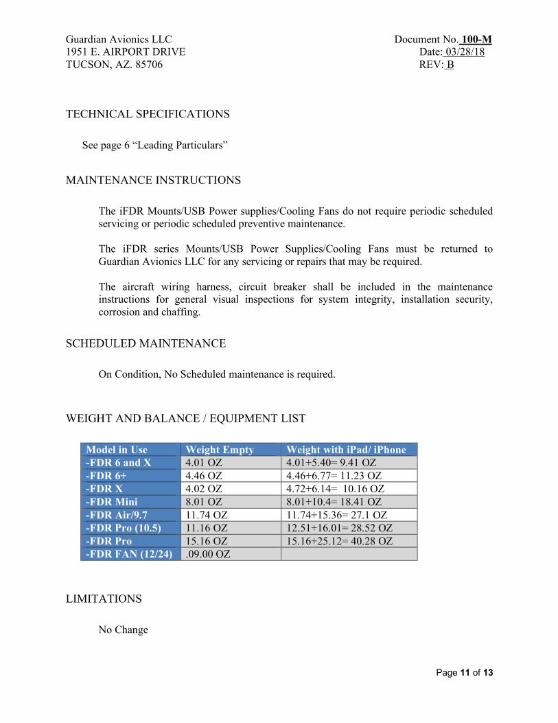
WEIGHT AND BALANCE / EQUIPMENT LIST
Model in Use Weight Empty Weight with iPad/ iPhone -FDR 6 and X 4.01 OZ 4.01+5.40= 9.41 OZ -FDR 6+ 4.46 OZ 4.46+6.77= 11.23 OZ -FDR X 4.02 OZ 4.72+6.14= 10.16 OZ -FDR Mini 8.01 OZ 8.01+10.4= 18.41 OZ -FDR Air/9.7 11.74 OZ 11.74+15.36= 27.1 OZ -FDR Pro (10.5) 11.16 OZ 12.51+16.01= 28.52 OZ -FDR Pro 15.16 OZ 15.16+25.12= 40.28 OZ -FDR FAN (12/24) .09.00 OZ
LIMITATIONS
No Change
Guardian Avionics LLC Document No. 100-M 1951 E. AIRPORT DRIVE Date: 03/28/18 TUCSON, AZ. 85706 REV: B
Page 12 of 13
PERFORMANCE
No Change
UNIT FAILURE INDICATION
Two types of failure are possible
(a) The mount does not hold the device correctly (b) The Lightning or the Audio connectors do not engage correctly with the
mounts. (c) USB not Charging and Internal green light is not turning on or showing red (d) Cooling Fan not turning on or is making a noise
In all cases, the unit should be returned to Guardian Avionics for repair.
Guardian Avionics LLC Document No. 100-M 1951 E. AIRPORT DRIVE Date: 03/28/18 TUCSON, AZ. 85706 REV: B
Page 13 of 13
WARRANTY WARRANTY COVERAGE: CO GUARDIAN LLC. WARRANTS TO THE ORIGINAL CONSUMER PURCHASER, THAT THIS EQUIPMENT WILL BE FREE OF DEFECTS IN MATERIAL AND WORKMANSHIP FOR A PERIOD OF ONE (1) YEAR FROM DATE OF PURCHASE. THE MANUFACTURER'S LIABILITY HEREUNDER IS LIMITED TO REPLACEMENT OF THE PRODUCT, REPAIR OF THE PRODUCT OR REPLACEMENT OF THE PRODUCT WITH A REPAIRED PRODUCT AT THE DISCRETION OF THE MANUFACTURER. THIS WARRANTY IS VOID IF THE PRODUCT HAS BEEN DAMAGED BY ACCIDENT, UNREASONABLE USE, NEGLECT, TAMPERING OR OTHER CAUSES NOT ARISING FROM DEFECTS IN MATERIAL OR WORKMANSHIP. THIS WARRANTY EXTENDS TO THE ORIGINAL CONSUMER PURCHASER OF THE PRODUCT ONLY. Warranty Disclaimers: Any implied warranties arising out of this sale, including but not limited to the implied warranties of description, merchantability and fitness for a particular purpose, are limited in duration to the above warranty period. In no event shall the Manufacturer be liable for loss of use of this product or for any indirect, special, incidental or consequential damages, or costs, or expenses incurred by the consumer or any other user of this product, whether due to a breach of contract, negligence, strict liability in tort or otherwise. The manufacturer shall have no liability for any personal injury, property damage or any special, incidental, contingent or consequential damage of any kind resulting from gas leakage, fire or explosion. Some states do not allow limitations on how long an implied warranty lasts, so the above limitation may not apply to you. Some states do not allow the exclusion or limitation of consequential or incidental damages, so the above limitations or exclusions may not apply to you. Legal Remedies: This warranty gives you specific legal rights and you may also have other rights that vary from state to state. Warranty Performance: During the above warranty period, your product will be replaced with a comparable product if the defective product is returned, postage prepaid, to Guardian Avionics LLC, Customer Service Department, 1951 East Airport Drive, Tucson, AZ 85756, together with proof of purchase date. Please include a note describing the problem when you return the unit. The replacement product will be in warranty for the remainder of the original warranty period or for six months whichever is longer. Other than the cost of postage, no charge will be made for replacement of the defective product. Important: Do not attempt to open unit. If unit is opened, warranty will be void. Appropriate insurance coverage is your responsibility. Consult your insurance agent.