Embed Size (px)
Citation preview
flotek.g – “Innovative Solutions in Flow Measurement and Control – Oil, Water and Gas” August 28-30, 2017, FCRI, Palakkad, Kerala, India
1
FCRI Evaluation of Orifice Meter Validation System
Hemant Narayan Measuremation Inc, USA
Jennifer Rabone Swinton Technology, UK
1. ABSTRACT
In 2016, FCRI undertook testing of a commercially available system (“Prognosis”) designed to validate DP meter performance, by assuring the end user of correct DP meter operation or alerting the end user to the presence of various meter system malfunctions. Tests were performed on a 4” orifice meter with air flow in the FCRI closed loop test facility. The comprehensive test program started with a correctly operating orifice meter to show the baseline normal response of the system to a fully serviceable meter, i.e. the common response in the field. Then, common meter problems were deliberately induced by the FCRI laboratory. These orifice meter malfunction tests include:
• Incorrect inlet diameter • Incorrect orifice diameter • Orifice beta changed but not updated • Drifting transmitter or scaling error • Leaking DP transmitter manifold • Orifice plate installed backwards • Worn orifice edge • Partially blocked orifice • Blocked flow straightener (i.e., inlet
swirl/disturbance)
The “Prognosis” response to these FCRI orifice meter malfunction tests will be presented, including an assessment of the capabilities of the system to assure good meter performance, and the guidance it gives regarding the possible source/s of the malfunction. These FCRI test results add to industry’s growing understanding about the capabilities of this orifice meter validation and diagnostic system. 2. SUMMARY Eximp International conducted Orifice Assembly Tests, based on PROGNOSIS and CALIBRATION, in FLUID CONTROL RESEARCH INSTITUTE(FCRI), PALAKKAD. FCRI- a Premier research institute in INDIA which is equipped with a full-fledged NAB accredited laboratories for the calibration of flow meters in water, oil, and air media. The test were conduted on 4” Nominal bored Orifice having Model number 415RFSC and Serial No. was EX4959/01. The tests were conducted with preference of 42.18mm throat diameter and 103.91mm pipe diameter. Reference standard used for the ORIFICE ASSEMBELY was a Turbine meter /ISO 9951 with Calibration medium
as Air under FCRI Procedure WP/ AHP/ CC/ 04 at the Air flow laboratory. 3. INTRODUCTION
Ambient conditions 996±1 mbar 28±1 °C 63±5 %
Calibration method The Calibration is done using Air as per FCRI procedure WP/AHP/CC/04. The reference used is part of the Closed Loop Test Facility and consists of Turbine meter.
The test meter is mounted in series at downstream of the reference meter. Data The data are given in Table 1. The Prognosis software data are given in Tables 4 to 14. Results The calibration results are given in Table 2. And prognosis test screenshots and photographs of test setup are given in Fig 1 to 27. The conclusion report is given in Table 16.
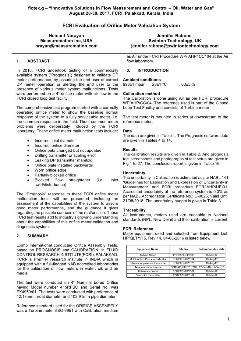
Uncertainty The uncertainty in Calibration is estimated as per NABL 141 ‘Guidelines for Estimation and Expression of Uncertainty in Measurement’ and FCRI procedure FCRI\AHP\UE\01. Accredited uncertainty of the reference system is 0.3% as per NABL Accreditation Certificate No.: C-0026, Valid Until 21/08/2018. The uncertainty budget is given in Table 3. Traceability All instruments, meters used are traceable to National standards (NPL, New Delhi) and their calibration is current. FCRI Reference Major equipment used and selected from Equipment List: HP/QLTY/15, Rev 14, 04-08-2016 is listed below.
Equipment Name File No. Calibration due date
Turbine Meter FCRI/AFL/HP/F06 16-Mar-17Multifunction Pressure Indicator FCRI/AFL/HP/P04 16-Aug-17Differencial pressure transmitter FCRI/AFL/HP/P25 16-Aug-17
Temperature indicators FCRI/AFL/HP/T01,T10 17-Feb-16, 15-Dec-16Universal counter FCRI/AFL/HP/C01 16-Mar-17
Dew point transmitter FCRI/AFL/HP/H04 16-Mar-17

PAGE 2 OF 15 PAGES
Table 1
Data of calibration
Table 2
Result of Calibration
PAGE 3 OF 15 PAGES
Table 3 Uncertainty budget

PAGE 4 OF 15 PAGES
Prognosis baseline data
Below is an example of Prognosis during the initial orifice calibration by FCRI. FCRI performed a calibration on the orifice meter in order to determine average Discharge Coefficient over a range of flows using the reference Turbine meter. Prognosis calculates three flow rate predictions using three different Differential Pressure measurements and calculations based on industry standards (in this case ISO 5167 2003) and well understood physical principles.
Fig. 1 Fig. 2
Fig. 3
During the initial FCRI calibration, prior to tests, the Prognosis results confirmed good Orifice meter performance. The meter geometry was as follows: Pipe Inlet Diameter = 103.91 mm Orifice Diameter = 62.18 mm Beta Ration ( 𝛽 )= 0.6 For each test presented in this report, the Orifice flow rate prediction error is either calculated directly where possible (this is possible in cases of incorrect meter geometry and error in Meter DP, presented in Part A) or estimated by comparing reported orifice meter flow rate to reference flow rate.

PAGE 5 OF 15 PAGES
Prognosis test data (Part A)
i) Input the meter inlet diameter to flow computer too high
Objective – Determine whether the DUT detects that the Orifice meter inlet diameter is entered too high. Criteria – DUT should react in accordance with the manufacturers’ specifications. A] Observed Measured Readings
a) Original pipe diameter, D= 103.91 mm b) Incorrectly entered pipe diameter, D = 130.91 mm c) Corresponding flow rate prediction error = - 4.64%.
Table 4
B] Results displayed on the Prognosis Screen Fig. 4
C] Conclusion: Prognosis can detect and guide the user to address if the in-use inlet diameter of orifice is high.
ii) Input the meter inlet diameter to flow computer too low
Objective – Determine whether the DUT detects that the Orifice meter inlet diameter is entered too low. Criteria – DUT should react in accordance with the manufacturers' specifications.
a) Original pipe diameter, D= 103.91 mm b) Incorrectly entered pipe diameter, D = 100 mm c) Corresponding flow rate prediction error = +1.3%
A] Observed Measured Readings Table 5

PAGE 6 OF 15 PAGES
B] Results displayed on the Prognosis Screen
Fig. 5 C] Conclusion: Prognosis can detect and guide the user to address if the in use inlet diameter of orifice is low.
iii) Input the meter orifice diameter to flow computer too high
Objective – Determine whether the DUT detects that the Orifice meter diameter is entered too high. Criteria – DUT should react in accordance with the manufacturers' specifications.
a) Original orifice diameter, d= 62.18 mm b) Incorrectly entered Orifice diameter, d = 63.18 mm c) Corresponding flow rate prediction error = +3.77%
A] Observed Measured Readings Table 6
B] Results displayed on the Prognosis Screen Fig. 6
C] Conclusion: Prognosis can detect and guide the user to address if the in-use orifice diameter is high.
iv) Input the meter orifice diameter to flow computer too low
Objective – Determine whether the DUT detects that the Orifice meter diameter is entered too low. Criteria – DUT should react in accordance with the manufacturers' specifications.
a) Original orifice diameter, d= 62.18 mm b) Incorrectly entered Orifice diameter, d = 61.18 mm c) Corresponding flow rate prediction error = -3.66%

PAGE 7 OF 15 PAGES
A] Observed Measured Readings
Table 7
B] Results displayed on the Prognosis Screen
Fig.7 C] Conclusion: Prognosis can detect and guide the user to address if the in-use orifice diameter is low.
v) Faulty DP reading (e.g., drifting transmitter, scaling error or
badly calibrated transmitter)
Objective – Determine whether the DUT detects a faulty DP reading. Criteria – DUT should react in accordance with the manufacturers' specifications. Method - Traditional DP mA scaling incorrectly adjusted (via internal push-buttons) from 4-20mA to 3.8-20mA to simulate a drifting or badly calibrated transmitter a) Traditional DP Reading in error by 4.65 mbar (-2.1%) b) Corresponding flow rate prediction error = -1.04%
A] Observed Measured Readings Table 8

PAGE 8 OF 15 PAGES
B] Traditional DP mA scaling adjusted slightly (via internal push-buttons) to simulate
a drifting or badly calibrated transmitter” Fig.8
C] Results displayed on the Prognosis Screen Fig. 9
D] Conclusion: Prognosis can detect and guide the user to address if there is an error in DP reading cause by (for example) incorrect scaling, faulty, drifting or badly calibrated transmitter.
vi) Faulty DP readings (Leaking Manifold)
Objective – Determine whether the DUT detects a faulty DP reading. Criteria – DUT should react in accordance with the manufacturers' specifications. Method – Open Equalisation valve anticlockwise (approx. 30 degrees) Approx. flow rate prediction error: -1.9% A] Observed Measured Readings
Table 9
B] Leaking Manifold/Impulse tubing. Criteria - Opening Equalization anticlockwise: 30 degrees (approx.)

PAGE 9 OF 15 PAGES
C] Results displayed on the Prognosis Screen
Fig 10 Fig. 11
D] Conclusion:
Prognosis can detect and guide the user to address if there is an error in DP reading cause by (for example) a leaking manifold or equalization valve not fully closed.
Prognosis test data (Part B)
i) Orifice plate installed backward
Objective – Determine whether the DUT detects that the Orifice meter inserted is backward. Criteria – DUT should react in accordance with the manufacturers' specifications. A] Observed Measured Readings
Table 10
B] Reversed orifice plate (Id No. FE-01)
Fig. 12 Fig. 13

PAGE 10 OF 15 PAGES
C] Results displayed on the Prognosis Screen
Fig. 14 D] Conclusion: The estimated flow rate prediction is a -17% under-reading. Prognosis can detect and guide the user to address if the orifice meter is installed backward.
ii) Worn orifice edge
Objective – Determine whether the DUT detects that the Orifice meter inserted is damaged. Criteria – DUT should react in accordance with the manufacturers' specifications. A] Observed Measured Readings
Table No. 11
B] Worn orifice plate (Id No. FE-02) Fig. 15 Fig. 16
C] Results displayed on the Prognosis Screen Fig. 17
D] Conclusion: The estimated flow rate prediction is a -3.1% under-reading. Prognosis can detect and guide the user to address if the orifice meter is damaged.

PAGE 11 OF 15 PAGES
iii) Partially blocked orifice
Objective – Determine whether the DUT detects that the Orifice meter is partially blocked. Criteria – DUT should react in accordance with the manufacturers' specifications. A] Observed Measured Readings
Table. 12
B] Partially blocked orifice (Id No. FE-03) Fig. 18 Fig. 19
C] Results displayed on the Prognosis Screen Fig. 20
D] Conclusion: The estimated flow rate prediction is +51% over-reading. Prognosis can detect and guide the user to address if there is any obstruction in meter throat.

PAGE 12 OF 15 PAGES
iv) Orifice installed with Smaller bore size (β = 0.5).
Objective – Determine whether the DUT detects that the inserted Orifice meter is of a smaller bore than expected Criteria – DUT should react in accordance with the manufacturers' specifications.
a) The plate is changed to a smaller beta by an operator but the flow computer is not updated. The calculations are based on a 0.6 beta plate but there is a 0.5 beta plate fitted in the orifice carrier.
A] Observed Measured Readings
Table 13
B] Orifice with Small bore size (Id No. FE-04)
Fig 21 Fig 22
C] Results displayed on the Prognosis Screen Fig. 23
D] Conclusion: The estimated flow rate prediction is +47% over-reading. Prognosis can detect and guide the user to address if the orifice is of a smaller bore than expected.
PAGE 13 OF 15 PAGES
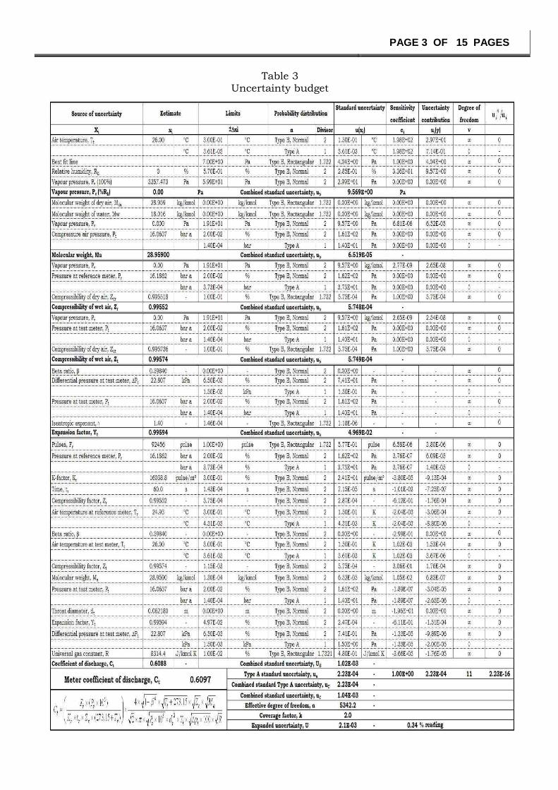
v) Flow straightener blocked (Upper side)
Objective – Determine whether the DUT detects that there is a flow disturbance. Criteria – DUT should react in accordance with the manufacturers' specifications. A] Observed Measured Readings
Table 14
B] Upper side blocked flow straightener
Fig 24
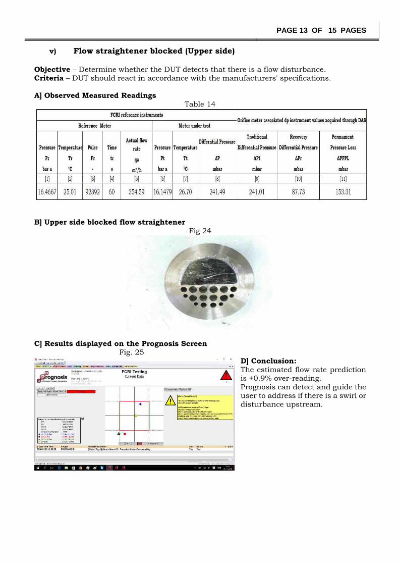
C] Results displayed on the Prognosis Screen Fig. 25
D] Conclusion: The estimated flow rate prediction is +0.9% over-reading.
Prognosis can detect and guide the user to address if there is a swirl or disturbance upstream.

PAGE 14 OF 15 PAGES
vi) Flow straightener blocked (lower side)
Objective – Determine whether the DUT detects that there is a flow disturbance. Criteria – DUT should react in accordance with the manufacturers' specifications. A] Observed Measured Readings
Table 15
B] Lower side blocked flow straightener
Fig. 26 C] Results displayed on the Prognosis Screen Fig. 27
D] Conclusion: The estimated flow rate prediction
is +0.5% over-reading. Prognosis can detect and guide the user to address if there is a swirl or disturbance in upstream.

PAGE 15 OF 15 PAGES
Conclusion Report:
Prognosis can detect and guide the user to address the most critical issues in the Differential Pressure Meters which are mostly undetected.
Table 16
Sr.no Test DetectionGuided user
to addressPass Result
1 Input the meter inlet diameter to
flow computer too high
Yes Yes
√
Prognosis can detect and guide
user to address if the in use inlet
diameter of orifice is high.
2 Input the meter inlet diameter to
flow computer too low
Yes Yes
√
Prognosis can detect and guide
user to address if the in use inlet
diameter of orifice is low.
3 Input the meter orifice diameter
to flow computer too high
Yes Yes
√
Prognosis can detect and guide
user to address if the in use orifice
diameter is high.
4 Input the meter orifice diameter
to flow computer too low
Yes Yes
√
Prognosis can detect and guide
user to address if the in use orifice
diameter is low.
5 Faulty DP reading (e.g., drifting
transmitter, scaling error or
badly calibrated transmitter)
Yes Yes
√
Prognosis can detect and guide
user to address if there is an error
in DP reading cause by (for
example) incorrect scaling, faulty,
drifting or badly calibrated
transmitter.
6 Faulty DP readings (Leaking
Manifold)
Yes Yes
√
Prognosis can detect and guide the
user to address if there is an error
in DP reading cause by (for
example) a leaking manifold or
equalization valve not fully closed.
7 Orifice plate installed backward Yes Yes
√
Prognosis can detect and guide the
user to address if the orifice is
installed backward.
8 Worn orifice edge Yes Yes
√
Prognosis can detect and guide the
user to address if the orifice meter
is damaged.
9 Partially blocked orifice Yes Yes
√
Prognosis can detect and guide the
user to address if there is any
obstruction in meter throat.
10 Orifice installed with smaller
bore size ( β = 0.5 )
Yes Yes
√
Prognosis can detect and guide the
user to address if the orifice meter
is of a smaller bore than expected.
11 Flow Straightener Blocked
11.1 Flow straightener blocked
(Upper Side)
Yes Yes
√
Prognosis can detect and guide the
user to address if there is a swirl or
disturbance upstream.
11.2 Flow straightener blocked
(Lower Side)
Yes Yes
√
Prognosis can detect and guide the
user to address if there is a swirl or
disturbance upstream.
TEST B
TEST A