Embed Size (px)
Citation preview
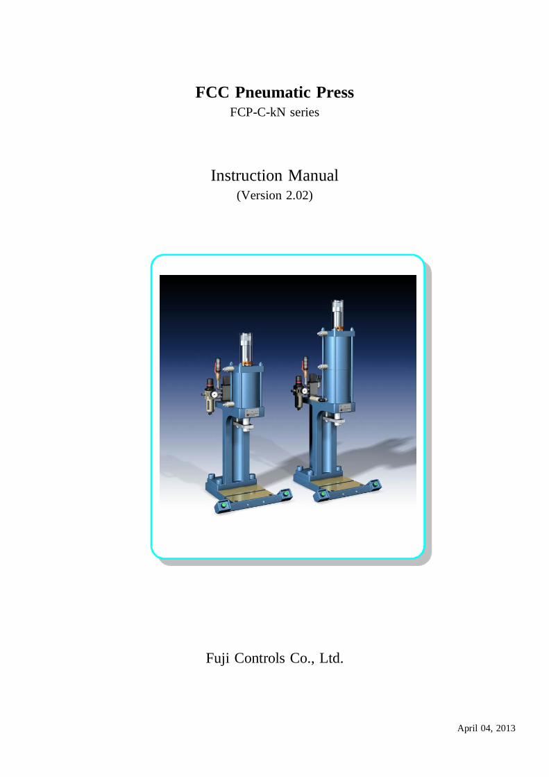
FCC Pneumatic PressFCP-C-kN series
Instruction Manual(Version 2.02)
Fuji Controls Co., Ltd.
April 04, 2013
We thank you for the purchase of our products.
In order to ensure proper equipment performance, please read this manual to the end before using our products.
This manual should be carefully stored and referred to when necessary. Please use this equipment for ever.
● In the case that this equipment is delivered to some other party, it is necessary to deliver the equipment together with
this instruction manual.
● This equipment is produced for use in Japan. In the case that it is used in other countries, you should observe the
laws and regulations related to safety in such countries.
Contents: Page
In order to be used safely: 1
It is necessary to observe: 1
Press component names: 3
………………………………………………………………………………………………<Additional explanation> 3
Unpacking 5
Installation and pre-operational procedures 5
……………………………………………………………………………………………………………<Installation> 5
……………………………………………………………………………………………<Pre-operational procedures> 5
Operation procedures: 6
………………………………………………………………………………Die matching (inching, inching motion) 6
Maintenance inspection: 7
Air circuit diagram: 8
Electric circuit diagram (wiring diagram): 8
Part table: 8
Dimensions drawings and weights: 9
Options: 10
Output diagram: 11
Air consumption amount: 11
1
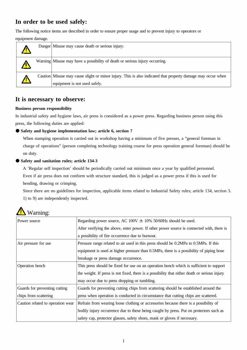
In order to be used safely:
The following notice items are described in order to ensure proper usage and to prevent injury to operators or
equipment damage.
Danger Misuse may cause death or serious injury.
Warning Misuse may have a possibility of death or serious injury occurring.
Caution Misuse may cause slight or minor injury. This is also indicated that property damage may occur when
equipment is not used safely.
It is necessary to observe:
Business person responsibility
In industrial safety and hygiene laws, air press is considered as a power press. Regarding business person using this
press, the following duties are applied:
● Safety and hygiene implementation law; article 6, section 7
When stamping operation is carried out in workshop having a minimum of five presses, a “general foreman in
charge of operations” (person completing technology training course for press operation general foreman) should be
on duty.
● Safety and sanitation rules; article 134-3
A ‘Regular self inspection’ should be periodically carried out minimum once a year by qualified personnel.
Even if air press does not conform with structure standard, this is judged as a power press if this is used for
bending, drawing or crimping.
Since there are no guidelines for inspection, applicable items related to Industrial Safety rules; article 134, section 3.
1) to 9) are independently inspected.
Warning:Power source Regarding power source, AC 100V ± 10% 50/60Hz should be used.
After verifying the above, enter power. If other power source is connected with, there is
a possibility of fire occurrence due to burnout.
Air pressure for use Pressure range related to air used in this press should be 0.2MPa to 0.5MPa. If this
equipment is used at higher pressure than 0.5MPa, there is a possibility of piping hose
breakage or press damage occurrence.
Operation bench This press should be fixed for use on an operation bench which is sufficient to support
the weight. If press is not fixed, there is a possibility that either death or serious injury
may occur due to press dropping or tumbling.
Guards for preventing cutting Guards for preventing cutting chips from scattering should be established around the
chips from scattering press when operation is conducted in circumstance that cutting chips are scattered.
Caution related to operation wear Refrain from wearing loose clothing or accessories because there is a possibility of
bodily injury occurrence due to these being caught by press. Put on protectors such as
safety cap, protector glasses, safety shoes, mask or gloves if necessary.
2
Press operation, maintenance or Only trained operators should carry out press pre-operational inspection, operation,
inspection by trained operator maintenance, die replacement or adjustment operation. It should be displayed for other
operators to notice that operation is being carrying out. The operation should be carried
out while verifying that other operators do not touch any component.
Prohibition of removing acrylic It is absolutely prohibited to remove acrylic cover for mechanical stopper or safety device
cover or safety device and or to change installation position. If press is operated without cover or safety device,
changing installation position there is a possibility of bodily injury occurrence due to a part of body being caught by
press.
Mechanical stopper adjustment Mechanical stopper adjustment should be carried out when press ram stops after rising
and no other operator should be in the vicinity of push button switch.
If push button switch is mistakenly pushed by other operator when adjustment is carried
out, there is a possibility of slight or serious injury occurrence due to a part of body
being caught by press.
In drawing operation that impact is added, mechanical stopper should not be used and
bottom dead center positioning while using die-set should be used instead.
Clearance between rotation Clearance between rotation stopping arm and cylinder bottom should be minimum
stopping arm and cylinder bottom 20mm.
portion In the case of narrow clearance, there is a possibility of slight or serious injury occurring
when press ram rises.
Rotation stopping arm is not equipped for adjusting press ram top dead center.
Press operation: For press operation, it should be carried out while verifying that no other operator
(1) Safety verification when touches any press portion and no obstacles are in the vicinity.
operation starts There is a possibility of bodily injury occurrence when preparation operation of die
setting up is carried out by multiple operators.
Do not make contact with mechanical stopper, jig, die or rotation stopping arm.
Press operation (2) For press operation, it is necessary to push button switches with both hands.
If one push button switch is operative or the switch is modified to foot switch, there is a
possibility of slight or serious injury occurrence due to a part of body being caught by jig
or die.
In the case that it is necessary to operate switch with one hand or foot, you may do so
only after installing photo type press safety device.
Piping is removed from air supply Do not touch jig or die when piping is removed from air supply inlet.
inlet If air supply is stopped, there is a possibility that press ram may descend. There is a
possibility of slight or serious injury occurrence due to a part of body being caught by jig
or die.
Modification/disassembly/repair Please do not modify, disassemble or repair this equipment.
In the case that any such work is carried out without our permission, we will have no
responsibility concerning any trouble or accidents.
3
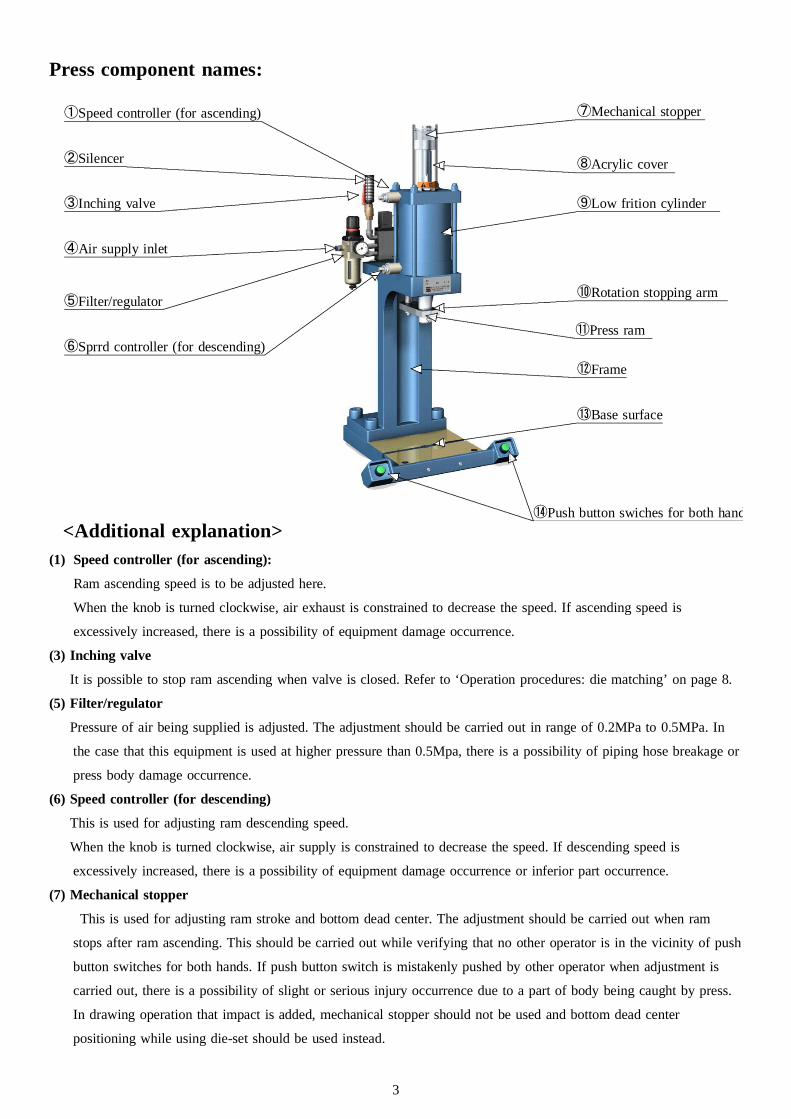
Press component names:
<Additional explanation>(1) Speed controller (for ascending):
Ram ascending speed is to be adjusted here.
When the knob is turned clockwise, air exhaust is constrained to decrease the speed. If ascending speed is
excessively increased, there is a possibility of equipment damage occurrence.
(3) Inching valve
It is possible to stop ram ascending when valve is closed. Refer to ‘Operation procedures: die matching’ on page 8.
(5) Filter/regulator
Pressure of air being supplied is adjusted. The adjustment should be carried out in range of 0.2MPa to 0.5MPa. In
the case that this equipment is used at higher pressure than 0.5Mpa, there is a possibility of piping hose breakage or
press body damage occurrence.
(6) Speed controller (for descending)
This is used for adjusting ram descending speed.
When the knob is turned clockwise, air supply is constrained to decrease the speed. If descending speed is
excessively increased, there is a possibility of equipment damage occurrence or inferior part occurrence.
(7) Mechanical stopper
This is used for adjusting ram stroke and bottom dead center. The adjustment should be carried out when ram
stops after ram ascending. This should be carried out while verifying that no other operator is in the vicinity of push
button switches for both hands. If push button switch is mistakenly pushed by other operator when adjustment is
carried out, there is a possibility of slight or serious injury occurrence due to a part of body being caught by press.
In drawing operation that impact is added, mechanical stopper should not be used and bottom dead center
positioning while using die-set should be used instead.
①Speed controller (for ascending)
②Silencer
③Inching valve
④Air supply inlet
⑤Filter/regulator
⑥Sprrd controller (for descending)
⑦Mechanical stopper
⑧Acrylic cover
⑨Low frition cylinder
⑩Rotation stopping arm
⑪Press ram
⑫Frame
⑬Base surface
⑭Push button swiches for both hand
4
(8) Acrylic cover
This is a safety cover for preventing hands from being caught by mechanical stopper. This should not be removed
other than when bottom dead center is adjusted. If equipment is operated without cover or safety device, there is a
possibility of bodily injury occurrence due to a part of body being caught by press.
(10) Rotation stopper
Clearance between rotation stopping arm and cylinder bottom should be minimum 10mm.
In the case of narrow clearance, there is a possibility of slight or serious injury occurrence due to a part of body
being caught by press when press ram rises.
Stopper arm is not equipped for adjusting press ram top dead center.
(14) Push button switches for both hands
If one push button switch is operative or the switch is modified to foot switch, there is a possibility of slight or
serious injury occurrence due to a part of body being caught by jig or die.
In the case that it is necessary to operate switch with one hand or foot, you may do so only after installing photo
type press safety device. (It is necessary to consult with us)
5
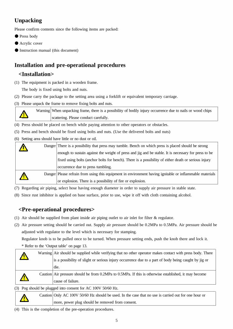
Unpacking
Please confirm contents since the following items are packed:
● Press body
● Acrylic cover
● Instruction manual (this document)
Installation and pre-operational procedures
<Installation>(1) The equipment is packed in a wooden frame.
The body is fixed using bolts and nuts.
(2) Please carry the package to the setting area using a forklift or equivalent temporary carriage.
(3) Please unpack the frame to remove fixing bolts and nuts.
Warning When unpacking frame, there is a possibility of bodily injury occurrence due to nails or wood chips
scattering. Please conduct carefully.
(4) Press should be placed on bench while paying attention to other operators or obstacles.
(5) Press and bench should be fixed using bolts and nuts. (Use the delivered bolts and nuts)
(6) Setting area should have little or no dust or oil.
Danger There is a possibility that press may tumble. Bench on which press is placed should be strong
enough to sustain against the weight of press and jig and be stable. It is necessary for press to be
fixed using bolts (anchor bolts for bench). There is a possibility of either death or serious injury
occurrence due to press tumbling.
Danger Please refrain from using this equipment in environment having ignitable or inflammable materials
or explosion. There is a possibility of fire or explosion.
(7) Regarding air piping, select hose having enough diameter in order to supply air pressure in stable state.
(8) Since rust inhibitor is applied on base surface, prior to use, wipe it off with cloth containing alcohol.
<Pre-operational procedures>(1) Air should be supplied from plant inside air piping outlet to air inlet for filter & regulator.
(2) Air pressure setting should be carried out. Supply air pressure should be 0.2MPa to 0.5MPa. Air pressure should be
adjusted with regulator to the level which is necessary for stamping.
Regulator knob is to be pulled once to be turned. When pressure setting ends, push the knob there and lock it.
* Refer to the ‘Output table’ on page 13.
Warning Air should be supplied while verifying that no other operator makes contact with press body. There
is a possibility of slight or serious injury occurrence due to a part of body being caught by jig or
die.
Caution Air pressure should be from 0.2MPa to 0.5MPa. If this is otherwise established, it may become
cause of failure.
(3) Pog should be plugged into consent for AC 100V 50/60 Hz.
Caution Only AC 100V 50/60 Hz should be used. In the case that no use is carried out for one hour or
more, power plug should be removed from consent.
(4) This is the completion of the pre-operation procedures.
6
Operation procedures:
<Operation starts. Try to operate press>
Die matching (inching, inching motion)
Warning Please verify that no other operator or obstacles are in the vicinity of press. There is a possibility of
slight or serious injury occurrence due to body or hands being caught by press.
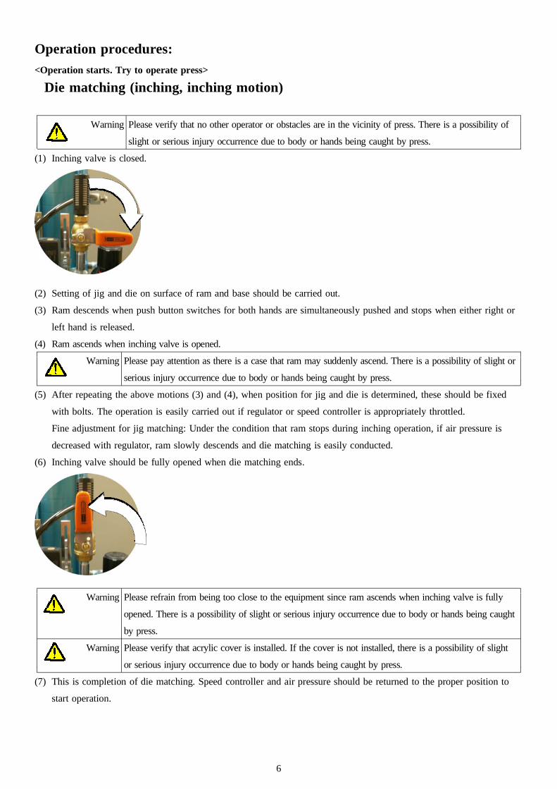
(1) Inching valve is closed.
(2) Setting of jig and die on surface of ram and base should be carried out.
(3) Ram descends when push button switches for both hands are simultaneously pushed and stops when either right or
left hand is released.
(4) Ram ascends when inching valve is opened.
Warning Please pay attention as there is a case that ram may suddenly ascend. There is a possibility of slight or
serious injury occurrence due to body or hands being caught by press.
(5) After repeating the above motions (3) and (4), when position for jig and die is determined, these should be fixed
with bolts. The operation is easily carried out if regulator or speed controller is appropriately throttled.
Fine adjustment for jig matching: Under the condition that ram stops during inching operation, if air pressure is
decreased with regulator, ram slowly descends and die matching is easily conducted.
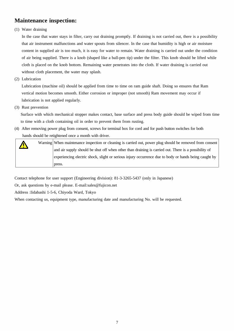
(6) Inching valve should be fully opened when die matching ends.
Warning Please refrain from being too close to the equipment since ram ascends when inching valve is fully
opened. There is a possibility of slight or serious injury occurrence due to body or hands being caught
by press.
Warning Please verify that acrylic cover is installed. If the cover is not installed, there is a possibility of slight
or serious injury occurrence due to body or hands being caught by press.
(7) This is completion of die matching. Speed controller and air pressure should be returned to the proper position to
start operation.
7
Maintenance inspection:
(1) Water draining
In the case that water stays in filter, carry out draining promptly. If draining is not carried out, there is a possibility
that air instrument malfunctions and water spouts from silencer. In the case that humidity is high or air moisture
content in supplied air is too much, it is easy for water to remain. Water draining is carried out under the condition
of air being supplied. There is a knob (shaped like a ball-pen tip) under the filter. This knob should be lifted while
cloth is placed on the knob bottom. Remaining water penetrates into the cloth. If water draining is carried out
without cloth placement, the water may splash.
(2) Lubrication
Lubrication (machine oil) should be applied from time to time on ram guide shaft. Doing so ensures that Ram
vertical motion becomes smooth. Either corrosion or improper (not smooth) Ram movement may occur if
lubrication is not applied regularly.
(3) Rust prevention
Surface with which mechanical stopper makes contact, base surface and press body guide should be wiped from time
to time with a cloth containing oil in order to prevent them from rusting.
(4) After removing power plug from consent, screws for terminal box for cord and for push button switches for both
hands should be retightened once a month with driver.
Warning When maintenance inspection or cleaning is carried out, power plug should be removed from consent
and air supply should be shut off when other than draining is carried out. There is a possibility of
experiencing electric shock, slight or serious injury occurrence due to body or hands being caught by
press.
Contact telephone for user support (Engineering division): 81-3-3265-5437 (only in Japanese)
Or, ask questions by e-mail please. E-mail:[email protected]
Address :Iidabashi 1-5-6, Chiyoda Ward, Tokyo
When contacting us, equipment type, manufacturing date and manufacturing No. will be requested.
8
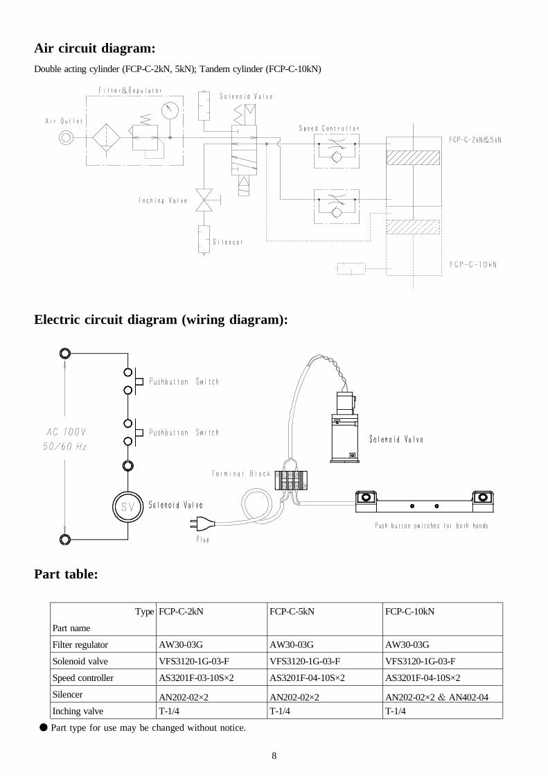
Air circuit diagram:
Double acting cylinder (FCP-C-2kN, 5kN); Tandem cylinder (FCP-C-10kN)
Electric circuit diagram (wiring diagram):
Part table:
Type FCP-C-2kN FCP-C-5kN FCP-C-10kN
Part name
Filter regulator AW30-03G AW30-03G AW30-03G
Solenoid valve VFS3120-1G-03-F VFS3120-1G-03-F VFS3120-1G-03-F
Speed controller AS3201F-03-10S×2 AS3201F-04-10S×2 AS3201F-04-10S×2
Silencer AN202-02×2 AN202-02×2 AN202-02×2 & AN402-04
Inching valve T-1/4 T-1/4 T-1/4
● Part type for use may be changed without notice.
9
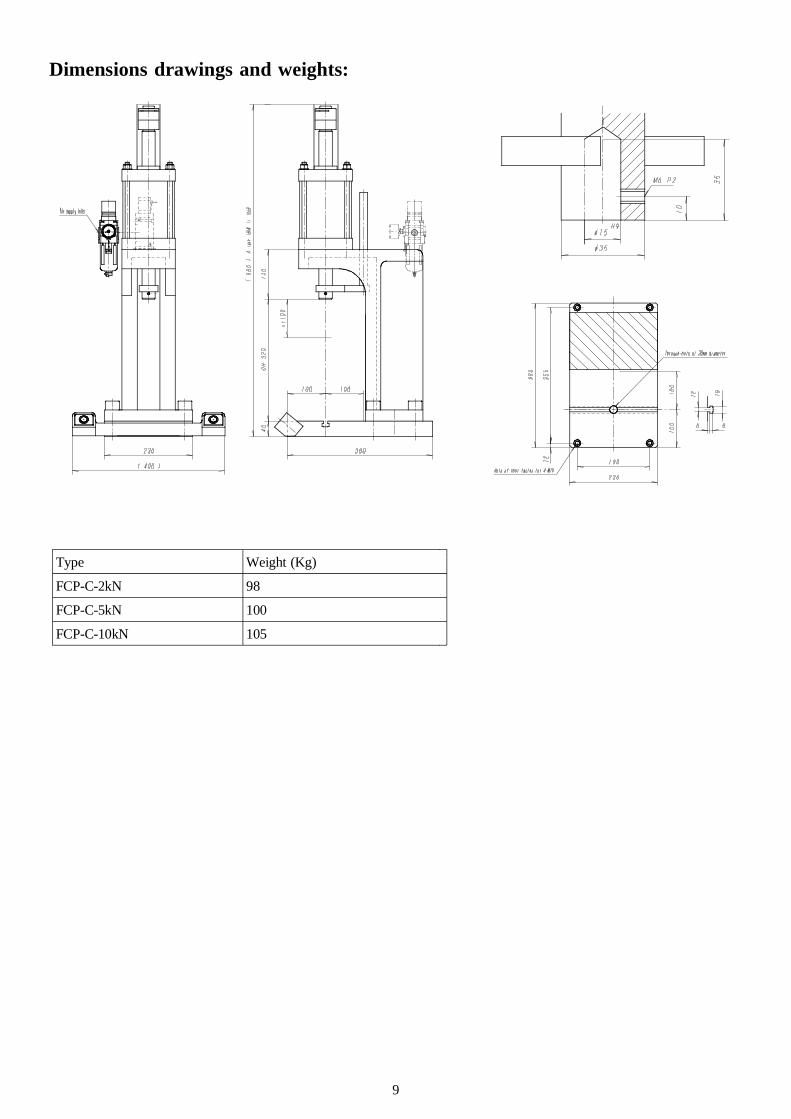
Dimensions drawings and weights:
Type Weight (Kg)
FCP-C-2kN 98
FCP-C-5kN 100
FCP-C-10kN 105
10
Options:
Regarding the Air-Press which you purchased, it is possible to install the following instruments as options. These will
display the power in quality control related to operation of crimping or press-fitting, quality improvement by controlling
stamping pressure or improvement of work efficiency. Since a catalog and related documents have been prepared, please
request them from us.
(1) Timer box
* Installation of circuit preventing from multiple shooting; * Counter integration; * Installation of die matching
circuit; * Time setting of stopping at bottom dead center is easy
(2) Low-high speed feed
It is possible for ram descending speed to switch between low- and high-speed by adding one electromagnetic valve.
(When timer box and controller are installed)
(3) Load control device
When stamping, it is possible to simultaneously carry out operation and judgment of OK/NG product by measuring
crimping or press-fitting force. This is useful for quality stabilization and cost reduction.
(4) Order-made press
In the case that the ready-made press is inadequate dimensions or time for re-designing is not enough, we can
support you with order-made presses made by Fuji Controls (FCC) with our excellent manufacturing performance.
11
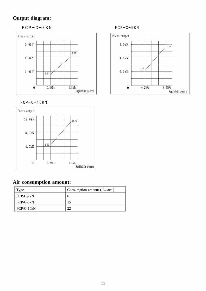
Output diagram:
Air consumption amount:
Type Consumption amount ( L (ANR) )
FCP-C-2kN 6
FCP-C-5kN 15
FCP-C-10kN 22
0 . 5 MPa0 . 2 MPa0
3 . 0 k N
2 . 0 k N
1 . 0 k N
0 . 5 MPa0 . 2 MPa0
5 . 6 5
2 . 2 6
6 . 0 k N
4 . 0 k N
2 . 0 k N
0 . 5 MPa0 . 2 MPa0
1 1 . 3 0
4 . 5 2
8 . 0 k N
1 2 . 0 k N
4 . 0 k N
FCP-C-2KN FCP-C-5KN
FCP-C-10KN
2 . 0 3
0 . 8 1
Suppl i ed ai r pressnre Suppl i ed ai r pressnre
Suppl i ed ai r pressnre
Press output Press output
Press output