Embed Size (px)
Citation preview

Report No.: BL-SZ1750232-701
2 / 112
Revision History
Version Issue Date Revisions Content
Rev. 01 Jun. 14, 2017 Initial Issue
TABLE OF CONTENTS
1 GENERAL INFORMATION .................................................................................................................... 5
1.1 Identification of the Testing Laboratory ..................................................................................... 5
1.2 Identification of the Responsible Testing Location .................................................................... 5
1.3 Test Environment Condition ..................................................................................................... 5
1.4 Announce ................................................................................................................................. 5
2 PRODUCT INFORMATION ................................................................................................................... 6
2.1 Applicant Information ................................................................................................................ 6
2.2 Manufacturer Information .......................................................................................................... 6
2.3 Factory Information ................................................................................................................... 6
2.4 General Description for Equipment under Test (EUT) ............................................................... 6
2.5 Ancillary Equipment .................................................................................................................. 7
2.6 Technical Information ............................................................................................................... 8
3 SUMMARY OF TEST RESULTS ........................................................................................................... 9
3.1 Test Standards ......................................................................................................................... 9
3.2 Device Category and SAR Limit ............................................................................................... 9
3.3 Test Result Summary ............................................................................................................. 11
3.4 Test Uncertainty ..................................................................................................................... 12
4 SAR MEASUREMENT SYSTEM ......................................................................................................... 13
4.1 Definition of Specific Absorption Rate (SAR) .......................................................................... 13
4.2 SATIMO SAR System ............................................................................................................ 13
5 SYSTEM VERIFICATION .................................................................................................................... 22
5.1 Antenna Port Test Requirement ............................................................................................. 22
5.2 Purpose of System Check ...................................................................................................... 22
5.3 System Check Setup .............................................................................................................. 22
6 EUT TEST POSITION CONFIGURATUONS ....................................................................................... 23
6.1 Head Exposure Conditions ..................................................................................................... 23

Report No.: BL-SZ1750232-701
3 / 112
6.2 Body-worn Position Conditions ............................................................................................... 24
6.3 Hotspot Mode Exposure Position Conditions .......................................................................... 25
7 SAR MEASUREMENT PROCEDURES ............................................................................................... 26
7.1 SAR Measurement Process Diagram ..................................................................................... 26
7.2 SAR Scan General Requirements .......................................................................................... 27
7.3 SAR Measurement Procedure ................................................................................................ 28
7.4 Area & Zoom Scan Procedures .............................................................................................. 28
8 CONDUCTED RF OUPUT POWER .................................................................................................... 29
8.1 GSM ....................................................................................................................................... 29
8.2 WCDMA ................................................................................................................................. 30
8.3 LTE......................................................................................................................................... 31
8.4 WIFI ........................................................................................................................................ 35
8.5 Bluetooth ................................................................................................................................ 37
9 EUT ANTENNA LOCATION SKETCH ................................................................................................. 38
9.1 SAR Test Exclusion Consider Table ....................................................................................... 39
9.2 10g Extremity Exposure Consider .......................................................................................... 42
10 TEST RESULTS .................................................................................................................................. 43
10.1 GSM 850 ................................................................................................................................ 43
10.2 GSM 1900 .............................................................................................................................. 43
10.3 WCDMA Band 2 ..................................................................................................................... 44
10.4 WCDMA Band 5 ..................................................................................................................... 44
10.5 LTE Band 2 (20MHz Bandwidth) ............................................................................................ 45
10.6 LTE Band 4 (20MHz Bandwidth) ............................................................................................ 46
10.7 LTE Band 7 (20MHz Bandwidth) ............................................................................................ 47
10.8 WIFI 2.4GHz ........................................................................................................................... 48
10.9 WIFI 5GHz .............................................................................................................................. 49
11 SAR Measurement Variability .............................................................................................................. 50
12 SIMULTANEOUS TRANSMISSION..................................................................................................... 51
12.1 Simultaneous Transmission Mode Consider ........................................................................... 51
12.2 Estimated SAR Calculation ..................................................................................................... 52
12.3 Sum SAR of Simultaneous Transmission ............................................................................... 53

Report No.: BL-SZ1750232-701
4 / 112
13 TEST EQUIPMENTS LIST .................................................................................................................. 55
ANNEX A SIMULATING LIQUID VERIFICATION RESULT .................................................................... 56
ANNEX B SYSTEM CHECK RESULT .................................................................................................... 57
ANNEX C TEST DATA ............................................................................................................................ 90
ANNEX D EUT EXTERNAL PHOTOS .................................................................................................. 112
ANNEX E SAR TEST SETUP PHOTOS ............................................................................................... 112
ANNEX F CALIBRATION REPORT ...................................................................................................... 112

Report No.: BL-SZ1750232-701
5 / 112
1 GENERAL INFORMATION
1.1 Identification of the Testing Laboratory
Company Name Shenzhen BALUN Technology Co., Ltd.
Address Block B, 1st FL, Baisha Science and Technology Park, Shahe Xi Road, Nanshan District, Shenzhen, Guangdong Province, P. R. China
Phone Number +86 755 6685 0100
1.2 Identification of the Responsible Testing Location
Test Location Shenzhen BALUN Technology Co., Ltd.
Address Block B, 1st FL, Baisha Science and Technology Park, Shahe Xi Road, Nanshan District, Shenzhen, Guangdong Province, P. R. China
Accreditation Certificate
The laboratory has been listed by Industry Canada to perform electromagnetic emission measurements. The recognition numbers of test site are 11524A-1. The laboratory has been listed by US Federal Communications Commission to perform electromagnetic emission measurements. The recognition numbers of test site are 832625. The laboratory is a testing organization accredited by China National Accreditation Service for Conformity Assessment (CNAS) according to ISO/IEC 17025. The accreditation certificate number is L6791.
Description
All measurement facilities used to collect the measurement data are located at Block B, FL 1, Baisha Science and Technology Park, Shahe Xi Road, Nanshan District, Shenzhen, Guangdong Province, P. R. China 518055
1.3 Test Environment Condition
Ambient Temperature 20 to 23℃ Ambient Relative Humidity
37 to 48%
Ambient Pressure 100 to 102KPa
1.4 Announce
(1) The test report reference to the report template version v2.2.
(2) The test report is invalid if not marked with the signatures of the persons responsible for preparing and approving the test report.
(3) The test report is invalid if there is any evidence and/or falsification.
(4) The results documented in this report apply only to the tested sample, under the conditions and modes of operation as described herein.
(5) This document may not be altered or revised in any way unless done so by BALUN and all revisions are duly noted in the revisions section.
(6) Content of the test report, in part or in full, cannot be used for publicity and/or promotional purposes without prior written approval from the laboratory.
Report No.: BL-SZ1750232-701
6 / 112
2 PRODUCT INFORMATION
2.1 Applicant Information
Applicant Honeywell International Inc Honeywell Sensing & Productivity Solutions
Address 9680 OLD BAILES RD FORT MILL SC 29707-7539
2.2 Manufacturer Information
Manufacturer Honeywell International Inc Honeywell Sensing & Productivity Solutions
Address 9680 OLD BAILES RD FORT MILL SC 29707-7539
2.3 Factory Information
Factory N/A Address N/A
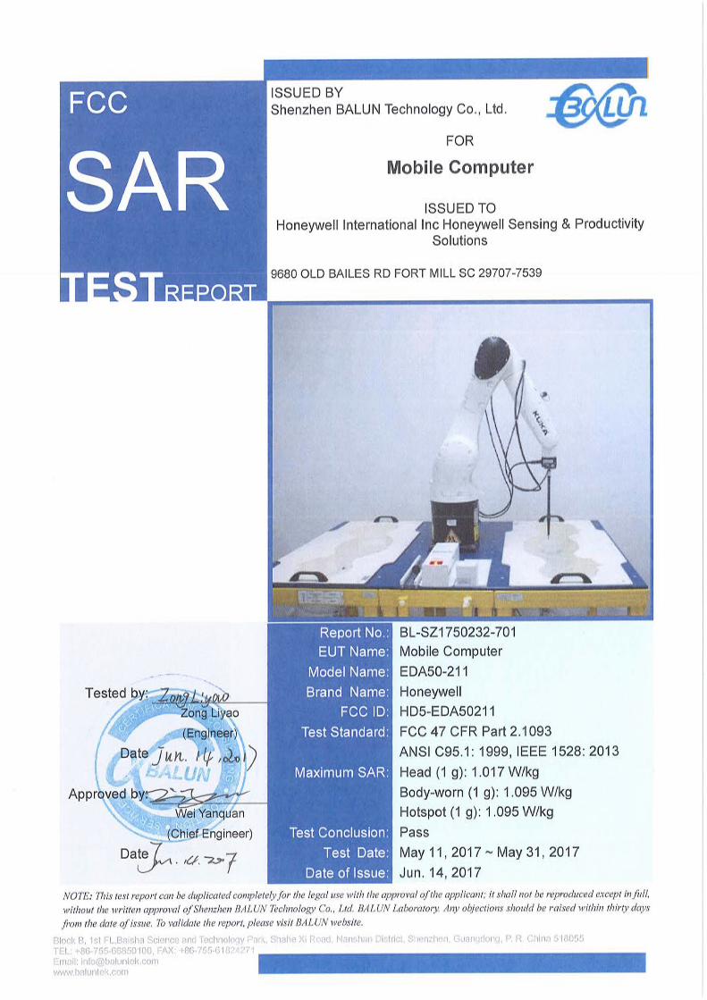
2.4 General Description for Equipment under Test (EUT)
EUT Name Mobile Computer Model Name Under Test EDA50-211 Series Model Name N/A Description of Model Name Differentiation
N/A
Hardware Version V2.0.0 Software Version 205.01.00.0006.eng Dimensions (Approx.) 153mm x 77mm x 17mm Weight (Approx.) N/A
Network and Wireless connectivity
2G Network GSM 850/1900;GPRS Class 12; EDGE Class 12; 3G Network WCDMA Band 2/5, HSDPA, HSUPA; 4G Network FDD LTE Band 2/4/7 WIFI 802.11a, 802.11b, 802.11g, 802.11n(HT20/40) Bluetooth, NFC, GPS

Report No.: BL-SZ1750232-701
7 / 112
2.5 Ancillary Equipment
Ancillary Equipment 1
Battery Brand Name N/A Model No. BAT-EDA50 Serial No. N/A Capacitance 4000 mAh Rated Voltage 3.8 V Limit Charge Voltage 4.35 V
Ancillary Equipment 2
Charger Brand Name N/A Model Name ADS-12B-06 05010E Rated Input 100-240 V , 50/60 Hz, 0.3 A Rated Output 5.0 V , 2.0 A

Report No.: BL-SZ1750232-701
8 / 112
2.6 Technical Information
The requirement for the following technical information of the EUT was tested in this report:
Operating Mode GSM, WCDMA, FDD-LTE, 2.4G WLAN, 5G WLAN, Bluetooth
Frequency Range
GSM 850 TX: 824 MHz ~ 849 MHz RX: 869 MHz ~ 894 MHz GSM 1900 TX: 1850 MHz ~ 1910 MHz RX: 1930 MHz ~ 1990 MHz WCDMA Band 2
TX: 1850 MHz ~ 1910 MHz RX: 1930 MHz ~ 1990 MHz
WCDMA Band 5
TX: 824 MHz ~ 849 MHz RX: 869 MHz ~ 894 MHz
LTE Band 2 TX: 1850 MHz ~ 1910 MHz RX: 1930 MHz ~ 1990 MHz LTE Band 4 TX: 1710 MHz ~ 1755 MHz RX: 2110 MHz ~ 2155 MHz LTE Band 7 TX: 2500 MHz ~ 2570 MHz RX: 2620 MHz ~ 2690 MHz 802.11b/g /n(HT20)
2400 MHz ~2483.5 MHz
802.11a/ /n(HT20/HT40)
5150 MHz~ 5250 MHz 5250 MHz~ 5350 MHz 5470 MHz~ 5725 MHz 5725 MHz~ 5850 MHz
Bluetooth 2400 MHz ~2483.5 MHz
Antenna Type WWAN: PIFA Antenna WLAN: PIFA Antenna Bluetooth: PIFA Antenna
DTM Not Support Hotspot Function Support Power Reduction Not Support Exposure Category General Population/Uncontrolled exposure EUT Stage Portable Device
Product Type
Production unit Identical prototype

Report No.: BL-SZ1750232-701
9 / 112
3 SUMMARY OF TEST RESULTS
3.1 Test Standards
No. Identity Document Title
1 47 CFR Part 2 Frequency Allocations and Radio Treaty Matters; General Rules and Regulations
2 ANSI/IEEE Std. C95.1-1999
IEEE Standard for Safety Levels with Respect to Human Exposure to Radio Frequency Electromagnetic Fields, 3 kHz to 300 GHz
3 IEEE Std. 1528-2013
Recommended Practice for Determining the Peak Spatial-Average Specific Absorption Rate (SAR) in the Human Head from Wireless Communications Devices: Measurement Techniques
4 FCC KDB 447498 D01 v06
Mobile and Portable Device RF Exposure Procedures and Equipment Authorization Policies
5 FCC KDB 941225 D01 v03r01
3G SAR MEAUREMENT PROCEDURES
6 FCC KDB 941225 D05 v02r05
SAR Evaluation Considerations for LTE Devices
7 FCC KDB 941225 D06 v02r01
SAR Evaluation Procedures for Portable Devices with Wireless Router Capabilities
8 FCC KDB 865664 D01 v01r04
SAR Measurement 100 MHz to 6 GHz
9 FCC KDB 865664 D02 v01r02
RF Exposure Reporting
10 FCC KDB 648474 D04 v01r03
SAR Evaluation Considerations for Wireless Handsets
11 KDB 248227 D01 v02r02
SAR Guidance for IEEE 802.11 (Wi-Fi) Transmitters
3.2 Device Category and SAR Limit
This device belongs to portable device category because its radiating structure is allowed to be used within 20 centimeters of the body of the user. Limit for General Population/Uncontrolled exposure should be applied for this device, it is 1.6 W/kg as averaged over any 1 gram of tissue.
Table of Exposure Limits:
Body Position SAR Value (W/Kg)
General Population/ Uncontrolled Exposure
Occupational/ Controlled Exposure
Whole-Body SAR (averaged over the entire body)
0.08 0.4
Partial-Body SAR (averaged over any 1 gram of tissue)
1.60 8.0
SAR for hands, wrists, feet and ankles (averaged over any 10 grams of tissue)
4.0 20.0

Report No.: BL-SZ1750232-701
10 / 112
NOTE: General Population/Uncontrolled: Locations where there is the exposure of individuals who have no knowledge or control of their exposure. General population/uncontrolled exposure limits are applicable to situations in which the general public may be exposed or in which persons who are exposed as a consequence of their employment may not be made fully aware of the potential for exposure or cannot exercise control over their exposure. Members of the general public would come under this category when exposure is not employment-related; for example, in the case of a wireless transmitter that exposes persons in its vicinity. Occupational/Controlled: Locations where there is exposure that may be incurred by persons who are aware of the potential for exposure, In general, occupational/controlled exposure limits are applicable to situations in which persons are exposed as a consequence of their employment, who have been made fully aware of the potential for exposure and can exercise control over their exposure. This exposure category is also applicable when the exposure is of a transient nature due to incidental passage through a location where the exposure levels may be higher than the general population/uncontrolled limits, but the exposed person is fully aware of the potential for exposure and can exercise control over his or her exposure by leaving the area or by some other appropriate means.

Report No.: BL-SZ1750232-701
11 / 112
3.3 Test Result Summary
3.3.1 Highest SAR (1 g Value)
Band
Maximum Scaled SAR
(W/kg)
Maximum Report SAR
(W/kg) Limit
(W/kg) Head Body-worn Hotspot Head Body-worn Hotspot
GSM 850 0.194 0.505 0.511
1.017 1.095 1.095 1.6
GSM 1900 0.149 0.165 0.334
WCDMA Band 2 0.365 0.354 0.527
WCDMA Band 5 0.295 0.592 0.592
LTE Band 2 0.462 0.604 0.772
LTE Band 4 0.539 0.531 0.631
LTE Band 7 0.178 1.095 1.095
2.4G WLAN 0.492 0.219 0.225
5.2G WLAN 1.017 0.327 0.424
5.6G WLAN 1.010 0.274 /
5.8G WLAN 0.875 0.239 0.349
Verdict Pass
Note: Only 2.4G WLAN, 5.2G WLAN (U-NII-1) and 5.8G WLAN (U-NII-3) support hotspot mode.
3.3.2 Highest Simultaneous SAR
Position Simultaneous Configuration Simultaneous SAR
(W/kg) Limit (W/kg) Verdict
Head LTE QPSK + 5G WLAN 1.556 1.6 Pass
Body-worn LTE QPSK + 5G WLAN 1.422 1.6 Pass
Hotspot Mode LTE QPSK + 5G WLAN 1.519 1.6 Pass

Report No.: BL-SZ1750232-701
12 / 112
3.4 Test Uncertainty
According to KDB 865664 D01, when the highest measured 1 g SAR within a frequency band is < 1.5 W/kg, the extensive SAR measurement uncertainty analysis is not required in SAR reports submitted for equipment approval. The maximum 1 g SAR for the EUT in this report is 1.095 W/kg, which is lower than 1.5 W/kg, so the extensive SAR measurement uncertainty analysis is not required in this report.

Report No.: BL-SZ1750232-701
13 / 112
4 SAR MEASUREMENT SYSTEM
4.1 Definition of Specific Absorption Rate (SAR)
SAR is related to the rate at which energy is absorbed per unit mass in an object exposed to a radio field. The SAR distribution in a biological body is complicated and is usually carried out by experimental techniques or numerical modeling. The standard recommends limits for two tiers of groups, occupational/controlled and general population/uncontrolled, based on a person’s awareness and ability to exercise control over his or her exposure. In general, occupational / controlled exposure limits are higher than the limits for general population /uncontrolled.
The SAR definition is the time derivative (rate) of the incremental energy (dW) absorbed by (dissipated in) an incremental mass (dm) contained in a volume element (dv) of a given density (ρ). The equation description is as below:
SAR is expressed in units of Watts per kilogram (W/kg) SAR measurement can be related to the electrical field in the tissue by
Where: σ is the conductivity of the tissue,
ρ is the mass density of the tissue and E is the RMS electrical field strength.
4.2 SATIMO SAR System
4.2.1 SATIMO SAR System Diagram
These measurements were performed with the automated near-field scanning system OPENSAR from SATIMO.

Report No.: BL-SZ1750232-701
14 / 112
The system is based on a high precision robot (working range: 850 mm), which positions the probes with a positional repeatability of better than ± 0.02 mm. Special E- and H-field probes have been developed for measurements close to material discontinuity, the sensors of which are directly loaded with a Schottky diode and connected via highly resistive lines to the data acquisition unit. The SAR measurements were conducted with dosimetric probe (manufactured by SATIMO), designed in the classical triangular configuration and optimized for dosimetric evaluation. The probe has been calibrated according to the procedure described in SAR standard with accuracy of better than ±10%. The spherical isotropy was evaluated with the procedure described in SAR standard and found to be better than ±0.25 dB. The phantom used was the SAM Phantom as described in FCC supplement C, IEEE P1528.
4.2.2 Robot
The SATIMO SAR system uses the high precision robots from KUKA. For the 6-axis controller system, the robot controller version (KUKA) from KUKA is used. The KUKA robot series have many features that are important for our application:
‧ High precision (repeatability ±0.035 mm) ‧ High reliability (industrial design) ‧ Jerk-free straight movements ‧ Low ELF interference (the closed metallic
construction shields against motor control fields)
4.2.3 E-Field Probe
For the measurements the Specific Dosimetric E-Field Probe SN 34/15 EPGO 265 with following specifications is used -- Dynamic range: 0.01-100 W/kg - Tip Diameter : 2.5 mm - Lower detection limit : 7 mW/kg (repeatability better than +/- 1mm) - Probe linearity: +/- 0.07 dB - Calibration range: 450 MHz to 5800 MHz for head & body simulating liquid.

Report No.: BL-SZ1750232-701
15 / 112
Angle between probe axis (evaluation axis) and surface normal line: less than 30°
E-Field Probe Calibration Process
Probe calibration is realized, in compliance with CENELEC EN 62209-1/-2 and IEEE 1528 std, with CALISAR, Antennessa proprietary calibration system. The calibration is performed with the IEC62209-1/2 annexe technique using reference guide at the five frequencies.
Where :
Pfw = Forward Power Pbw = Backward Power
a and b = Waveguide Dimensions ı = Skin Depth
Keithley configuration Rate = Medium; Filter =ON; RDGS=10; FILTER TYPE =MOVING AVERAGE; RANGE AUTO After each calibration, a SAR measurement is performed on a validation dipole and compared with a NPL calibrated probe, to verify it. The calibration factors, CF(N), for the 3 sensors corresponding to dipole 1, dipole 2 and dipole 3 are:

Report No.: BL-SZ1750232-701
16 / 112
CF(N)=SAR(N)/Vlin(N) (N=1,2,3) The linearised output voltage Vlin(N) is obtained from the displayed output voltage V(N) using Vlin(N)=V(N)*(1+V(N)/DCP(N)) (N=1,2,3) Where the DCP is the diode compression point in mV.

Report No.: BL-SZ1750232-701
17 / 112
4.2.4 Phantoms
For the measurements the Specific Anthropomorphic Mannequin (SAM) defined by the IEEE SCC-34/SC2 group is used. The phantom is a polyurethane shell integrated in a wooden table. The thickness of the phantom amounts to 2mm +/- 0.2mm. It enables the dosimetric evaluation of left and right phone usage and includes an additional flat phantom part for the simplified performance check. The phantom set-up includes a cover, which prevents the evaporation of the liquid.
Photo of Phantom SN 30/13 SAM103
Photo of Phantom SN 30/13 SAM104
Serial Number Positionner Material Permittivity Loss Tangent
SN 30/13 SAM103 Gelcoat with
fiberglass 3.4 0.02
SN 30/13 SAM104 Gelcoat with
fiberglass 3.4 0.02

Report No.: BL-SZ1750232-701
18 / 112
Serial Number Left Head Right Head Flat Part
SN 30/13 SAM103
2 2.00 2 2.03 1 2.09 3 2.02 3 2.05 2 2.10 4 2.04 4 2.04 3 2.09 5 2.04 5 2.07 4 2.11 6 2.02 6 2.07 5 2.11 7 2.01 7 2.09 6 2.09 8 2.04 8 2.10 7 2.11 9 2.02 9 2.09 - -
SN 30/13 SAM104
2 2.05 2 2.06 1 2.03 3 2.08 3 2.03 2 2.03 4 2.05 4 2.03 3 2.01 5 2.06 5 2.02 4 2.03 6 2.08 6 2.02 5 2.03 7 2.06 7 2.04 6 2.00 8 2.07 8 2.04 7 1.98 9 2.07 9 2.05 - -

Report No.: BL-SZ1750232-701
19 / 112
4.2.5 Device Holder
The SAR in the phantom is approximately inversely proportional to the square of the distance between the source and the liquid surface. For a source at 5 mm distance, a positioning uncertainty of ± 0.5 mm would produce a SAR uncertainty of ± 20 %. Accurate device positioning is therefore crucial for accurate and repeatable measurements. The positions in which the devices must be measured are defined by the standards.
Serial Number Holder Material Permittivity Loss Tangent
SN 25/13 MSH87 Deirin 3.7 0.005
SN 25/13 MSH88 Deirin 3.7 0.005
The positioning system allows obtaining cheek and tilting position with a very good accuracy. In compliance with CENELEC, the tilt angle uncertainty is lower than 1°.

Report No.: BL-SZ1750232-701
20 / 112
4.2.6 Simulating Liquid
For SAR measurement of the field distribution inside the phantom, the phantom must be filled with homogeneous tissue simulating liquid to a depth of at least 15 cm. For head SAR testing, the liquid height from the ear reference point (ERP) of the phantom to the liquid top surface is larger than 15 cm. For body SAR testing, the liquid height from the center of the flat phantom to the liquid top surface is larger than 15 cm. The nominal dielectric values of the tissue simulating liquids in the phantom and the tolerance of 5%.
Head Liquid Depth Body Liquid Depth
The following table gives the recipes for tissue simulating liquid and the theoretical Conductivity/Permittivity.
Head (Reference IEEE1528)
Frequency
(MHz)
Water
(%)
Sugar
(%)
Cellulose
(%)
Salt
(%)
Preventol
(%)
DGBE
(%)
Conductivity
σ (S/m)
Permittivity
ε
750 41.1 57.0 0.2 1.4 0.2 0 0.89 41.9 835 40.3 57.9 0.2 1.4 0.2 0 0.90 41.5 900 40.3 57.9 0.2 1.4 0.2 0 0.97 41.5
1800, 1900, 2000 55.2 0 0 0.3 0 44.5 1.4 40.0 2450 55.0 0 0 0.1 0 44.9 1.80 39.2 2600 54.9 0 0 0.1 0 45.0 1.96 39.0
Frequency(MHz) Water
(%)
Hexyl Carbitol
(%)
Triton X-100
(%)
Conductivity
σ (S/m)
Permittivity
ε
5200 62.52 17.24 17.24 4.66 36.0 5800 62.52 17.24 17.24 5.27 35.3
Body (From instrument manufacturer) Frequency
(MHz) Water
(%) Sugar
(%) Cellulose
(%) Salt
(%) Preventol
(%) DGBE
(%) Conductivity
σ (S/m) Permittivity
ε 750 51.7 47.2 0 0.9 0.1 0 0.96 55.5 835 50.8 48.2 0 0.9 0.1 0 0.97 55.2 900 50.8 48.2 0 0.9 0.1 0 1.05 55.0
1800, 1900, 2000 70.2 0 0 0.4 0 29.4 1.52 53.3 2450 68.6 0 0 0.1 0 31.3 1.95 52.7 2600 68.2 0 0 0.1 0 31.7 2.16 52.5

Report No.: BL-SZ1750232-701
21 / 112
Frequency(MHz) Water DGBE
(%)
Salt
(%)
Conductivity
σ (S/m)
Permittivity
ε 5200 78.60 21.40 / 5.54 47.86 5800 78.50 21.40 0.1 6.0 48.20

Report No.: BL-SZ1750232-701
22 / 112
5 SYSTEM VERIFICATION
5.1 Antenna Port Test Requirement
The SATIMO SAR system is equipped with one or more system validation kits. These units together with the predefined measurement procedures within the SATIMO software enable the user to conduct the system performance check and system validation. System validation kit includes a dipole, tripod holder to fix it underneath the flat phantom and a corresponding distance holder.
5.2 Purpose of System Check
The system performance check verifies that the system operates within its specifications. System and operator errors can be detected and corrected. It is recommended that the system performance check be performed prior to any usage of the system in order to guarantee reproducible results. The system performance check uses normal SAR measurements in a simplified setup with a well characterized source. This setup was selected to give a high sensitivity to all parameters that might fail or vary over time. The system check does not intend to replace the calibration of the components, but indicates situations where the system uncertainty is exceeded due to drift or failure.
5.3 System Check Setup
In the simplified setup for system evaluation, the EUT is replaced by a calibrated dipole and the power source is replaced by a continuous wave that comes from a signal generator. The calibrated dipole must be placed beneath the flat phantom section of the SAM twin phantom with the correct distance holder. The distance holder should touch the phantom surface with a light pressure at the reference marking and be oriented parallel to the long side of the phantom. The equipment setup is shown below:

Report No.: BL-SZ1750232-701
23 / 112
6 EUT TEST POSITION CONFIGURATUONS
According to KDB 648474 D04 Handset, handsets are tested for SAR compliance in head, body-worn accessory and other use configurations described in the following subsections.
6.1 Head Exposure Conditions
Head exposure is limited to next to the ear voice mode operations. Head SAR compliance is tested according to the test positions defined in IEEE Std 1528-2013 using the SAM phantom illustrated as below.
6.1.1 Define two imaginary lines on the handset
(a) The vertical center line passes through two points on the front side of the handset - the midpoint of the width w t of the handset at the level of the acoustic output, and the midpoint of the width w b of the bottom of the handset.
(b) The horizontal line is perpendicular to the vertical centerline and passes through the center of the acoustic output. The horizontal line is also tangential to the face of the handset at point A.
(c) The two lines intersect at point A. Note that for many handsets, point A coincides with the center of the acoustic output; however, the acoustic output may be located elsewhere on the horizontal line. Also note that the vertical centerline is not necessarily parallel to the front face of the handset, especially for clamshell handsets, handsets with flip covers, and other irregularly shaped handsets.
6.1.2 Cheek Position
(a) To position the device with the vertical center line of the body of the device and the horizontal line crossing the center piece in a plane parallel to the sagittal plane of the phantom. While maintaining the device in this plane, align the vertical center line with the reference plane containing the three ear and mouth reference point (M: Mouth, RE: Right Ear, and LE: Left Ear) and align the center of the ear piece with the line RE-LE.
(b) To move the device towards the phantom with the ear piece aligned with the line LE-RE until the phone touched the ear. While maintaining the device in the reference plane and maintaining the phone contact with the ear, move the bottom of the phone until any point on the front side is in contact with the cheek of the phantom or until contact with the ear is lost.
Report No.: BL-SZ1750232-701
24 / 112
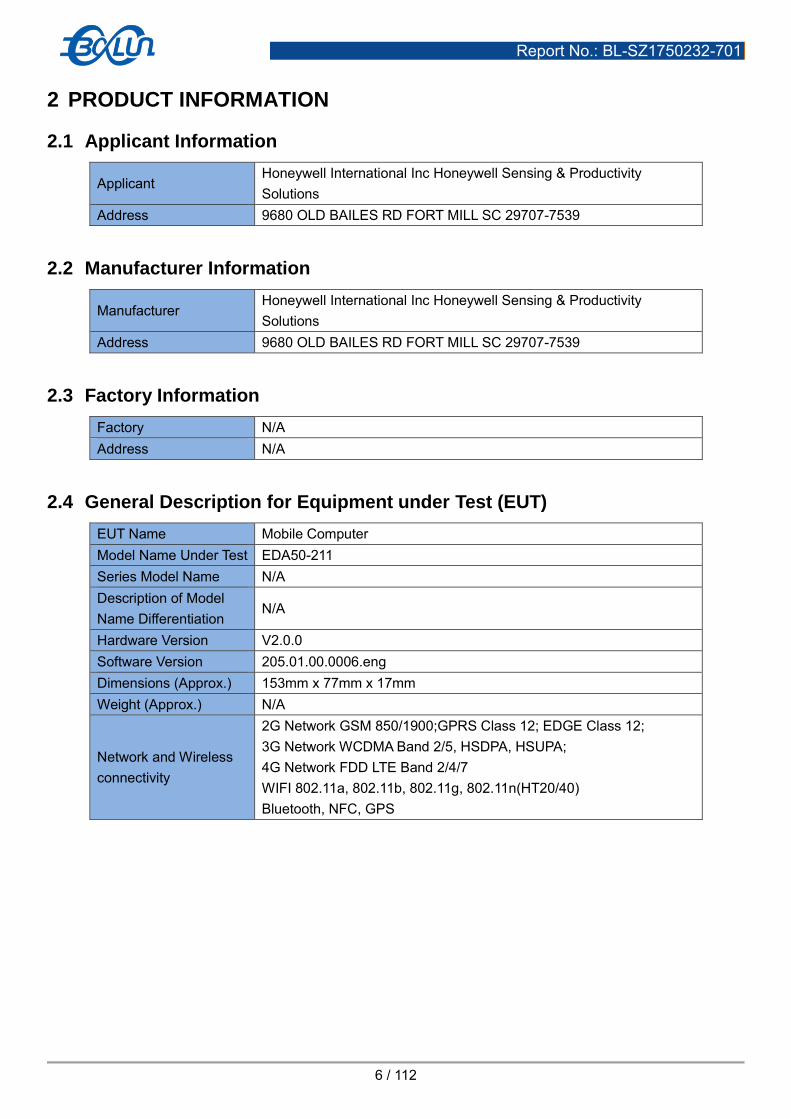
6.1.3 Tilted Position
(a) To position the device in the “cheek” position described above. (b) While maintaining the device the reference plane described above and pivoting against the ear, moves it
outward away from the mouth by an angle of 15 degrees or until contact with the ear is lost.
6.2 Body-worn Position Conditions
Body-worn accessory exposure is typically related to voice mode operations when handsets are carried in body-worn accessories. The body-worn accessory procedures in KDB 447498 are used to test for body-worn accessory SAR compliance, without a headset connected to it. This enables the test results for such configuration to be compatible with that required for hotspot mode when the body-worn accessory test separation distance is greater than or equal to that required for hotspot mode. When the reported SAR for a body-worn accessory, measured without a headset connected to the handset, is > 1.2 W/kg, the highest reported SAR configuration for that wireless mode and frequency band should be repeated for that body-worn accessory with a headset attached to the handset. Body-worn accessories that do not contain metallic or conductive components may be tested according to worst-case exposure configurations, typically according to the smallest test separation distance required for the group of body-worn accessories with similar operating and exposure characteristics. All body-worn accessories containing metallic components are tested in conjunction with the host device. Body-worn accessory SAR compliance is based on a single minimum test separation distance for all wireless and operating modes applicable to each body-worn accessory used by the host, and according to the relevant voice and/or data mode transmissions and operations. If a body-worn accessory supports voice only operations in its normal and expected use conditions, testing of data mode for body-worn compliance is not required. A conservative minimum test separation distance for supporting off-the-shelf body-worn accessories that may be acquired by

Report No.: BL-SZ1750232-701
25 / 112
users of consumer handsets is used to test for body-worn accessory SAR compliance. This distance is determined by the handset manufacturer, according to the requirements of Supplement C 01-01. Devices that are designed to operate on the body of users using lanyards and straps, or without requiring additional body-worn accessories, will be tested using a conservative minimum test separation distance <= 5 mm to support compliance.
6.3 Hotspot Mode Exposure Position Conditions
For handsets that support hotspot mode operations, with wireless router capabilities and various web browsing functions, the relevant hand and body exposure conditions are tested according to the hotspot SAR procedures in KDB 941225. A test separation distance of 10 mm is required between the phantom and all surfaces and edges with a transmitting antenna located within 25 mm from that surface or edge. When the form factor of a handset is smaller than 9 cm x 5 cm, a test separation distance of 5 mm (instead of 10 mm) is required for testing hotspot mode. When the separation distance required for body-worn accessory testing is larger than or equal to that tested for hotspot mode, in the same wireless mode and for the same surface of the phone, the hotspot mode SAR data may be used to support body-worn accessory SAR compliance for that particular configuration (surface).

Report No.: BL-SZ1750232-701
26 / 112
7 SAR MEASUREMENT PROCEDURES
7.1 SAR Measurement Process Diagram
Start
Power measurement
SAR Test consider
SAR Position Decided
Perform SAR Testing
SAR Result
Exclusion Thresholds
KDB447498
EUT FUCTION
Y N
Scaled SAR
TUNE-UP Description
Multiple Transmitting?
N
Max. SAR
Y Sum. SAR
Multiple Transmitting?
Y
Estimate SAR KDB447498
Not Required
Repeated SAR
KDB 865664
N
Max. SAR

Report No.: BL-SZ1750232-701
27 / 112
7.2 SAR Scan General Requirements
Probe boundary effect error compensation is required for measurements with the probe tip closer than half a probe tip diameter to the phantom surface. Both the probe tip diameter and sensor offset distance must satisfy measurement protocols; to ensure probe boundary effect errors are minimized and the higher fields closest to the phantom surface can be correctly measured and extrapolated to the phantom surface for computing 1-g SAR. Tolerances of the post-processing algorithms must be verified by the test laboratory for the scan resolutions used in the SAR measurements, according to the reference distribution functions specified in IEEE Std 1528-2013.
≤3GHz >3GHz Maximum distance from closest measurement point
(geometric center of probe sensors) to phantom surface 5±1 mm ½·δ·ln(2)±0.5 mm
Maximum probe angle from probe axis to phantom surface
normal at the measurement location 30°±1° 20°±1°
Maximum area scan spatial resolution: Δx Area , Δy Area
≤ 2 GHz: ≤ 15 mm
2 – 3 GHz: ≤ 12 mm
3–4 GHz: ≤ 12 mm
4 – 6 GHz: ≤ 10 mm
When the x or y dimension of the test device, in the
measurement plane orientation, is smaller than the above,
the measurement resolution must be ≤ the corresponding x
or y dimension of the test device with at least one
measurement point on the test device.
Maximum zoom scan spatial resolution: Δx Zoom , Δy Zoom ≤ 2 GHz: ≤ 8 mm
2 –3 GHz: ≤ 5 mm*
3–4 GHz: ≤ 5 mm*
4 – 6 GHz: ≤ 4 mm*
Maximum zoom scan
spatial resolution,
normal to phantom
surface
uniform grid: Δz Zoom (n) ≤ 5 mm 3–4 GHz: ≤ 4 mm
4–5 GHz: ≤ 3 mm
5–6 GHz: ≤ 2 mm
graded
grid
Δz Zoom (1):
between 1st two
points closest to
phantom surface
≤ 4 mm
3–4 GHz: ≤ 3 mm
4–5 GHz: ≤ 2.5 mm
5–6 GHz: ≤ 2 mm
Δz Zoom (n>1):
between subsequent
points
≤ 1.5·Δz Zoom (n-1)
Minimum zoom scan volume
x, y, z ≥30 mm
3–4 GHz: ≥ 28 mm
4–5 GHz: ≥ 25 mm
5–6 GHz: ≥ 22 mm
Note: 1. δ is the penetration depth of a plane-wave at normal incidence to the tissue medium; see draft standard IEEE P1528-
2011 for details.
2. * When zoom scan is required and the reported SAR from the area scan based 1-g SAR estimation procedures of KDB
447498 is ≤ 1.4 W/kg, ≤ 8 mm, ≤ 7 mm and ≤ 5 mm zoom scan resolution may be applied, respectively, for 2 GHz
to 3GHz, 3 GHz to 4 GHz and 4 GHz to 6 GHz.

Report No.: BL-SZ1750232-701
28 / 112
7.3 SAR Measurement Procedure
The following steps are used for each test position - Establish a call with the maximum output power with a base station simulator. The connection between the
mobile and the base station simulator is established via air interface - Measurement of the local E-field value at a fixed location. This value serves as a reference value for calculating
a possible power drift. - Measurement of the SAR distribution with a grid of 8 to 16mm * 8 to16 mm and a constant distance to the inner
surface of the phantom. Since the sensors cannot directly measure at the inner phantom surface, the values between the sensors and the inner phantom surface are extrapolated. With these values the area of the maximum SAR is calculated by an interpolation scheme.
- Around this point, a cube of 30 * 30 * 30 mm or 32 * 32 * 32 mm is assessed by measuring 5 or 8 * 5 or 8*4 or 5 mm. With these data, the peak spatial-average SAR value can be calculated.
7.4 Area & Zoom Scan Procedures
First Area Scan is used to locate the approximate location(s) of the local peak SAR value(s). The measurement grid within an Area Scan is defined by the grid extent, grid step size and grid offset. Next, in order to determine the EM field distribution in a three-dimensional spatial extension, Zoom Scan is required. The Zoom Scan is performed around the highest E-field value to determine the averaged SAR-distribution over 10 g. Area scan and zoom scan resolution setting follows KDB 865664 D01 quoted below. When the 1-g SAR of the highest peak is within 2 dB of the SAR limit, additional zoom scans are required for other peaks within 2 dB of the highest peak that have not been included in any zoom scan to ensure there is no increase in SAR.

Report No.: BL-SZ1750232-701
29 / 112
8 CONDUCTED RF OUPUT POWER
8.1 GSM
GSM 850 Band Burst Average Power(dBm) Frame-averaged power(dBm)
Channel 128 189 251 128 189 251
GSM (GMSK, 1-Slot) 32.53 32.50 32.51 23.53 23.50 23.51
GPRS (GMSK, 1-Slot) 32.54 32.53 32.50 23.54 23.53 23.50
GPRS (GMSK, 2-Slots) 30.69 30.38 30.40 24.69 24.38 24.40
GPRS (GMSK, 3-Slots) 28.20 28.24 28.16 23.94 23.98 23.90
GPRS (GMSK, 4-Slots) 27.12 27.07 27.02 24.12 24.07 24.02
EGPRS (8PSK, 1-Slot) 26.94 26.92 26.88 17.94 17.92 17.88
EGPRS (8PSK, 2-Slots) 26.84 26.77 26.73 20.84 20.77 20.73
EGPRS (8PSK, 3-Slots) 26.68 26.61 26.52 22.42 22.35 22.26
EGPRS (8PSK, 4-Slots) 24.58 24.50 24.42 21.58 21.50 21.42
GSM 1900 Band Burst Average Power(dBm) Frame-averaged power(dBm)
Channel 512 661 810 512 661 810
GSM (GMSK, 1-Slot) 29.51 29.49 29.47 20.51 20.49 20.47
GPRS (GMSK, 1-Slot) 29.54 29.41 29.28 20.54 20.41 20.28
GPRS (GMSK, 2-Slots) 27.08 26.97 26.93 21.08 20.97 20.93
GPRS (GMSK, 3-Slots) 25.05 25.03 24.96 20.79 20.77 20.70
GPRS (GMSK, 4-Slots) 23.86 23.67 23.48 20.86 20.67 20.48
EGPRS (8PSK, 1-Slot) 25.28 25.26 25.51 16.28 16.26 16.51
EGPRS (8PSK, 2-Slots) 25.17 25.13 25.36 19.17 19.13 19.36
EGPRS (8PSK, 3-Slots) 25.06 25.02 24.93 20.80 20.76 20.67
EGPRS (8PSK, 4-Slots) 23.83 23.67 24.13 20.83 20.67 21.13
Note 1: SAR testing was performed on the maximum frame-Peaked power mode.
Note 2: The frame-averaged power is linearly proportion to the slot number configured and it is linearly scaled the
maximum burst-averaged power based on time slots. The calculated method is shown as below:
Frame-averaged power = Burst averaged power (1 Tx Slot) - 9 dB
Frame-averaged power = Burst averaged power (2 Tx Slots) - 6 dB
Frame-averaged power = Burst averaged power (3 Tx Slots) - 4.26 dB
Frame-averaged power = Burst averaged power (4 Tx Slots) - 3 dB

Report No.: BL-SZ1750232-701
30 / 112
8.2 WCDMA
WCDMA Band Band 2 Band 5
Channel 9262 9400 9538 4132 4182 4233
RMC 12.2Kbps 23.56 23.63 23.53 22.18 22.25 22.21
HSDPA Subtest-1 21.56 22.04 21.14 22.20 22.18 22.23
HSDPA Subtest-2 21.42 21.64 21.19 21.92 21.95 21.97
HSDPA Subtest-3 21.10 21.14 21.58 21.75 21.70 21.73
HSDPA Subtest-4 21.69 21.67 21.75 21.58 21.43 21.53
HSUPA Subtest-1 21.75 21.54 21.43 22.26 22.24 22.21
HSUPA Subtest-2 21.53 21.35 21.26 21.95 21.97 21.93
HSUPA Subtest-3 21.15 21.09 21.08 21.73 21.70 21.75
HSUPA Subtest-4 21.02 20.97 20.96 21.49 21.52 21.47
HSUPA Subtest-5 20.87 20.86 20.85 21.38 21.36 21.39

Report No.: BL-SZ1750232-701
31 / 112
8.3 LTE
FDD LTE Band 2
Bandwidth
(MHz)
RB Set Power (dBm)
QPSK 16QAM
Channel 18700 18900 19100 18700 18900 19100
20MHz
1 (RB_Pos:0) 23.46 23.18 23.37 23.18 22.83 23.56
1 (RB_Pos:49) 22.66 23.20 23.38 23.09 22.84 23.51
1 (RB_Pos:99) 22.64 22.88 23.27 22.78 22.67 23.24
50 (RB_Pos:0) 22.44 22.69 23.19 22.47 22.62 23.04
50 (RB_Pos:24) 22.35 22.46 22.92 22.18 22.47 22.78
50 (RB_Pos:49) 22.33 22.38 22.77 22.16 22.40 22.75
100 (RB_Pos:0) 22.12 22.19 22.45 21.96 22.15 22.74
Bandwidth
(MHz)
RB Set Power (dBm)
QPSK 16QAM
Channel 18675 18900 19125 18675 18900 19125
15MHz
1 (RB_Pos:0) 22.85 22.53 23.03 21.76 21.54 21.96
1 (RB_Pos:37) 22.87 22.51 23.01 21.88 21.63 21.89
1 (RB_Pos:74) 22.59 22.39 22.90 21.78 21.42 21.83
36 (RB_Pos:0) 22.28 22.13 22.76 21.76 21.12 21.72
36 (RB_Pos:18) 22.04 21.81 22.67 21.66 20.83 21.48
36 (RB_Pos:37) 21.83 21.58 22.59 21.52 20.80 21.33
75 (RB_Pos:0) 21.81 21.55 22.47 21.33 20.59 21.01
Bandwidth
(MHz)
RB Set Power (dBm)
QPSK 16QAM
Channel 18650 18900 19150 18650 18900 19150
10MHz
1 (RB_Pos:0) 23.03 22.56 23.04 21.98 21.65 22.06
1 (RB_Pos:24) 23.04 22.57 23.03 21.84 21.58 21.99
1 (RB_Pos:49) 22.76 22.37 22.89 21.51 21.35 21.88
25 (RB_Pos:0) 22.60 22.18 22.73 21.40 21.24 21.83
25 (RB_Pos:12) 22.28 22.15 22.67 21.37 21.19 21.51
25 (RB_Pos:24) 22.25 21.87 22.63 21.12 20.98 21.27
50 (RB_Pos:0) 22.14 21.62 22.41 21.00 20.71 21.17
Bandwidth
(MHz)
RB Set Power (dBm)
QPSK 16QAM
Channel 18625 18900 19175 18625 18900 19175
5MHz
1 (RB_Pos:0) 23.01 22.48 23.12 22.13 21.59 22.08
1 (RB_Pos:12) 22.99 22.46 23.13 22.11 21.5 22.3
1 (RB_Pos:24) 22.95 22.16 22.84 21.97 21.48 22.12
12 (RB_Pos:0) 22.62 21.89 22.77 21.90 21.47 21.97
12 (RB_Pos:6) 22.43 21.84 22.59 21.58 21.42 21.76
12 (RB_Pos:11) 22.39 21.70 22.41 21.44 21.19 21.67
25 (RB_Pos:0) 22.17 21.40 22.11 21.41 21.17 21.55
Bandwidth
(MHz) RB Set
Power (dBm)
QPSK 16QAM

Report No.: BL-SZ1750232-701
32 / 112
Channel 18615 18900 19185 18615 18900 19185
3MHz
1 (RB_Pos:0) 23.09 22.49 23.13 21.98 21.69 22.11
1 (RB_Pos:7) 23.12 22.5 23.14 22.09 21.71 22.08
1 (RB_Pos:14) 22.88 22.42 23.09 21.98 21.67 21.92
8 (RB_Pos:0) 22.84 22.40 22.94 21.81 21.50 21.65
8 (RB_Pos:4) 22.80 22.11 22.73 21.78 21.46 21.35
8 (RB_Pos:7) 22.75 21.88 22.47 21.49 21.31 21.30
15 (RB_Pos:0) 22.54 21.82 22.17 21.28 21.06 20.99
Bandwidth
(MHz)
RB Set Power (dBm)
QPSK 16QAM
Channel 18607 18900 19193 18607 18900 19193
1.4MHz
1 (RB_Pos:0) 23.01 22.45 23.15 22.01 21.81 21.91
1 (RB_Pos: 2) 22.99 22.44 23.13 22.02 21.71 21.95
1 (RB_Pos:5) 22.79 22.33 22.94 21.85 21.59 21.83
3 (RB_Pos:0) 22.65 22.20 22.86 21.61 21.31 21.79
3 (RB_Pos:1) 22.60 22.07 22.75 21.40 21.04 21.58
3 (RB_Pos:2) 22.53 21.97 22.47 21.31 20.95 21.33
6 (RB_Pos:0) 22.28 21.87 22.27 21.07 20.82 21.27
FDD LTE Band 4
Bandwidth
(MHz)
RB Set Power (dBm)
QPSK 16QAM
Channel 20050 20175 20300 20050 20175 20300
20MHz
1 (RB_Pos:0) 23.81 23.84 23.45 21.80 22.04 22.36
1 (RB_Pos:49) 23.80 23.86 23.44 21.91 21.97 22.40
1 (RB_Pos:99) 23.77 23.55 23.27 21.82 21.87 22.17
50 (RB_Pos:0) 23.55 23.41 23.08 21.74 21.69 22.17
50 (RB_Pos:24) 23.45 23.28 23.06 21.56 21.51 21.98
50 (RB_Pos:49) 23.20 23.20 23.06 21.23 21.43 21.86
100 (RB_Pos:0) 23.11 22.88 22.80 21.01 21.14 21.79
Bandwidth
(MHz)
RB Set Power (dBm)
QPSK 16QAM
Channel 20025 20175 20325 20025 20175 20325
15MHz
1 (RB_Pos:0) 22.74 22.87 22.81 21.76 21.93 22.34
1 (RB_Pos:37) 22.73 22.90 22.82 21.74 21.92 22.35
1 (RB_Pos:74) 22.58 22.88 22.81 21.44 21.89 22.25
36 (RB_Pos:0) 22.41 22.72 22.49 21.41 21.58 22.12
36 (RB_Pos:18) 22.10 22.42 22.39 21.26 21.39 22.01
36 (RB_Pos:37) 22.02 22.14 22.16 21.14 21.16 21.79
75 (RB_Pos:0) 21.97 21.94 21.89 20.90 21.07 21.67
Bandwidth
(MHz)
RB Set Power (dBm)
QPSK 16QAM
Channel 20000 20175 20350 20000 20175 20350
10MHz 1 (RB_Pos:0) 22.59 22.92 23.4 21.65 21.92 22.21

Report No.: BL-SZ1750232-701
33 / 112
1 (RB_Pos:24) 22.60 22.91 23.3 21.64 21.83 22.36
1 (RB_Pos:49) 22.42 22.69 23.05 21.59 21.77 22.29
25 (RB_Pos:0) 22.41 22.42 22.79 21.42 21.52 22.16
25 (RB_Pos:12) 22.36 22.37 22.56 21.15 21.40 22.09
25 (RB_Pos:24) 22.05 22.06 22.32 21.12 21.11 21.79
50 (RB_Pos:0) 22.02 22.04 22.13 21.11 21.05 21.62
Bandwidth
(MHz)
RB Set Power (dBm)
QPSK 16QAM
Channel 19975 20175 20375 19975 20175 20375
5MHz
1 (RB_Pos:0) 22.46 22.88 23.37 21.63 21.89 22.53
1 (RB_Pos:12) 22.45 22.86 23.36 21.65 21.92 22.32
1 (RB_Pos:24) 22.28 22.58 23.23 21.39 21.89 22.20
12 (RB_Pos:0) 22.22 22.55 23.04 21.33 21.63 22.02
12 (RB_Pos:6) 21.93 22.39 22.96 21.02 21.34 21.86
12 (RB_Pos:11) 21.89 22.08 22.69 20.82 21.12 21.57
25 (RB_Pos:0) 21.66 21.95 22.37 20.64 20.88 21.44
Bandwidth (MHz)
RB Set Power (dBm)
QPSK 16QAM
Channel 19965 20175 20385 19965 20175 20385
3.0MHz
1 (RB_Pos:0) 22.43 22.89 23.33 21.59 21.69 22.40
1 (RB_Pos:7) 22.57 22.88 23.32 21.58 21.68 22.37
1 (RB_Pos:14) 22.28 22.86 23.05 21.30 21.40 22.27
8 (RB_Pos:0) 22.13 22.79 22.96 21.03 21.10 22.07
8 (RB_Pos:4) 22.08 22.75 22.66 20.96 20.89 21.78
8 (RB_Pos:7) 21.92 22.53 22.34 20.71 20.75 21.48
15 (RB_Pos:0) 21.68 22.36 22.34 20.70 20.66 21.20
Bandwidth
(MHz)
RB Set Power (dBm)
QPSK 16QAM
Channel 19957 20175 20393 19957 20175 20393
1.4MHz
1 (RB_Pos:0) 22.56 22.75 23.31 21.69 22.07 22.03
1 (RB_Pos:2) 22.54 22.74 23.30 21.89 22.08 22.22
1 (RB_Pos:5) 22.34 22.50 23.00 21.89 21.76 22.14
3 (RB_Pos:0) 22.19 22.35 22.74 21.84 21.53 21.83
3 (RB_Pos:1) 21.94 22.20 22.66 21.53 21.38 21.79
3 (RB_Pos:2) 21.64 22.15 22.62 21.29 21.15 21.70
6 (RB_Pos:0) 21.38 21.83 22.59 21.02 21.09 21.52

Report No.: BL-SZ1750232-701
34 / 112
FDD LTE Band 7
Bandwidth
(MHz)
RB Set Power (dBm)
QPSK 16QAM
Channel 20850 21100 21350 20850 21100 21350
20MHz
1 (RB_Pos:0) 23.21 23.60 23.24 22.79 23.61 23.31
1 (RB_Pos:49) 23.23 23.57 23.07 22.75 23.65 23.08
1 (RB_Pos:99) 23.01 23.46 22.98 22.63 23.46 22.86
50 (RB_Pos:0) 22.91 23.25 22.87 22.52 23.47 22.65
50 (RB_Pos:24) 22.71 23.07 22.65 22.32 23.28 22.57
50 (RB_Pos:49) 22.59 22.89 22.58 22.23 23.08 22.38
100 (RB_Pos:0) 22.43 22.66 22.43 22.18 22.99 22.26
Bandwidth
(MHz)
RB Set Power (dBm)
QPSK 16QAM
Channel 20825 21100 21375 20825 21100 21375
15MHz
1 (RB_Pos:0) 22.99 22.95 22.95 21.84 22.22 21.79
1 (RB_Pos:37) 22.96 22.97 22.94 21.88 21.88 21.85
1 (RB_Pos:74) 22.65 22.79 22.87 21.88 21.70 21.58
36 (RB_Pos:0) 22.44 22.62 22.65 21.53 21.60 21.49
36 (RB_Pos:18) 22.27 22.38 22.40 21.30 21.38 21.17
36 (RB_Pos:37) 22.11 22.31 22.08 21.32 21.20 20.90
75 (RB_Pos:0) 21.87 22.28 22.06 21.29 20.75 20.60
Bandwidth
(MHz)
RB Set Power (dBm)
QPSK 16QAM
Channel 20800 21100 21400 20800 21100 21400
10MHz
1 (RB_Pos:0) 22.96 22.98 22.98 21.97 22.05 22.03
1 (RB_Pos:24) 22.97 23.08 23.01 21.92 22.03 21.97
1 (RB_Pos:49) 22.81 22.92 23.00 21.66 21.71 21.92
25 (RB_Pos:0) 22.46 22.64 22.70 21.50 21.44 21.70
25 (RB_Pos:12) 22.31 22.41 22.51 21.47 21.33 21.49
25 (RB_Pos:24) 21.88 22.33 22.26 21.27 21.18 21.33
50 (RB_Pos:0) 21.80 22.06 22.06 21.25 21.22 21.28
Bandwidth
(MHz)
RB Set Power (dBm)
QPSK 16QAM
Channel 20775 21100 21425 20775 21100 21425
5MHz
1 (RB_Pos:0) 22.94 22.98 23.02 21.94 22.13 22.01
1 (RB_Pos:12) 22.95 22.95 23.01 21.88 22.09 22.00
1 (RB_Pos:24) 22.81 22.85 22.77 21.90 22.08 21.97
12 (RB_Pos:0) 22.60 22.75 22.69 21.71 21.89 21.84
12 (RB_Pos:6) 22.46 22.44 22.69 21.44 21.71 21.53
12 (RB_Pos:11) 22.24 22.32 22.69 21.22 21.62 21.23
25 (RB_Pos:0) 21.98 22.14 22.59 21.12 21.45 21.07

Report No.: BL-SZ1750232-701
35 / 112
8.4 WIFI
8.4.1 2.4GWIFI
Band
(GHz) Mode Channel
Freq.
(MHz)
Avg. Power
(dBm)
SAR Test
Require.
2.4
(2.4~2.4835)
802.11b
1 2412 18.17 No
6 2437 18.36 Yes
11 2462 15.76 No
802.11g
1 2412 15.32 No
6 2437 15.19 No
11 2462 10.45 No
802.11n(HT20)
1 2412 13.13 No
6 2437 13.48 No
11 2462 10.91 No

Report No.: BL-SZ1750232-701
36 / 112
8.4.2 5GWIFI
Band
(GHz) Mode Channel
Freq.
(MHz)
Avg. Power
(dBm)
SAR Test
Require.
5.2
(5.15~5.25)
802.11a
36 5180 10.07 No
44 5220 10.70 Yes
48 5240 10.48 No
802.11n(HT20)
36 5180 9.97 No
44 5220 10.46 No
48 5240 9.91 No
802.11n(HT40) 38 5190 9.85 No
46 5230 10.32 No
5.3
(5.25~5.35)
802.11a
52 5260 10.61 No
60 5300 10.42 No
64 5320 10.25 No
802.11n(HT20)
52 5260 10.32 No
60 5300 10.05 No
64 5320 9.84 No
802.11n(HT40) 54 5270 9.91 No
62 5310 10.50 No
5.6
(5.47~5.725)
802.11a
100 5500 11.32 No
120 5600 11.51 Yes
140 5700 9.35 No
802.11n(HT20)
100 5500 11.22 No
120 5600 11.26 No
140 5700 8.88 No
802.11n(HT40)
102 5510 9.26 No
118 5590 11.27 No
134 5670 9.35 No
5.8
(5.725~5.850)
802.11a
149 5745 10.51 No
157 5785 10.54 Yes
165 5825 10.39 No
802.11n(HT20)
149 5745 10.12 No
157 5785 10.20 No
165 5825 9.91 No
802.11n(HT40) 151 5755 10.24 No
159 5795 10.24 No

Report No.: BL-SZ1750232-701
37 / 112
8.5 Bluetooth
Mode GFSK π/4-DQPSK
Channel 0 39 78 0 39 78
Frequency (MHz) 2402 2441 2480 2402 2441 2480
Peak Power (dBm) 4.95 6.54 4.88 2.78 4.32 2.81
Mode 8-DPSK BLE
Channel 0 39 78 0 19 39
Frequency (MHz) 2402 2441 2480 2402 2440 2480
Peak Power (dBm) 2.76 4.33 3.19 -0.99 0.00 -1.01
Report No.: BL-SZ1750232-701
38 / 112
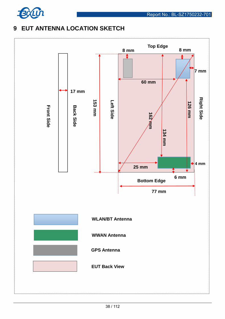
9 EUT ANTENNA LOCATION SKETCH
Fro
nt S
ide
Bac
k S
ide
77 mm
Top Edge
Le
ft Sid
e
15
3 m
m
Rig
ht S
ide
4 mm
8 mm
13
4 m
m
16
2 m
m
8 mm
6 mm
25 mm
Bottom Edge
WLAN/BT Antenna
WWAN Antenna
GPS Antenna
EUT Back View
17 mm
7 mm
60 mm
12
6 m
m

Report No.: BL-SZ1750232-701
39 / 112
9.1 SAR Test Exclusion Consider Table
According with FCC KDB 447498 D01, Appendix A, <SAR Test Exclusion Thresholds for 100 MHz – 6 GHz and ≤ 50 mm> Table, this Device SAR test configurations consider as following :
Band Mode Max. Peak Power
Test Position Configurations
Head Front/
Back
Left
Edge
Right
Edge
Top
Edge
Bottom
Edge dBm mW
GSM 850
Distance to User <5mm <5 mm 25 mm <5 mm 134 mm 6mm
Voice 33.50 2238.72 Yes Yes Yes Yes No Yes
Data 30.70 1174.90 No Yes Yes Yes No Yes
GSM 1900
Distance to User <5mm <5 mm 25 mm <5 mm 134 mm 6mm
Voice 29.70 933.25 Yes Yes Yes Yes No Yes
Data 27.50 562.34 No Yes Yes Yes No Yes
WCDMA
Band 2
Distance to User <5mm <5 mm 25 mm <5 mm 134 mm 6mm
RMC 24.00 251.19 Yes Yes Yes Yes No Yes
WCDMA
Band 5
Distance to User <5mm <5 mm 25 mm <5 mm 134 mm 6mm
RMC 23.00 199.53 Yes Yes Yes Yes No Yes
LTE
Band 2
Distance to User <5mm <5 mm 25 mm <5 mm 134 mm 6mm
QPSK 24.00 251.19 Yes Yes Yes Yes No Yes
LTE
Band 4
Distance to User <5mm <5 mm 25 mm <5 mm 134 mm 6mm
QPSK 24.00 251.19 Yes Yes Yes Yes No Yes
LTE
Band 7
Distance to User <5mm <5 mm 25 mm <5 mm 134 mm 6mm
QPSK 23.70 234.42 Yes Yes Yes Yes No Yes
WLAN
2.4 G
Distance to User <5mm <5mm 60mm 7mm 8mm 126 mm
802.11b 18.50 70.79 Yes Yes No Yes Yes No
802.11g 15.40 34.67 No No No No No No
802.11n(HT20) 13.50 22.39 No No No No No No
WLAN
5 G
Distance to User <5mm <5mm 60mm 7mm 8mm 126 mm
802.11a 10.80 12.02 Yes Yes No Yes Yes No
802.11n(HT20) 11.30 13.49 No No No No No No
802.11n(HT40) 11.30 13.49 No No No No No No
Bluetooth
Distance to User <5mm <5mm 60mm 7mm 8mm 126 mm
Bluetooth BR/EDR 6.70 4.68 No No No No No No
Bluetooth BLE 0.00 1.00 No No No No No No
Note:
1. Maximum power is the source-based time-average power and represents the maximum RF output power among
production units.
2. Per KDB 447498 D01, for larger devices, the test separation distance of adjacent edge configuration is determined by
the closest separation between the antenna and the user.
3. Per KDB 447498 D01, standalone SAR test exclusion threshold is applied; If the distance of the antenna to the user is <
5mm, 5mm is used to determine SAR exclusion threshold
4. Per KDB 447498 D01, the 1-g and 10-g SAR test exclusion thresholds for 100 MHz to 6 GHz at test separation distances
≤ 50 mm are determined by:
[(max. power of channel, including tune-up tolerance, mW)/(min. test separation distance, mm)] ·[√f(GHz)] ≤ 3.0 for 1-g

Report No.: BL-SZ1750232-701
40 / 112
SAR and ≤ 7.5 for 10-g extremity SAR
a. f(GHz) is the RF channel transmit frequency in GHz
b. Power and distance are rounded to the nearest mW and mm before calculation
c. The result is rounded to one decimal place for comparison
d. For < 50 mm distance, we just calculate mW of the exclusion threshold value (3.0) to do compare.
This formula is [3.0] / [√f(GHz)] ·[(min. test separation distance, mm)] = exclusion threshold of mW.
5. Per KDB 447498 D01, at 100 MHz to 6 GHz and for test separation distances > 50 mm, the SAR test exclusion threshold
is determined according to the following:
a. [Threshold at 50 mm in step 1) + (test separation distance - 50 mm)·( f(MHz)/150)] mW, at 100 MHz to 1500 MHz
b. [Threshold at 50 mm in step 1) + (test separation distance - 50 mm)·10] mW at > 1500 MHz and ≤ 6 GHz
6. Per KDB 941225 D01, When the maximum output power and tune-up tolerance specified for production units in a
secondary mode is ≤ 1/4 dB higher than the primary mode or when the highest reported SAR of the primary mode is scaled by the ratio of specified maximum output power and tune-up tolerance of secondary to primary mode and the
adjusted SAR is ≤ 1.2 W/kg, SAR measurement is not required for the secondary mode. 7. Per KDB 941225 D05, SAR test reduction is applied using the following criteria:
a. Start with the largest channel bandwidth and measure SAR for QPSK with 1 RB, and 50% RB allocation, using the
RB offset and required test channel combination with the highest maximum output power among RB offsets at the upper
edge, middle and lower edge of each required test channel.
b. When the reported SAR is > 0.8 W/kg, testing for other Channels is performed at the highest output power level for
1RB, and 50% RB configuration for that channel.
c. Testing for 100% RB configuration is performed at the highest output power level for 100% RB configuration across
the Low, Mid and High Channel when the highest reported SAR for 1 RB and 50% RB are > 0.8 W/kg. Testing for the
remaining required channels is not needed because the reported SAR for 100% RB Allocation < 1.45 W/kg.
d. Testing for 16-QAM modulation is not required because the reported SAR for QPSK is < 1.45 W/Kg and its output
power is not more than 0.5 dB higher than that of QPSK.
e. Testing for the other channel bandwidths is not required because the reported SAR for the highest channel bandwidth
is < 1.45 W/Kg and its output power is not more than 0.5 dB higher than that of the highest channel bandwidth.
8. Per KDB 248227 D01 SAR is not required for the following 2.4 GHz OFDM conditions a. When the reported SAR of the highest measured maximum output power channel for the
exposure configuration is ≤ 0.8 W/kg, no further SAR testing is required for 802.11b DSSS in that exposure
configuration.
b. When the reported SAR is > 0.8 W/kg, SAR is required for that exposure configuration using the next highest
measured output power channel. When any reported SAR is > 1.2 W/kg, SAR is required for the third channel.
9. Per KDB 248227 D01 SAR is not required for the following 2.4 GHz OFDM conditions. a. When KDB Publication 447498 D01 SAR test exclusion applies to the OFDM configuration.
b. When the highest reported SAR for DSSS is adjusted by the ratio of OFDM to DSSS specified maximum output
power and the adjusted SAR is ≤ 1.2 W/kg.
10. Per KDB 248227 D01 SAR is not required for the following U-NII-1 and U-NII-2A bands conditions. a. When the same maximum output power is specified for both bands, begin SAR measurement in U-NII-2A band by
applying the OFDM SAR requirements. If the highest reported SAR for a test configuration is ≤ 1.2 W/kg, SAR is
not required for U-NII-1 band for that configuration (802.11 mode and exposure condition); otherwise, each band is
tested independently for SAR.
b. When different maximum output power is specified for the bands, begin SAR measurement in the band with higher
specified maximum output power. The highest reported SAR for the tested configuration is adjusted by the ratio of
lower to higher specified maximum output power for the two bands. When the adjusted SAR is ≤ 1.2 W/kg, SAR is
not required for the band with lower maximum output power in that test configuration; otherwise, each band is tested

Report No.: BL-SZ1750232-701
41 / 112
independently for SAR.
11. Per KDB 248227 D01 5G WLAN Subsequent Test Configuration Procedures
SAR measurement requirements for the remaining 802.11 transmission mode configurations that have not been tested in
the initial test configuration are determined separately for each standalone and aggregated frequency band, in each
exposure condition, according to the maximum output power specified for production units.
a. When SAR test exclusion provisions of KDB Publication 447498 D01 are applicable and SAR measurement is not
required for the initial test configuration, SAR is also not required for the next highest maximum output power
transmission mode subsequent test configuration(s) in that frequency band or aggregated band and exposure
configuration.
b. When the highest reported SAR for the initial test configuration (when applicable, include subsequent highest output
channels), according to the initial test position or fixed exposure position requirements, is adjusted by the ratio of
the subsequent test configuration to initial test configuration specified maximum output power and the adjusted SAR
is ≤ 1.2 W/kg, SAR is not required for that subsequent test configuration.

Report No.: BL-SZ1750232-701
42 / 112
9.2 10g Extremity Exposure Consider
According with FCC KDB 648474 D04, for smart phones with a display diagonal dimension > 15.0 cm or an overall diagonal dimension > 16.0 cm that provide similar mobile web access and multimedia support found in mini-tablets or UMPC mini-tablets that support voice calls next to the ear, unless it is confirmed otherwise through KDB inquiries, the following phablet procedures should be applied to evaluate SAR compliance for each applicable wireless modes and frequency band. Devices marketed as phablets, regardless of form factors and operating characteristics must be tested as a phablet to determine SAR compliance; The UMPC mini-tablet procedures must also be applied to test the SAR of all surfaces and edges with an antenna located at ≤ 25 mm from that surface or edge, in direct contact with a flat phantom, for 10-g extremity SAR according to the body-equivalent tissue dielectric parameters in KDB 865664 to address interactive hand use exposure conditions. The UMPC mini-tablet 1-g SAR at 5 mm is not required. When hotspot mode applies, 10-g extremity SAR is required only for the surfaces and edges with hotspot mode 1-g reported SAR > 1.2 W/kg. Conclusion:
The EUT hotspot mode 1-g reported SAR is 1.095 W/Kg, which is less than 1.2W/Kg, 10-g extremity SAR is not required.

Report No.: BL-SZ1750232-701
43 / 112
10 TEST RESULTS
10.1 GSM 850
Mode Position Dist.
(mm) Ch.
Freq.
(MHz)
Power
Drift
(%)
1 g
Meas.
SAR
(W/Kg)
Meas.
Power
(dBm)
Max.
tune-up
Power(dBm)
Scaling
Factor
1 g
Scaled
SAR
(W/Kg)
Meas.
No.
Head
Voice
Left Cheek 0 128 824.2 2.15 0.131 32.53 33.50 1.250 0.164 /
Left Tilt 0 128 824.2 1.33 0.069 32.53 33.50 1.250 0.086 /
Right Cheek 0 128 824.2 -4.55 0.155 32.53 33.50 1.250 0.194 1#
Right Tilt 0 128 824.2 3.44 0.082 32.53 33.50 1.250 0.103 /
Body-worn Accessory
Voice Front Side 10 128 824.2 2.11 0.182 32.53 33.50 1.250 0.228 /
Back Side 10 128 824.2 -1.03 0.404 32.53 33.50 1.250 0.505 /
Hotspot
GPRS
2 slots
Front Side 10 128 824.2 -0.23 0.241 30.69 30.70 1.002 0.242 /
Back Side 10 128 824.2 -2.37 0.510 30.69 30.70 1.002 0.511 2#
Left Edge 10 128 824.2 3.77 0.236 30.69 30.70 1.002 0.237 /
Right Edge 10 128 824.2 -0.01 0.149 30.69 30.70 1.002 0.149 /
Bottom Edge 10 128 824.2 -2.44 0.119 30.69 30.70 1.002 0.119 /
Note: SAR is not required for EGPRS (8PSK) mode because its output power is less than that of GPRS Mode.
10.2 GSM 1900
Mode Position Dist.
(mm) Ch.
Freq.
(MHz)
Power
Drift
(%)
1 g
Meas.
SAR
(W/Kg)
Meas.
Power
(dBm)
Max.
tune-up
Power(dBm)
Scaling
Factor
1 g
Scaled
SAR
(W/Kg)
Meas.
No.
Head
Voice
Left Cheek 0 512 1850.20 -4.73 0.143 29.51 29.70 1.045 0.149 3#
Left Tilt 0 512 1850.20 0.32 0.053 29.51 29.70 1.045 0.055 /
Right Cheek 0 512 1850.20 -1.01 0.058 29.51 29.70 1.045 0.061 /
Right Tilt 0 512 1850.20 -1.30 0.041 29.51 29.70 1.045 0.043 /
Body-worn Accessory
Voice Front Side 10 512 1850.20 0.59 0.158 29.51 29.70 1.045 0.165 /
Back Side 10 512 1850.20 -3.34 0.145 29.51 29.70 1.045 0.151 /
Hotspot
GPRS
2 slots
Front Side 10 512 1850.20 -2.90 0.228 27.08 27.50 1.102 0.251 /
Back Side 10 512 1850.20 1.63 0.190 27.08 27.50 1.102 0.209 /
Left Edge 10 512 1850.20 4.36 0.103 27.08 27.50 1.102 0.113 /
Right Edge 10 512 1850.20 2.53 0.240 27.08 27.50 1.102 0.264 /
Bottom Edge 10 512 1850.20 -0.83 0.303 27.08 27.50 1.102 0.334 4#
Note: SAR is not required for EGPRS (8PSK) mode because its output power is less than that of GPRS Mode.

Report No.: BL-SZ1750232-701
44 / 112
10.3 WCDMA Band 2
Mode Position Dist.
(mm) Ch.
Freq.
(MHz)
Power
Drift
(%)
1 g
Meas.
SAR
(W/Kg)
Meas.
Power
(dBm)
Max.
tune-up
Power(dBm)
Scaling
Factor
1 g
Scaled
SAR
(W/Kg)
Meas.
No.
Head
RMC
Left Cheek 0 9400 1880.00 1.86 0.335 23.63 24.00 1.089 0.365 5#
Left Tilt 0 9400 1880.00 -1.94 0.124 23.63 24.00 1.089 0.135 /
Right Cheek 0 9400 1880.00 -4.47 0.150 23.63 24.00 1.089 0.163 /
Right Tilt 0 9400 1880.00 3.85 0.094 23.63 24.00 1.089 0.102 /
Body-worn Accessory & Hotspot
RMC Front Side 10 9400 1880.00 -2.13 0.383 23.63 24.00 1.089 0.417 /
Back Side 10 9400 1880.00 -3.38 0.325 23.63 24.00 1.089 0.354 /
RMC
Left Edge 10 9400 1880.00 -3.44 0.151 23.63 24.00 1.089 0.164 /
Right Edge 10 9400 1880.00 -3.19 0.317 23.63 24.00 1.089 0.345 /
Bottom Edge 10 9400 1880.00 -3.06 0.484 23.63 24.00 1.089 0.527 6#
10.4 WCDMA Band 5
Mode Position Dist.
(mm) Ch.
Freq.
(MHz)
Power
Drift
(%)
1 g
Meas.
SAR
(W/Kg)
Meas.
Power
(dBm)
Max.
tune-up
Power(dBm)
Scaling
Factor
1 g
Scaled
SAR
(W/Kg)
Meas.
No.
Head
RMC
Left Cheek 0 4182 836.40 0.02 0.209 22.25 23.00 1.189 0.248 /
Left Tilt 0 4182 836.40 2.58 0.129 22.25 23.00 1.189 0.153 /
Right Cheek 0 4182 836.40 0.16 0.248 22.25 23.00 1.189 0.295 7#
Right Tilt 0 4182 836.40 -0.51 0.131 22.25 23.00 1.189 0.156 /
Body-worn Accessory
RMC
Front Side 10 4182 836.40 2.12 0.228 22.25 23.00 1.189 0.271 /
Back Side 10 4182 836.40 -0.69 0.498 22.25 23.00 1.189 0.592 8#
Left Edge 10 4182 836.40 -0.62 0.229 22.25 23.00 1.189 0.272 /
Right Edge 10 4182 836.40 0.16 0.152 22.25 23.00 1.189 0.181 /
Bottom Edge 10 4182 836.40 -1.43 0.154 22.25 23.00 1.189 0.183 /

Report No.: BL-SZ1750232-701
45 / 112
10.5 LTE Band 2 (20MHz Bandwidth)
Mode Position Dist.
(mm) Ch.
Freq.
(MHz)
RB
Numb.
RB
Start
Power
Drift
(%)
1 g
Meas.
SAR
(W/Kg)
Meas.
Power
(dBm)
Max.
tune-up
Power
(dBm)
Scaling
Factor
1 g
Scaled
SAR
(W/Kg)
Meas.
No.
Head
QPSK
Left Cheek 0 18700 1860 1 Low -1.37 0.408 23.46 24.00 1.132 0.462 9#
19100 1900 50 Low 1.63 0.266 23.19 24.00 1.205 0.321 /
Left Tilt 0 18700 1860 1 Low -2.92 0.151 23.46 24.00 1.132 0.171 /
19100 1900 50 Low 0.36 0.099 23.19 24.00 1.205 0.119 /
Right Cheek 0 18700 1860 1 Low -0.09 0.156 23.46 24.00 1.132 0.177 /
19100 1900 50 Low 0.54 0.102 23.19 24.00 1.205 0.123 /
Right Tilt 0 18700 1860 1 Low 0.26 0.077 23.46 24.00 1.132 0.087 /
19100 1900 50 Low 0.79 0.050 23.19 24.00 1.205 0.060 /
Body-worn Accessory & Hotspot
QPSK
Front Side 10 18700 1860 1 Low 1.74 0.533 23.46 24.00 1.132 0.604 /
19100 1900 50 Low -1.14 0.348 23.19 24.00 1.205 0.419 /
Back Side 10 18700 1860 1 Low -3.74 0.404 23.46 24.00 1.132 0.457 /
19100 1900 50 Low 3.21 0.263 23.19 24.00 1.205 0.317 /
Left Edge 10 18700 1860 1 Low 3.56 0.210 23.46 24.00 1.132 0.238 /
19100 1900 50 Low 0.24 0.181 23.19 24.00 1.205 0.218 /
Right Edge 10 18700 1860 1 Low -3.29 0.391 23.46 24.00 1.132 0.443 /
19100 1900 50 Low -4.01 0.255 23.19 24.00 1.205 0.307 /
Bottom Edge 10 18700 1860 1 Low -0.18 0.682 23.46 24.00 1.132 0.772 10#
19100 1900 50 Low -2.02 0.492 23.19 24.00 1.205 0.593 /

Report No.: BL-SZ1750232-701
46 / 112
10.6 LTE Band 4 (20MHz Bandwidth)
Mode Position Dist.
(mm) Ch.
Freq.
(MHz)
RB
Numb.
RB
Start
Power
Drift
(%)
1 g
Meas.
SAR
(W/Kg)
Meas.
Power
(dBm)
Max.
tune-up
Power
(dBm)
Scaling
Factor
1 g
Scaled
SAR
(W/Kg)
Meas.
No.
Head
QPSK
Left Cheek 0 20175 1732.5 1 Mid -3.09 0.522 23.86 24.00 1.033 0.539 11#
20050 1720 50 Low -0.18 0.499 23.55 23.70 1.035 0.517 /
Left Tilt 0 20175 1732.5 1 Mid -0.22 0.293 23.86 24.00 1.033 0.303 /
20050 1720 50 Low -3.21 0.251 23.55 23.70 1.035 0.260 /
Right
Cheek 0
20175 1732.5 1 Mid -0.86 0.327 23.86 24.00 1.033 0.338 /
20050 1720 50 Low -4.22 0.256 23.55 23.70 1.035 0.265 /
Right Tilt 0 20175 1732.5 1 Mid 2.31 0.151 23.86 24.00 1.033 0.156 /
20050 1720 50 Low 4.06 0.125 23.55 23.70 1.035 0.129 /
Body-worn Accessory & Hotspot
QPSK
Front Side 10 20175 1732.5 1 Mid -3.38 0.497 23.86 24.00 1.033 0.513 /
20050 1720 50 Low -3.45 0.439 23.55 23.70 1.035 0.454 /
Back Side 10 20175 1732.5 1 Mid -1.60 0.514 23.86 24.00 1.033 0.531 /
20050 1720 50 Low 2.32 0.492 23.55 23.70 1.035 0.509 /
Left Edge 10 20175 1732.5 1 Mid -4.24 0.313 23.86 24.00 1.033 0.323 /
20050 1720 50 Low 0.33 0.275 23.55 23.70 1.035 0.285 /
Right Edge 10 20175 1732.5 1 Mid -2.34 0.455 23.86 24.00 1.033 0.470 /
20050 1720 50 Low 2.41 0.406 23.55 23.70 1.035 0.420 /
Bottom
Edge 10
20175 1732.5 1 Mid -1.48 0.611 23.86 24.00 1.033 0.631 12#
20050 1720 50 Low 0.89 0.583 23.55 23.70 1.035 0.603 /

Report No.: BL-SZ1750232-701
47 / 112
10.7 LTE Band 7 (20MHz Bandwidth)
Mode Position Dist.
(mm) Ch.
Freq.
(MHz)
RB
Numb.
RB
Start
Power
Drift
(%)
1 g
Meas.
SAR
(W/Kg)
Meas.
Power
(dBm)
Max.
tune-up
Power
(dBm)
Scaling
Factor
1 g
Scaled
SAR
(W/Kg)
Meas.
No.
Head
QPSK
Left Cheek 0 21100 2535 1 Low 1.97 0.174 23.60 23.70 1.023 0.178 13#
21100 2535 50 Low 1.78 0.154 23.25 23.70 1.109 0.171 /
Left Tilt 0 21100 2535 1 Low 0.25 0.064 23.60 23.70 1.023 0.065 /
21100 2535 50 Low -3.14 0.057 23.25 23.70 1.109 0.063 /
Right
Cheek 0
21100 2535 1 Low -1.57 0.095 23.60 23.70 1.023 0.097 /
21100 2535 50 Low -4.78 0.084 23.25 23.70 1.109 0.093 /
Right Tilt 0 21100 2535 1 Low -2.32 0.045 23.60 23.70 1.023 0.046 /
21100 2535 50 Low -4.65 0.037 23.25 23.70 1.109 0.041 /
Body-worn Accessory & Hotspot
QPSK
Front Side 10 21100 2535 1 Low -1.98 0.261 23.60 23.70 1.023 0.267 /
21100 2535 50 Low -2.37 0.202 23.25 23.70 1.109 0.224 /
Back Side 10
21100 2535 1 Low 3.69 0.907 23.60 23.70 1.023 0.928 /
20850 2510 1 Mid -0.96 0.965 23.23 23.70 1.114 1.075 /
21350 2560 1 Low -1.03 0.985 23.24 23.70 1.112 1.095 14#
21100 2535 50 Low -2.68 0.805 23.25 23.70 1.109 0.893 /
20850 2510 50 Low 0.38 0.809 22.91 23.70 1.199 0.970 /
21350 2560 50 Low -3.01 0.815 22.87 23.70 1.211 0.987 /
21100 2535 100 Low -0.48 0.722 22.66 23.00 1.081 0.781 /
Left Edge 10 21100 2535 1 Low -0.35 0.067 23.60 23.70 1.023 0.069 /
21100 2535 50 Low -0.11 0.055 23.25 23.70 1.109 0.061 /
Right Edge 10 21100 2535 1 Low -0.63 0.242 23.60 23.70 1.023 0.248 /
21100 2535 50 Low 0.89 0.215 23.25 23.70 1.11 0.238 /
Bottom
Edge 10
21100 2535 1 Low -3.34 0.641 23.60 23.70 1.02 0.656 /
21100 2535 50 Low 0.73 0.569 23.25 23.70 1.11 0.631 /

Report No.: BL-SZ1750232-701
48 / 112
10.8 WIFI 2.4GHz
Mode Position Dist.
(mm)
Duty
cycle
(%)
Duty
cycle
Factor
Ch. Freq.
(MHz)
Power
Drift
(%)
1 g
Meas.
SAR
(W/Kg)
Meas.
Power
(dBm)
Max.
tune-up
Power
(dBm)
Scaling
Factor
1 g
Scaled
SAR
(W/Kg)
Meas.
No.
Head
802.11 b
Left Cheek 0 97.7 1.02 6 2437 -3.05 0.459 18.36 18.50 1.033 0.483 /
Left Tilt 0 97.7 1.02 6 2437 2.16 0.236 18.36 18.50 1.033 0.249 /
Right Cheek 0 97.7 1.02 6 2437 -1.06 0.467 18.36 18.50 1.033 0.492 15#
Right Tilt 0 97.7 1.02 6 2437 -3.27 0.325 18.36 18.50 1.033 0.343 /
Body-worn Accessory & Hotspot
802.11 b
Front Side 10 97.7 1.02 6 2437 -3.95 0.208 18.36 18.50 1.033 0.219 /
Back Side 10 97.7 1.02 6 2437 -4.75 0.156 18.36 18.50 1.033 0.164 /
Right Edge 10 97.7 1.02 6 2437 -1.04 0.214 18.36 18.50 1.033 0.225 16#
Top Edge 10 97.7 1.02 6 2437 3.11 0.102 18.36 18.50 1.033 0.107 /

Report No.: BL-SZ1750232-701
49 / 112
10.9 WIFI 5GHz
Fre.
Band Mode Position
Dist.
(mm)
Duty
cycle
(%)
Duty
cycle
Factor
Ch. Freq.
(MHz)
Power
Drift
(%)
1 g
Meas.
SAR
(W/Kg)
Meas.
Power
(dBm)
Max.
tune-up
Power
(dBm)
Scaling
Factor
1 g
Scaled
SAR
(W/Kg)
Meas.
No.
Head
5.2G 802.11 a
Left Cheek 0 90.18 1.11 44 5220 3.01 0.533 10.70 10.80 1.023 0.605 /
Left Tilt 0 90.18 1.11 44 5220 2.91 0.308 10.70 10.80 1.023 0.349 /
Right Cheek
0 90.18 1.11 44 5220 -3.76 0.824 10.70 10.80 1.023 0.935 /
0 90.18 1.11 36 5180 0.04 0.689 10.07 10.80 1.183 0.904 /
0 90.18 1.11 48 5240 3.24 0.852 10.48 10.80 1.076 1.017 17#
Right Tilt 0 90.18 1.11 44 5220 -2.33 0.626 10.70 10.80 1.023 0.710 /
5.6G 802.11 a
Left Cheek 0 90.18 1.11 120 5600 1.89 0.551 11.51 11.60 1.021 0.624 /
Left Tilt 0 90.18 1.11 120 5600 3.58 0.312 11.51 11.60 1.021 0.353 /
Right Cheek
0 90.18 1.11 120 5600 1.38 0.808 11.51 11.60 1.021 0.915 /
0 90.18 1.11 100 5500 -1.39 0.854 11.32 11.60 1.067 1.010 18#
0 90.18 1.11 140 5700 -4.88 0.532 9.35 11.60 1.679 0.990 /
Right Tilt 0 90.18 1.11 120 5600 -2.43 0.677 11.51 11.60 1.021 0.766 /
5.8G 802.11 a
Left Cheek 0 90.18 1.11 157 5785 -0.11 0.494 10.54 10.60 1.014 0.555 /
Left Tilt 0 90.18 1.11 157 5785 3.48 0.281 10.54 10.60 1.014 0.316 /
Right Cheek
0 90.18 1.11 157 5785 3.24 0.749 10.54 10.60 1.014 0.842 /
0 90.18 1.11 149 5745 -3.53 0.773 10.51 10.60 1.021 0.875 19#
0 90.18 1.11 165 5825 -1.47 0.692 10.39 10.60 1.050 0.805 /
Right Tilt 0 90.18 1.11 157 5785 2.48 0.586 10.54 10.60 1.014 0.659 /
Body-worn Accessory & Hotspot
5.2G 802.11 a
Front Side 10 90.18 1.11 44 5220 3.47 0.227 10.70 10.80 1.023 0.258 /
Back Side 10 90.18 1.11 44 5220 3.11 0.288 10.70 10.80 1.023 0.327 /
Right Edge 10 90.18 1.11 44 5220 -4.50 0.374 10.70 10.80 1.023 0.424 20#
Top Edge 10 90.18 1.11 44 5220 0.39 0.272 10.70 10.80 1.023 0.309 /
5.6G 802.11 a Front Side 10 90.18 1.11 120 5600 3.28 0.242 11.51 11.60 1.021 0.274 21#
Back Side 10 90.18 1.11 120 5600 -3.18 0.199 11.51 11.60 1.021 0.225 /
5.8G 802.11 a
Front Side 10 90.18 1.11 157 5785 -1.16 0.213 10.54 10.60 1.014 0.239 /
Back Side 10 90.18 1.11 157 5785 4.16 0.175 10.54 10.60 1.014 0.197 /
Right Edge 10 90.18 1.11 157 5785 -2.57 0.310 10.54 10.60 1.014 0.349 22#
Top Edge 10 90.18 1.11 157 5785 -3.64 0.255 10.54 10.60 1.014 0.287 /
Note: Only 5.2G WLAN (U-NII-1) and 5.8G WLAN (U-NII-3) support hotspot mode.

Report No.: BL-SZ1750232-701
50 / 112
11 SAR Measurement Variability
According to KDB 865664 D01, SAR measurement variability was assessed for each frequency band, which is determined by the SAR probe calibration point and tissue-equivalent medium used for the device measurements. When both head and body tissue-equivalent media are required for SAR measurements in a frequency band, the variability measurement procedures should be applied to the tissue medium with the highest measured SAR, using the highest measured SAR configuration for that tissue-equivalent medium. Alternatively, if the highest measured SAR for both head and body tissue-equivalent media are ≤ 1.45 W/kg and the ratio of these highest SAR values, i.e., largest divided by smallest value, is ≤ 1.10, the highest SAR configuration for either head or body tissue-equivalent medium may be used to perform the repeated measurement. These additional measurements are repeated after the completion of all measurements requiring the same head or body tissue-equivalent medium in a frequency band. The test device should be returned to ambient conditions (normal room temperature) with the battery fully charged before it is re-mounted on the device holder for the repeated measurement(s) to minimize any unexpected variations in the repeated results.
SAR repeated measurement procedure:
1.When the highest measured SAR is < 0.80 W/kg, repeated measurement is not required.
2.When the highest measured SAR is >= 0.80 W/kg, repeat that measurement once.
3.If the ratio of largest to smallest SAR for the original and first repeated measurements is > 1.20, or when the original or repeated measurement is >= 1.45 W/kg, perform a second repeated measurement.
4.If the ratio of largest to smallest SAR for the original, first and second repeated measurements is > 1.20, and the original, first or second repeated measurement is >= 1.5 W/kg, perform a third repeated measurement.
Frequency
Band
(MHz)
Wireless Band RF Exposure
Conditions Test Position
Highest
Measured SAR
(W/kg)
Repeated
SAR
(Yes/No)
Highest
Measured SAR
(W/kg)
Largest to Smallest
SAR Radio
2600 LTE Band 7 Body Back Side 0.985 Yes 0.977 1.01
5200 WIFI 802.11 a Head Right Cheek 0.852 Yes 0.849 1.00
5600 WIFI 802.11 a Head Right Cheek 0.854 Yes 0.850 1.00
Note: The ratio of largest to smallest SAR for the original and first repeated measurements is < 1.20, the second repeated
measurement is not required.

Report No.: BL-SZ1750232-701
51 / 112
12 SIMULTANEOUS TRANSMISSION
Simultaneous transmission SAR test exclusion is determined for each operating configuration and exposure condition according to the reported standalone SAR of each applicable simultaneous transmitting antenna. When the sum of SAR 1g of all simultaneously transmitting antennas in an operating mode and exposure condition combination is within the SAR limit (SAR 1g 1.6 W/kg), the simultaneous transmission SAR is not required. When the sum of SAR 1g is greater than the SAR limit (SAR 1g 1.6 W/kg), SAR test exclusion is determined by the SAR to Peak Location Ratio (SPLSR).
12.1 Simultaneous Transmission Mode Consider
NO. Mode 2.4G WLAN & 5G WLAN & 2.4G Bluetooth
Head Body-worn Hotspot
1 GSM
(Voice)
+ 2.4G WLAN + 2.4G WLAN --
+ 5G WLAN + 5G WLAN --
-- + Bluetooth --
2 GSM
(Data)
-- -- + 2.4G WLAN
-- -- + 5G WLAN
3 WCDMA
RMC
+ 2.4G WLAN + 2.4G WLAN + 2.4G WLAN
+ 5G WLAN + 5G WLAN + 5G WLAN
-- + Bluetooth --
4 LTE
+ 2.4G WLAN + 2.4G WLAN + 2.4G WLAN
+ 5G WLAN + 5G WLAN + 5G WLAN
-- + Bluetooth --
Note:
1. 2G&3G&4G share the same antenna and can’t transmit simultaneously.
2. The Bluetooth and WLAN share the same antenna, can’t transmitting together.
3. Both the 2.4G WLAN or 5G WLAN can transmit simultaneously with each WWAN.
4. Only 2.4G WLAN, 5.2G WLAN and 5.8G WLAN support hotspot mode.

Report No.: BL-SZ1750232-701
52 / 112
12.2 Estimated SAR Calculation
According to KDB 447498 D01 when standalone SAR test exclusion applies to an antenna that transmits simultaneously with other antennas, the standalone SAR was estimated according to following formula to result in substantially conservative SAR values of <= 0.4 W/kg to determine simultaneous transmission SAR test exclusion.
x
f
ceDiseparation Min Test S
)p Power(mwMax.Tune U GHz*
tanSAR Estimated (where x = 7.5 for 1-g SAR )
If the minimum test separation distance is < 5 mm, a distance of 5 mm is used for estimated SAR calculation. When the test separation distance is > 50 mm, the 0.4 W/kg is used for SAR-1g.
Band Mode Position
Antenna
To user
(mm)
SAR
Testing
Max.
Tune-up
Power
(dBm)
Max.
Tune-up
Power
(mW)
Frequency
(GHz)
Calculation
Distance/Gap
(mm)
Estimated
SAR
(W/kg)
Bluetooth GFSK
Front side 10 NO 6.70 4.68 2.441 10 0.097
Back Side 10 NO 6.70 4.68 2.441 10 0.097
Right Edge 10 NO 6.70 4.68 2.441 10 0.097
Top Edge 10 NO 6.70 4.68 2.441 10 0.097

Report No.: BL-SZ1750232-701
53 / 112
12.3 Sum SAR of Simultaneous Transmission
12.3.1 Sum Head SAR of Simultaneous Transmission
Simultaneous Mode Mode Max. 1g SAR
(W/kg)
1g Sum SAR
(W/kg)
SPLSR
(Yes/No)
GSM Voice + 2.4G WLAN GSM Voice 0.194
0.686 No 2.4G WLAN 0.492
GSM Voice + 5G WLAN GSM Voice 0.194
1.211 No 5G WLAN 1.017
WCDMA RMC +2.4G WLAN WCDMA RMC 0.365
0.859 No 2.4G WLAN 0.492
WCDMA RMC +5G WLAN WCDMA RMC 0.365
1.382 No 5G WLAN 1.017
LTE QPSK + 2.4G WLAN LTE QPSK 0.539
1.031 No 2.4G WLAN 0.492
LTE QPSK + 5G WLAN LTE QPSK 0.539
1.556 No 5G WLAN 1.017
12.3.2 Sum Body-worn SAR of Simultaneous Transmission
Simultaneous Mode Mode Max. 1g SAR
(W/kg)
1g Sum SAR
(W/kg)
SPLSR
(Yes/No)
GSM Voice +Bluetooth GSM Voice 0.505
0.602 No Bluetooth 0.097
GSM Voice + 2.4G WLAN GSM Voice 0.505
0.724 No 2.4G WLAN 0.219
GSM Voice + 5G WLAN GSM Voice 0.505
0.832 No 5G WLAN 0.327
WCDMA RMC +Bluetooth WCDMA RMC 0.592
0.689 No Bluetooth 0.097
WCDMA RMC +2.4G WLAN WCDMA RMC 0.592
0.811 No 2.4G WLAN 0.219
WCDMA RMC + 5G WLAN WCDMA RMC 0.592
0.919 No 5G WLAN 0.327
LTE QPSK + Bluetooth LTE QPSK 1.095
1.192 No Bluetooth 0.097
LTE QPSK + 2.4G WLAN LTE QPSK 1.095
1.314 No 2.4G WLAN 0.219
LTE QPSK + 5G WLAN LTE QPSK 1.095
1.422 No 5G WLAN 0.327

Report No.: BL-SZ1750232-701
54 / 112
12.3.3 Sum Hotspot mode SAR of Simultaneous Transmission
Simultaneous Mode Mode Max. 1g SAR
(W/kg)
1g Sum SAR
(W/kg)
SPLSR
(Yes/No)
GSM DATA + 2.4G WLAN GSM DATA 0.511
0.736 No 2.4G WLAN 0.225
GSM DATA + 5G WLAN GSM DATA 0.511
0.935 No 5G WLAN 0.424
WCDMA RMC + 2.4G WLAN WCDMA RMC 0.592
0.817 No 2.4G WLAN 0.225
WCDMA RMC +5G WLAN WCDMA RMC 0.592
1.016 No 5G WLAN 0.424
LTE QPSK + 2.4G WLAN LTE QPSK 1.095
1.320 No 2.4G WLAN 0.225
LTE QPSK + 5G WLAN LTE QPSK 1.095
1.519 No 5G WLAN 0.424

Report No.: BL-SZ1750232-701
55 / 112
13 TEST EQUIPMENTS LIST
Description Manufacturer Model Serial No. Cal. Date Cal. Due
PC Dell N/A N/A N/A N/A
835MHz Dipole SATIMO SID 835 S/N 25/13 DIP 0G835-246 2015/03/16 2018/03/15
1800MHz Dipole SATIMO SID 1900 S/N 25/13 DIP 1G800-248 2015/03/16 2018/03/15
1900MHz Dipole SATIMO SID 1900 S/N 25/13 DIP 1G900-249 2015/03/16 2018/03/15
2450MHz Dipole SATIMO SID 2450 S/N 25/13 DIP 2G450-251 2015/03/16 2018/03/15
2600MHz Dipole SATIMO SID 2600 SN 25/13 DIP 2G600-254 2015/03/16 2018/03/15
Waveguide SATIMO SWG5500 S/N 30/13 DIP WGA24 2015/03/16 2018/03/15
E-Field Probe MVG SSE2 S/N 34/15 EPGO 265 2016/09/15 2017/09/14
Antenna SATIMO ANTA3 SN 17/13 ZNTA45 N/A N/A
Phantom1 SATIMO SAM SN 30/13 SAM103 N/A N/A
Phantom2 SATIMO SAM SN 30/13 SAM104 N/A N/A
Dielectric Probe Kit SATIMO SCLMP SN 25/13 OCPG56 2016/07/13 2017/07/12
MultiMeter Keithley MultiMeter
2000 4024022 2016/07/13 2017/07/12
Signal Generator R&S SMF100A 1167.0000k02/104260 2016/07/13 2017/07/12
Power Meter Agilent E4419B GB40201833 2016/07/13 2017/07/12
Power Sensor Agilent E9300A MY41498012 2016/07/13 2017/07/12
Power Sensor Agilent E9300A MY41499891 2016/07/13 2017/07/12
Power Amplifier SATIMO 6552B 22374 N/A N/A
Wireless Communication
Test Set Agilent 8960-E5515C MY50260493 2016/07/13 2017/07/12
Wireless Communication
Test Set R&S CMW 500 138884 2016/07/13 2017/07/12
Network Analyzer R&S ZVL-6 101380 2016/07/13 2017/07/12
Attenuator COM-MW ZA-S1-31 1305003187 N/A N/A
Directional coupler AA-MCS AAMCS-UDC 000272 N/A N/A
Note: Per KDB 865664 Dipole SAR Validation Verification, BALUN LAB has adopted 3 years calibration intervals. On annual basis, every measurement dipole has been evaluated and is in compliance with the following criteria: 1. There is no physical damage on the dipole; 2. System validation with specific dipole is within 10% of calibrated value; 3. Return-loss in within 20% of calibrated measurement.

Report No.: BL-SZ1750232-701
56 / 112
ANNEX A SIMULATING LIQUID VERIFICATION RESULT
The dielectric parameters of the liquids were verified prior to the SAR evaluation using an SCLMP Dielectric Probe Kit.
Date Liquid
Type
Fre.
(MHz)
Temp.
(℃)
Meas.
Conductivity
(σ)
(S/m)
Meas.
Permittivity
(ε)
Target
Conductivity
(σ)
(S/m)
Target
Permittivity
(ε)
Conductivity
Tolerance
(%)
Permittivity
Tolerance
(%)
2017.05.14 Head 835 20.1 0.90 41.23 0.90 41.50 0.00 -0.65
2017.05.11 Body 835 20.5 0.98 54.28 0.97 55.20 1.03 -1.67
2017.05.15 Head 1800 20.2 1.43 39.61 1.40 40.00 2.14 -0.98
2017.05.12 Body 1800 20.7 1.48 52.97 1.52 53.30 -2.63 -0.62
2017.05.16 Head 1900 20.9 1.42 39.80 1.40 40.00 1.43 -0.50
2017.05.13 Body 1900 20.9 1.54 52.15 1.52 53.30 1.32 -2.16
2017.05.19 Head 2450 21.6 1.83 38.96 1.80 39.20 1.67 -0.61
2017.05.23 Body 2450 21.4 1.97 52.03 1.95 52.70 1.03 -1.27
2017.05.15 Head 2600 20.2 1.91 38.33 1.96 39.00 -2.55 -1.72
2017.05.24 Body 2600 20.9 2.13 50.49 2.16 52.50 -1.39 -3.83
2017.05.27 Head 5200 21.1 4.69 36.42 4.66 36.00 0.64 1.17
2017.05.31 Body 5200 21.3 5.26 49.13 5.30 49.00 -0.75 0.27
2017.05.27 Head 5600 21.1 5.19 34.77 5.07 35.50 2.37 -2.06
2017.05.31 Body 5600 21.3 5.63 47.57 5.77 48.50 -2.43 -1.92
2017.05.27 Head 5800 21.1 5.49 34.35 5.27 35.30 4.17 -2.69
2017.05.31 Body 5800 21.3 6.13 47.15 6.00 48.20 2.17 -2.18
Note: The tolerance limit of Conductivity and Permittivity is± 5%.

Report No.: BL-SZ1750232-701
57 / 112
ANNEX B SYSTEM CHECK RESULT
Comparing to the original SAR value provided by SATIMO, the validation data should be within its specification of 10%(for 1 g).
Date Liquid
Type
Freq.
(MHz)
Power
(mW)
Measured
SAR
(W/kg)
Normalized
SAR (W/kg)
Dipole SAR
(W/kg)
Tolerance
(%)
Targeted
SAR(W/kg)
Tolerance
(%)
2017.05.14 Head 835 100 0.934 9.34 9.81 -4.79 9.56 -2.30
2017.05.11 Body 835 100 1.013 10.13 10.53 -3.80 9.56 5.96
2017.05.15 Head 1800 100 3.892 38.92 38.70 0.57 38.40 1.35
2017.05.12 Body 1800 100 4.071 40.71 40.42 0.72 38.40 6.02
2017.05.16 Head 1900 100 3.910 39.10 40.75 -4.05 39.70 -1.51
2017.05.13 Body 1900 100 4.163 41.63 42.06 -1.02 39.70 4.86
2017.05.19 Head 2450 100 5.353 53.53 54.29 -1.40 52.40 2.16
2017.05.23 Body 2450 100 5.313 53.13 54.70 -2.87 52.40 1.39
2017.05.15 Head 2600 100 5.358 53.58 57.37 -6.61 55.30 -3.11
2017.05.24 Body 2600 100 5.787 57.87 57.62 0.43 55.30 4.65
2017.05.27 Head 5200 100 15.399 153.99 157.80 -2.41 159.00 -3.15
2017.05.31 Body 5200 100 15.416 154.16 155.12 -0.62 159.00 -3.04
2017.05.27 Head 5600 100 17.240 172.40 171.22 0.69 173.80 -0.81
2017.05.31 Body 5600 100 16.391 163.91 167.13 -1.93 173.80 -5.69
2017.05.27 Head 5800 100 18.256 182.56 179.53 1.69 181.20 0.75
2017.05.31 Body 5800 100 17.379 173.79 173.19 0.35 181.20 -4.09
Note: The tolerance limit of System validation is ±10%.

Report No.: BL-SZ1750232-701
58 / 112
System Performance Check Data(835 MHz Head) Type: Phone measurement (Complete) E-Field Probe: SN 34/15 SSE2 EPGO265 Area scan resolution: dx=8 mm,dy=8 mm Zoom scan resolution: dx=8 mm, dy=8 mm, dz=5 mm Date of measurement: 2017.05.14 Measurement duration: 13 minutes 43 seconds
Experimental conditions.
Phantom File surf_sam_plan.txt Phantom Validation plane
Band 835 MHz Signal CW
Frequency (MHz) 835.000000 Relative permittivity (real part) 41.227150
Conductivity (S/m) 0.900129 Power drift (%) 0.270000
Ambient Temperature: 21.5°C Liquid Temperature: 20.1°C
ConvF: 2.04 Crest factor: 1:1
SURFACE SAR VOLUME SAR

Report No.: BL-SZ1750232-701
59 / 112
Maximum location: X=1.00, Y=0.00
SAR Peak: 1.25 W/kg
SAR 10 g (W/Kg) 0.605918 SAR 1 g (W/Kg) 0.933506
Z Axis Scan
3D screen shot Hot spot position

Report No.: BL-SZ1750232-701
60 / 112
System Performance Check Data(835 MHz Body) Type: Phone measurement (Complete) E-Field Probe: SN 34/15 SSE2 EPGO265 Area scan resolution: dx=8mm,dy=8mm Zoom scan resolution: dx=8mm, dy=8mm, dz=5mm Date of measurement: 2017.05.11 Measurement duration: 13 minutes 40seconds
Experimental conditions.
Phantom File surf_sam_plan.txt Phantom Validation plane
Band 835MHz Signal CW
Frequency (MHz) 835.000000 Relative permittivity (real part) 54.28439
Conductivity (S/m) 0.977107 Power drift (%) 0.390000
Ambient Temperature: 21.9°C Liquid Temperature: 20.5°C
ConvF: 2.12 Crest factor: 1:1
SURFACE SAR VOLUME SAR

Report No.: BL-SZ1750232-701
61 / 112
Maximum location: X=1.00, Y=0.00
SAR Peak: 1.38W/kg
SAR 10 g (W/Kg) 0.639168 SAR 1g (W/Kg) 1.013364
Z Axis Scan
3D screen shot Hot spot position

Report No.: BL-SZ1750232-701
62 / 112
System Performance Check Data(1800MHz Head) Type: Phone measurement (Complete) E-Field Probe: SN 34/15 SSE2 EPGO265 Area scan resolution: dx=8mm,dy=8mm Zoom scan resolution: dx=8mm, dy=8mm, dz=5mm Date of measurement: 2017.05.15 Measurement duration: 13 minutes 30seconds
Experimental conditions.
Phantom File surf_sam_plan.txt Phantom Validation plane
Band 1800MHz Signal CW
Frequency (MHz) 1800.000000 Relative permittivity (real part) 39.613029
Conductivity (S/m) 1.433374 Power drift (%) 0.260000
Ambient Temperature: 21.1°C Liquid Temperature: 20.2°C
ConvF: 2.04 Crest factor: 1:1
SURFACE SAR VOLUME SAR

Report No.: BL-SZ1750232-701
63 / 112
Maximum location: X=0.00, Y=0.00
SAR Peak: 6.4 W/kg
SAR 10 g (W/Kg) 2.064125 SAR 1g (W/Kg) 3.892053
Z Axis Scan
3D screen shot Hot spot position

Report No.: BL-SZ1750232-701
64 / 112
System Performance Check Data(1800MHz Body) Type: Phone measurement (Complete) E-Field Probe: SN 34/15 SSE2 EPGO265 Area scan resolution: dx=8 mm,dy=8 mm Zoom scan resolution: dx=8 mm, dy=8 mm, dz=5 mm Date of measurement: 2017.05.12 Measurement duration: 14 minutes 30seconds
Experimental conditions.
Phantom File surf_sam_plan.txt Phantom Validation plane
Band 1800MHz Signal CW
Frequency (MHz) 1800.000000 Relative permittivity (real part) 52.965610
Conductivity (S/m) 1.481652 Power drift (%) -1.130000
Ambient Temperature: 21.8°C Liquid Temperature: 20.7°C
ConvF: 2.08 Crest factor: 1:1
SURFACE SAR VOLUME SAR

Report No.: BL-SZ1750232-701
65 / 112
Maximum location: X=2.00, Y=-1.00
SAR Peak: 6.86 W/kg
SAR 10 g (W/Kg) 2.104346 SAR 1g (W/Kg) 4.071270
Z Axis Scan
3D screen shot Hot spot position

Report No.: BL-SZ1750232-701
66 / 112
System Performance Check Data(1900MHz Head) Type: Phone measurement (Complete) E-Field Probe: SN 34/15 SSE2 EPGO265 Area scan resolution: dx=8mm,dy=8mm Zoom scan resolution: dx=8mm, dy=8mm, dz=5mm Date of measurement: 2017.05.16 Measurement duration: 13 minutes 20 seconds
Experimental conditions.
Phantom File surf_sam_plan.txt Phantom Validation plane
Band 1900MHz Signal CW
Frequency (MHz) 1900.000000 Relative permittivity (real part) 39.802547
Conductivity (S/m) 1.419524 Power drift (%) 1.150000
Ambient Temperature: 21.9°C Liquid Temperature: 20.9°C
ConvF: 2.35 Crest factor: 1:1
SURFACE SAR VOLUME SAR

Report No.: BL-SZ1750232-701
67 / 112
Maximum location: X=1.00, Y=0.00
SAR Peak: 6.55W/kg
SAR 10g (W/Kg) 1.974124 SAR 1g (W/Kg) 3.910074
Z Axis Scan
3D screen shot Hot spot position

Report No.: BL-SZ1750232-701
68 / 112
System Performance Check Data(1900MHz Body) Type: Phone measurement (Complete) E-Field Probe: SN 34/15 SSE2 EPGO265 Area scan resolution: dx=8mm,dy=8mm Zoom scan resolution: dx=8mm, dy=8mm, dz=5mm Date of measurement: 2017.05.13 Measurement duration: 13 minutes 10seconds
Experimental conditions.
Phantom File surf_sam_plan.txt Phantom Validation plane
Band 1900MHz Signal CW
Frequency (MHz) 1900.000000 Relative permittivity (real part) 52.146201
Conductivity (S/m) 1.542324 Power drift (%) 0.230000
Ambient Temperature: 21.5°C Liquid Temperature: 20.9°C
ConvF: 2.42 Crest factor: 1:1
SURFACE SAR VOLUME SAR

Report No.: BL-SZ1750232-701
69 / 112
Maximum location: X=2.00, Y=-1.00
SAR Peak: 6.99W/kg
SAR 10g (W/Kg) 2.139341 SAR 1g (W/Kg) 4.163487
Z Axis Scan
3D screen shot Hot spot position

Report No.: BL-SZ1750232-701
70 / 112
System Performance Check Data(2450MHz Head) Type: Phone measurement (Complete) E-Field Probe: SN 34/15 SSE2 EPGO265 Area scan resolution: dx=8mm,dy=8mm Zoom scan resolution: dx=5mm, dy=5mm, dz=5mm Date of measurement: 2017.05.19 Measurement duration: 19 minutes 43 seconds
Experimental conditions.
Phantom File surf_sam_plan.txt Phantom Validation plane
Band 2450MHz Signal CW
Frequency (MHz) 2450.000000 Relative permittivity (real part) 38.958257
Conductivity (S/m) 1.830152 Power drift (%) -1.210000
Ambient Temperature: 22.4°C Liquid Temperature: 21.6°C
ConvF: 2.47 Crest factor: 1:1
SURFACE SAR VOLUME SAR

Report No.: BL-SZ1750232-701
71 / 112
Maximum location: X=0.00, Y=-1.00
SAR Peak: 9.57W/kg
SAR 10g (W/Kg) 2.379545 SAR 1g (W/Kg) 5.353241
Z Axis Scan
3D screen shot Hot spot position

Report No.: BL-SZ1750232-701
72 / 112
System Performance Check Data(2450MHz Body) Type: Phone measurement (Complete) E-Field Probe: SN 34/15 SSE2 EPGO265 Area scan resolution: dx=8 mm,dy=8 mm Zoom scan resolution: dx=5 mm, dy=5 mm, dz=5 mm Date of measurement: 2017.05.23 Measurement duration: 18 minutes 40 seconds
Experimental conditions.
Phantom File surf_sam_plan.txt Phantom Validation plane
Band 2450MHz Signal CW
Frequency (MHz) 2450.000000 Relative permittivity (real part) 52.026179
Conductivity (S/m) 1.967356 Power drift (%) 0.930000
Ambient Temperature: 22.6°C Liquid Temperature: 21.4°C
ConvF: 2.55 Crest factor: 1:1
SURFACE SAR VOLUME SAR

Report No.: BL-SZ1750232-701
73 / 112
Maximum location: X=-2.00, Y=0.00
SAR Peak: 9.66W/kg
SAR 10g (W/Kg) 2.373158 SAR 1g (W/Kg) 5.312544
Z Axis Scan
3D screen shot Hot spot position

Report No.: BL-SZ1750232-701
74 / 112
System Performance Check Data(2600MHz Head) Type: Phone measurement (Complete) E-Field Probe: SN 34/15 SSE2 EPGO265 Area scan resolution: dx=8mm,dy=8mm Zoom scan resolution: dx=5mm, dy=5mm, dz=5mm Date of measurement: 2017.05.15 Measurement duration: 19 minutes 30seconds
Experimental conditions.
Phantom File surf_sam_plan.txt Phantom Validation plane
Band 2600MHz Signal CW
Frequency (MHz) 2600.000000 Relative permittivity (real part) 38.326931
Conductivity (S/m) 1.910784 Power drift (%) 2.250000
Ambient Temperature: 21.1°C Liquid Temperature: 20.2°C
ConvF: 2.36 Crest factor: 1:1
SURFACE SAR VOLUME SAR

Report No.: BL-SZ1750232-701
75 / 112
Maximum location: X=3.00, Y=1.00
SAR Peak: 9.81W/kg
SAR 10g (W/Kg) 2.483244 SAR 1g (W/Kg) 5.358480
Z Axis Scan
3D screen shot Hot spot position

Report No.: BL-SZ1750232-701
76 / 112
System Performance Check Data(2600MHz Body) Type: Phone measurement (Complete) E-Field Probe: SN 34/15 SSE2 EPGO265 Area scan resolution: dx=8mm,dy=8mm Zoom scan resolution: dx=5mm, dy=5mm, dz=5mm Date of measurement: 2017.05.24 Measurement duration: 19 minutes 42seconds
Experimental conditions.
Phantom File surf_sam_plan.txt Phantom Validation plane
Band 2600MHz Signal CW
Frequency (MHz) 2600.000000 Relative permittivity (real part) 50.487414
Conductivity (S/m) 2.133477 Power drift (%) -1.210000
Ambient Temperature: 22.1°C Liquid Temperature: 20.9°C
ConvF: 2.43 Crest factor: 1:1
SURFACE SAR VOLUME SAR

Report No.: BL-SZ1750232-701
77 / 112
Maximum location: X=1.00, Y=-1.00
SAR Peak: 9.56W/kg
SAR 10g (W/Kg) 2.387846 SAR 1g (W/Kg) 5.786582
Z Axis Scan
3D screen shot Hot spot position

Report No.: BL-SZ1750232-701
78 / 112
System Performance Check Data(5200MHz Head) Type: Phone measurement (Complete) E-Field Probe: SN 34/15 SSE2 EPGO265 Area scan resolution: dx=8 mm,dy=8 mm Zoom scan resolution: dx=4 mm, dy=4 mm, dz=2 mm Date of measurement: 2017.05.27 Measurement duration: 30 minutes 33seconds
Experimental conditions.
Phantom File surf_sam_plan.txt Phantom Validation plane
Band 5200 MHz Signal CW
Frequency (MHz) 5200.000000 Relative permittivity (real part) 36.415258
Conductivity (S/m) 4.692585 Power drift (%) 0.210000
Ambient Temperature: 22.3°C Liquid Temperature: 21.1°C
ConvF: 1.81 Crest factor: 1:1
SURFACE SAR VOLUME SAR

Report No.: BL-SZ1750232-701
79 / 112
Maximum location: X=0.00, Y=0.00
SAR Peak: 44.7 W/kg
SAR 10 g (W/Kg) 5.282463 SAR 1 g (W/Kg) 15.399158
Z Axis Scan
3D screen shot Hot spot position

Report No.: BL-SZ1750232-701
80 / 112
System Performance Check Data(5200MHz Body) Type: Phone measurement (Complete) E-Field Probe: SN 34/15 SSE2 EPGO265 Area scan resolution: dx=8 mm,dy=8 mm Zoom scan resolution: dx=4 mm, dy=4 mm, dz=2 mm Date of measurement: 2017.05.31 Measurement duration: 29 minutes 30 seconds
Experimental conditions.
Phantom File surf_sam_plan.txt Phantom Validation plane
Band 5200 MHz Signal CW
Frequency (MHz) 5200.000000 Relative permittivity (real part) 49.132479
Conductivity (S/m) 5.257382 Power drift (%) 0.280000
Ambient Temperature: 22.5°C Liquid Temperature: 21.3°C
ConvF: 1.85 Crest factor: 1:1
SURFACE SAR VOLUME SAR

Report No.: BL-SZ1750232-701
81 / 112
Maximum location: X=0.00, Y=1.00
SAR Peak: 41.18 W/kg
SAR 10 g (W/Kg) 5.413725 SAR 1 g (W/Kg) 15.416258
Z Axis Scan
3D screen shot Hot spot position

Report No.: BL-SZ1750232-701
82 / 112
System Performance Check Data(5600MHz Head) Type: Phone measurement (Complete) E-Field Probe: SN 34/15 SSE2 EPGO265 Area scan resolution: dx=8 mm,dy=8 mm Zoom scan resolution: dx=4 mm, dy=4 mm, dz=2 mm Date of measurement: 2017.05.27 Measurement duration: 29 minutes 33seconds
Experimental conditions.
Phantom File surf_sam_plan.txt Phantom Validation plane
Band 5600 MHz Signal CW
Frequency (MHz) 5600.000000 Relative permittivity (real part) 34.765521
Conductivity (S/m) 5.186236 Power drift (%) 0.770000
Ambient Temperature: 22.3°C Liquid Temperature: 21.1°C
ConvF: 2.08 Crest factor: 1:1
SURFACE SAR VOLUME SAR

Report No.: BL-SZ1750232-701
83 / 112
Maximum location: X=-3.00, Y=0.00
SAR Peak: 48.7 W/kg
SAR 10 g (W/Kg) 5.764423 SAR 1 g (W/Kg) 17.239689
Z Axis Scan
3D screen shot Hot spot position

Report No.: BL-SZ1750232-701
84 / 112
System Performance Check Data(5600MHz Body) Type: Phone measurement (Complete) E-Field Probe: SN 34/15 SSE2 EPGO265 Area scan resolution: dx=8 mm,dy=8 mm Zoom scan resolution: dx=4 mm, dy=4 mm, dz=2 mm Date of measurement: 2017.05.31 Measurement duration: 30 minutes 50seconds
Experimental conditions.
Phantom File surf_sam_plan.txt Phantom Validation plane
Band 5600 MHz Signal CW
Frequency (MHz) 5600.000000 Relative permittivity (real part) 47.573317
Conductivity (S/m) 5.628422 Power drift (%) 0.770000
Ambient Temperature: 22.5°C Liquid Temperature: 21.3°C
ConvF: 2.15 Crest factor: 1:1
SURFACE SAR VOLUME SAR

Report No.: BL-SZ1750232-701
85 / 112
Maximum location: X=-2.00, Y=0.00
SAR Peak: 45.77 W/kg
SAR 10 g (W/Kg) 5.622711 SAR 1 g (W/Kg) 16.390830
Z Axis Scan
3D screen shot Hot spot position
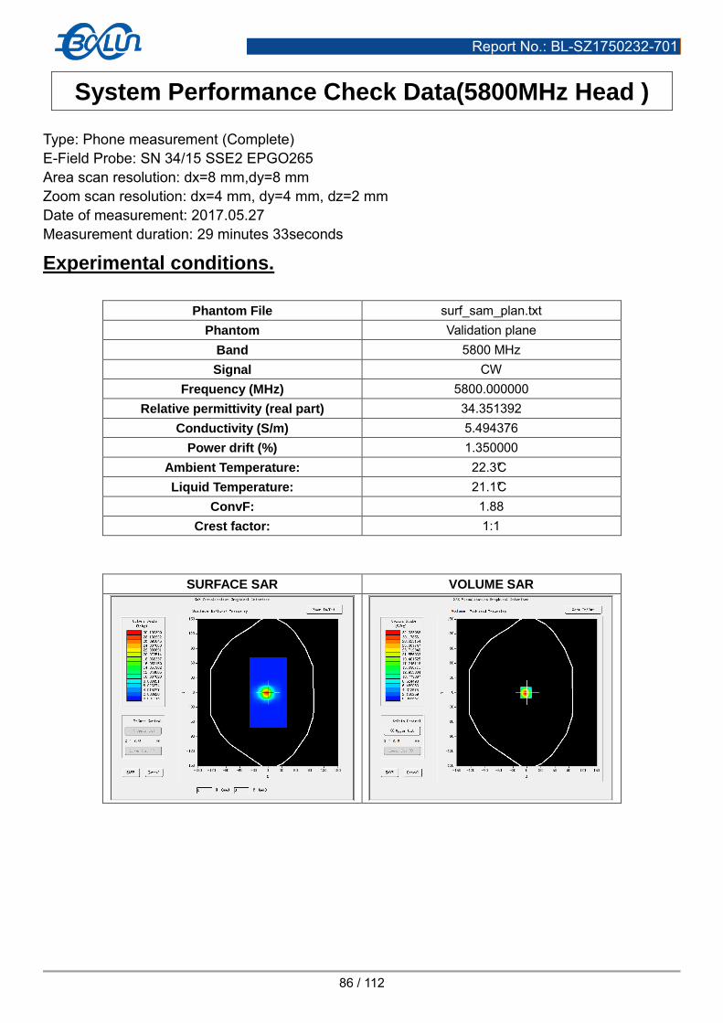
Report No.: BL-SZ1750232-701
86 / 112
System Performance Check Data(5800MHz Head ) Type: Phone measurement (Complete) E-Field Probe: SN 34/15 SSE2 EPGO265 Area scan resolution: dx=8 mm,dy=8 mm Zoom scan resolution: dx=4 mm, dy=4 mm, dz=2 mm Date of measurement: 2017.05.27 Measurement duration: 29 minutes 33seconds
Experimental conditions.
Phantom File surf_sam_plan.txt Phantom Validation plane
Band 5800 MHz Signal CW
Frequency (MHz) 5800.000000 Relative permittivity (real part) 34.351392
Conductivity (S/m) 5.494376 Power drift (%) 1.350000
Ambient Temperature: 22.3°C Liquid Temperature: 21.1°C
ConvF: 1.88 Crest factor: 1:1
SURFACE SAR VOLUME SAR

Report No.: BL-SZ1750232-701
87 / 112
Maximum location: X=-2.00, Y=0.00
SAR Peak: 51.15W/kg
SAR 10g (W/Kg) 6.162549 SAR 1g (W/Kg) 18.256235
Z Axis Scan
3D screen shot Hot spot position

Report No.: BL-SZ1750232-701
88 / 112
System Performance Check Data(5800MHz Body ) Type: Phone measurement (Complete) E-Field Probe: SN 34/15 SSE2 EPGO265 Area scan resolution: dx=8 mm,dy=8 mm Zoom scan resolution: dx=4 mm, dy=4 mm, dz=2 mm Date of measurement: 2017.05.31 Measurement duration: 29 minutes 34seconds
Experimental conditions.
Phantom File surf_sam_plan.txt Phantom Validation plane
Band 5800 MHz Signal CW
Frequency (MHz) 5800.000000 Relative permittivity (real part) 47.145306
Conductivity (S/m) 6.133132 Power drift (%) 0.950000
Ambient Temperature: 22.5°C Liquid Temperature: 21.3°C
ConvF: 1.93 Crest factor: 1:1
SURFACE SAR VOLUME SAR

Report No.: BL-SZ1750232-701
89 / 112
Maximum location: X=2.00, Y=-1.00
SAR Peak: 51.27 W/kg
SAR 10 g (W/Kg) 5.895802 SAR 1 g (W/Kg) 17.379326
Z Axis Scan
3D screen shot Hot spot position

Report No.: BL-SZ1750232-701
90 / 112
ANNEX C TEST DATA
MEAS. 1 Right Head with Cheek on Low Channel in GSM 850 mode
Test Date: 14/5/2017 Measurement duration: 12 minutes 4 seconds Signal: GSM, f=824.2 MHz, Duty Cycle: 1:8.3 Liquid Parameters: Permittivity: 41.30; Conductivity: 0.85 S/m Test condition: Ambient Temperature: 21.5°C, Liquid Temperature: 20.1°C Probe: SN 34/15 SSE2 EPGO265, ConvF: 2.04 Area Scan: sam_direct_droit2_surf10mm.txt, h= 5.00 mm Zoom Scan: 5x5x7,dx=8mm, dy=8mm, dz=5mm,Complete Maximum location: X=-56.000000, Y=-46.000000 SAR 10g (W/Kg): 0.113340 SAR 1g (W/Kg): 0.155366 Power drift (%): -4.55 3D screen shot
Z Axis Scan

Report No.: BL-SZ1750232-701
91 / 112
MEAS. 2 Body Plane with Back Side 10mm on Low Channel in GPRS 850 mode
Test Date: 11/5/2017 Measurement duration: 10 minutes 7 seconds Signal: GPRS, f=824.2 MHz, Duty Cycle: 1:4.0 Liquid Parameters: Permittivity: 55.80; Conductivity: 0.95 S/m Test condition: Ambient Temperature: 21.9°C, Liquid Temperature: 20.5°C Probe: SN 34/15 SSE2 EPGO265, ConvF: 2.12 Area Scan: sam_direct_droit2_surf10mm.txt, h= 5.00 mm Zoom Scan: 5x5x7,dx=8mm, dy=8mm, dz=5mm,Complete Maximum location: X=-10.000000, Y=28.000000 SAR 10g (W/Kg): 0.372806 SAR 1g (W/Kg): 0.509578 Power drift (%): -2.37 3D screen shot
Z Axis Scan

Report No.: BL-SZ1750232-701
92 / 112
MEAS. 3 Left Head with Cheek on Low Channel in GSM 1900 mode
Test Date: 16/5/2017 Measurement duration: 11 minutes 31 seconds Signal: GSM, f=1850.2 MHz, Duty Cycle: 1:8.3 Liquid Parameters: Permittivity: 41.05; Conductivity: 1.38 S/m Test condition: Ambient Temperature: 21.9°C, Liquid Temperature: 20.9°C Probe: SN 34/15 SSE2 EPGO265, ConvF: 2.35 Area Scan: sam_direct_droit2_surf10mm.txt, h= 5.00 mm Zoom Scan: 5x5x7,dx=8mm, dy=8mm, dz=5mm,Complete Maximum location: X=-46.000000, Y=-56.000000 SAR 10g (W/Kg): 0.081875 SAR 1g (W/Kg): 0.143411 Power drift (%): -4.73 3D screen shot
Z Axis Scan

Report No.: BL-SZ1750232-701
93 / 112
MEAS. 4 Body Plane with Bottom Edge 10mm on Low Channel in GPRS1900
mode
Test Date: 13/5/2017 Measurement duration: 12 minutes 8 seconds Signal: GPRS, f=1850.2 MHz, Duty Cycle: 1:4.0 Liquid Parameters: Permittivity: 53.20; Conductivity: 1.50 S/m Test condition: Ambient Temperature: 21.5°C, Liquid Temperature: 20.9°C Probe: SN 34/15 SSE2 EPGO265, ConvF: 2.42 Area Scan: sam_direct_droit2_surf10mm.txt, h= 5.00 mm Zoom Scan: 5x5x7,dx=8mm, dy=8mm, dz=5mm,Complete Maximum location: X=0.000000, Y=-2.000000 SAR 10g (W/Kg): 0.166298 SAR 1g (W/Kg): 0.303471 Power drift (%): -0.83 3D screen shot
Z Axis Scan

Report No.: BL-SZ1750232-701
94 / 112
MEAS. 5 Left Head with Cheek on Middle Channel in WCDMA Band 2 mode
Test Date: 16/5/2017 Measurement duration: 11 minutes 38 seconds Signal: WCDMA, f=1880.0 MHz, Duty Cycle: 1:1.0 Liquid Parameters: Permittivity: 40.31; Conductivity: 1.40 S/m Test condition: Ambient Temperature: 21.9°C, Liquid Temperature: 20.9°C Probe: SN 34/15 SSE2 EPGO265, ConvF: 2.35 Area Scan: sam_direct_droit2_surf10mm.txt, h= 5.00 mm Zoom Scan: 5x5x7,dx=8mm, dy=8mm, dz=5mm,Complete Maximum location: X=-46.000000, Y=-56.000000 SAR 10g (W/Kg): 0.201761 SAR 1g (W/Kg): 0.335020 Power drift (%): 1.86 3D screen shot
Z Axis Scan

Report No.: BL-SZ1750232-701
95 / 112
MEAS. 6 Body Plane with Bottom Edge on Middle Channel in WCDMA Band 2
mode
Test Date: 13/5/2017 Measurement duration: 13 minutes 5 seconds Signal: WCDMA, f=1880.0 MHz, Duty Cycle: 1:1.0 Liquid Parameters: Permittivity: 52.59; Conductivity: 1.52 S/m Test condition: Ambient Temperature: 21.5°C, Liquid Temperature: 20.9°C Probe: SN 34/15 SSE2 EPGO265, ConvF: 2.42 Area Scan: sam_direct_droit2_surf10mm.txt, h= 5.00 mm Zoom Scan: 5x5x7,dx=8mm, dy=8mm, dz=5mm,Complete Maximum location: X=10.000000, Y=-2.000000 SAR 10g (W/Kg): 0.275500 SAR 1g (W/Kg): 0.484028 Power drift (%): -3.06 3D screen shot
Z Axis Scan
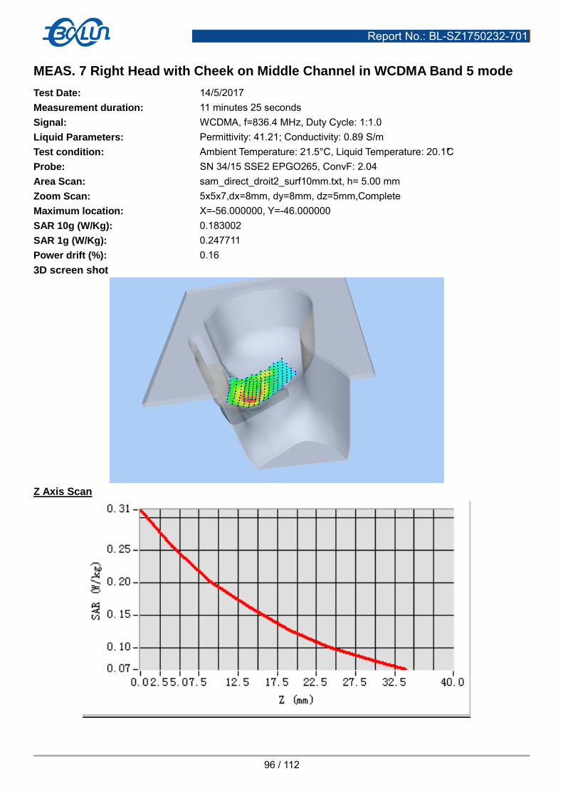
Report No.: BL-SZ1750232-701
96 / 112
MEAS. 7 Right Head with Cheek on Middle Channel in WCDMA Band 5 mode
Test Date: 14/5/2017 Measurement duration: 11 minutes 25 seconds Signal: WCDMA, f=836.4 MHz, Duty Cycle: 1:1.0 Liquid Parameters: Permittivity: 41.21; Conductivity: 0.89 S/m Test condition: Ambient Temperature: 21.5°C, Liquid Temperature: 20.1°C Probe: SN 34/15 SSE2 EPGO265, ConvF: 2.04 Area Scan: sam_direct_droit2_surf10mm.txt, h= 5.00 mm Zoom Scan: 5x5x7,dx=8mm, dy=8mm, dz=5mm,Complete Maximum location: X=-56.000000, Y=-46.000000 SAR 10g (W/Kg): 0.183002 SAR 1g (W/Kg): 0.247711 Power drift (%): 0.16 3D screen shot
Z Axis Scan

Report No.: BL-SZ1750232-701
97 / 112
MEAS. 8 Body Plane with Back Side 10mm on Middle Channel in WCDMA
Band 5 mode
Test Date: 11/5/2017 Measurement duration: 9 minutes 56 seconds Signal: WCDMA, f=836.4 MHz, Duty Cycle: 1:1.0 Liquid Parameters: Permittivity: 54.27; Conductivity: 0.98 S/m Test condition: Ambient Temperature: 21.9°C, Liquid Temperature: 20.5°C Probe: SN 34/15 SSE2 EPGO265, ConvF: 2.12 Area Scan: sam_direct_droit2_surf10mm.txt, h= 5.00 mm Zoom Scan: 5x5x7,dx=8mm, dy=8mm, dz=5mm,Complete Maximum location: X=-10.000000, Y=-32.000000 SAR 10g (W/Kg): 0.375438 SAR 1g (W/Kg): 0.498493 Power drift (%): -0.69 3D screen shot
Z Axis Scan

Report No.: BL-SZ1750232-701
98 / 112
MEAS. 9 Left Head with Cheek on Low Channel in LTE Band 2 mode
Test Date: 16/5/2017 Measurement duration: 11 minutes 37 seconds Signal: LTE, f=1860 MHz, Duty Cycle: 1:1.0 Liquid Parameters: Permittivity: 40.86; Conductivity: 1.39 S/m Test condition: Ambient Temperature: 21.9°C, Liquid Temperature: 20.9°C Probe: SN 34/15 SSE2 EPGO265, ConvF: 2.35 Area Scan: sam_direct_droit2_surf10mm.txt, h= 5.00 mm Zoom Scan: 5x5x7,dx=8mm, dy=8mm, dz=5mm,Complete Maximum location: X=-46.000000, Y=-56.000000 SAR 10g (W/Kg): 0.227378 SAR 1g (W/Kg): 0.407812 Power drift (%): -1.37 3D screen shot
Z Axis Scan

Report No.: BL-SZ1750232-701
99 / 112
MEAS. 10 Body Plane with Bottom Edge 10mm on Low Channel in LTE Band 2
mode
Test Date: 13/5/2017 Measurement duration: 11 minutes 49 seconds Signal: LTE, f=1860 MHz, Duty Cycle: 1:1.0 Liquid Parameters: Permittivity: 53.06; Conductivity: 1.51 S/m Test condition: Ambient Temperature: 21.5°C, Liquid Temperature: 20.9°C Probe: SN 34/15 SSE2 EPGO265, ConvF: 2.42 Area Scan: sam_direct_droit2_surf10mm.txt, h= 5.00 mm Zoom Scan: 5x5x7,dx=8mm, dy=8mm, dz=5mm,Complete Maximum location: X=0.000000, Y=-12.000000 SAR 10g (W/Kg): 0.389853 SAR 1g (W/Kg): 0.681791 Power drift (%): -0.18 3D screen shot
Z Axis Scan
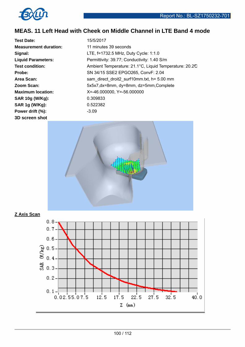
Report No.: BL-SZ1750232-701
100 / 112
MEAS. 11 Left Head with Cheek on Middle Channel in LTE Band 4 mode
Test Date: 15/5/2017 Measurement duration: 11 minutes 39 seconds Signal: LTE, f=1732.5 MHz, Duty Cycle: 1:1.0 Liquid Parameters: Permittivity: 39.77; Conductivity: 1.40 S/m Test condition: Ambient Temperature: 21.1°C, Liquid Temperature: 20.2°C Probe: SN 34/15 SSE2 EPGO265, ConvF: 2.04 Area Scan: sam_direct_droit2_surf10mm.txt, h= 5.00 mm Zoom Scan: 5x5x7,dx=8mm, dy=8mm, dz=5mm,Complete Maximum location: X=-46.000000, Y=-56.000000 SAR 10g (W/Kg): 0.309833 SAR 1g (W/Kg): 0.522382 Power drift (%): -3.09 3D screen shot
Z Axis Scan

Report No.: BL-SZ1750232-701
101 / 112
MEAS. 12 Body Plane with Bottom Edge on Middle Channel in LTE Band 4
mode
Test Date: 12/5/2017 Measurement duration: 12 minutes 4 seconds Signal: LTE, f=1732.5 MHz, Duty Cycle: 1:1.0 Liquid Parameters: Permittivity: 53.01; Conductivity: 1.46 S/m Test condition: Ambient Temperature: 21.8°C, Liquid Temperature: 20.7°C Probe: SN 34/15 SSE2 EPGO265, ConvF: 2.08 Area Scan: sam_direct_droit2_surf10mm.txt, h= 5.00 mm Zoom Scan: 5x5x7,dx=8mm, dy=8mm, dz=5mm,Complete Maximum location: X=0.000000, Y=-2.000000 SAR 10g (W/Kg): 0.368316 SAR 1g (W/Kg): 0.611051 Power drift (%): -1.48 3D screen shot
Z Axis Scan

Report No.: BL-SZ1750232-701
102 / 112
MEAS. 13 Left Head with Cheek on Middle Channel in LTE Band 7 mode
Test Date: 22/5/2017 Measurement duration: 16 minutes 25 seconds Signal: LTE, f=2535.0 MHz, Duty Cycle: 1:1.0 Liquid Parameters: Permittivity: 38.40; Conductivity: 1.88 S/m Test condition: Ambient Temperature: 21.1°C, Liquid Temperature: 20.2°C Probe: SN 34/15 SSE2 EPGO265, ConvF: 2.36 Area Scan: sam_direct_droit2_surf10mm.txt, h= 5.00 mm Zoom Scan: 7x7x7,dx=5mm, dy=5mm, dz=5mm,Complete Maximum location: X=-46.000000, Y=-56.000000 SAR 10g (W/Kg): 0.102366 SAR 1g (W/Kg): 0.173797 Power drift (%): 1.97 3D screen shot
Z Axis Scan

Report No.: BL-SZ1750232-701
103 / 112
MEAS. 14 Body Plane with Back Side on High Channel in LTE Band 7 mode
Test Date: 24/5/2017 Measurement duration: 18 minutes 46 seconds Signal: LTE, f=2560.0 MHz, Duty Cycle: 1:1.0 Liquid Parameters: Permittivity: 51.50; Conductivity: 2.10 S/m Test condition: Ambient Temperature: 22.1°C, Liquid Temperature: 20.9°C Probe: SN 34/15 SSE2 EPGO265, ConvF: 2.43 Area Scan: sam_direct_droit2_surf10mm.txt, h= 5.00 mm Zoom Scan: 7x7x7,dx=5mm, dy=5mm, dz=5mm,Complete Maximum location: X=20.000000, Y=-22.000000 SAR 10g (W/Kg): 0.539414 SAR 1g (W/Kg): 0.984648 Power drift (%): -1.03 3D screen shot
Z Axis Scan

Report No.: BL-SZ1750232-701
104 / 112
MEAS. 15 Right Head with Cheek on Middle Channel in IEEE 802.b mode
Test Date: 19/5/2017 Measurement duration: 14 minutes 14 seconds Signal: WLAN, f=2437.0 MHz, Duty Cycle: 1:1.0 Liquid Parameters: Permittivity: 40.30; Conductivity: 1.82 S/m Test condition: Ambient Temperature: 22.4°C, Liquid Temperature: 21.6°C Probe: SN 34/15 SSE2 EPGO265, ConvF: 2.47 Area Scan: sam_direct_droit2_surf10mm.txt, h= 5.00 mm Zoom Scan: 7x7x7,dx=5mm, dy=5mm, dz=5mm,Complete Maximum location: X=-26.000000, Y=14.000000 SAR 10g (W/Kg): 0.250759 SAR 1g (W/Kg): 0.467353 Power drift (%): -1.06 3D screen shot
Z Axis Scan

Report No.: BL-SZ1750232-701
105 / 112
MEAS. 16 Body Plane with Right Edge 10mm on Middle Channel in IEEE 802.b
mode
Test Date: 23/5/2017 Measurement duration: 16 minutes 52 seconds Signal: WLAN, f=2437.0 MHz, Duty Cycle: 1:1.0 Liquid Parameters: Permittivity: 52.34; Conductivity: 1.96 S/m Test condition: Ambient Temperature: 22.6°C, Liquid Temperature: 21.4°C Probe: SN 34/15 SSE2 EPGO265, ConvF: 2.55 Area Scan: sam_direct_droit2_surf10mm.txt, h= 5.00 mm Zoom Scan: 7x7x7,dx=5mm, dy=5mm, dz=5mm,Complete Maximum location: X=0.000000, Y=18.000000 SAR 10g (W/Kg): 0.117889 SAR 1g (W/Kg): 0.214411 Power drift (%): -1.04 3D screen shot
Z Axis Scan

Report No.: BL-SZ1750232-701
106 / 112
MEAS. 17 Right Head with Cheek on Channel 48 in IEEE 802.a mode
Test Date: 27/5/2017 Measurement duration: 20 minutes 1 seconds Signal: WLAN, f=5240.0 MHz, Duty Cycle: 1:1.1 Liquid Parameters: Permittivity: 36.07; Conductivity: 4.72 S/m Test condition: Ambient Temperature: 22.3°C, Liquid Temperature: 21.1°C Probe: SN 34/15 SSE2 EPGO265, ConvF: 1.81 Area Scan: sam_direct_droit2_surf10mm.txt, h= 5.00 mm Zoom Scan: 7x7x12,dx=4mm, dy=4mm, dz=2mm,Complete Maximum location: X=-16.000000, Y=24.000000 SAR 10g (W/Kg): 0.307530 SAR 1g (W/Kg): 0.851940 Power drift (%): 3.24 3D screen shot
Z Axis Scan

Report No.: BL-SZ1750232-701
107 / 112
MEAS. 18 Right Head with Cheek on Channel 100 in IEEE 802.a mode
Test Date: 27/5/2017 Measurement duration: 19 minutes 47 seconds Signal: WLAN, f=5500.0 MHz, Duty Cycle: 1:1.1 Liquid Parameters: Permittivity: 35.36; Conductivity: 5.15 S/m Test condition: Ambient Temperature: 22.3°C, Liquid Temperature: 21.1°C Probe: SN 34/15 SSE2 EPGO265, ConvF: 2.08 Area Scan: sam_direct_droit2_surf10mm.txt, h= 5.00 mm Zoom Scan: 7x7x12,dx=4mm, dy=4mm, dz=2mm,Complete Maximum location: X=-26.000000, Y=24.000000 SAR 10g (W/Kg): 0.309697 SAR 1g (W/Kg): 0.854008 Power drift (%): -1.39 3D screen shot
Z Axis Scan

Report No.: BL-SZ1750232-701
108 / 112
MEAS. 19 Right Head with Cheek on Channel 149 in IEEE 802.a mode
Test Date: 27/5/2017 Measurement duration: 19 minutes 57 seconds Signal: WLAN, f=5745.0 MHz, Duty Cycle: 1:1.1 Liquid Parameters: Permittivity: 34.42; Conductivity: 5.42 S/m Test condition: Ambient Temperature: 22.3°C, Liquid Temperature: 21.1°C Probe: SN 34/15 SSE2 EPGO265, ConvF: 1.88 Area Scan: sam_direct_droit2_surf10mm.txt, h= 5.00 mm Zoom Scan: 7x7x12,dx=4mm, dy=4mm, dz=2mm,Complete Maximum location: X=-26.000000, Y=24.000000 SAR 10g (W/Kg): 0.277435 SAR 1g (W/Kg): 0.773268 Power drift (%): -3.53 3D screen shot
Z Axis Scan

Report No.: BL-SZ1750232-701
109 / 112
MEAS. 20 Body Plane with Right Edge 10mm on Channel 44 in IEEE 802.a
mode
Test Date: 31/5/2017 Measurement duration: 29 minutes 45 seconds Signal: WLAN, f=5220.0 MHz, Duty Cycle: 1:1.1 Liquid Parameters: Permittivity: 48.51; Conductivity: 5.30 S/m Test condition: Ambient Temperature: 22.5°C, Liquid Temperature: 21.3°C Probe: SN 34/15 SSE2 EPGO265, ConvF: 1.85 Area Scan: sam_direct_droit2_surf10mm.txt, h= 5.00 mm Zoom Scan: 7x7x12,dx=4mm, dy=4mm, dz=2mm,Complete Maximum location: X=10.000000, Y=-2.000000 SAR 10g (W/Kg): 0.203610 SAR 1g (W/Kg): 0.373711 Power drift (%): -4.50 3D screen shot
Z Axis Scan
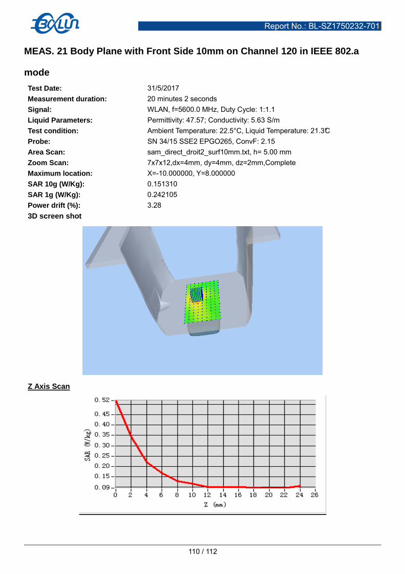
Report No.: BL-SZ1750232-701
110 / 112
MEAS. 21 Body Plane with Front Side 10mm on Channel 120 in IEEE 802.a
mode
Test Date: 31/5/2017 Measurement duration: 20 minutes 2 seconds Signal: WLAN, f=5600.0 MHz, Duty Cycle: 1:1.1 Liquid Parameters: Permittivity: 47.57; Conductivity: 5.63 S/m Test condition: Ambient Temperature: 22.5°C, Liquid Temperature: 21.3°C Probe: SN 34/15 SSE2 EPGO265, ConvF: 2.15 Area Scan: sam_direct_droit2_surf10mm.txt, h= 5.00 mm Zoom Scan: 7x7x12,dx=4mm, dy=4mm, dz=2mm,Complete Maximum location: X=-10.000000, Y=8.000000 SAR 10g (W/Kg): 0.151310 SAR 1g (W/Kg): 0.242105 Power drift (%): 3.28 3D screen shot
Z Axis Scan

Report No.: BL-SZ1750232-701
111 / 112
MEAS. 22 Body Plane with Right Edge 10mm on Channel 157 in IEEE 802.a
mode
Test Date: 31/5/2017 Measurement duration: 26 minutes 52 seconds Signal: WLAN, f=5785.0 MHz, Duty Cycle: 1:1.1 Liquid Parameters: Permittivity: 47.31; Conductivity: 6.02 S/m Test condition: Ambient Temperature: 22.5°C, Liquid Temperature: 21.3°C Probe: SN 34/15 SSE2 EPGO265, ConvF: 1.93 Area Scan: sam_direct_droit2_surf10mm.txt, h= 5.00 mm Zoom Scan: 7x7x12,dx=4mm, dy=4mm, dz=2mm,Complete Maximum location: X=0.000000, Y=8.000000 SAR 10g (W/Kg): 0.180989 SAR 1g (W/Kg): 0.309892 Power drift (%): -2.57 3D screen shot
Z Axis Scan

Report No.: BL-SZ1750232-701
112 / 112
ANNEX D EUT EXTERNAL PHOTOS
Please refer the document “BL-SZ1750232-AW.pdf”.
ANNEX E SAR TEST SETUP PHOTOS
Please refer the document “BL-SZ1750232-AS.pdf”.
ANNEX F CALIBRATION REPORT
Please refer the document “CALIBRATION REPORT.pdf”.
--END OF REPORT--