Embed Size (px)
Citation preview
FCC Test Report Report No. : FR391736AN
SPORTON INTERNATIONAL INC. Page No. : 1 of 55
TEL : 886-3-3273456 Report Version : Rev. 01
FAX : 886-3-3270973
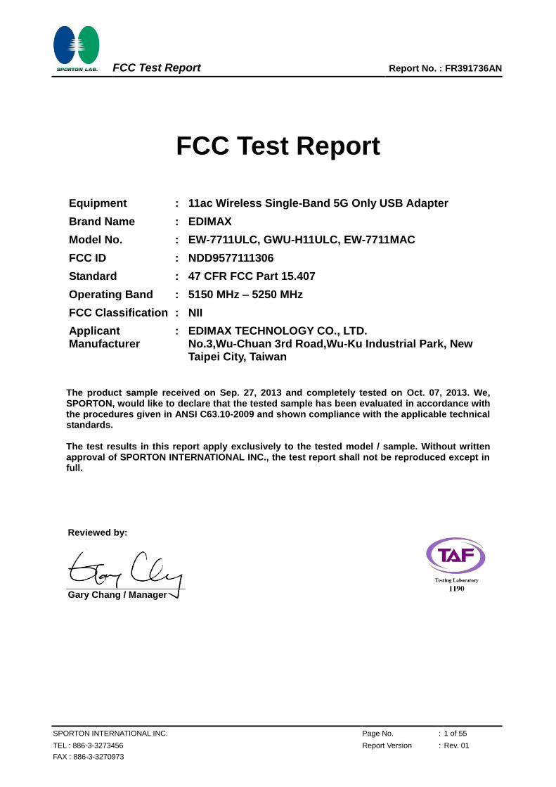
FCC Test Report
Equipment : 11ac Wireless Single-Band 5G Only USB Adapter
Brand Name : EDIMAX
Model No. : EW-7711ULC, GWU-H11ULC, EW-7711MAC
FCC ID : NDD9577111306
Standard : 47 CFR FCC Part 15.407
Operating Band : 5150 MHz – 5250 MHz
FCC Classification : NII
Applicant Manufacturer
: EDIMAX TECHNOLOGY CO., LTD. No.3,Wu-Chuan 3rd Road,Wu-Ku Industrial Park, New Taipei City, Taiwan
The product sample received on Sep. 27, 2013 and completely tested on Oct. 07, 2013. We, SPORTON, would like to declare that the tested sample has been evaluated in accordance with the procedures given in ANSI C63.10-2009 and shown compliance with the applicable technical standards. The test results in this report apply exclusively to the tested model / sample. Without written approval of SPORTON INTERNATIONAL INC., the test report shall not be reproduced except in full. Reviewed by:
Gary Chang / Manager
FCC Test Report Report No. : FR391736AN
SPORTON INTERNATIONAL INC. Page No. : 2 of 55
TEL : 886-3-3273456 Report Version : Rev. 01
FAX : 886-3-3270973
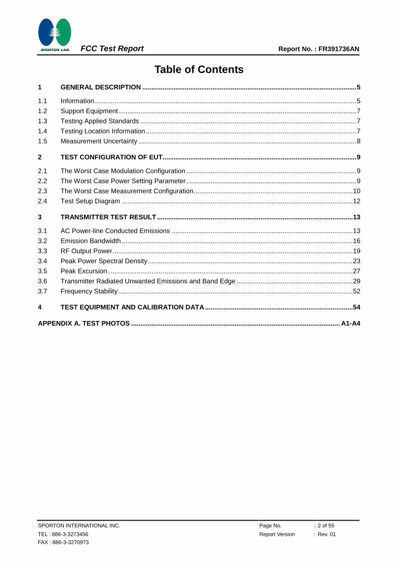
Table of Contents 1 GENERAL DESCRIPTION .................................................................................................................... 5
1.1 Information .............................................................................................................................................. 5 1.2 Support Equipment ................................................................................................................................. 7 1.3 Testing Applied Standards ..................................................................................................................... 7 1.4 Testing Location Information .................................................................................................................. 7 1.5 Measurement Uncertainty ...................................................................................................................... 8
2 TEST CONFIGURATION OF EUT......................................................................................................... 9
2.1 The Worst Case Modulation Configuration ............................................................................................ 9 2.2 The Worst Case Power Setting Parameter ............................................................................................ 9 2.3 The Worst Case Measurement Configuration ...................................................................................... 10 2.4 Test Setup Diagram ............................................................................................................................. 12
3 TRANSMITTER TEST RESULT .......................................................................................................... 13
3.1 AC Power-line Conducted Emissions .................................................................................................. 13 3.2 Emission Bandwidth ............................................................................................................................. 16 3.3 RF Output Power .................................................................................................................................. 19 3.4 Peak Power Spectral Density ............................................................................................................... 23
3.5 Peak Excursion..................................................................................................................................... 27 3.6 Transmitter Radiated Unwanted Emissions and Band Edge ............................................................... 29 3.7 Frequency Stability ............................................................................................................................... 52
4 TEST EQUIPMENT AND CALIBRATION DATA ................................................................................ 54
APPENDIX A. TEST PHOTOS ................................................................................................................. A1-A4
FCC Test Report Report No. : FR391736AN
SPORTON INTERNATIONAL INC. Page No. : 3 of 55
TEL : 886-3-3273456 Report Version : Rev. 01
FAX : 886-3-3270973
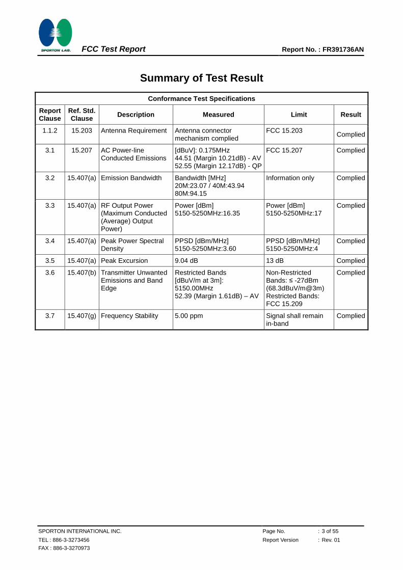
Summary of Test Result
Conformance Test Specifications
Report Clause
Ref. Std. Clause
Description Measured Limit Result
1.1.2 15.203 Antenna Requirement Antenna connector mechanism complied
FCC 15.203 Complied
3.1 15.207 AC Power-line Conducted Emissions
[dBuV]: 0.175MHz 44.51 (Margin 10.21dB) - AV 52.55 (Margin 12.17dB) - QP
FCC 15.207 Complied
3.2 15.407(a) Emission Bandwidth Bandwidth [MHz] 20M:23.07 / 40M:43.94 80M:94.15
Information only Complied
3.3 15.407(a) RF Output Power (Maximum Conducted (Average) Output Power)
Power [dBm] 5150-5250MHz:16.35
Power [dBm] 5150-5250MHz:17
Complied
3.4 15.407(a) Peak Power Spectral Density
PPSD [dBm/MHz] 5150-5250MHz:3.60
PPSD [dBm/MHz] 5150-5250MHz:4
Complied
3.5 15.407(a) Peak Excursion 9.04 dB 13 dB Complied
3.6 15.407(b) Transmitter Unwanted Emissions and Band Edge
Restricted Bands [dBuV/m at 3m]: 5150.00MHz 52.39 (Margin 1.61dB) – AV
Non-Restricted Bands: ≤ -27dBm (68.3dBuV/m@3m) Restricted Bands: FCC 15.209
Complied
3.7 15.407(g) Frequency Stability 5.00 ppm Signal shall remain in-band
Complied
FCC Test Report Report No. : FR391736AN
SPORTON INTERNATIONAL INC. Page No. : 4 of 55
TEL : 886-3-3273456 Report Version : Rev. 01
FAX : 886-3-3270973
Revision History
Report No. Version Description Issued Date
FR391736AN Rev. 01 Initial issue of report Oct. 30, 2013
FCC Test Report Report No. : FR391736AN
SPORTON INTERNATIONAL INC. Page No. : 5 of 55
TEL : 886-3-3273456 Report Version : Rev. 01
FAX : 886-3-3270973
1 General Description
1.1 Information
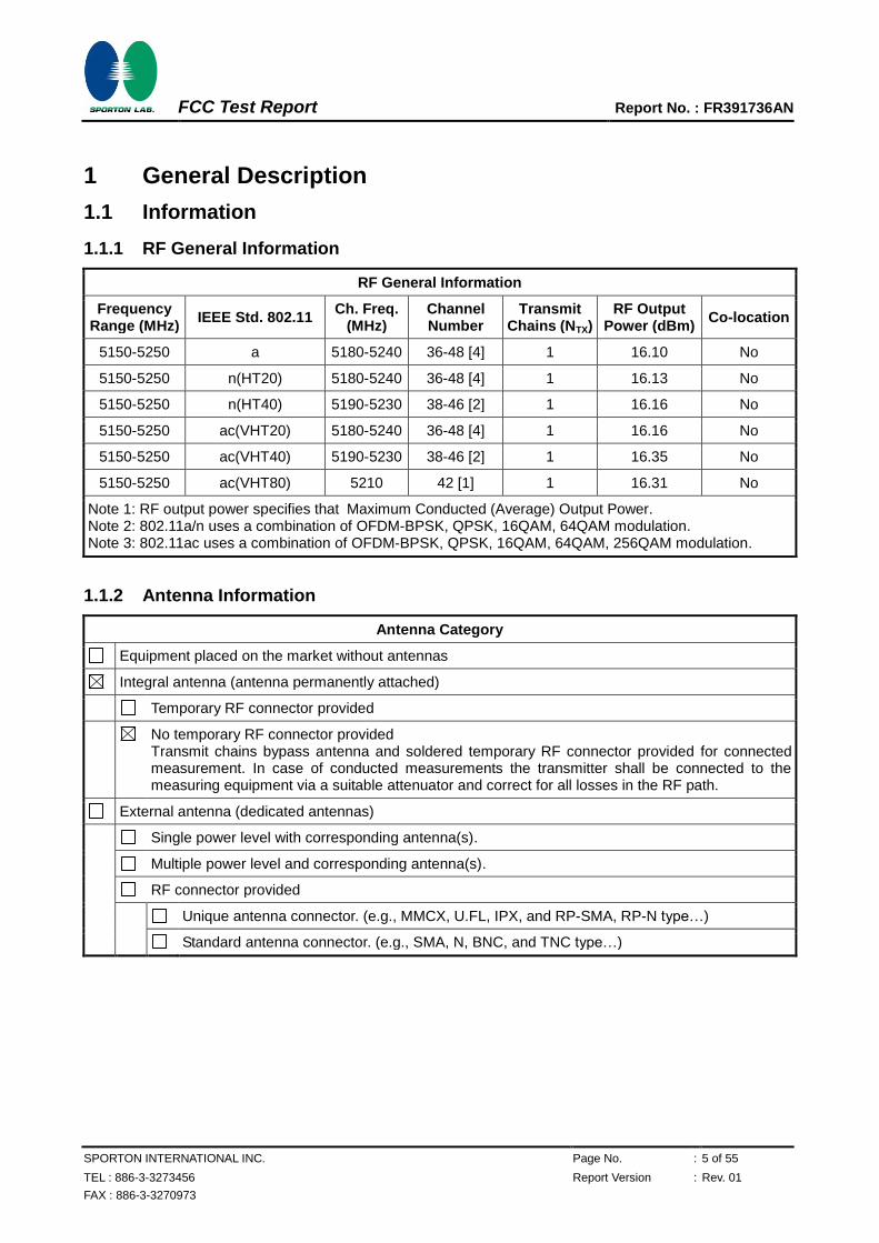
1.1.1 RF General Information
RF General Information
Frequency Range (MHz)
IEEE Std. 802.11 Ch. Freq.
(MHz) Channel Number
Transmit Chains (NTX)
RF Output Power (dBm)
Co-location
5150-5250 a 5180-5240 36-48 [4] 1 16.10 No
5150-5250 n(HT20) 5180-5240 36-48 [4] 1 16.13 No
5150-5250 n(HT40) 5190-5230 38-46 [2] 1 16.16 No
5150-5250 ac(VHT20) 5180-5240 36-48 [4] 1 16.16 No
5150-5250 ac(VHT40) 5190-5230 38-46 [2] 1 16.35 No
5150-5250 ac(VHT80) 5210 42 [1] 1 16.31 No
Note 1: RF output power specifies that Maximum Conducted (Average) Output Power. Note 2: 802.11a/n uses a combination of OFDM-BPSK, QPSK, 16QAM, 64QAM modulation. Note 3: 802.11ac uses a combination of OFDM-BPSK, QPSK, 16QAM, 64QAM, 256QAM modulation.
1.1.2 Antenna Information
Antenna Category
Equipment placed on the market without antennas
Integral antenna (antenna permanently attached)
Temporary RF connector provided
No temporary RF connector provided Transmit chains bypass antenna and soldered temporary RF connector provided for connected measurement. In case of conducted measurements the transmitter shall be connected to the measuring equipment via a suitable attenuator and correct for all losses in the RF path.
External antenna (dedicated antennas)
Single power level with corresponding antenna(s).
Multiple power level and corresponding antenna(s).
RF connector provided
Unique antenna connector. (e.g., MMCX, U.FL, IPX, and RP-SMA, RP-N type…)
Standard antenna connector. (e.g., SMA, N, BNC, and TNC type…)
FCC Test Report Report No. : FR391736AN
SPORTON INTERNATIONAL INC. Page No. : 6 of 55
TEL : 886-3-3273456 Report Version : Rev. 01
FAX : 886-3-3270973
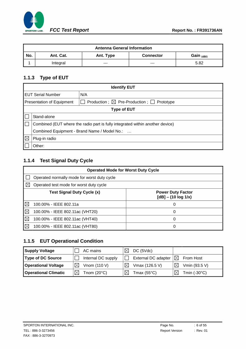
Antenna General Information
No. Ant. Cat. Ant. Type Connector Gain (dBi)
1 Integral --- --- 5.82
1.1.3 Type of EUT
Identify EUT
EUT Serial Number N/A
Presentation of Equipment Production ; Pre-Production ; Prototype
Type of EUT
Stand-alone
Combined (EUT where the radio part is fully integrated within another device)
Combined Equipment - Brand Name / Model No.: …
Plug-in radio
Other:
1.1.4 Test Signal Duty Cycle
Operated Mode for Worst Duty Cycle
Operated normally mode for worst duty cycle
Operated test mode for worst duty cycle
Test Signal Duty Cycle (x) Power Duty Factor [dB] – (10 log 1/x)
100.00% - IEEE 802.11a 0
100.00% - IEEE 802.11ac (VHT20) 0
100.00% - IEEE 802.11ac (VHT40) 0
100.00% - IEEE 802.11ac (VHT80) 0
Note 1: RF Output Power Plots w/o Duty Factor Note 1: Power Density Plots w/o Duty Factor
1.1.5 EUT Operational Condition
Supply Voltage AC mains DC (5Vdc)
Type of DC Source Internal DC supply External DC adapter From Host
Operational Voltage Vnom (110 V) Vmax (126.5 V) Vmin (93.5 V)
Operational Climatic Tnom (20°C) Tmax (55°C) Tmin (-30°C)
FCC Test Report Report No. : FR391736AN
SPORTON INTERNATIONAL INC. Page No. : 7 of 55
TEL : 886-3-3273456 Report Version : Rev. 01
FAX : 886-3-3270973
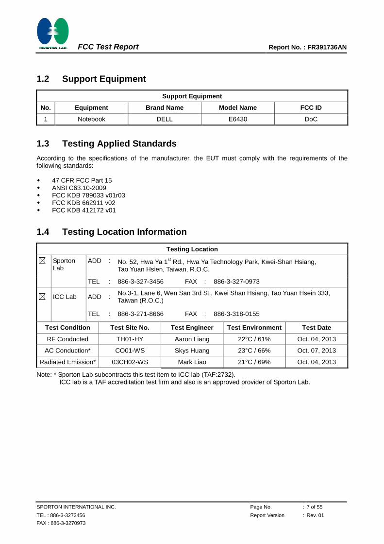
1.2 Support Equipment
Support Equipment
No. Equipment Brand Name Model Name FCC ID
1 Notebook DELL E6430 DoC
1.3 Testing Applied Standards
According to the specifications of the manufacturer, the EUT must comply with the requirements of the following standards: 47 CFR FCC Part 15 ANSI C63.10-2009 FCC KDB 789033 v01r03 FCC KDB 662911 v02 FCC KDB 412172 v01
1.4 Testing Location Information
Testing Location
Sporton Lab
ADD : No. 52, Hwa Ya 1st Rd., Hwa Ya Technology Park, Kwei-Shan Hsiang,
Tao Yuan Hsien, Taiwan, R.O.C.
TEL : 886-3-327-3456 FAX : 886-3-327-0973
ICC Lab ADD : No.3-1, Lane 6, Wen San 3rd St., Kwei Shan Hsiang, Tao Yuan Hsein 333, Taiwan (R.O.C.)
TEL : 886-3-271-8666 FAX : 886-3-318-0155
Test Condition Test Site No. Test Engineer Test Environment Test Date
RF Conducted TH01-HY Aaron Liang 22°C / 61% Oct. 04, 2013
AC Conduction* CO01-WS Skys Huang 23°C / 66% Oct. 07, 2013
Radiated Emission* 03CH02-WS Mark Liao 21°C / 69% Oct. 04, 2013
Note: * Sporton Lab subcontracts this test item to ICC lab (TAF:2732). ICC lab is a TAF accreditation test firm and also is an approved provider of Sporton Lab.
FCC Test Report Report No. : FR391736AN
SPORTON INTERNATIONAL INC. Page No. : 8 of 55
TEL : 886-3-3273456 Report Version : Rev. 01
FAX : 886-3-3270973
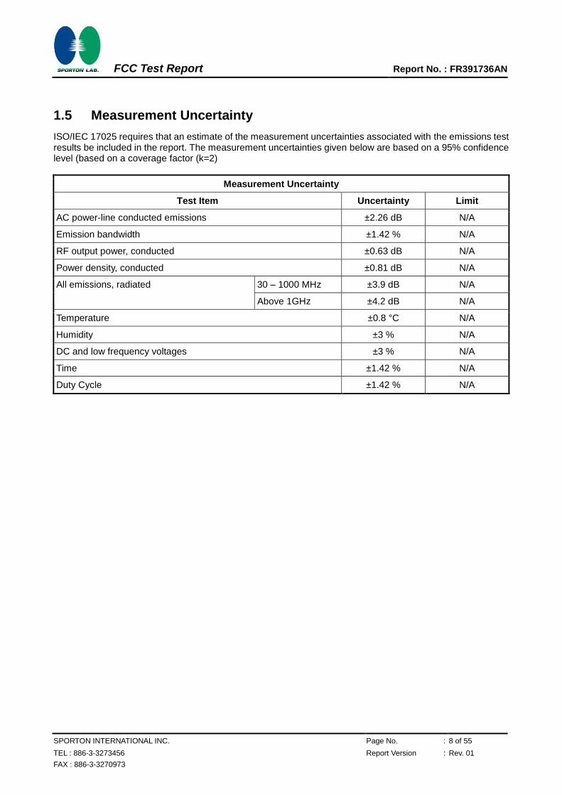
1.5 Measurement Uncertainty
ISO/IEC 17025 requires that an estimate of the measurement uncertainties associated with the emissions test results be included in the report. The measurement uncertainties given below are based on a 95% confidence level (based on a coverage factor (k=2)
Measurement Uncertainty
Test Item Uncertainty Limit
AC power-line conducted emissions ±2.26 dB N/A
Emission bandwidth ±1.42 % N/A
RF output power, conducted ±0.63 dB N/A
Power density, conducted ±0.81 dB N/A
All emissions, radiated 30 – 1000 MHz ±3.9 dB N/A
Above 1GHz ±4.2 dB N/A
Temperature ±0.8 °C N/A
Humidity ±3 % N/A
DC and low frequency voltages ±3 % N/A
Time ±1.42 % N/A
Duty Cycle ±1.42 % N/A
FCC Test Report Report No. : FR391736AN
SPORTON INTERNATIONAL INC. Page No. : 9 of 55
TEL : 886-3-3273456 Report Version : Rev. 01
FAX : 886-3-3270973
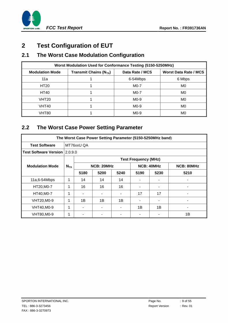
2 Test Configuration of EUT
2.1 The Worst Case Modulation Configuration
Worst Modulation Used for Conformance Testing (5150-5250MHz)
Modulation Mode Transmit Chains (NTX) Data Rate / MCS Worst Data Rate / MCS
11a 1 6-54Mbps 6 Mbps
HT20 1 M0-7 M0
HT40 1 M0-7 M0
VHT20 1 M0-9 M0
VHT40 1 M0-9 M0
VHT80 1 M0-9 M0
2.2 The Worst Case Power Setting Parameter
The Worst Case Power Setting Parameter (5150-5250MHz band)
Test Software MT76xxU QA
Test Software Version 2.0.9.0
Modulation Mode NTX
Test Frequency (MHz)
NCB: 20MHz NCB: 40MHz NCB: 80MHz
5180 5200 5240 5190 5230 5210
11a,6-54Mbps 1 14 14 14 - - -
HT20,M0-7 1 16 16 16 - - -
HT40,M0-7 1 - - - 17 17 -
VHT20,M0-9 1 1B 1B 1B - - -
VHT40,M0-9 1 - - - 1B 1B -
VHT80,M0-9 1 - - - - - 1B
FCC Test Report Report No. : FR391736AN
SPORTON INTERNATIONAL INC. Page No. : 10 of 55
TEL : 886-3-3273456 Report Version : Rev. 01
FAX : 886-3-3270973
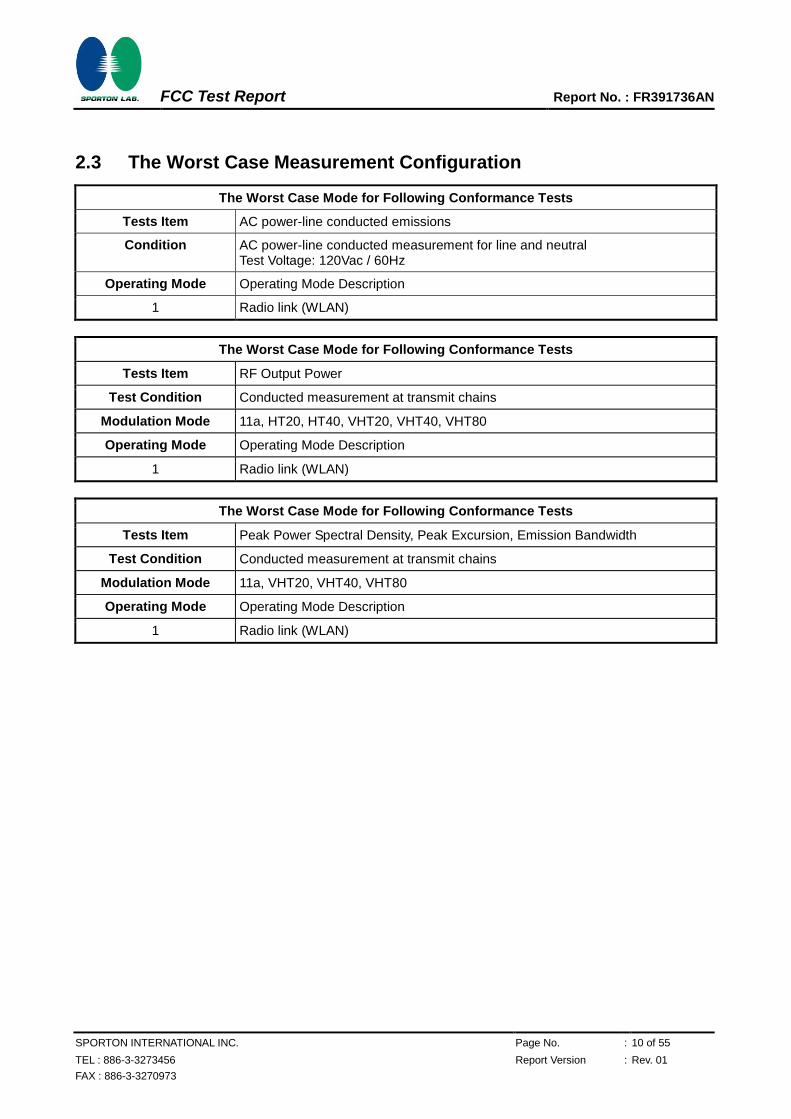
2.3 The Worst Case Measurement Configuration
The Worst Case Mode for Following Conformance Tests
Tests Item AC power-line conducted emissions
Condition AC power-line conducted measurement for line and neutral Test Voltage: 120Vac / 60Hz
Operating Mode Operating Mode Description
1 Radio link (WLAN)
The Worst Case Mode for Following Conformance Tests
Tests Item RF Output Power
Test Condition Conducted measurement at transmit chains
Modulation Mode 11a, HT20, HT40, VHT20, VHT40, VHT80
Operating Mode Operating Mode Description
1 Radio link (WLAN)
The Worst Case Mode for Following Conformance Tests
Tests Item Peak Power Spectral Density, Peak Excursion, Emission Bandwidth
Test Condition Conducted measurement at transmit chains
Modulation Mode 11a, VHT20, VHT40, VHT80
Operating Mode Operating Mode Description
1 Radio link (WLAN)
FCC Test Report Report No. : FR391736AN
SPORTON INTERNATIONAL INC. Page No. : 11 of 55
TEL : 886-3-3273456 Report Version : Rev. 01
FAX : 886-3-3270973
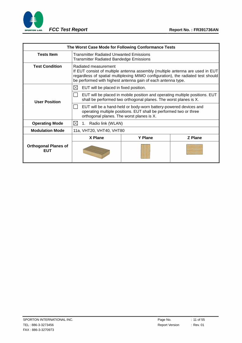
The Worst Case Mode for Following Conformance Tests
Tests Item Transmitter Radiated Unwanted Emissions Transmitter Radiated Bandedge Emissions
Test Condition Radiated measurement If EUT consist of multiple antenna assembly (multiple antenna are used in EUT regardless of spatial multiplexing MIMO configuration), the radiated test should be performed with highest antenna gain of each antenna type.
User Position
EUT will be placed in fixed position.
EUT will be placed in mobile position and operating multiple positions. EUT shall be performed two orthogonal planes. The worst planes is X.
EUT will be a hand-held or body-worn battery-powered devices and operating multiple positions. EUT shall be performed two or three orthogonal planes. The worst planes is X.
Operating Mode 1. Radio link (WLAN)
Modulation Mode 11a, VHT20, VHT40, VHT80
Orthogonal Planes of EUT
X Plane Y Plane Z Plane
FCC Test Report Report No. : FR391736AN
SPORTON INTERNATIONAL INC. Page No. : 12 of 55
TEL : 886-3-3273456 Report Version : Rev. 01
FAX : 886-3-3270973
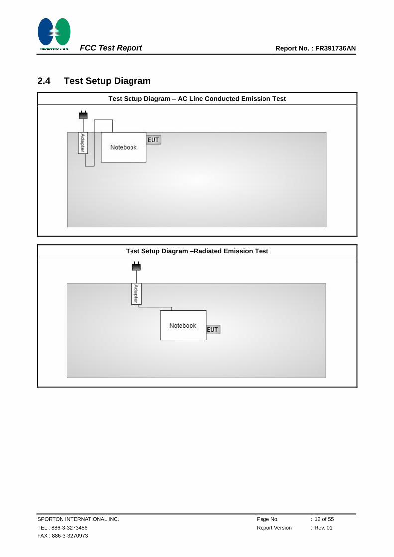
2.4 Test Setup Diagram
Test Setup Diagram – AC Line Conducted Emission Test
Test Setup Diagram –Radiated Emission Test
FCC Test Report Report No. : FR391736AN
SPORTON INTERNATIONAL INC. Page No. : 13 of 55
TEL : 886-3-3273456 Report Version : Rev. 01
FAX : 886-3-3270973
3 Transmitter Test Result
3.1 AC Power-line Conducted Emissions
3.1.1 AC Power-line Conducted Emissions Limit
AC Power-line Conducted Emissions Limit
Frequency Emission (MHz) Quasi-Peak Average
0.15-0.5 66 - 56 * 56 - 46 *
0.5-5 56 46
5-30 60 50
Note 1: * Decreases with the logarithm of the frequency.
3.1.2 Measuring Instruments
Refer a test equipment and calibration data table in this test report.
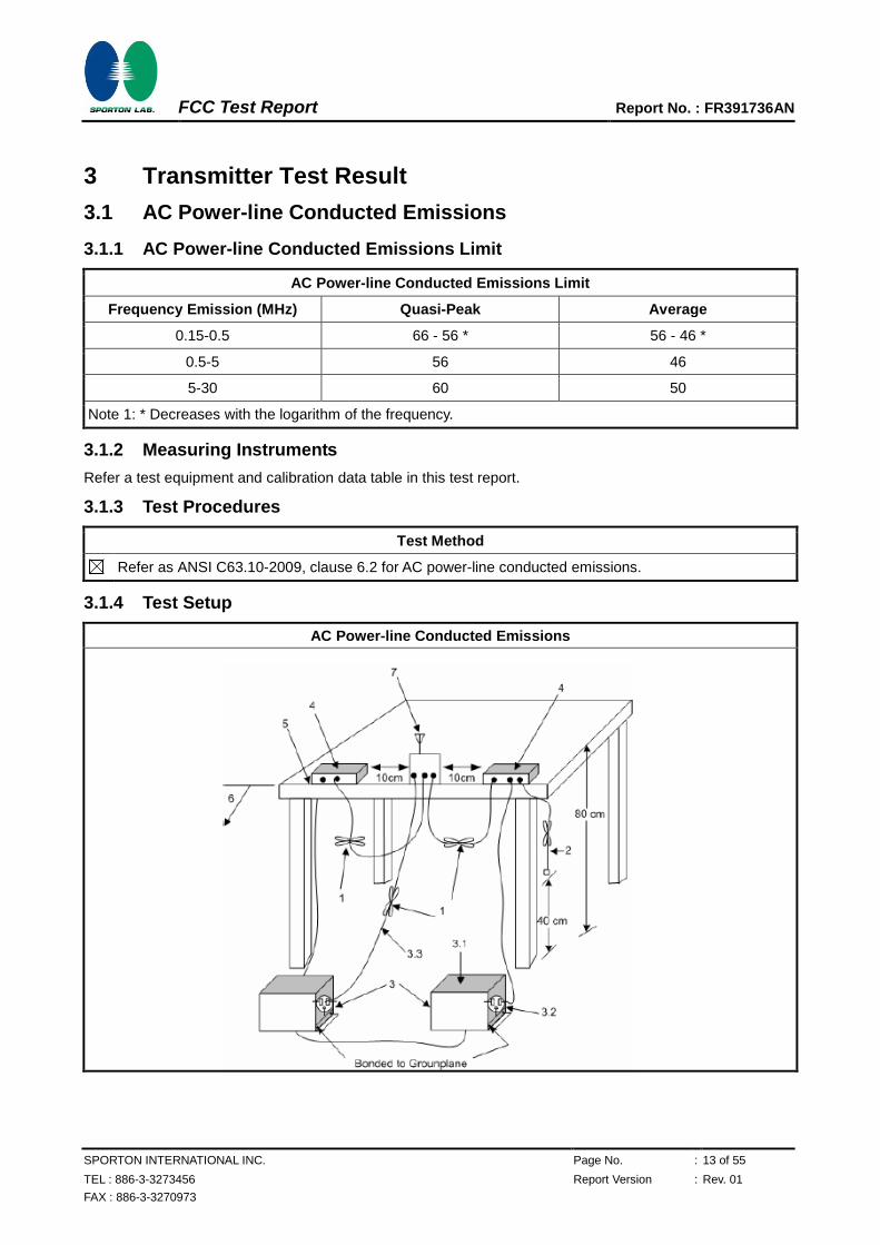
3.1.3 Test Procedures
Test Method
Refer as ANSI C63.10-2009, clause 6.2 for AC power-line conducted emissions.
3.1.4 Test Setup
AC Power-line Conducted Emissions
FCC Test Report Report No. : FR391736AN
SPORTON INTERNATIONAL INC. Page No. : 14 of 55
TEL : 886-3-3273456 Report Version : Rev. 01
FAX : 886-3-3270973
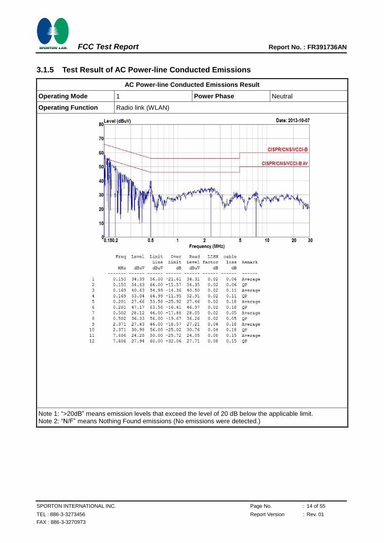
3.1.5 Test Result of AC Power-line Conducted Emissions
AC Power-line Conducted Emissions Result
Operating Mode 1 Power Phase Neutral
Operating Function Radio link (WLAN)
Note 1: “>20dB” means emission levels that exceed the level of 20 dB below the applicable limit. Note 2: “N/F” means Nothing Found emissions (No emissions were detected.)
FCC Test Report Report No. : FR391736AN
SPORTON INTERNATIONAL INC. Page No. : 15 of 55
TEL : 886-3-3273456 Report Version : Rev. 01
FAX : 886-3-3270973
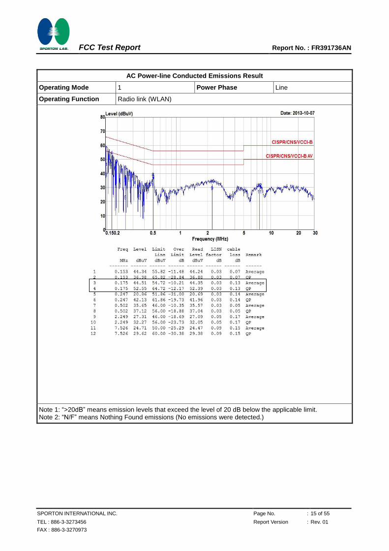
AC Power-line Conducted Emissions Result
Operating Mode 1 Power Phase Line
Operating Function Radio link (WLAN)
Note 1: “>20dB” means emission levels that exceed the level of 20 dB below the applicable limit. Note 2: “N/F” means Nothing Found emissions (No emissions were detected.)
FCC Test Report Report No. : FR391736AN
SPORTON INTERNATIONAL INC. Page No. : 16 of 55
TEL : 886-3-3273456 Report Version : Rev. 01
FAX : 886-3-3270973
3.2 Emission Bandwidth
3.2.1 Emission Bandwidth (EBW) Limit
Emission Bandwidth (EBW) Limit
UNII Devices
For the 5.15-5.25 GHz band, the maximum conducted output power shall not exceed the lesser of 50 mW or 4 dBm + 10 log B, where B is the 26 dB emission bandwidth in MHz.
For the 5.25-5.35 GHz band, the maximum conducted output power shall not exceed the lesser of 250 mW or 11 dBm + 10 log B, where B is the 26 dB emission bandwidth in MHz.
For the 5.47-5.725 GHz band, the maximum conducted output power shall not exceed the lesser of 250 mW or 11 dBm + 10 log B, where B is the 26 dB emission bandwidth in MHz.
For the 5.725-5.825 GHz band, the maximum conducted output power shall not exceed the lesser of 1 W or 17 dBm + 10 log B, where B is the 26 dB emission bandwidth in MHz
LE-LAN Devices
For the band 5.15-5.25 GHz, the maximum e.i.r.p. shall not exceed 200 mW or 10 + 10 log B, dBm, whichever power is less. B is the 99% emission bandwidth in MHz.
For the 5.25-5.35 GHz band, the maximum e.i.r.p. shall not exceed 1.0 W or 17 + 10 log B, dBm, whichever power is less. B is the 99% emission bandwidth in MHz
For the 5.47-5.6 GHz band and 5.65-5.725 GHz band, the maximum e.i.r.p. shall not exceed 1.0 W or 17 + 10 log B, dBm, whichever power is less. B is the 99% emission bandwidth in MHz
For the 5.725-5.825 GHz band, the maximum e.i.r.p. shall not exceed 4.0 W or 23 + 10 log B, dBm, whichever power is less. B is the 99% emission bandwidth in MHz.
3.2.2 Measuring Instruments
Refer a test equipment and calibration data table in this test report.
3.2.3 Test Procedures
Test Method
For the emission bandwidth shall be measured using one of the options below:
Refer as FCC KDB 789033 v01r03, clause C for EBW and clause D for OBW measurement.
Refer as ANSI C63.10, clause 6.9.1 for occupied bandwidth testing.
Refer as IC RSS-Gen, clause 4.6 for bandwidth testing.
For conducted measurement.
The EUT supports single transmit chain and measurements performed on this transmit chain.
The EUT supports diversity transmitting and the results on transmit chain port 1 is the worst case.
The EUT supports multiple transmit chains using options given below:
Option 1: Multiple transmit chains measurements need to be performed on one of the active transmit chains (antenna outputs). All measurement had be performed on transmit chains 1.
Option 2: Multiple transmit chains measurements need to be performed on each transmit chains individually (antenna outputs). All measurement had be performed on all transmit chains.
FCC Test Report Report No. : FR391736AN
SPORTON INTERNATIONAL INC. Page No. : 17 of 55
TEL : 886-3-3273456 Report Version : Rev. 01
FAX : 886-3-3270973
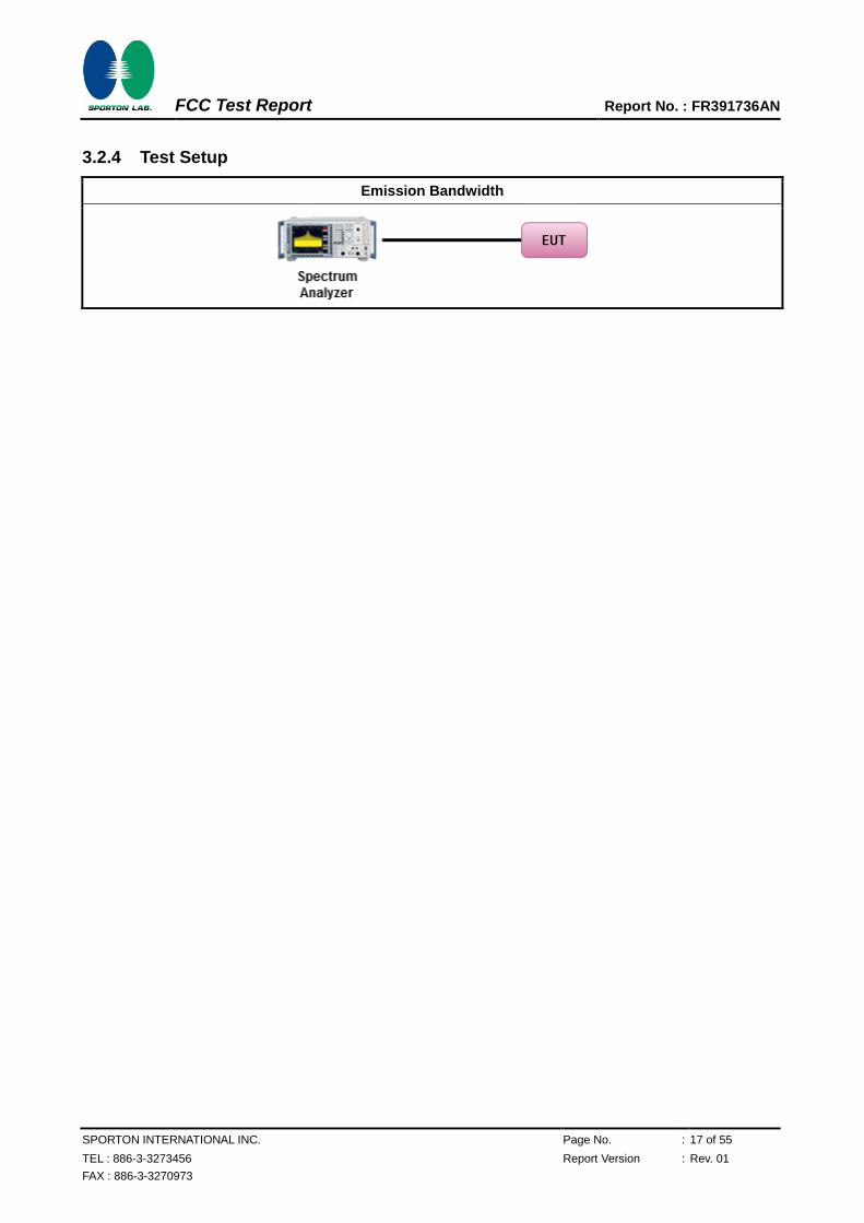
3.2.4 Test Setup
Emission Bandwidth
FCC Test Report Report No. : FR391736AN
SPORTON INTERNATIONAL INC. Page No. : 18 of 55
TEL : 886-3-3273456 Report Version : Rev. 01
FAX : 886-3-3270973
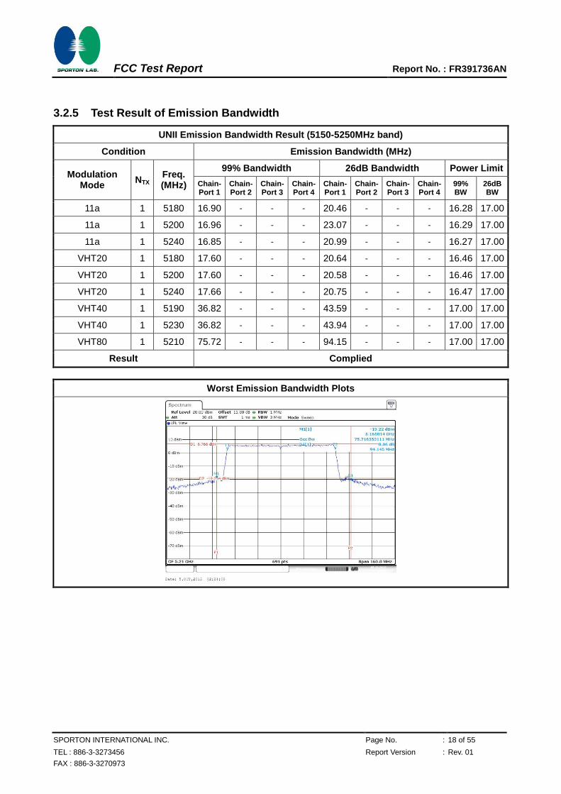
3.2.5 Test Result of Emission Bandwidth
UNII Emission Bandwidth Result (5150-5250MHz band)
Condition Emission Bandwidth (MHz)
Modulation Mode
NTX Freq. (MHz)
99% Bandwidth 26dB Bandwidth Power Limit
Chain- Port 1
Chain- Port 2
Chain- Port 3
Chain- Port 4
Chain- Port 1
Chain- Port 2
Chain- Port 3
Chain- Port 4
99% BW
26dB BW
11a 1 5180 16.90 - - - 20.46 - - - 16.28 17.00
11a 1 5200 16.96 - - - 23.07 - - - 16.29 17.00
11a 1 5240 16.85 - - - 20.99 - - - 16.27 17.00
VHT20 1 5180 17.60 - - - 20.64 - - - 16.46 17.00
VHT20 1 5200 17.60 - - - 20.58 - - - 16.46 17.00
VHT20 1 5240 17.66 - - - 20.75 - - - 16.47 17.00
VHT40 1 5190 36.82 - - - 43.59 - - - 17.00 17.00
VHT40 1 5230 36.82 - - - 43.94 - - - 17.00 17.00
VHT80 1 5210 75.72 - - - 94.15 - - - 17.00 17.00
Result Complied
Worst Emission Bandwidth Plots
FCC Test Report Report No. : FR391736AN
SPORTON INTERNATIONAL INC. Page No. : 19 of 55
TEL : 886-3-3273456 Report Version : Rev. 01
FAX : 886-3-3270973
3.3 RF Output Power
3.3.1 RF Output Power Limit
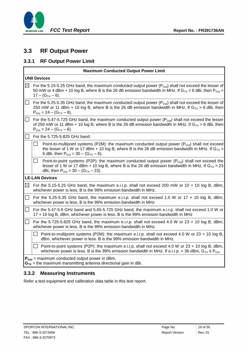
Maximum Conducted Output Power Limit
UNII Devices
For the 5.15-5.25 GHz band, the maximum conducted output power (POut) shall not exceed the lesser of 50 mW or 4 dBm + 10 log B, where B is the 26 dB emission bandwidth in MHz. If GTX > 6 dBi, then POut = 17 – (GTX – 6).
For the 5.25-5.35 GHz band, the maximum conducted output power (POut) shall not exceed the lesser of 250 mW or 11 dBm + 10 log B, where B is the 26 dB emission bandwidth in MHz. If GTX > 6 dBi, then POut = 24 – (GTX – 6).
For the 5.47-5.725 GHz band, the maximum conducted output power (POut) shall not exceed the lesser of 250 mW or 11 dBm + 10 log B, where B is the 26 dB emission bandwidth in MHz. If GTX > 6 dBi, then POut = 24 – (GTX – 6).
For the 5.725-5.825 GHz band:
Point-to-multipoint systems (P2M): the maximum conducted output power (POut) shall not exceed the lesser of 1 W or 17 dBm + 10 log B, where B is the 26 dB emission bandwidth in MHz. If GTX > 6 dBi, then POut = 30 – (GTX – 6).
Point-to-point systems (P2P): the maximum conducted output power (POut) shall not exceed the lesser of 1 W or 17 dBm + 10 log B, where B is the 26 dB emission bandwidth in MHz. If GTX > 23 dBi, then POut = 30 – (GTX – 23).
LE-LAN Devices
For the 5.15-5.25 GHz band, the maximum e.i.r.p. shall not exceed 200 mW or 10 + 10 log B, dBm, whichever power is less. B is the 99% emission bandwidth in MHz.
For the 5.25-5.35 GHz band, the maximum e.i.r.p. shall not exceed 1.0 W or 17 + 10 log B, dBm, whichever power is less. B is the 99% emission bandwidth in MHz
For the 5.47-5.6 GHz band and 5.65-5.725 GHz band, the maximum e.i.r.p. shall not exceed 1.0 W or 17 + 10 log B, dBm, whichever power is less. B is the 99% emission bandwidth in MHz
For the 5.725-5.825 GHz band, the maximum e.i.r.p. shall not exceed 4.0 W or 23 + 10 log B, dBm, whichever power is less. B is the 99% emission bandwidth in MHz.
Point-to-multipoint systems (P2M): the maximum e.i.r.p. shall not exceed 4.0 W or 23 + 10 log B, dBm, whichever power is less. B is the 99% emission bandwidth in MHz.
Point-to-point systems (P2P): the maximum e.i.r.p. shall not exceed 4.0 W or 23 + 10 log B, dBm, whichever power is less. B is the 99% emission bandwidth in MHz. If e.i.r.p. > 36 dBm, GTX ≤ POut
POut = maximum conducted output power in dBm, GTX = the maximum transmitting antenna directional gain in dBi.
3.3.2 Measuring Instruments
Refer a test equipment and calibration data table in this test report.
FCC Test Report Report No. : FR391736AN
SPORTON INTERNATIONAL INC. Page No. : 20 of 55
TEL : 886-3-3273456 Report Version : Rev. 01
FAX : 886-3-3270973
3.3.3 Test Procedures
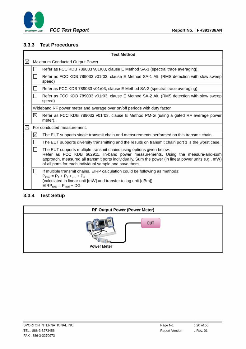
Test Method
Maximum Conducted Output Power
Refer as FCC KDB 789033 v01r03, clause E Method SA-1 (spectral trace averaging).
Refer as FCC KDB 789033 v01r03, clause E Method SA-1 Alt. (RMS detection with slow sweep speed)
Refer as FCC KDB 789033 v01r03, clause E Method SA-2 (spectral trace averaging).
Refer as FCC KDB 789033 v01r03, clause E Method SA-2 Alt. (RMS detection with slow sweep speed)
Wideband RF power meter and average over on/off periods with duty factor
Refer as FCC KDB 789033 v01r03, clause E Method PM-G (using a gated RF average power meter).
For conducted measurement.
The EUT supports single transmit chain and measurements performed on this transmit chain.
The EUT supports diversity transmitting and the results on transmit chain port 1 is the worst case.
The EUT supports multiple transmit chains using options given below: Refer as FCC KDB 662911, In-band power measurements. Using the measure-and-sum approach, measured all transmit ports individually. Sum the power (in linear power units e.g., mW) of all ports for each individual sample and save them.
If multiple transmit chains, EIRP calculation could be following as methods: Ptotal = P1 + P2 +… + Pn (calculated in linear unit [mW] and transfer to log unit [dBm]) EIRPtotal = Ptotal + DG
3.3.4 Test Setup
RF Output Power (Power Meter)
FCC Test Report Report No. : FR391736AN
SPORTON INTERNATIONAL INC. Page No. : 21 of 55
TEL : 886-3-3273456 Report Version : Rev. 01
FAX : 886-3-3270973
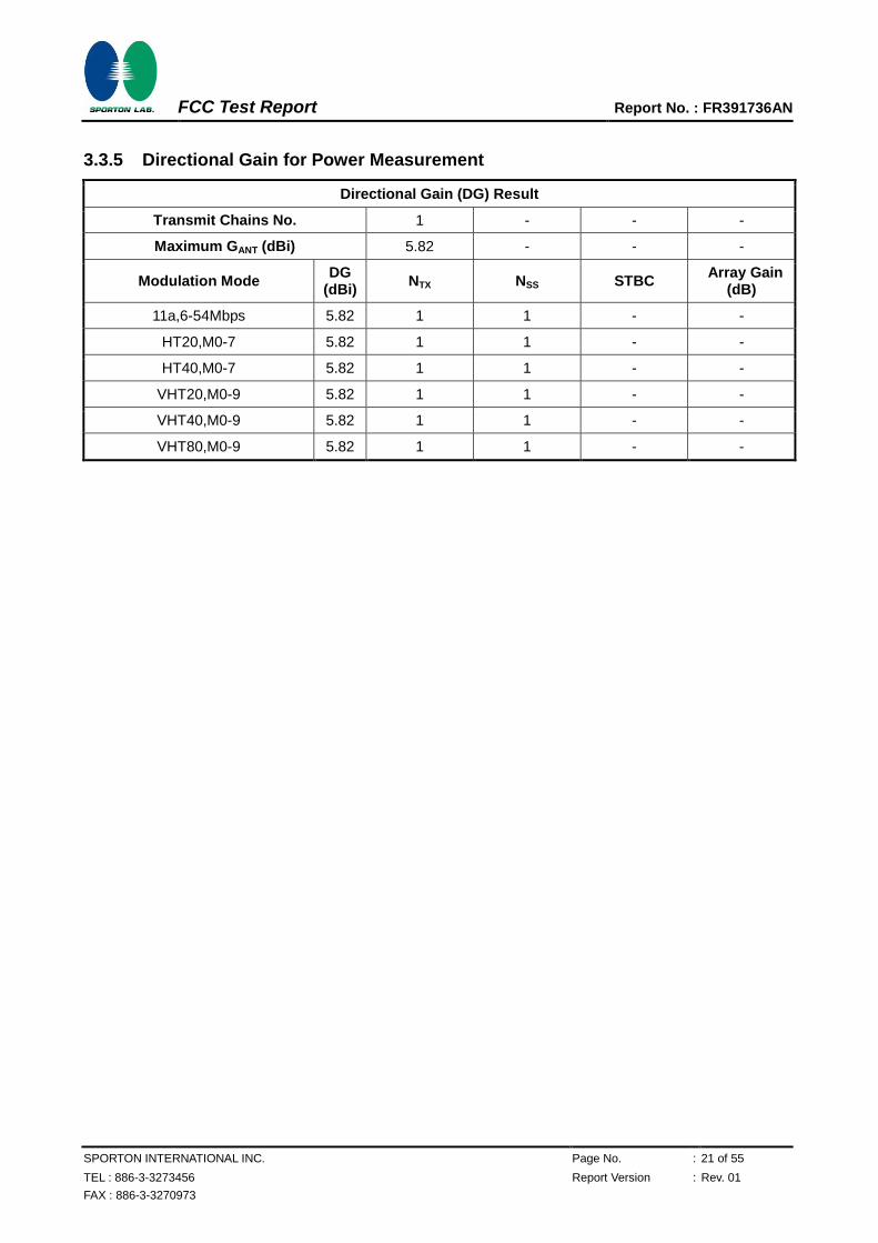
3.3.5 Directional Gain for Power Measurement
Directional Gain (DG) Result
Transmit Chains No. 1 - - -
Maximum GANT (dBi) 5.82 - - -
Modulation Mode DG
(dBi) NTX NSS STBC
Array Gain (dB)
11a,6-54Mbps 5.82 1 1 - -
HT20,M0-7 5.82 1 1 - -
HT40,M0-7 5.82 1 1 - -
VHT20,M0-9 5.82 1 1 - -
VHT40,M0-9 5.82 1 1 - -
VHT80,M0-9 5.82 1 1 - -
FCC Test Report Report No. : FR391736AN
SPORTON INTERNATIONAL INC. Page No. : 22 of 55
TEL : 886-3-3273456 Report Version : Rev. 01
FAX : 886-3-3270973
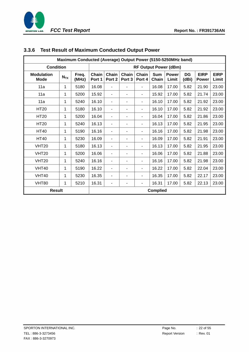
3.3.6 Test Result of Maximum Conducted Output Power
Maximum Conducted (Average) Output Power (5150-5250MHz band)
Condition RF Output Power (dBm)
Modulation Mode
NTX Freq. (MHz)
Chain Port 1
Chain Port 2
Chain Port 3
Chain Port 4
Sum Chain
Power Limit
DG (dBi)
EIRP Power
EIRP Limit
11a 1 5180 16.08 - - - 16.08 17.00 5.82 21.90 23.00
11a 1 5200 15.92 - - - 15.92 17.00 5.82 21.74 23.00
11a 1 5240 16.10 - - - 16.10 17.00 5.82 21.92 23.00
HT20 1 5180 16.10 - - - 16.10 17.00 5.82 21.92 23.00
HT20 1 5200 16.04 - - - 16.04 17.00 5.82 21.86 23.00
HT20 1 5240 16.13 - - - 16.13 17.00 5.82 21.95 23.00
HT40 1 5190 16.16 - - - 16.16 17.00 5.82 21.98 23.00
HT40 1 5230 16.09 - - - 16.09 17.00 5.82 21.91 23.00
VHT20 1 5180 16.13 - - - 16.13 17.00 5.82 21.95 23.00
VHT20 1 5200 16.06 - - - 16.06 17.00 5.82 21.88 23.00
VHT20 1 5240 16.16 - - - 16.16 17.00 5.82 21.98 23.00
VHT40 1 5190 16.22 - - - 16.22 17.00 5.82 22.04 23.00
VHT40 1 5230 16.35 - - - 16.35 17.00 5.82 22.17 23.00
VHT80 1 5210 16.31 - - - 16.31 17.00 5.82 22.13 23.00
Result Complied
FCC Test Report Report No. : FR391736AN
SPORTON INTERNATIONAL INC. Page No. : 23 of 55
TEL : 886-3-3273456 Report Version : Rev. 01
FAX : 886-3-3270973
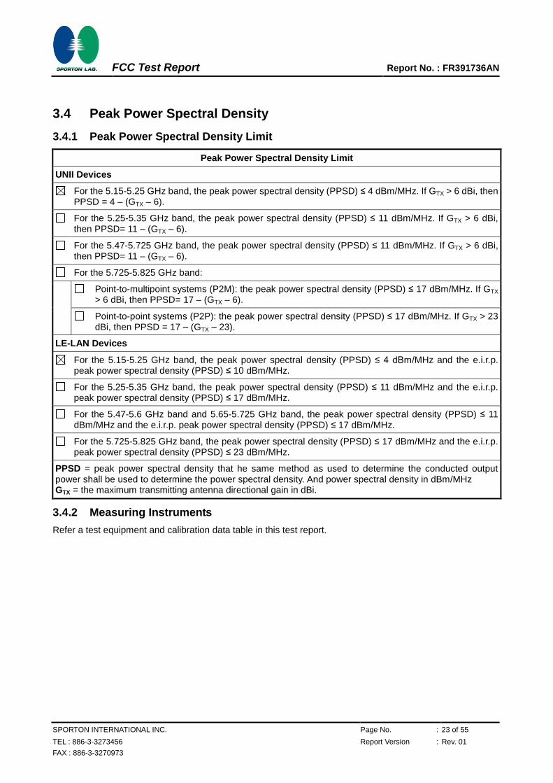
3.4 Peak Power Spectral Density
3.4.1 Peak Power Spectral Density Limit
Peak Power Spectral Density Limit
UNII Devices
For the 5.15-5.25 GHz band, the peak power spectral density (PPSD) ≤ 4 dBm/MHz. If GTX > 6 dBi, then PPSD = 4 – (GTX – 6).
For the 5.25-5.35 GHz band, the peak power spectral density (PPSD) ≤ 11 dBm/MHz. If GTX > 6 dBi, then PPSD= 11 – (GTX – 6).
For the 5.47-5.725 GHz band, the peak power spectral density (PPSD) ≤ 11 dBm/MHz. If GTX > 6 dBi, then PPSD= 11 – (GTX – 6).
For the 5.725-5.825 GHz band:
Point-to-multipoint systems (P2M): the peak power spectral density (PPSD) ≤ 17 dBm/MHz. If GTX > 6 dBi, then PPSD= 17 – (GTX – 6).
Point-to-point systems (P2P): the peak power spectral density (PPSD) ≤ 17 dBm/MHz. If GTX > 23 dBi, then PPSD = 17 – (GTX – 23).
LE-LAN Devices
For the 5.15-5.25 GHz band, the peak power spectral density (PPSD) ≤ 4 dBm/MHz and the e.i.r.p. peak power spectral density (PPSD) ≤ 10 dBm/MHz.
For the 5.25-5.35 GHz band, the peak power spectral density (PPSD) ≤ 11 dBm/MHz and the e.i.r.p. peak power spectral density (PPSD) ≤ 17 dBm/MHz.
For the 5.47-5.6 GHz band and 5.65-5.725 GHz band, the peak power spectral density (PPSD) ≤ 11 dBm/MHz and the e.i.r.p. peak power spectral density (PPSD) ≤ 17 dBm/MHz.
For the 5.725-5.825 GHz band, the peak power spectral density (PPSD) ≤ 17 dBm/MHz and the e.i.r.p. peak power spectral density (PPSD) ≤ 23 dBm/MHz.
PPSD = peak power spectral density that he same method as used to determine the conducted output power shall be used to determine the power spectral density. And power spectral density in dBm/MHz GTX = the maximum transmitting antenna directional gain in dBi.
3.4.2 Measuring Instruments
Refer a test equipment and calibration data table in this test report.
FCC Test Report Report No. : FR391736AN
SPORTON INTERNATIONAL INC. Page No. : 24 of 55
TEL : 886-3-3273456 Report Version : Rev. 01
FAX : 886-3-3270973
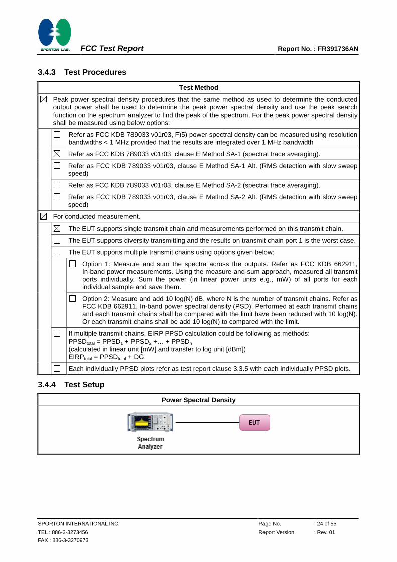
3.4.3 Test Procedures
Test Method
Peak power spectral density procedures that the same method as used to determine the conducted output power shall be used to determine the peak power spectral density and use the peak search function on the spectrum analyzer to find the peak of the spectrum. For the peak power spectral density shall be measured using below options:
Refer as FCC KDB 789033 v01r03, F)5) power spectral density can be measured using resolution bandwidths < 1 MHz provided that the results are integrated over 1 MHz bandwidth
Refer as FCC KDB 789033 v01r03, clause E Method SA-1 (spectral trace averaging).
Refer as FCC KDB 789033 v01r03, clause E Method SA-1 Alt. (RMS detection with slow sweep speed)
Refer as FCC KDB 789033 v01r03, clause E Method SA-2 (spectral trace averaging).
Refer as FCC KDB 789033 v01r03, clause E Method SA-2 Alt. (RMS detection with slow sweep speed)
For conducted measurement.
The EUT supports single transmit chain and measurements performed on this transmit chain.
The EUT supports diversity transmitting and the results on transmit chain port 1 is the worst case.
The EUT supports multiple transmit chains using options given below:
Option 1: Measure and sum the spectra across the outputs. Refer as FCC KDB 662911, In-band power measurements. Using the measure-and-sum approach, measured all transmit ports individually. Sum the power (in linear power units e.g., mW) of all ports for each individual sample and save them.
Option 2: Measure and add 10 log(N) dB, where N is the number of transmit chains. Refer as FCC KDB 662911, In-band power spectral density (PSD). Performed at each transmit chains and each transmit chains shall be compared with the limit have been reduced with 10 log(N). Or each transmit chains shall be add 10 log(N) to compared with the limit.
If multiple transmit chains, EIRP PPSD calculation could be following as methods: PPSDtotal = PPSD1 + PPSD2 +… + PPSDn (calculated in linear unit [mW] and transfer to log unit [dBm]) EIRPtotal = PPSDtotal + DG
Each individually PPSD plots refer as test report clause 3.3.5 with each individually PPSD plots.
3.4.4 Test Setup
Power Spectral Density
FCC Test Report Report No. : FR391736AN
SPORTON INTERNATIONAL INC. Page No. : 25 of 55
TEL : 886-3-3273456 Report Version : Rev. 01
FAX : 886-3-3270973
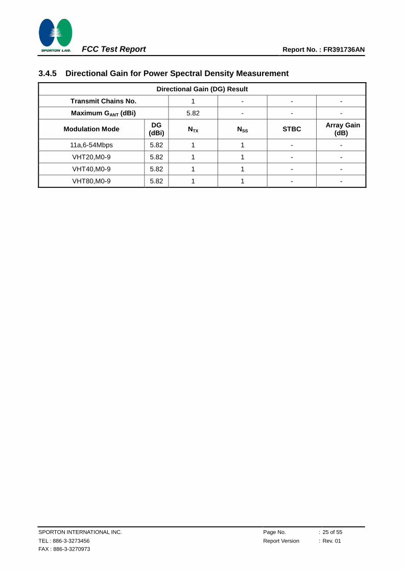
3.4.5 Directional Gain for Power Spectral Density Measurement
Directional Gain (DG) Result
Transmit Chains No. 1 - - -
Maximum GANT (dBi) 5.82 - - -
Modulation Mode DG
(dBi) NTX NSS STBC
Array Gain (dB)
11a,6-54Mbps 5.82 1 1 - -
VHT20,M0-9 5.82 1 1 - -
VHT40,M0-9 5.82 1 1 - -
VHT80,M0-9 5.82 1 1 - -
FCC Test Report Report No. : FR391736AN
SPORTON INTERNATIONAL INC. Page No. : 26 of 55
TEL : 886-3-3273456 Report Version : Rev. 01
FAX : 886-3-3270973
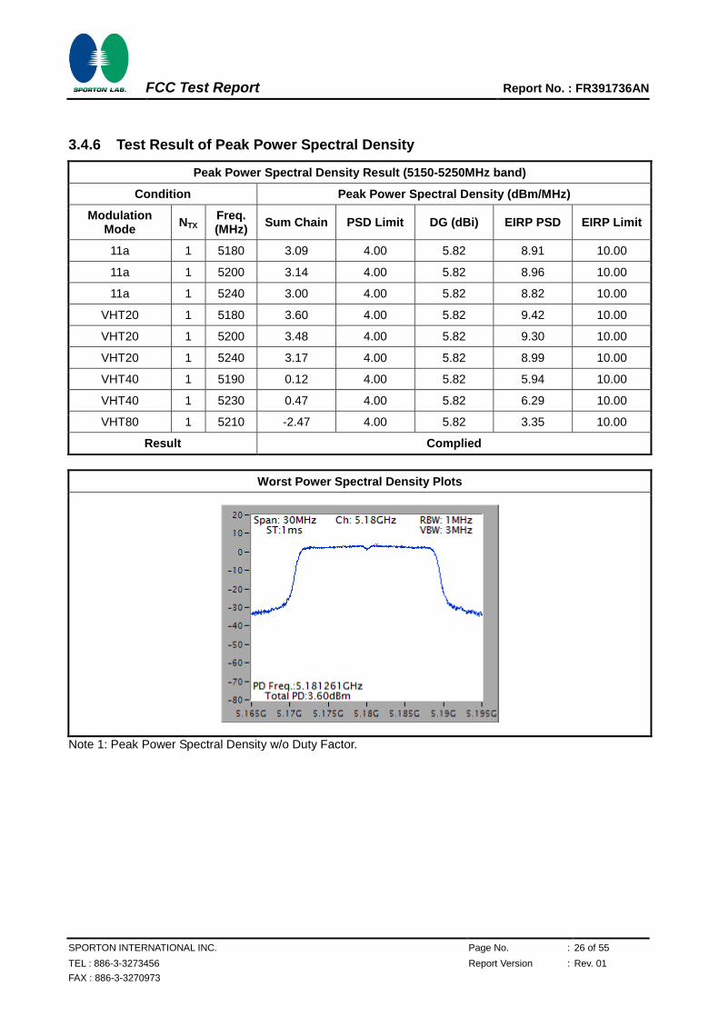
3.4.6 Test Result of Peak Power Spectral Density
Peak Power Spectral Density Result (5150-5250MHz band)
Condition Peak Power Spectral Density (dBm/MHz)
Modulation Mode
NTX Freq. (MHz)
Sum Chain PSD Limit DG (dBi) EIRP PSD EIRP Limit
11a 1 5180 3.09 4.00 5.82 8.91 10.00
11a 1 5200 3.14 4.00 5.82 8.96 10.00
11a 1 5240 3.00 4.00 5.82 8.82 10.00
VHT20 1 5180 3.60 4.00 5.82 9.42 10.00
VHT20 1 5200 3.48 4.00 5.82 9.30 10.00
VHT20 1 5240 3.17 4.00 5.82 8.99 10.00
VHT40 1 5190 0.12 4.00 5.82 5.94 10.00
VHT40 1 5230 0.47 4.00 5.82 6.29 10.00
VHT80 1 5210 -2.47 4.00 5.82 3.35 10.00
Result Complied
Worst Power Spectral Density Plots
Note 1: Peak Power Spectral Density w/o Duty Factor.
FCC Test Report Report No. : FR391736AN
SPORTON INTERNATIONAL INC. Page No. : 27 of 55
TEL : 886-3-3273456 Report Version : Rev. 01
FAX : 886-3-3270973
3.5 Peak Excursion
3.5.1 Peak Excursion Limit
Peak Excursion Limit
UNII Devices
Peak excursion ≤ 13 dB. The ratio of the maximum of the peak-max-hold spectrum to the maximum of the average spectrum for continuous transmission does not exceed 13 dB. (Earlier procedures that required computing the ratio of the two spectra at each frequency across the emission bandwidth can lead to unintended failures at band edges and will no longer be required.)
LE-LAN Devices
N/A
3.5.2 Measuring Instruments
Refer a test equipment and calibration data table in this test report.
3.5.3 Test Procedures
Test Method
Refer as FCC KDB 789033 v01r03, clause G peak excursion method.
Testing each modulation mode on a single channel is sufficient to demonstrate compliance with the peak excursion requirement
For conducted measurement.
Testing a single output port is sufficient to demonstrate compliance with the peak excursion.
Test result plots refer as test report clause 3.3.5 with peak excursion ratio of the maximum of the peak-max-hold spectrum to the maximum of the average spectrum.
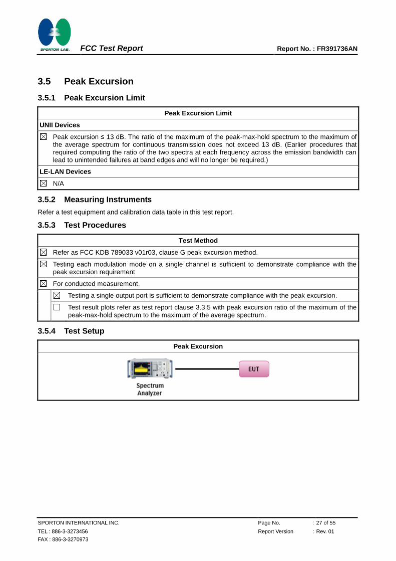
3.5.4 Test Setup
Peak Excursion
FCC Test Report Report No. : FR391736AN
SPORTON INTERNATIONAL INC. Page No. : 28 of 55
TEL : 886-3-3273456 Report Version : Rev. 01
FAX : 886-3-3270973
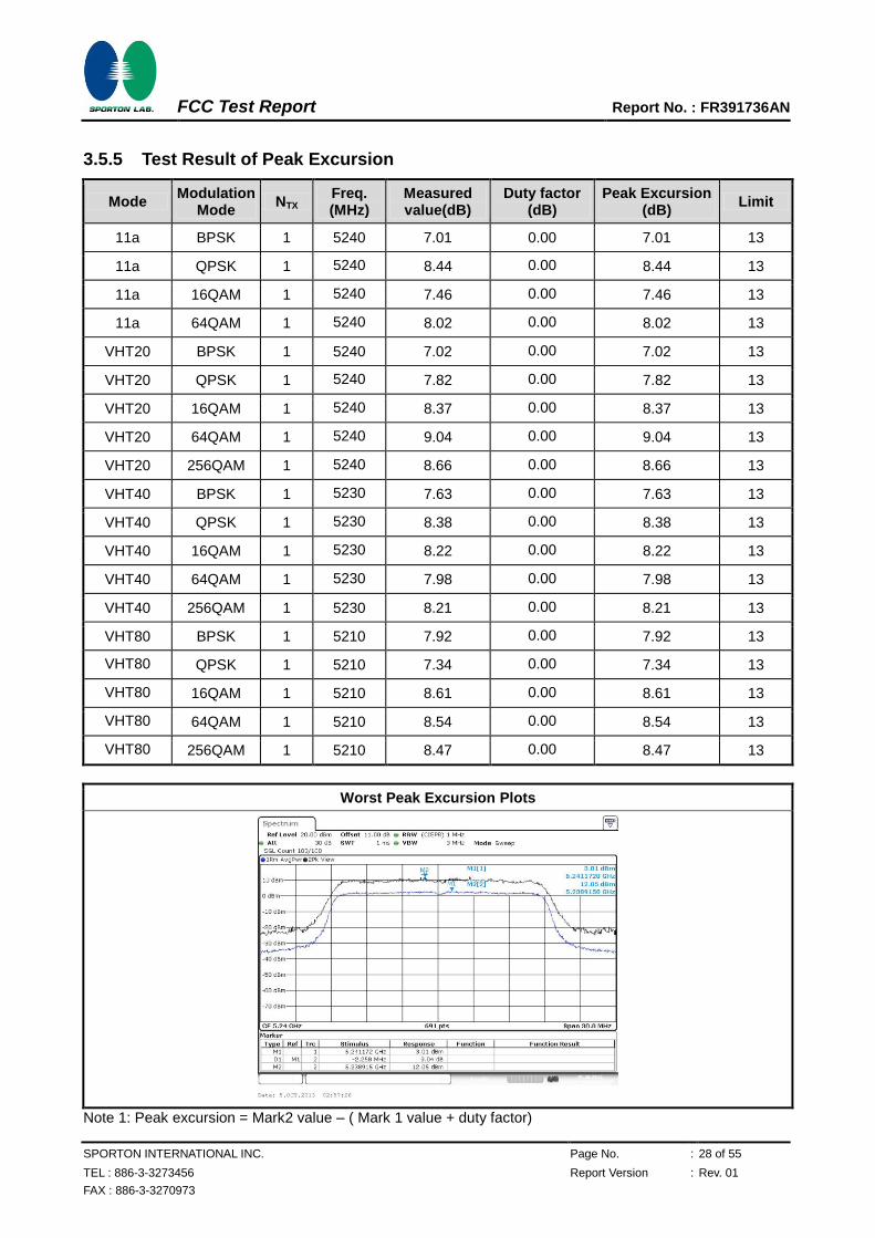
3.5.5 Test Result of Peak Excursion
Mode Modulation
Mode NTX
Freq. (MHz)
Measured value(dB)
Duty factor (dB)
Peak Excursion (dB)
Limit
11a BPSK 1 5240 7.01 0.00 7.01 13
11a QPSK 1 5240 8.44 0.00 8.44 13
11a 16QAM 1 5240 7.46 0.00 7.46 13
11a 64QAM 1 5240 8.02 0.00 8.02 13
VHT20 BPSK 1 5240 7.02 0.00 7.02 13
VHT20 QPSK 1 5240 7.82 0.00 7.82 13
VHT20 16QAM 1 5240 8.37 0.00 8.37 13
VHT20 64QAM 1 5240 9.04 0.00 9.04 13
VHT20 256QAM 1 5240 8.66 0.00 8.66 13
VHT40 BPSK 1 5230 7.63 0.00 7.63 13
VHT40 QPSK 1 5230 8.38 0.00 8.38 13
VHT40 16QAM 1 5230 8.22 0.00 8.22 13
VHT40 64QAM 1 5230 7.98 0.00 7.98 13
VHT40 256QAM 1 5230 8.21 0.00 8.21 13
VHT80 BPSK 1 5210 7.92 0.00 7.92 13
VHT80 QPSK 1 5210 7.34 0.00 7.34 13
VHT80 16QAM 1 5210 8.61 0.00 8.61 13
VHT80 64QAM 1 5210 8.54 0.00 8.54 13
VHT80 256QAM 1 5210 8.47 0.00 8.47 13
Worst Peak Excursion Plots
Note 1: Peak excursion = Mark2 value – ( Mark 1 value + duty factor)
FCC Test Report Report No. : FR391736AN
SPORTON INTERNATIONAL INC. Page No. : 29 of 55
TEL : 886-3-3273456 Report Version : Rev. 01
FAX : 886-3-3270973
3.6 Transmitter Radiated Unwanted Emissions and Band Edge
3.6.1 Transmitter Radiated Unwanted Emissions and Band Edge Limit
Unwanted emissions below 1 GHz and restricted band emissions above 1GHz limit
Frequency Range (MHz) Field Strength (uV/m) Field Strength (dBuV/m) Measure Distance (m)
0.009~0.490 2400/F(kHz) 48.5 - 13.8 300
0.490~1.705 24000/F(kHz) 33.8 - 23 30
1.705~30.0 30 29 30
30~88 100 40 3
88~216 150 43.5 3
216~960 200 46 3
Above 960 500 54 3
Note 1: Test distance for frequencies at or above 30 MHz, measurements may be performed at a distance other than the limit distance provided they are not performed in the near field and the emissions to be measured can be detected by the measurement equipment. When performing measurements at a distance other than that specified, the results shall be extrapolated to the specified distance using an extrapolation factor of 20 dB/decade (inverse of linear distance for field-strength measurements, inverse of linear distance-squared for power-density measurements).
Note 2: Test distance for frequencies at below 30 MHz, measurements may be performed at a distance closer than the EUT limit distance; however, an attempt should be made to avoid making measurements in the near field. When performing measurements below 30 MHz at a closer distance than the limit distance, the results shall be extrapolated to the specified distance by either making measurements at a minimum of two or more distances on at least one radial to determine the proper extrapolation factor or by using the square of an inverse linear distance extrapolation factor (40 dB/decade). The test report shall specify the extrapolation method used to determine compliance of the EUT.
Un-restricted band emissions above 1GHz Limit
Operating Band Limit
5.15 - 5.25 GHz e.i.r.p. -27 dBm [68.2 dBuV/m@3m]
5.25 - 5.35 GHz e.i.r.p. -27 dBm [68.2 dBuV/m@3m]
5.47 - 5.725 GHz e.i.r.p. -27 dBm [68.2 dBuV/m@3m]
5.725 - 5.825 GHz 5.715 5.725 GHz: e.i.r.p. -17 dBm [78.2 dBuV/m@3m] 5.825 5.835 GHz: e.i.r.p. -17 dBm [78.2 dBuV/m@3m]
Other un-restricted band: e.i.r.p. -27 dBm [68.2 dBuV/m@3m]
Note 1: Measurements may be performed at a distance other than the limit distance provided they are not performed in the near field and the emissions to be measured can be detected by the measurement equipment. When performing measurements at a distance other than that specified, the results shall be extrapolated to the specified distance using an extrapolation factor of 20 dB/decade (inverse of linear distance for field-strength measurements, inverse of linear distance-squared for power-density measurements).
3.6.2 Measuring Instruments
Refer a test equipment and calibration data table in this test report.
FCC Test Report Report No. : FR391736AN
SPORTON INTERNATIONAL INC. Page No. : 30 of 55
TEL : 886-3-3273456 Report Version : Rev. 01
FAX : 886-3-3270973
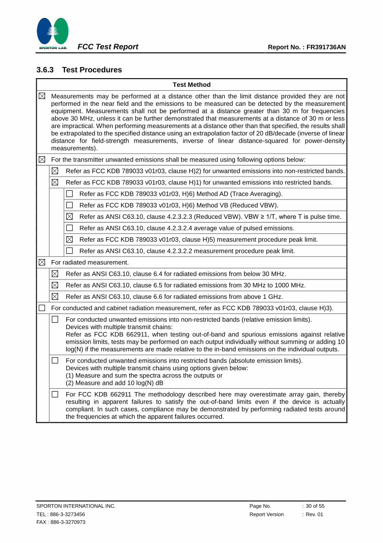
3.6.3 Test Procedures
Test Method
Measurements may be performed at a distance other than the limit distance provided they are not performed in the near field and the emissions to be measured can be detected by the measurement equipment. Measurements shall not be performed at a distance greater than 30 m for frequencies above 30 MHz, unless it can be further demonstrated that measurements at a distance of 30 m or less are impractical. When performing measurements at a distance other than that specified, the results shall be extrapolated to the specified distance using an extrapolation factor of 20 dB/decade (inverse of linear distance for field-strength measurements, inverse of linear distance-squared for power-density measurements).
For the transmitter unwanted emissions shall be measured using following options below:
Refer as FCC KDB 789033 v01r03, clause H)2) for unwanted emissions into non-restricted bands.
Refer as FCC KDB 789033 v01r03, clause H)1) for unwanted emissions into restricted bands.
Refer as FCC KDB 789033 v01r03, H)6) Method AD (Trace Averaging).
Refer as FCC KDB 789033 v01r03, H)6) Method VB (Reduced VBW).
Refer as ANSI C63.10, clause 4.2.3.2.3 (Reduced VBW). VBW ≥ 1/T, where T is pulse time.
Refer as ANSI C63.10, clause 4.2.3.2.4 average value of pulsed emissions.
Refer as FCC KDB 789033 v01r03, clause H)5) measurement procedure peak limit.
Refer as ANSI C63.10, clause 4.2.3.2.2 measurement procedure peak limit.
For radiated measurement.
Refer as ANSI C63.10, clause 6.4 for radiated emissions from below 30 MHz.
Refer as ANSI C63.10, clause 6.5 for radiated emissions from 30 MHz to 1000 MHz.
Refer as ANSI C63.10, clause 6.6 for radiated emissions from above 1 GHz.
For conducted and cabinet radiation measurement, refer as FCC KDB 789033 v01r03, clause H)3).
For conducted unwanted emissions into non-restricted bands (relative emission limits). Devices with multiple transmit chains: Refer as FCC KDB 662911, when testing out-of-band and spurious emissions against relative emission limits, tests may be performed on each output individually without summing or adding 10 log(N) if the measurements are made relative to the in-band emissions on the individual outputs.
For conducted unwanted emissions into restricted bands (absolute emission limits). Devices with multiple transmit chains using options given below: (1) Measure and sum the spectra across the outputs or (2) Measure and add 10 log(N) dB
For FCC KDB 662911 The methodology described here may overestimate array gain, thereby resulting in apparent failures to satisfy the out-of-band limits even if the device is actually compliant. In such cases, compliance may be demonstrated by performing radiated tests around the frequencies at which the apparent failures occurred.
FCC Test Report Report No. : FR391736AN
SPORTON INTERNATIONAL INC. Page No. : 31 of 55
TEL : 886-3-3273456 Report Version : Rev. 01
FAX : 886-3-3270973
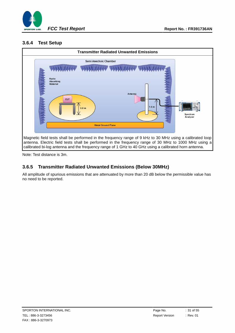
3.6.4 Test Setup
Transmitter Radiated Unwanted Emissions
Magnetic field tests shall be performed in the frequency range of 9 kHz to 30 MHz using a calibrated loop antenna. Electric field tests shall be performed in the frequency range of 30 MHz to 1000 MHz using a calibrated bi-log antenna and the frequency range of 1 GHz to 40 GHz using a calibrated horn antenna.
Note: Test distance is 3m.
3.6.5 Transmitter Radiated Unwanted Emissions (Below 30MHz)
All amplitude of spurious emissions that are attenuated by more than 20 dB below the permissible value has no need to be reported.
FCC Test Report Report No. : FR391736AN
SPORTON INTERNATIONAL INC. Page No. : 32 of 55
TEL : 886-3-3273456 Report Version : Rev. 01
FAX : 886-3-3270973
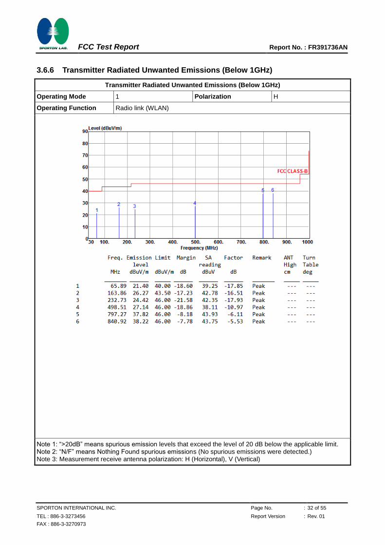
3.6.6 Transmitter Radiated Unwanted Emissions (Below 1GHz)
Transmitter Radiated Unwanted Emissions (Below 1GHz)
Operating Mode 1 Polarization H
Operating Function Radio link (WLAN)
Note 1: “>20dB” means spurious emission levels that exceed the level of 20 dB below the applicable limit. Note 2: “N/F” means Nothing Found spurious emissions (No spurious emissions were detected.) Note 3: Measurement receive antenna polarization: H (Horizontal), V (Vertical)
FCC Test Report Report No. : FR391736AN
SPORTON INTERNATIONAL INC. Page No. : 33 of 55
TEL : 886-3-3273456 Report Version : Rev. 01
FAX : 886-3-3270973
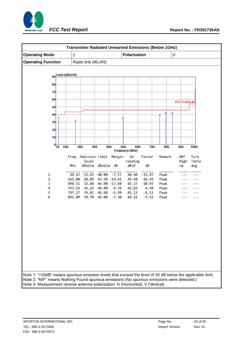
Transmitter Radiated Unwanted Emissions (Below 1GHz)
Operating Mode 1 Polarization V
Operating Function Radio link (WLAN)
Note 1: “>20dB” means spurious emission levels that exceed the level of 20 dB below the applicable limit. Note 2: “N/F” means Nothing Found spurious emissions (No spurious emissions were detected.) Note 3: Measurement receive antenna polarization: H (Horizontal), V (Vertical)

FCC Test Report Report No. : FR391736AN
SPORTON INTERNATIONAL INC. Page No. : 34 of 55
TEL : 886-3-3273456 Report Version : Rev. 01
FAX : 886-3-3270973
3.6.7 Transmitter Radiated Unwanted Emissions (Above 1GHz) for 11a
Transmitter Radiated Unwanted Emissions (Above 1GHz)
Modulation Mode 11a Test Freq. (MHz) 5180
NTX 1 Polarization H
Note 1: “>20dB” means spurious emission levels that exceed the level of 20 dB below the applicable limit. Note 2: “N/F” means Nothing Found spurious emissions (No spurious emissions were detected.) Note 3: Measurement receive antenna polarization: H (Horizontal), V (Vertical) Note 4: For restricted bands, the peak measurement is fully sufficient, as the max field strength as measured
with the Peak-Detector meets the AV-Limit so that the AV level does not need to be reported in addition.

FCC Test Report Report No. : FR391736AN
SPORTON INTERNATIONAL INC. Page No. : 35 of 55
TEL : 886-3-3273456 Report Version : Rev. 01
FAX : 886-3-3270973
Transmitter Radiated Unwanted Emissions (Above 1GHz)
Modulation Mode 11a Test Freq. (MHz) 5180
NTX 1 Polarization V
Note 1: “>20dB” means spurious emission levels that exceed the level of 20 dB below the applicable limit. Note 2: “N/F” means Nothing Found spurious emissions (No spurious emissions were detected.) Note 3: Measurement receive antenna polarization: H (Horizontal), V (Vertical) Note 4: For restricted bands, the peak measurement is fully sufficient, as the max field strength as measured
with the Peak-Detector meets the AV-Limit so that the AV level does not need to be reported in addition.
FCC Test Report Report No. : FR391736AN
SPORTON INTERNATIONAL INC. Page No. : 36 of 55
TEL : 886-3-3273456 Report Version : Rev. 01
FAX : 886-3-3270973
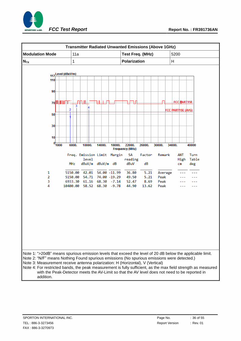
Transmitter Radiated Unwanted Emissions (Above 1GHz)
Modulation Mode 11a Test Freq. (MHz) 5200
NTX 1 Polarization H
Note 1: “>20dB” means spurious emission levels that exceed the level of 20 dB below the applicable limit. Note 2: “N/F” means Nothing Found spurious emissions (No spurious emissions were detected.) Note 3: Measurement receive antenna polarization: H (Horizontal), V (Vertical) Note 4: For restricted bands, the peak measurement is fully sufficient, as the max field strength as measured
with the Peak-Detector meets the AV-Limit so that the AV level does not need to be reported in addition.

FCC Test Report Report No. : FR391736AN
SPORTON INTERNATIONAL INC. Page No. : 37 of 55
TEL : 886-3-3273456 Report Version : Rev. 01
FAX : 886-3-3270973
Transmitter Radiated Unwanted Emissions (Above 1GHz)
Modulation Mode 11a Test Freq. (MHz) 5200
NTX 1 Polarization V
Note 1: “>20dB” means spurious emission levels that exceed the level of 20 dB below the applicable limit. Note 2: “N/F” means Nothing Found spurious emissions (No spurious emissions were detected.) Note 3: Measurement receive antenna polarization: H (Horizontal), V (Vertical) Note 4: For restricted bands, the peak measurement is fully sufficient, as the max field strength as measured
with the Peak-Detector meets the AV-Limit so that the AV level does not need to be reported in addition.

FCC Test Report Report No. : FR391736AN
SPORTON INTERNATIONAL INC. Page No. : 38 of 55
TEL : 886-3-3273456 Report Version : Rev. 01
FAX : 886-3-3270973
Transmitter Radiated Unwanted Emissions (Above 1GHz)
Modulation Mode 11a Test Freq. (MHz) 5240
NTX 1 Polarization H
Note 1: “>20dB” means spurious emission levels that exceed the level of 20 dB below the applicable limit. Note 2: “N/F” means Nothing Found spurious emissions (No spurious emissions were detected.) Note 3: Measurement receive antenna polarization: H (Horizontal), V (Vertical) Note 4: For restricted bands, the peak measurement is fully sufficient, as the max field strength as measured
with the Peak-Detector meets the AV-Limit so that the AV level does not need to be reported in addition.

FCC Test Report Report No. : FR391736AN
SPORTON INTERNATIONAL INC. Page No. : 39 of 55
TEL : 886-3-3273456 Report Version : Rev. 01
FAX : 886-3-3270973
Transmitter Radiated Unwanted Emissions (Above 1GHz)
Modulation Mode 11a Test Freq. (MHz) 5240
NTX 1 Polarization V
Note 1: “>20dB” means spurious emission levels that exceed the level of 20 dB below the applicable limit. Note 2: “N/F” means Nothing Found spurious emissions (No spurious emissions were detected.) Note 3: Measurement receive antenna polarization: H (Horizontal), V (Vertical) Note 4: For restricted bands, the peak measurement is fully sufficient, as the max field strength as measured
with the Peak-Detector meets the AV-Limit so that the AV level does not need to be reported in addition.
FCC Test Report Report No. : FR391736AN
SPORTON INTERNATIONAL INC. Page No. : 40 of 55
TEL : 886-3-3273456 Report Version : Rev. 01
FAX : 886-3-3270973
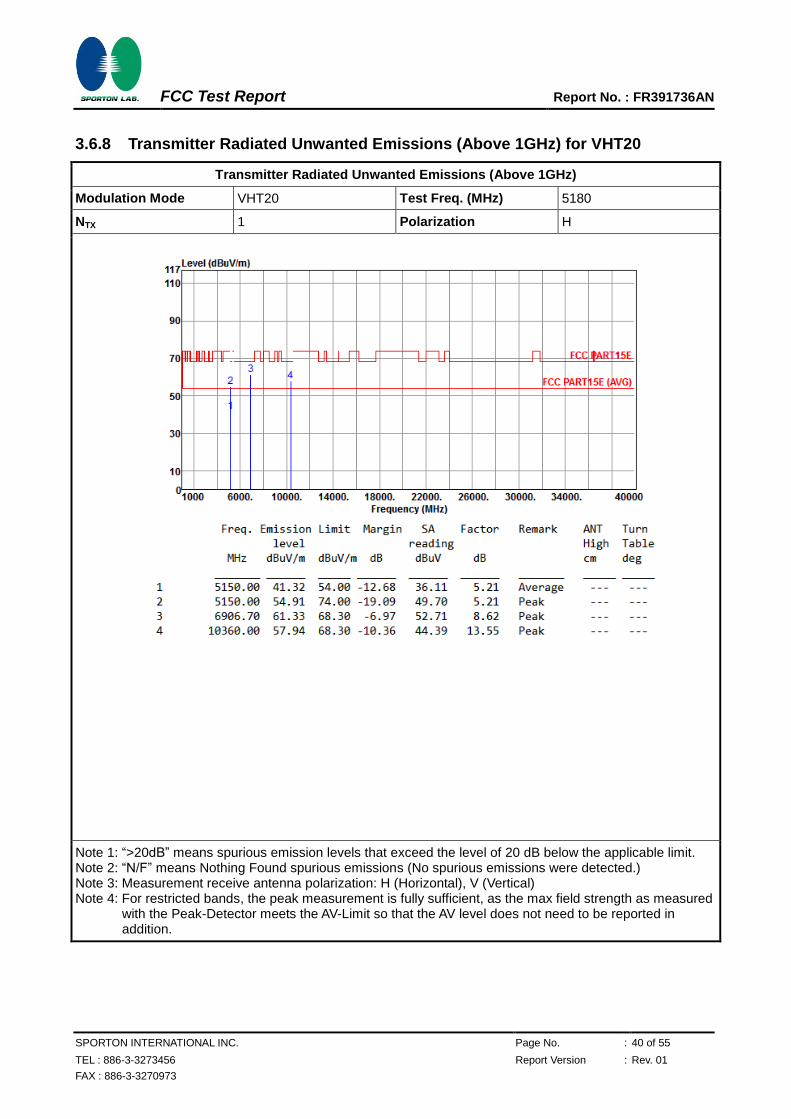
3.6.8 Transmitter Radiated Unwanted Emissions (Above 1GHz) for VHT20
Transmitter Radiated Unwanted Emissions (Above 1GHz)
Modulation Mode VHT20 Test Freq. (MHz) 5180
NTX 1 Polarization H
Note 1: “>20dB” means spurious emission levels that exceed the level of 20 dB below the applicable limit. Note 2: “N/F” means Nothing Found spurious emissions (No spurious emissions were detected.) Note 3: Measurement receive antenna polarization: H (Horizontal), V (Vertical) Note 4: For restricted bands, the peak measurement is fully sufficient, as the max field strength as measured
with the Peak-Detector meets the AV-Limit so that the AV level does not need to be reported in addition.
FCC Test Report Report No. : FR391736AN
SPORTON INTERNATIONAL INC. Page No. : 41 of 55
TEL : 886-3-3273456 Report Version : Rev. 01
FAX : 886-3-3270973
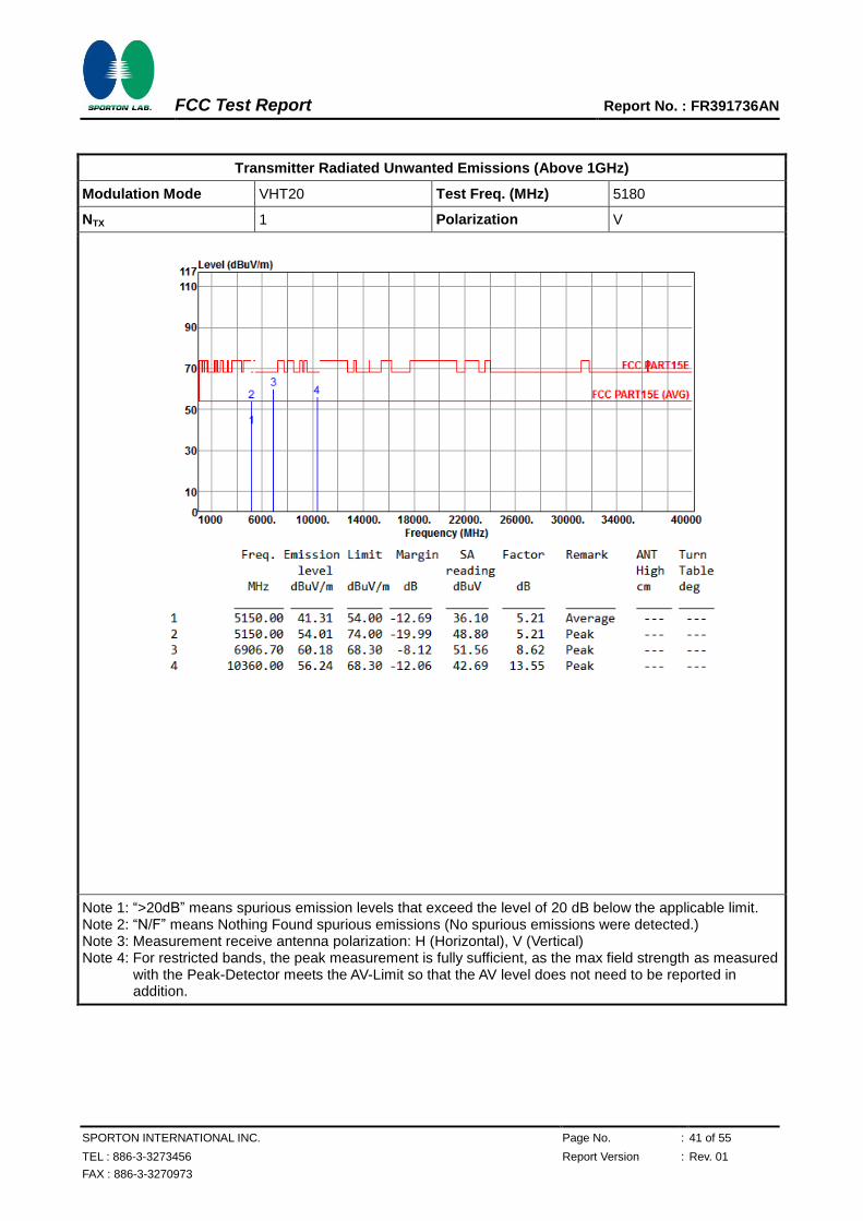
Transmitter Radiated Unwanted Emissions (Above 1GHz)
Modulation Mode VHT20 Test Freq. (MHz) 5180
NTX 1 Polarization V
Note 1: “>20dB” means spurious emission levels that exceed the level of 20 dB below the applicable limit. Note 2: “N/F” means Nothing Found spurious emissions (No spurious emissions were detected.) Note 3: Measurement receive antenna polarization: H (Horizontal), V (Vertical) Note 4: For restricted bands, the peak measurement is fully sufficient, as the max field strength as measured
with the Peak-Detector meets the AV-Limit so that the AV level does not need to be reported in addition.

FCC Test Report Report No. : FR391736AN
SPORTON INTERNATIONAL INC. Page No. : 42 of 55
TEL : 886-3-3273456 Report Version : Rev. 01
FAX : 886-3-3270973
Transmitter Radiated Unwanted Emissions (Above 1GHz)
Modulation Mode VHT20 Test Freq. (MHz) 5200
NTX 1 Polarization H
Note 1: “>20dB” means spurious emission levels that exceed the level of 20 dB below the applicable limit. Note 2: “N/F” means Nothing Found spurious emissions (No spurious emissions were detected.) Note 3: Measurement receive antenna polarization: H (Horizontal), V (Vertical) Note 4: For restricted bands, the peak measurement is fully sufficient, as the max field strength as measured
with the Peak-Detector meets the AV-Limit so that the AV level does not need to be reported in addition.

FCC Test Report Report No. : FR391736AN
SPORTON INTERNATIONAL INC. Page No. : 43 of 55
TEL : 886-3-3273456 Report Version : Rev. 01
FAX : 886-3-3270973
Transmitter Radiated Unwanted Emissions (Above 1GHz)
Modulation Mode VHT20 Test Freq. (MHz) 5200
NTX 1 Polarization V
Note 1: “>20dB” means spurious emission levels that exceed the level of 20 dB below the applicable limit. Note 2: “N/F” means Nothing Found spurious emissions (No spurious emissions were detected.) Note 3: Measurement receive antenna polarization: H (Horizontal), V (Vertical) Note 4: For restricted bands, the peak measurement is fully sufficient, as the max field strength as measured
with the Peak-Detector meets the AV-Limit so that the AV level does not need to be reported in addition.

FCC Test Report Report No. : FR391736AN
SPORTON INTERNATIONAL INC. Page No. : 44 of 55
TEL : 886-3-3273456 Report Version : Rev. 01
FAX : 886-3-3270973
Transmitter Radiated Unwanted Emissions (Above 1GHz)
Modulation Mode VHT20 Test Freq. (MHz) 5240
NTX 1 Polarization H
Note 1: “>20dB” means spurious emission levels that exceed the level of 20 dB below the applicable limit. Note 2: “N/F” means Nothing Found spurious emissions (No spurious emissions were detected.) Note 3: Measurement receive antenna polarization: H (Horizontal), V (Vertical) Note 4: For restricted bands, the peak measurement is fully sufficient, as the max field strength as measured
with the Peak-Detector meets the AV-Limit so that the AV level does not need to be reported in addition.

FCC Test Report Report No. : FR391736AN
SPORTON INTERNATIONAL INC. Page No. : 45 of 55
TEL : 886-3-3273456 Report Version : Rev. 01
FAX : 886-3-3270973
Transmitter Radiated Unwanted Emissions (Above 1GHz)
Modulation Mode VHT20 Test Freq. (MHz) 5240
NTX 1 Polarization V
Note 1: “>20dB” means spurious emission levels that exceed the level of 20 dB below the applicable limit. Note 2: “N/F” means Nothing Found spurious emissions (No spurious emissions were detected.) Note 3: Measurement receive antenna polarization: H (Horizontal), V (Vertical) Note 4: For restricted bands, the peak measurement is fully sufficient, as the max field strength as measured
with the Peak-Detector meets the AV-Limit so that the AV level does not need to be reported in addition.
FCC Test Report Report No. : FR391736AN
SPORTON INTERNATIONAL INC. Page No. : 46 of 55
TEL : 886-3-3273456 Report Version : Rev. 01
FAX : 886-3-3270973
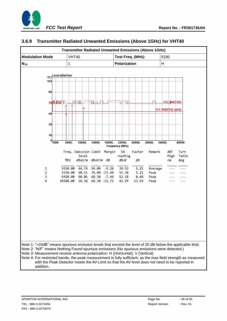
3.6.9 Transmitter Radiated Unwanted Emissions (Above 1GHz) for VHT40
Transmitter Radiated Unwanted Emissions (Above 1GHz)
Modulation Mode VHT40 Test Freq. (MHz) 5190
NTX 1 Polarization H
Note 1: “>20dB” means spurious emission levels that exceed the level of 20 dB below the applicable limit. Note 2: “N/F” means Nothing Found spurious emissions (No spurious emissions were detected.) Note 3: Measurement receive antenna polarization: H (Horizontal), V (Vertical) Note 4: For restricted bands, the peak measurement is fully sufficient, as the max field strength as measured
with the Peak-Detector meets the AV-Limit so that the AV level does not need to be reported in addition.

FCC Test Report Report No. : FR391736AN
SPORTON INTERNATIONAL INC. Page No. : 47 of 55
TEL : 886-3-3273456 Report Version : Rev. 01
FAX : 886-3-3270973
Transmitter Radiated Unwanted Emissions (Above 1GHz)
Modulation Mode VHT40 Test Freq. (MHz) 5190
NTX 1 Polarization V
Note 1: “>20dB” means spurious emission levels that exceed the level of 20 dB below the applicable limit. Note 2: “N/F” means Nothing Found spurious emissions (No spurious emissions were detected.) Note 3: Measurement receive antenna polarization: H (Horizontal), V (Vertical) Note 4: For restricted bands, the peak measurement is fully sufficient, as the max field strength as measured
with the Peak-Detector meets the AV-Limit so that the AV level does not need to be reported in addition.

FCC Test Report Report No. : FR391736AN
SPORTON INTERNATIONAL INC. Page No. : 48 of 55
TEL : 886-3-3273456 Report Version : Rev. 01
FAX : 886-3-3270973
Transmitter Radiated Unwanted Emissions (Above 1GHz)
Modulation Mode VHT40 Test Freq. (MHz) 5230
NTX 1 Polarization H
Note 1: “>20dB” means spurious emission levels that exceed the level of 20 dB below the applicable limit. Note 2: “N/F” means Nothing Found spurious emissions (No spurious emissions were detected.) Note 3: Measurement receive antenna polarization: H (Horizontal), V (Vertical) Note 4: For restricted bands, the peak measurement is fully sufficient, as the max field strength as measured
with the Peak-Detector meets the AV-Limit so that the AV level does not need to be reported in addition.

FCC Test Report Report No. : FR391736AN
SPORTON INTERNATIONAL INC. Page No. : 49 of 55
TEL : 886-3-3273456 Report Version : Rev. 01
FAX : 886-3-3270973
Transmitter Radiated Unwanted Emissions (Above 1GHz)
Modulation Mode VHT40 Test Freq. (MHz) 5230
NTX 1 Polarization V
Note 1: “>20dB” means spurious emission levels that exceed the level of 20 dB below the applicable limit. Note 2: “N/F” means Nothing Found spurious emissions (No spurious emissions were detected.) Note 3: Measurement receive antenna polarization: H (Horizontal), V (Vertical) Note 4: For restricted bands, the peak measurement is fully sufficient, as the max field strength as measured
with the Peak-Detector meets the AV-Limit so that the AV level does not need to be reported in addition.
FCC Test Report Report No. : FR391736AN
SPORTON INTERNATIONAL INC. Page No. : 50 of 55
TEL : 886-3-3273456 Report Version : Rev. 01
FAX : 886-3-3270973
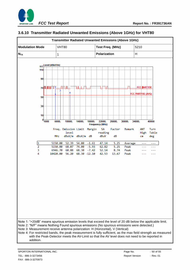
3.6.10 Transmitter Radiated Unwanted Emissions (Above 1GHz) for VHT80
Transmitter Radiated Unwanted Emissions (Above 1GHz)
Modulation Mode VHT80 Test Freq. (MHz) 5210
NTX 1 Polarization H
Note 1: “>20dB” means spurious emission levels that exceed the level of 20 dB below the applicable limit. Note 2: “N/F” means Nothing Found spurious emissions (No spurious emissions were detected.) Note 3: Measurement receive antenna polarization: H (Horizontal), V (Vertical) Note 4: For restricted bands, the peak measurement is fully sufficient, as the max field strength as measured
with the Peak-Detector meets the AV-Limit so that the AV level does not need to be reported in addition.
FCC Test Report Report No. : FR391736AN
SPORTON INTERNATIONAL INC. Page No. : 51 of 55
TEL : 886-3-3273456 Report Version : Rev. 01
FAX : 886-3-3270973
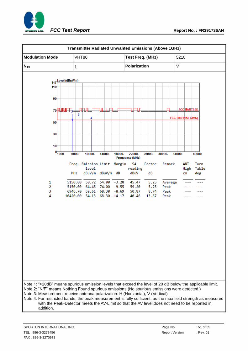
Transmitter Radiated Unwanted Emissions (Above 1GHz)
Modulation Mode VHT80 Test Freq. (MHz) 5210
NTX 1 Polarization V
Note 1: “>20dB” means spurious emission levels that exceed the level of 20 dB below the applicable limit. Note 2: “N/F” means Nothing Found spurious emissions (No spurious emissions were detected.) Note 3: Measurement receive antenna polarization: H (Horizontal), V (Vertical) Note 4: For restricted bands, the peak measurement is fully sufficient, as the max field strength as measured
with the Peak-Detector meets the AV-Limit so that the AV level does not need to be reported in addition.
FCC Test Report Report No. : FR391736AN
SPORTON INTERNATIONAL INC. Page No. : 52 of 55
TEL : 886-3-3273456 Report Version : Rev. 01
FAX : 886-3-3270973
3.7 Frequency Stability
3.7.1 Frequency Stability Limit
Frequency Stability Limit
UNII Devices
In-band emission is maintained within the band of operation under all conditions of normal operation as specified in the user’s manual.
LE-LAN Devices
N/A
IEEE Std. 802.11n-2009
The transmitter center frequency tolerance shall be ± 20 ppm maximum for the 5 GHz band and ± 25 ppm maximum for the 2.4 GHz band.
3.7.2 Measuring Instruments
Refer a test equipment and calibration data table in this test report.
3.7.3 Test Procedures
Test Method
Refer as ANSI C63.10, clause 6.8 for frequency stability tests
Frequency stability with respect to ambient temperature
Frequency stability when varying supply voltage
For conducted measurement.
For conducted measurements on devices with multiple transmit chains: Measurements need only to be performed on one of the active transmit chains (antenna outputs)
For radiated measurement. The equipment to be measured and the test antenna shall be oriented to obtain the maximum emitted power level.
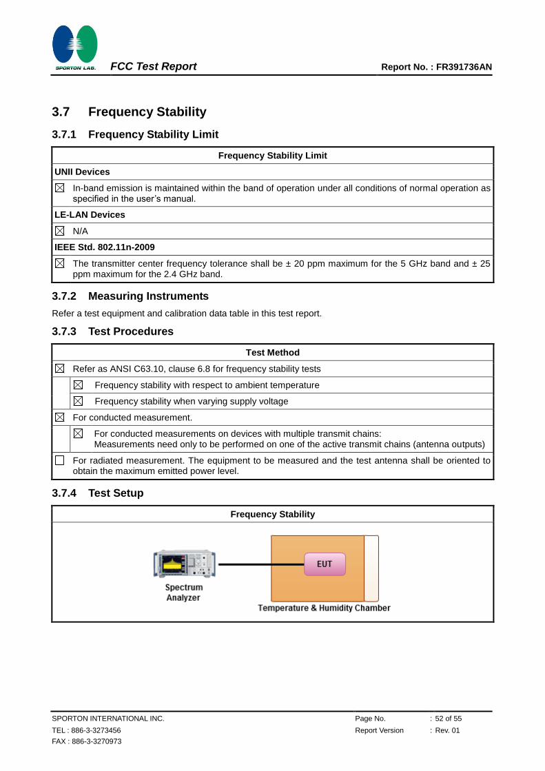
3.7.4 Test Setup
Frequency Stability
FCC Test Report Report No. : FR391736AN
SPORTON INTERNATIONAL INC. Page No. : 53 of 55
TEL : 886-3-3273456 Report Version : Rev. 01
FAX : 886-3-3270973
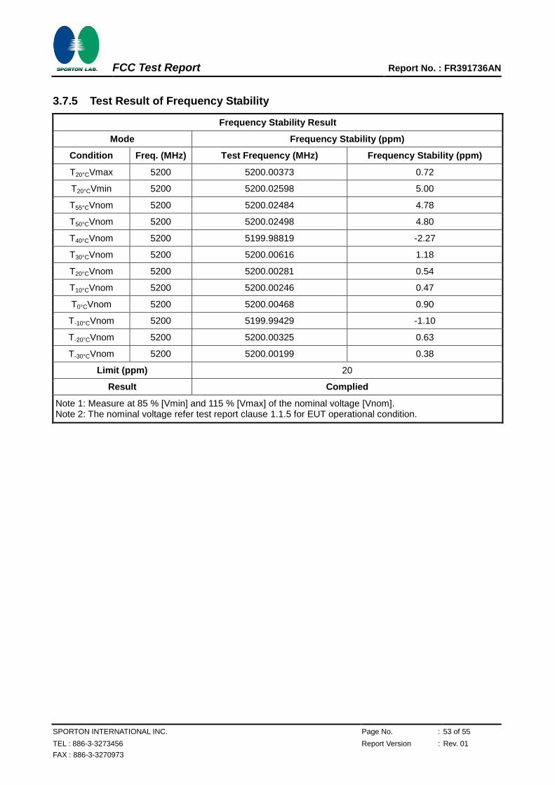
3.7.5 Test Result of Frequency Stability
Frequency Stability Result
Mode Frequency Stability (ppm)
Condition Freq. (MHz) Test Frequency (MHz) Frequency Stability (ppm)
T20°CVmax 5200 5200.00373 0.72
T20°CVmin 5200 5200.02598 5.00
T55°CVnom 5200 5200.02484 4.78
T50°CVnom 5200 5200.02498 4.80
T40°CVnom 5200 5199.98819 -2.27
T30°CVnom 5200 5200.00616 1.18
T20°CVnom 5200 5200.00281 0.54
T10°CVnom 5200 5200.00246 0.47
T0°CVnom 5200 5200.00468 0.90
T-10°CVnom 5200 5199.99429 -1.10
T-20°CVnom 5200 5200.00325 0.63
T-30°CVnom 5200 5200.00199 0.38
Limit (ppm) 20
Result Complied
Note 1: Measure at 85 % [Vmin] and 115 % [Vmax] of the nominal voltage [Vnom]. Note 2: The nominal voltage refer test report clause 1.1.5 for EUT operational condition.
FCC Test Report Report No. : FR391736AN
SPORTON INTERNATIONAL INC. Page No. : 54 of 55
TEL : 886-3-3273456 Report Version : Rev. 01
FAX : 886-3-3270973
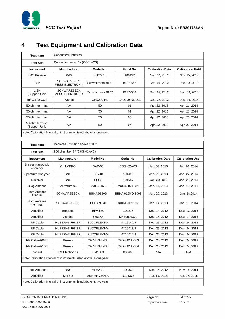
4 Test Equipment and Calibration Data
Test Item Conducted Emission
Test Site Conduction room 1 / (CO01-WS)
Instrument Manufacturer Model No. Serial No. Calibration Date Calibration Until
EMC Receiver R&S ESCS 30 100132 Nov. 14, 2012 Nov. 15, 2013
LISN SCHWARZBECK
MESS-ELEKTRONIK Schwarzbeck 8127 8127-667 Dec. 04, 2012 Dec. 03, 2013
LISN (Support Unit)
SCHWARZBECK MESS-ELEKTRONIK
Schwarzbeck 8127 8127-666 Dec. 04, 2012 Dec. 03, 2013
RF Cable-CON Woken CFD200-NL CFD200-NL-001 Dec. 25, 2012 Dec. 24, 2013
50 ohm terminal NA 50 01 Apr. 22, 2013 Apr. 21, 2014
50 ohm terminal NA 50 02 Apr. 22, 2013 Apr. 21, 2014
50 ohm terminal NA 50 03 Apr. 22, 2013 Apr. 21, 2014
50 ohm terminal (Support Unit)
NA 50 04 Apr. 22, 2013 Apr. 21, 2014
Note: Calibration Interval of instruments listed above is one year.
Test Item Radiated Emission above 1GHz
Test Site 966 chamber 2 / (03CH02-WS)
Instrument Manufacturer Model No. Serial No. Calibration Date Calibration Until
3m semi-anechoic chamber
CHAMPRO SAC-03 03CH02-WS Jan. 02, 2013 Jan. 01, 2014
Spectrum Analyzer R&S FSV40 101499 Jan. 28, 2013 Jan. 27, 2014
Receiver R&S ESR3 101657 Jan. 30,2013 Jan. 29, 2014
Bilog Antenna ScHwarzbeck VULB9168 VULB9168-524 Jan. 11, 2013 Jan. 10, 2014
Horn Antenna 1G-18G
SCHWARZBECK BBHA 9120D BBHA 9120 D 1095 Jan. 29, 2013 Jan. 28,2014
Horn Antenna 18G-40G
SCHWARZBECK BBHA 9170 BBHA 9170517 Jan. 14, 2013 Jan. 13, 2014
Amplifier Burgeon BPA-530 100218 Dec. 14, 2012 Dec. 13, 2013
Amplifier Agilent 83017A MY39501309 Dec. 18, 2012 Dec. 17, 2013
RF Cable HUBER+SUHNER SUCOFLEX104 MY16140/4 Dec. 25, 2012 Dec. 24, 2013
RF Cable HUBER+SUHNER SUCOFLEX104 MY16018/4 Dec. 25, 2012 Dec. 24, 2013
RF Cable HUBER+SUHNER SUCOFLEX104 MY16015/4 Dec. 25, 2012 Dec. 24, 2013
RF Cable-R03m Woken CFD400NL-LW CFD400NL-003 Dec. 25, 2012 Dec. 24, 2013
RF Cable-R10m Woken CFD400NL-LW CFD400NL-004 Dec. 25, 2012 Dec. 24, 2013
control EM Electronics EM1000 060608 N/A N/A
Note: Calibration Interval of instruments listed above is one year.
Loop Antenna R&S HFH2-Z2 100330 Nov. 15, 2012 Nov. 14, 2014
Amplifier MITEQ AMF-6F-260400 9121372 Apr. 19, 2013 Apr. 18, 2015
Note: Calibration Interval of instruments listed above is two year.
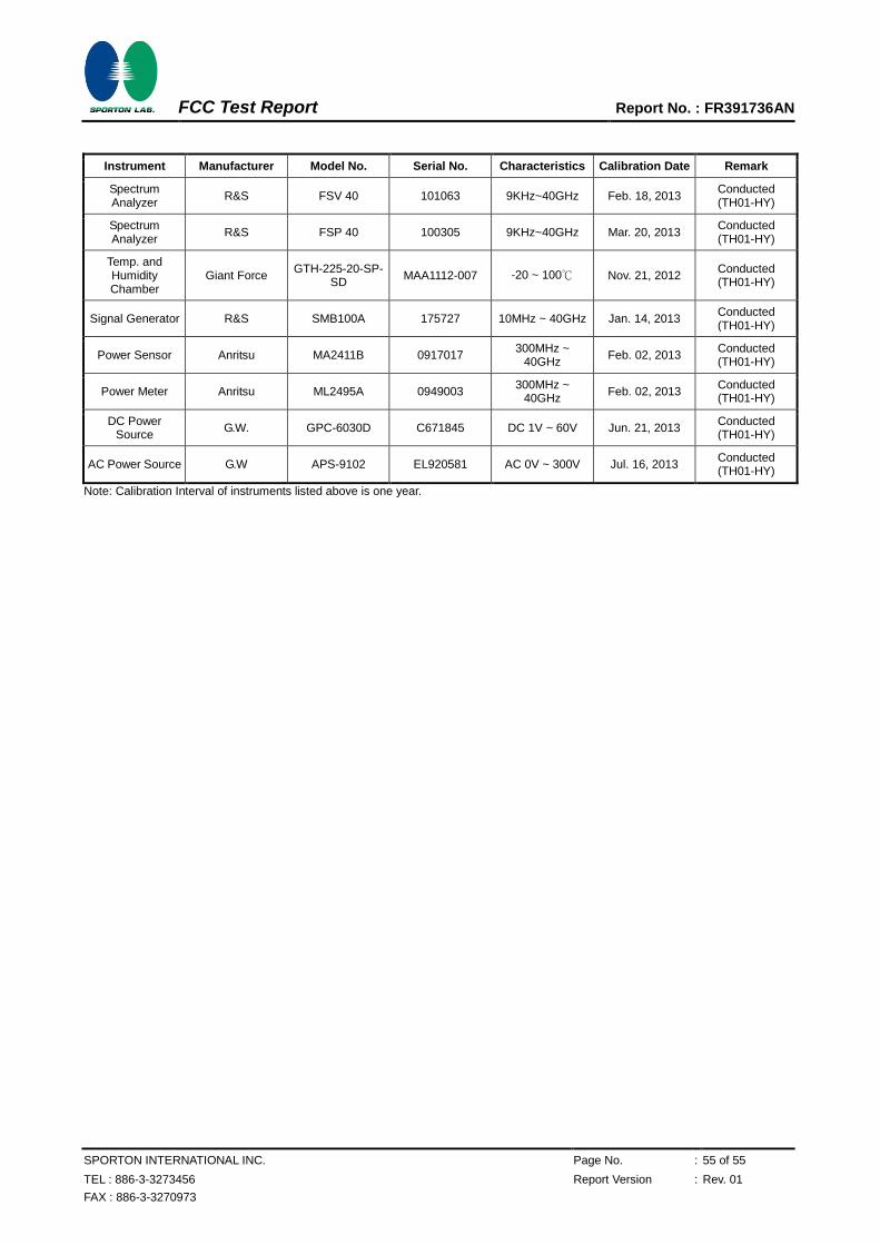
FCC Test Report Report No. : FR391736AN
SPORTON INTERNATIONAL INC. Page No. : 55 of 55
TEL : 886-3-3273456 Report Version : Rev. 01
FAX : 886-3-3270973
Instrument Manufacturer Model No. Serial No. Characteristics Calibration Date Remark
Spectrum Analyzer
R&S FSV 40 101063 9KHz~40GHz Feb. 18, 2013 Conducted (TH01-HY)
Spectrum Analyzer
R&S FSP 40 100305 9KHz~40GHz Mar. 20, 2013 Conducted (TH01-HY)
Temp. and Humidity Chamber
Giant Force GTH-225-20-SP-
SD MAA1112-007 -20 ~ 100℃ Nov. 21, 2012
Conducted (TH01-HY)
Signal Generator R&S SMB100A 175727 10MHz ~ 40GHz Jan. 14, 2013 Conducted (TH01-HY)
Power Sensor Anritsu MA2411B 0917017 300MHz ~
40GHz Feb. 02, 2013
Conducted (TH01-HY)
Power Meter Anritsu ML2495A 0949003 300MHz ~
40GHz Feb. 02, 2013
Conducted (TH01-HY)
DC Power Source
G.W. GPC-6030D C671845 DC 1V ~ 60V Jun. 21, 2013 Conducted (TH01-HY)
AC Power Source G.W APS-9102 EL920581 AC 0V ~ 300V Jul. 16, 2013 Conducted (TH01-HY)
Note: Calibration Interval of instruments listed above is one year.
Test Photos Report No. : FR391736
SPORTON INTERNATIONAL INC. Page No. : A1 of A4
TEL : 886-3-327-3456 Report Version : Rev. 01
FAX : 886-3-327-0973
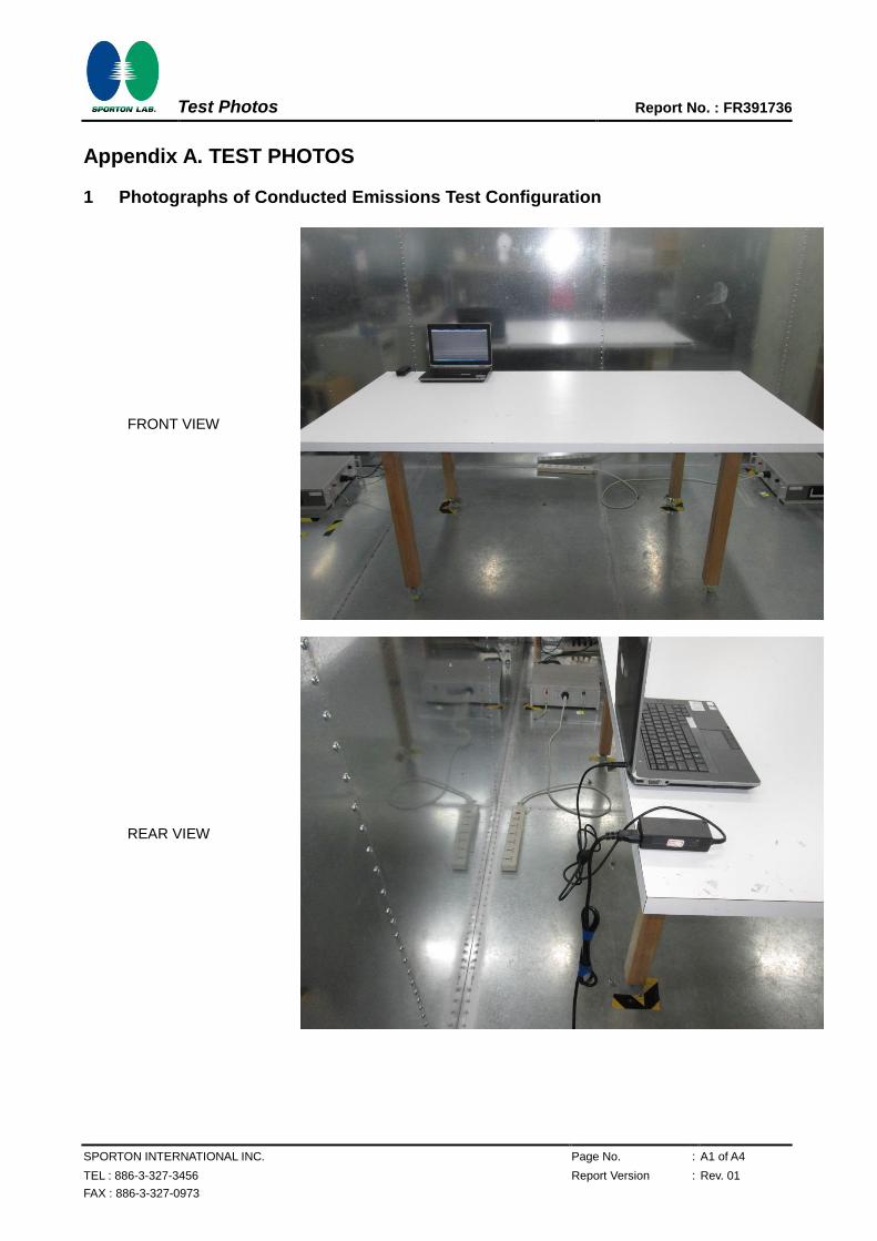
Appendix A. TEST PHOTOS
1 Photographs of Conducted Emissions Test Configuration
FRONT VIEW
REAR VIEW
Test Photos Report No. : FR391736
SPORTON INTERNATIONAL INC. Page No. : A2 of A4
TEL : 886-3-327-3456 Report Version : Rev. 01
FAX : 886-3-327-0973
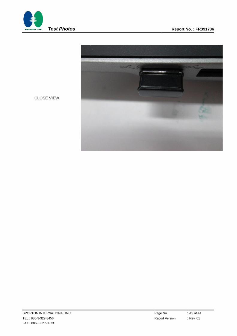
CLOSE VIEW
Test Photos Report No. : FR391736
SPORTON INTERNATIONAL INC. Page No. : A3 of A4
TEL : 886-3-327-3456 Report Version : Rev. 01
FAX : 886-3-327-0973
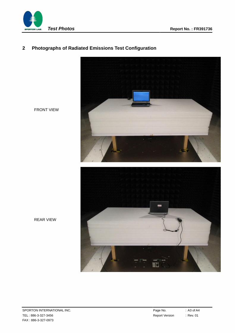
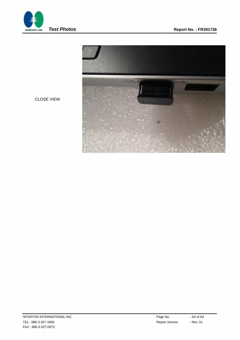
2 Photographs of Radiated Emissions Test Configuration
FRONT VIEW
REAR VIEW
Test Photos Report No. : FR391736
SPORTON INTERNATIONAL INC. Page No. : A4 of A4
TEL : 886-3-327-3456 Report Version : Rev. 01
FAX : 886-3-327-0973
CLOSE VIEW