Embed Size (px)
Citation preview
FCC DFS Test Report Report No. : FZ7N1336
SPORTON INTERNATIONAL INC. Page No. : 2 of 25
TEL : 886-3-327-3456 Report Version : Rev. 01
FAX : 886-3-327-0973 Issued Date : Jan. 15, 2018
FCC ID : PPQ-WCBN3510A Report Template No.: HE1-D2 Ver1.1
Table of Contents 1 GENERAL DESCRIPTION .................................................................................................................... 5
1.1 Information .............................................................................................................................................. 5 1.2 Support Equipment ................................................................................................................................. 9 1.3 Testing Applied Standards ..................................................................................................................... 9 1.4 Testing Location Information .................................................................................................................. 9
2 TEST CONFIGURATION OF EUT....................................................................................................... 10
2.1 Test Channel Frequencies Configuration ............................................................................................. 10
2.2 The Worst Case Measurement Configuration ...................................................................................... 10
3 DYNAMIC FREQUENCY SELECTION (DFS) TEST RESULT ........................................................... 11
3.1 General DFS Information ..................................................................................................................... 11 3.2 Radar Test Waveform Calibration ........................................................................................................ 14 3.3 In-service Monitoring ............................................................................................................................ 20
4 TEST EQUIPMENT AND CALIBRATION DATA ................................................................................ 24
5 MEASUREMENT UNCERTAINTY ...................................................................................................... 25
APPENDIX A. TEST PHOTOS
FCC DFS Test Report Report No. : FZ7N1336
SPORTON INTERNATIONAL INC. Page No. : 3 of 25
TEL : 886-3-327-3456 Report Version : Rev. 01
FAX : 886-3-327-0973 Issued Date : Jan. 15, 2018
FCC ID : PPQ-WCBN3510A Report Template No.: HE1-D2 Ver1.1
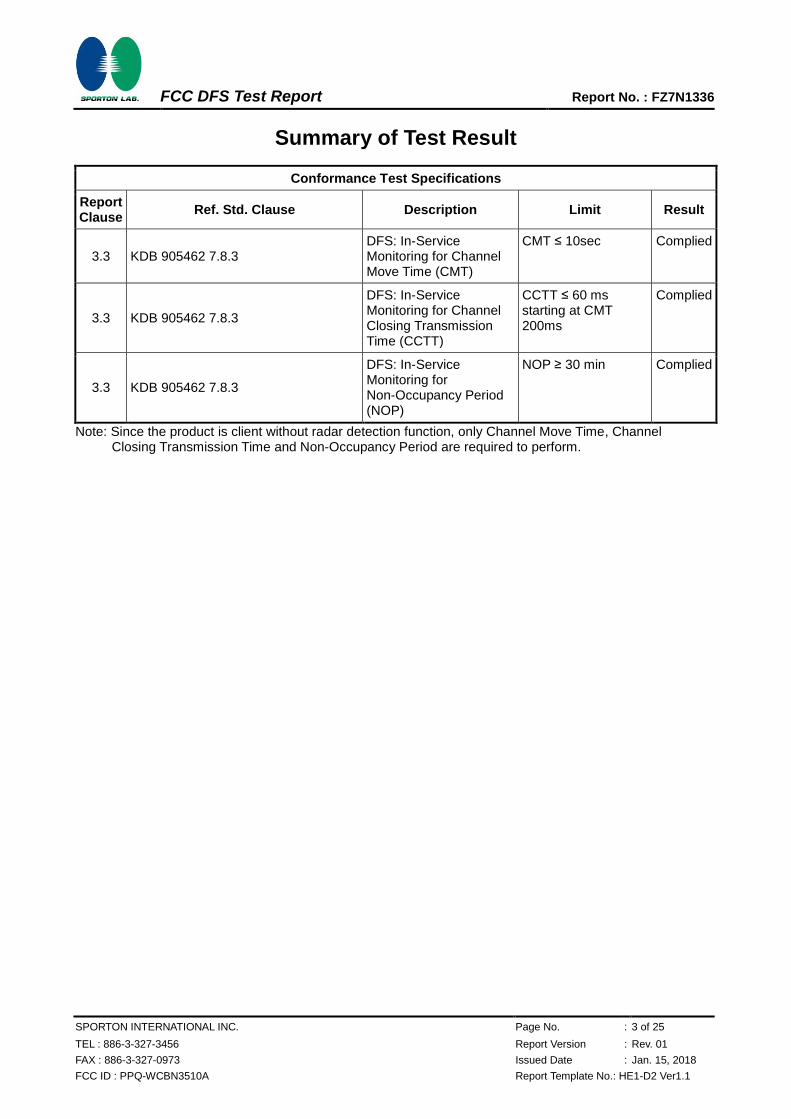
Summary of Test Result
Conformance Test Specifications
Report Clause
Ref. Std. Clause Description Limit Result
3.3 KDB 905462 7.8.3 DFS: In-Service Monitoring for Channel Move Time (CMT)
CMT ≤ 10sec Complied
3.3 KDB 905462 7.8.3
DFS: In-Service Monitoring for Channel Closing Transmission Time (CCTT)
CCTT ≤ 60 ms starting at CMT 200ms
Complied
3.3 KDB 905462 7.8.3
DFS: In-Service Monitoring for Non-Occupancy Period (NOP)
NOP ≥ 30 min Complied
Note: Since the product is client without radar detection function, only Channel Move Time, Channel Closing Transmission Time and Non-Occupancy Period are required to perform.
FCC DFS Test Report Report No. : FZ7N1336
SPORTON INTERNATIONAL INC. Page No. : 4 of 25
TEL : 886-3-327-3456 Report Version : Rev. 01
FAX : 886-3-327-0973 Issued Date : Jan. 15, 2018
FCC ID : PPQ-WCBN3510A Report Template No.: HE1-D2 Ver1.1
Revision History
Report No. Version Description Issued Date
FZ7N1336 Rev. 01 Initial issue of report Jan. 15, 2018
FCC DFS Test Report Report No. : FZ7N1336
SPORTON INTERNATIONAL INC. Page No. : 5 of 25
TEL : 886-3-327-3456 Report Version : Rev. 01
FAX : 886-3-327-0973 Issued Date : Jan. 15, 2018
FCC ID : PPQ-WCBN3510A Report Template No.: HE1-D2 Ver1.1
1 General Description
1.1 Information
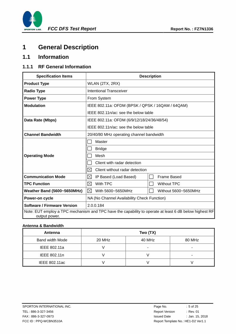
1.1.1 RF General Information
Specification Items Description
Product Type WLAN (2TX, 2RX)
Radio Type Intentional Transceiver
Power Type From System
Modulation IEEE 802.11a: OFDM (BPSK / QPSK / 16QAM / 64QAM)
IEEE 802.11n/ac: see the below table
Data Rate (Mbps) IEEE 802.11a: OFDM (6/9/12/18/24/36/48/54)
IEEE 802.11n/ac: see the below table
Channel Bandwidth 20/40/80 MHz operating channel bandwidth
Operating Mode
Master
Bridge
Mesh
Client with radar detection
Client without radar detection
Communication Mode IP Based (Load Based) Frame Based
TPC Function With TPC Without TPC
Weather Band (5600~5650MHz) With 5600~5650MHz Without 5600~5650MHz
Power-on cycle NA (No Channel Availability Check Function)
Software / Firmware Version 2.0.0.184
Note: EUT employ a TPC mechanism and TPC have the capability to operate at least 6 dB below highest RF output power.
Antenna & Bandwidth
Antenna Two (TX)
Band width Mode 20 MHz 40 MHz 80 MHz
IEEE 802.11a V - -
IEEE 802.11n V V -
IEEE 802.11ac V V V
FCC DFS Test Report Report No. : FZ7N1336
SPORTON INTERNATIONAL INC. Page No. : 6 of 25
TEL : 886-3-327-3456 Report Version : Rev. 01
FAX : 886-3-327-0973 Issued Date : Jan. 15, 2018
FCC ID : PPQ-WCBN3510A Report Template No.: HE1-D2 Ver1.1
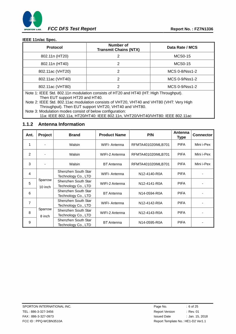
IEEE 11n/ac Spec.
Protocol Number of
Transmit Chains (NTX) Data Rate / MCS
802.11n (HT20) 2 MCS0-15
802.11n (HT40) 2 MCS0-15
802.11ac (VHT20) 2 MCS 0-8/Nss1-2
802.11ac (VHT40) 2 MCS 0-9/Nss1-2
802.11ac (VHT80) 2 MCS 0-9/Nss1-2
Note 1: IEEE Std. 802.11n modulation consists of HT20 and HT40 (HT: High Throughput). Then EUT support HT20 and HT40.
Note 2: IEEE Std. 802.11ac modulation consists of VHT20, VHT40 and VHT80 (VHT: Very High Throughput). Then EUT support VHT20, VHT40 and VHT80.
Note 3: Modulation modes consist of below configuration: 11a: IEEE 802.11a, HT20/HT40: IEEE 802.11n, VHT20/VHT40/VHT80: IEEE 802.11ac
1.1.2 Antenna Information
Ant. Project Brand Product Name P/N Antenna
Type Connector
1 - Walsin WIFI- Antenna RFMTA401020IMLB701 PIFA Mini i-Pex
2 - Walsin WIFI-2 Antenna RFMTA401020IMLB701 PIFA Mini i-Pex
3 - Walsin BT Antenna RFMTA401020IMLB701 PIFA Mini i-Pex
4
Sparrow
10 inch
Shenzhen South Star
Technology Co., LTD WIFI- Antenna N12-4140-R0A PIFA -
5 Shenzhen South Star
Technology Co., LTD WIFI-2 Antenna N12-4141-R0A PIFA -
6 Shenzhen South Star
Technology Co., LTD BT Antenna N14-0594-R0A PIFA -
7
Sparrow
8 inch
Shenzhen South Star
Technology Co., LTD WIFI- Antenna N12-4142-R0A PIFA -
8 Shenzhen South Star
Technology Co., LTD WIFI-2 Antenna N12-4143-R0A PIFA -
9 Shenzhen South Star
Technology Co., LTD BT Antenna N14-0595-R0A PIFA -
FCC DFS Test Report Report No. : FZ7N1336
SPORTON INTERNATIONAL INC. Page No. : 7 of 25
TEL : 886-3-327-3456 Report Version : Rev. 01
FAX : 886-3-327-0973 Issued Date : Jan. 15, 2018
FCC ID : PPQ-WCBN3510A Report Template No.: HE1-D2 Ver1.1
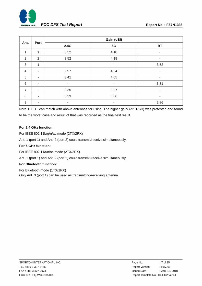
Ant. Port Gain (dBi)
2.4G 5G BT
1 1 3.52 4.18 -
2 2 3.52 4.18 -
3 1 - - 3.52
4 - 2.97 4.04 -
5 - 3.41 4.05 -
6 - - - 3.31
7 - 3.35 3.97 -
8 - 3.33 3.86 -
9 - - - 2.86
Note 1: EUT can match with above antennas for using. The higher gain(Ant. 1/2/3) was pretested and found
to be the worst case and result of that was recorded as the final test result.
For 2.4 GHz function:
For IEEE 802.11b/g/n/ac mode (2TX/2RX)
Ant. 1 (port 1) and Ant. 2 (port 2) could transmit/receive simultaneously.
For 5 GHz function:
For IEEE 802.11a/n/ac mode (2TX/2RX)
Ant. 1 (port 1) and Ant. 2 (port 2) could transmit/receive simultaneously.
For Bluetooth function:
For Bluetooth mode (1TX/1RX)
Only Ant. 3 (port 1) can be used as transmitting/receiving antenna.
FCC DFS Test Report Report No. : FZ7N1336
SPORTON INTERNATIONAL INC. Page No. : 8 of 25
TEL : 886-3-327-3456 Report Version : Rev. 01
FAX : 886-3-327-0973 Issued Date : Jan. 15, 2018
FCC ID : PPQ-WCBN3510A Report Template No.: HE1-D2 Ver1.1
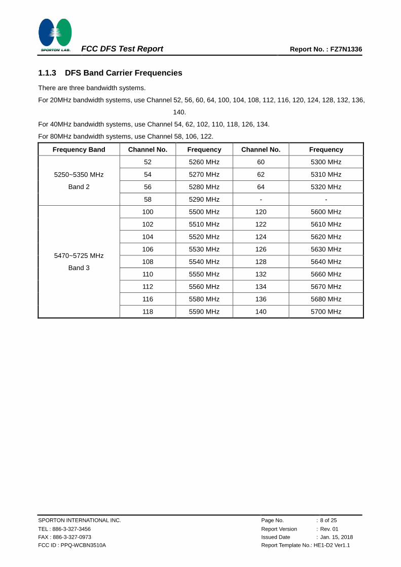
1.1.3 DFS Band Carrier Frequencies
There are three bandwidth systems.
For 20MHz bandwidth systems, use Channel 52, 56, 60, 64, 100, 104, 108, 112, 116, 120, 124, 128, 132, 136,
140.
For 40MHz bandwidth systems, use Channel 54, 62, 102, 110, 118, 126, 134.
For 80MHz bandwidth systems, use Channel 58, 106, 122.
Frequency Band Channel No. Frequency Channel No. Frequency
5250~5350 MHz
Band 2
52 5260 MHz 60 5300 MHz
54 5270 MHz 62 5310 MHz
56 5280 MHz 64 5320 MHz
58 5290 MHz - -
5470~5725 MHz
Band 3
100 5500 MHz 120 5600 MHz
102 5510 MHz 122 5610 MHz
104 5520 MHz 124 5620 MHz
106 5530 MHz 126 5630 MHz
108 5540 MHz 128 5640 MHz
110 5550 MHz 132 5660 MHz
112 5560 MHz 134 5670 MHz
116 5580 MHz 136 5680 MHz
118 5590 MHz 140 5700 MHz
FCC DFS Test Report Report No. : FZ7N1336
SPORTON INTERNATIONAL INC. Page No. : 9 of 25
TEL : 886-3-327-3456 Report Version : Rev. 01
FAX : 886-3-327-0973 Issued Date : Jan. 15, 2018
FCC ID : PPQ-WCBN3510A Report Template No.: HE1-D2 Ver1.1
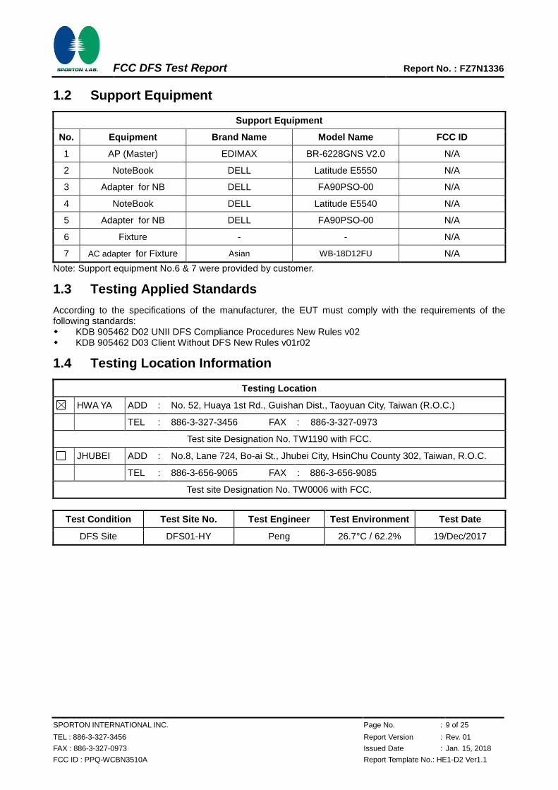
1.2 Support Equipment
Support Equipment
No. Equipment Brand Name Model Name FCC ID
1 AP (Master) EDIMAX BR-6228GNS V2.0 N/A
2 NoteBook DELL Latitude E5550 N/A
3 Adapter for NB DELL FA90PSO-00 N/A
4 NoteBook DELL Latitude E5540 N/A
5 Adapter for NB DELL FA90PSO-00 N/A
6 Fixture - - N/A
7 AC adapter for Fixture Asian WB-18D12FU N/A
Note: Support equipment No.6 & 7 were provided by customer.
1.3 Testing Applied Standards
According to the specifications of the manufacturer, the EUT must comply with the requirements of the following standards: KDB 905462 D02 UNII DFS Compliance Procedures New Rules v02 KDB 905462 D03 Client Without DFS New Rules v01r02
1.4 Testing Location Information
Testing Location
HWA YA ADD : No. 52, Huaya 1st Rd., Guishan Dist., Taoyuan City, Taiwan (R.O.C.)
TEL : 886-3-327-3456 FAX : 886-3-327-0973
Test site Designation No. TW1190 with FCC.
JHUBEI ADD : No.8, Lane 724, Bo-ai St., Jhubei City, HsinChu County 302, Taiwan, R.O.C.
TEL : 886-3-656-9065 FAX : 886-3-656-9085
Test site Designation No. TW0006 with FCC.
Test Condition Test Site No. Test Engineer Test Environment Test Date
DFS Site DFS01-HY Peng 26.7°C / 62.2% 19/Dec/2017
FCC DFS Test Report Report No. : FZ7N1336
SPORTON INTERNATIONAL INC. Page No. : 10 of 25
TEL : 886-3-327-3456 Report Version : Rev. 01
FAX : 886-3-327-0973 Issued Date : Jan. 15, 2018
FCC ID : PPQ-WCBN3510A Report Template No.: HE1-D2 Ver1.1
2 Test Configuration of EUT
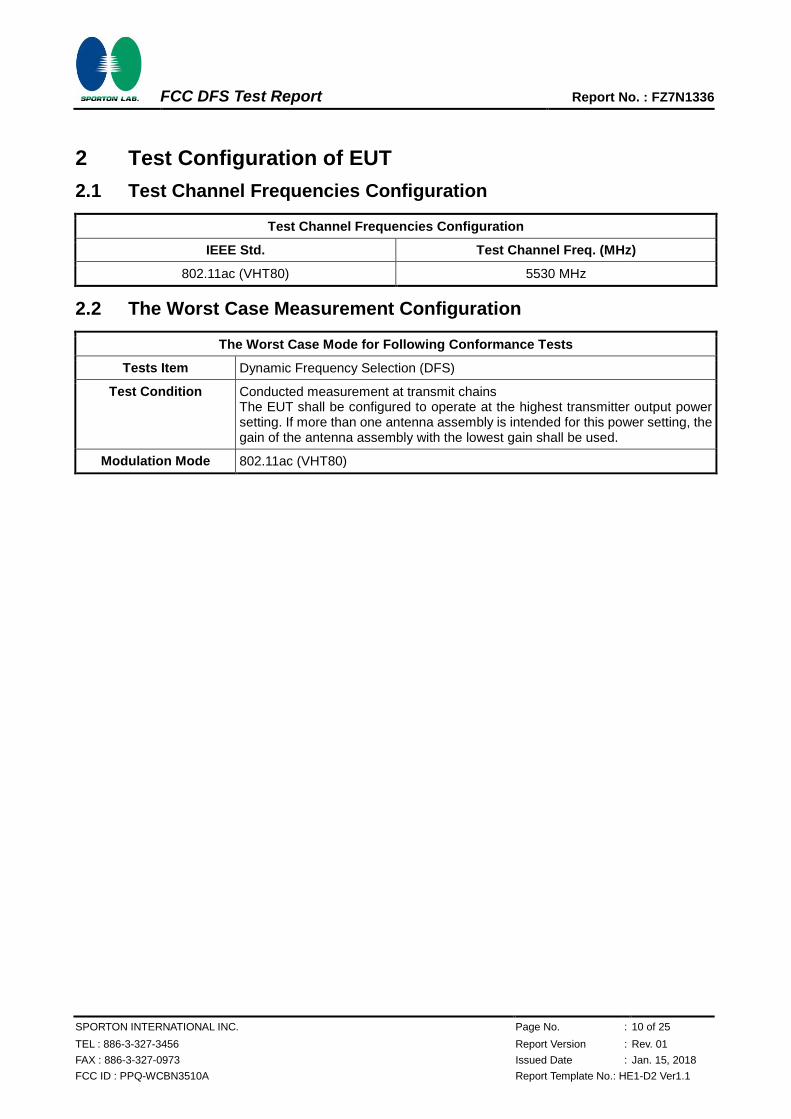
2.1 Test Channel Frequencies Configuration
Test Channel Frequencies Configuration
IEEE Std. Test Channel Freq. (MHz)
802.11ac (VHT80) 5530 MHz
2.2 The Worst Case Measurement Configuration
The Worst Case Mode for Following Conformance Tests
Tests Item Dynamic Frequency Selection (DFS)
Test Condition Conducted measurement at transmit chains The EUT shall be configured to operate at the highest transmitter output power setting. If more than one antenna assembly is intended for this power setting, the gain of the antenna assembly with the lowest gain shall be used.
Modulation Mode 802.11ac (VHT80)
FCC DFS Test Report Report No. : FZ7N1336
SPORTON INTERNATIONAL INC. Page No. : 11 of 25
TEL : 886-3-327-3456 Report Version : Rev. 01
FAX : 886-3-327-0973 Issued Date : Jan. 15, 2018
FCC ID : PPQ-WCBN3510A Report Template No.: HE1-D2 Ver1.1
3 Dynamic Frequency Selection (DFS) Test Result
3.1 General DFS Information
3.1.1 DFS Parameters
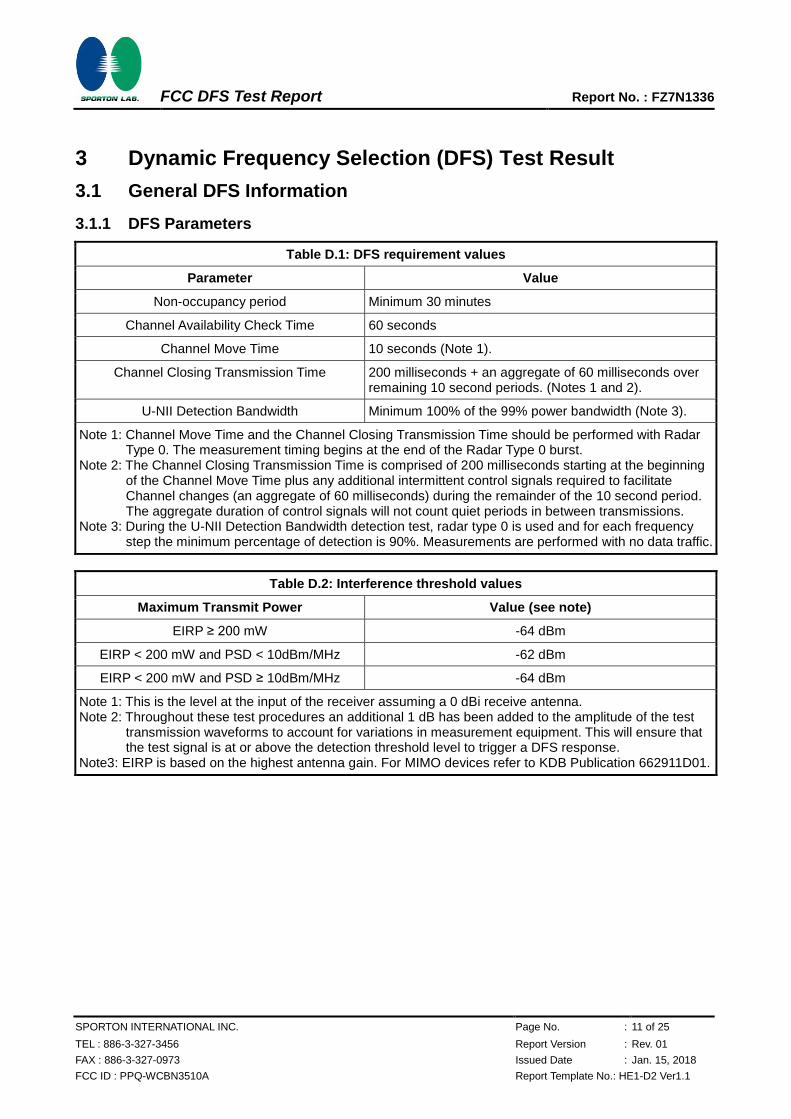
Table D.1: DFS requirement values
Parameter Value
Non-occupancy period Minimum 30 minutes
Channel Availability Check Time 60 seconds
Channel Move Time 10 seconds (Note 1).
Channel Closing Transmission Time 200 milliseconds + an aggregate of 60 milliseconds over remaining 10 second periods. (Notes 1 and 2).
U-NII Detection Bandwidth Minimum 100% of the 99% power bandwidth (Note 3).
Note 1: Channel Move Time and the Channel Closing Transmission Time should be performed with Radar Type 0. The measurement timing begins at the end of the Radar Type 0 burst.
Note 2: The Channel Closing Transmission Time is comprised of 200 milliseconds starting at the beginning of the Channel Move Time plus any additional intermittent control signals required to facilitate Channel changes (an aggregate of 60 milliseconds) during the remainder of the 10 second period. The aggregate duration of control signals will not count quiet periods in between transmissions.
Note 3: During the U-NII Detection Bandwidth detection test, radar type 0 is used and for each frequency step the minimum percentage of detection is 90%. Measurements are performed with no data traffic.
Table D.2: Interference threshold values
Maximum Transmit Power Value (see note)
EIRP ≥ 200 mW -64 dBm
EIRP < 200 mW and PSD < 10dBm/MHz -62 dBm
EIRP < 200 mW and PSD ≥ 10dBm/MHz -64 dBm
Note 1: This is the level at the input of the receiver assuming a 0 dBi receive antenna. Note 2: Throughout these test procedures an additional 1 dB has been added to the amplitude of the test
transmission waveforms to account for variations in measurement equipment. This will ensure that the test signal is at or above the detection threshold level to trigger a DFS response.
Note3: EIRP is based on the highest antenna gain. For MIMO devices refer to KDB Publication 662911D01.
FCC DFS Test Report Report No. : FZ7N1336
SPORTON INTERNATIONAL INC. Page No. : 12 of 25
TEL : 886-3-327-3456 Report Version : Rev. 01
FAX : 886-3-327-0973 Issued Date : Jan. 15, 2018
FCC ID : PPQ-WCBN3510A Report Template No.: HE1-D2 Ver1.1
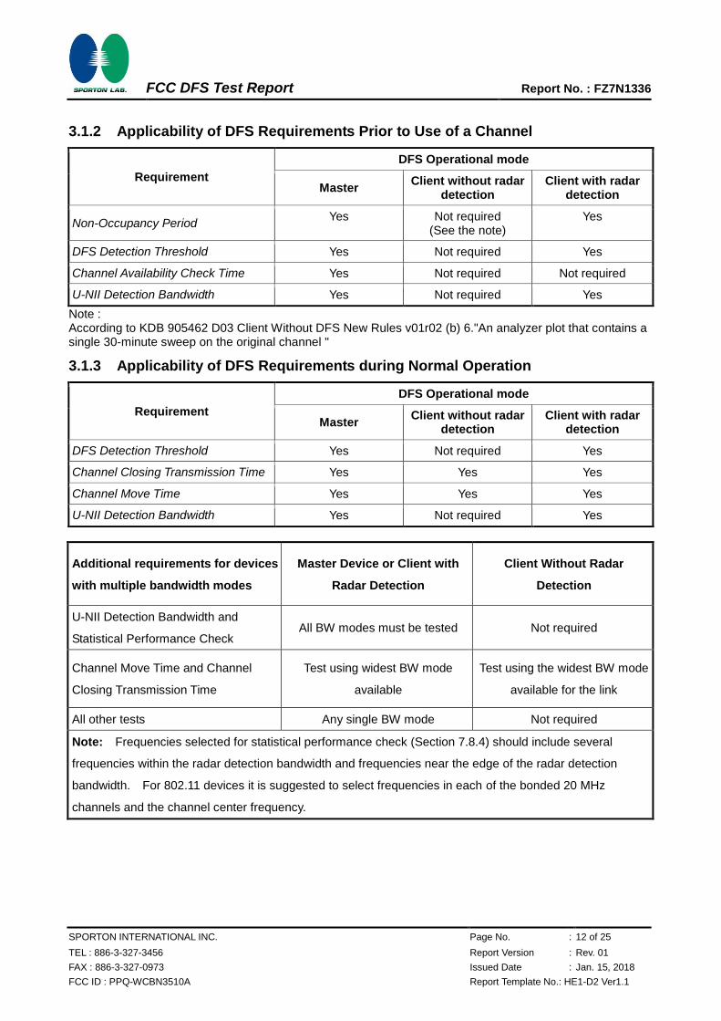
3.1.2 Applicability of DFS Requirements Prior to Use of a Channel
Requirement
DFS Operational mode
Master Client without radar
detection Client with radar
detection
Non-Occupancy Period Yes Not required
(See the note) Yes
DFS Detection Threshold Yes Not required Yes
Channel Availability Check Time Yes Not required Not required
U-NII Detection Bandwidth Yes Not required Yes
Note : According to KDB 905462 D03 Client Without DFS New Rules v01r02 (b) 6."An analyzer plot that contains a single 30-minute sweep on the original channel "
3.1.3 Applicability of DFS Requirements during Normal Operation
Requirement
DFS Operational mode
Master Client without radar
detection Client with radar
detection
DFS Detection Threshold Yes Not required Yes
Channel Closing Transmission Time Yes Yes Yes
Channel Move Time Yes Yes Yes
U-NII Detection Bandwidth Yes Not required Yes
Additional requirements for devices
with multiple bandwidth modes
Master Device or Client with
Radar Detection
Client Without Radar
Detection
U-NII Detection Bandwidth and
Statistical Performance Check All BW modes must be tested Not required
Channel Move Time and Channel
Closing Transmission Time
Test using widest BW mode
available
Test using the widest BW mode
available for the link
All other tests Any single BW mode Not required
Note: Frequencies selected for statistical performance check (Section 7.8.4) should include several
frequencies within the radar detection bandwidth and frequencies near the edge of the radar detection
bandwidth. For 802.11 devices it is suggested to select frequencies in each of the bonded 20 MHz
channels and the channel center frequency.
FCC DFS Test Report Report No. : FZ7N1336
SPORTON INTERNATIONAL INC. Page No. : 13 of 25
TEL : 886-3-327-3456 Report Version : Rev. 01
FAX : 886-3-327-0973 Issued Date : Jan. 15, 2018
FCC ID : PPQ-WCBN3510A Report Template No.: HE1-D2 Ver1.1
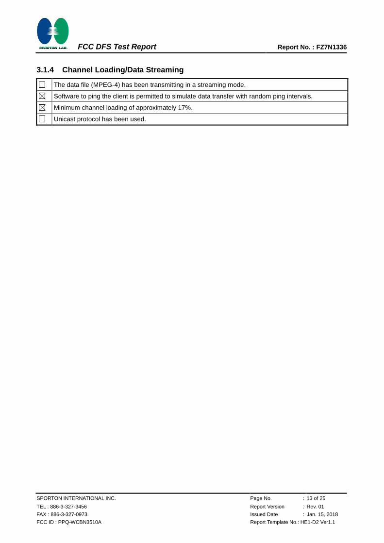
3.1.4 Channel Loading/Data Streaming
The data file (MPEG-4) has been transmitting in a streaming mode.
Software to ping the client is permitted to simulate data transfer with random ping intervals.
Minimum channel loading of approximately 17%.
Unicast protocol has been used.
FCC DFS Test Report Report No. : FZ7N1336
SPORTON INTERNATIONAL INC. Page No. : 14 of 25
TEL : 886-3-327-3456 Report Version : Rev. 01
FAX : 886-3-327-0973 Issued Date : Jan. 15, 2018
FCC ID : PPQ-WCBN3510A Report Template No.: HE1-D2 Ver1.1
3.2 Radar Test Waveform Calibration
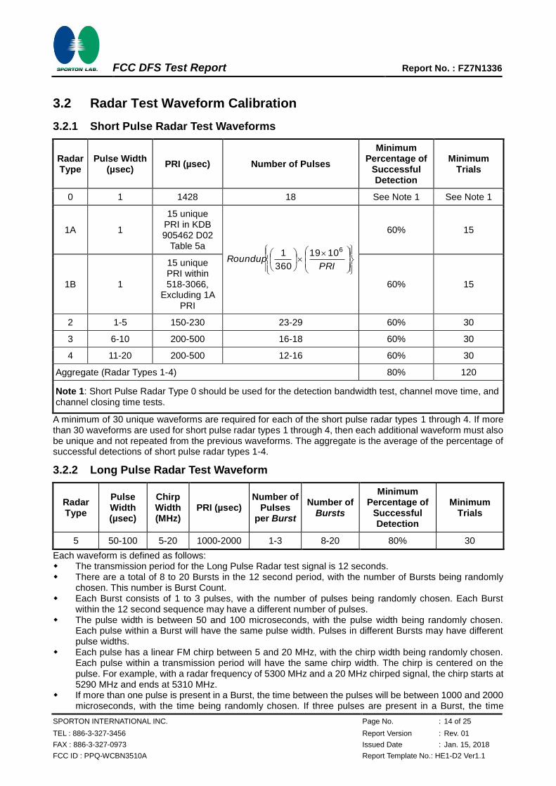
3.2.1 Short Pulse Radar Test Waveforms
Radar Type
Pulse Width (µsec)
PRI (µsec) Number of Pulses
Minimum Percentage of
Successful Detection
Minimum Trials
0 1 1428 18 See Note 1 See Note 1
1A 1
15 unique PRI in KDB 905462 D02
Table 5a
PRIRoundup
61019
360
1
60% 15
1B 1
15 unique PRI within 518-3066,
Excluding 1A PRI
60% 15
2 1-5 150-230 23-29 60% 30
3 6-10 200-500 16-18 60% 30
4 11-20 200-500 12-16 60% 30
Aggregate (Radar Types 1-4) 80% 120
Note 1: Short Pulse Radar Type 0 should be used for the detection bandwidth test, channel move time, and channel closing time tests.
A minimum of 30 unique waveforms are required for each of the short pulse radar types 1 through 4. If more than 30 waveforms are used for short pulse radar types 1 through 4, then each additional waveform must also be unique and not repeated from the previous waveforms. The aggregate is the average of the percentage of successful detections of short pulse radar types 1-4.
3.2.2 Long Pulse Radar Test Waveform
Radar Type
Pulse Width (µsec)
Chirp Width (MHz)
PRI (µsec) Number of
Pulses per Burst
Number of Bursts
Minimum Percentage of
Successful Detection
Minimum Trials
5 50-100 5-20 1000-2000 1-3 8-20 80% 30
Each waveform is defined as follows: The transmission period for the Long Pulse Radar test signal is 12 seconds. There are a total of 8 to 20 Bursts in the 12 second period, with the number of Bursts being randomly
chosen. This number is Burst Count. Each Burst consists of 1 to 3 pulses, with the number of pulses being randomly chosen. Each Burst
within the 12 second sequence may have a different number of pulses. The pulse width is between 50 and 100 microseconds, with the pulse width being randomly chosen.
Each pulse within a Burst will have the same pulse width. Pulses in different Bursts may have different pulse widths.
Each pulse has a linear FM chirp between 5 and 20 MHz, with the chirp width being randomly chosen. Each pulse within a transmission period will have the same chirp width. The chirp is centered on the pulse. For example, with a radar frequency of 5300 MHz and a 20 MHz chirped signal, the chirp starts at 5290 MHz and ends at 5310 MHz.
If more than one pulse is present in a Burst, the time between the pulses will be between 1000 and 2000 microseconds, with the time being randomly chosen. If three pulses are present in a Burst, the time
FCC DFS Test Report Report No. : FZ7N1336
SPORTON INTERNATIONAL INC. Page No. : 15 of 25
TEL : 886-3-327-3456 Report Version : Rev. 01
FAX : 886-3-327-0973 Issued Date : Jan. 15, 2018
FCC ID : PPQ-WCBN3510A Report Template No.: HE1-D2 Ver1.1
between the first and second pulses is chosen independently of the time between the second and third pulses.
The 12 second transmission period is divided into even intervals. The number of intervals is equal to Burst Count. Each interval is of length (12,000,000 / Burst Count) microseconds. Each interval contains one Burst. The start time for the Burst, relative to the beginning of the interval, is between 1 and [(12,000,000 / Burst Count) – (Total Burst Length) + (One Random PRI Interval)] microseconds, with the start time being randomly chosen. The step interval for the start time is 1 microsecond. The start time for each Burst is chosen independently.
3.2.3 Frequency Hopping Radar Test Waveform
Radar Type
Pulse Width (µsec)
PRI (µsec)
Pulses per Hop
Hopping Rate (kHz)
Hopping Sequence
Length (ms)
Minimum Percentage of
Successful Detection
Minimum Trials
6 1 333 9 0.333 300 70% 30
The FCC Type 6 waveform uses a static waveform with 100 bursts in the instruments ARB. In addition, the RF list mode is operated with a list containing 100 frequencies from a randomly generated list and it had be ensured that at least one of the random frequencies falls into the UNII Detection Bandwidth of the DUT. Each burst from the waveform file initiates a trigger pulse at the beginning that switches the RF list from one item to the next one.
3.2.4 DFS Threshold Level
DFS Threshold Level
DFS Threshold level: -63 dBm at the antenna connector
in front of the antenna
The Interference Radar Detection Threshold Level is is -64 dBm + 0 [dBi] + 1 dB = -63 dBm. That had been taken into account the output power range and antenna gain.
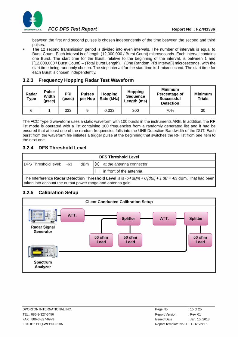
3.2.5 Calibration Setup
Client Conducted Calibration Setup
FCC DFS Test Report Report No. : FZ7N1336
SPORTON INTERNATIONAL INC. Page No. : 16 of 25
TEL : 886-3-327-3456 Report Version : Rev. 01
FAX : 886-3-327-0973 Issued Date : Jan. 15, 2018
FCC ID : PPQ-WCBN3510A Report Template No.: HE1-D2 Ver1.1
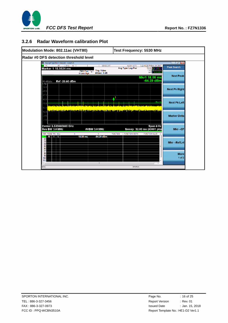
3.2.6 Radar Waveform calibration Plot
Modulation Mode: 802.11ac (VHT80) Test Frequency: 5530 MHz
Radar #0 DFS detection threshold level
FCC DFS Test Report Report No. : FZ7N1336
SPORTON INTERNATIONAL INC. Page No. : 17 of 25
TEL : 886-3-327-3456 Report Version : Rev. 01
FAX : 886-3-327-0973 Issued Date : Jan. 15, 2018
FCC ID : PPQ-WCBN3510A Report Template No.: HE1-D2 Ver1.1
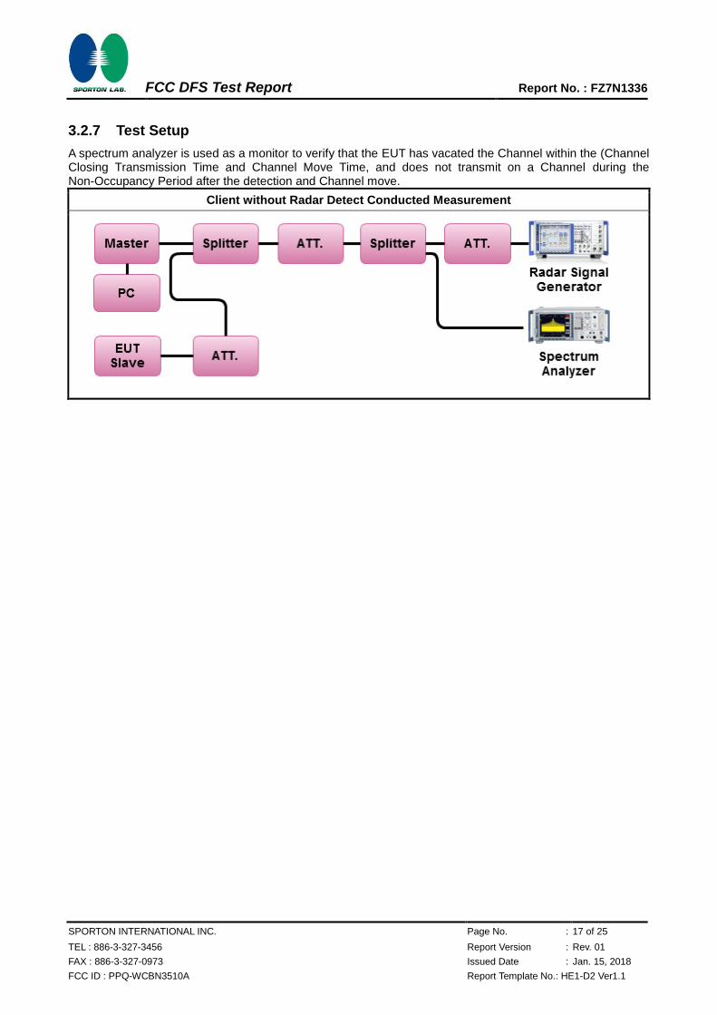
3.2.7 Test Setup
A spectrum analyzer is used as a monitor to verify that the EUT has vacated the Channel within the (Channel Closing Transmission Time and Channel Move Time, and does not transmit on a Channel during the Non-Occupancy Period after the detection and Channel move.
Client without Radar Detect Conducted Measurement
FCC DFS Test Report Report No. : FZ7N1336
SPORTON INTERNATIONAL INC. Page No. : 18 of 25
TEL : 886-3-327-3456 Report Version : Rev. 01
FAX : 886-3-327-0973 Issued Date : Jan. 15, 2018
FCC ID : PPQ-WCBN3510A Report Template No.: HE1-D2 Ver1.1
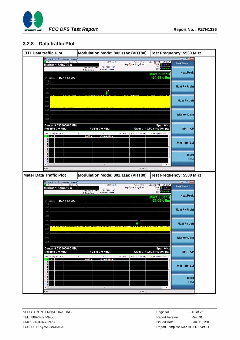
3.2.8 Data traffic Plot
EUT Data traffic Plot Modulation Mode: 802.11ac (VHT80) Test Frequency: 5530 MHz
Mater Data Traffic Plot Modulation Mode: 802.11ac (VHT80) Test Frequency: 5530 MHz
FCC DFS Test Report Report No. : FZ7N1336
SPORTON INTERNATIONAL INC. Page No. : 19 of 25
TEL : 886-3-327-3456 Report Version : Rev. 01
FAX : 886-3-327-0973 Issued Date : Jan. 15, 2018
FCC ID : PPQ-WCBN3510A Report Template No.: HE1-D2 Ver1.1
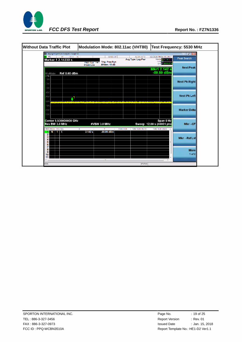
Without Data Traffic Plot Modulation Mode: 802.11ac (VHT80) Test Frequency: 5530 MHz
FCC DFS Test Report Report No. : FZ7N1336
SPORTON INTERNATIONAL INC. Page No. : 20 of 25
TEL : 886-3-327-3456 Report Version : Rev. 01
FAX : 886-3-327-0973 Issued Date : Jan. 15, 2018
FCC ID : PPQ-WCBN3510A Report Template No.: HE1-D2 Ver1.1
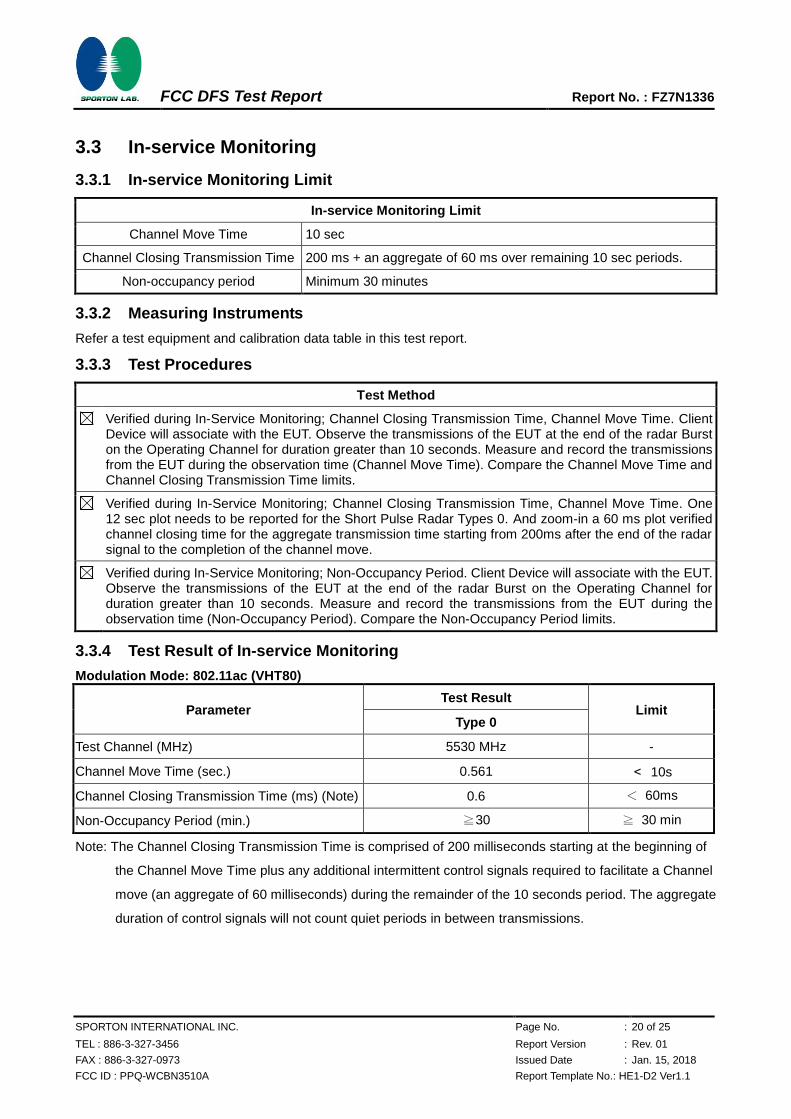
3.3 In-service Monitoring
3.3.1 In-service Monitoring Limit
In-service Monitoring Limit
Channel Move Time 10 sec
Channel Closing Transmission Time 200 ms + an aggregate of 60 ms over remaining 10 sec periods.
Non-occupancy period Minimum 30 minutes
3.3.2 Measuring Instruments
Refer a test equipment and calibration data table in this test report.
3.3.3 Test Procedures
Test Method
Verified during In-Service Monitoring; Channel Closing Transmission Time, Channel Move Time. Client Device will associate with the EUT. Observe the transmissions of the EUT at the end of the radar Burst on the Operating Channel for duration greater than 10 seconds. Measure and record the transmissions from the EUT during the observation time (Channel Move Time). Compare the Channel Move Time and Channel Closing Transmission Time limits.
Verified during In-Service Monitoring; Channel Closing Transmission Time, Channel Move Time. One 12 sec plot needs to be reported for the Short Pulse Radar Types 0. And zoom-in a 60 ms plot verified channel closing time for the aggregate transmission time starting from 200ms after the end of the radar signal to the completion of the channel move.
Verified during In-Service Monitoring; Non-Occupancy Period. Client Device will associate with the EUT. Observe the transmissions of the EUT at the end of the radar Burst on the Operating Channel for duration greater than 10 seconds. Measure and record the transmissions from the EUT during the observation time (Non-Occupancy Period). Compare the Non-Occupancy Period limits.
3.3.4 Test Result of In-service Monitoring
Modulation Mode: 802.11ac (VHT80)
Parameter Test Result
Limit Type 0
Test Channel (MHz) 5530 MHz -
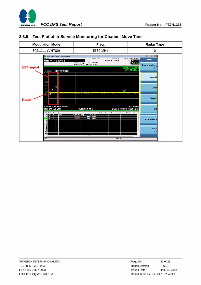
Channel Move Time (sec.) 0.561 < 10s
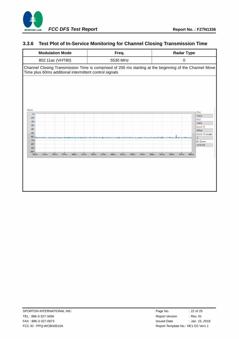
Channel Closing Transmission Time (ms) (Note) 0.6 < 60ms
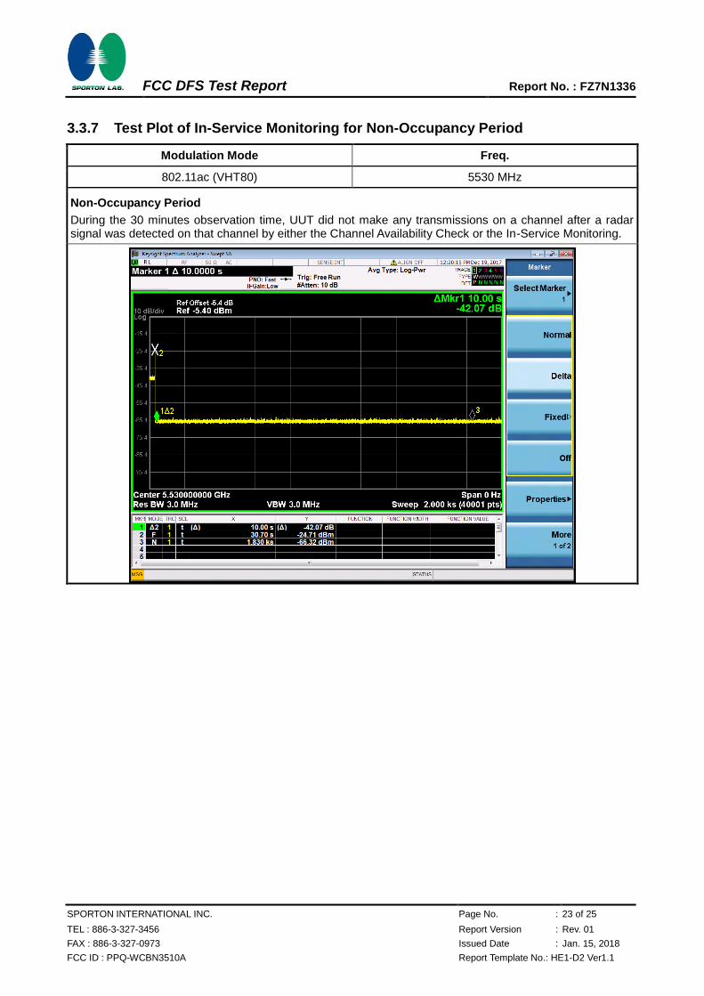
Non-Occupancy Period (min.) ≧30 ≧ 30 min
Note: The Channel Closing Transmission Time is comprised of 200 milliseconds starting at the beginning of
the Channel Move Time plus any additional intermittent control signals required to facilitate a Channel
move (an aggregate of 60 milliseconds) during the remainder of the 10 seconds period. The aggregate
duration of control signals will not count quiet periods in between transmissions.
FCC DFS Test Report Report No. : FZ7N1336
SPORTON INTERNATIONAL INC. Page No. : 21 of 25
TEL : 886-3-327-3456 Report Version : Rev. 01
FAX : 886-3-327-0973 Issued Date : Jan. 15, 2018
FCC ID : PPQ-WCBN3510A Report Template No.: HE1-D2 Ver1.1
3.3.5 Test Plot of In-Service Monitoring for Channel Move Time
Modulation Mode Freq. Radar Type
802.11ac (VHT80) 5530 MHz 0
Radar
EUT signal
FCC DFS Test Report Report No. : FZ7N1336
SPORTON INTERNATIONAL INC. Page No. : 22 of 25
TEL : 886-3-327-3456 Report Version : Rev. 01
FAX : 886-3-327-0973 Issued Date : Jan. 15, 2018
FCC ID : PPQ-WCBN3510A Report Template No.: HE1-D2 Ver1.1
3.3.6 Test Plot of In-Service Monitoring for Channel Closing Transmission Time
Modulation Mode Freq. Radar Type
802.11ac (VHT80) 5530 MHz 0
Channel Closing Transmission Time is comprised of 200 ms starting at the beginning of the Channel Move Time plus 60ms additional intermittent control signals
FCC DFS Test Report Report No. : FZ7N1336
SPORTON INTERNATIONAL INC. Page No. : 23 of 25
TEL : 886-3-327-3456 Report Version : Rev. 01
FAX : 886-3-327-0973 Issued Date : Jan. 15, 2018
FCC ID : PPQ-WCBN3510A Report Template No.: HE1-D2 Ver1.1
3.3.7 Test Plot of In-Service Monitoring for Non-Occupancy Period
Modulation Mode Freq.
802.11ac (VHT80) 5530 MHz
Non-Occupancy Period
During the 30 minutes observation time, UUT did not make any transmissions on a channel after a radar signal was detected on that channel by either the Channel Availability Check or the In-Service Monitoring.
FCC DFS Test Report Report No. : FZ7N1336
SPORTON INTERNATIONAL INC. Page No. : 24 of 25
TEL : 886-3-327-3456 Report Version : Rev. 01
FAX : 886-3-327-0973 Issued Date : Jan. 15, 2018
FCC ID : PPQ-WCBN3510A Report Template No.: HE1-D2 Ver1.1
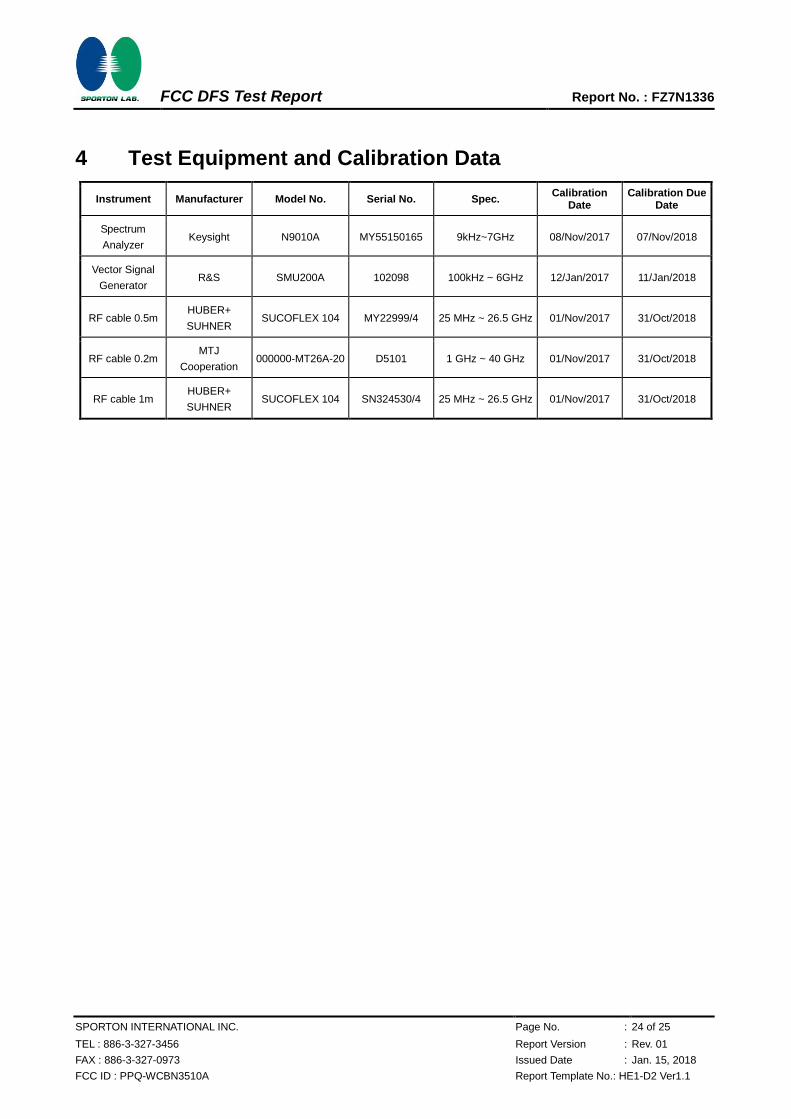
4 Test Equipment and Calibration Data
Instrument Manufacturer Model No. Serial No. Spec. Calibration
Date Calibration Due
Date
Spectrum
Analyzer Keysight N9010A MY55150165 9kHz~7GHz 08/Nov/2017 07/Nov/2018
Vector Signal
Generator R&S SMU200A 102098 100kHz ~ 6GHz 12/Jan/2017 11/Jan/2018
RF cable 0.5m HUBER+
SUHNER SUCOFLEX 104 MY22999/4 25 MHz ~ 26.5 GHz 01/Nov/2017 31/Oct/2018
RF cable 0.2m MTJ
Cooperation 000000-MT26A-20 D5101 1 GHz ~ 40 GHz 01/Nov/2017 31/Oct/2018
RF cable 1m HUBER+
SUHNER SUCOFLEX 104 SN324530/4 25 MHz ~ 26.5 GHz 01/Nov/2017 31/Oct/2018
FCC DFS Test Report Report No. : FZ7N1336
SPORTON INTERNATIONAL INC. Page No. : 25 of 25
TEL : 886-3-327-3456 Report Version : Rev. 01
FAX : 886-3-327-0973 Issued Date : Jan. 15, 2018
FCC ID : PPQ-WCBN3510A Report Template No.: HE1-D2 Ver1.1
5 Measurement Uncertainty
Test Items Uncertainty Remark
Conducted Emission 1.3 dB Confidence levels of 95%