Embed Size (px)
Citation preview
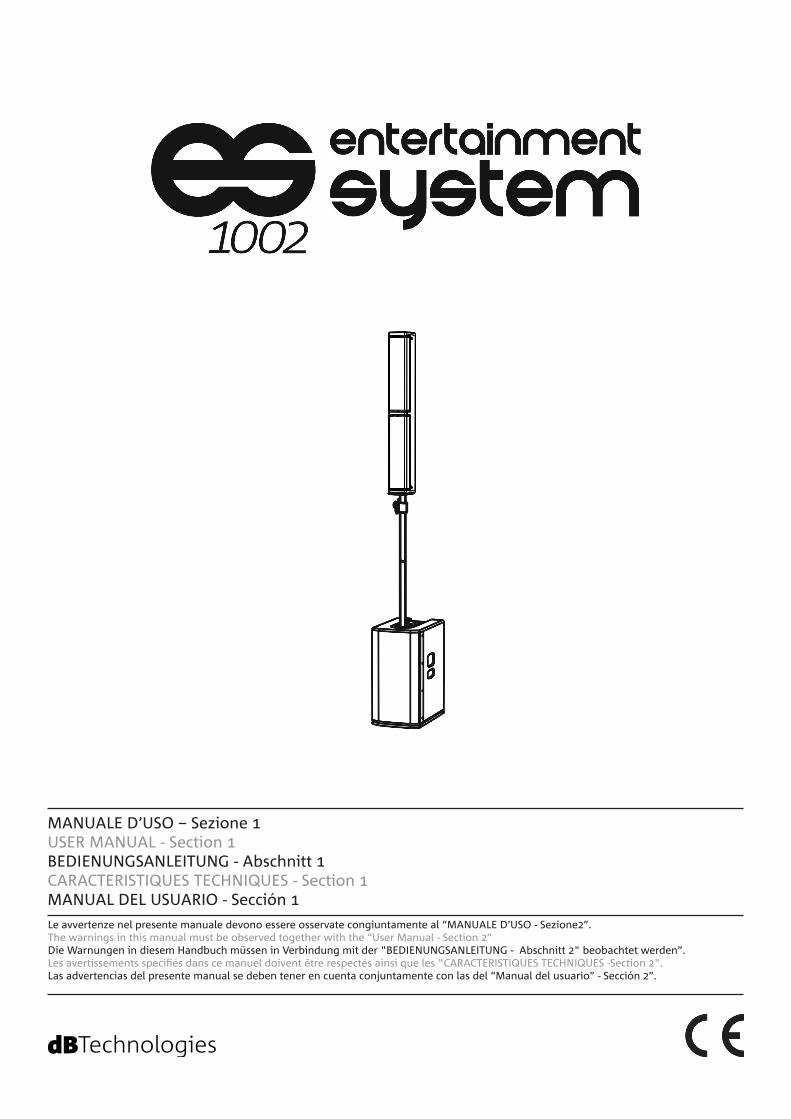
MANUALE D’USO – Sezione 1USER MANUAL - Section 1BEDIENUNGSANLEITUNG - Abschnitt 1CARACTERISTIQUES TECHNIQUES - Section 1 MANUAL DEL USUARIO - Sección 1
Le avvertenze nel presente manuale devono essere osservate congiuntamente al “MANUALE D’USO - Sezione2”.The warnings in this manual must be observed together with the “User Manual - Section 2”Die Warnungen in diesem Handbuch müssen in Verbindung mit der "BEDIENUNGSANLEITUNG - Abschnitt 2" beobachtet werden”.Les avertissements specifiés dans ce manuel doivent être respectés ainsi que les "CARACTERISTIQUES TECHNIQUES -Section 2".Las advertencias del presente manual se deben tener en cuenta conjuntamente con las del “Manual del usuario” - Sección 2”.

EMI CLASSIFICATION
FCC CLASS B STATEMENT ACCORDING TO TITLE 47, CHAPTER I, SUBCHAPTER A, PART 15, SUBPART B
According to the standards EN 55103 this equipment is designed and suitable to operate in E3 (or lower E2, E1) Electromagnetic environments.
This equipment has been tested and found to comply with the limits for a Class B digital device, pursuant to part 15 of the FCC Rules. These limits are designed to provide reasonable protection against harmful interference in a residential installation. This equipment generates, uses and can radiate radio frequency energy and, if not installed and used in accordance with the instructions, may cause harmful interference to radio communications. However, there is no guarantee that interference will not occur in a particular installation. If this equipment does cause harmful interference to radio or television reception, which can be determined by turning the equipment off and on, the user is encouraged to try to correct the interference by one or more of the following measures:
—Reorient or relocate the receiving antenna.
—Increase the separation between the equipment and receiver.
—Connect the equipment into an outlet on a circuit different from that to which the receiver is connected.
—Consult the dealer or an experienced radio/TV technician for help.
Make sure that the loudspeaker is securely installed in a stable position to avoid any injuries or damages to persons or properties. For safety reasons di not place one loudspeaker on top of another without proper fastening systems. Before hanging the loudspeaker check all the components for damages, deformations, missing or damaged parts that may compromise safety during installation. If you use the loudspeakers outdoor avoid spots exposed to bad weather conditions.Contact dBTechnologies for accessories to be used with the speakers. dBTechnologies will not accept any responsibility for damages caused by inappropiate accessories or additional devices.
WARNING
Changes or modifications not expressly approved by the party responsible for compliance could void the user’s authority to operate the equipment.
2
ES-1002 Cod. 420120265 REV. 1.0
ATTENTION !
IMPORTANT SAFETY INSTRUCTIONS:
1. Read these instructions2. Keep these instructions.3. Heed all warnings.4. Follow all instructions.5. Do not use this apparatus near water.6. Clean only with dry cloth.7. Do not block any ventilation openings. Install in accordance with the manufacturer’s instructions.8. Do not install near any heat sources such as radiators, heat registers, stoves, or other apparatus (including
amplifiers) that produce heat.9. Do not defeat the safety purpose of the polarized or grounding-type plug. A polarazied plug has two blades
with one wider than the other. A grounding type plug has two blades and a third grounding prong. The wide blade or the third prong are provided for your safety. If the provided plug does not fit into your outlet, consult an electrician for replacement of the obsolete outlet.
10. Protect the power cord from being walked on or pinched particularly at plugs, convenience receptacles, and the point where they exit from the apparatus.
11. Only use attachements/accessories specified by the manufacturer.
12. Use only with the cart, stand tripod, bracket, or table specified by the manufacturer, or sold with the apparatus. When a cart is used, use caution, when moving the cart/apparatus combination to avoid injury from tip-over.
13. Unplug this apparatus during lightning storms or when unused for long periods of time.14. Refer all servicing to qualified service personnel. Servicing is required when the apparatus has benn damaged
in any way, such as power-supply cord or plug is damaged, liquid has benn spilled or objects have fallen into the apparatusm the apparatus has been exposed to rain or moisture, does not operate normally, or has been dropped.
• Never remove the product's front protection mesh.In order to prevent electric shock hazard, in the event of accidental damage or replacement of the protection mesh (which must be carried out by a service center), disconnect the power supply immediately.Do not connect to the power supply while the mesh has been removed.
• Ne pas déposer la grille frontale de protection du produit. Pour prévenir le risque de choc ou dé-charge électrique, en cas d'endommagement accidentel ou de remplacement de la grille de protec-tion (opération à confier au service d'assistance), couper immédiatement la tension d'alimentation du système. Ne jamais connecter le système au secteur si la grille de protection est déposée.
WARNING!
3
ES-1002 Cod. 420120265 REV. 1.0
ITALIANO
ENGLISH
DEUTSCH
FRANÇAIS
ESPAÑOL
4
ES-1002 Cod. 420120265 REV. 1.0
INDICE
1. INFORMAZIONI GENERALI ................................................................................................... 6BENVENUTI! ........................................................................................................................ 6PANORAMICA INTRODUTTIVA .......................................................................................... 6CONTENUTO DELLE CONFEZIONI ...................................................................................... 6RIFERIMENTI PER L’UTENTE ................................................................................................ 6CARATTERISTICHE MECCANICHE ED ACUSTICHE ............................................................. 7
DIMENSIONI ............................................................................................................................................... 7COPERTURA ACUSTICA ............................................................................................................................. 7MONTAGGIO DEL PALO TELESCOPICO FORNITO SUL SUBWOOFER ..................................................... 8COMPLETAMENTO DEL SISTEMA .............................................................................................................. 8
CARATTERISTICHE DELLA SEZIONE DI AMPLIFICAZIONE E DI CONTROLLO ................... 9SEZIONE DI INPUT, OUTPUT E DI CONTROLLO ........................................................................................ 9AMPLIFICATORE ......................................................................................................................................... 9SEZIONE DI ALIMENTAZIONE E COLLEGAMENTO DEI TOP ..................................................................... 9SEZIONE DI INPUT, OUTPUT E DI CONTROLLO ...................................................................................... 10SEZIONE DI ALIMENTAZIONE E COLLEGAMENTO DEI TOP ................................................................... 11
2. CONFIGURAZIONI DI UTILIZZO ........................................................................................ 12CONFIGURAZIONI A TERRA .......................................................................................... 12INSTALLAZIONE FISSA A MURO ................................................................................... 12
3. PRIMA ACCENSIONE ............................................................................................................ 13COLLEGAMENTO DEL TOP AL SUBWOOFER .......................................................................................... 13COLLEGAMENTO DEGLI INGRESSI .......................................................................................................... 14COLLEGAMENTO DELL’ USCITA DEL SISTEMA ........................................................................................ 15COLLEGAMENTO DELL’ ALIMENTAZIONE ............................................................................................... 16
4. ACCESSORI ............................................................................................................................ 175. RISOLUZIONE DEI PROBLEMI ............................................................................................. 186. SPECIFICHE TECNICHE ......................................................................................................... 19
GENERALE ................................................................................................................................................ 19DATI ACUSTICI .......................................................................................................................................... 19AMPLIFICATORE ....................................................................................................................................... 19TEMPERATURA DI UTILIZZO .................................................................................................................... 20PROCESSORE ............................................................................................................................................ 20INTERFACCIA UTENTE .............................................................................................................................. 20INGRESSI E USCITE ................................................................................................................................... 20SPECIFICHE DI ALIMENTAZIONE (ASSORBIMENTO / INSTALLAZIONE) ................................................. 20DIMENSIONI ............................................................................................................................................. 21
5
ES-1002 Cod. 420120265 REV. 1.0
INDICE
Italiano
6
ES-1002 Cod. 420120265 REV. 1.0
1. INFORMAZIONI GENERALI
BENVENUTI!
PANORAMICA INTRODUTTIVA
RIFERIMENTI PER L’UTENTE
Grazie per aver acquistato un prodotto progettato e sviluppato in Italia da dBTechnologies! Questo sistema attivo, versatile ed ergonomico, è frutto di una lunga esperienza nel campo della diffusione sonora, con l’impiego di soluzioni ottimizzate in campo acustico ed elettronico, oltre che nella scelta dei materiali.
ES 1002 è il potente e compatto sistema della serie ES.Il subwoofer in legno, dotato di 2 woofer da 12”, ed il top, progettato in configurazione Curved Column Array (8 trasduttori da 4” in Neodimio) consentono una spiccata versatilità in ambienti di utilizzo differenti.La sezione di ingressi e la possibilità di rilancio ad un secondo sistema, insieme alla possibilità di utilizzare DSP preset dedicati, lo rendono efficace per l’uso live/dj set, come per installazioni PA per conferenze.Diversi accessori opzionali corredano il prodotto per un utilizzo più semplice ed immediato. Le caratteristiche principali sono:
Per utilizzare al meglio il vostro sistema ES-1002 consigliamo di:
• sistema compatto e di qualità, facilmente trasportabile• soluzioni acustiche ottimizzate per garantire ottima qualità sonora in un ampio range di frequenze e
perfetta intelligibilità del parlato • amplificatore digitale di nuova generazione (900 W RMS) DIGIPRO G3.• 1 ingresso MIC/LINE, 1 ingresso stereo RCA
• leggere il manuale d’uso quick start presente nella confezione e questo manuale d’uso completo in ogni sua parte e conservarlo per tutta la durata di vita del prodotto.
• registrare il prodotto sul sito http://www.dbtechnologies.com nella sezione “SUPPORTO”.• conservare prova d’acquisto e GARANZIA (Manuale d’uso “sezione 2”).
Italiano
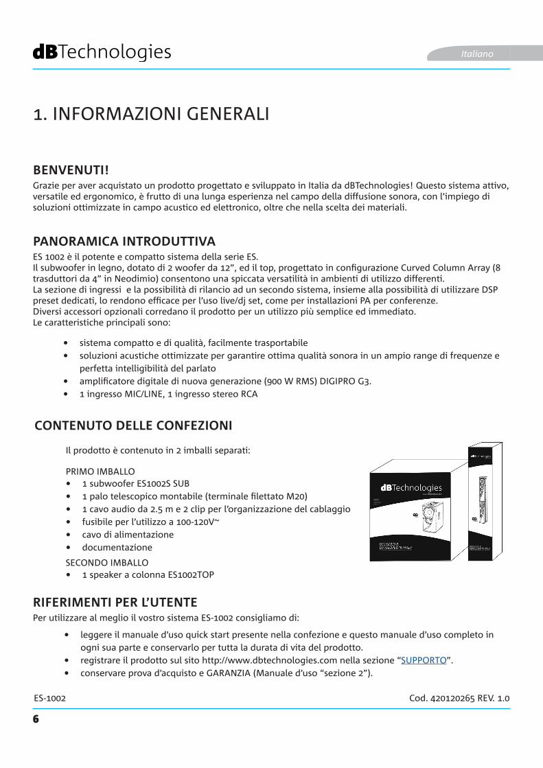
CONTENUTO DELLE CONFEZIONI
• 1 subwoofer ES1002S SUB• 1 palo telescopico montabile (terminale filettato M20)• 1 cavo audio da 2.5 m e 2 clip per l’organizzazione del cablaggio• fusibile per l’utilizzo a 100-120V~• cavo di alimentazione• documentazione
Il prodotto è contenuto in 2 imballi separati:
PRIMO IMBALLO
SECONDO IMBALLO• 1 speaker a colonna ES1002TOP
7
ES-1002 Cod. 420120265 REV. 1.0
CARATTERISTICHE MECCANICHE ED ACUSTICHE
DIMENSIONI
COPERTURA ACUSTICA
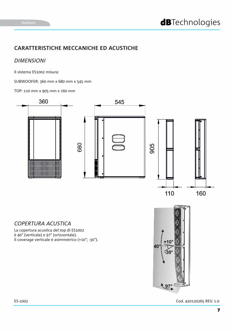
Il sistema ES1002 misura:
SUBWOOFER: 360 mm x 680 mm x 545 mm
TOP: 110 mm x 905 mm x 160 mm
La copertura acustica del top di ES1002è 40° (verticale) e 97° (orizzontale). Il coverage verticale è asimmetrico (+10°; -30°).
Italiano

8
ES-1002 Cod. 420120265 REV. 1.0
MONTAGGIO DEL PALO TELESCOPICO FORNITO SUL SUBWOOFER
Il subwoofer (ES1002 SUB) è dotato di 3 maniglie per il trasporto [Y]: 2 laterali ed una superiore. Nel lato superiore è presente anche un foro filettato M20 [Z] per l’inserimento del palo telescopico a corredo.Per montare il palo telescopico:• Avvitare con movimento destrorso la parte superiore (telescopica) su quella inferiore (fissa)• Avvitare con movimento destrorso il palo così ottenuto nel foro [Z]Il palo regolabile in altezza si inserisce nel foro [X] del top. Consultare il capitolo 2. CONFIGURAZIONI DI UTILIZZO per ulteriori informazioni e per le altezze massime ammesse nell’installazione.
Italiano
COMPLETAMENTO DEL SISTEMA
Il top (ES1002 TOP) è dotato sul lato inferiore di un foro diametro 36 mm [A] e di una connessione [B] per il cavo con connettore speak-on a corredo• Inserire il connettore speak-on come mostrato in figura• Inserire il top sul palo precedentemente avvitatoPer ulteriori informazioni sul cablaggio vedi il capitolo 3 PRIMA ACCENSIONE.

9
ES-1002 Cod. 420120265 REV. 1.0
CARATTERISTICHE DELLA SEZIONE DI AMPLIFICAZIONE E DI CONTROLLO
L’amplificatore digitale in classe D, è il cuore della serie ES. Il sistema è silenzioso ed il controllo è affidato a un potente DSP dedicato che gestisce diversi parametri. Questi sono completamente configurabili grazie all’interfaccia di controllo.La potenza di amplificazione sonora è di 900 W RMS.
Il pannello di ES1002 è caratterizzato da:
ATTENZIONE!
• Sezione di Input, Output e Controllo• Sezione di Alimentazione e Collegamento
deLtop
Italiano
• Non ostruire le alette posteriori di raffreddamento dell’amplificatore. In caso di surriscaldamento eccessivo, il volume audio viene ridotto gradualmente fino alla stabilizzazione termica del modulo. Il livello viene ristabilito automaticamente al raggiungimento della corretta temperatura di funzionamento.
• Non tentare in nessun modo di aprire l’amplificatore.
• In caso di malfunzionamento, interrompere immediatamente l’alimentazione, scollegando il modulo dalla rete, e contattare un riparatore autorizzato.
• Il sistema viene fornito con un fusibile già montato per operare nel range 220-240 V. Se è necessario operare nel range di tensione 100-120 V:
1. Disconnettere ogni connessione, compresa l’alimentazione.
2. Attendere 5 minuti.3. Sostituire il fusibile con quello fornito
nella confezione per il range 100-120 V.
• Utilizzare solo i cavi in dotazione.
• Non rimuovere mai la griglia frontale di protezione del prodotto. Per prevenire il pericolo di scossa elettrica, in caso di danneggiamento accidentale o sostituzione della griglia di protezione (da effettuarsi presso il servizio assistenza), disconnettere immediatamente l’alimentazione. Non connettere mai l’alimentazione di rete mentre la griglia è rimossa.
ATTENZIONE!
SEZI
ON
E D
I IN
PUT,
O
UTP
UT
E D
I CO
NTR
OLL
OA
MPL
IFIC
ATO
RE
SEZI
ON
E D
I A
LIM
ENTA
-ZI
ON
E E
CO
LLEG
AM
ENTO
D
EI T
OP
10
ES-1002 Cod. 420120265 REV. 1.0
SEZIONE DI INPUT, OUTPUT E DI CONTROLLO
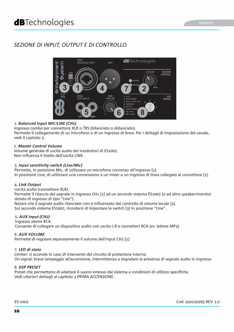
1. Balanced Input MIC/LINE (CH1)Ingresso combo per connettore XLR o TRS (bilanciato o sbilanciato). Permette il collegamento di un microfono o di un ingresso di linea. Per i dettagli di impostazione del canale, vedi il capitolo 3.
Italiano
2. Master Control VolumeVolume generale di uscita audio dei trasduttori di ES1002.Non influenza il livello dell’uscita LINK.
5. AUX Input (CH2) Ingresso stereo RCA.Consente di collegare un dispositivo audio con uscita L-R e connettori RCA (es. lettore MP3).
3. Input sensitivity switch (Line/Mic)Permette, in posizione Mic, di utilizzare un microfono connesso all’ingresso [1].In posizione Line, di utilizzare una connessione a un mixer o un ingresso di linea collegato al connettore [1].
4. Link OutputUscita audio (connettore XLR).Permette il rilancio del segnale in ingresso CH1 [1] ad un secondo sistema ES1002 (o ad altro speaker/monitor dotato di ingresso di tipo “Line”). Notare che il segnale audio rilanciato non è influenzato dal controllo di volume locale [2].Sul secondo sistema ES1002, ricordarsi di impostare lo switch [3] in posizione “Line”.
6. AUX VOLUMEPermette di regolare separatamente il volume dell’input CH2 [5]
7. LED di statoLimiter: si accende in caso di intervento del circuito di protezione interna.On-signal: breve lampeggio all’accensione, intermittenza a segnalare la presenza di segnale audio in ingresso
8. DSP PRESET Preset che permettono di adattare il suono emesso dal sistema a condizioni di utilizzo specifiche.Vedi ulteriori dettagli al capitolo 3 PRIMA ACCENSIONE.
11
ES-1002 Cod. 420120265 REV. 1.0
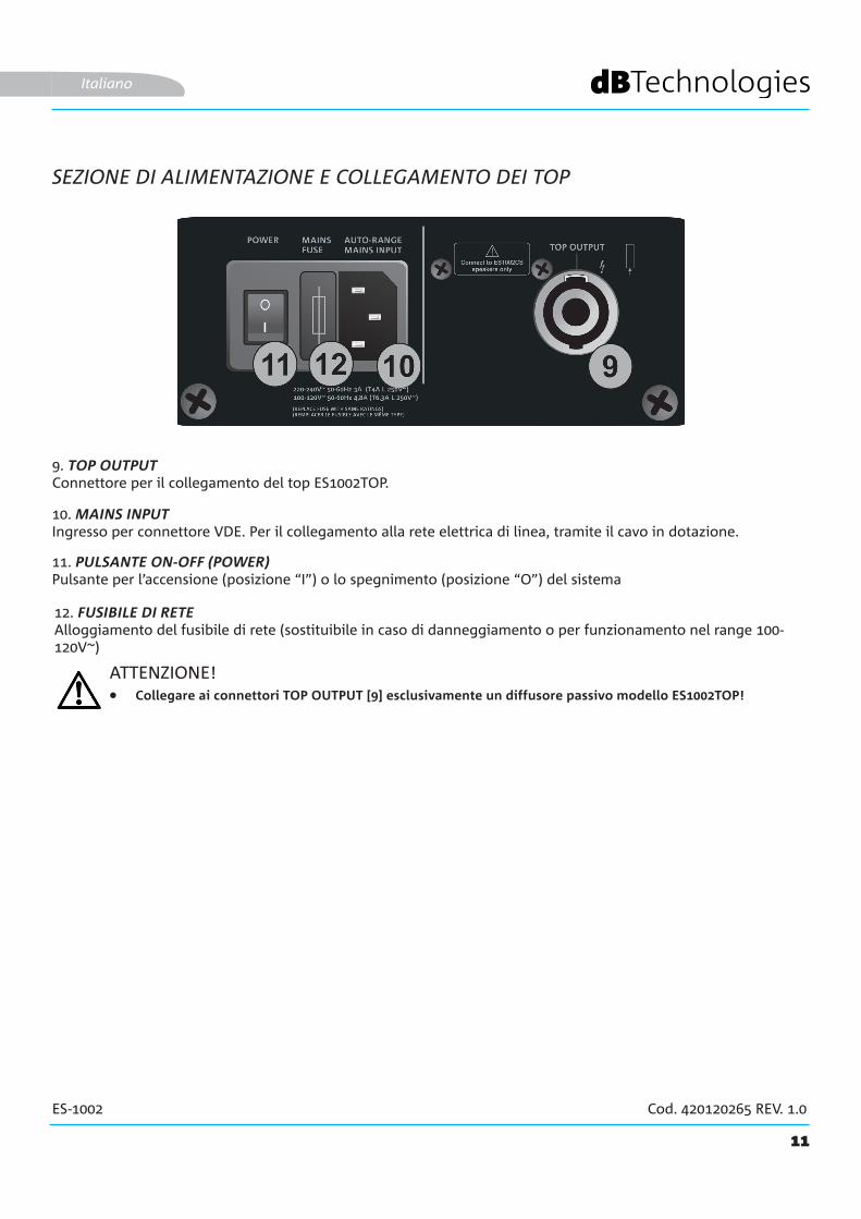
10. MAINS INPUTIngresso per connettore VDE. Per il collegamento alla rete elettrica di linea, tramite il cavo in dotazione.
9. TOP OUTPUTConnettore per il collegamento del top ES1002TOP.
SEZIONE DI ALIMENTAZIONE E COLLEGAMENTO DEI TOP
Italiano
11. PULSANTE ON-OFF (POWER)Pulsante per l’accensione (posizione “I”) o lo spegnimento (posizione “O”) del sistema
12. FUSIBILE DI RETEAlloggiamento del fusibile di rete (sostituibile in caso di danneggiamento o per funzionamento nel range 100-120V~)
ATTENZIONE!• Collegare ai connettori TOP OUTPUT [9] esclusivamente un diffusore passivo modello ES1002TOP!
12
ES-1002 Cod. 420120265 REV. 1.0
2. CONFIGURAZIONI DI UTILIZZO
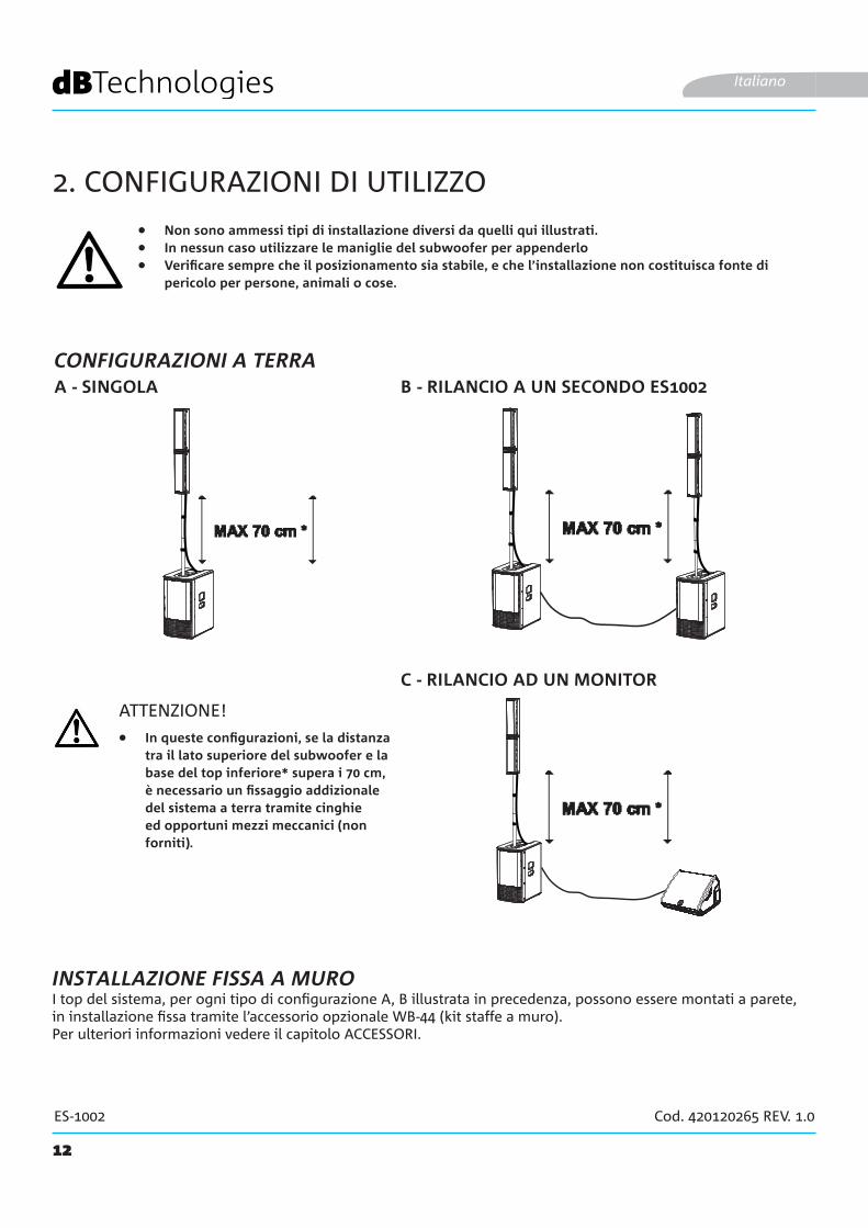
• Non sono ammessi tipi di installazione diversi da quelli qui illustrati.• In nessun caso utilizzare le maniglie del subwoofer per appenderlo• Verificare sempre che il posizionamento sia stabile, e che l’installazione non costituisca fonte di
pericolo per persone, animali o cose.
B - RILANCIO A UN SECONDO ES1002A - SINGOLA
Italiano
ATTENZIONE!
I top del sistema, per ogni tipo di configurazione A, B illustrata in precedenza, possono essere montati a parete, in installazione fissa tramite l’accessorio opzionale WB-44 (kit staffe a muro).Per ulteriori informazioni vedere il capitolo ACCESSORI.
INSTALLAZIONE FISSA A MURO
• In queste configurazioni, se la distanza tra il lato superiore del subwoofer e la base del top inferiore* supera i 70 cm, è necessario un fissaggio addizionale del sistema a terra tramite cinghie ed opportuni mezzi meccanici (non forniti).
C - RILANCIO AD UN MONITOR
CONFIGURAZIONI A TERRA

13
ES-1002 Cod. 420120265 REV. 1.0
3. PRIMA ACCENSIONE
COLLEGAMENTO DEL TOP AL SUBWOOFER
Italiano
Dopo aver montato il top su palo come da paragrafo relativo, è necessario il collegamento al subwoofer:
• Assicurarsi che il top sul palo telescopico montato in precedenza sul subwoofer sia inserito
• Utilizzare il cavo da 2.5 m in dotazione.• Collegare il top nel connettore inferiore come mostrato• Effettuare il collegamento del sub
nel connettore TOP OUTPUT[9] • Utilizzare le clip in dotazione per fissare
il cavo intorno al palo telescopico
RL
RL
STEREO INPUT
14
ES-1002 Cod. 420120265 REV. 1.0
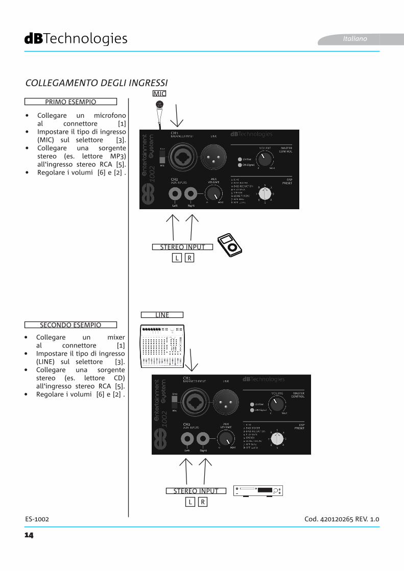
COLLEGAMENTO DEGLI INGRESSI
Italiano
• Collegare un microfono al connettore [1]
• Impostare il tipo di ingresso (MIC) sul selettore [3].
• Collegare una sorgente stereo (es. lettore MP3) all’ingresso stereo RCA [5].
• Regolare i volumi [6] e [2] .
MIC
STEREO INPUT
PRIMO ESEMPIO
LINE
SECONDO ESEMPIO
• Collegare un mixer al connettore [1]
• Impostare il tipo di ingresso (LINE) sul selettore [3].
• Collegare una sorgente stereo (es. lettore CD) all’ingresso stereo RCA [5].
• Regolare i volumi [6] e [2] .
15
ES-1002 Cod. 420120265 REV. 1.0
MONITORES 1002
Italiano
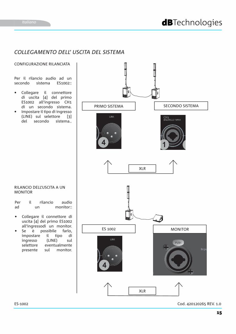
COLLEGAMENTO DELL’ USCITA DEL SISTEMA
Per il rilancio audio ad un secondo sistema ES1002::
• Collegare il connettore di uscita [4] del primo ES1002 all’ingresso CH1 di un secondo sistema.
• Impostare il tipo di ingresso (LINE) sul selettore [3] del secondo sistema..
PRIMO SISTEMA SECONDO SISTEMA
CONFIGURAZIONE RILANCIATA
RILANCIO DELL’USCITA A UN MONITOR
XLR
XLR
Per il rilancio audio ad un monitor::
• Collegare il connettore di uscita [4] del primo ES1002 all’ingressodi un monitor.
• Se è possibile farlo, impostare il tipo di ingresso (LINE) sul selettore eventualmente presente sul monitor.
16
ES-1002 Cod. 420120265 REV. 1.0
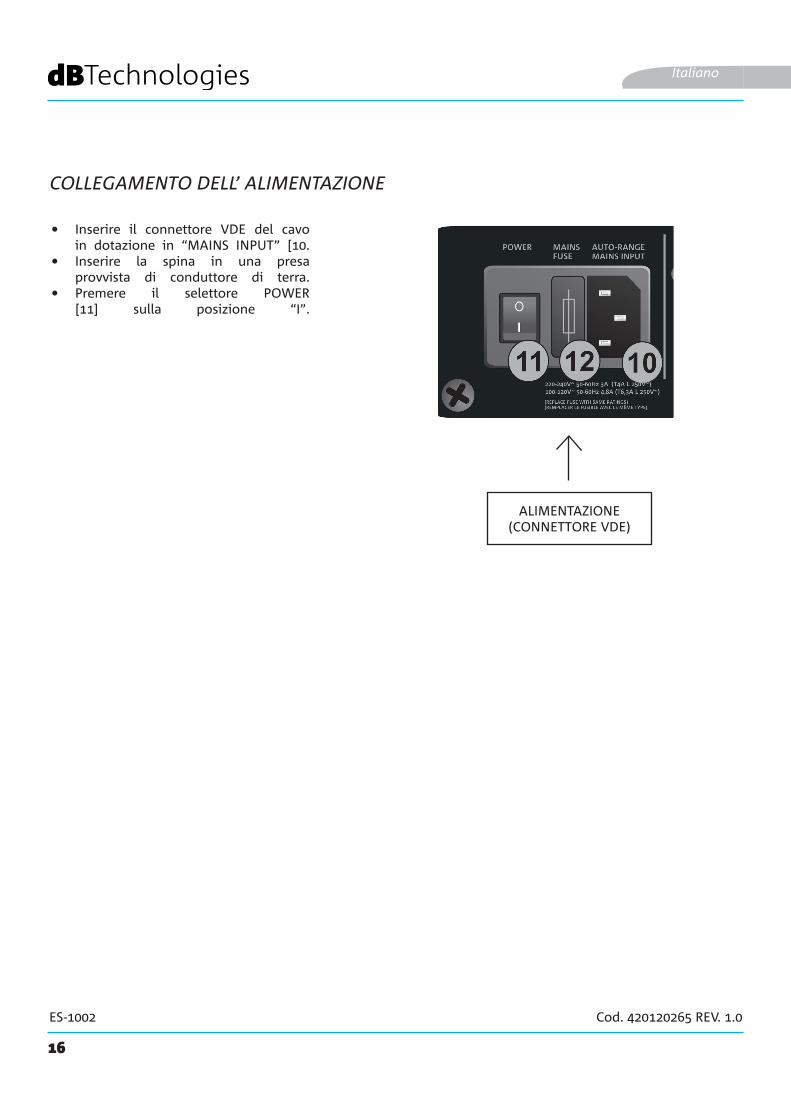
COLLEGAMENTO DELL’ ALIMENTAZIONE
Italiano
ALIMENTAZIONE(CONNETTORE VDE)
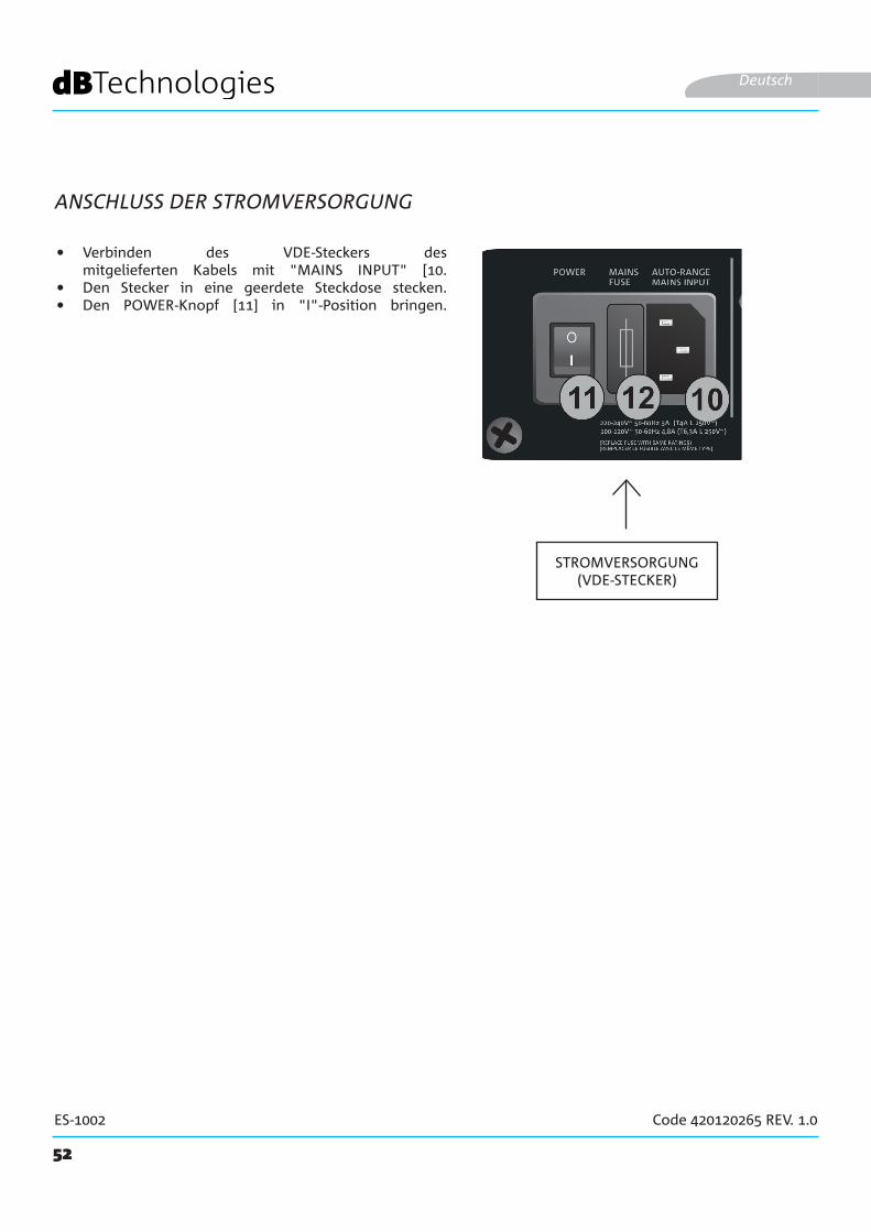
• Inserire il connettore VDE del cavo in dotazione in “MAINS INPUT” [10.
• Inserire la spina in una presa provvista di conduttore di terra.
• Premere il selettore POWER [11] sulla posizione “I”.
DP-ES1203DO-ES212
17
ES-1002 Cod. 420120265 REV. 1.0
WB-44
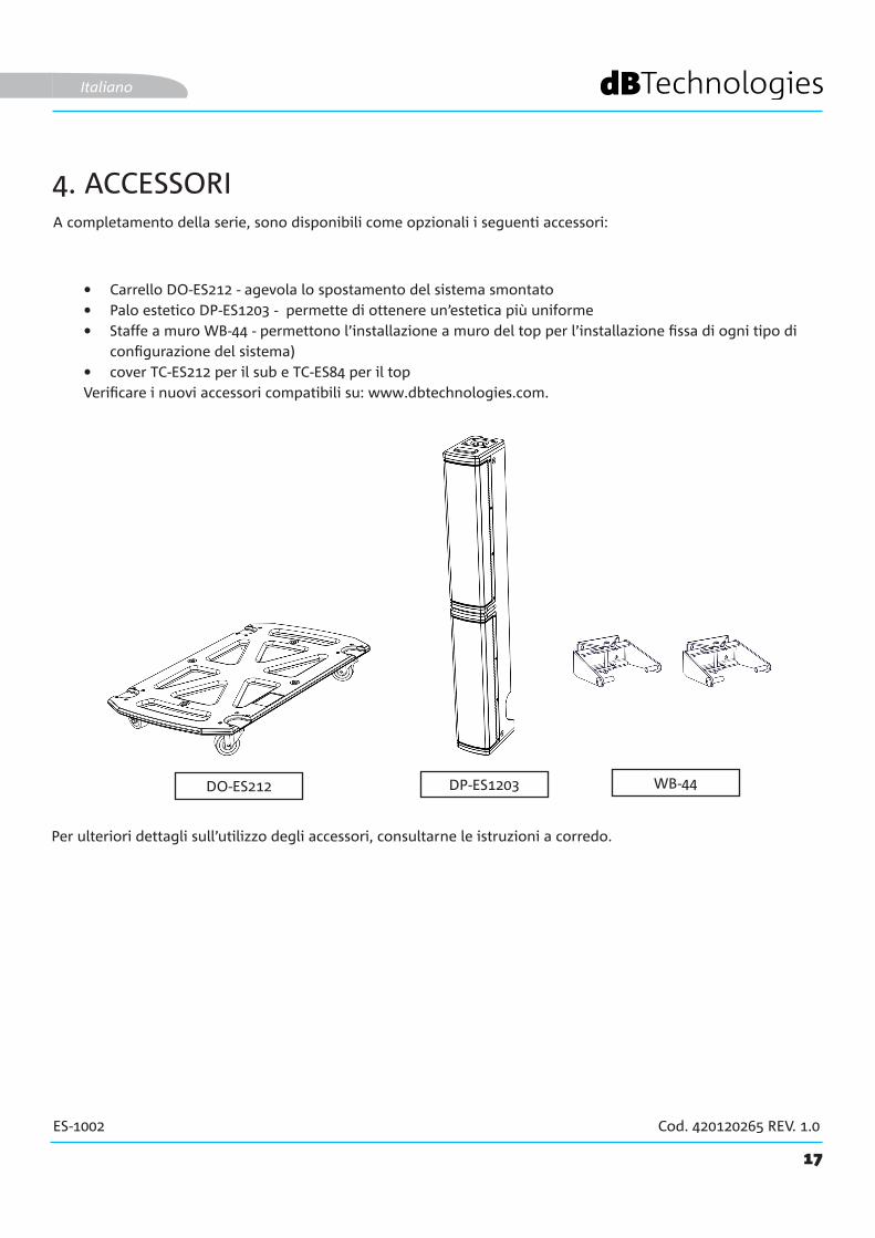
A completamento della serie, sono disponibili come opzionali i seguenti accessori:
• Carrello DO-ES212 - agevola lo spostamento del sistema smontato• Palo estetico DP-ES1203 - permette di ottenere un’estetica più uniforme • Staffe a muro WB-44 - permettono l’installazione a muro del top per l’installazione fissa di ogni tipo di
configurazione del sistema)• cover TC-ES212 per il sub e TC-ES84 per il topVerificare i nuovi accessori compatibili su: www.dbtechnologies.com.
Italiano
4. ACCESSORI
Per ulteriori dettagli sull’utilizzo degli accessori, consultarne le istruzioni a corredo.
18
ES-1002 Cod. 420120265 REV. 1.0
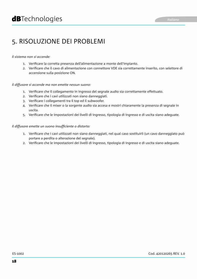
5. RISOLUZIONE DEI PROBLEMI
1. Verificare la corretta presenza dell’alimentazione a monte dell’impianto.2. Verificare che il cavo di alimentazione con connettore VDE sia correttamente inserito, con selettore di
accensione sulla posizione ON.
1. Verificare che il collegamento in ingresso del segnale audio sia correttamente effettuato.2. Verificare che i cavi utilizzati non siano danneggiati.3. Verificare i collegamenti tra il top ed il subwoofer.4. Verificare che il mixer o la sorgente audio sia accesa e mostri chiaramente la presenza di segnale in
uscita.5. Verificare che le impostazioni dei livelli di ingresso, tipologia di ingresso e di uscita siano adeguate.
1. Verificare che i cavi utilizzati non siano danneggiati, nel qual caso sostituirli (un cavo danneggiato può portare a perdita o alterazione del segnale).
2. Verificare che le impostazioni dei livelli di ingresso, tipologia di ingresso e di uscita siano adeguate.
Il sistema non si accende:
Il diffusore si accende ma non emette nessun suono:
Il diffusore emette un suono insufficiente o distorto:
Italiano
19
ES-1002 Cod. 420120265 REV. 1.0
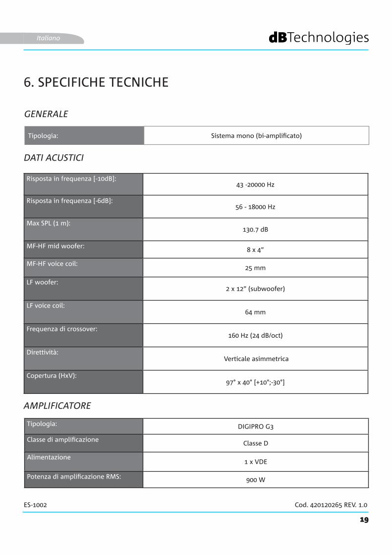
6. SPECIFICHE TECNICHE
GENERALE
DATI ACUSTICI
AMPLIFICATORE
Tipologia: Sistema mono (bi-amplificato)
Italiano
Risposta in frequenza [-10dB]: 43 -20000 Hz
Risposta in frequenza [-6dB]: 56 - 18000 Hz
Max SPL (1 m):130.7 dB
MF-HF mid woofer: 8 x 4”
MF-HF voice coil:25 mm
LF woofer:2 x 12” (subwoofer)
LF voice coil:64 mm
Frequenza di crossover:160 Hz (24 dB/oct)
Direttività: Verticale asimmetrica
Copertura (HxV):97° x 40° [+10°;-30°]
Tipologia: DIGIPRO G3
Classe di amplificazione Classe D
Alimentazione1 x VDE
Potenza di amplificazione RMS: 900 W
20
ES-1002 Cod. 420120265 REV. 1.0
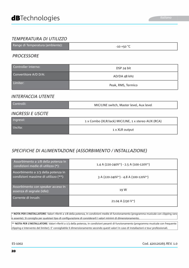
PROCESSORE
INGRESSI E USCITE
Italiano
INTERFACCIA UTENTE
Assorbimento a 1/8 della potenza in condizioni medie di utilizzo (*): 1.4 A (220-240V~) - 2.5 A (100-120V~)
Assorbimento a 1/3 della potenza in condizioni massime di utilizzo (**): 3 A (220-240V~) - 4.8 A (100-120V~)
Assorbimento con speaker acceso in assenza di segnale (idle): 19 W
Corrente di inrush:21.04 A (230 V~)
SPECIFICHE DI ALIMENTAZIONE (ASSORBIMENTO / INSTALLAZIONE)
* NOTA PER L’INSTALLATORE: Valori riferiti a 1/8 della potenza, in condizioni medie di funzionamento (programma musicale con clipping raro
o assente). Si consiglia per qualsiasi tipo di configurazione di considerarli i valori minimi di dimensionamento.
** NOTA PER L’INSTALLATORE: Valori riferiti a 1/3 della potenza, in condizioni pesanti di funzionamento (programma musicale con frequente
clipping e intervento del limiter). E’ consigliabile il dimensionamento secondo questi valori in caso di installazioni e tour professionali.
Controller interno: DSP 24 bit
Convertitore A/D D/A: AD/DA 48 kHz
Limiter:Peak, RMS, Termico
Controlli: MIC/LINE switch, Master level, Aux level
Ingressi: 1 x Combo (XLR/Jack) MIC/LINE, 1 x stereo AUX (RCA)
Uscita:1 x XLR output
TEMPERATURA DI UTILIZZORange di Temperatura (ambiente): -10 +50 °C

21
ES-1002 Cod. 420120265 REV. 1.0
DIMENSIONI
Caratteristiche, specifiche e aspetto dei prodotti sono soggetti a possibili cambiamenti senza previa comunicazione. dBTechnologies si riserva il diritto di apportare cambiamenti o miglioramenti nel design o nelle lavorazioni senza assumersi l’obbligo di cambiare o migliorare anche i prodotti precedentemente realizzati.
A.E.B. Industriale SrlVia Brodolini, 8
Località Crespellano40053 VALSAMOGGIA
BOLOGNA (ITALIA)
Tel +39 051 969870Fax +39 051 969725
Italiano
Materiale: Legno (multistrato)
Griglia: Metallo, spessore 1,5 mm, lavorazione CNC
Maniglie:3 (2 laterali, 1 superiore)
Montaggio su palo:Sì, con foro filettato M20
Larghezza: 360 mm (subwoofer) / 110 mm (top)
Altezza: 680 mm (subwoofer) / 905 mm (top)
Profondità: 545 mm (subwoofer) / 160 mm (top)
Peso: 29.3 kg (subwoofer) / 5.8 kg (top)

22
ES-1002 Cod. 420120265 REV. 1.0
CONTENTS
1. GENERAL INFORMATION .................................................................................................... 24WELCOME! ....................................................................................................................... 24INTRODUCTORY OVERVIEW ............................................................................................ 24PACKAGE CONTENTS ........................................................................................................ 24USER INFORMATION ........................................................................................................ 24MECHANICAL AND ACOUSTIC FEATURES ....................................................................... 25
DIMENSIONS ............................................................................................................................................ 25ACOUSTIC COVERAGE ............................................................................................................................. 25ASSEMBLING THE SUPPLIED TELESCOPIC POLE ON THE SUBWOOFER ............................................... 26COMPLETING THE SYSTEM ...................................................................................................................... 26
AMPLIFIER AND CONTROL SECTION FEATURES ............................................................. 27INPUT, OUTPUT AND CONTROL SECTION .............................................................................................. 27AMPLIFIER ................................................................................................................................................ 27POWER SUPPLY AND TOP CONNECTION SECTION ................................................................................ 27INPUT, OUTPUT AND CONTROL SECTION .............................................................................................. 28POWER SUPPLY AND TOP CONNECTION SECTION ................................................................................ 29
2. USAGE CONFIGURATIONS ................................................................................................ 30GROUND CONFIGURATIONS ........................................................................................ 30WALL MOUNTING .......................................................................................................... 30
3. FIRST SWITCH-ON ................................................................................................................ 31CONNECTING THE TOP TO THE SUBWOOFER ....................................................................................... 31CONNECTING THE INPUTS ...................................................................................................................... 32CONNECTING THE SYSTEM OUTPUT ...................................................................................................... 33CONNECTING POWER ............................................................................................................................. 34
4. ACCESSORIES ........................................................................................................................ 355. TROUBLESHOOTING ............................................................................................................ 366. TECHNICAL SPECIFICATIONS .............................................................................................. 37
GENERAL .................................................................................................................................................. 37ACOUSTIC DATA ....................................................................................................................................... 37AMPLIFIER ................................................................................................................................................ 37OPERATING TEMPERATURE..................................................................................................................... 38PROCESSOR .............................................................................................................................................. 38USER INTERFACE ...................................................................................................................................... 38INPUTS AND OUTPUTS ............................................................................................................................ 38POWER SUPPLY SPECIFICATIONS (CONSUMPTION / INSTALLATION) ................................................... 38DIMENSIONS ............................................................................................................................................ 39
23
ES-1002 Cod. 420120265 REV. 1.0
CONTENTS
English

24
ES-1002 Cod. 420120265 REV. 1.0
1. GENERAL INFORMATION
WELCOME!
INTRODUCTORY OVERVIEW
USER INFORMATION
Thanks for purchasing a product that was designed and developed in Italy by dBTechnologies! This active, versatile and ergonomic system is the result of long experience in the field of sound diffusion. It uses optimised acoustic and electronic solutions as well as an optimal choice of materials.
The ES 1002 is a powerful and compact system in the ES range.Its wooden subwoofer, equipped with two 12" woofers, and its top, designed with a Curved Column Array configuration (eight 4" neodymium transducers) make it very versatile in various different usage environments.Its input section and ability to repeat the signal to a second system, together with its dedicated DSP presets, make it as effective when used for live/dj sets as when used as a PA for conferences.There are various optional accessories to complete the product for easy and immediate use. Its main features are:
To use your ES-1002 system in the best way, we recommend that you:
• compact high-quality system that is easy to transport• optimised acoustic solutions to ensure excellent sound quality over a wide frequency range and
perfect speech intelligibility • new generation DIGIPRO G3 digital amplifier (900 W RMS).• 1 MIC/LINE input, 1 stereo RCA input
• read the quick start user manual in the package and all of this full user manual, and keep it for the whole life of the product.
• register the product in the “SUPPORT” section at http://www.dbtechnologies.com/en/home.• keep proof of purchase and the WARRANTY (User manual “section 2”).
English
PACKAGE CONTENTS
• 1 ES1002S SUB subwoofer• 1 mountable telescopic pole (M20 threaded end)• 1 2.5 m audio cable and 2 clips to organise the cabling• fuse for operation at 100-120 V~• power cable• documentation
The product is comes in two separate packages:
FIRST PACKAGE
SECOND PACKAGE• 1 ES1002TOP column speaker

25
ES-1002 Cod. 420120265 REV. 1.0
MECHANICAL AND ACOUSTIC FEATURES
DIMENSIONS
ACOUSTIC COVERAGE
The measurements of the ES1002 system are:
SUBWOOFER: 360 mm x 680 mm x 545 mm
TOP: 110 mm x 905 mm x 160 mm
The acoustic coverage of the ES1002 topis 40° (vertical) and 97° (horizontal). Its vertical coverage is asymmetrical (+10°; -30°).
English

26
ES-1002 Cod. 420120265 REV. 1.0
ASSEMBLING THE SUPPLIED TELESCOPIC POLE ON THE SUBWOOFER
The subwoofer (ES1002 SUB) has three transport handles [Y]: Two on the sides and one at the top. There is also an M20 threaded hole [Z] in the top for inserting the telescopic pole provided.To assemble the telescopic pole:• Screw the top (telescopic) part onto the lower (fixed) part with a clockwise movement• Screw the resulting pole into the hole [Z] with a clockwise movementInsert the adjustable pole into the hole [X] in the top. Refer to chapter 2, USAGE CONFIGURATIONS, for further information and the maximum allowed installation heights.
English
COMPLETING THE SYSTEM
At the front of the top (ES1002 TOP), there is a 36 mm diameter hole [A] and a connector [B] for the supplied cable with speak-on connector• Insert the speak-on connector as shown in the figure• Insert the top onto the pole previously screwed into placeSee chapter 3, FIRST SWITCH-ON, for further information on the cabling.
27
ES-1002 Cod. 420120265 REV. 1.0
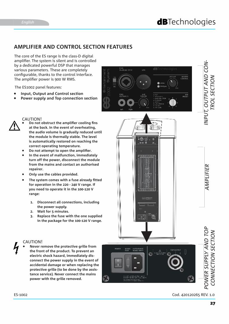
AMPLIFIER AND CONTROL SECTION FEATURES
The core of the ES range is the class-D digital amplifier. The system is silent and is controlled by a dedicated powerful DSP that manages various parameters. These are completely configurable, thanks to the control interface.The amplifier power is 900 W RMS.
The ES1002 panel features:
CAUTION!
• Input, Output and Control section• Power supply and Top connection section
English
• Do not obstruct the amplifier cooling fins at the back. In the event of overheating, the audio volume is gradually reduced until the module is thermally stable. The level is automatically restored on reaching the correct operating temperature.
• Do not attempt to open the amplifier.• In the event of malfunction, immediately
turn off the power, disconnect the module from the mains and contact an authorised repairer.
• The system comes with a fuse already fitted for operation in the 220 - 240 V range. If you need to operate it in the 100-120 V range:
1. Disconnect all connections, including the power supply.
2. Wait for 5 minutes.3. Replace the fuse with the one supplied
in the package for the 100-120 V range.
• Only use the cables provided.
• Never remove the protective grille from the front of the product. To prevent an electric shock hazard, immediately dis-connect the power supply in the event of accidental damage or when replacing the protective grille (to be done by the assis-tance service). Never connect the mains power with the grille removed.
CAUTION!
INPU
T, O
UTP
UT
AN
D C
ON
-TR
OL
SEC
TIO
NA
MPL
IFIE
RPO
WER
SU
PPLY
AN
D T
OP
CO
NN
ECTI
ON
SEC
TIO
N
28
ES-1002 Cod. 420120265 REV. 1.0
INPUT, OUTPUT AND CONTROL SECTION
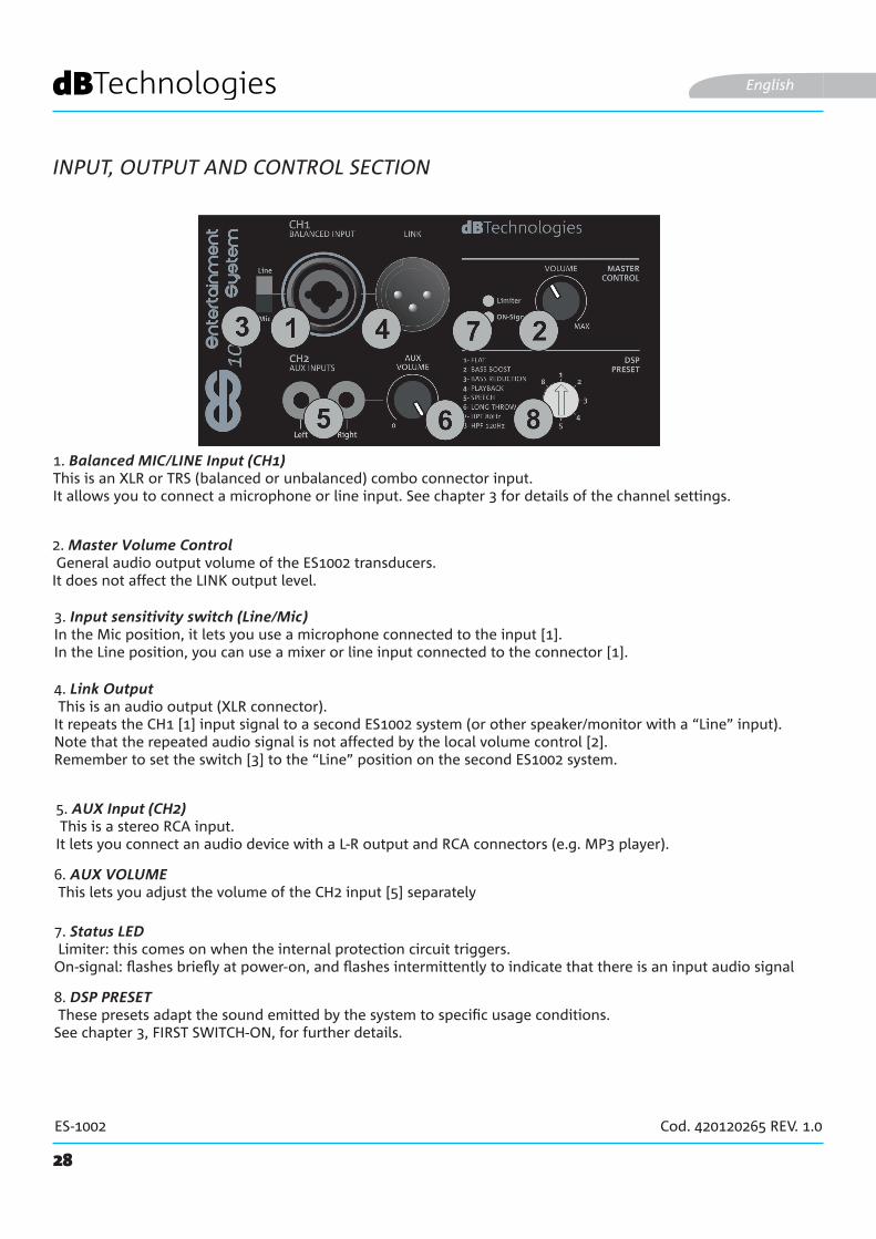
1. Balanced MIC/LINE Input (CH1) This is an XLR or TRS (balanced or unbalanced) combo connector input. It allows you to connect a microphone or line input. See chapter 3 for details of the channel settings.
English
2. Master Volume Control General audio output volume of the ES1002 transducers.It does not affect the LINK output level.
5. AUX Input (CH2) This is a stereo RCA input.It lets you connect an audio device with a L-R output and RCA connectors (e.g. MP3 player).
3. Input sensitivity switch (Line/Mic) In the Mic position, it lets you use a microphone connected to the input [1].In the Line position, you can use a mixer or line input connected to the connector [1].
4. Link Output This is an audio output (XLR connector).It repeats the CH1 [1] input signal to a second ES1002 system (or other speaker/monitor with a “Line” input). Note that the repeated audio signal is not affected by the local volume control [2].Remember to set the switch [3] to the “Line” position on the second ES1002 system.
6. AUX VOLUME This lets you adjust the volume of the CH2 input [5] separately
7. Status LED Limiter: this comes on when the internal protection circuit triggers.On-signal: flashes briefly at power-on, and flashes intermittently to indicate that there is an input audio signal
8. DSP PRESET These presets adapt the sound emitted by the system to specific usage conditions.See chapter 3, FIRST SWITCH-ON, for further details.

29
ES-1002 Cod. 420120265 REV. 1.0
10. MAINS INPUT This is a VDE connector input. It is for connecting the power line, using the cable provided.
9. TOP OUTPUT This connector is for connecting the ES1002TOP top.
POWER SUPPLY AND TOP CONNECTION SECTION
English
11. ON-OFF (POWER) BUTTON This switch turns the system on (“I” position) or off (“O”position)
12. MAINS FUSE This is the mains fuse holder (replaceable when blown or for operation in the 100-120 V~ range)
CAUTION!• Connect only an ES1002TOP passive diffuser to the TOP OUTPUT connectors [9]!
30
ES-1002 Cod. 420120265 REV. 1.0
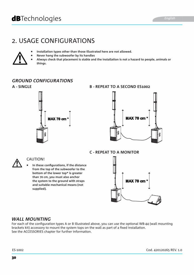
2. USAGE CONFIGURATIONS
• Installation types other than those illustrated here are not allowed.• Never hang the subwoofer by its handles• Always check that placement is stable and the installation is not a hazard to people, animals or
things.
B - REPEAT TO A SECOND ES1002A - SINGLE
English
CAUTION!
For each of the configuration types A or B illustrated above, you can use the optional WB-44 (wall mounting brackets kit) accessory to mount the system tops on the wall as part of a fixed installation.See the ACCESSORIES chapter for further information.
WALL MOUNTING
• In these configurations, if the distance from the top of the subwoofer to the bottom of the lower top* is greater than 70 cm, you must also anchor the system to the ground with straps and suitable mechanical means (not supplied).
C - REPEAT TO A MONITOR
GROUND CONFIGURATIONS
31
ES-1002 Cod. 420120265 REV. 1.0
3. FIRST SWITCH-ON
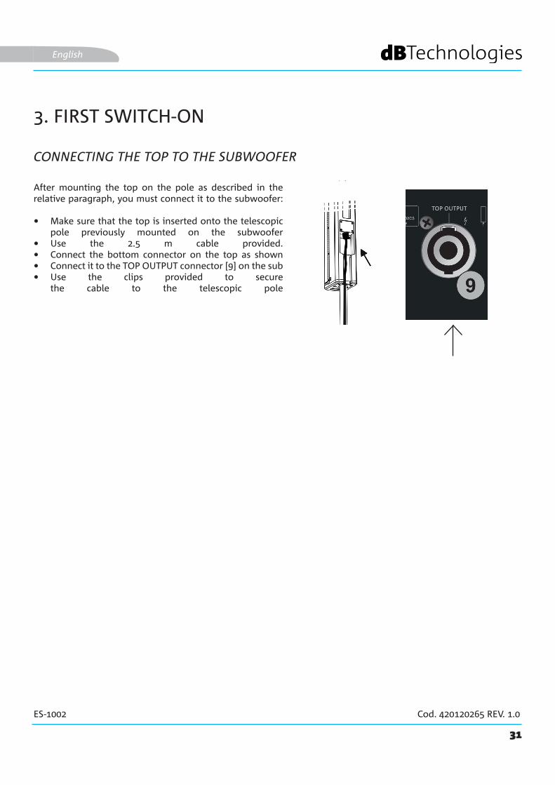
CONNECTING THE TOP TO THE SUBWOOFER
English
After mounting the top on the pole as described in the relative paragraph, you must connect it to the subwoofer:
• Make sure that the top is inserted onto the telescopic pole previously mounted on the subwoofer
• Use the 2.5 m cable provided.• Connect the bottom connector on the top as shown• Connect it to the TOP OUTPUT connector [9] on the sub • Use the clips provided to secure
the cable to the telescopic pole

RL
RL
STEREO INPUT
32
ES-1002 Cod. 420120265 REV. 1.0
CONNECTING THE INPUTS
English
• Connect a microphone to connector [1]
• Set the input type (MIC) on the selector switch [3].
• Connect a stereo source (e.g. MP3 player) to the stereo RCA input [5].
• Adjust the volumes [6] and [2].
MIC
STEREO INPUT
FIRST EXAMPLE
LINE
SECOND EXAMPLE
• Connect a mixer to connector [1]
• Set the input type (LINE) on the selector switch [3].
• Connect a stereo source (e.g. CD player) to the stereo RCA input [5].
• Adjust the volumes [6] and [2].
33
ES-1002 Cod. 420120265 REV. 1.0
MONITORES 1002
English
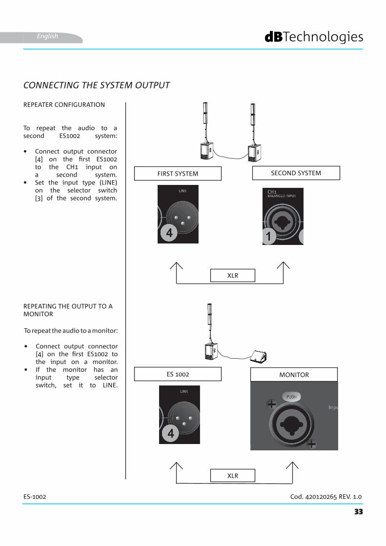
CONNECTING THE SYSTEM OUTPUT
To repeat the audio to a second ES1002 system:
• Connect output connector [4] on the first ES1002 to the CH1 input on a second system.
• Set the input type (LINE) on the selector switch [3] of the second system.
FIRST SYSTEM SECOND SYSTEM
REPEATER CONFIGURATION
REPEATING THE OUTPUT TO A MONITOR
XLR
XLR
To repeat the audio to a monitor:
• Connect output connector [4] on the first ES1002 to the input on a monitor.
• If the monitor has an input type selector switch, set it to LINE.
34
ES-1002 Cod. 420120265 REV. 1.0
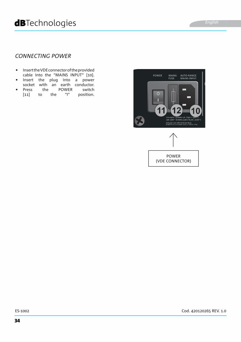
CONNECTING POWER
English
POWER(VDE CONNECTOR)
• Insert the VDE connector of the provided cable into the “MAINS INPUT” [10].
• Insert the plug into a power socket with an earth conductor.
• Press the POWER switch [11] to the “I” position.
DP-ES1203DO-ES212
35
ES-1002 Cod. 420120265 REV. 1.0
WB-44
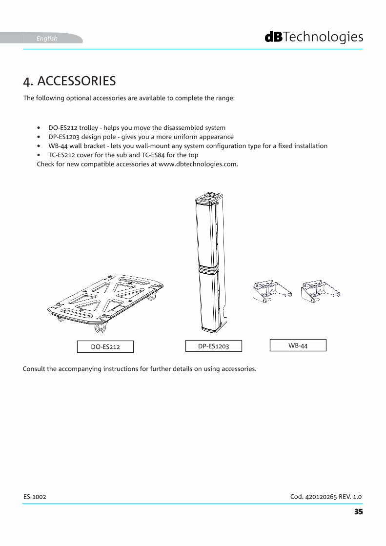
The following optional accessories are available to complete the range:
• DO-ES212 trolley - helps you move the disassembled system• DP-ES1203 design pole - gives you a more uniform appearance • WB-44 wall bracket - lets you wall-mount any system configuration type for a fixed installation• TC-ES212 cover for the sub and TC-ES84 for the topCheck for new compatible accessories at www.dbtechnologies.com.
English
4. ACCESSORIES
Consult the accompanying instructions for further details on using accessories.
36
ES-1002 Cod. 420120265 REV. 1.0
5. TROUBLESHOOTING
1. Check that the system is connected to a working power supply.2. Check that the power cable with VDE connector is plugged in properly and that the power switch is in
the ON position.
1. Check that the audio signal input is connected correctly.2. Check that the cables used are not damaged.3. Check the connections between the top and the subwoofer.4. Check that the mixer or audio source is on and clearly shows an output signal.5. Check that the input level, input type and output level are suitable.
1. Check that the cables used are not damaged. If they are, replace them ( a damaged cable may cause signal loss or alteration).
2. Check that the input level, input type and output level are suitable.
The system will not turn on:
The diffuser turns on but does not emit any sound:
The sound emitted by the diffuser is insufficient or distorted:
English
37
ES-1002 Cod. 420120265 REV. 1.0
6. TECHNICAL SPECIFICATIONS
GENERAL
ACOUSTIC DATA
AMPLIFIER
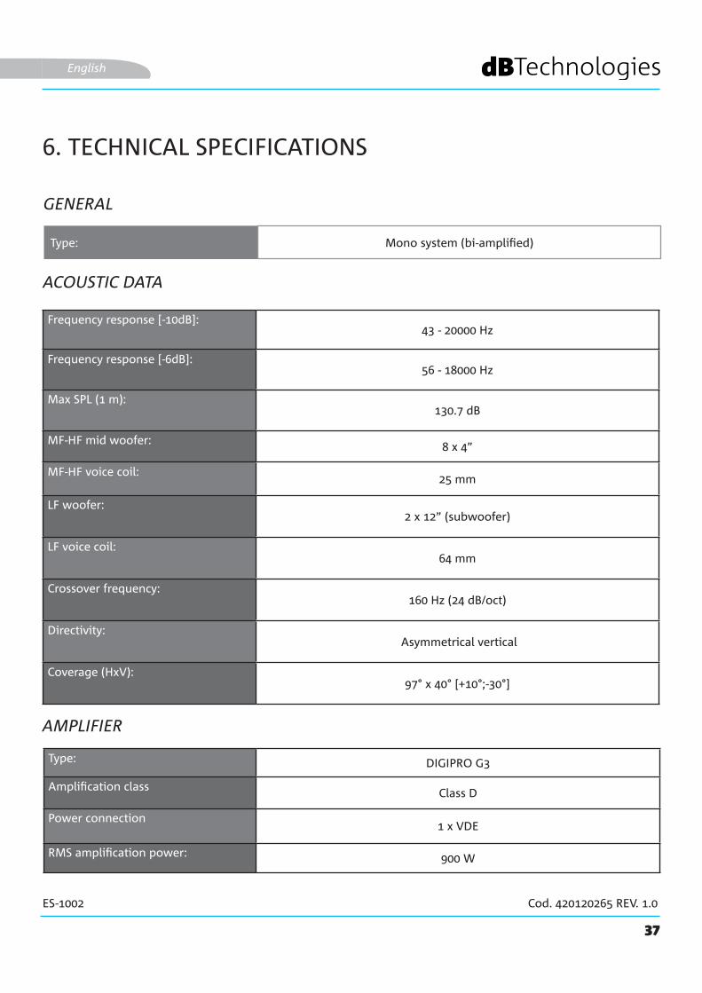
Type: Mono system (bi-amplified)
English
Frequency response [-10dB]: 43 - 20000 Hz
Frequency response [-6dB]: 56 - 18000 Hz
Max SPL (1 m):130.7 dB
MF-HF mid woofer: 8 x 4”
MF-HF voice coil:25 mm
LF woofer:2 x 12” (subwoofer)
LF voice coil:64 mm
Crossover frequency:160 Hz (24 dB/oct)
Directivity: Asymmetrical vertical
Coverage (HxV):97° x 40° [+10°;-30°]
Type: DIGIPRO G3
Amplification class Class D
Power connection1 x VDE
RMS amplification power: 900 W
38
ES-1002 Cod. 420120265 REV. 1.0
PROCESSOR
INPUTS AND OUTPUTS
English
USER INTERFACE
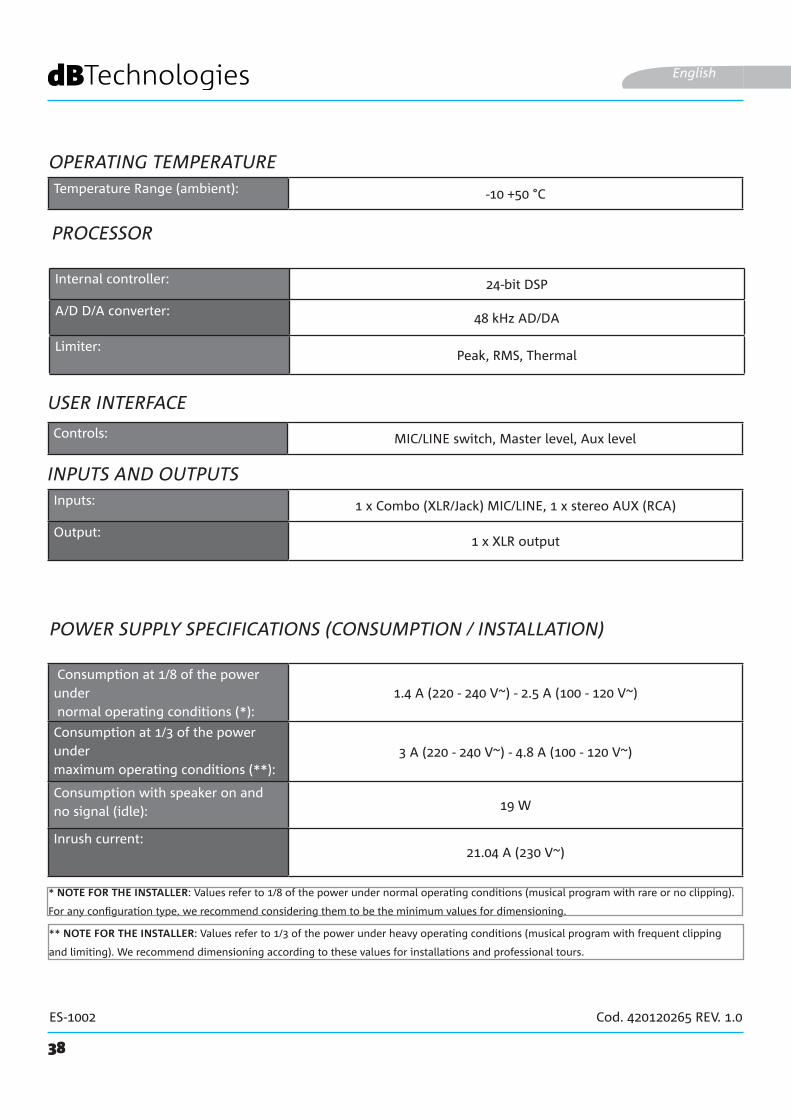
Consumption at 1/8 of the power under normal operating conditions (*):
1.4 A (220 - 240 V~) - 2.5 A (100 - 120 V~)
Consumption at 1/3 of the power under maximum operating conditions (**):
3 A (220 - 240 V~) - 4.8 A (100 - 120 V~)
Consumption with speaker on and no signal (idle): 19 W
Inrush current:21.04 A (230 V~)
POWER SUPPLY SPECIFICATIONS (CONSUMPTION / INSTALLATION)
* NOTE FOR THE INSTALLER: Values refer to 1/8 of the power under normal operating conditions (musical program with rare or no clipping).
For any configuration type, we recommend considering them to be the minimum values for dimensioning.
** NOTE FOR THE INSTALLER: Values refer to 1/3 of the power under heavy operating conditions (musical program with frequent clipping
and limiting). We recommend dimensioning according to these values for installations and professional tours.
Internal controller: 24-bit DSP
A/D D/A converter: 48 kHz AD/DA
Limiter:Peak, RMS, Thermal
Controls: MIC/LINE switch, Master level, Aux level
Inputs: 1 x Combo (XLR/Jack) MIC/LINE, 1 x stereo AUX (RCA)
Output:1 x XLR output
OPERATING TEMPERATURETemperature Range (ambient): -10 +50 °C
39
ES-1002 Cod. 420120265 REV. 1.0
DIMENSIONS
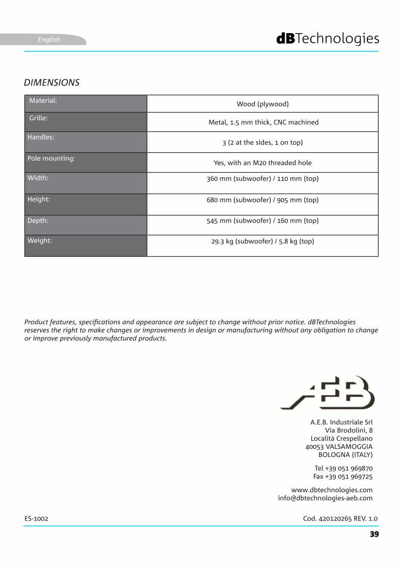
Product features, specifications and appearance are subject to change without prior notice. dBTechnologies reserves the right to make changes or improvements in design or manufacturing without any obligation to change or improve previously manufactured products.
A.E.B. Industriale SrlVia Brodolini, 8
Località Crespellano40053 VALSAMOGGIA
BOLOGNA (ITALY)
Tel +39 051 969870Fax +39 051 969725
English
Material: Wood (plywood)
Grille: Metal, 1.5 mm thick, CNC machined
Handles:3 (2 at the sides, 1 on top)
Pole mounting:Yes, with an M20 threaded hole
Width: 360 mm (subwoofer) / 110 mm (top)
Height: 680 mm (subwoofer) / 905 mm (top)
Depth: 545 mm (subwoofer) / 160 mm (top)
Weight: 29.3 kg (subwoofer) / 5.8 kg (top)

40
ES-1002 Code 420120265 REV. 1.0
INHALTSVERZEICHNIS
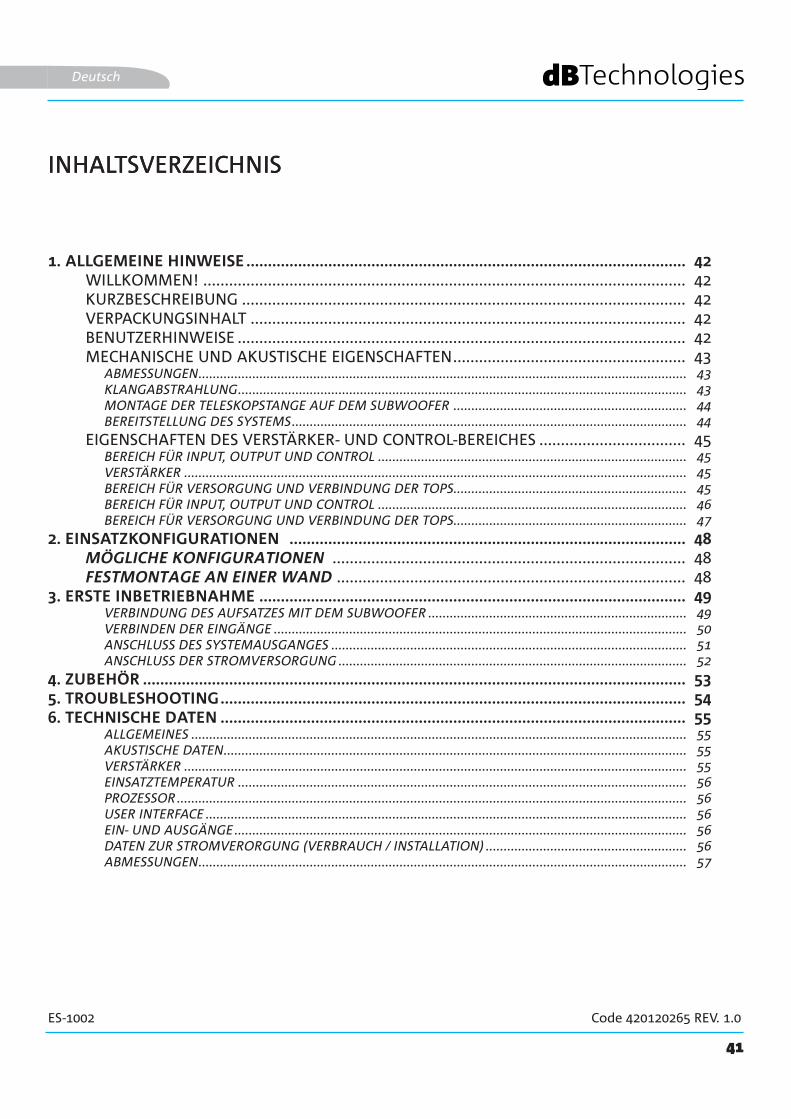
1. ALLGEMEINE HINWEISE ...................................................................................................... 42WILLKOMMEN! ................................................................................................................ 42KURZBESCHREIBUNG ....................................................................................................... 42VERPACKUNGSINHALT ..................................................................................................... 42BENUTZERHINWEISE ........................................................................................................ 42MECHANISCHE UND AKUSTISCHE EIGENSCHAFTEN ...................................................... 43
ABMESSUNGEN ........................................................................................................................................ 43KLANGABSTRAHLUNG ............................................................................................................................. 43MONTAGE DER TELESKOPSTANGE AUF DEM SUBWOOFER ................................................................. 44BEREITSTELLUNG DES SYSTEMS .............................................................................................................. 44
EIGENSCHAFTEN DES VERSTÄRKER- UND CONTROL-BEREICHES .................................. 45BEREICH FÜR INPUT, OUTPUT UND CONTROL ...................................................................................... 45VERSTÄRKER ............................................................................................................................................ 45BEREICH FÜR VERSORGUNG UND VERBINDUNG DER TOPS ................................................................. 45BEREICH FÜR INPUT, OUTPUT UND CONTROL ...................................................................................... 46BEREICH FÜR VERSORGUNG UND VERBINDUNG DER TOPS ................................................................. 47
2. EINSATZKONFIGURATIONEN ............................................................................................ 48MÖGLICHE KONFIGURATIONEN .................................................................................. 48FESTMONTAGE AN EINER WAND ................................................................................. 48
3. ERSTE INBETRIEBNAHME ................................................................................................... 49VERBINDUNG DES AUFSATZES MIT DEM SUBWOOFER ........................................................................ 49VERBINDEN DER EINGÄNGE ................................................................................................................... 50ANSCHLUSS DES SYSTEMAUSGANGES ................................................................................................... 51ANSCHLUSS DER STROMVERSORGUNG ................................................................................................. 52
4. ZUBEHÖR .............................................................................................................................. 535. TROUBLESHOOTING ............................................................................................................ 546. TECHNISCHE DATEN ............................................................................................................ 55
ALLGEMEINES .......................................................................................................................................... 55AKUSTISCHE DATEN ................................................................................................................................. 55VERSTÄRKER ............................................................................................................................................ 55EINSATZTEMPERATUR ............................................................................................................................. 56PROZESSOR .............................................................................................................................................. 56USER INTERFACE ...................................................................................................................................... 56EIN- UND AUSGÄNGE .............................................................................................................................. 56DATEN ZUR STROMVERORGUNG (VERBRAUCH / INSTALLATION) ........................................................ 56ABMESSUNGEN ........................................................................................................................................ 57
41
ES-1002 Code 420120265 REV. 1.0
INHALTSVERZEICHNIS
Deutsch

42
ES-1002 Code 420120265 REV. 1.0
1. ALLGEMEINE HINWEISE
WILLKOMMEN!
KURZBESCHREIBUNG
BENUTZERHINWEISE
Danke, dass Sie ein Produkt erworben haben, das von dBTechnologies in Italien entworfen und entwickelt wurde! Dieses aktive, vielseitige und ergonomische System ist das Ergebnis langjähriger Erfahrung im Bereich Klangwiedergabe, in das optimierte Lösungen im akustischen und elektronischen Bereich sowie bei der Materialauswahl Eingang fanden.
Das ES 1002 ist leistungsfähige, kompakte System der ES-Serie.Der aus Holz gefertigte, mit zwei 12-Zoll-Woofern ausgestattete Subwoofer und der in einer Curved Column Array-Konfiguration ausgelegte Aufsatz (acht 4-Zoll-Wandler aus Neodym) ermöglichen noch flexibleren Einsatz in vielfältigeren Umgebungen.Der Eingangsbereich und die Möglichkeit zur Weiterleitung an ein Zweitsystem machen das Produkt zusammen mit der Möglichkeit zur Verwendung eigener, voreingestellter DSPs sowohl geeignet für Live/DJ-Sets als auch für Konferenzen (PA-Anlage).Durch eine Reihe optionaler Zubehörteile erhält das Produkt eine einfachere, direktere Verwendungsmöglichkeiten. Hauptfeatures:
Damit Sie Ihr ES-1002 System optimal nutzen können, empfehlen wir:
• kompaktes, hochwertiges, leicht transportierbares System• optimierte Akustiklösungen zur Sicherstellung hoher Klangqualität in einem breiten Frequenzspektrum
und optimal verständlicher Sprachwiedergabe • Digitalverstärker der neuen Generation (900 W RMS) DIGIPRO G3.• 1 MIC/LINE-, 1 RCA-Stereo-Eingang
• den im Lieferumfang inbegriffenen Quick Start Guide sowie diese Bedienungsanleitung vollständig zu lesen und beide während der gesamten Lebensdauer des Produktes aufzubewahren.
• Registrierung des Produktes auf der Website http://www.dbtechnologies.com/de/home unter “SUPPORT”.• Aufbewahren des Einkaufsbeleges und der GARANTIE (Benutzerhandbuch, "Abschnitt 2").
Deutsch
VERPACKUNGSINHALT
• 1 Subwoofer ES1002S SUB• 1 montierbare Teleskopstange (mit M20-Gewinde-Endstück)• 1 Audiokabel (2,5 m) und 2 Kabelbinder• Sicherung für den Spannungsbereich 100-120V~• Stromversorgungskabel• Bedienungsunterlagen
Das Produkt wird in zwei separaten Verpackungen ausgeliefert:
VERPACKUNG 1
VERPACKUNG 2• 1 Säulenlautsprecher vom Typ ES1002TOP

43
ES-1002 Code 420120265 REV. 1.0
MECHANISCHE UND AKUSTISCHE EIGENSCHAFTEN
ABMESSUNGEN
KLANGABSTRAHLUNG
Das ES1002 System hat folgende Abmessungen:
SUBWOOFER: 360 mm x 680 mm x 545 mm
AUFSATZ (TOP): 110 mm x 905 mm x 160 mm
Die Klangabstrahlung des ES1002-Aufsatzes beträgt40° (vertikal) und 97°(horizontal). Asymmetrische vertikale Klangabstrahlung (+10°; -30°).
Deutsch
44
ES-1002 Code 420120265 REV. 1.0
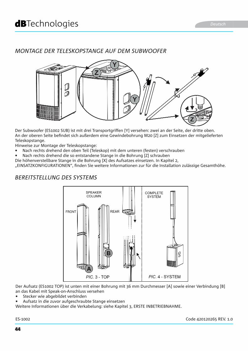
MONTAGE DER TELESKOPSTANGE AUF DEM SUBWOOFER
Der Subwoofer (ES1002 SUB) ist mit drei Transportgriffen [Y] versehen: zwei an der Seite, der dritte oben. An der oberen Seite befindet sich außerdem eine Gewindebohrung M20 [Z] zum Einsetzen der mitgelieferten Teleskopstange.Hinweise zur Montage der Teleskopstange:• Nach rechts drehend den oben Teil (Teleskop) mit dem unteren (festen) verschrauben• Nach rechts drehend die so entstandene Stange in die Bohrung [Z] schraubenDie höhenverstellbare Stange in die Bohrung [X] des Aufsatzes einsetzen. In Kapitel 2, „EINSATZKONFIGURATIONEN“, finden Sie weitere Informationen zur für die Installation zulässige Gesamthöhe.
Deutsch
BEREITSTELLUNG DES SYSTEMS
Der Aufsatz (ES1002 TOP) ist unten mit einer Bohrung mit 36 mm Durchmesser [A] sowie einer Verbindung [B] an das Kabel mit Speak-on-Anschluss versehen• Stecker wie abgebildet verbinden• Aufsatz in die zuvor aufgeschraubte Stange einsetzenWeitere Informationen über die Verkabelung: siehe Kapitel 3, ERSTE INBETRIEBNAHME.

45
ES-1002 Code 420120265 REV. 1.0
EIGENSCHAFTEN DES VERSTÄRKER- UND CONTROL-BEREICHES
Der Class-D-Digitalverstärker ist das Herzstück der ES-Serie. Das System funktioniert geräuschlos und ist mit einem eigenen DSP verbunden, das diverse Parameter regelt. Diese sind dank der Steuerungs-Schnittstelle voll konfigurierbar.Die Verstärkerleistung beträgt 900 W RMS.
Die Bedientafel des ES1002 verfügt über:
ACHTUNG!
• Bereich für Input, Output und Control• Bereich für Stromversorgung und
Verbindung des Aufsatzes
Deutsch
• Die hinteren Kühlrippen des Verstärkers nicht abdecken. Bei Überhitzung sinkt die Wiedergabelautstärke allmählich ab, bis die Modultemperatur stabil ist. Bei Wiedererreichen der richtigen Betriebstemperatur wird die Lautstärke automatisch wieder eingestellt.
• Keinesfalls versuchen, den Verstärker eigenmächtig zu öffnen.
• Bei Funktionsstörungen sofort die Stromversorgung unterbrechen, das Gerät vom Strom nehmen und eine autorisierte Reparaturwerkstatt kontaktieren.
• Das System ist mit einer vormontierten Sicherung ausgestattet, die im Spannungsbereich zwischen 220 und 240 V einsetzbar ist. Soll jedoch im Bereich 100-120 V operiert werden, bitte wie folgt vorgehen:1. Alle Anschlüsse einschließlich der
Stromversorgung vom Netz nehmen.2. 5 Minuten warten.3. Die Sicherung durch die in der
Ausstattung mitgelieferte für den Bereich 100-120 V ersetzen.
• Nur die mitgelieferten Kabel verwenden.
• Das Frontgitter dient dem Schutz des Produktes und darf nicht entfernt werden. Zur Vermeidung des Risikos von Strom-stößen bei versehentlicher Beschädigung oder Ersetzen des Schutzgitters (das durch den Kundendienst vorzunehmen ist), ist sofort die Stromversorgung zu unterbre-chen. Niemals das Gerät ans Stromnetz an-schließen, wenn das Schutzgitter entfernt wurde.
ACHTUNG!
BER
EIC
H F
ÜR
INPU
T, O
UT-
PUT
UN
D C
ON
TRO
LV
ERST
ÄR
KER
BER
EIC
H
FÜR
V
ERSO
R-
GU
NG
UN
D V
ERB
IND
UN
G
DER
TO
PS
46
ES-1002 Code 420120265 REV. 1.0
BEREICH FÜR INPUT, OUTPUT UND CONTROL
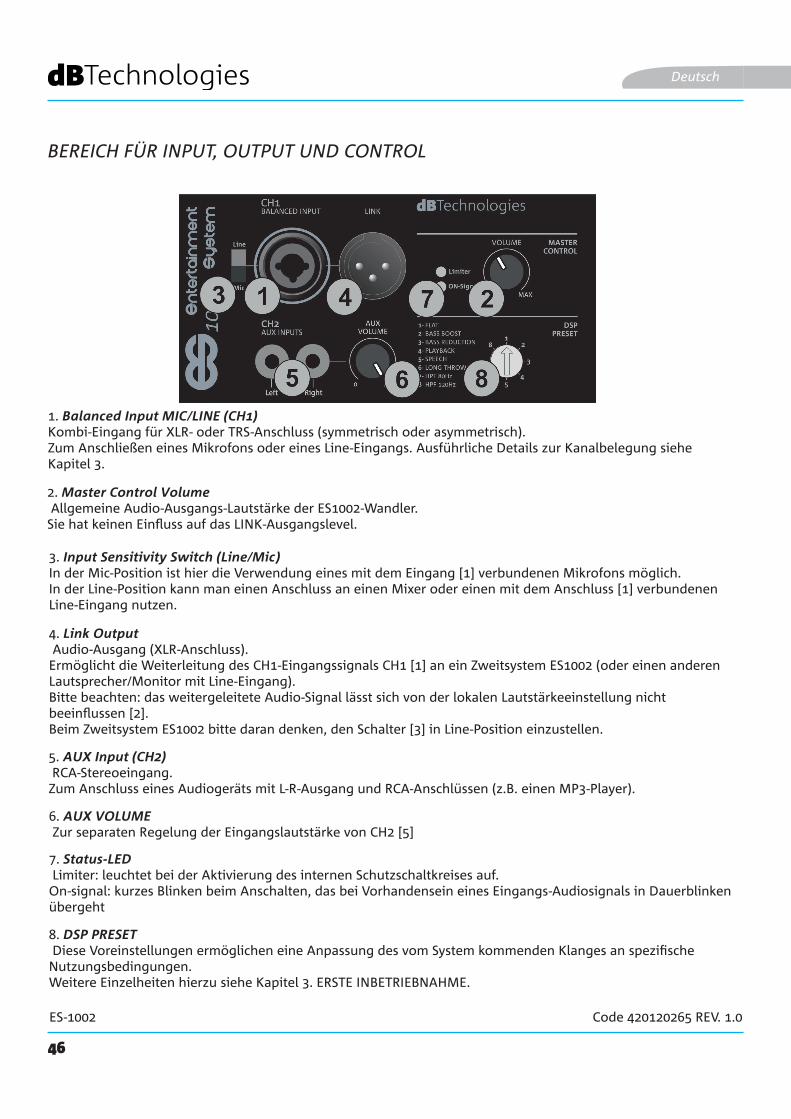
1. Balanced Input MIC/LINE (CH1) Kombi-Eingang für XLR- oder TRS-Anschluss (symmetrisch oder asymmetrisch). Zum Anschließen eines Mikrofons oder eines Line-Eingangs. Ausführliche Details zur Kanalbelegung siehe Kapitel 3.
Deutsch
2. Master Control Volume Allgemeine Audio-Ausgangs-Lautstärke der ES1002-Wandler.Sie hat keinen Einfluss auf das LINK-Ausgangslevel.
5. AUX Input (CH2) RCA-Stereoeingang.Zum Anschluss eines Audiogeräts mit L-R-Ausgang und RCA-Anschlüssen (z.B. einen MP3-Player).
3. Input Sensitivity Switch (Line/Mic) In der Mic-Position ist hier die Verwendung eines mit dem Eingang [1] verbundenen Mikrofons möglich.In der Line-Position kann man einen Anschluss an einen Mixer oder einen mit dem Anschluss [1] verbundenen Line-Eingang nutzen.
4. Link Output Audio-Ausgang (XLR-Anschluss).Ermöglicht die Weiterleitung des CH1-Eingangssignals CH1 [1] an ein Zweitsystem ES1002 (oder einen anderen Lautsprecher/Monitor mit Line-Eingang). Bitte beachten: das weitergeleitete Audio-Signal lässt sich von der lokalen Lautstärkeeinstellung nicht beeinflussen [2].Beim Zweitsystem ES1002 bitte daran denken, den Schalter [3] in Line-Position einzustellen.
6. AUX VOLUME Zur separaten Regelung der Eingangslautstärke von CH2 [5]
7. Status-LED Limiter: leuchtet bei der Aktivierung des internen Schutzschaltkreises auf.On-signal: kurzes Blinken beim Anschalten, das bei Vorhandensein eines Eingangs-Audiosignals in Dauerblinken übergeht
8. DSP PRESET Diese Voreinstellungen ermöglichen eine Anpassung des vom System kommenden Klanges an spezifische Nutzungsbedingungen.Weitere Einzelheiten hierzu siehe Kapitel 3. ERSTE INBETRIEBNAHME.

47
ES-1002 Code 420120265 REV. 1.0
10. MAINS INPUT Anschluss für VDE-Stecker. Zur Verbindung mit dem Stromnetz über das mitgelieferte Kabel.
9. TOP OUTPUT Anschluss für den Aufsatz ES1002TOP.
BEREICH FÜR VERSORGUNG UND VERBINDUNG DER TOPS
Deutsch
11. ON-OFF-SCHALTER (POWER) Zum Einschalten (Position "I") oder Ausschalten (Position "O") des Systems
12. NETZSICHERUNG Ort für die Netzsicherung (austauschbar im Fall von Beschädigung oder zum Betrieb im Spannungsbereich zwischen 100-120V~)
ACHTUNG!• An TOP OUTPUT-Anschlüsse [9] dürfen ausschließlich passive Geräte vom Typ ES1002TOP
angeschlossen werden!
48
ES-1002 Code 420120265 REV. 1.0
2. EINSATZKONFIGURATIONEN
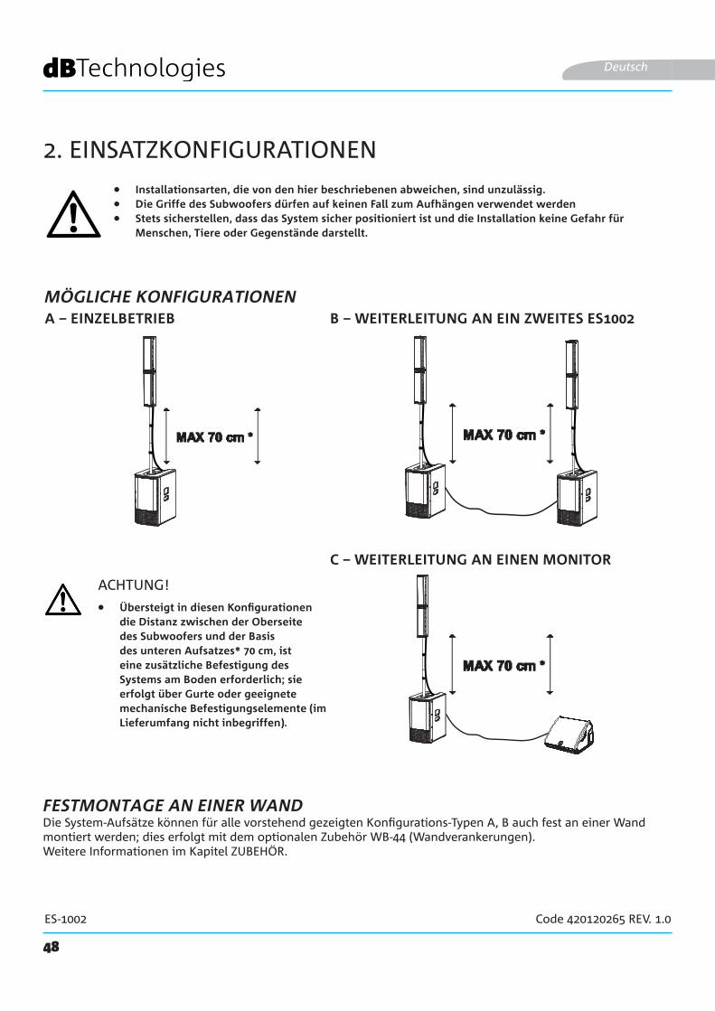
• Installationsarten, die von den hier beschriebenen abweichen, sind unzulässig.• Die Griffe des Subwoofers dürfen auf keinen Fall zum Aufhängen verwendet werden• Stets sicherstellen, dass das System sicher positioniert ist und die Installation keine Gefahr für
Menschen, Tiere oder Gegenstände darstellt.
B – WEITERLEITUNG AN EIN ZWEITES ES1002A – EINZELBETRIEB
Deutsch
ACHTUNG!
Die System-Aufsätze können für alle vorstehend gezeigten Konfigurations-Typen A, B auch fest an einer Wand montiert werden; dies erfolgt mit dem optionalen Zubehör WB-44 (Wandverankerungen).Weitere Informationen im Kapitel ZUBEHÖR.
FESTMONTAGE AN EINER WAND
• Übersteigt in diesen Konfigurationen die Distanz zwischen der Oberseite des Subwoofers und der Basis des unteren Aufsatzes* 70 cm, ist eine zusätzliche Befestigung des Systems am Boden erforderlich; sie erfolgt über Gurte oder geeignete mechanische Befestigungselemente (im Lieferumfang nicht inbegriffen).
C – WEITERLEITUNG AN EINEN MONITOR
MÖGLICHE KONFIGURATIONEN

49
ES-1002 Code 420120265 REV. 1.0
3. ERSTE INBETRIEBNAHME
VERBINDUNG DES AUFSATZES MIT DEM SUBWOOFER
Deutsch
Nach der Montage des Aufsatzes auf die Stange gemäß Anweisungen im entsprechenden Abschnitt muss der Anschluss an den Subwoofer erfolgen:
• Bitte sicherstellen, dass der Aufsatz auf der zuvor auf den Subwoofer montierten Teleskopstange korrekt eingesetzt ist
• Hierzu das mitgelieferte 2,5 m lange Kabel verwenden.• Den Aufsatz wie abgebildet mit
dem unteren Verschluss verbinden• Verbinden des "Sub" am TOP OUTPUT-Anschluss [9] • Zur Befestigung des Kabels um die Teleskopstange
die mitgelieferten Clips verwenden
RL
RL
STEREO INPUT
50
ES-1002 Code 420120265 REV. 1.0
VERBINDEN DER EINGÄNGE
Deutsch
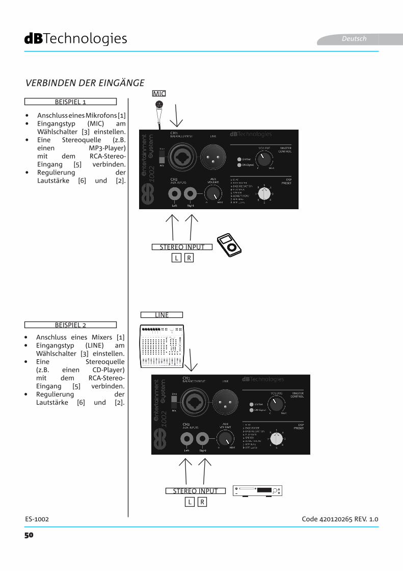
• Anschluss eines Mikrofons [1]• Eingangstyp (MIC) am
Wählschalter [3] einstellen.• Eine Stereoquelle (z.B.
einen MP3-Player) mit dem RCA-Stereo-Eingang [5] verbinden.
• Regulierung der Lautstärke [6] und [2].
MIC
STEREO INPUT
BEISPIEL 1
LINE
BEISPIEL 2
• Anschluss eines Mixers [1]• Eingangstyp (LINE) am
Wählschalter [3] einstellen.• Eine Stereoquelle
(z.B. einen CD-Player) mit dem RCA-Stereo-Eingang [5] verbinden.
• Regulierung der Lautstärke [6] und [2].

51
ES-1002 Code 420120265 REV. 1.0
MONITORES 1002
Deutsch
ANSCHLUSS DES SYSTEMAUSGANGES
Für Audio-Weiterleitung an ein zweites ES1002-System:
• Den Ausgangsstecker [4] des ersten ES1002 mit dem CH1-Eingang eines Zweitsystems verbinden.
• Eingangstyp (LINE) am Wählschalter [3] des Zweitsystems einstellen.
SYSTEM 1 SYSTEM 2
KONFIGURATION FÜR WEITERLEITUNGEN
WEITERLEITUNG AN EINEN MONITORAUSGANG
XLR
XLR
Zur Audio-Weiterleitung an einen Monitor:
• Den Ausgangsstecker [4] des ersten ES1002 mit einem Monitor-Eingang verbinden.
• Sofern möglich, den Eingangstyp (LINE) am evtl. am Monitor vorhandenen Wählschalter einstellen.
52
ES-1002 Code 420120265 REV. 1.0
ANSCHLUSS DER STROMVERSORGUNG
Deutsch
STROMVERSORGUNG(VDE-STECKER)
• Verbinden des VDE-Steckers des mitgelieferten Kabels mit "MAINS INPUT" [10.
• Den Stecker in eine geerdete Steckdose stecken. • Den POWER-Knopf [11] in "I"-Position bringen.
DP-ES1203DO-ES212
53
ES-1002 Code 420120265 REV. 1.0
WB-44
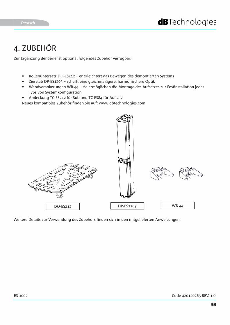
Zur Ergänzung der Serie ist optional folgendes Zubehör verfügbar:
• Rollenuntersatz DO-ES212 – er erleichtert das Bewegen des demontierten Systems• Zierstab DP-ES1203 – schafft eine gleichmäßigere, harmonischere Optik • Wandverankerungen WB-44 – sie ermöglichen die Montage des Aufsatzes zur Festinstallation jedes
Typs von Systemkonfiguration• Abdeckung TC-ES212 für Sub und TC-ES84 für AufsatzNeues kompatibles Zubehör finden Sie auf: www.dbtechnologies.com.
Deutsch
4. ZUBEHÖR
Weitere Details zur Verwendung des Zubehörs finden sich in den mitgelieferten Anweisungen.
54
ES-1002 Code 420120265 REV. 1.0
5. TROUBLESHOOTING
1. Überprüfen, ob das Gerät korrekt mit der Stromversorgung verbunden ist.2. Überprüfen, ob das Stromversorgungskabel mit VDE-Stecker korrekt eingesteckt und der Anschalter
auf ON-Position ist.
1. Überprüfen, ob die Eingangsverbindung des Audio-Signals korrekt vorgenommen wurde.2. Überprüfen, ob die verwendeten Kabel beschädigt sind.3. Verbindungen zwischen Aufsatz und Subwoofer überprüfen.4. Überprüfen, ob der Mixer oder die Audioquelle eingeschaltet ist und eindeutig das Vorhandensein
eines Ausgangssignals anzeigt.5. Überprüfen, ob die Einstellungen der Eingangspegel, der Eingangs- und Ausgangsart korrekt gewählt
wurden.
1. Überprüfen, ob die eingesetzten Kabel Beschädigungen aufweisen; ist dies der Fall, sind diese zu ersetzen (ein beschädigtes Kabel kann zu Signalverlust oder -Veränderung führen).
2. Überprüfen, ob die Einstellungen der Eingangspegel, der Eingangs- und Ausgangsart korrekt gewählt wurden.
System lässt sich nicht anschalten:
Das Gerät lässt sich zwar anschalten, doch es kommt kein Klang:
Der aus dem Gerät kommende Klang ist zu leise oder verzerrt:
Deutsch

55
ES-1002 Code 420120265 REV. 1.0
6. TECHNISCHE DATEN
ALLGEMEINES
AKUSTISCHE DATEN
VERSTÄRKER
Typologie: Mono-System (Doppelverstärkung)
Deutsch
Frequenzgang [-10dB]: 43 -20000 Hz
Frequenzgang [-6dB]: 56 - 18000 Hz
Max. SPL (1 m):130,7 dB
MF-HF Midwoofer: 8 x 4"
MF-HF Voicecoil:25 mm
LF-Woofer:2 x 12" (Subwoofer)
LF Voicecoil:64 mm
Übergangsfrequenz:160 Hz (24 dB/oct)
Richtwirkung: Vertikal asymmetrisch
Abdeckung (HxV):97° x 40° [+10°;-30°]
Typologie: DIGIPRO G3
Verstärkungsklasse Class D
Stromversorgung1 x VDE
RMS-Verstärkerleistung: 900 W
56
ES-1002 Code 420120265 REV. 1.0
PROZESSOR
EIN- UND AUSGÄNGE
Deutsch
USER INTERFACE
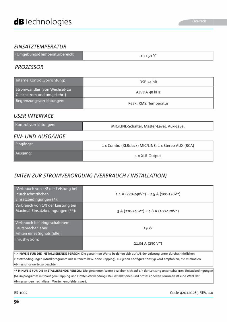
Verbrauch von 1/8 der Leistung bei durchschnittlichen Einsatzbedingungen (*):
1.4 A (220-240V~) – 2.5 A (100-120V~)
Verbrauch von 1/3 der Leistung bei Maximal-Einsatzbedingungen (**): 3 A (220-240V~) – 4.8 A (100-120V~)
Verbrauch bei eingeschaltetem Lautsprecher, aber Fehlen eines Signals (idle):
19 W
Inrush-Strom:21.04 A (230 V~)
DATEN ZUR STROMVERORGUNG (VERBRAUCH / INSTALLATION)
* HINWEIS FÜR DIE INSTALLIERENDE PERSON: Die genannten Werte beziehen sich auf 1/8 der Leistung unter durchschnittlichen
Einsatzbedingungen (Musikprogramm mit seltenem bzw. ohne Clipping). Für jeden Konfigurationstyp wird empfohlen, die minimalen
Abmessungswerte zu beachten.
** HINWEIS FÜR DIE INSTALLIERENDE PERSON: Die genannten Werte beziehen sich auf 1/3 der Leistung unter schweren Einsatzbedingungen
(Musikprogramm mit häufigem Clipping und Limiter-Verwendung). Bei Installationen und professionellen Tourneen ist eine Wahl der
Abmessungen nach diesen Werten empfehlenswert.
Interne Kontrollvorrichtung: DSP 24 bit
Stromwandler (von Wechsel- zu Gleichstrom und umgekehrt)
AD/DA 48 kHz
Begrenzungsvorrichtungen:Peak, RMS, Temperatur
Kontrollvorrichtungen: MIC/LINE-Schalter, Master-Level, Aux-Level
Eingänge: 1 x Combo (XLR/Jack) MIC/LINE, 1 x Stereo AUX (RCA)
Ausgang:1 x XLR Output
EINSATZTEMPERATUR(Umgebungs-)Temperaturbereich: -10 +50 °C
57
ES-1002 Code 420120265 REV. 1.0
ABMESSUNGEN
Die Eigenschaften, spezifischen Daten und Optik des Produktes können ohne vorherige Ankündigung Änderungen unterworfen sein. dBTechnologies behält sich das Recht vor, Änderungen und Verbesserungen an Design und der Verarbeitung vorzunehmen, ohne dabei dazu verpflichtet zu sein, auch zuvor realisierte Produkte zu verändern und zu verbessern.
A.E.B. Industriale SrlVia Brodolini, 8
Località Crespellano40053 VALSAMOGGIA
BOLOGNA (ITALIA)
Tel. +39 051 969870Fax +39 051 969725
Deutsch
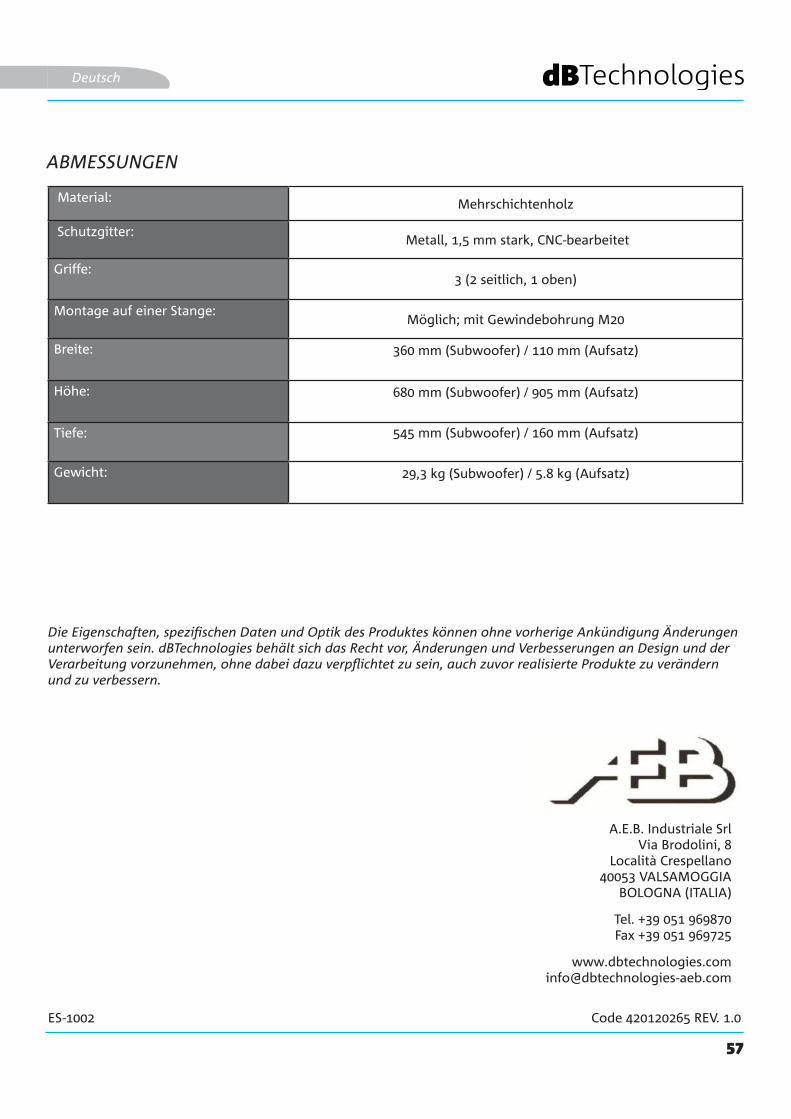
Material: Mehrschichtenholz
Schutzgitter: Metall, 1,5 mm stark, CNC-bearbeitet
Griffe:3 (2 seitlich, 1 oben)
Montage auf einer Stange:Möglich; mit Gewindebohrung M20
Breite: 360 mm (Subwoofer) / 110 mm (Aufsatz)
Höhe: 680 mm (Subwoofer) / 905 mm (Aufsatz)
Tiefe: 545 mm (Subwoofer) / 160 mm (Aufsatz)
Gewicht: 29,3 kg (Subwoofer) / 5.8 kg (Aufsatz)

58
ES-1002 Cod. 420120265 REV. 1.0
TABLE DES MATIÈRES
1. GÉNÉRALITÉS ........................................................................................................................ 60BIENVENUE ! ..................................................................................................................... 60INTRODUCTION ................................................................................................................ 60CONTENU DE L'EMBALLAGE ............................................................................................ 60RÉFÉRENCES POUR L'UTILISATEUR .................................................................................. 60CARACTÉRISTIQUES MÉCANIQUES ET ACOUSTIQUES ................................................... 61
DIMENSIONS ............................................................................................................................................ 61COUVERTURE SONORE ........................................................................................................................... 61MONTAGE DU MÂT TÉLESCOPIQUE FOURNI SUR LE SUBWOOFER ..................................................... 62COMPLÉMENT DU SYSTÈME ................................................................................................................... 62
CARACTÉRISTIQUES DE LA SECTION D'AMPLIFICATION ET DE CONTRÔLE .................. 63SECTION D'ENTRÉE, DE SORTIE ET DE CONTRÔLE................................................................................. 63AMPLIFICATEUR ....................................................................................................................................... 63SECTION D'ALIMENTATION ET DE CONNEXION DES TOPS ................................................................... 63SECTION D'ENTRÉE, DE SORTIE ET DE CONTRÔLE................................................................................. 64SECTION D'ALIMENTATION ET DE CONNEXION DES TOPS ................................................................... 65
2. CONFIGURATIONS D'UTILISATION .................................................................................. 66CONFIGURATIONS AU SOL ........................................................................................... 66INSTALLATION MURALE FIXE ....................................................................................... 66
3. PREMIER ALLUMAGE ........................................................................................................... 67CONNEXION DU TOP AU SUBWOOFER ................................................................................................. 67CONNEXION DES ENTRÉES ...................................................................................................................... 68CONNEXION DE LA SORTIE DU SYSTÈME .............................................................................................. 69CONNEXION DE L'ALIMENTATION ÉLECTRIQUE .................................................................................... 70
4. ACCESSOIRES ........................................................................................................................ 715. DÉPANNAGE ......................................................................................................................... 726. SPÉCIFICATIONS TECHNIQUES ........................................................................................... 73
GÉNÉRALES .............................................................................................................................................. 73DONNÉES ACOUSTIQUES ........................................................................................................................ 73AMPLIFICATEUR ....................................................................................................................................... 73TEMPÉRATURE D'UTILISATION ................................................................................................................ 74PROCESSEUR ............................................................................................................................................ 74INTERFACE UTILISATEUR ......................................................................................................................... 74ENTRÉES ET SORTIES................................................................................................................................ 74SPÉCIFICATIONS D'ALIMENTATION (CONSOMMATION / INSTALLATION) ............................................. 74DIMENSIONS ............................................................................................................................................ 75
59
ES-1002 Cod. 420120265 REV. 1.0
TABLE DES MATIÈRES
Français
60
ES-1002 Cod. 420120265 REV. 1.0
1. GÉNÉRALITÉS
BIENVENUE !
INTRODUCTION
RÉFÉRENCES POUR L'UTILISATEUR
Merci d'avoir acheté un produit conçu et développé en Italie par dBTechnologies ! À la fois actif, polyvalent et ergonomique, ce système est le fruit d'une longue expérience dans le domaine de la diffusion sonore. Ce système fait appel à des solutions optimisées non seulement dans les domaines de l'acoustique et de l'électronique, mais également dans le choix des matériaux.
ES 1002 représente le fleuron puissant et compact de la série ES.Le subwoofer en bois, équipé de 2 woofers de 12", et le top, conçu en configuration Curved Column Array (8 transducteurs 4” en néodyme) permettent une polyvalence remarquable dans différents environnements d'utilisation.La section d'entrées et la possibilité de relance vers un second système, ainsi que la possibilité d'utiliser des DSP préréglages dédiés, le rendent efficace pour une utilisation live/dj set, comme pour les installations PA de conférences.Plusieurs accessoires optionnels accompagnent le produit pour une utilisation plus simple et immédiate. Caractéristiques principales du système :
Pour utiliser au mieux votre système ES-1002, on ne saurait trop recommander de :
• système compact et de qualité, facilement transportable• solutions acoustiques optimisées offrant une qualité de son optimale dans une gamme de fréquences
très large et une reproduction parfaitement intelligible de la voix parlée • amplificateur numérique de la nouvelle génération (900 W RMS) DIGIPRO G3.• 1 entrée MIC/LINE, 1 entrée stéréo RCA
• consulter le guide rapide « quick start » inclus dans l'emballage, ainsi que de lire attentivement et complètement le présent manuel d'utilisation et de le conserver soigneusement pour toute la durée de vie du produit et pour toute consultation future.
• enregistrer le produit sur le site http://www.dbtechnologies.com/fr/page-d-accueil dans la section « ASSISTANCE ».
• conserver la preuve d'achat et la GARANTIE (Manuel d'utilisation « section 2 »).
Français
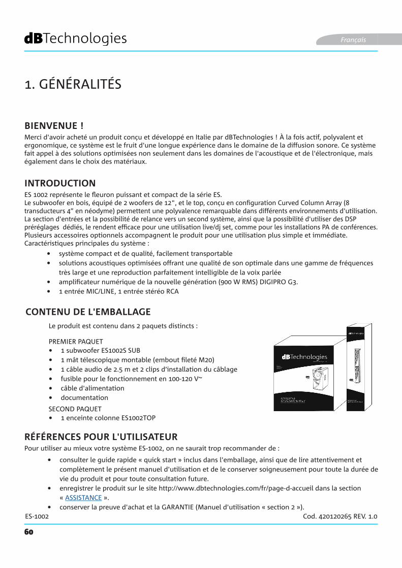
CONTENU DE L'EMBALLAGE
• 1 subwoofer ES1002S SUB• 1 mât télescopique montable (embout fileté M20)• 1 câble audio de 2.5 m et 2 clips d’installation du câblage• fusible pour le fonctionnement en 100-120 V~• câble d'alimentation• documentation
Le produit est contenu dans 2 paquets distincts :
PREMIER PAQUET
SECOND PAQUET• 1 enceinte colonne ES1002TOP

61
ES-1002 Cod. 420120265 REV. 1.0
CARACTÉRISTIQUES MÉCANIQUES ET ACOUSTIQUES
DIMENSIONS
COUVERTURE SONORE
Le système ES1002 mesure :
SUBWOOFER : 360 mm x 680 mm x 545 mm
TOP : 110 mm x 905 mm x 160 mm
La couverture sonore du top de ES1002est de 40° (verticale) et de 97° (horizontale). La couverture verticale est asymétrique (+10° ; -30°).
Français
62
ES-1002 Cod. 420120265 REV. 1.0
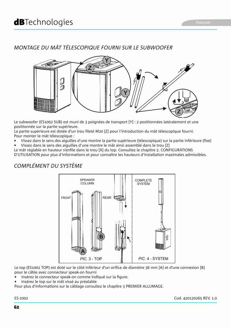
MONTAGE DU MÂT TÉLESCOPIQUE FOURNI SUR LE SUBWOOFER
Le subwoofer (ES1002 SUB) est muni de 3 poignées de transport [Y] : 2 positionnées latéralement et une positionnée sur la partie supérieure. La partie supérieure est dotée d’un trou fileté M20 [Z] pour l'introduction du mât télescopique fourni.Pour monter le mât télescopique :• Vissez dans le sens des aiguilles d'une montre la partie supérieure (télescopique) sur la partie inférieure (fixe)• Vissez dans le sens des aiguilles d'une montre le mât ainsi assemblé dans le trou [Z]Le mât réglable en hauteur s’enfile dans le trou [X] du top. Consultez le chapitre 2. CONFIGURATIONS D’UTILISATION pour plus d'informations et pour connaître les hauteurs d'installation maximales admissibles.
Français
COMPLÉMENT DU SYSTÈME
Le top (ES1002 TOP) est doté sur le côté inférieur d’un orifice de diamètre 36 mm [A] et d’une connexion [B] pour le câble avec connecteur speak-on fourni• Insérez le connecteur speak-on comme indiqué sur la figure.• Insérez le top sur le mât vissé au préalablePour plus d’informations sur le câblage consultez le chapitre 3 PREMIER ALLUMAGE.
63
ES-1002 Cod. 420120265 REV. 1.0
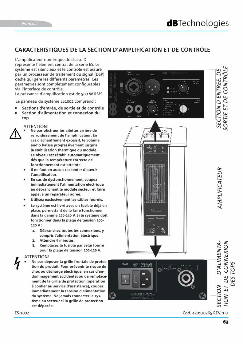
CARACTÉRISTIQUES DE LA SECTION D'AMPLIFICATION ET DE CONTRÔLE
L'amplificateur numérique de classe D représente l'élément central de la série ES. Le système est silencieux et le contrôle est assuré par un processeur de traitement du signal (DSP) dédié qui gère les différents paramètres. Ces paramètres sont complètement configurables via l'interface de contrôle.La puissance d'amplification est de 900 W RMS.
Le panneau du système ES1002 comprend :
ATTENTION!
• Sections d'entrée, de sortie et de contrôle• Section d'alimentation et connexion du
top
Français
• Ne pas obstruer les ailettes arrière de refroidissement de l'amplificateur. En cas d'échauffement excessif, le volume audio baisse progressivement jusqu'à la stabilisation thermique du module. Le niveau est rétabli automatiquement dés que la température correcte de fonctionnement est atteinte.
• Il ne faut en aucun cas tenter d'ouvrir l'amplificateur.
• En cas de dysfonctionnement, coupez immédiatement l'alimentation électrique en débranchant le module secteur et faire appel à un réparateur agréé.
• Le système est livré avec un fusible déjà en place, permettant de le faire fonctionner dans la gamme 220-240 V. Si le système doit fonctionner dans la plage de tension 100-120 V :
1. Débranchez toutes les connexions, y compris l'alimentation électrique.
2. Attendre 5 minutes.3. Remplacez le fusible par celui fourni
pour la plage de tension 100-120 V.
• Utilisez exclusivement les câbles fournis.
• Ne pas déposer la grille frontale de protec-tion du produit. Pour prévenir le risque de choc ou décharge électrique, en cas d'en-dommagement accidentel ou de remplace-ment de la grille de protection (opération à confier au service d'assistance), coupez immédiatement la tension d'alimentation du système. Ne jamais connecter le sys-tème au secteur si la grille de protection est déposée.
ATTENTION!
SEC
TIO
N D
'EN
TRÉE
, DE
SOR
TIE
ET D
E C
ON
TRÔ
LEA
MPL
IFIC
ATE
UR
SEC
TIO
N
D'A
LIM
ENTA
-TI
ON
ET
DE
CO
NN
EXIO
N
DES
TO
PS

64
ES-1002 Cod. 420120265 REV. 1.0
SECTION D'ENTRÉE, DE SORTIE ET DE CONTRÔLE
1. Balanced Input MIC/LINE (CH1) Entrée combo pour connecteur XLR ou TRS (symétrique ou asymétrique). Il permet la connexion d'un microphone ou d'une entrée ligne. Pour les détails sur le réglage du canal, voir le chapitre 3.
Français
2. Master Control Volume Volume général de sortie audio des transducteurs de ES1002.N’influence pas le niveau de la sortie LINK.
5. AUX Input (CH2) Entrée stéréo RCA.Permet de connecter un périphérique audio avec une sortie L-R et des connecteurs RCA (par exemple un lecteur MP3).
3. Input sensitivity switch (Line/Mic) Il permet, en position Mic, d'utiliser un microphone connecté à l'entrée [1].En position Line, il permet d’utiliser une connexion à une table de mixage ou une entrée de ligne reliée au connecteur [1].
4. Link Output Sortie audio (connecteur XLR).Permet de relancer le signal d'entrée CH1 [1] vers un second système ES1002 (ou vers une autre enceinte/moniteur équipés d'une entrée de type « Line »). Notez que le signal audio relancé n'est pas affecté par le contrôle du volume local [2].Sur le deuxième système ES1002, n'oubliez pas de placer le commutateur [3] sur la position « Line ».
6. AUX VOLUME Permet de régler séparément le volume d'entrée CH2 [5]
7. LED d’état Limiter : il s'allume en cas d'intervention du circuit de protection interne.On-signal : bref clignotement au démarrage, intermittent pour signaler la présence d'un signal audio entrant
8. DSP PRESET Préréglages qui permettent d'adapter le son émis par le système à des conditions d'utilisation spécifiques.Pour plus d’informations consultez le chapitre 3 PREMIER ALLUMAGE.
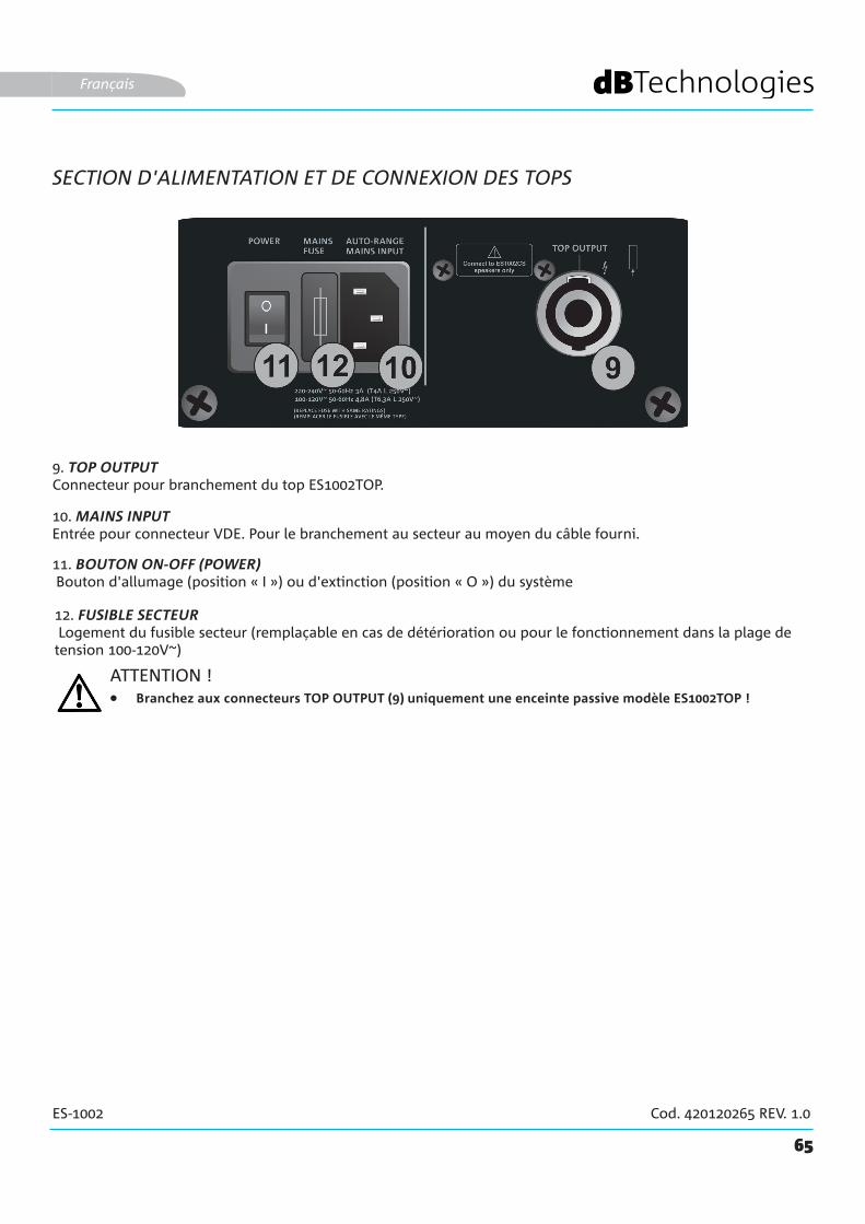
65
ES-1002 Cod. 420120265 REV. 1.0
10. MAINS INPUT Entrée pour connecteur VDE. Pour le branchement au secteur au moyen du câble fourni.
9. TOP OUTPUT Connecteur pour branchement du top ES1002TOP.
SECTION D'ALIMENTATION ET DE CONNEXION DES TOPS
Français
11. BOUTON ON-OFF (POWER) Bouton d'allumage (position « I ») ou d'extinction (position « O ») du système
12. FUSIBLE SECTEUR Logement du fusible secteur (remplaçable en cas de détérioration ou pour le fonctionnement dans la plage de tension 100-120V~)
ATTENTION !• Branchez aux connecteurs TOP OUTPUT (9) uniquement une enceinte passive modèle ES1002TOP !
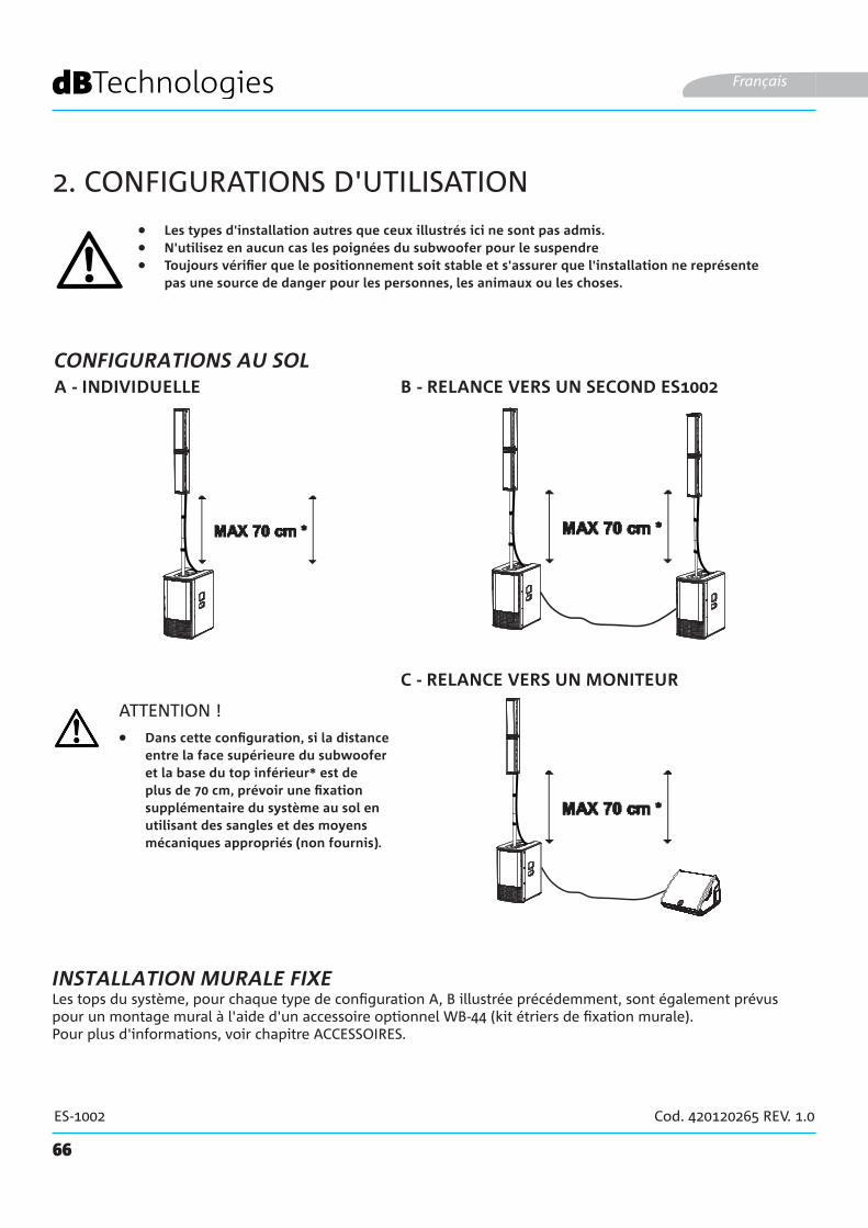
66
ES-1002 Cod. 420120265 REV. 1.0
2. CONFIGURATIONS D'UTILISATION
• Les types d'installation autres que ceux illustrés ici ne sont pas admis.• N'utilisez en aucun cas les poignées du subwoofer pour le suspendre• Toujours vérifier que le positionnement soit stable et s'assurer que l'installation ne représente
pas une source de danger pour les personnes, les animaux ou les choses.
B - RELANCE VERS UN SECOND ES1002A - INDIVIDUELLE
Français
ATTENTION !
Les tops du système, pour chaque type de configuration A, B illustrée précédemment, sont également prévus pour un montage mural à l'aide d'un accessoire optionnel WB-44 (kit étriers de fixation murale).Pour plus d'informations, voir chapitre ACCESSOIRES.
INSTALLATION MURALE FIXE
• Dans cette configuration, si la distance entre la face supérieure du subwoofer et la base du top inférieur* est de plus de 70 cm, prévoir une fixation supplémentaire du système au sol en utilisant des sangles et des moyens mécaniques appropriés (non fournis).
C - RELANCE VERS UN MONITEUR
CONFIGURATIONS AU SOL
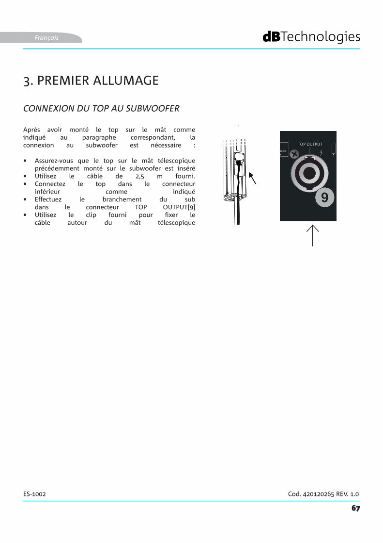
67
ES-1002 Cod. 420120265 REV. 1.0
3. PREMIER ALLUMAGE
CONNEXION DU TOP AU SUBWOOFER
Français
Après avoir monté le top sur le mât comme indiqué au paragraphe correspondant, la connexion au subwoofer est nécessaire :
• Assurez-vous que le top sur le mât télescopique précédemment monté sur le subwoofer est inséré
• Utilisez le câble de 2,5 m fourni.• Connectez le top dans le connecteur
inférieur comme indiqué• Effectuez le branchement du sub
dans le connecteur TOP OUTPUT[9] • Utilisez le clip fourni pour fixer le
câble autour du mât télescopique

RL
RL
STEREO INPUT
68
ES-1002 Cod. 420120265 REV. 1.0
CONNEXION DES ENTRÉES
Français
• Connectez un microphone au connecteur [1]
• Réglez le type d'entrée (MIC) sur le sélecteur [3].
• Connectez une source stéréo (par exemple un lecteur MP3) à l'entrée stéréo RCA [5].
• Réglez les volumes [6] et [2].
MIC
STEREO INPUT
PREMIER EXEMPLE
LINE
DEUXIÈME EXEMPLE
• Connectez une table de mixage au connecteur [1]
• Réglez le type d'entrée (LINE) sur le sélecteur [3].
• Connectez une source stéréo (par exemple un lecteur CD) à l'entrée stéréo RCA [5].
• Réglez les volumes [6] et [2].
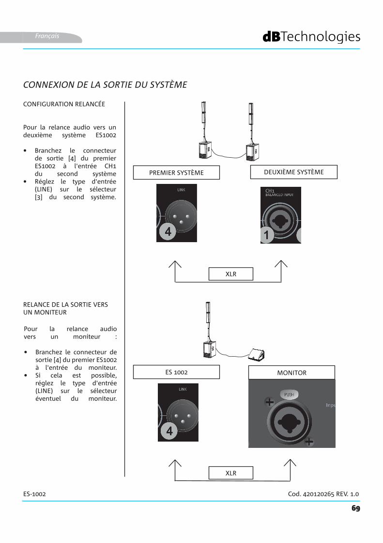
69
ES-1002 Cod. 420120265 REV. 1.0
MONITORES 1002
Français
CONNEXION DE LA SORTIE DU SYSTÈME
Pour la relance audio vers un deuxième système ES1002
• Branchez le connecteur de sortie [4] du premier ES1002 à l'entrée CH1 du second système
• Réglez le type d'entrée (LINE) sur le sélecteur [3] du second système.
PREMIER SYSTÈME DEUXIÈME SYSTÈME
CONFIGURATION RELANCÉE
RELANCE DE LA SORTIE VERS UN MONITEUR
XLR
XLR
Pour la relance audio vers un moniteur :
• Branchez le connecteur de sortie [4] du premier ES1002 à l'entrée du moniteur.
• Si cela est possible, réglez le type d'entrée (LINE) sur le sélecteur éventuel du moniteur.

70
ES-1002 Cod. 420120265 REV. 1.0
CONNEXION DE L'ALIMENTATION ÉLECTRIQUE
Français
ALIMENTATION(CONNECTEUR VDE)
• Raccordez le connecteur VDE du câble fourni à « MAINS INPUT » [10].
• Insérez la fiche dans une prise pourvue d'un conducteur de terre.
• Pressez le sélecteur POWER [11] sur la position « I ».
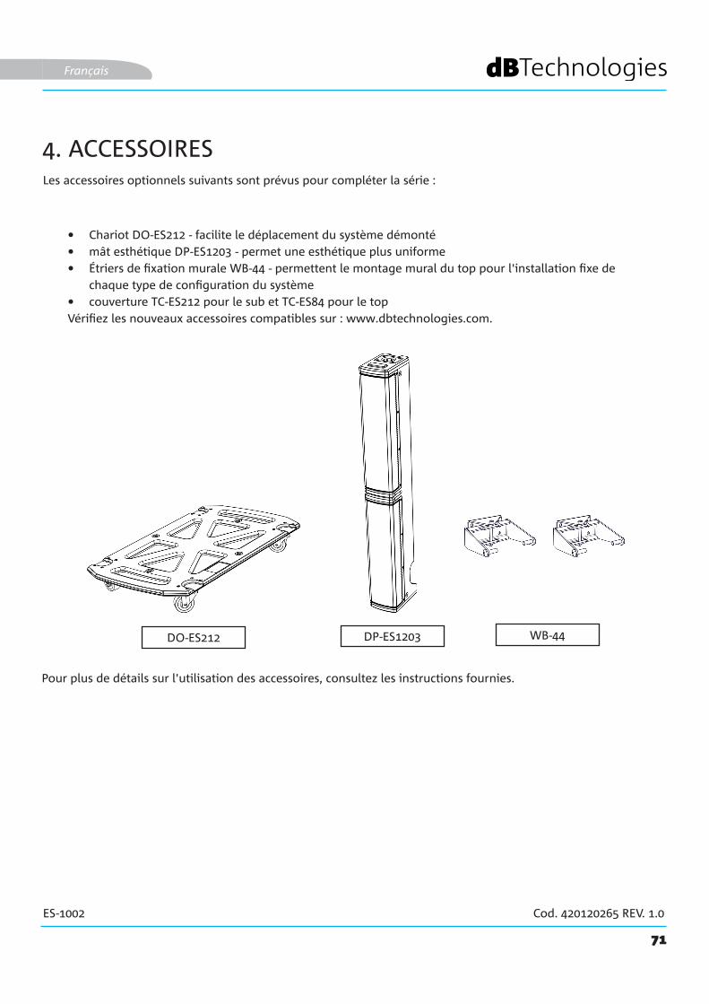
DP-ES1203DO-ES212
71
ES-1002 Cod. 420120265 REV. 1.0
WB-44
Les accessoires optionnels suivants sont prévus pour compléter la série :
• Chariot DO-ES212 - facilite le déplacement du système démonté• mât esthétique DP-ES1203 - permet une esthétique plus uniforme • Étriers de fixation murale WB-44 - permettent le montage mural du top pour l'installation fixe de
chaque type de configuration du système• couverture TC-ES212 pour le sub et TC-ES84 pour le topVérifiez les nouveaux accessoires compatibles sur : www.dbtechnologies.com.
Français
4. ACCESSOIRES
Pour plus de détails sur l'utilisation des accessoires, consultez les instructions fournies.
72
ES-1002 Cod. 420120265 REV. 1.0
5. DÉPANNAGE
1. Vérifiez l’alimentation électrique en amont de l'installation.2. Vérifiez que le câble d'alimentation avec connecteur VDE est correctement branché, avec le sélecteur
d'allumage positionné sur ON.
1. Vérifiez que la connexion en entrée du signal audio est correctement effectuée.2. Vérifiez que les câbles utilisés ne sont pas endommagés.3. Vérifiez les connexions entre le top et le subwoofer.4. Vérifiez que la table de mixage ou la source audio est allumée et indique clairement la présence de
signal en sortie.5. Vérifiez que les paramétrages des niveaux d'entrée, types d'entrée et de sortie sont bien adaptés.
1. Vérifiez que les câbles utilisés ne sont pas endommagés ; dans le cas contraire, les remplacer (un câble abîmé peut entraîner une perte ou altération du signal).
2. Vérifiez que les paramétrages des niveaux d'entrée, types d'entrée et de sortie sont bien adaptés.
Le système ne s'allume pas :
L’enceinte s'allume mais n'émet aucun son :
L’enceinte émet un son insuffisant ou distordu :
Français
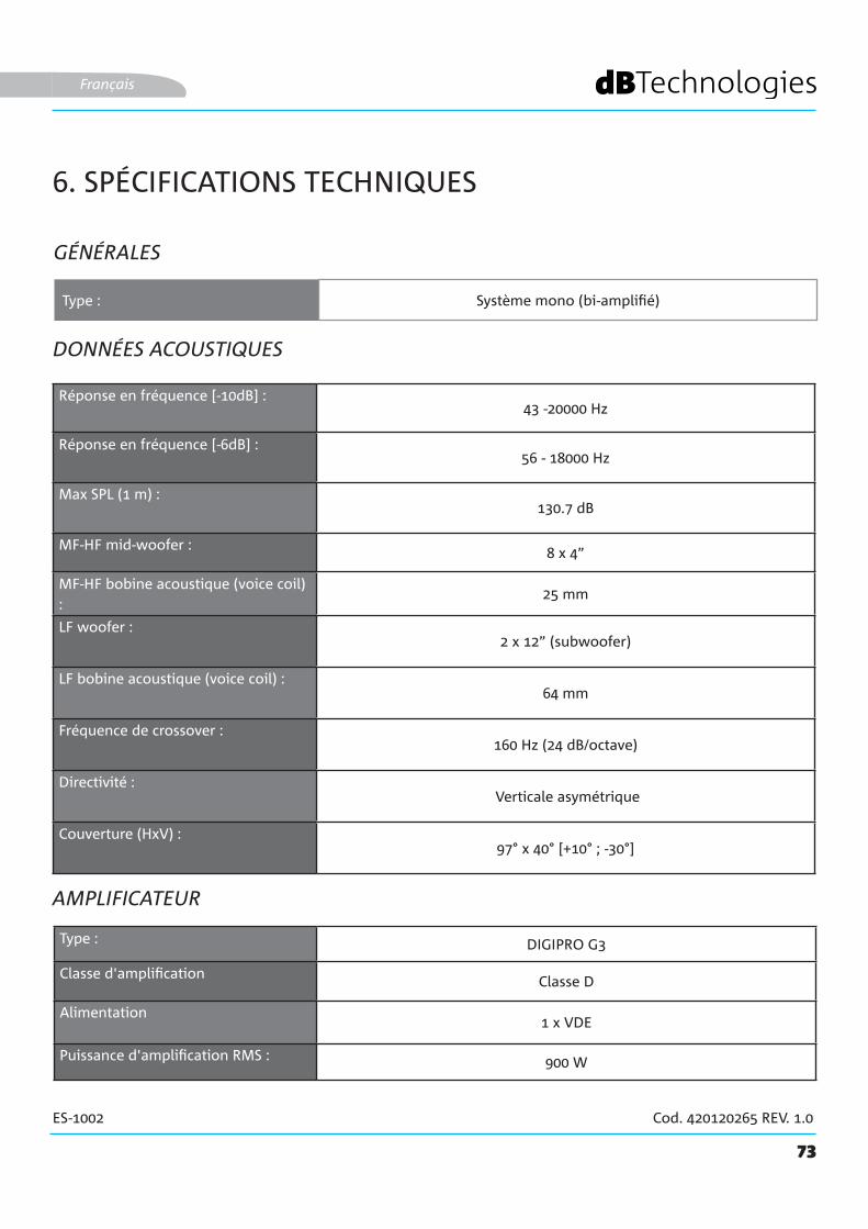
73
ES-1002 Cod. 420120265 REV. 1.0
6. SPÉCIFICATIONS TECHNIQUES
GÉNÉRALES
DONNÉES ACOUSTIQUES
AMPLIFICATEUR
Type : Système mono (bi-amplifié)
Français
Réponse en fréquence [-10dB] : 43 -20000 Hz
Réponse en fréquence [-6dB] : 56 - 18000 Hz
Max SPL (1 m) :130.7 dB
MF-HF mid-woofer : 8 x 4”
MF-HF bobine acoustique (voice coil) :
25 mm
LF woofer :2 x 12” (subwoofer)
LF bobine acoustique (voice coil) :64 mm
Fréquence de crossover :160 Hz (24 dB/octave)
Directivité : Verticale asymétrique
Couverture (HxV) :97° x 40° [+10° ; -30°]
Type : DIGIPRO G3
Classe d'amplification Classe D
Alimentation1 x VDE
Puissance d'amplification RMS : 900 W
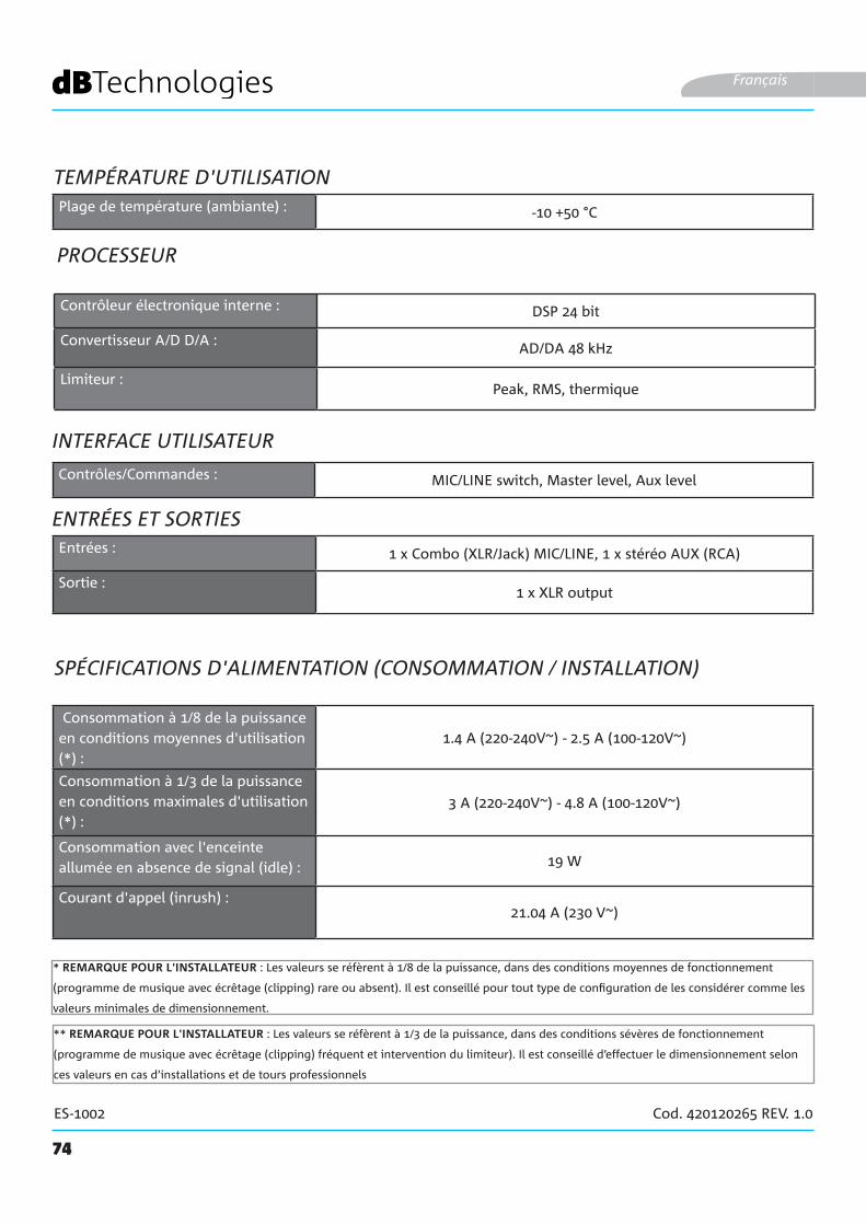
74
ES-1002 Cod. 420120265 REV. 1.0
PROCESSEUR
ENTRÉES ET SORTIES
Français
INTERFACE UTILISATEUR
Consommation à 1/8 de la puissance en conditions moyennes d'utilisation (*) :
1.4 A (220-240V~) - 2.5 A (100-120V~)
Consommation à 1/3 de la puissance en conditions maximales d'utilisation (*) :
3 A (220-240V~) - 4.8 A (100-120V~)
Consommation avec l'enceinte allumée en absence de signal (idle) : 19 W
Courant d'appel (inrush) :21.04 A (230 V~)
SPÉCIFICATIONS D'ALIMENTATION (CONSOMMATION / INSTALLATION)
* REMARQUE POUR L'INSTALLATEUR : Les valeurs se réfèrent à 1/8 de la puissance, dans des conditions moyennes de fonctionnement
(programme de musique avec écrêtage (clipping) rare ou absent). Il est conseillé pour tout type de configuration de les considérer comme les
valeurs minimales de dimensionnement.
** REMARQUE POUR L'INSTALLATEUR : Les valeurs se réfèrent à 1/3 de la puissance, dans des conditions sévères de fonctionnement
(programme de musique avec écrêtage (clipping) fréquent et intervention du limiteur). Il est conseillé d’effectuer le dimensionnement selon
ces valeurs en cas d’installations et de tours professionnels
Contrôleur électronique interne : DSP 24 bit
Convertisseur A/D D/A : AD/DA 48 kHz
Limiteur :Peak, RMS, thermique
Contrôles/Commandes : MIC/LINE switch, Master level, Aux level
Entrées : 1 x Combo (XLR/Jack) MIC/LINE, 1 x stéréo AUX (RCA)
Sortie :1 x XLR output
TEMPÉRATURE D'UTILISATIONPlage de température (ambiante) : -10 +50 °C
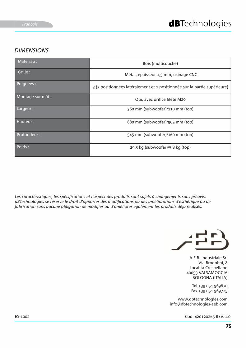
75
ES-1002 Cod. 420120265 REV. 1.0
DIMENSIONS
Les caractéristiques, les spécifications et l'aspect des produits sont sujets à changements sans préavis. dBTechnologies se réserve le droit d'apporter des modifications ou des améliorations d'esthétique ou de fabrication sans aucune obligation de modifier ou d'améliorer également les produits déjà réalisés.
A.E.B. Industriale SrlVia Brodolini, 8
Località Crespellano40053 VALSAMOGGIA
BOLOGNA (ITALIA)
Tel +39 051 969870Fax +39 051 969725
Français
Matériau : Bois (multicouche)
Grille : Métal, épaisseur 1,5 mm, usinage CNC
Poignées :3 (2 positionnées latéralement et 1 positionnée sur la partie supérieure)
Montage sur mât :Oui, avec orifice fileté M20
Largeur : 360 mm (subwoofer)/110 mm (top)
Hauteur : 680 mm (subwoofer)/905 mm (top)
Profondeur : 545 mm (subwoofer)/160 mm (top)
Poids : 29,3 kg (subwoofer)/5.8 kg (top)

76
ES-1002 Cód. 420120265 REV. 1.0
ÍNDICE
1. INFORMACIÓN GENERAL .................................................................................................... 78¡ENHORABUENA! ............................................................................................................. 78INTRODUCCIÓN ................................................................................................................ 78CONTENIDO DE LOS EMBALAJES .................................................................................... 78NOTAS PARA EL USUARIO ................................................................................................ 78CARACTERÍSTICAS MECÁNICAS Y ACÚSTICAS ................................................................ 79
DIMENSIONES .......................................................................................................................................... 79COBERTURA ACÚSTICA ........................................................................................................................... 79MONTAJE DEL PIE TELESCÓPICO (SUMINISTRADO) EN EL SUBWOOFER ............................................ 80TERMINACIÓN DEL SISTEMA ................................................................................................................... 80
CARACTERÍSTICAS DE LA SECCIÓN DE AMPLIFICACIÓN Y CONTROL ........................... 81SECCIÓN DE ENTRADA, SALIDA Y CONTROL ......................................................................................... 81AMPLIFICADOR ........................................................................................................................................ 81SECCIÓN DE ALIMENTACIÓN Y CONEXIÓN DE LAS CAJAS ACÚSTICAS ................................................ 81SECCIÓN DE ENTRADA, SALIDA Y CONTROL ......................................................................................... 82SECCIÓN DE ALIMENTACIÓN Y CONEXIÓN DE LAS CAJAS ACÚSTICAS ................................................ 83
2. CONFIGURACIONES DE USO ............................................................................................ 84CONFIGURACIONES EN EL SUELO ................................................................................ 84INSTALACIÓN FIJA EN LA PARED .................................................................................. 84
3. PRIMER ENCENDIDO ........................................................................................................... 85CONEXIÓN DE LA CAJA ACÚSTICA AL SUBWOOFER ............................................................................. 85CONEXIÓN DE LAS ENTRADAS ................................................................................................................ 86CONEXIÓN DE LA SALIDA DEL SISTEMA ................................................................................................ 87CONEXIÓN DE LA ALIMENTACIÓN.......................................................................................................... 88
4. ACCESORIOS ......................................................................................................................... 895. SOLUCIÓN DE PROBLEMAS ................................................................................................ 906. CARACTERÍSTICAS TÉCNICAS ............................................................................................. 91
GENERALES .............................................................................................................................................. 91DATOS ACÚSTICOS ................................................................................................................................... 91AMPLIFICADOR ........................................................................................................................................ 91TEMPERATURA DE USO ........................................................................................................................... 92PROCESADOR........................................................................................................................................... 92INTERFAZ DE USUARIO ............................................................................................................................ 92ENTRADAS Y SALIDAS ............................................................................................................................. 92CARACTERÍSTICAS DE LA ALIMENTACIÓN (ABSORCIÓN / INSTALACIÓN) ............................................. 92DIMENSIONES .......................................................................................................................................... 93
77
ES-1002 Cód. 420120265 REV. 1.0
ÍNDICE
Español
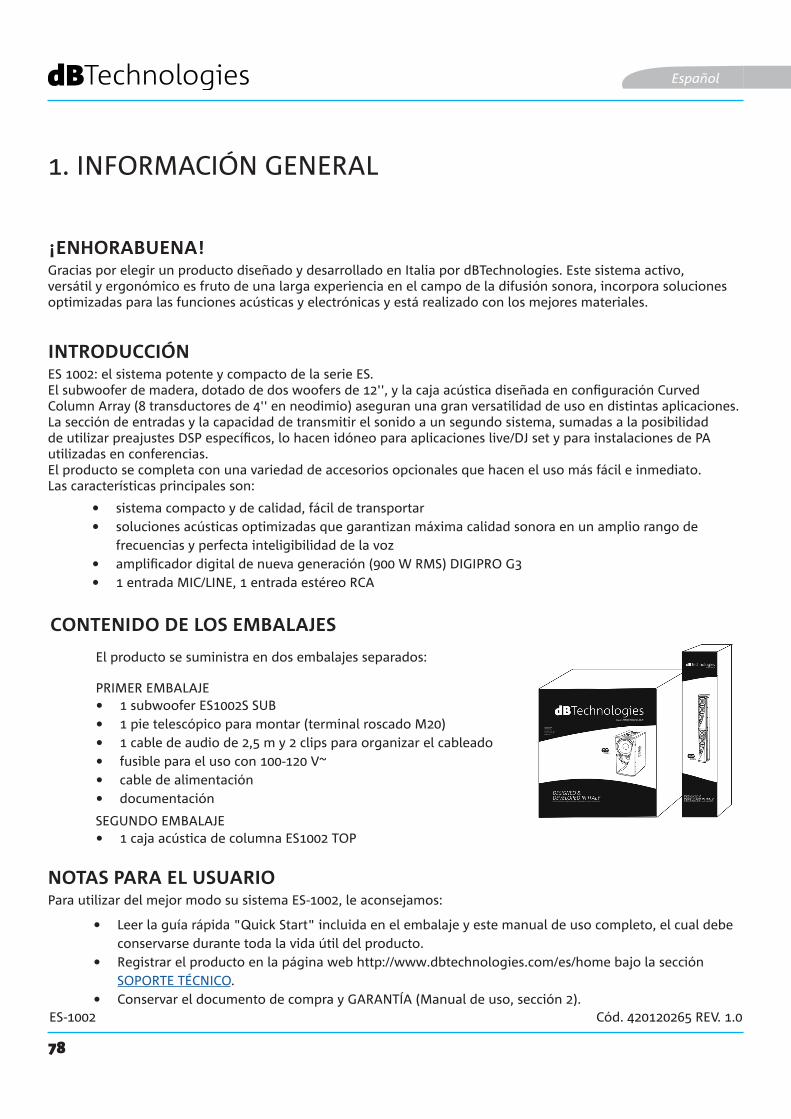
78
ES-1002 Cód. 420120265 REV. 1.0
1. INFORMACIÓN GENERAL
¡ENHORABUENA!
INTRODUCCIÓN
NOTAS PARA EL USUARIO
Gracias por elegir un producto diseñado y desarrollado en Italia por dBTechnologies. Este sistema activo, versátil y ergonómico es fruto de una larga experiencia en el campo de la difusión sonora, incorpora soluciones optimizadas para las funciones acústicas y electrónicas y está realizado con los mejores materiales.
ES 1002: el sistema potente y compacto de la serie ES.El subwoofer de madera, dotado de dos woofers de 12'', y la caja acústica diseñada en configuración Curved Column Array (8 transductores de 4'' en neodimio) aseguran una gran versatilidad de uso en distintas aplicaciones.La sección de entradas y la capacidad de transmitir el sonido a un segundo sistema, sumadas a la posibilidad de utilizar preajustes DSP específicos, lo hacen idóneo para aplicaciones live/DJ set y para instalaciones de PA utilizadas en conferencias.El producto se completa con una variedad de accesorios opcionales que hacen el uso más fácil e inmediato. Las características principales son:
Para utilizar del mejor modo su sistema ES-1002, le aconsejamos:
• sistema compacto y de calidad, fácil de transportar• soluciones acústicas optimizadas que garantizan máxima calidad sonora en un amplio rango de
frecuencias y perfecta inteligibilidad de la voz • amplificador digital de nueva generación (900 W RMS) DIGIPRO G3• 1 entrada MIC/LINE, 1 entrada estéreo RCA
• Leer la guía rápida "Quick Start" incluida en el embalaje y este manual de uso completo, el cual debe conservarse durante toda la vida útil del producto.
• Registrar el producto en la página web http://www.dbtechnologies.com/es/home bajo la sección SOPORTE TÉCNICO.
• Conservar el documento de compra y GARANTÍA (Manual de uso, sección 2).
Español
CONTENIDO DE LOS EMBALAJES
• 1 subwoofer ES1002S SUB• 1 pie telescópico para montar (terminal roscado M20)• 1 cable de audio de 2,5 m y 2 clips para organizar el cableado• fusible para el uso con 100-120 V~• cable de alimentación• documentación
El producto se suministra en dos embalajes separados:
PRIMER EMBALAJE
SEGUNDO EMBALAJE• 1 caja acústica de columna ES1002 TOP
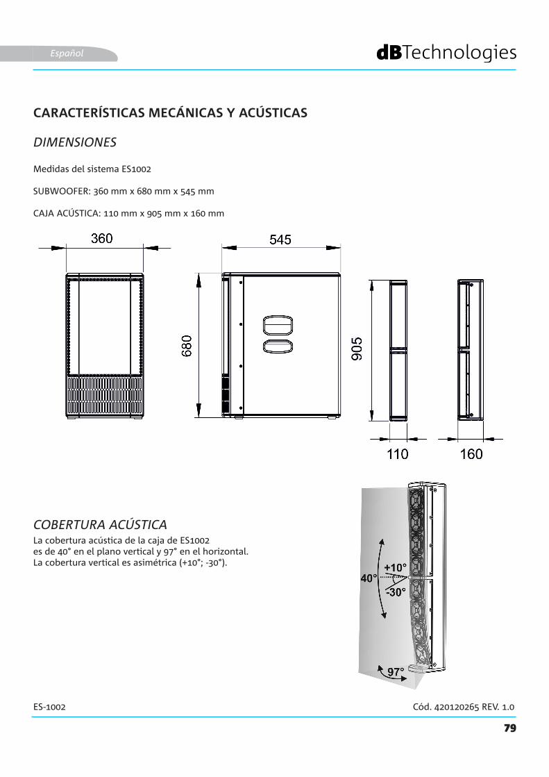
79
ES-1002 Cód. 420120265 REV. 1.0
CARACTERÍSTICAS MECÁNICAS Y ACÚSTICAS
DIMENSIONES
COBERTURA ACÚSTICA
Medidas del sistema ES1002
SUBWOOFER: 360 mm x 680 mm x 545 mm
CAJA ACÚSTICA: 110 mm x 905 mm x 160 mm
La cobertura acústica de la caja de ES1002es de 40° en el plano vertical y 97° en el horizontal. La cobertura vertical es asimétrica (+10°; -30°).
Español

80
ES-1002 Cód. 420120265 REV. 1.0
MONTAJE DEL PIE TELESCÓPICO (SUMINISTRADO) EN EL SUBWOOFER
El subwoofer (ES1002 SUB) está dotado de tres asas de transporte [Y]: dos laterales y una superior. En la parte superior hay un orificio con rosca M20 [Z] para aplicar el pie telescópico suministrado de serie.Para montar el pie telescópico:• Enrosque hacia la derecha la parte superior telescópica en la parte inferior fija.• Enrosque hacia la derecha el pie ya ensamblado en el orificio [Z].El pie de altura regulable se introduce en el orificio [X] de la caja acústica. Para más información, incluidas las alturas máximas de instalación permitidas, consulte el capítulo 2. CONFIGURACIONES DE USO.
Español
TERMINACIÓN DEL SISTEMA
La caja acústica (ES1002 TOP) tiene en la parte inferior un orificio de 36 mm de diámetro [A] y una conexión [B] para el cable con conector speakON incluido.• Inserte el conector speakON como se ilustra en la figura.• Coloque la caja acústica sobre el pie anteriormente enroscado.Para más información sobre el cableado, consulte el capítulo 3. PRIMER ENCENDIDO.
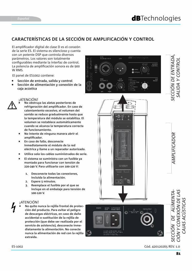
81
ES-1002 Cód. 420120265 REV. 1.0
CARACTERÍSTICAS DE LA SECCIÓN DE AMPLIFICACIÓN Y CONTROL
El amplificador digital de clase D es el corazón de la serie ES. El sistema es silencioso y cuenta con un potente DSP que controla diversos parámetros. Los valores son totalmente configurables mediante la interfaz de control.La potencia de amplificación sonora es de 900 W RMS.
El panel de ES1002 contiene:
¡ATENCIÓN!
• Sección de entrada, salida y control• Sección de alimentación y conexión de la
caja acústica
Español
• No obstruya las aletas posteriores de refrigeración del amplificador. En caso de calentamiento excesivo, el volumen del sonido se reduce gradualmente hasta que la temperatura del módulo se estabiliza. El volumen se restablece automáticamente cuando se alcanza la temperatura correcta de funcionamiento.
• No intente de ninguna manera abrir el amplificador.
• En caso de fallo, desconecte inmediatamente el módulo de la red eléctrica y llame a un reparador autorizado.
• El sistema se suministra con un fusible ya montado para funcionar con tensión de 220-240 V. Para utilizarlo con 100-120 V:
1. Desconecte todas las conexiones, incluida la alimentación.
2. Espere 5 minutos.3. Reemplace el fusible por el que se
incluye en el embalaje para tensión de 100-120 V.
• Utilice solo los cables suministrados de serie.
• No quite nunca la rejilla frontal de protec-ción del producto. Para evitar el peligro de descargas eléctricas, en caso de daño accidental o sustitución de la rejilla de protección (que debe ser realizada por el servicio de asistencia), desconecte inme-diatamente la alimentación. No conecte nunca la alimentación de red con la rejilla extraída.
¡ATENCIÓN!
SEC
CIÓ
N D
E EN
TRA
DA
, SA
LID
A Y
CO
NTR
OL
AM
PLIF
ICA
DO
RSE
CC
IÓN
D
E A
LIM
ENTA
-C
IÓN
Y C
ON
EXIÓ
N D
E LA
S C
AJA
S A
CÚ
STIC
AS
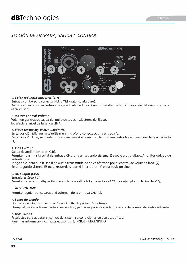
82
ES-1002 Cód. 420120265 REV. 1.0
SECCIÓN DE ENTRADA, SALIDA Y CONTROL
1. Balanced Input MIC/LINE (CH1) Entrada combo para conector XLR o TRS (balanceada o no). Permite conectar un micrófono o una entrada de línea. Para los detalles de la configuración del canal, consulte el capítulo 3.
Español
2. Master Control VolumeVolumen general de salida de audio de los transductores de ES1002.No afecta el nivel de la salida LINK.
5. AUX Input (CH2) Entrada estéreo RCA.Permite conectar un dispositivo de audio con salida L-R y conectores RCA; por ejemplo, un lector de MP3.
3. Input sensitivity switch (Line/Mic) En la posición Mic, permite utilizar un micrófono conectado a la entrada [1].En la posición Line, se puede utilizar una conexión a un mezclador o una entrada de línea conectada al conector [1].
4. Link OutputSalida de audio (conector XLR).Permite transmitir la señal de entrada CH1 [1] a un segundo sistema ES1002 o a otro altavoz/monitor dotado de entrada Line. Tenga en cuenta que la señal de audio transmitida no se ve afectada por el control de volumen local [2].En el segundo sistema ES1002, recuerde situar el interruptor [3] en la posición Line.
6. AUX VOLUMEPermite regular por separado el volumen de la entrada CH2 [5].
7. Ledes de estadoLimiter: se enciende cuando actúa el circuito de protección interna.On-signal: destella brevemente al encendido; parpadea para indicar la presencia de la señal de audio entrante.
8. DSP PRESET Preajustes para adaptar el sonido del sistema a condiciones de uso específicas.Para más información, consulte el capítulo 3. PRIMER ENCENDIDO.
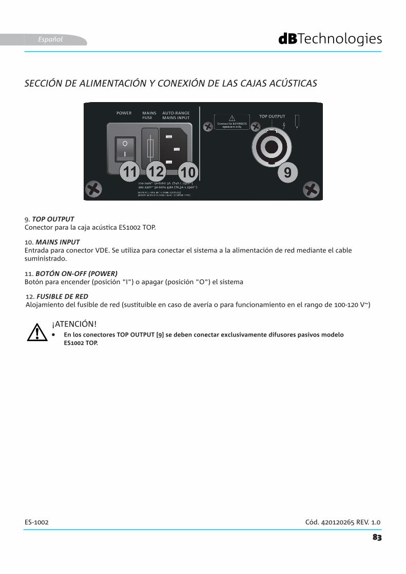
83
ES-1002 Cód. 420120265 REV. 1.0
10. MAINS INPUTEntrada para conector VDE. Se utiliza para conectar el sistema a la alimentación de red mediante el cable suministrado.
9. TOP OUTPUTConector para la caja acústica ES1002 TOP.
SECCIÓN DE ALIMENTACIÓN Y CONEXIÓN DE LAS CAJAS ACÚSTICAS
Español
11. BOTÓN ON-OFF (POWER)Botón para encender (posición "I") o apagar (posición "O") el sistema
12. FUSIBLE DE REDAlojamiento del fusible de red (sustituible en caso de avería o para funcionamiento en el rango de 100-120 V~)
¡ATENCIÓN!• En los conectores TOP OUTPUT [9] se deben conectar exclusivamente difusores pasivos modelo
ES1002 TOP.
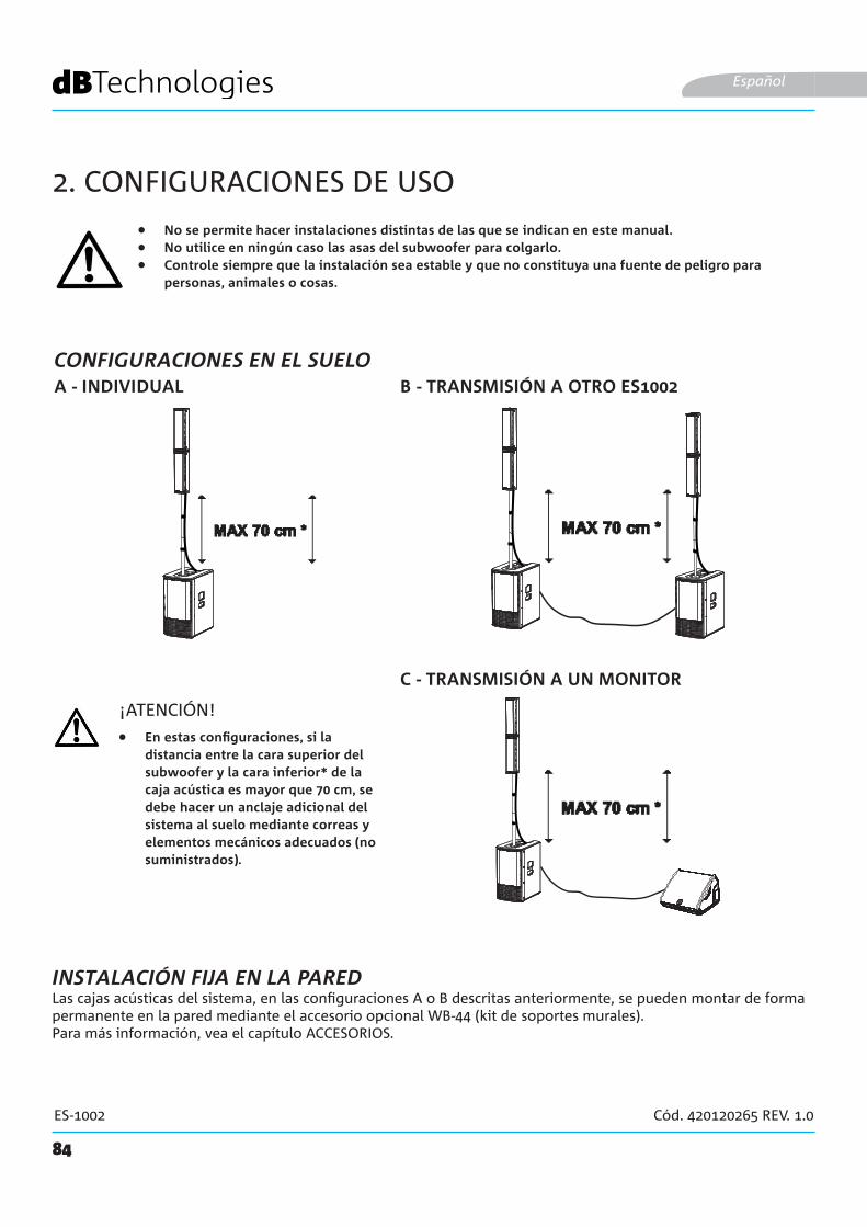
84
ES-1002 Cód. 420120265 REV. 1.0
2. CONFIGURACIONES DE USO
• No se permite hacer instalaciones distintas de las que se indican en este manual.• No utilice en ningún caso las asas del subwoofer para colgarlo.• Controle siempre que la instalación sea estable y que no constituya una fuente de peligro para
personas, animales o cosas.
B - TRANSMISIÓN A OTRO ES1002A - INDIVIDUAL
Español
¡ATENCIÓN!
Las cajas acústicas del sistema, en las configuraciones A o B descritas anteriormente, se pueden montar de forma permanente en la pared mediante el accesorio opcional WB-44 (kit de soportes murales).Para más información, vea el capítulo ACCESORIOS.
INSTALACIÓN FIJA EN LA PARED
• En estas configuraciones, si la distancia entre la cara superior del subwoofer y la cara inferior* de la caja acústica es mayor que 70 cm, se debe hacer un anclaje adicional del sistema al suelo mediante correas y elementos mecánicos adecuados (no suministrados).
C - TRANSMISIÓN A UN MONITOR
CONFIGURACIONES EN EL SUELO
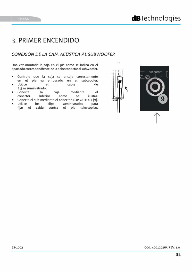
85
ES-1002 Cód. 420120265 REV. 1.0
3. PRIMER ENCENDIDO
CONEXIÓN DE LA CAJA ACÚSTICA AL SUBWOOFER
Español
Una vez montada la caja en el pie como se indica en el apartado correspondiente, se la debe conectar al subwoofer.
• Controle que la caja se encaje correctamente en el pie ya enroscado en el subwoofer.
• Utilice el cable de 2,5 m suministrado.• Conecte la caja mediante el
conector inferior como se ilustra.• Conecte el sub mediante el conector TOP OUTPUT [9]. • Utilice los clips suministrados para
fijar el cable contra el pie telescópico.

RL
RL
STEREO INPUT
86
ES-1002 Cód. 420120265 REV. 1.0
CONEXIÓN DE LAS ENTRADAS
Español
• Conecte un micrófono al conector [1].
• Ajuste el tipo de entrada (MIC) en el selector [3].
• Conecte una fuente estéreo (por ejemplo, un lector de MP3) a la entrada estéreo RCA [5].
• Regule los volúmenes [6] y [2] .
MIC
STEREO INPUT
PRIMER EJEMPLO
LINE
SEGUNDO EJEMPLO
• Conecte un mezclador al conector [1].
• Ajuste el tipo de entrada (LINE) en el selector [3].
• Conecte una fuente estéreo (por ejemplo, un lector de CD) a la entrada estéreo RCA [5].
• Regule los volúmenes [6] y [2] .

87
ES-1002 Cód. 420120265 REV. 1.0
MONITORES 1002
Español
CONEXIÓN DE LA SALIDA DEL SISTEMA
Para transmitir el sonido a otro sistema ES1002:
• Conecte el conector de salida [4] del primer ES1002 a la entrada CH1 del segundo sistema.
• Ajuste el tipo de entrada (LINE) en el selector [3] del segundo sistema.
PRIMER SISTEMA SEGUNDO SISTEMA
CONFIGURACIÓN CON TRANSMISIÓN A OTRO SISTEMA
TRANSMISIÓN DE LA SALIDA A UN MONITOR
XLR
XLR
Para transmitir el sonido a un monitor:
• Conecte el conector de salida [4] de ES1002 a la entrada de un monitor.
• Si el monitor está provisto de selector, ajuste el tipo de entrada (LINE) en él.
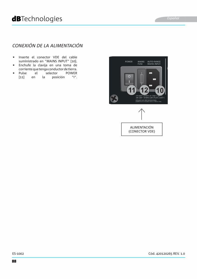
88
ES-1002 Cód. 420120265 REV. 1.0
CONEXIÓN DE LA ALIMENTACIÓN
Español
ALIMENTACIÓN(CONECTOR VDE)
• Inserte el conector VDE del cable suministrado en "MAINS INPUT" [10].
• Enchufe la clavija en una toma de corriente que tenga conductor de tierra.
• Pulse el selector POWER [11] en la posición "I".
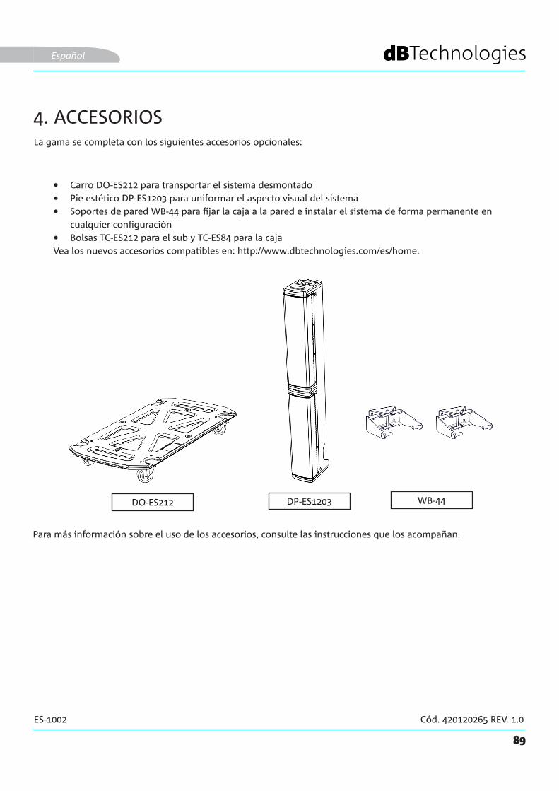
DP-ES1203DO-ES212
89
ES-1002 Cód. 420120265 REV. 1.0
WB-44
La gama se completa con los siguientes accesorios opcionales:
• Carro DO-ES212 para transportar el sistema desmontado• Pie estético DP-ES1203 para uniformar el aspecto visual del sistema • Soportes de pared WB-44 para fijar la caja a la pared e instalar el sistema de forma permanente en
cualquier configuración• Bolsas TC-ES212 para el sub y TC-ES84 para la cajaVea los nuevos accesorios compatibles en: http://www.dbtechnologies.com/es/home.
Español
4. ACCESORIOS
Para más información sobre el uso de los accesorios, consulte las instrucciones que los acompañan.
90
ES-1002 Cód. 420120265 REV. 1.0
5. SOLUCIÓN DE PROBLEMAS
1. Compruebe que el sistema reciba alimentación eléctrica.2. Controle que el cable de alimentación con conector VDE esté bien insertado y el selector de encendido
se encuentre en la posición ON.
1. Controle que la conexión de entrada de la señal de audio se haya realizado correctamente.2. Controle que los cables no estén dañados.3. Controle las conexiones entre la caja y el subwoofer.4. Controle que el mezclador o la fuente de audio se haya encendido y muestre claramente la presencia de
la señal de salida.5. Controle que la configuración de los niveles de entrada y del tipo de entrada y de salida sea correcta.
1. Controle que los cables no estén dañados y, si lo están, proceda a sustituirlos: un cable dañado puede hacer que la señal se pierda o se altere.
2. Controle que la configuración de los niveles de entrada y del tipo de entrada y de salida sea correcta.
El sistema no se enciende
El difusor se enciende pero no emite ningún sonido:
El difusor emite un sonido insuficiente o distorsionado:
Español
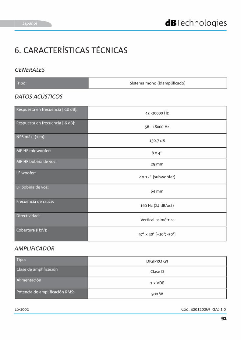
91
ES-1002 Cód. 420120265 REV. 1.0
6. CARACTERÍSTICAS TÉCNICAS
GENERALES
DATOS ACÚSTICOS
AMPLIFICADOR
Tipo: Sistema mono (biamplificado)
Español
Respuesta en frecuencia [-10 dB]: 43 -20000 Hz
Respuesta en frecuencia [-6 dB]: 56 - 18000 Hz
NPS máx. (1 m):130,7 dB
MF-HF midwoofer: 8 x 4''
MF-HF bobina de voz:25 mm
LF woofer:2 x 12" (subwoofer)
LF bobina de voz:64 mm
Frecuencia de cruce:160 Hz (24 dB/oct)
Directividad: Vertical asimétrica
Cobertura (HxV):97° x 40° [+10°; -30°]
Tipo: DIGIPRO G3
Clase de amplificación Clase D
Alimentación1 x VDE
Potencia de amplificación RMS: 900 W
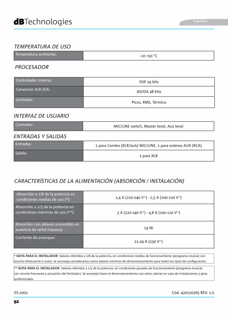
92
ES-1002 Cód. 420120265 REV. 1.0
PROCESADOR
ENTRADAS Y SALIDAS
Español
INTERFAZ DE USUARIO
Absorción a 1/8 de la potencia en condiciones medias de uso (*): 1,4 A (220-240 V~) - 2,5 A (100-120 V~)
Absorción a 1/3 de la potencia en condiciones máximas de uso (**): 3 A (220-240 V~) - 4,8 A (100-120 V~)
Absorción con altavoz encendido en ausencia de señal (reposo): 19 W
Corriente de arranque:21,04 A (230 V~)
CARACTERÍSTICAS DE LA ALIMENTACIÓN (ABSORCIÓN / INSTALACIÓN)
* NOTA PARA EL INSTALADOR: Valores referidos a 1/8 de la potencia, en condiciones medias de funcionamiento (programa musical con
recorte infrecuente o nulo). Se aconseja considerarlos como valores mínimos de dimensionamiento para todos los tipos de configuración.
** NOTA PARA EL INSTALADOR: Valores referidos a 1/3 de la potencia, en condiciones pesadas de funcionamiento (programa musical
con recorte frecuente y actuación del limitador). Se aconseja hacer el dimensionamiento con estos valores en caso de instalaciones y giras
profesionales.
Controlador interno: DSP 24 bits
Conversor A/D D/A: AD/DA 48 kHz
Limitador:Picos, RMS, Térmico
Controles: MIC/LINE switch, Master level, Aux level
Entradas: 1 para Combo (XLR/Jack) MIC/LINE, 1 para estéreo AUX (RCA)
Salida:1 para XLR
TEMPERATURA DE USOTemperatura ambiente: -10 +50 °C

93
ES-1002 Cód. 420120265 REV. 1.0
DIMENSIONES
Las características y el aspecto de los productos pueden cambiar sin previo aviso. dBTechnologies se reserva el derecho a hacer modificaciones o mejoras en el diseño o en la fabricación sin obligación de cambiar o mejorar los productos realizados anteriormente.
A.E.B. Industriale SrlVia Brodolini, 8
Località Crespellano40053 VALSAMOGGIA
BOLONIA (ITALIA)
Tel. +39 051 969870Fax +39 051 969725
Español
Material: Madera multicapa
Rejilla: Metal, espesor 1,5 mm, mecanizado con CNC
Asas:3 (2 laterales y 1 superior)
Montaje sobre pie:Sí, con orificio roscado M20
Anchura: 360 mm (subwoofer) / 110 mm (caja)
Altura: 680 mm (subwoofer) / 905 mm (caja)
Fondo: 545 mm (subwoofer) / 160 mm (caja)
Peso: 29,3 kg (subwoofer) / 5,8 kg (caja)


![Security Grade 2 Grado di sicurezza 2 Environmental Class ... · 7 IMP. INGRESSI? Ingresso [01] Ingr. 01 RESISTENZE EOL? x t x Scegli Tipo [00] Non Usato Ingresso in Area [A] Ingresso](https://img.pdfslide.us/doc/110x75/5ac1fb277f8b9a213f8db539/security-grade-2-grado-di-sicurezza-2-environmental-class-imp-ingressi-ingresso.jpg)