Embed Size (px)
DESCRIPTION
dsa
Citation preview
Fieldbus
For central control
Contents
Why use Fieldbus A comparison Where to use Fieldbus Fieldbus types Serial communication Topology Nodes and I/O Communication Gateways Protocol
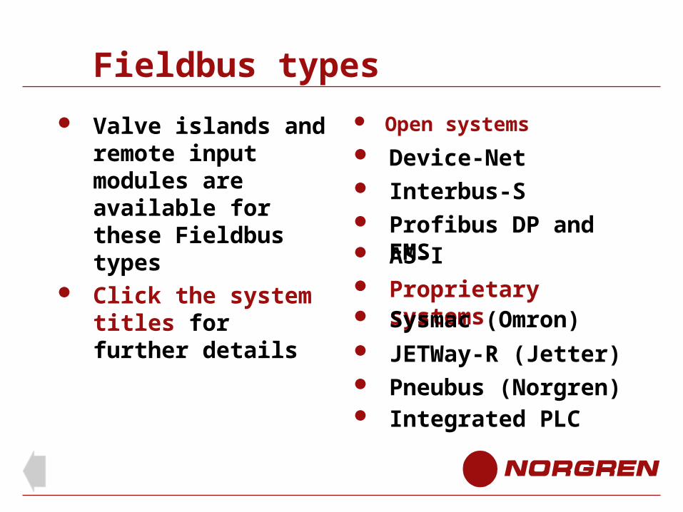
Valve Islands Remote input modules Fieldbus types
DeviceNet Interbus Profibus AS-I JETWay-R Sysmac Integrated PLC
Programming
Click the section to advance directly to it
Introduction
Messages
Introduction
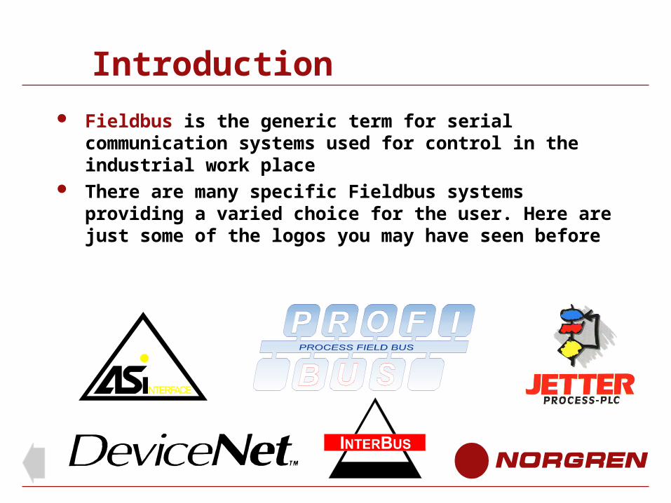
Fieldbus is the generic term for serial communication systems used for control in the industrial work place
There are many specific Fieldbus systems providing a varied choice for the user. Here are just some of the logos you may have seen before
Introduction
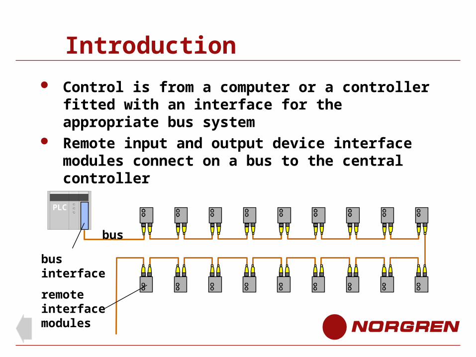
Control is from a computer or a controller fitted with an interface for the appropriate bus system
Remote input and output device interface modules connect on a bus to the central controller
bus
PLC
bus interface
remote interfacemodules
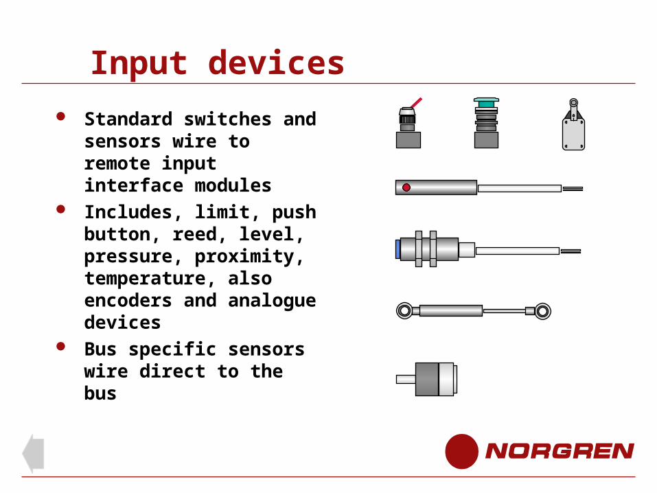
Input devices
Standard switches and sensors wire to remote input interface modules
Includes, limit, push button, reed, level, pressure, proximity, temperature, also encoders and analogue devices
Bus specific sensors wire direct to the bus
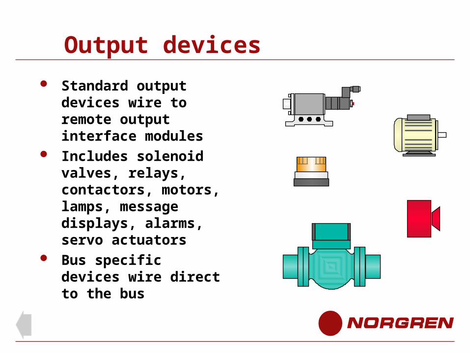
Output devices
Standard output devices wire to remote output interface modules
Includes solenoid valves, relays, contactors, motors, lamps, message displays, alarms, servo actuators
Bus specific devices wire direct to the bus
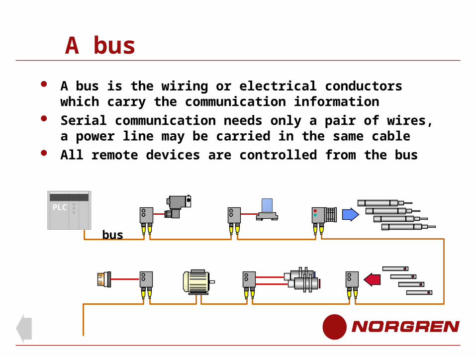
A bus
A bus is the wiring or electrical conductors which carry the communication information
Serial communication needs only a pair of wires, a power line may be carried in the same cable
All remote devices are controlled from the bus
bus
PLC
Why use Fieldbus
For centralised control of remote input and output devices
To reduce the quantity of wiring To simplify cable routing Cost reduction Centralised diagnostics and monitoring
Benefits
Reduced cabling Reduced controller hardware ( requires no I/O ) Reduced assembly and installation time Reduced costs Better diagnostics Reduced machine downtime Increased productivity Simply made additions and modifications Increased flexibility
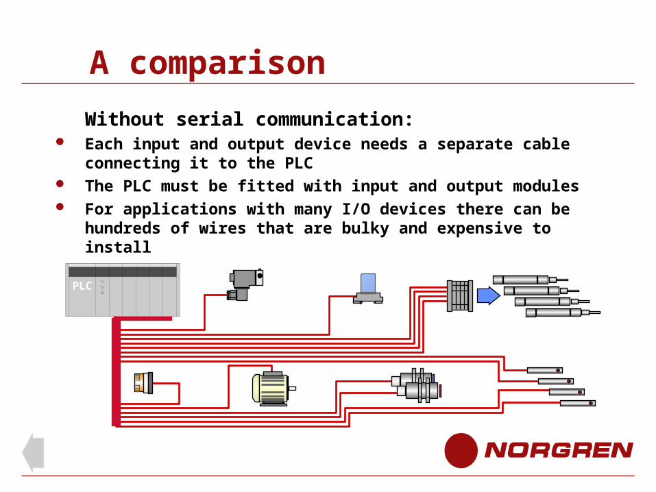
A comparison
Without serial communication: Each input and output device needs a separate cable
connecting it to the PLC The PLC must be fitted with input and output modules For applications with many I/O devices there can be
hundreds of wires that are bulky and expensive to install
plc
PLC
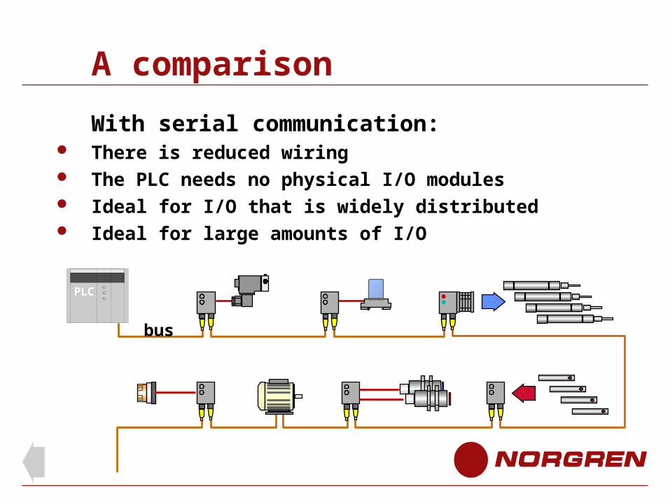
A comparison
With serial communication: There is reduced wiring The PLC needs no physical I/O modules Ideal for I/O that is widely distributed Ideal for large amounts of I/O
bus
PLC
Where to use Fieldbus
Machines with widely distributed I/O (input output) devices
Integrated process control
Assembly plant Manufacturing plant
consisting of many different machines
Monitoring and data collection systems
Applications include: Automotive assembly Paper making Printing Airport goods handling Chemical processing Food and drink packaging Energy production Security systems Water treatment Traffic control
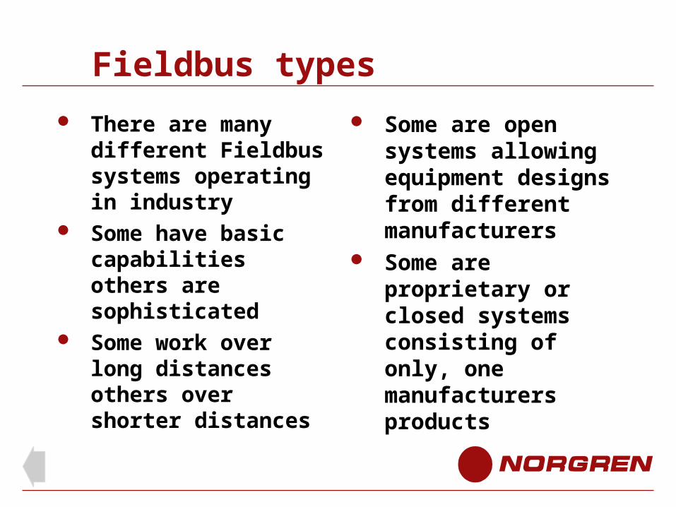
Fieldbus types
There are many different Fieldbus systems operating in industry
Some have basic capabilities others are sophisticated
Some work over long distances others over shorter distances
Some are open systems allowing equipment designs from different manufacturers
Some are proprietary or closed systems consisting of only, one manufacturers products
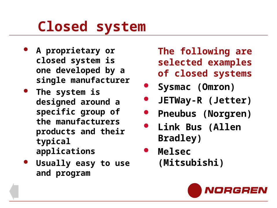
Closed system
A proprietary or closed system is one developed by a single manufacturer
The system is designed around a specific group of the manufacturers products and their typical applications
Usually easy to use and program
The following are selected examples of closed systems
Sysmac (Omron) JETWay-R (Jetter) Pneubus (Norgren) Link Bus (Allen
Bradley) Melsec (Mitsubishi)
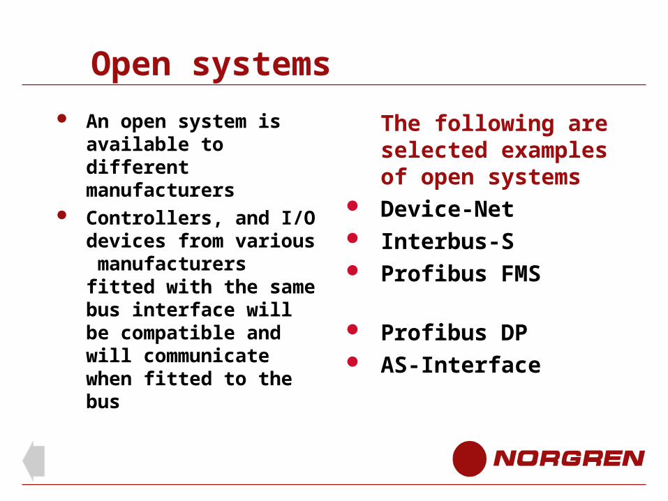
Open systems
An open system is available to different manufacturers
Controllers, and I/O devices from various manufacturers fitted with the same bus interface will be compatible and will communicate when fitted to the bus
The following are selected examples of open systems
Device-Net Interbus-S Profibus FMS Profibus DP AS-Interface
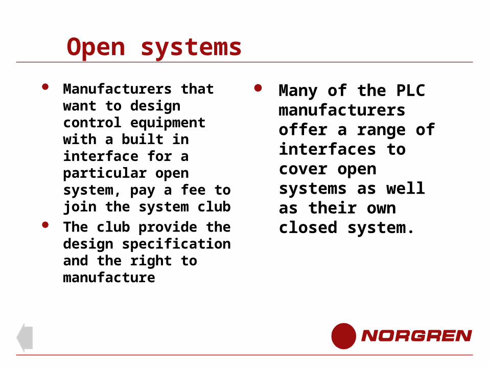
Open systems
Manufacturers that want to design control equipment with a built in interface for a particular open system, pay a fee to join the system club
The club provide the design specification and the right to manufacture
Many of the PLC manufacturers offer a range of interfaces to cover open systems as well as their own closed system.
Serial communication
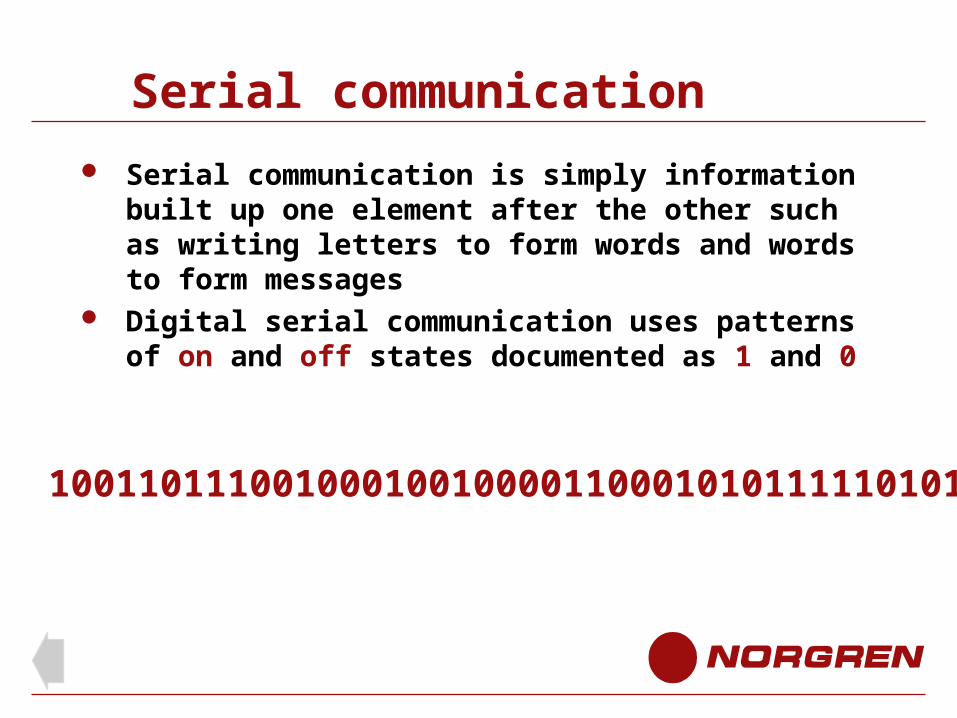
Serial communication is simply information built up one element after the other such as writing letters to form words and words to form messages
Digital serial communication uses patterns of on and off states documented as 1 and 0
10011011100100010010000110001010111110101
Serial communication
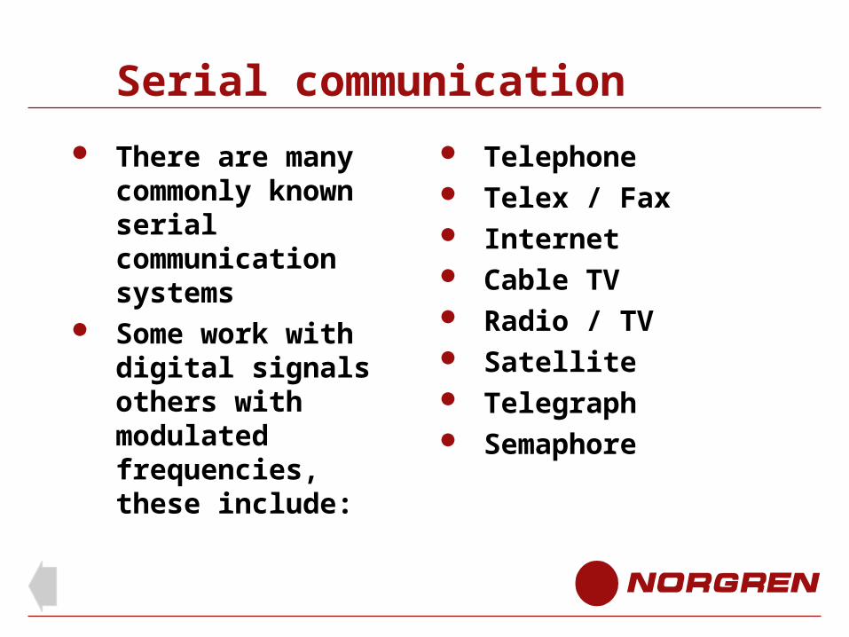
There are many commonly known serial communication systems
Some work with digital signals others with modulated frequencies, these include:
Telephone Telex / Fax Internet Cable TV Radio / TV Satellite Telegraph Semaphore
Topology
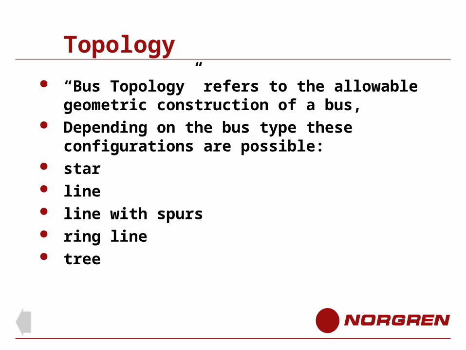
“Bus Topology” refers to the allowable geometric construction of a bus,
Depending on the bus type these configurations are possible:
star line line with spurs ring line tree
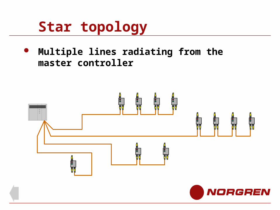
Star topology
Multiple lines radiating from the master controller
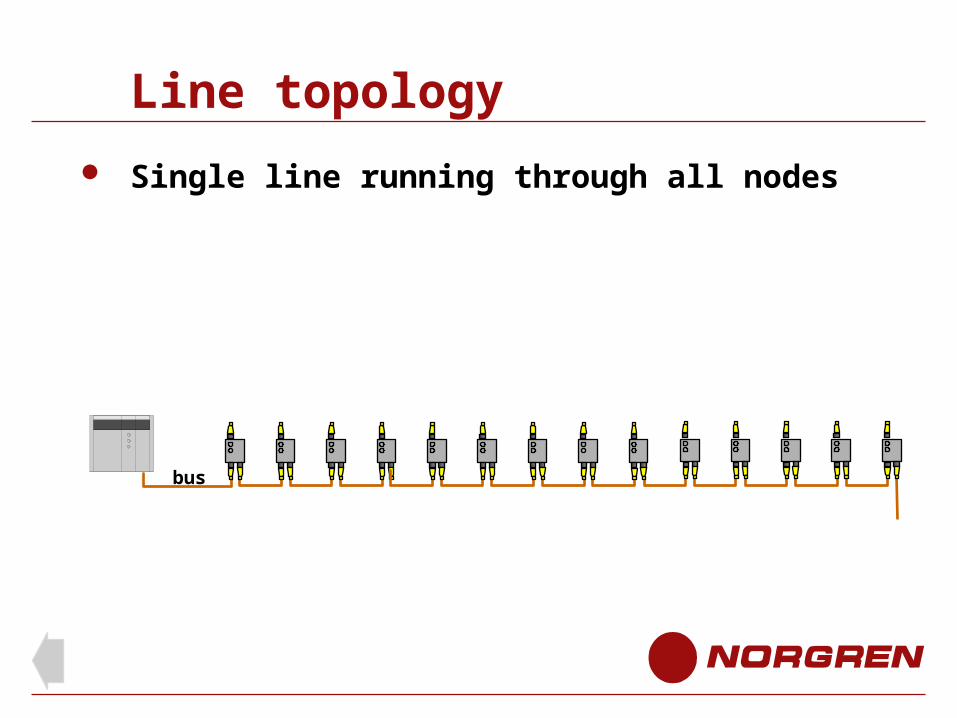
Line topology
Single line running through all nodes
bus
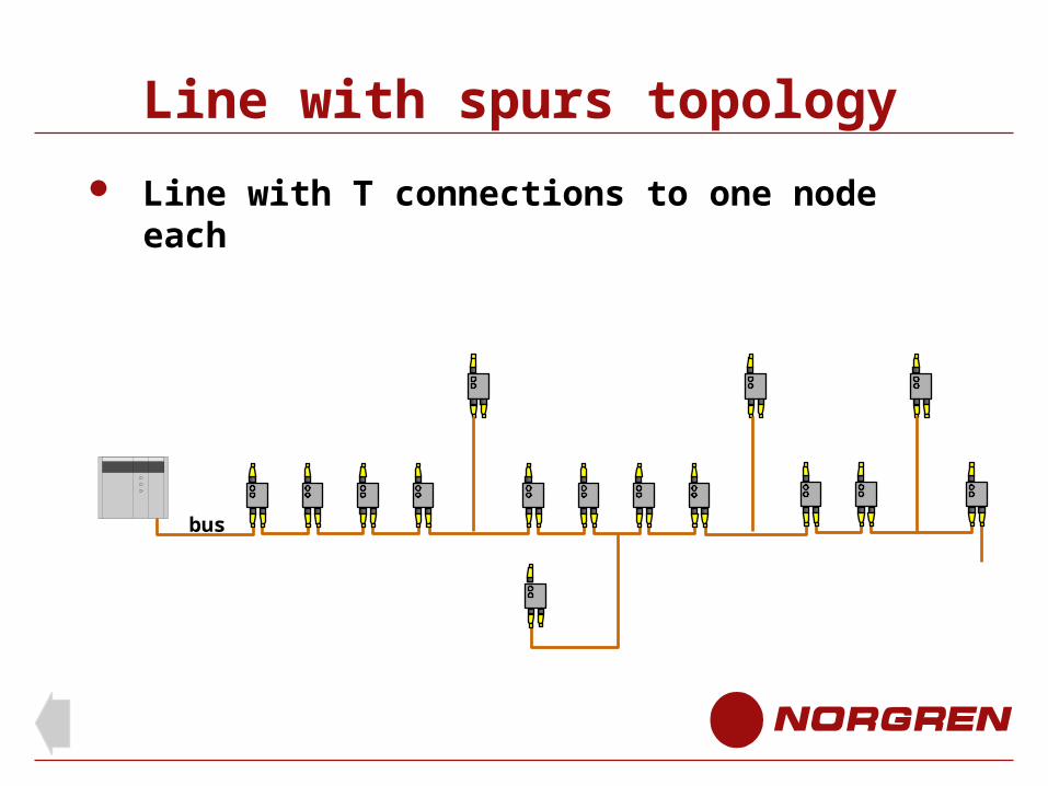
Line with spurs topology
Line with T connections to one node each
bus
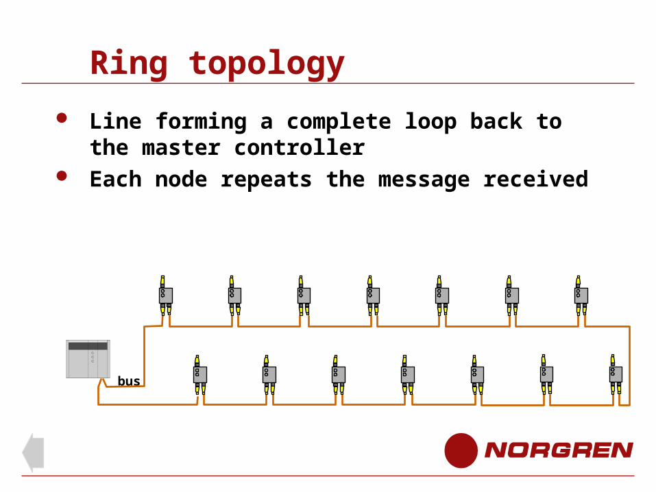
Ring topology
Line forming a complete loop back to the master controller
Each node repeats the message received
bus
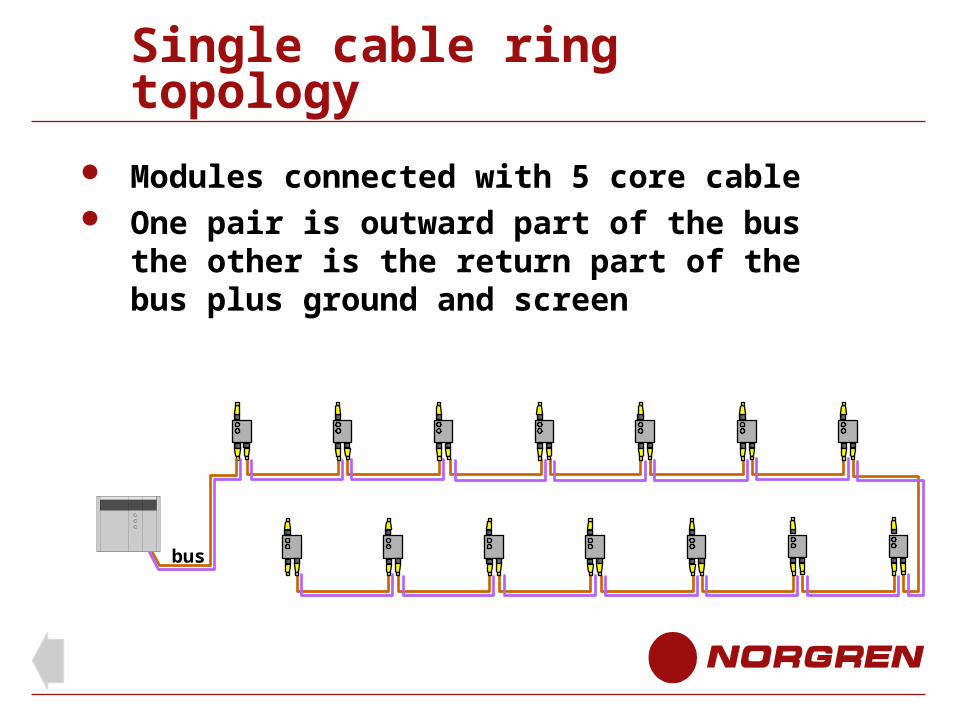
Single cable ring topology
Modules connected with 5 core cable One pair is outward part of the bus the other is
the return part of the bus plus ground and screen
bus
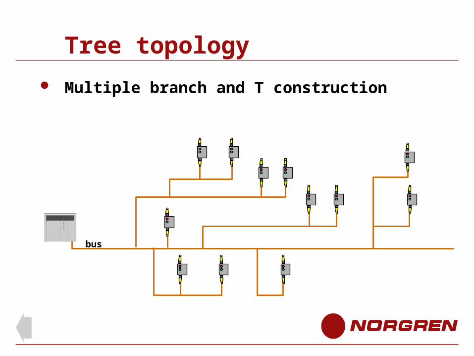
Tree topology
Multiple branch and T construction
bus
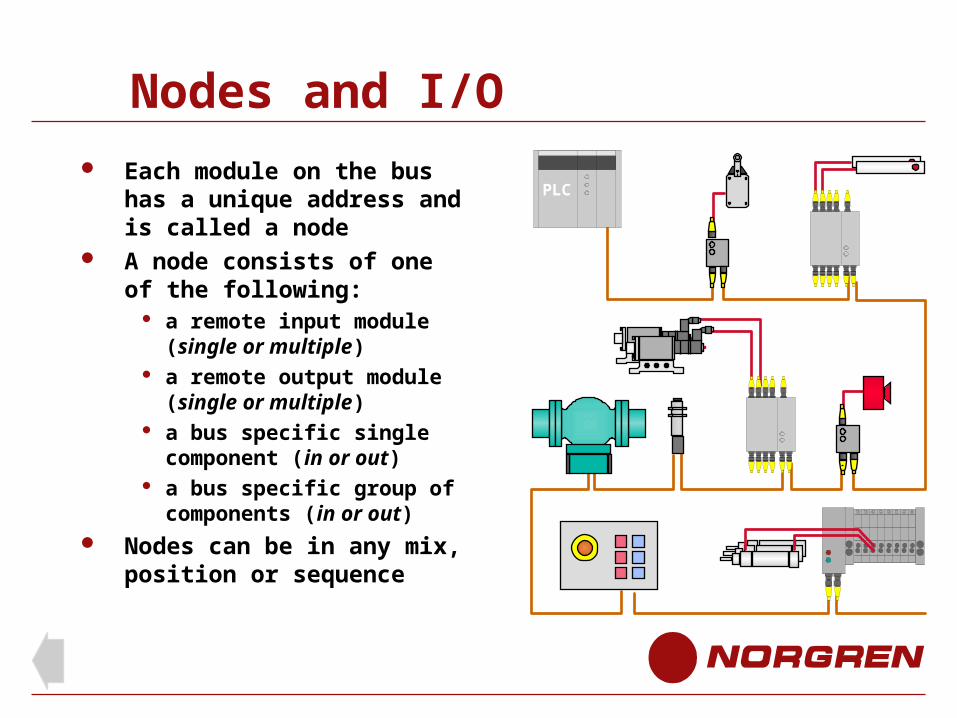
Nodes and I/O
Each module on the bus has a unique address and is called a node
A node consists of one of the following:
a remote input module (single or multiple)
a remote output module (single or multiple)
a bus specific single component (in or out)
a bus specific group of components (in or out)
Nodes can be in any mix, position or sequence
PLC
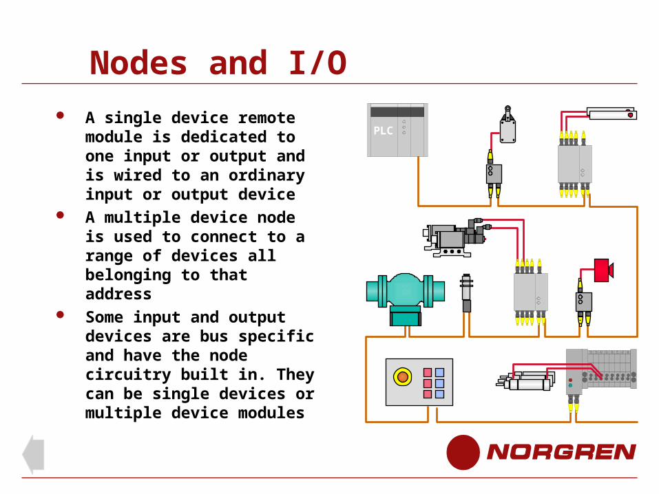
Nodes and I/O
A single device remote module is dedicated to one input or output and is wired to an ordinary input or output device
A multiple device node is used to connect to a range of devices all belonging to that address
Some input and output devices are bus specific and have the node circuitry built in. They can be single devices or multiple device modules
PLC
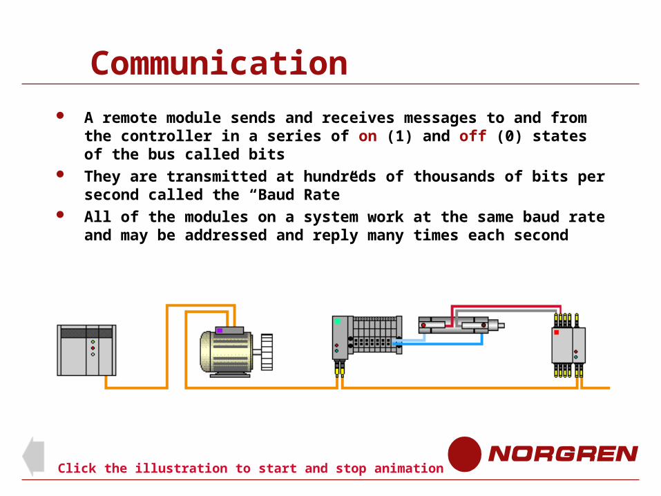
Communication
A remote module sends and receives messages to and from the controller in a series of on (1) and off (0) states of the bus called bits
They are transmitted at hundreds of thousands of bits per second called the “Baud Rate”
All of the modules on a system work at the same baud rate and may be addressed and reply many times each second
Click the illustration to start and stop animation
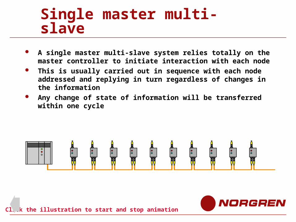
Single master multi-slave
A single master multi-slave system relies totally on the master controller to initiate interaction with each node
This is usually carried out in sequence with each node addressed and replying in turn regardless of changes in the information
Any change of state of information will be transferred within one cycle
Click the illustration to start and stop animation
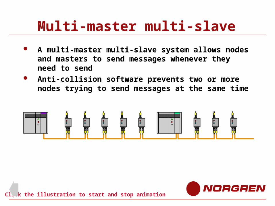
Multi-master multi-slave
A multi-master multi-slave system allows nodes and masters to send messages whenever they need to send
Anti-collision software prevents two or more nodes trying to send messages at the same time
Click the illustration to start and stop animation
Gateways
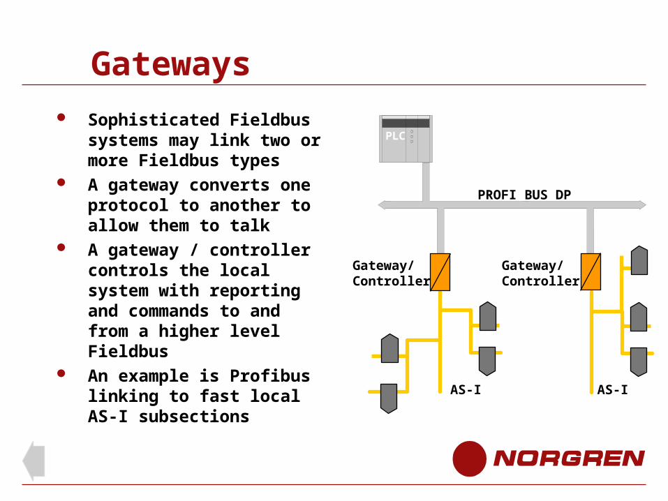
Sophisticated Fieldbus systems may link two or more Fieldbus types
A gateway converts one protocol to another to allow them to talk
A gateway / controller controls the local system with reporting and commands to and from a higher level Fieldbus
An example is Profibus linking to fast local AS-I subsections
PROFI BUS DP
AS-I
Gateway/Controller
Gateway/Controller
AS-I
PLC
Protocol
The protocol of a particular bus type is the set of rules that govern the structure and extent of messages and the order in which they can be issued
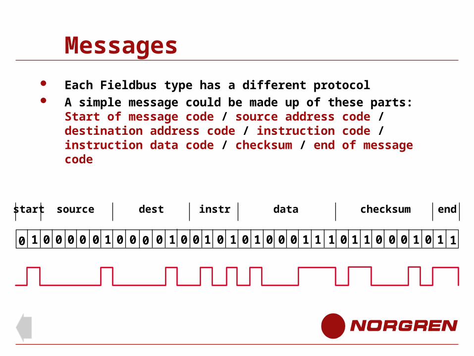
Messages Each Fieldbus type has a different protocol A simple message could be made up of these parts:
Start of message code / source address code / destination address code / instruction code / instruction data code / checksum / end of message code
0 11 0 0 0 0 0 1 0 0
start source dest instr data end
0 1 0 1 0 1 0 0 0 1 1 1 0 1 1 0 0 0 1 0 10 0 1 0
checksum
Speed A combination of baud rate, message length, number of nodes on the system,
and communication program will determine how often a slave node is polled by the master
Complex bus systems will have long message structures to contain the potentially complex messages. Simple messages will therefore be carried by more bits than they would on a simpler bus system
It is evident that a small simple bus system with a relatively low baud rate could be considerably faster than a large complex bus system with a high baud rate
Speed A change of state on the bus 0 to 1 or 1 to 0 will appear to be seen by all the
nodes on the bus at the same instant The duration of each bit is determined by the baud rate In theory with the following specification, all nodes can be individually addressed
and reply in about 4 milli seconds. (A baud rate of 500KBits/sec with a fixed 32 bit message length and 32 nodes on the bus)
In practice some of the input nodes will be reporting a change of state, this will involve the master controller in processing time before updating the output nodes
Programming The program within a master node (PLC or computer) can be considered
in two sections A front end program controlling the flow of bus messages in and out of
the serial port (programmed by the manufacturer or vendor)This is usually transparent to the user programmer who will not necessarily need knowledge of it
A user program defining the operation of the plant by calling outputs and reading inputs in a similar way as if the I/O were individually wired
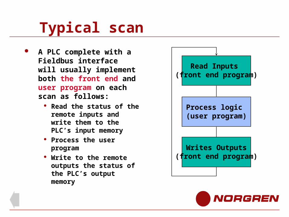
Typical scan
A PLC complete with a Fieldbus interface will usually implement both the front end and user program on each scan as follows:
Read the status of the remote inputs and write them to the PLC’s input memory
Process the user program
Write to the remote outputs the status of the PLC’s output memory
Read Inputs (front end program)
Process logic (user program)
Writes Outputs(front end program)
Configuration (front end)
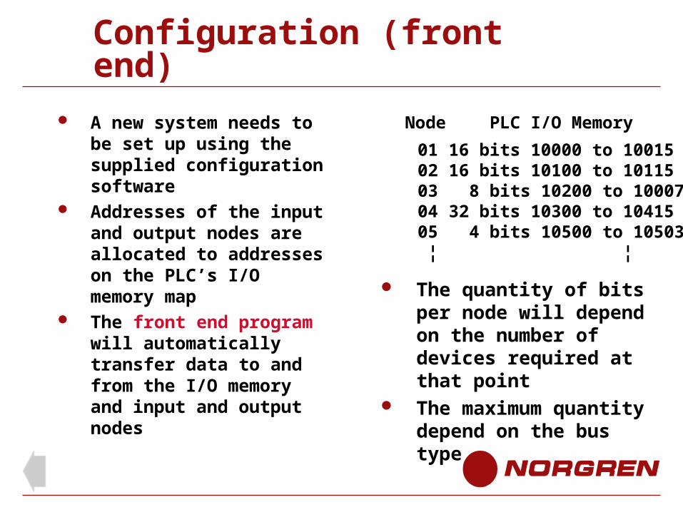
A new system needs to be set up using the supplied configuration software
Addresses of the input and output nodes are allocated to addresses on the PLC’s I/O memory map
The front end program will automatically transfer data to and from the I/O memory and input and output nodes
Node PLC I/O Memory
0102030405 ¦
16 bits 10000 to 1001516 bits 10100 to 10115 8 bits 10200 to 1000732 bits 10300 to 10415 4 bits 10500 to 10503 ¦
The quantity of bits per node will depend on the number of devices required at that point
The maximum quantity depend on the bus type
Configuration (front end)
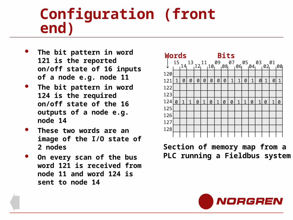
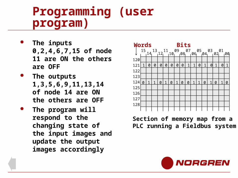
The bit pattern in word 121 is the reported on/off state of 16 inputs of a node e.g. node 11
The bit pattern in word 124 is the required on/off state of the 16 outputs of a node e.g. node 14
These two words are an image of the I/O state of 2 nodes
On every scan of the bus word 121 is received from node 11 and word 124 is sent to node 14
120
121
122
123
124
125
126
127
128
BitsWords15 13 11 09 07 05 03 01
0002040608101214
Section of memory map from a PLC running a Fieldbus system
0 1 1 0 1 0 1 0 0 1 1 0 01 1 0
1 0 0 0 0 0 0 0 1 1 0 1 10 0 1
Programming (user program)
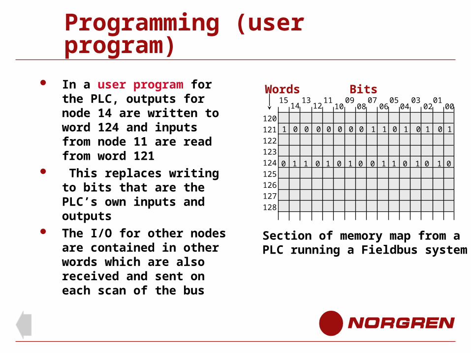
In a user program for the PLC, outputs for node 14 are written to word 124 and inputs from node 11 are read from word 121
This replaces writing to bits that are the PLC’s own inputs and outputs
The I/O for other nodes are contained in other words which are also received and sent on each scan of the bus
120
121
122
123
124
125
126
127
128
BitsWords15 13 11 09 07 05 03 01
0002040608101214
Section of memory map from a PLC running a Fieldbus system
0 1 1 0 1 0 1 0 0 1 1 0 01 1 0
1 0 0 0 0 0 0 0 1 1 0 1 10 0 1
Programming (user program)
The inputs 0,2,4,6,7,15 of node 11 are ON the others are OFF
The outputs 1,3,5,6,9,11,13,14 of node 14 are ON the others are OFF
The program will respond to the changing state of the input images and update the output images accordingly
BitsWords
Section of memory map from a PLC running a Fieldbus system
120
121
122
123
124
125
126
127
128
15 13 11 09 07 05 03 010002040608101214
0 1 1 0 1 0 1 0 0 1 1 0 01 1 0
1 0 0 0 0 0 0 0 1 1 0 1 10 0 1
Programming (user program)
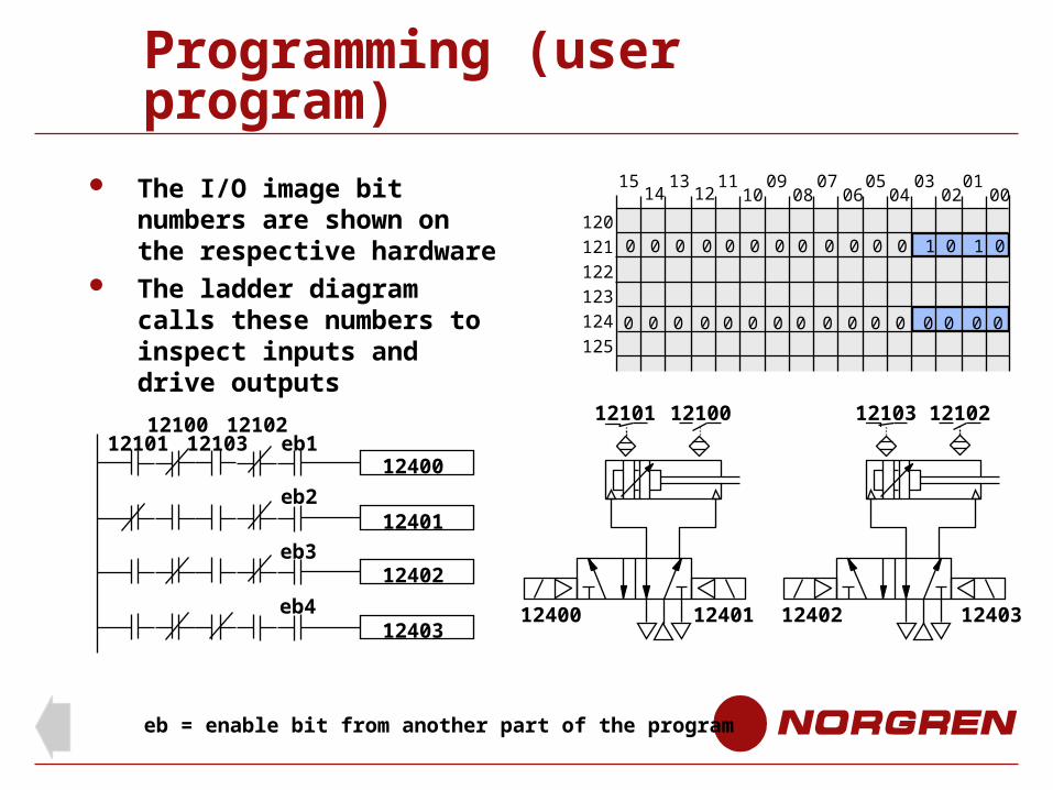
The I/O image bit numbers are shown on the respective hardware
The ladder diagram calls these numbers to inspect inputs and drive outputs
120
121
122
123
124
125
15 13 11 09 07 05 03 010002040608101214
0 0 0 0 0 0 0 0 0 0 0 0 00 0 0
0 0 0 0 0 0 0 0 0 0 0 0 01 1 0
12100 1210212101 12103
12400eb1
12401
12402
12403
eb2
eb3
eb4
12101 12100 12103 12102
12400 12401 12402 12403
eb = enable bit from another part of the program
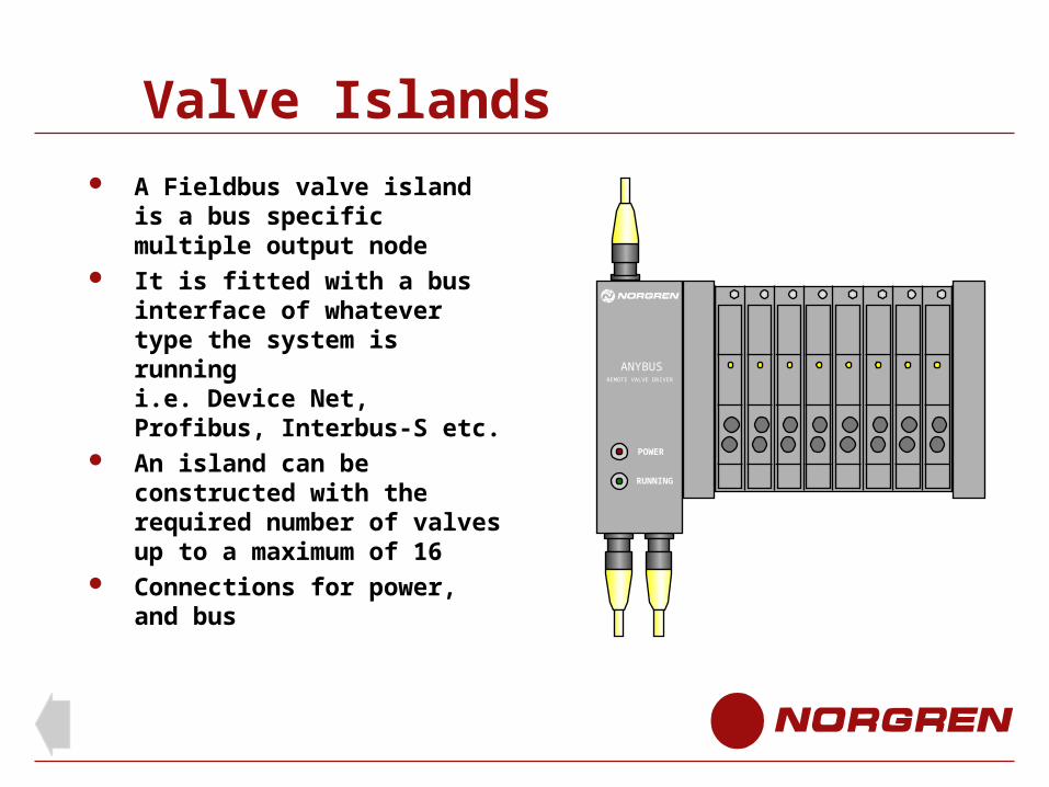
Valve Islands
A Fieldbus valve island is a bus specific multiple output node
It is fitted with a bus interface of whatever type the system is running i.e. Device Net, Profibus, Interbus-S etc.
An island can be constructed with the required number of valves up to a maximum of 16
Connections for power, and bus
POWER
RUNNING
ANYBUSREMOTE VALVE DRIVER
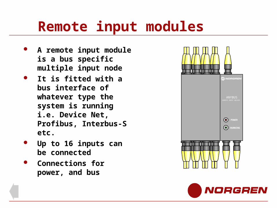
Remote input modules
A remote input module is a bus specific multiple input node
It is fitted with a bus interface of whatever type the system is running i.e. Device Net, Profibus, Interbus-S etc.
Up to 16 inputs can be connected
Connections for power, and bus
POWER
ANYBUSREMOTE INPUT DRIVER
RUNNING
Fieldbus Types
Fieldbus types
Valve islands and remote input modules are available for these Fieldbus types
Click the system titles for further details
Open systems
Device-Net Interbus-S Profibus DP and FMS AS-I Proprietary systems Sysmac (Omron) JETWay-R (Jetter) Pneubus (Norgren) Integrated PLC
DeviceNet
Fieldbus Type
DeviceNet
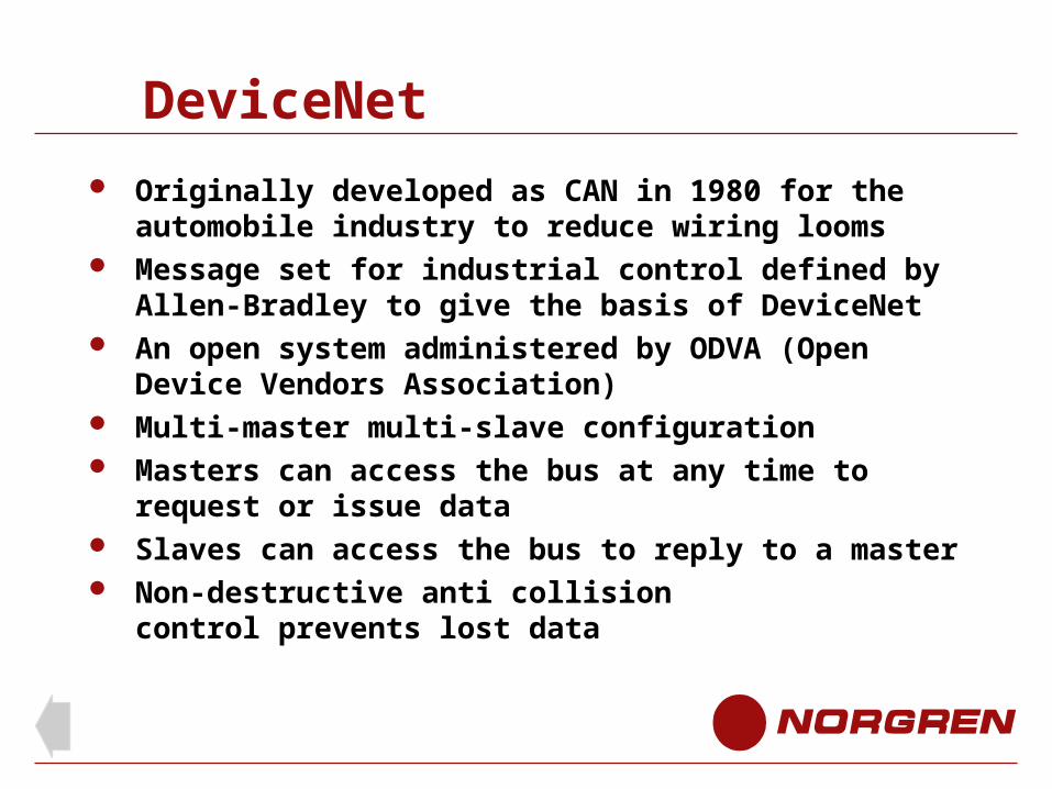
Originally developed as CAN in 1980 for the automobile industry to reduce wiring looms
Message set for industrial control defined by Allen-Bradley to give the basis of DeviceNet
An open system administered by ODVA (Open Device Vendors Association)
Multi-master multi-slave configuration Masters can access the bus at any time to request or
issue data Slaves can access the bus to reply to a master Non-destructive anti collision
control prevents lost data
DeviceNet
Protocol: DeviceNet (CAN)
Norgren remote input module: max. 16 inputs
Norgren remote output driver: max. 16 outputs
Topology: Line (May contain spurs (10ft each maximum)
Configuration: Multi- masters, multi-slaves
Communication (CAN standard)
Max. Baud rate500 kBits/sec
Cable length at max. Baud rate 100m
Nodes per installation:64
Max I/O per node 32 (2048 I/O total)
Cable: twisted pair, with screen and 24V.d.c. power line
End of DeviceNet
InterBus-S
Fieldbus Type
InterBus-S
A ring system with both the forward and return data lines contained in one cable running through each node. This gives the appearance of a line
Uses point to point transmission so each node is a repeater. This allows up to 400m between each device and an overall distance of 13 km
A secondary ring bus (local bus) can be branched from any point using a bus terminal module giving the installation a tree like structure
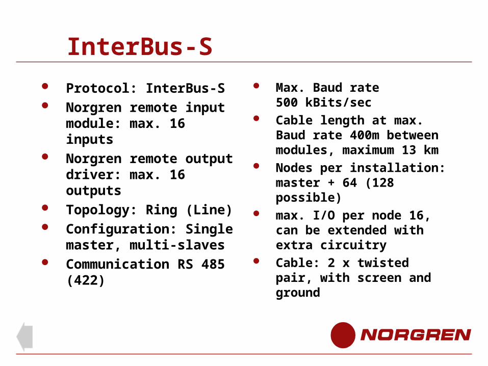
InterBus-S
Protocol: InterBus-S Norgren remote input
module: max. 16 inputs Norgren remote output
driver: max. 16 outputs Topology: Ring (Line) Configuration: Single
master, multi-slaves Communication RS 485
(422)
Max. Baud rate500 kBits/sec
Cable length at max. Baud rate 400m between modules, maximum 13 km
Nodes per installation:master + 64 (128 possible)
max. I/O per node 16, can be extended with extra circuitry
Cable: 2 x twisted pair, with screen and ground

End of InterBus-S
PROFIBUS ( Process Field Bus)
Fieldbus Type
PROFIBUS
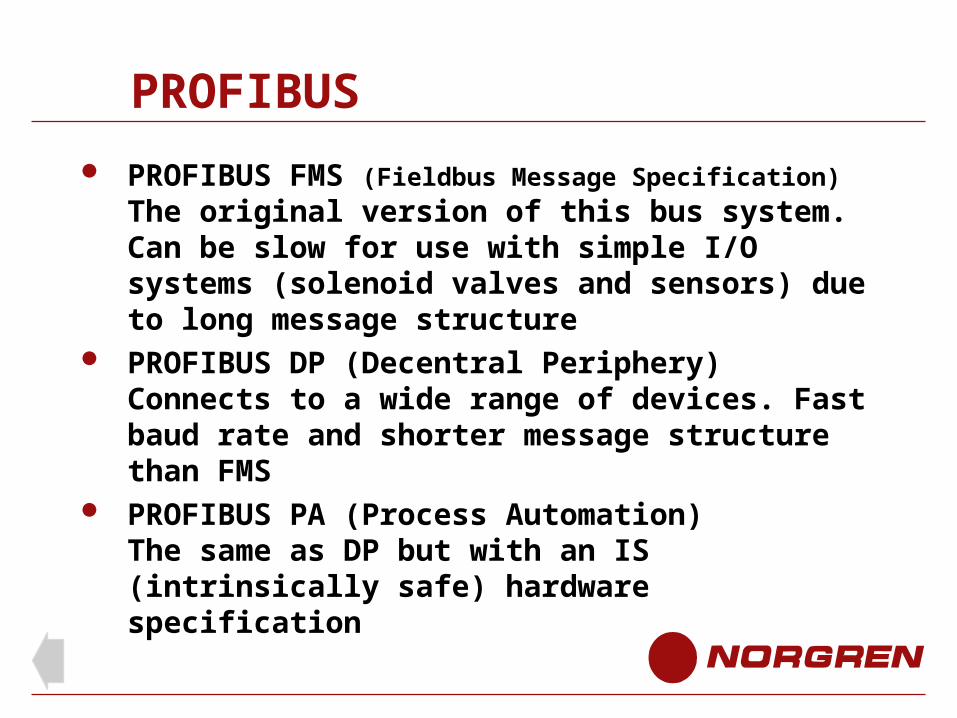
PROFIBUS FMS (Fieldbus Message Specification)
The original version of this bus system. Can be slow for use with simple I/O systems (solenoid valves and sensors) due to long message structure
PROFIBUS DP (Decentral Periphery)Connects to a wide range of devices. Fast baud rate and shorter message structure than FMS
PROFIBUS PA (Process Automation)The same as DP but with an IS (intrinsically safe) hardware specification
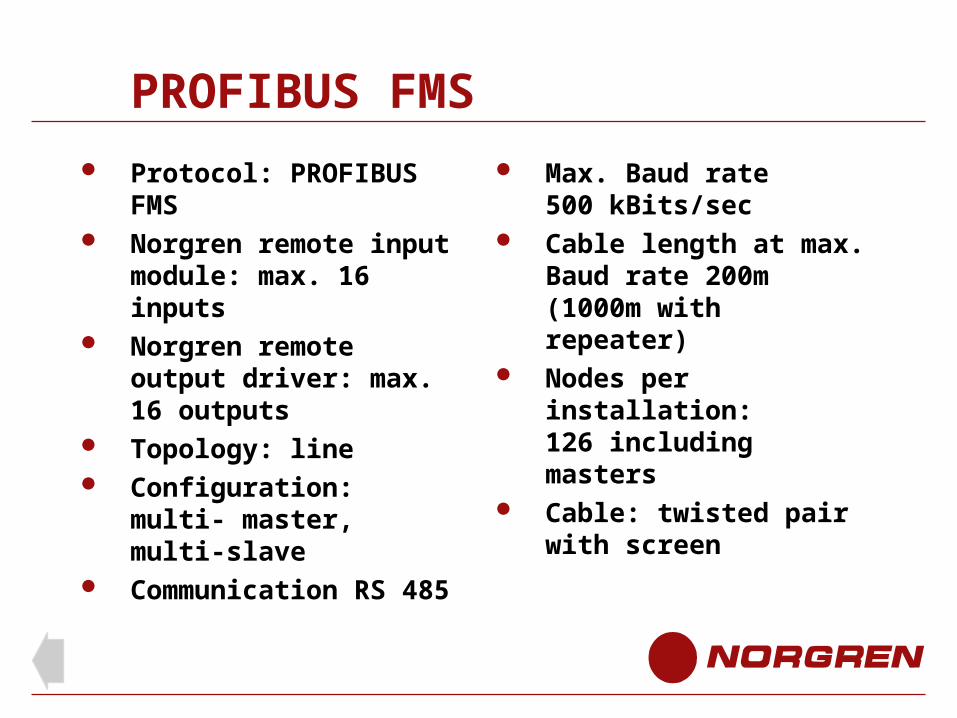
PROFIBUS FMS
Protocol: PROFIBUS FMS Norgren remote input
module: max. 16 inputs Norgren remote output
driver: max. 16 outputs Topology: line Configuration: multi-
master, multi-slave Communication RS 485
Max. Baud rate500 kBits/sec
Cable length at max. Baud rate 200m (1000m with repeater)
Nodes per installation:126 including masters
Cable: twisted pair with screen
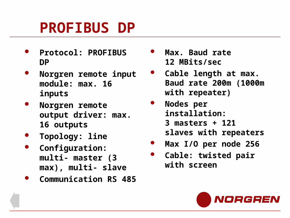
PROFIBUS DP
Protocol: PROFIBUS DP Norgren remote input
module: max. 16 inputs Norgren remote output
driver: max. 16 outputs Topology: line Configuration: multi-
master (3 max), multi- slave
Communication RS 485
Max. Baud rate12 MBits/sec
Cable length at max. Baud rate 200m (1000m with repeater)
Nodes per installation:3 masters + 121 slaves with repeaters
Max I/O per node 256 Cable: twisted pair with
screen
End of PROFIBUS
AS-Interface (Actuator Sensor Interface)
Fieldbus type
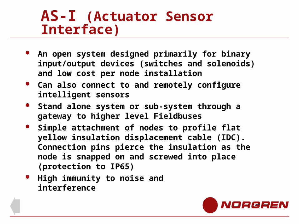
AS-I (Actuator Sensor Interface)
An open system designed primarily for binary input/output devices (switches and solenoids) and low cost per node installation
Can also connect to and remotely configure intelligent sensors
Stand alone system or sub-system through a gateway to higher level Fieldbuses
Simple attachment of nodes to profile flat yellow insulation displacement cable (IDC). Connection pins pierce the insulation as the node is snapped on and screwed into place (protection to IP65)
High immunity to noise and interference
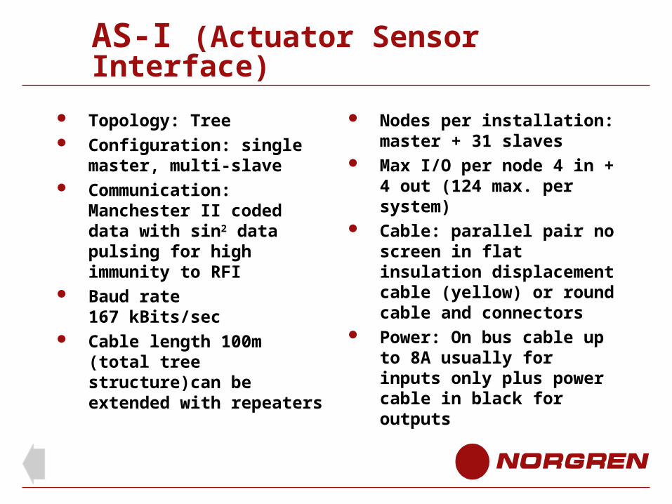
AS-I (Actuator Sensor Interface)
Topology: Tree Configuration: single
master, multi-slave Communication:
Manchester II coded data with sin2 data pulsing for high immunity to RFI
Baud rate167 kBits/sec
Cable length 100m (total tree structure)can be extended with repeaters
Nodes per installation:master + 31 slaves
Max I/O per node 4 in + 4 out (124 max. per system)
Cable: parallel pair no screen in flat insulation displacement cable (yellow) or round cable and connectors
Power: On bus cable up to 8A usually for inputs only plus power cable in black for outputs
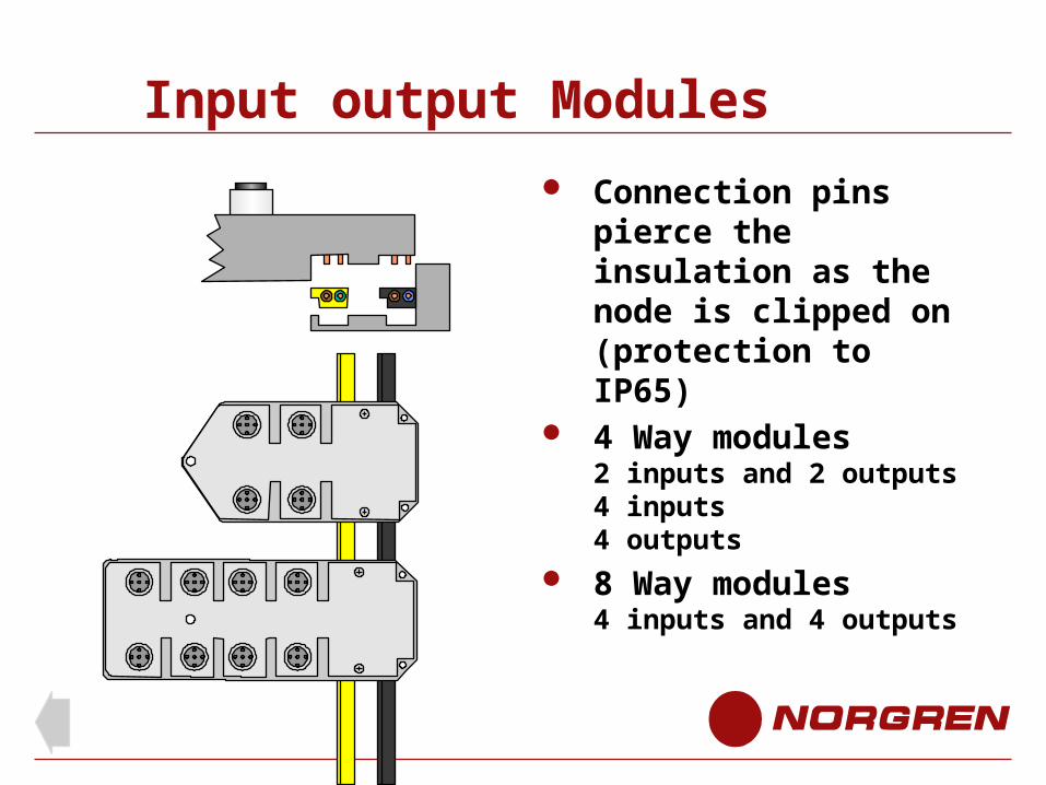
Input output Modules
Connection pins pierce the insulation as the node is clipped on (protection to IP65)
4 Way modules2 inputs and 2 outputs4 inputs4 outputs
8 Way modules4 inputs and 4 outputs
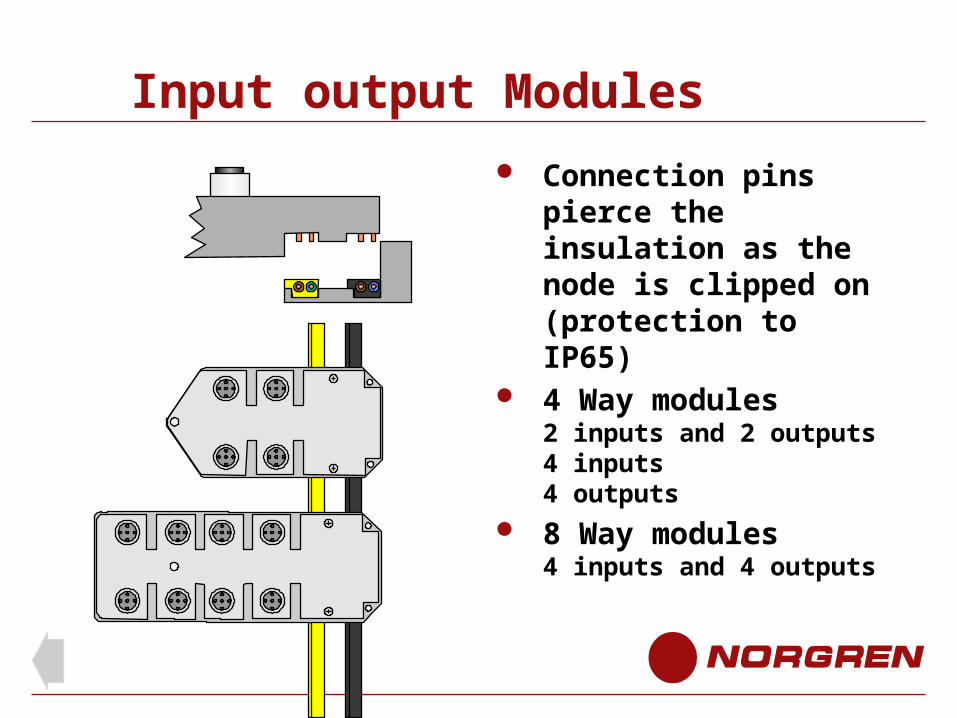
Input output Modules
Connection pins pierce the insulation as the node is clipped on (protection to IP65)
4 Way modules2 inputs and 2 outputs4 inputs4 outputs
8 Way modules4 inputs and 4 outputs
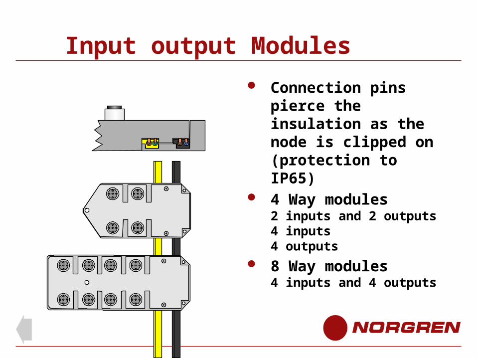
Input output Modules
Connection pins pierce the insulation as the node is clipped on (protection to IP65)
4 Way modules2 inputs and 2 outputs4 inputs4 outputs
8 Way modules4 inputs and 4 outputs
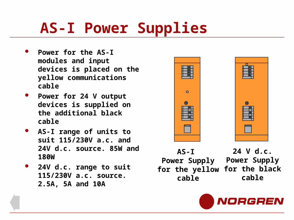
AS-I Power Supplies
Power for the AS-I modules and input devices is placed on the yellow communications cable
Power for 24 V output devices is supplied on the additional black cable
AS-I range of units to suit 115/230V a.c. and 24V d.c. source. 85W and 180W
24V d.c. range to suit 115/230V a.c. source. 2.5A, 5A and 10A
AS-I Power Supplyfor the yellow
cable
24 V d.c.Power Supplyfor the black
cable
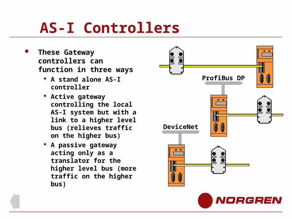
AS-I Controllers
These Gateway controllers can function in three ways
A stand alone AS-I controller
Active gateway controlling the local AS-I system but with a link to a higher level bus (relieves traffic on the higher bus)
A passive gateway acting only as a translator for the higher level bus (more traffic on the higher bus)
DeviceNet
ProfiBus DP
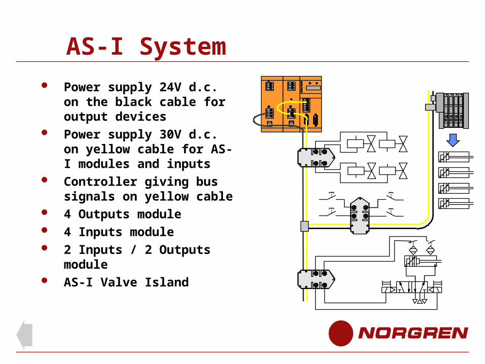
AS-I System
Power supply 24V d.c. on the black cable for output devices
Power supply 30V d.c. on yellow cable for AS-I modules and inputs
Controller giving bus signals on yellow cable
4 Outputs module 4 Inputs module 2 Inputs / 2 Outputs
module AS-I Valve Island
End of AS-Interface
Sysmac
Proprietary Fieldbus Type (Omron)
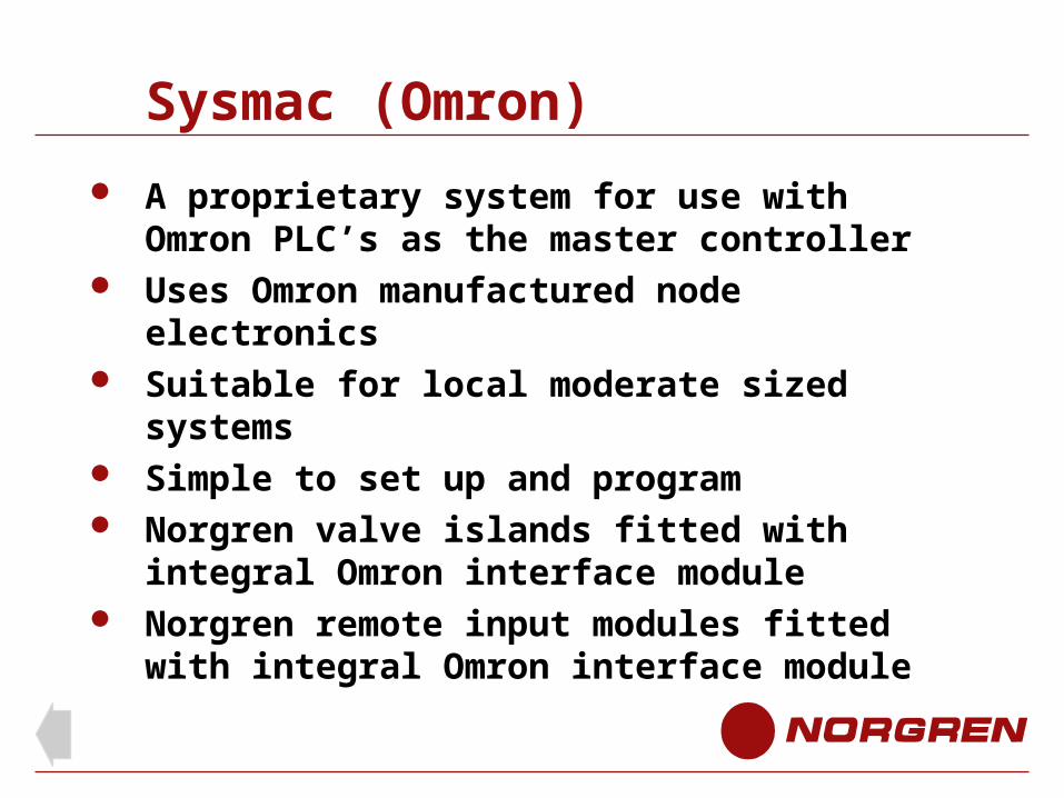
Sysmac (Omron)
A proprietary system for use with Omron PLC’s as the master controller
Uses Omron manufactured node electronics Suitable for local moderate sized systems Simple to set up and program Norgren valve islands fitted with integral Omron
interface module Norgren remote input modules fitted with
integral Omron interface module
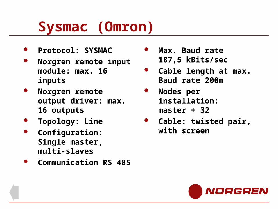
Sysmac (Omron)
Protocol: SYSMAC Norgren remote input
module: max. 16 inputs Norgren remote output
driver: max. 16 outputs Topology: Line Configuration: Single
master, multi-slaves Communication RS 485
Max. Baud rate187,5 kBits/sec
Cable length at max. Baud rate 200m
Nodes per installation:master + 32
Cable: twisted pair, with screen
End of Sysmac
JETWay-R
Fieldbus Type
JETWay-R
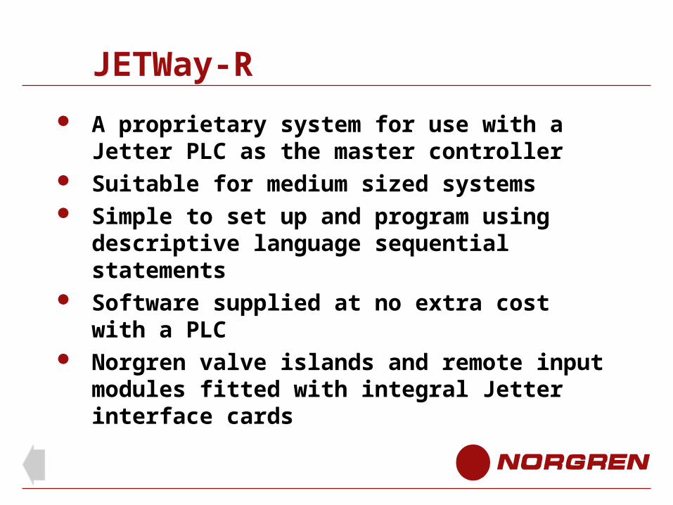
A proprietary system for use with a Jetter PLC as the master controller
Suitable for medium sized systems Simple to set up and program using descriptive
language sequential statements Software supplied at no extra cost with a PLC Norgren valve islands and remote input modules
fitted with integral Jetter interface cards
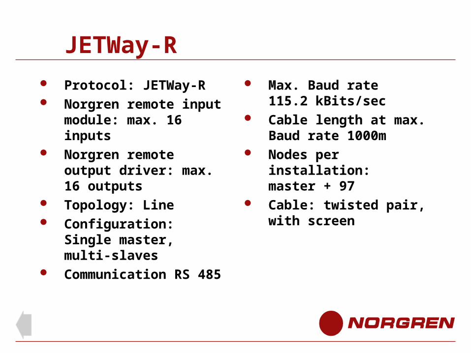
JETWay-R
Protocol: JETWay-R Norgren remote input
module: max. 16 inputs Norgren remote output
driver: max. 16 outputs Topology: Line Configuration: Single
master, multi-slaves Communication RS 485
Max. Baud rate115.2 kBits/sec
Cable length at max. Baud rate 1000m
Nodes per installation:master + 97
Cable: twisted pair, with screen
End of JETWay-R
Pneu Bus
Fieldbus Type
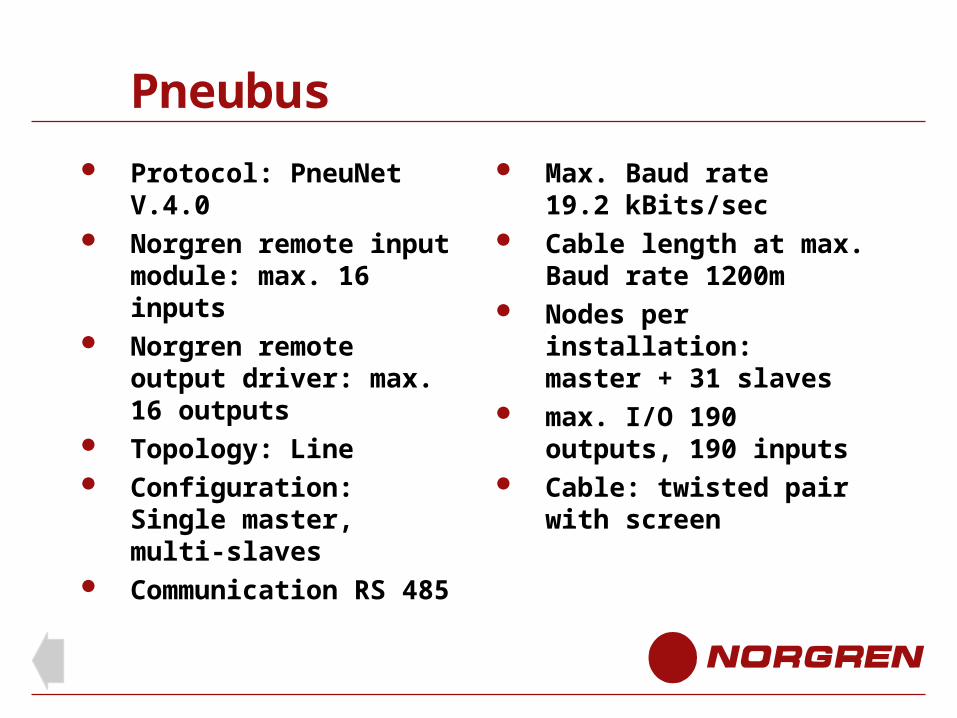
Pneubus
Protocol: PneuNet V.4.0 Norgren remote input
module: max. 16 inputs Norgren remote output
driver: max. 16 outputs Topology: Line Configuration: Single
master, multi-slaves Communication RS 485
Max. Baud rate19.2 kBits/sec
Cable length at max. Baud rate 1200m
Nodes per installation:master + 31 slaves
max. I/O 190 outputs, 190 inputs
Cable: twisted pair with screen

End of Pneu Bus
Integrated PLC and Valve Island
Stand alone or bus master
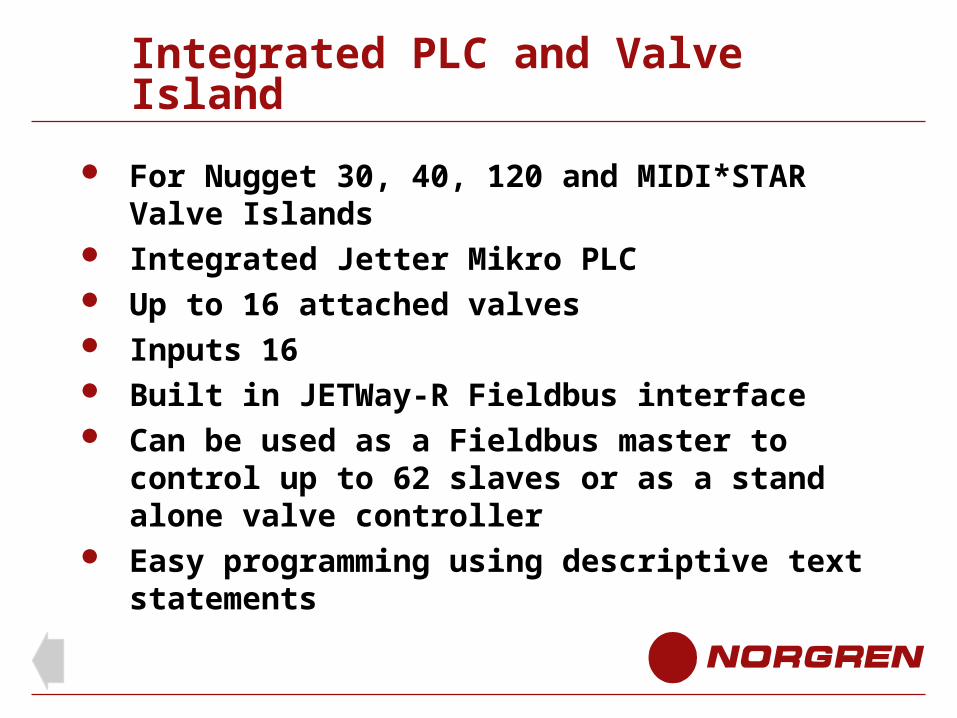
Integrated PLC and Valve Island
For Nugget 30, 40, 120 and MIDI*STAR Valve Islands
Integrated Jetter Mikro PLC Up to 16 attached valves Inputs 16 Built in JETWay-R Fieldbus interface Can be used as a Fieldbus master to control up
to 62 slaves or as a stand alone valve controller Easy programming using descriptive text
statements
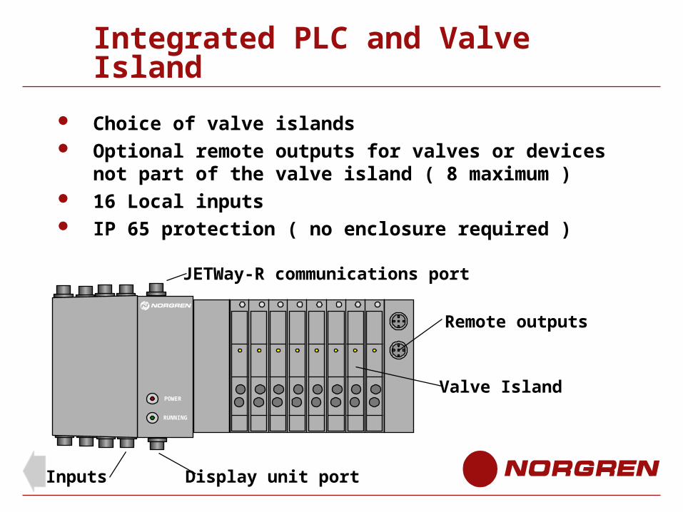
Integrated PLC and Valve Island
POWER
RUNNING
Choice of valve islands Optional remote outputs for valves or devices not part of
the valve island ( 8 maximum ) 16 Local inputs IP 65 protection ( no enclosure required )
Inputs
Valve Island
Remote outputs
Display unit port
JETWay-R communications port
End of Integrated PLC
End


