Embed Size (px)
Citation preview
Fax Service Class 1 and Fax Service Class 1.0
Developer’s Guide

Fax Class 1 and Class 1.0 Developer’s Guide PN S000262C, Rev. C 11/01/07
Copyright © 2002-7 by Multi-Tech Systems, Inc. This publication may not be reproduced, in whole or in part, without prior expressed written permission from Multi-Tech Systems, Inc. All rights reserved. Multi-Tech Systems, Inc. makes no representations or warranties with respect to the contents hereof and specifically disclaims any implied warranties of merchantability or fitness for any particular purpose. Furthermore, Multi-Tech Systems, Inc. reserves the right to revise this publication and to make changes from time to time in the content hereof without obligation of Multi-Tech Systems, Inc. to notify any person or organization of such revisions or changes.
Revisions Revision Level Date Description A 07/26/02 First release. B 04/18/07 Updated the Technical Support contact list. C 11/01/07 Removed France from Technical Support contact list.
Trademarks The Multi-Tech logo is a trademarks of Multi-Tech Systems, Inc. Other trademarks or trade names mentioned in this publication belong to their respective owners.
World Headquarters Multi-Tech Systems, Inc. 2205 Woodale Drive Mounds View, Minnesota 55112 Phone: 763-785-3500 or 800-328-9717 Fax: 763-785-9874 Technical Support Country By Email By Phone Europe, Middle East, Africa: [email protected] (44) 118 959 7774 U.S., Canada, all others: [email protected] (800) 972-2439 or (763) 717-5863 Internet Address: http://www.multitech.com

Table of Contents
CHAPTER 1 – INTRODUCTION TO FAX SERVICE CLASS 1 AND SERVICE CLASS 1.0....................................................4
OVERVIEW .................................................................................................................................................................4 V.34 MODES AND NON-V.34 MODES.........................................................................................................................5 A NOTE ABOUT MODEMS AND THE CLASSES THEY SUPPORT ....................................................................................5
CHAPTER 2 – FAX SERVICE CLASS 1............................................................................................................................6
Call Initiation ........................................................................................................................................................6 Originated Calls ....................................................................................................................................................6 Answered Calls ......................................................................................................................................................6 Call Online ............................................................................................................................................................6 Call Termination....................................................................................................................................................6 DLE Sequences ......................................................................................................................................................6
CLASS 1 COMMAND REFERENCE ................................................................................................................................7 CLASS 1 FAX COMMAND SUMMARY ..........................................................................................................................7 CLASS 1 FAX COMMANDS DETAIL .............................................................................................................................9
CHAPTER 3 – FAX SERVICE CLASS 1.0.......................................................................................................................16
Initial V.34 Rate Controls and Indications ..........................................................................................................16 Initial V.34 Rate Indication .................................................................................................................................16 Call Initiation ......................................................................................................................................................17 Call Online ..........................................................................................................................................................17 Call Termination..................................................................................................................................................17 Host Initiated Termination ..................................................................................................................................17 Modem Initiated Termination ..............................................................................................................................17 DLE Sequences ....................................................................................................................................................18 Host-Modem Data ...............................................................................................................................................19 Host to Modem Messages ....................................................................................................................................19 Modem to Host Messages ....................................................................................................................................19 HDLC Frame Data..............................................................................................................................................19
CLASS 1.0 SAMPLE SESSIONS ...................................................................................................................................20 Sample Session 1 – Originate and Send a Two-Page Facsimile with V.34 .........................................................21 Sample Session 2 –Answer and Receive a Two-Page Facsimile with V.34 .........................................................23
INDEX ........................................................................................................................................................................24

Chapter 1 – Introduction
Multi-Tech Systems, Inc. Fax Developer’s Guide 4
CHAPTER 1 – INTRODUCTION TO FAX SERVICE CLASS 1 AND SERVICE CLASS 1.0
Overview Service Class 1 and Class 1.0 are command sets/protocols that are designed to allow a host computer to control the sending/receiving of a fax to the lowest level. When using Class 1/1.0, the host must implement all of the T.30/T.4 protocol procedures. This is in contrast to Service Classes 2/2.0/21, where the modem implements all of T.30/T.4 protocol procedures. While this is an extra burden on the host, it means that the host software can accommodate any new fax features that the software writer desires (when they desire it) and allows the fixing of any fax incompatibilities without having to rely on the fax modem vendor to provide them.
Service Class 1 is used to support faxing at data rates of 14,400 baud and below. Service Class 1.0 is used to support faxing at data rates of 2400 to 33,600 when doing modem modulation V.34. Only newer fax machines support this modulation (these fax modems are sometimes referred to as Super G3).
The two service classes are actually very different in operation, but do share some similarities due to their nature as low-level fax support protocols. Both need to send and receive HDLC framed data and both need to switch between a control (low-speed) data channel and primary (high-speed) data channel.
Service Class 1 is implemented by going in and out of data mode to transmit and receive frames or unframed data. A command is used to put the modem into data mode (e.g., AT+FTH=3 will tell the modem to start its transmitter at 300 baud in HDLC mode), and then a CONNECT message is issued to tell the host that the modem is now in data transfer state. After all the necessary data is transferred (e.g., The HDLC frame is sent/received), then the modem goes back into command mode but the modem is still off-hook.
Services Class 1.0 is implemented by just going into data mode after the connection is made and staying there until the call is completed. Data is just transferred to and from the modem like when the modem is in a regular data mode connection, except that DLE shielded commands are used to control the modem's behavior.
Services Class 1 uses AT commands to control the fax modem's behavior and Service Class 1.0 uses DLE-shielded characters to control the fax modem's behavior. Below is a table of the capabilities and how they are implemented in Class 1 and Class 1.0.
Table of Capabilities Note: For a description of DLE, see the section on DLE Sequences on the next page.
Capability Class 1 Class 1.0 Sending HDLC frames AT+RTH=, wait for CONNECT,
sending frame data followed by DLE-ETX sending frame data followed by DLE-ETX
Receiving HDLC frames AT+FRH=, wait for CONNECT, receive frame data terminated by DLE-ETX
Receive frame data terminated by DLE-ETX
Sending Unframed data AT+FTM=,wait for CONNECT, sending data followed by DLE-ETX
Not needed
Receiving Unframed data AT+FRM=, wait for CONNECT, receive data followed by DLE-ETX.
Not needed
Sending/Receiving Silence AT+FTS=,AT+FRS= Not needed Switch to control channel AT+FTH=3, AT+FRH=3 DLE-n, or DLE-o Switch to primary channel AT+FTH=(not 3), AT+FRH=(not 3),
AT+FTM=, AT+RM= DLE-p, through DLE-}
Indication of a switch to data mode
CONNECT DLE-k, or DLE-m
Indication that remote is gone Not possible DLE-Ctrl-D

Chapter 1 – Introduction
Multi-Tech Systems, Inc. Fax Developer’s Guide 5
V.34 Modes and Non-V.34 Modes Just because the host sets the modem to Service Class 1.0 doesn't mean that the host uses the Service Class 1.0 protocol to send the fax. That occurs only if the remote fax machine is also V.34 capable.
Also, by initializing the modem to Service Class 1 instead of 1.0, the host has causes the local modem to be incapable of V.34 connections.
If the modem is initialized to Service Class 1.0 and the initial connection is made, then whatever type of connection is negotiated between the local and remote fax modems dictates which fax protocol is used (Service Class 1 or 1.0) between the host computer and the local modem.
Below is a table of the possible combinations and what the modem response is in those cases.
Local Modem Setting Remote Capabilities Modem Indication on Receipt of Carrier
Service Class Protocol to Use
AT+FCLASS=1 Non-V.34 capable or V.34 capable CONNECT 1 AT+FCLASS=1.0 Non-V.34 capable CONNECT 1 AT+FCLASS=1.0 V.34 capable +F34: n,m
CONNECT 1.0
A Note About Modems and the Classes They Support To determine which command Class or Classes your modem supports, use the AT command:
+FCLASS=? (see page 9)
• If your modem supports Class 1 fax commands, the following chapter applies. • If your modem supports Class 1.0 fax commands, see Chapter 3. • If your modem supports Classes 2/2.0/2.1, see the separate Class 2/2.0/2.1 document.

Chapter 2 – Fax Service Class 1
Multi-Tech Systems, Inc. Fax Developer’s Guide 6
CHAPTER 2 – FAX SERVICE CLASS 1 Fax Service Class 1 consists of a set of six AT commands that control how the modem acts when online. Below is a table of the commands and their descriptions.
Command Description AT+FTH=n Transmit a HDLC frame using modulation n AT+FRH=n Receive a HDLC frame using modulation n AT+FTM=n Transmit unframed data using modulation n AT+FRM=n Receive unframed data using modulation n AT+FTS=hs Transmit silence for hs hundredths of seconds AT+FRS=hs Receive hs hundredths of seconds of silence before completing
Once the modem has made it into online mode, these commands can be used in any order (but in order to send or receive a fax, they must be used in a particular order as dictated by T.30). The call is terminated when an ATH is issued (which puts the modem back on hook).
Call Initiation A Service Class 1 call starts by either dialing or answering an incoming call. Because the transition to online mode is different for each, they will be described separately.
Originated Calls When the modem dials in Service Class 1, it acts as if it had been given an AT+FRH=3 command as well (it is implied by the dial). If a remote V.21 carrier is detected after the dial a CONNECT message is issued by the modem and the received frames may be received. After all the frames are received, an OK is issued and the modem is now in the online state.
Answered Calls When the modem answers in Service Class 1, it acts as if it had been given an AT+FTH=3 command as well (it is implied by the ATA). A CONNECT response is then issued and the host should send the frames that it wants to send to the remote fax modem. When the final frame is sent, an OK issued and the modem is now in online state.
Call Online When the modem is in online state, any of the six Service Class 1 commands can be issued. In this state the modem is neither transmitting nor receiving any carrier signals (it is silent on the phone line).
Call Termination When the modem is in online state, an ATH command is used to terminate the call.
DLE Sequences DLE sequences are sequences of data sent in data mode that indicate control information. The sequence consists of two characters, the first being a DLE (a hex 10 value) and the second being a control value. In order that an ordinary DLE byte can be sent, the sequence DLE-DLE is sent to send one DLE byte. Below is a table of the acceptable DLE sequences.
Sequence Hex Values Description DLE-DLE 10-10 Equivalent to one DLE in data stream DLE-SUB 10-1A Equivalent to two DLEs DLE-ETX 10-03 Indicates end of frame or data stream.
Chapter 2 – Fax Service Class 1
Multi-Tech Systems, Inc. Fax Developer’s Guide 7
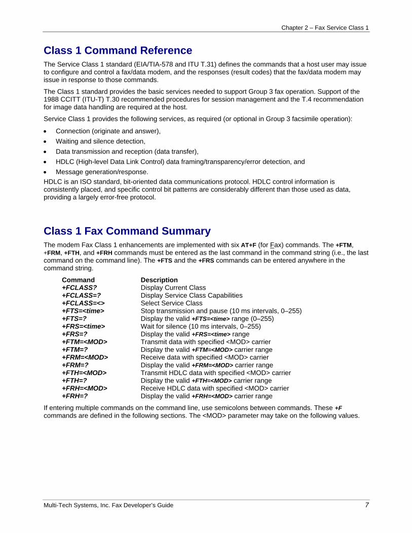
Class 1 Command Reference The Service Class 1 standard (EIA/TIA-578 and ITU T.31) defines the commands that a host user may issue to configure and control a fax/data modem, and the responses (result codes) that the fax/data modem may issue in response to those commands.
The Class 1 standard provides the basic services needed to support Group 3 fax operation. Support of the 1988 CCITT (ITU-T) T.30 recommended procedures for session management and the T.4 recommendation for image data handling are required at the host.
Service Class 1 provides the following services, as required (or optional in Group 3 facsimile operation):
• Connection (originate and answer), • Waiting and silence detection, • Data transmission and reception (data transfer), • HDLC (High-level Data Link Control) data framing/transparency/error detection, and • Message generation/response. HDLC is an ISO standard, bit-oriented data communications protocol. HDLC control information is consistently placed, and specific control bit patterns are considerably different than those used as data, providing a largely error-free protocol.
Class 1 Fax Command Summary The modem Fax Class 1 enhancements are implemented with six AT+F (for Fax) commands. The +FTM, +FRM, +FTH, and +FRH commands must be entered as the last command in the command string (i.e., the last command on the command line). The +FTS and the +FRS commands can be entered anywhere in the command string.
Command Description +FCLASS? Display Current Class +FCLASS=? Display Service Class Capabilities +FCLASS=<> Select Service Class +FTS=<time> Stop transmission and pause (10 ms intervals, 0–255) +FTS=? Display the valid +FTS=<time> range (0–255) +FRS=<time> Wait for silence (10 ms intervals, 0–255) +FRS=? Display the valid +FRS=<time> range +FTM=<MOD> Transmit data with specified <MOD> carrier +FTM=? Display the valid +FTM=<MOD> carrier range +FRM=<MOD> Receive data with specified <MOD> carrier +FRM=? Display the valid +FRM=<MOD> carrier range +FTH=<MOD> Transmit HDLC data with specified <MOD> carrier +FTH=? Display the valid +FTH=<MOD> carrier range +FRH=<MOD> Receive HDLC data with specified <MOD> carrier +FRH=? Display the valid +FRH=<MOD> carrier range
If entering multiple commands on the command line, use semicolons between commands. These +F commands are defined in the following sections. The <MOD> parameter may take on the following values.

Chapter 2 – Fax Service Class 1
Multi-Tech Systems, Inc. Fax Developer’s Guide 8
Fax MOD (Modulation) Parameter Values Value Modulation Speed (bps) Requirements 3 V.21 ch.`2 300 required for +FTH & +FRH 24 V.27ter 2400 required for +FTM & +FRM 48 V.27ter 4800 required for +FTM & +FRM 72 V.29 7200 optional 73 V.17 7200 optional 74 V.17 w/st 7200 optional 96 V.29 9600 optional 97 V.17 14400 optional 98 V.17 w/st 14400 optional 121 V.17 or V.33 12000 optional 122 V.17 w/st 12000 optional 145 V.17 or V.33 14400 optional 146 V.17 w/st 14400 optional
All other codes are reserved. "V.17 w/st" indicates V.17 short training (aka, "quick train"). All of the above commands return an ERROR result code if entered when the modem is on-hook.
Use the command syntax +<command>=? to ask for the valid range of values supported. For example, if you entered +FTH=?, the Class 1 modem would return 3 (a Class 2 modem would return 3,24,48,72,73, 74, 96).

Chapter 2 – Fax Service Class 1
Multi-Tech Systems, Inc. Fax Developer’s Guide 9
Class 1 Fax Commands Detail +FCLASS? Syntax: +FCLASS? <CR> Valid Values: 0, 1, 2 Default: 0 (data modem) Result Codes: OK if the command is accepted; ERROR if the parameter value is out of range. Display Current Class: Displays the current Service Class of the modem, as shown below.
Result Code Meaning 0 Indicates a data modem 1 Indicates a Service Class 1 (fax/data) modem 1.0 Indicates a Service Class 1.0 modem 2 Indicates a non-standard Class 2 modem (based on an early draft of the Class 2.0 2.0 Indicates a Service Class 2.0 (fax/data) modem 2.1 Indicates a Service class 2.1 (fax/data) modem
+FCLASS=? Syntax: +FCLASS=? <CR> Valid Values: 0, 1 (other values are reserved) Default: 0 (data modem) Result Codes: OK if the command is accepted; ERROR if the parameter value is out of range. Display Service Class Capabilities: Displays the set of Service Class capabilities supported by the modem from the list of values (e.g., 0,1 for a modem supporting data communications plus fax Service Class 1). This command returns the service class or classes available with the modem. The modem returns a list of all supported values, separated by commas if more than one class is supported. For example, a modem supporting data communications and Class 1 fax would respond with "0,1". +FCLASS=<value> Syntax: +FCLASS=<value> <CR> Valid Values: 0, 1, 2 Default: 0 (data mode) Result Codes: OK if the command is accepted; ERROR if the parameter value is out of range. Select Service Class: Selects the Service Class for the modem. The command options are: +FCLASS=0 Select Data mode +FCLASS=1 Select Fax Class 1 operation +FCLASS=2 Select Fax Class 2 operation Example: To configure the modem for Class 1 fax operation, enter the command AT+FCLASS=1 and press
Enter. The modem will then accept Class 1 commands. +FTS=<time> Syntax: +FTS=<time> <CR> Valid Values: <time> = 0-255 in 10 ms intervals Default: 0 Result Codes: OK if the command is accepted; ERROR if the parameter value is out of range. Stop Transmission and Wait: Causes the modem to stop any transmission and then wait for the amount of time specified by <time>, then send an OK result code to the host. If this command is entered with the modem on-hook, the ERROR result code is displayed. The main function of +FTS is to enforce the 75+/–20 ms of silent time needed between modulation changes. Note: The +FTS= command can be entered anywhere in the command string.

Chapter 2 – Fax Service Class 1
Multi-Tech Systems, Inc. Fax Developer’s Guide 10
+FTS=? Syntax: +FTS=? <CR> Valid Values: <time> = 0–255 in 10 ms intervals Default: 0 Result Codes: The current range of values supported by the modem. Display the Wait-for-Silent Time: Causes the modem to display the valid (supported) range of time intervals specified by the +FTS=<time> command. +FRS=<time> Syntax: +FRS=<time> <CR> Valid Values: <time> = 0–255 in 10 ms intervals Default: 0 Result Codes: K if the command is accepted; ERROR if the parameter value is out of range. Stop Transmission and Wait: Causes the modem to listen for a specified amount of silence on the line, then display an OK result code when silence has been present on the line for the amount of time specified. The value <time> is in 10 millisecond intervals. The command terminates when either the specified amount of silent time has been detected, or when the host sends the modem another character (which is discarded). The modem returns the OK result code in either case. If this command is entered with the modem on-hook, the ERROR result code is displayed. The main function of the +FRS= command is to determine when it is safe to reverse the line and start transmitting. Note: The +FRS= command can be entered anywhere in the command string. +FRS=? Syntax: +FRS=? <CR> Valid Values: <time> = 0–255 in 10 ms intervals Default: 0 Result Codes: The current range of values supported by the modem. Display the Range of Stop-Transmission-and-Wait Period Values: Causes the modem to display the current set of stop-transmission-and-wait period values supported (specified by the +FRS=<time> command). +FTM=<MOD> Syntax: +FTM=<MOD> <CR> Valid Values: <MOD> = 3, 24, 48, 72, 73, 74, 96, 97, 98, 121, 122, 145, 146 Default: 3 (V.21 ch.2 @ 300 bps) Result Codes: CONNECT at start of training pattern transmission; ERROR if the parameter value is out of range. Transmit Data with <MOD> Carrier: Causes the host to transmit data using the fax modulation specified in <MOD>. The modem displays the CONNECT result code, then transmits the proper training sequence in the selected mode, followed by constant 1 bits until data is received from the host. The modem buffers data in this mode, using the flow control method defined by the &E command. When the modem transmit buffer is emptied, and if the last character transmitted was not a NUL, the modem turns off transmit carrier, returns to Command mode, and displays the OK result code. Note: The +FTM= command must be entered as the last command in the command string (i.e., it must be followed by the <Enter> key).
+FTM? Syntax: +FTM? <CR> Valid Values: <MOD> = 3, 24, 48, 72, 73, 74, 96, 97, 98, 121, 122, 145, 146 Default: 3 (V.21 ch.2 @ 300 bps) Result Codes: The current value supported by the modem. Display the Range of Valid Transmit Data Modulation Values: Causes the modem to display the current set of accepted modulation for transmit data values (specified by the +FTM=<MOD> command).

Chapter 2 – Fax Service Class 1
Multi-Tech Systems, Inc. Fax Developer’s Guide 11
+FRM =<MOD> Syntax: +FRM =<MOD> <CR> Valid Values: See <MOD> (modulation) values Default: 3 (V.21 ch.2 @ 300 bps) Result Codes: CONNECT, NO CARRIER, or +FCERROR Facsimile Receive with <MOD> Carrier: Causes the modem to enter fax receive mode using the modulation specified by <MOD> (refer to <MOD> values). The modem returns to Command mode on loss of carrier, then displays the NO CARRIER result code on the host. When the modem detects the selected carrier, it sends the CONNECT message. If a different signal is detected, a +FCERROR (Connect Error) is displayed, and the modem returns to Command mode. The modem uses the flow control method defined by &E. If the host sends any character except DC1 or DC3, the modem enters Command mode and causes the host to display the OK result code. If this command is entered with the modem on-hook, the ERROR result code is displayed. Note: The +FRM= command must be entered as the last command in the command string (i.e., it must be immediately followed by the <Enter> key). +FRM=? Syntax: +FRM=? <CR> Valid Values: <MOD> = 3, 24, 48, 72, 73, 74, 96, 97, 98, 121, 122, 145, 146 Default: (V.21 ch.2 @ 300 bps) Result Codes: The current value range supported by the modem. Display the Valid Range of Receive Data Modulation Values: Causes the modem to display the current modulation for receive data specified by the +FRM=<MOD> command. +FTH=<MOD> Syntax: +FTH=<MOD> <CR> Valid Values: See <MOD> (modulation) values Default: 3 (V.21 ch.2 @ 300 bps) Result Codes: OK, ERROR, or CONNECT Transmit HDLC Data With <Mod> Carrier: Causes the modem to transmit data in HDLC protocol using the selected modulation (see modulation <MOD> values). The modem buffers data in HDLC transmit mode, using the configured method of flow control to pause host data, as necessary. If the host sends a frame with the final frame bit set, or sends only a DLE-ETX, or sends no data for 5 seconds after the CONNECT message, the modem turns off its transmit carrier, returns to Command mode, and displays the OK message. If the host sends a frame without the final frame bit set followed by the DLE-ETX, then the modem will issue another CONNECT response. Note: +FTH must be entered as the last command in the command string.
+FTH=? Syntax: +FTH=? <CR> Valid Values: <MOD> = 3, 24, 48, 72, 73, 74, 96, 97, 98, 121, 122, 145, 146 Default: 3 (V.21 ch.2 @ 300 bps) Result Codes: The current range of valid values supported by the modem. Displays the Valid Range of Transmit Modulation Values: Causes the modem to display the set of supported transmit modulations specified by the +FTH=<MOD> command. +FRH=<MOD> Syntax: +FRH=<MOD> <CR> Valid Values: See <MOD> (modulation) values Default: 3 (V.21 ch.2 @ 300 bps) Result Codes: NO CARRIER, +FCERROR, OK, or ERROR Receive HDLC Data With <Mod> Carrier Modulation Values: Causes the modem to receive HDLC packet data using the modulation mode selected with <MOD>, then delivers the next frame to the host. Possible <MOD> values are shown in Table 3–1. If other than an HDLC packet is detected, the modem displays the +FCERROR (Connect Error) message, returns to Command mode, then displays the NO CARRIER message. If this command is entered with the modem on-hook, the ERROR result code is displayed. Note 1: +FRH must be entered as the last command in the command string. Note 2: When receiving data with a high speed modulation value (e.g., 14.4k), then this command may not be fast enough to receive all the frames that are being sent to the modem. In that case, the +FRM command should be used and the host should do the HDLC emulation on that data to retrieve all of the frames.

Chapter 2 – Fax Service Class 1
Multi-Tech Systems, Inc. Fax Developer’s Guide 12
+FRH=? Syntax: +FRH=? <CR> Valid Values: <MOD> = 3, 24, 48, 72, 73, 74, 96, 97, 98, 121, 122, 145, 146 Default: 3 Result Codes: The valid range of values supported by the modem. Displays the Valid Range of Receive Modulation Values: Causes the modem to display the set of supported receive modulation values (specified by the +FRH=<MOD> command).
Result Codes Your Class 1 modem can respond with the basic set of result codes (OK, CONNECT, NO CARRIER, and ERROR) with only minor differences in meaning for fax mode.
If the modem detects a data carrier or tone other than that specified by the +FRM or +FRH command, it sends a CONNECT ERROR (+FCERROR) result code to the host, then returns to Command mode. This will allow the host to recover by reconfiguring the modem to define the unexpected signal. The CONNECT ERROR message has the formats +FCERROR (verbose) or +F4 (terse).

Chapter 2 – Fax Service Class 1
Multi-Tech Systems, Inc. Fax Developer’s Guide 13
Sample Sessions This section provides Class 1 Fax Send and Receive handshaking examples.
Single-Page Class 1 Transmit Example
Command Response Action by Local Modem Action by Remote Modem AT+FCLASS=1 OK Set Class 1 ATD<string> Dial and send CNG Answers Look for V.21 Sends CED, V.21 Detect flags Sends HDLC flags CONNECT Detect flags <NSF frame> Get CSI Send CSI packet <DLE><ETX> Send NSF packet OK AT+FRH=3 CONNECT Detect flags <CSI frame data> Get CSI Send CSI packet <DLE><ETX> Get FCS OK Accept FCS Check FCS AT+FRH=3 CONNECT Detect flags <DIS> frame data Get DIS Send DIS packet <DLE><ETX> Get CRC OK Accept FCS Check FCS AT+FRH=3 NO CARRIER Detect loss of carrier Drop carrier AT+FTH=3 Send V.21 carrier Detect carrier CONNECT Send flags Detect flags Send TSI frame Get TSI frame <TSI frame data> Send FCS <DLE><ETX> CONNECT Send flags Send DCS frame Send DCS frame <DCS frame data> Send FCS, flags <DLE><ETX> OK Drop carrier AT+FTS=8; +FTM=96 Wait 80 msec CONNECT Send v.29 carrier Detect carrier <TCF data pattern> Send TCF data Get TCF data <DLE><ETX> OK Drop carrier AT+FRH=3 Detect carrier Send V.21 carrier CONNECT Detect flags Send flags <CFR frame data> Get CFR frame Send CFR frame <DLE><ETX> Check FCS Send CRC OK Accept FCS AT+FRH=3 NO CARRIER Detect loss of carrier Drop carrier AT+FTM=96 CONNECT Send V.29 carrier Detect carrier <page image data> Send page data Receive page <DLE><ETX> OK Drop carrier AT+FTS=8; +FTH=3 Wait 80 msec Send V.21 carrier Detects carrier CONNECT Send flags Detects flags <EOP frame data> Send EOP frame Receives EOP <DLE><ETX> Send FCS OK Drop carrier (Final frame)

Chapter 2 – Fax Service Class 1
Multi-Tech Systems, Inc. Fax Developer’s Guide 14
Command Response Action by Local Modem Action by Remote Modem AT+FRH=3 Detect carrier Send V.21 carrier CONNECT Detect flags Send flags <MCF frame data> Get MCF frame Send MCF frame <DLE><ETX> Check FCS Send FCS OK Accept FCS AT+FRH=3 NO CARRIER Detect carrier loss Drop carrier AT+FTH=3 Send V.21 carrier Detects carrier CONNECT Send flags Detect flags <DCN packet> Send DCN frame Receives DCN <DLE><ETX> Send FCS OK Drop carrier ATH0 OK Hang up Hang up Single-Page Class 1 Answer & Receive Example Command Response Action by Local Modem Action by Remote Modem AT+FCLASS=1 OK Set Class to 1 RING Detect Ringing Dial, send CNG ATA Off hook Send CED, Get CED Send V.21 carrier Detect carrier CONNECT Send flags Detect flags <CSIframe data> Send CSI data Receive FCS <DLE><ETX> Send FCS CONNECT Send flags <DISframe data> Send DIS data Receive DIS <DLE><ETX> Send FCS and flags OK Drop carrier AT+FRH=3 Detect carrier Sends V.21 carrier CONNECT Detect flags Send flags <TSI frame data> Receive TSI Send TSI frame <DLE><ETX> Receive FCS Send FCS OK Accept FCS AT+FRH=3 CONNECT <DCS packet data> Receive DCS Send DCS frame <DLER><ETX> Receive FCS Send FCS OK Accept FCS AT+FRH=3 NO CARRIER Detect loss of carrier Drop carrier AT+FRM=96 Wait 75 msec. CONNECT Detect carrier Send V.29 carrier <TCF data> Receive TCF Send TCF data <DLE><ETX> Detect carrier loss Drop carrier NO CARRIER AT+FTH=3 Send V.21 carrier Detects carrier CONNECT Send flags Detects flags <CFRframe data> Send CFR frame Receives CFR <DLE><ETX> Send FCS OK Drop carrier AT+FRM=96

Chapter 2 – Fax Service Class 1
Multi-Tech Systems, Inc. Fax Developer’s Guide 15
Command Response Action by Local Modem Action by Remote Modem CONNECT Detect carrier Send V.29 carrier <page image data> Receive page Send page data <DLE><ETX> Detect carrier loss Drop carrier AT+FRH=3 Wait 75 msec. Detects carrier Sends V.21 carrier CONNECT Detects flag Sends flag <EOP frame data> Receives EOP Sends EOP packet <DLE><ETX> Receives FCS Send CRC OK Accepts FTS AT+FRH=3 NO CARRIER Detects loss of carrier Drops carrier AT+FTH=3 Send V.21 carrier Detect carrier CONNECT Send flags Detect flags <MCF frame data> Send MCF frame Receive MCF frame <DLE><ETX> Send FCS OK Drop carrier AT+FRH=3 Receives carrier Send V.21 carrier CONNECT Detects flags Send flags <DCN frame data> Receives DCN Send DCN frame <DLE><ETX> Receives FCS Send FCS OK Accepts FCS AT+FRH=3 NO CARRIER Detect loss of carrier Drops carrier ATH0 OK Hangs up
Chapter 3 – Fax Service Class 1.0
Multi-Tech Systems, Inc. Fax Developer’s Guide 16
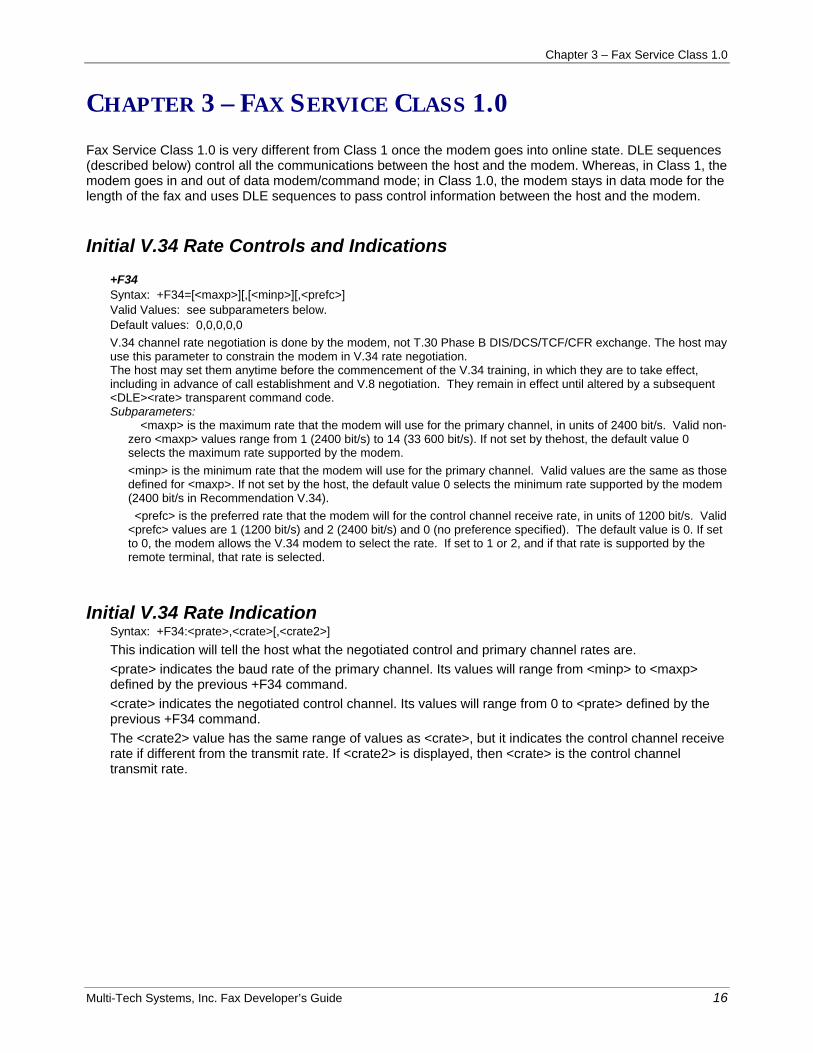
CHAPTER 3 – FAX SERVICE CLASS 1.0
Fax Service Class 1.0 is very different from Class 1 once the modem goes into online state. DLE sequences (described below) control all the communications between the host and the modem. Whereas, in Class 1, the modem goes in and out of data modem/command mode; in Class 1.0, the modem stays in data mode for the length of the fax and uses DLE sequences to pass control information between the host and the modem.
Initial V.34 Rate Controls and Indications +F34 Syntax: +F34=[<maxp>][,[<minp>][,<prefc>] Valid Values: see subparameters below. Default values: 0,0,0,0,0 V.34 channel rate negotiation is done by the modem, not T.30 Phase B DIS/DCS/TCF/CFR exchange. The host may use this parameter to constrain the modem in V.34 rate negotiation. The host may set them anytime before the commencement of the V.34 training, in which they are to take effect, including in advance of call establishment and V.8 negotiation. They remain in effect until altered by a subsequent <DLE><rate> transparent command code. Subparameters:
<maxp> is the maximum rate that the modem will use for the primary channel, in units of 2400 bit/s. Valid non-zero <maxp> values range from 1 (2400 bit/s) to 14 (33 600 bit/s). If not set by thehost, the default value 0 selects the maximum rate supported by the modem. <minp> is the minimum rate that the modem will use for the primary channel. Valid values are the same as those defined for <maxp>. If not set by the host, the default value 0 selects the minimum rate supported by the modem (2400 bit/s in Recommendation V.34). <prefc> is the preferred rate that the modem will for the control channel receive rate, in units of 1200 bit/s. Valid <prefc> values are 1 (1200 bit/s) and 2 (2400 bit/s) and 0 (no preference specified). The default value is 0. If set to 0, the modem allows the V.34 modem to select the rate. If set to 1 or 2, and if that rate is supported by the remote terminal, that rate is selected.
Initial V.34 Rate Indication Syntax: +F34:<prate>,<crate>[,<crate2>] This indication will tell the host what the negotiated control and primary channel rates are. <prate> indicates the baud rate of the primary channel. Its values will range from <minp> to <maxp> defined by the previous +F34 command. <crate> indicates the negotiated control channel. Its values will range from 0 to <prate> defined by the previous +F34 command. The <crate2> value has the same range of values as <crate>, but it indicates the control channel receive rate if different from the transmit rate. If <crate2> is displayed, then <crate> is the control channel transmit rate.

Chapter 3 – Fax Service Class 1.0
Multi-Tech Systems, Inc. Fax Developer’s Guide 17
Call Initiation The call initiation sequence is the same for the originate and answer modes. After the initial V.34 handshake is complete, both sides (originate and answer) get a +F34 response indicating the connection speeds, a CONNECT response, and then a DLE sequence that indicates that the channel selected is the control channel and DLE shielded information about connect speeds (again). After this, the modem is in the online state.
Call Online In the online state, the originate modem initiates all switches from the control channel to the primary channel and back. The host sends a DLE followed by a character that indicates the speed and channel type to switch to. After the switch is accomplished, the modem sends a DLE-ctrl or DLE-pri sequence and DLE sequences indicating the transmission rates. Once a channel is selected, HDLC framed data can be sent by either side at any time (in order to send or receive a fax, however data should be sent in a predefined order per T.30).
Call Termination Unlike non-V.34 faxing, there is a constant carrier that indicates that a connection is in progress. Therefore there is an indication (i.e., DLE-EOT) that signals when the remote modem has disconnected the line. The same sequence is used to terminate the fax call.
Host Initiated Termination If the host terminates ATO execution by <DLE><EOT>, the modem will:
a) if sending an HDLC frame, complete sending the frame, including FCS and final flag; b) send an HDLC abort; c) send any V.34 specific carrier termination signals; d) wait for remote carrier to turn off; e) stop carrier transmission; f) issue <DLE><EOT> and an OK final result code to the host; g) stay connected to the GSTN; h) switch to command mode.
Modem Initiated Termination If the modem detects remote disconnection or receives at least 40 consecutive ones from the remote modem, the modem will:
a) stop carrier transmission; b) stay connected to the GSTN; c) send <DLE><EOT> to the host; d) issue an OK final result code to the host; e) switch to command mode.

Chapter 3 – Fax Service Class 1.0
Multi-Tech Systems, Inc. Fax Developer’s Guide 18
DLE Sequences In V.34 fax, the DLE sequences defined in Class 1 are expanded to include all the functions necessary to send/receive a V.34 fax.
Transparent Data Commands
Service HEX Values
Description
<DLE><DLE> <DLE><SUB>
10-10 10-1A
Character Transparency: substitute one 10h pattern substitute two 10h patterns
<DLE><DC1> <DLE><DC3>
10-51 10-53
Shielded Control Words: substitute one 11h pattern to enable flow control substitute one 13h pattern to disable flow control
<DLE><ETX> <DLE><ferr>
10-03 10-07
HDLC frame Delimiters: End of HDLC frame w/o detected FCS error End of HDLC frame with FCS error
<DLE><EOT> <DLE><pri> <DLE><ctrl> <DLE><pph> <DLE><mark> <DLE><rtnc>
10-04 10-6B 10-6D 10-6C 10-68 10-69
V.34 mode selection/indication: End transmission Select primary channel Select control channel Request primary rate renegotiation Initiate termination of send Request control channel retrain
<DLE><c12> <DLE><c24>
10-6E 10-6F
V.34 control channel rate request/indication: 1200 bit/s 2400 bit/s
<DLE><p24> <DLE><p48> <DLE><p72> <DLE><p96> <DLE><p120> <DLE><p144> <DLE><p168> <DLE><p192> <DLE><p216> <DLE><p240> <DLE><p264> <DLE><p288> <DLE><p312> <DLE><p336>
10-70 10-71 10-72 10-73 10-74 10-75 10-76 10-77 10-78 10-79 10-7A 10-7B 10-7C 10-7D
V.34 primary channel rate request/indication: 2 400 bit/s 4 800 bit/s 7 200 bit/s 9 600 bit/s 12 000 bit/s 14 400 bit/s 16 800 bit/s 19 200 bit/s 21 600 bit/s 24 000 bit/s 26 400 bit/s 28 800 bit/s 31 200 bit/s 33 600 bit/s

Chapter 3 – Fax Service Class 1.0
Multi-Tech Systems, Inc. Fax Developer’s Guide 19
Host-Modem Data For V.34 transfer between HOST and MODEM, the following procedures apply:
Host to Modem Messages After the CONNECT result code, the modem will accept three types of data from the host.
a) Transparent data commands, as defined in the Transparent Data Commands table on the previous page.
b) HDLC frame octets, terminated by <DLE><ETX>. c) <DLE><DC1> and <DLE><DC3> commands for flow control of data from the modem.
Modem to Host Messages After the CONNECT result code, the modem will send three types of data to the host.
a) Transparent data indications, as defined in the Transparent Data Commands table on the previous page.
b) HDLC frame octets, terminated by <DLE><ETX> or <DLE><ferr>. c) <DLE><DC1> and <DLE><DC3> commands for flow control of data from the host.
HDLC Frame Data The modem will transmit FLAGs upon host data underrun. HDLC frame octet data may not contain control character <DLE>. Therefore, the Transparent Data commands, defined in the Transparent Data Commands table on the previous page, must be used to represent the characters. Each HDLC frame sent from the host to the modem must be terminated by the <DLE><ETX> transparent data command. Each HDLC frame sent from the modem to the host will be terminated by the <DLE><ETX> transparent data command if the received FCS sequence is valid, or by the <DLE><ferr> transparent data command if the received FCS sequence is invalid. This received HDLC frame will include the FCS sequence, or a substitute sequence of the same length.

Chapter 3 – Fax Service Class 1.0
Multi-Tech Systems, Inc. Fax Developer’s Guide 20
Class 1.0 Sample Sessions In the following examples, actions between the host and modem on both the originating and answering side are illustrated. For conciseness, T.30 HDLC frames in these examples are represented by their T.30 three-character frame abbreviation in [square brackets]. [DIS] represents the Control, Address, and FIF, terminated by <DLE><ETX>, or by <DLE><ferr> if an FCS error was detected on reception. The symbolic versions of transparent data commands are used for clarity. Some instances of rate changes and renegotiations are included. However, this does not imply that these are common occurrences in V.34 operation.
Chapter 3 – Fax Service Class 1.0
Multi-Tech Systems, Inc. Fax Developer’s Guide 21
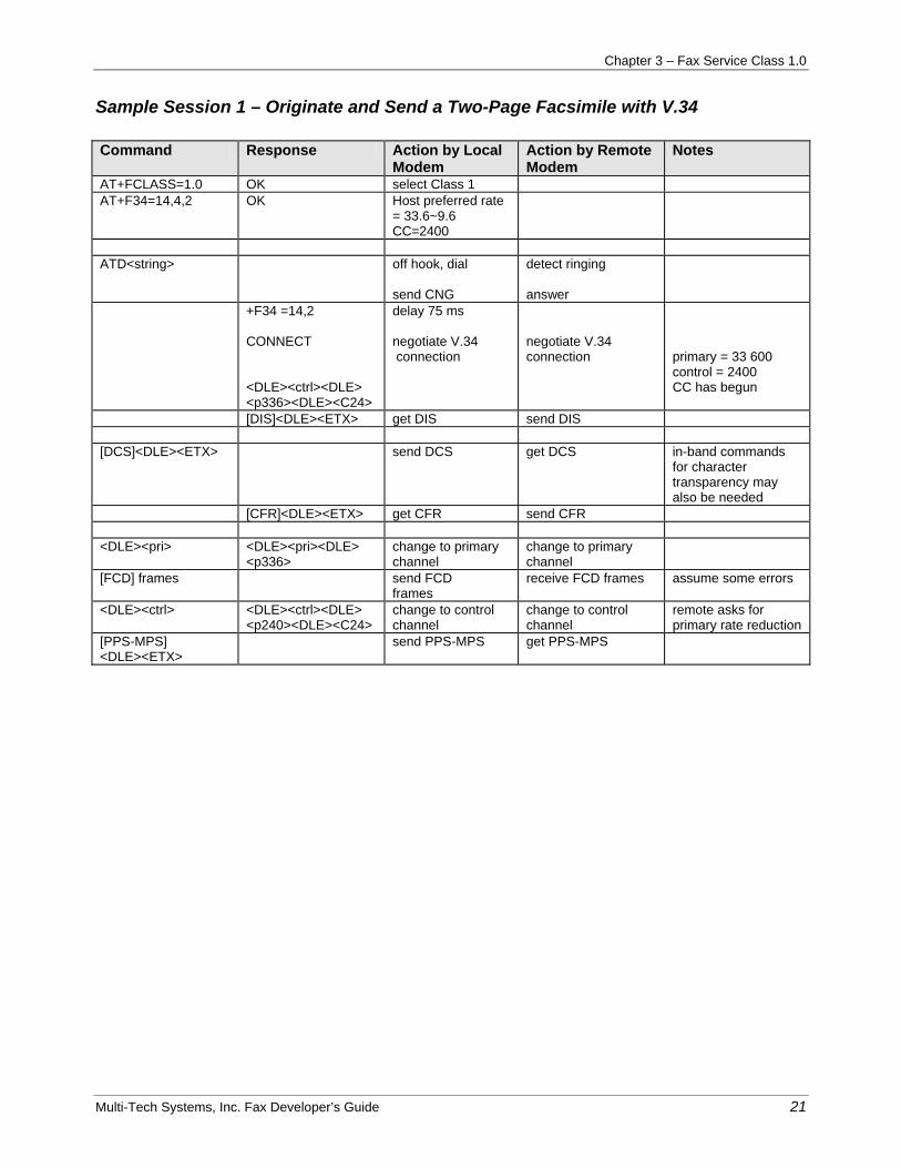
Sample Session 1 – Originate and Send a Two-Page Facsimile with V.34
Command Response Action by Local
Modem Action by Remote Modem
Notes
AT+FCLASS=1.0 OK select Class 1 AT+F34=14,4,2 OK Host preferred rate
= 33.6~9.6 CC=2400
ATD<string> off hook, dial
send CNG
detect ringing answer
+F34 =14,2 CONNECT <DLE><ctrl><DLE> <p336><DLE><C24>
delay 75 ms negotiate V.34 connection
negotiate V.34 connection
primary = 33 600 control = 2400 CC has begun
[DIS]<DLE><ETX> get DIS send DIS [DCS]<DLE><ETX> send DCS get DCS in-band commands
for character transparency may also be needed
[CFR]<DLE><ETX> get CFR send CFR <DLE><pri> <DLE><pri><DLE>
<p336> change to primary channel
change to primary channel
[FCD] frames send FCD frames
receive FCD frames assume some errors
<DLE><ctrl> <DLE><ctrl><DLE> <p240><DLE><C24>
change to control channel
change to control channel
remote asks for primary rate reduction
[PPS-MPS] <DLE><ETX>
send PPS-MPS get PPS-MPS

Chapter 3 – Fax Service Class 1.0
Multi-Tech Systems, Inc. Fax Developer’s Guide 22
Command Response Action by Local
Modem Action by Remote Modem
Notes
[PPR]<DLE><ETX> get PPR send PPR report errors <DLE><pri> <DLE><pri><DLE>
<p240> change to primary at24 000 bit/s
change to primary at 24 000 bit/s
retry on some [FCD] frames
send FCD frames receive FCD frames no more errors
<DLE><ctrl> <DLE><ctrl><DLE>
<p240><DLE><c12> change to control channel
change to control channel
remote wants to reduced CC rate
[PPS-MPS] <DLE><ETX>
send PPS-MPS get PPS-MPS
[MCF]<DLE><ETX> get MCF send MCF <DLE><pri> <DLE><pri><DLE>
<p240> change to primary w/o rate change
change to primary w/o rate change
leave primary rate, modem does not step up
send new [FCD] for second page
send second page FCD
received second page
<DLE><ctrl> <DLE><p240><DLE><
c12><DLE><ctrl> change to control channel
change to control channel
[PPS-EOP] <DLE><ETX>
send PPS-EOP get PPS-EOP
[MCF]<DLE><ETX> get MCF send MCF [DCN]<DLE><ETX> send DCN get DCN <DLE><EOT>
OK terminate V.34 channel
detect V.34 channel termination
ATH OK hang up
Chapter 3 – Fax Service Class 1.0
Multi-Tech Systems, Inc. Fax Developer’s Guide 23
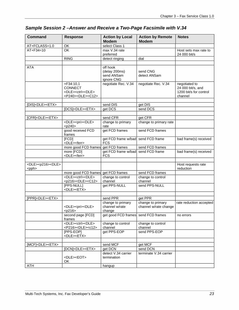
Sample Session 2 –Answer and Receive a Two-Page Facsimile with V.34
Command Response Action by Local Modem
Action by Remote Modem
Notes
AT+FCLASS=1.0 OK select Class 1 AT+F34=10 OK max V.34 rate
preferred Host sets max rate to
24 000 bit/s RING detect ringing dial ATA
off hook (delay 200ms) send ANSam ignore CNG
send CNG detect ANSam
+F34:10,1 CONNECT <DLE><ctrl><DLE> <P240><DLE><C12>
negotiate Rec. V.34 negotiate Rec. V.34 negotiated to 24 000 bit/s, and 1200 bit/s for control channel
[DIS]<DLE><ETX> send DIS get DIS [DCS]<DLE><ETX> get DCS send DCS [CFR]<DLE><ETX> send CFR get CFR <DLE><pri><DLE>
<p240> change to primary rate
change to primary rate
good received FCD frames
get FCD frames send FCD frames
[FCD] <DLE><ferr>
get FCD frame w/bad FCS
send FCD frame bad frame(s) received
more good FCD frames get FCD frames send FCD frames more [FCD]
<DLE><ferr> get FCD frame w/bad FCS
send FCD frame bad frame(s) received
<DLE><p216><DLE><pph>
Host requests rate reduction
more good FCD frames get FCD frames send FCD frames <DLE><ctrl><DLE>
<p216><DLE><C12> change to control channel
change to control channel
[PPS-NULL] <DLE><ETX>
get PPS-NULL send PPS-NULL
[PPR]<DLE><ETX> send PPR get PPR
<DLE><pri><DLE> <p216>
change to primary channel w/rate change
change to primary channel w/rate change
rate reduction accepted
second page [FCD] frames
get good FCD frames send FCD frames no errors
<DLE><ctrl><DLE> <P216><DLE><c12>
change to control channel
change to control channel
[PPS-EOP] <DLE><ETX>
get PPS-EOP send PPS-EOP
[MCF]<DLE><ETX> send MCF get MCF [DCN]<DLE><ETX> get DCN send DCN
<DLE><EOT> OK
detect V.34 carrier termination
terminate V.34 carrier
ATH hangup

Chapter 3 – Fax Service Class 1.0
Multi-Tech Systems, Inc. Fax Developer’s Guide 24
INDEX
AT commands, 6 Class 1
Answered Calls, 6 Call Online, 6 Call Termination, 6 DLE Sequences, 6 Fax Command Summary, 7 Originated Calls, 6 services, 7
Class 1 AT Commands, 6 Class 1 fax commands
Sample sessions, 13 Class 1 Fax commands
+FCLASS?, 9 +FCLASS=?, 9 +FCLASS=<value>, 9 +FRH=?, 12 +FRH=<MOD>, 11 +FRM<MOD>, 11 +FRM=?, 11 +FRS=?, 10 +FRS=<time>, 10 +FTH=?, 11 +FTH=<MOD>, 11
+FTM?, 10 +FTM=<MOD>, 10 +FTS=?, 10 +FTS=<time>, 9 Result codes, 12
Class 1.0 Call Initiation, 6, 17 Call Online, 17 Call Termination, 17 Host Initiated Termination, 17 Initial V.34 Rate Controls and Indications, 16 Initial V.34 Rate Indication, 16 Modem Initiated Termination, 17
Class 1.0 Sample Sessions, 20 contrast to Service Classes 2/2.0/21, 4 Fax MOD (Modulation) Parameter Values, 8 HDLC frame data, 19 Host to Modem Messages, 19 Mode, to Host Messages, 19 Service Class 1 uses, 4 Super G3, 4 Table of Capabilities, 4 Transparent Data Commands Table, 18 V.34 Mode, 5


![Service Manual Fax[1]](https://img.pdfslide.us/doc/110x75/577ccd211a28ab9e788b9525/service-manual-fax1.jpg)