Embed Size (px)
Citation preview

FAULT CHARACTERISATIO AD CLASSIFICATIO USIG
WAVELET AD FAST FOURIER TRASFORMS
E. E NGU, K. RAMAR
Multimedia University
FOE, MMU, Persiaran Multimedia, 63100
MALAYSIA
[email protected], [email protected]
R. MONTANO, V. COORAY
High Voltage Valley
Fredsgatan 27, P.O.Box 832, SE-77128 Ludvika
SWEDEN
Abstract: - In order to improve the power quality maintenance and reliability of power supply, different types of faults on
the transmission line namely: open-circuit (OC), short-circuit (SC), high impedance faults (HIF) and the fault caused by
direct lightning strike (LS) have been investigated in this paper. The disturbances have been modelled and simulated using
a well-known transient simulation tool - Alternative Transient Program/ Electromagnetic Transient Program (ATP/EMTP)
and the resulting data are then imported into MATLAB for the investigation on the traveling wave (TW) reflection pattern
and harmonic behaviour . Study on the characteristics of the faults in terms of their corresponding frequency spectrum, the
polarities of the incident-wave and reflected-wave has been performed and the possibility to differentiate the type of fault
is explored. For this purpose, the fault on the wave has been created at the moment when the voltage signal reaches its
peak and also when it is close to zero. Both, Wavelet Transform (WT) and Fast Fourier Transform (FFT) methods have
been used to analyze the transient signals generated by the fault. Model of the network used in this study is taken from
[1]-[2].
Key-words: - WT, FFT, ATP/EMTP, current reflection pattern, and spectrum analysis
1 ITRODUCTIO With the continuous and rapid extension of power
networks, development of automatic and reliable
technique for fault detection and location has recently
received considerable attention. It is well-known that
high frequency transient signals will be generated
whenever disturbances occur, where the power network
will lose its steady state condition, resulting in a large
number of cases with load drops. Thus, a robust and
stable fault location technique is required not only for
fast fault clearance to restore electricity supply, but also
the safety of power networks and human life.
During the past decade different kinds of fault
location algorithms either based on the single- or double-
end synchronized and unsynchronized measurement
methods, associated with different kinds of analysis
techniques such as WT, neural network, travelling wave
(TW), etc. have been developed. However, studies
associated with the characterization of the types of
disturbances/fault in relation to the various
methodologies/ techniques used for fault detection has
not been extensively reported in the literature.
Power quality monitoring under different types of
faults is very important in electrical power generation,
transmission and distribution. Therefore, the detection
and classification of type of disturbance must not be
neglected.
In this paper, a brief introduction to WT and FFT is
given in Section 2. Section 3 describes a method to
obtain high frequency transient signals by simulating a
Power System using ATP/EMTP for various types of
faults. Study on the characteristic of SC, OC, HIF and
LS types of faults based on their frequency content and
the polarity of incident and reflected waves from the
fault point as well as from the neighboring and/or remote
end busbars is given in Section 4. For this study the
MATLAB Wavelet Toolbox has been used. Section 5
gives the discussion and conclusion.
2 REVIEW OF TRAVELLIG WAVE
(TW) THEORY AD TRASFORM
TECHIQUES
WSEAS TRANSACTIONS on SIGNAL PROCESSING E. E Ngu, K. Ramar and R. Montano, V. Cooray
ISSN: 1790-5052 398 Issue 7, Volume 4, July 2008
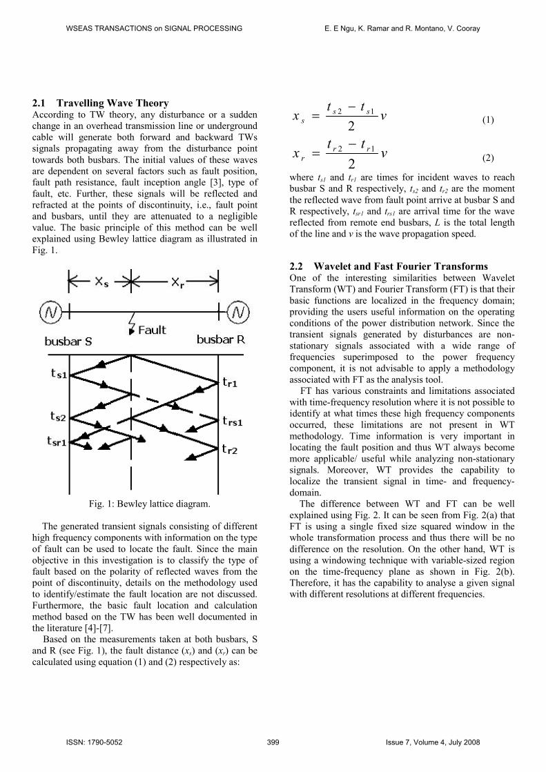
2.1 Travelling Wave Theory According to TW theory, any disturbance or a sudden
change in an overhead transmission line or underground
cable will generate both forward and backward TWs
signals propagating away from the disturbance point
towards both busbars. The initial values of these waves
are dependent on several factors such as fault position,
fault path resistance, fault inception angle [3], type of
fault, etc. Further, these signals will be reflected and
refracted at the points of discontinuity, i.e., fault point
and busbars, until they are attenuated to a negligible
value. The basic principle of this method can be well
explained using Bewley lattice diagram as illustrated in
Fig. 1.
Fig. 1: Bewley lattice diagram.
The generated transient signals consisting of different
high frequency components with information on the type
of fault can be used to locate the fault. Since the main
objective in this investigation is to classify the type of
fault based on the polarity of reflected waves from the
point of discontinuity, details on the methodology used
to identify/estimate the fault location are not discussed.
Furthermore, the basic fault location and calculation
method based on the TW has been well documented in
the literature [4]-[7].
Based on the measurements taken at both busbars, S
and R (see Fig. 1), the fault distance (xs) and (xr) can be
calculated using equation (1) and (2) respectively as:
vtt
x sss
2
12 −= (1)
vtt
x rrr
2
12 −= (2)
where ts1 and tr1 are times for incident waves to reach
busbar S and R respectively, ts2 and tr2 are the moment
the reflected wave from fault point arrive at busbar S and
R respectively, tsr1 and trs1 are arrival time for the wave
reflected from remote end busbars, L is the total length
of the line and v is the wave propagation speed.
2.2 Wavelet and Fast Fourier Transforms One of the interesting similarities between Wavelet
Transform (WT) and Fourier Transform (FT) is that their
basic functions are localized in the frequency domain;
providing the users useful information on the operating
conditions of the power distribution network. Since the
transient signals generated by disturbances are non-
stationary signals associated with a wide range of
frequencies superimposed to the power frequency
component, it is not advisable to apply a methodology
associated with FT as the analysis tool.
FT has various constraints and limitations associated
with time-frequency resolution where it is not possible to
identify at what times these high frequency components
occurred, these limitations are not present in WT
methodology. Time information is very important in
locating the fault position and thus WT always become
more applicable/ useful while analyzing non-stationary
signals. Moreover, WT provides the capability to
localize the transient signal in time- and frequency-
domain.
The difference between WT and FT can be well
explained using Fig. 2. It can be seen from Fig. 2(a) that
FT is using a single fixed size squared window in the
whole transformation process and thus there will be no
difference on the resolution. On the other hand, WT is
using a windowing technique with variable-sized region
on the time-frequency plane as shown in Fig. 2(b).
Therefore, it has the capability to analyse a given signal
with different resolutions at different frequencies.
WSEAS TRANSACTIONS on SIGNAL PROCESSING E. E Ngu, K. Ramar and R. Montano, V. Cooray
ISSN: 1790-5052 399 Issue 7, Volume 4, July 2008
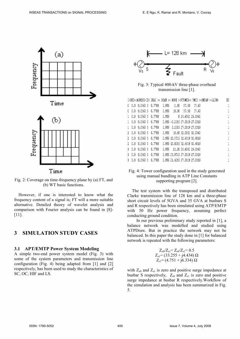
Fig. 2: Coverage on time-frequency plane by (a) FT, and
(b) WT basic functions.
However, if one is interested to know what the
frequency content of a signal is; FT will a more suitable
alternative. Detailed theory of wavelet analysis and
comparison with Fourier analysis can be found in [8]-
[11].
3 SIMULATIO STUDY CASES
3.1 APT/EMTP Power System Modeling A simple two-end power system model (Fig. 3) with
some of the system parameters and transmission line
configuration (Fig. 4) being adapted from [1] and [2]
respectively, has been used to study the characteristics of
SC, OC, HIF and LS.
Fig. 3: Typical 400-kV three-phase overhead
transmission line [1].
Fig. 4: Tower configuration used in the study generated
using manual bundling in ATP Line Constants
supporting program [2].
The test system with the transposed and distributed
Clarke transmission line of 128 km and a three-phase
short circuit levels of 5GVA and 35 GVA at busbars S
and R respectively has been simulated using ATP/EMTP
with 50 Hz power frequency, assuming perfect
conducting ground condition.
In our previous preliminary study reported in [1], a
balance network was modelled and studied using
ATPDraw. But in practice the network may not be
balanced. In this paper the study done in [1] for balanced
network is repeated with the following parameters:
Zs0/Zs1= Zr0/Zr1= 0.5
Zs1= (33.255 + j4.434) Ω
Zr1= (4.751 + j6.334) Ω
with Zs0 and Zs1 is zero and positive surge impedance at
busbar S respectively, Zr0 and Zr1 is zero and positive
surge impedance at busbar R respectively.Workflow of
the simulation and analysis has been summarized in Fig.
5.
WSEAS TRANSACTIONS on SIGNAL PROCESSING E. E Ngu, K. Ramar and R. Montano, V. Cooray
ISSN: 1790-5052 400 Issue 7, Volume 4, July 2008
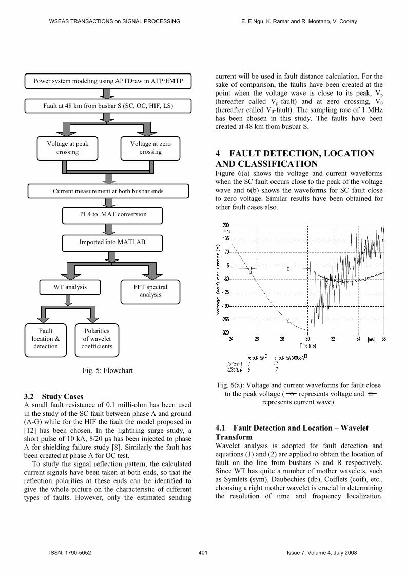
Fig. 5: Flowchart
3.2 Study Cases A small fault resistance of 0.1 milli-ohm has been used
in the study of the SC fault between phase A and ground
(A-G) while for the HIF the fault the model proposed in
[12] has been chosen. In the lightning surge study, a
short pulse of 10 kA, 8/20 µs has been injected to phase
A for shielding failure study [8]. Similarly the fault has
been created at phase A for OC test.
To study the signal reflection pattern, the calculated
current signals have been taken at both ends, so that the
reflection polarities at these ends can be identified to
give the whole picture on the characteristic of different
types of faults. However, only the estimated sending
current will be used in fault distance calculation. For the
sake of comparison, the faults have been created at the
point when the voltage wave is close to its peak, Vp
(hereafter called Vp-fault) and at zero crossing, V0
(hereafter called V0-fault). The sampling rate of 1 MHz
has been chosen in this study. The faults have been
created at 48 km from busbar S.
4 FAULT DETECTIO, LOCATIO
AD CLASSIFICATIO Figure 6(a) shows the voltage and current waveforms
when the SC fault occurs close to the peak of the voltage
wave and 6(b) shows the waveforms for SC fault close
to zero voltage. Similar results have been obtained for
other fault cases also.
Fig. 6(a): Voltage and current waveforms for fault close
to the peak voltage ( O represents voltage and 口
represents current wave).
4.1 Fault Detection and Location – Wavelet
Transform Wavelet analysis is adopted for fault detection and
equations (1) and (2) are applied to obtain the location of
fault on the line from busbars S and R respectively.
Since WT has quite a number of mother wavelets, such
as Symlets (sym), Daubechies (db), Coiflets (coif), etc.,
choosing a right mother wavelet is crucial in determining
the resolution of time and frequency localization.
Power system modeling using APTDraw in ATP/EMTP
Voltage at peak
crossing
Voltage at zero
crossing
Fault at 48 km from busbar S (SC, OC, HIF, LS)
Current measurement at both busbar ends
.PL4 to .MAT conversion
Imported into MATLAB
WT analysis FFT spectral
analysis
Fault
location &
detection
Polarities
of wavelet
coefficients
WSEAS TRANSACTIONS on SIGNAL PROCESSING E. E Ngu, K. Ramar and R. Montano, V. Cooray
ISSN: 1790-5052 401 Issue 7, Volume 4, July 2008

Consequently, a comparison among the sym, db and coif
wavelet families has been done and the results show
nominal differences among them.
As stated in [8], db wavelet families have been
chosen in most studies as they are well suited to power
quality analysis. Thus, db3 with level 1 (d1) coefficient
has been selected to detect the singularity in the transient
signals generated by the disturbances. It is to bear in
mind that, level 1 carries the most information compared
to levels 2, 3, etc. Higher the level, more information is
lost as the frequency component will be halved from
level to level. However, level 3 or 4 shall be chosen if
the noise content is considerable high in level 1.
Fig. 6(b): Voltage and current waveform for fault close
to zero voltage ( O represents voltage and 口
represents current wave).
Figures 7 to 11 show the outputs of WT and FFT
applied to the disturbed waveforms for different faults.
Each figure consists of three parts. Parts (i) and (ii) show
the detail of level 1 coefficients of WT applied to current
signals measured at ends S and R respectively and are
meant for fault detection and location. While part (iii) is
the discrete plot of frequency spectrum obtained using
FFT on the measured current signals that will be used in
fault characterisation. For a complete understanding/
analysis, the WT coefficients shown in parts (i)-(ii) of
Figs 7 to 10, have been scaled up to give a good view on
the changes of the resulting coefficients.
Table 1 shows the fault position calculated using
equation (1) based on the information extracted using
db3, where the arrival time of the TW at the busbar is
illustrated by the sudden change of the coefficients. The
fault has been created at 25 ms and 30 ms for the fault
close to zero voltage value, and the fault close to peak
voltage value, respectively. It can be seen from Table 1
that the error in the calculated fault distance for all types
of faults is within 400 m for both study cases.
Table 1
Calculated fault distance from busbar S and the
percentage of the error for V0- and Vp-faults
Type of
fault
Calculated fault distance
from end S, xs (km)
Error
(%)
V0-fault SC
∆t = 1 µs 47.67 0.68
∆t = 100 ns 47.85 0.31
OC 47.69 0.64
HIF 47.97 0.06
LS 47.68 0.68
Vp-fault SC
∆t = 1 µs 47.66 0.70
∆t = 100 ns 47.85 0.31
OC 47.68 0.68
HIF 47.68 0.68
LS 47.65 0.74
It is worth mentioning that in SC case, simulation has
been repeated with sampling time, ∆t =100 ns for V0 and
Vp faults and the results are shown in Fig. 7(c). This
repetition has been done as there were some inaccuracy
in the polarity of the WT coefficients when the
simulation is done with ∆t =1µs. But there was no
problem in fault location as it is decided by the
appearance of the disturbance and the polarity of WT
coefficients. However it is observed that the accuracy of
fault location is improved with increase in sampling rate.
For fault detection and location in LS case, result
obtained from the WT analysis shows that the injection
of the pulse introduces only a very fast transient on the
transmission line and no fault persisting on the line.
Even so, the point of disturbance can still be detected
and located using the information in the current signals
using WT. From Table 1 it can be concluded that the
fault location using WT is quite satisfactory for all types
of faults.
4.2 Traveling Wave Reflection Pattern and
Fault Classification – Fast Fourier and Wavelet
Transforms
WSEAS TRANSACTIONS on SIGNAL PROCESSING E. E Ngu, K. Ramar and R. Montano, V. Cooray
ISSN: 1790-5052 402 Issue 7, Volume 4, July 2008
In this section the type of fault and its characteristic are
investigated and classified using lattice diagram and
spectral analysis.
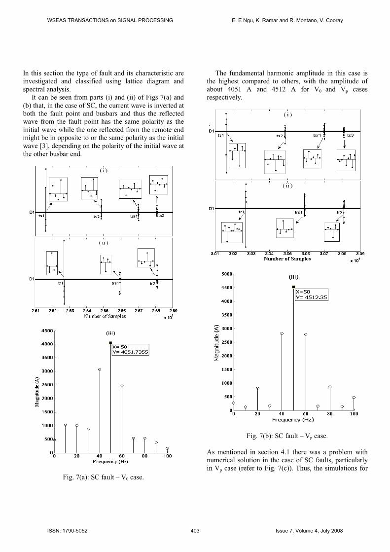
It can be seen from parts (i) and (ii) of Figs 7(a) and
(b) that, in the case of SC, the current wave is inverted at
both the fault point and busbars and thus the reflected
wave from the fault point has the same polarity as the
initial wave while the one reflected from the remote end
might be in opposite to or the same polarity as the initial
wave [3], depending on the polarity of the initial wave at
the other busbar end.
Fig. 7(a): SC fault – V0 case.
The fundamental harmonic amplitude in this case is
the highest compared to others, with the amplitude of
about 4051 A and 4512 A for V0 and Vp cases
respectively.
Fig. 7(b): SC fault – Vp case.
As mentioned in section 4.1 there was a problem with
numerical solution in the case of SC faults, particularly
in Vp case (refer to Fig. 7(c)). Thus, the simulations for
WSEAS TRANSACTIONS on SIGNAL PROCESSING E. E Ngu, K. Ramar and R. Montano, V. Cooray
ISSN: 1790-5052 403 Issue 7, Volume 4, July 2008
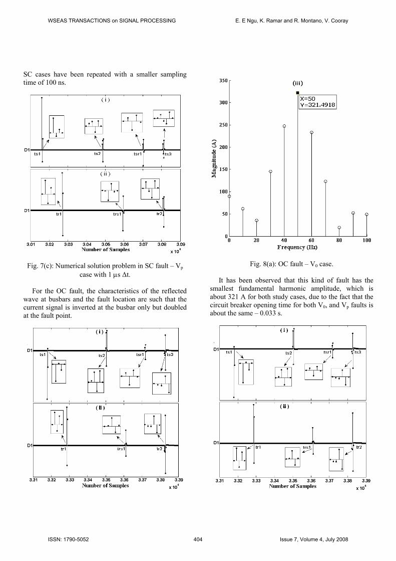
SC cases have been repeated with a smaller sampling
time of 100 ns.
Fig. 7(c): Numerical solution problem in SC fault – Vp
case with 1 µs ∆t.
For the OC fault, the characteristics of the reflected
wave at busbars and the fault location are such that the
current signal is inverted at the busbar only but doubled
at the fault point.
Fig. 8(a): OC fault – V0 case.
It has been observed that this kind of fault has the
smallest fundamental harmonic amplitude, which is
about 321 A for both study cases, due to the fact that the
circuit breaker opening time for both V0, and Vp faults is
about the same – 0.033 s.
WSEAS TRANSACTIONS on SIGNAL PROCESSING E. E Ngu, K. Ramar and R. Montano, V. Cooray
ISSN: 1790-5052 404 Issue 7, Volume 4, July 2008

Fig. 8(b): OC fault – Vp case.
Nevertheless, as illustrated by Fig. 8(c) the amplitude
of the first harmonic could reach about 410 A if the fault
point-on-wave occurs at negative going transition either
at the time of 0.035 s or 0.04 s. It is because for OC case,
circuit breaker opening and closing time is somehow
governed by magnitude of the current on the wave. It is
also to bear in mind that the current resulted at the
sending and receiving ends are due to the capacitive- and
inductive-effect associated with the long transmission
line used for the present study.
Fig. 8(c): OC fault – V0 (0.035 s) and Vp (0.04 s) cases
Fig. 9(a): HIF – V0 case.
In the previous preliminary investigation on the HIF,
reported in [1] it was found that characteristic of the TW
reaching at busbars under V0 condition is the same as the
SC case. But, in the case of Vp, it was found that the
signal was inverted at busbar R and fault point seen from
R, and it was doubled at busbar S and the fault point
seen from S [1]. However, in the present study with
WSEAS TRANSACTIONS on SIGNAL PROCESSING E. E Ngu, K. Ramar and R. Montano, V. Cooray
ISSN: 1790-5052 405 Issue 7, Volume 4, July 2008
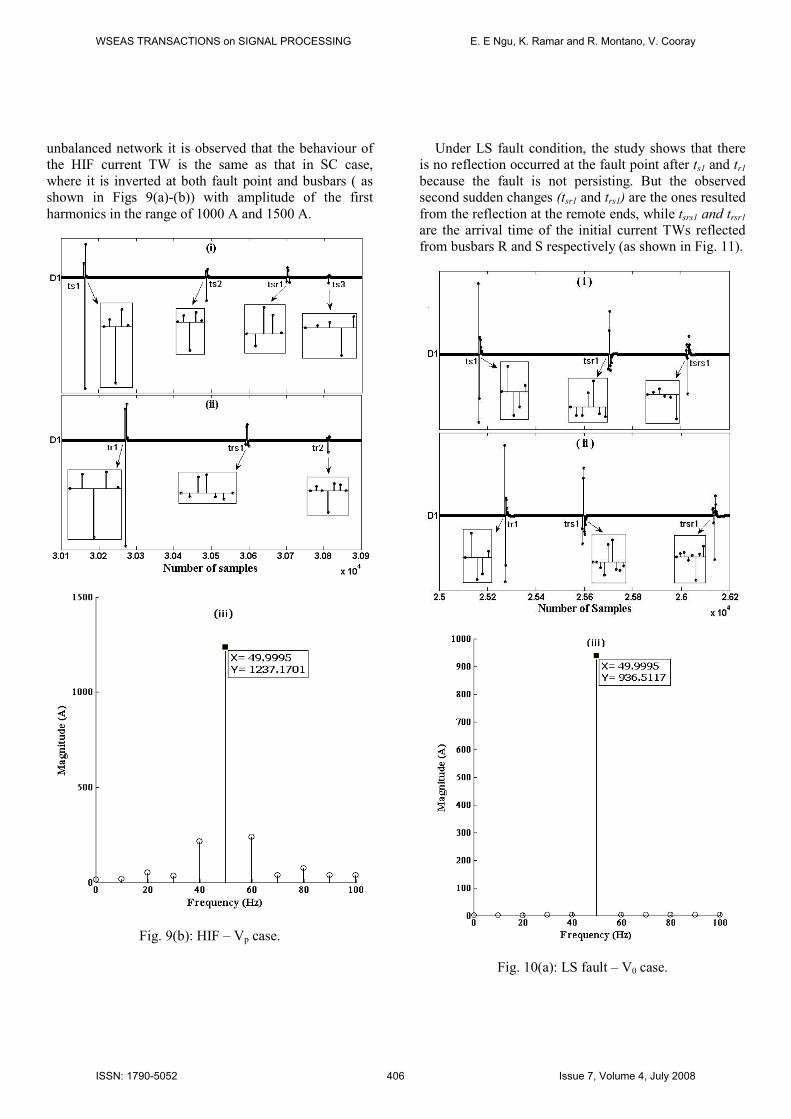
unbalanced network it is observed that the behaviour of
the HIF current TW is the same as that in SC case,
where it is inverted at both fault point and busbars ( as
shown in Figs 9(a)-(b)) with amplitude of the first
harmonics in the range of 1000 A and 1500 A.
Fig. 9(b): HIF – Vp case.
Under LS fault condition, the study shows that there
is no reflection occurred at the fault point after ts1 and tr1
because the fault is not persisting. But the observed
second sudden changes (tsr1 and trs1) are the ones resulted
from the reflection at the remote ends, while tsrs1 and trsr1
are the arrival time of the initial current TWs reflected
from busbars R and S respectively (as shown in Fig. 11).
Fig. 10(a): LS fault – V0 case.
WSEAS TRANSACTIONS on SIGNAL PROCESSING E. E Ngu, K. Ramar and R. Montano, V. Cooray
ISSN: 1790-5052 406 Issue 7, Volume 4, July 2008
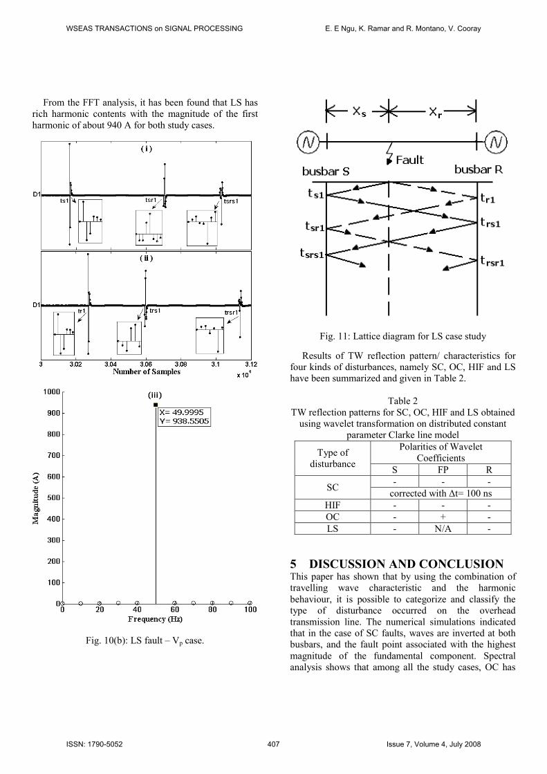
From the FFT analysis, it has been found that LS has
rich harmonic contents with the magnitude of the first
harmonic of about 940 A for both study cases.
Fig. 10(b): LS fault – Vp case.
Fig. 11: Lattice diagram for LS case study
Results of TW reflection pattern/ characteristics for
four kinds of disturbances, namely SC, OC, HIF and LS
have been summarized and given in Table 2.
Table 2
TW reflection patterns for SC, OC, HIF and LS obtained
using wavelet transformation on distributed constant
parameter Clarke line model
Type of
disturbance
Polarities of Wavelet
Coefficients
S FP R
SC - - -
corrected with ∆t= 100 ns
HIF - - -
OC - + -
LS - N/A -
5 DISCUSSIO AD COCLUSIO This paper has shown that by using the combination of
travelling wave characteristic and the harmonic
behaviour, it is possible to categorize and classify the
type of disturbance occurred on the overhead
transmission line. The numerical simulations indicated
that in the case of SC faults, waves are inverted at both
busbars, and the fault point associated with the highest
magnitude of the fundamental component. Spectral
analysis shows that among all the study cases, OC has
WSEAS TRANSACTIONS on SIGNAL PROCESSING E. E Ngu, K. Ramar and R. Montano, V. Cooray
ISSN: 1790-5052 407 Issue 7, Volume 4, July 2008

the smallest magnitude for the first harmonic component
while the first harmonic component for HIF lies in
between the values for SC and OC cases. For the LS
case, WT result shows that it is still possible to locate
where the disturbance has occurred even though the LS
is not persisting. For the purpose of comparison,
parameters such as the time of fault, the line constants,
the type of switch or circuit breaker used, etc. are to be
taken into consideration while doing the analysis. The
result reported is a preliminary investigation to identify
the type of faults based on the traveling wave observed
at the sending end using distributed constant parameter
Clarke line model under perfect conducting ground
condition. This study can be further extended to develop
intelligent techniques to classify the type of disturbance
in a power system. Study on the line-to-line fault and/ or
other types of disturbances associated with different
kinds of overhead transmission line models are under
progress and will be reported shortly.
ACKOWLEDGEMETS
Authors would like to thank the Swedish Institute for the
sponsorship of the Guest Scholarship Programme with
the sponsorship number of 00287/7007-210.
References:
[1] E. E. Ngu, K. Ramar, R. Montano, V. Cooray, A
Study on Different Fault Characteristics Using Wavelet
and Fast Fourier Transforms, Proceeding 7th
International WSEAS Conference on Application of
Electrical Engineering, 2008, pp. 124-130.
[2] A.R. Almeida, A.K. Barros, M.G. DeSousa, Faults
Location in High Voltage Transmission System Using
ICA. International IEEE Conference on Electrical
Engineering, 2007, pp. 1-6. [3] Z. Q. Bo, A. T. Johns & A. K. Aggarwal, A Novel
Fault Locator Based on the Detection of Fault Generated
High Frequency Transients, Proceeding 6th International
IEE Conference on Developments in Power Systems
Protection, 1997, pp. 197-200.
[4] D. J. Zhang, Q. H. Wu, Z. Q. Bo & B. Caunce,
Transient Position Protection of Lines Using Complex
Wavelets Analysis, IEEE Transaction on Power
Delivery, Vol.18, No.3, 2003, pp. 705-710.
[5] H. Hizam, P. A. Crossley, P. F. Gale & G. Bryson,
Fault Section Identification and Location on A
Distribution Feeder Using Travelling Waves, IEEE
Power Engineering Society Summer Meeting, 2002, pp.
1107-1112.
[6] D. Naidoo & N. M. Ijumba, Protection Method for
Long HVDC Transmission Lines, Proceeding 14th
International Symposium on High Voltage Engineering,
2005, pp. 1-6.
[7] C. Y. Evrenosoglu & A. Abur, Traveling Wave
Based Fault Location for Teed Circuits, IEEE
Transaction on Power Delivery, Vol.20, No.2, 2005, pp.
1115-1121.
[8] S. A. Probert & Y. H. Song, Detection and
Classification of High Frequency Transients Using
Wavelet Analysis, Proceeding IEEE Power Engineering
Society Summer Meeting, 2002, pp. 801-806.
[9] D. C. Robertson, O. I. Camps, J. S. Mayer & W. B.
Gish, Wavelet and Electromagnetic Power System
Transients, IEEE Transaction on Power Delivery,
Vol.11, No.2, 1996, pp. 1050-1056.
[10] S. G. Mallat, A Theory for Multiresolution Signal
Decomposition: The Wavelet Representation, IEEE
Transaction Pattern Anal. Machine Intelligent, Vol.11,
No.7, 1989, pp. 674-693.
[11] X. Wang, Q. Qian, & W. Chen, Analyzing Fault-
Induced Transients with Wavelets, Proceeding IEEE
Power Engineering Society Summer Meeting, 2002, pp.
1090-1093.
[12] T. M. Lai, L. A. Snider, E. Lo, & D. Sutanto, High-
Impedance Fault Detection Using Discrete Wavelet
Transform and Frequency Range and RMS Conversion,
IEEE Transaction on Power Delivery, Vol.20, No.1,
2005, pp. 397-407.
[13] Naser Zamanan, Jan K. Sykulski, Modelling Arcing
High Impedances Faults in Relation to the Physical
Processes in the Electric Arc. WSEAS Transaction on
Power Systems, Vol.8, No.1, 2006, pp. 1507-1512.
[14] Raimundo Nonato M. Machado, Ubiratan H.
Bezerra, Evaldo G. Pelaes, Roberto Celio L. De
Oliveira, Maria Emilia De Lima Tostes, Classification of
Signals with Voltage Disturbance by Means of Wavelet
Transform and Intelligent Computational Techniques,
WSEAS Transaction on Power Systems, Vol.8, No.1,
2006, pp. 1538-1542.
[15] J. Barros, R. I. Diego, Time-Frequency Analysis of
Harmonics in Power Systems using Wavelets. WSEAS
Transaction on Circuits and Systems, Vol.11, No.1,
2006, pp. 1924-1929.
WSEAS TRANSACTIONS on SIGNAL PROCESSING E. E Ngu, K. Ramar and R. Montano, V. Cooray
ISSN: 1790-5052 408 Issue 7, Volume 4, July 2008